Aerohive Networks AP122 Access Point User Manual AP122 Hardware User Guide
Aerohive Networks, Inc. Access Point AP122 Hardware User Guide
UserManual.wiki
>
Aerohive Networks
>
AP122 User Manual
User Manual
Navigation menu
Upload a User Manual
Namespaces
Wiki Guide
HTML
PDF
Info
Views
User Manual
Discussion / Help
Navigation
![EN 301 489-1 V1.9.2: Electromagnetic compatibility and Radio spectrum Matters (ERM); Electromagnetic Compatibility (EMC) standard for radio equipment and services; Part 1: Common technical requirementsEN 301 489-17 V2.2.1 Electromagnetic compatibility and Radio spectrum Matters (ERM); Electromagnetic Compatibility (EMC) standard for radio equipment; Part 17: Specific conditions for Broadband Data Transmission SystemsIn Italy the end-user should apply for a license at the national spectrum authorities in order to obtain authorization to use the device for setting up outdoor radio links and/or for supplying public access to telecommunications and/or network services.•Česky [Czech]: [Aerohive] tímto prohlašuje, že tento [AP122] je ve shodě se základnímipožadavky a dalšími příslušnými ustanoveními směrnice 1999/5/ES.•Dansk [Danish]: Undertegnede [Aerohive] erklærer herved, at følgende udstyr [AP122]overholder de væsentlige krav og øvrige relevante krav i direktiv 1999/5/EF.•Deutsch [German]: Hiermit erklärt [Aerohive], dass sich das Gerät [AP122] inÜbereinstimmung mit den grundlegenden Anforderungen und den übrigen einschlägigenBestimmungen der Richtlinie 1999/5/EG befindet.•Eesti [Estonian]: Käesolevaga kinnitab [Aerohive] seadme [AP122] vastavust direktiivi1999/5/EÜ põhinõuetele ja nimetatud direktiivist tulenevatele teistele asjakohastele sätetele.•English: Hereby, [Aerohive], declares that this [AP122] is in compliance with the essentialrequirements and other relevant provisions of Directive 1999/5/EC.•Español [Spanish]: Por medio de la presente [Aerohive] declara que el [AP130] cumple conlos requisitos esenciales y cualesquiera otras disposiciones aplicables o exigibles de laDirectiva 1999/5/CE.•Ελληνική [Greek]: ΜΕ ΤΗΝ ΠΑΡΟΥΣΑ [Aerohive] ΔΗΛΩΝΕΙ ΟΤΙ [AP122] ΣΥΜΜΟΡΦΩΝΕΤΑΙΠΡΟΣ ΤΙΣ ΟΥΣΙΩΔΕΙΣ ΑΠΑΙΤΗΣΕΙΣ ΚΑΙ ΤΙΣ ΛΟΙΠΕΣ ΣΧΕΤΙΚΕΣ ΔΙΑΤΑΞΕΙΣ ΤΗΣ ΟΔΗΓΙΑΣ 1999/5/ΕΚ.•Français [French]: Par la présente [Aerohive] déclare que l'appareil [AP130] est conformeaux exigences essentielles et aux autres dispositions pertinentes de la directive 1999/5/CE.•Italiano [Italian]: Con la presente [Aerohive] dichiara che questo [AP122] è conforme airequisiti essenziali ed alle altre disposizioni pertinenti stabilite dalla direttiva 1999/5/CE.•Latviski [Latvian]: Ar šo [Aerohive] deklarē, ka [AP122] atbilst Direktīvas 1999/5/EK būtiskajāmprasībām un citiem ar to saistītajiem noteikumiem.•Lietuvių [Lithuanian]: Šiuo [Aerohive] deklaruoja, kad šis [AP122] atitinka esminius reikalavimusir kitas 1999/5/EB Direktyvos nuostatas.•Nederlands [Dutch]: Hierbij verklaart [Aerohive] dat het toestel [AP122] in overeenstemmingis met de essentiële eisen en de andere relevante bepalingen van richtlijn 1999/5/EG.•Malti [Maltese]: Hawnhekk, [Aerohive], jiddikjara li dan [AP122] jikkonforma mal-ħtiġijietessenzjali u ma provvedimenti oħrajn relevanti li hemm fid-Dirrettiva 1999/5/EC.•Magyar [Hungarian]: Alulírott, [Aerohive] nyilatkozom, hogy a [AP122] megfelel a vonatkozóalapvetõ követelményeknek és az 1999/5/EC irányelv egyéb elõírásainak.•Polski [Polish]: Niniejszym [Aerohive] oświadcza, że [AP122] jest zgodny z zasadniczymiwymogami oraz pozostałymi stosownymi postanowieniami Dyrektywy 1999/5/EC.•Português [Portuguese]: [Aerohive] declara que este [AP122] está conforme com osrequisitos essenciais e outras disposições da Directiva 1999/5/CE.Page 3 of 14AP122 Hardware User Guide11/14/2016](https://usermanual.wiki/Aerohive-Networks/AP122/User-Guide-3220091-Page-3.png)
![•Slovensko [Slovenian]: [Aerohive] izjavlja, da je ta [AP122] v skladu z bistvenimi zahtevami inostalimi relevantnimi določili direktive 1999/5/ES.•Slovensky [Slovak]: [Aerohive] týmto vyhlasuje, že [AP122] spĺňa základné požiadavky avšetky príslušné ustanovenia Smernice 1999/5/ES.•Suomi [Finnish]: [Aerohive] vakuuttaa täten ettät [AP122] tyyppinen laite on direktiivin1999/5/EY oleellisten vaatimusten ja sitä koskevien direktiivin muiden ehtojen mukainen.Federal Communication Commission Interference StatementThis equipment has been tested and found to comply with the limits for a Class B digital device, pursuant to Part 15 of the FCC Rules. These limits are designed to provide reasonable protection against harmful interference in a residential installation. This equipment generates, uses and can radiate radio frequency energy and, if not installed and used in accordance with the instructions, may cause harmful interference to radio communications. However, there is no guarantee that interference will not occur in a particular installation. If this equipment does cause harmful interference to radio or television reception, which can be determined by turning the equipment off and on, the user is encouraged to try to correct the interference by one of the following measures:• Reorient or relocate the receiving antenna.• Increase the separation between the equipment and receiver.• Connect the equipment into an outlet on a circuit different from that to which the receiver isconnected.• Consult the dealer or an experienced radio/TV technician for help.FCC Caution: Any changes or modifications not expressly approved by the party responsible for compliance could void the user's authority to operate this equipment.This device complies with Part 15 of the FCC Rules. Operation is subject to the following two conditions: (1) This device may not cause harmful interference, and (2) this device must accept any interference received, including interference that may cause undesired operation.This device and its antenna(s) must not be co-located or operating in conjunction with any other antenna or transmitter except in accordance with FCC multi-transmitter product procedures. If this device operates in the 5.15~5.25 GHz frequency range, it is restricted to indoor use only.IMPORTANT NOTE:Radiation Exposure Statement:This equipment complies with FCC radiation exposure limits set forth for an uncontrolled environment. This equipment should be installed and operated with a minimum distance of 7.8" (20 cm) between the radiator people or animals.This transmitter must not be co-located or operating in conjunction with any other antenna or transmitter.Canada Regulatory ISED Statements:This device complies with ISED (Innovation, Science and Economic Development) Canada license-exempt RSS standard(s). Operation is subject to the following two conditions:1. This device may not cause interference, andPage 4 of 14AP122 Hardware User Guide11/14/2016](https://usermanual.wiki/Aerohive-Networks/AP122/User-Guide-3220091-Page-4.png)
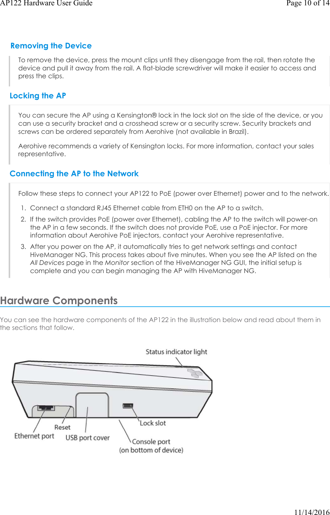
![Status LightThe status light conveys operational states for system power, firmware updates, Ethernet and wireless interface activity, and major alarms. The AP122 has a rectangular status light bar on the top corner and down one side of the chassis. The colors of this light bar indicate the following states of activity:Dark: There is no power or the status indicator is disabled.Amber (flashing): This is an alert that indicates that the device is performing a firmware upgrade. Do not power off the device during this process.Amber (steady): This is an alert that indicates that the CAPWAP connection has not been successfully established, or the device is booting or shutting down.White: The device is powered on, a successful CAPWAP connection has been made, and the firmware is operating normally. During normal operation, the LED produces a slow blink consisting of 4 seconds of illumination followed by one minute of darkness. To extend the life of the status LED, turn it off completely for normal use, and turn it on when needed for troubleshooting. To extend the life of the status LED, turn it off completely for normal use, and turn it on when needed for troubleshooting. To turn the LEDon or off or change the brightness using the CLI, enter: system led brightness [ bright | soft | dim | off]You can adjust the brightness level from bright (the default) to soft to dim, or turn it off completely in HiveManager NG. Navigate to Configure > Network Policy > Additional Settings>NetworkService > Management Options. Turn Management Options on and scroll down to the System Settings section. Use the LED brightness drop-down to select the brightness level that you want. When you change the brightness setting here, the new setting will apply to all devices under this network policy. To change the LED brightness for a single device, establish a console connection and use the CLI command.For devices running HiveManager Classic, you can set the LEDs for all APs on your network to blink or remain steady. Navigate toHome> Device Management Settings > LEDMode.Console PortThrough the Console port, you can make a serial connection between your management system and the AP. When you connect to the device using the RJ45 Console port, the management station from which you connect to the device must have a VT100 emulation program, such as Tera Term Pro© (a free terminal emulator) or Hilgraeve HyperTerminal® (provided with Windows® operating systems from XP forward). The serial connection settings are: 9600 bits per second, 8 data bits, no parity, 1 stop bit, no flow control. The pin-to-signal mapping for the Console port is shown in "Aerohive Device Pin Assignments".Page 11 of 14AP122 Hardware User Guide11/14/2016Component Descriptions](https://usermanual.wiki/Aerohive-Networks/AP122/User-Guide-3220091-Page-11.png)