Aerohive Networks AP122 Access Point User Manual AP122 Hardware User Guide
Aerohive Networks, Inc. Access Point AP122 Hardware User Guide
User Manual
AP122 Hardware User Guide
Read about and view specifications and compliance information for the AP122 in this topic. Install the
A
P122 using this topic
.
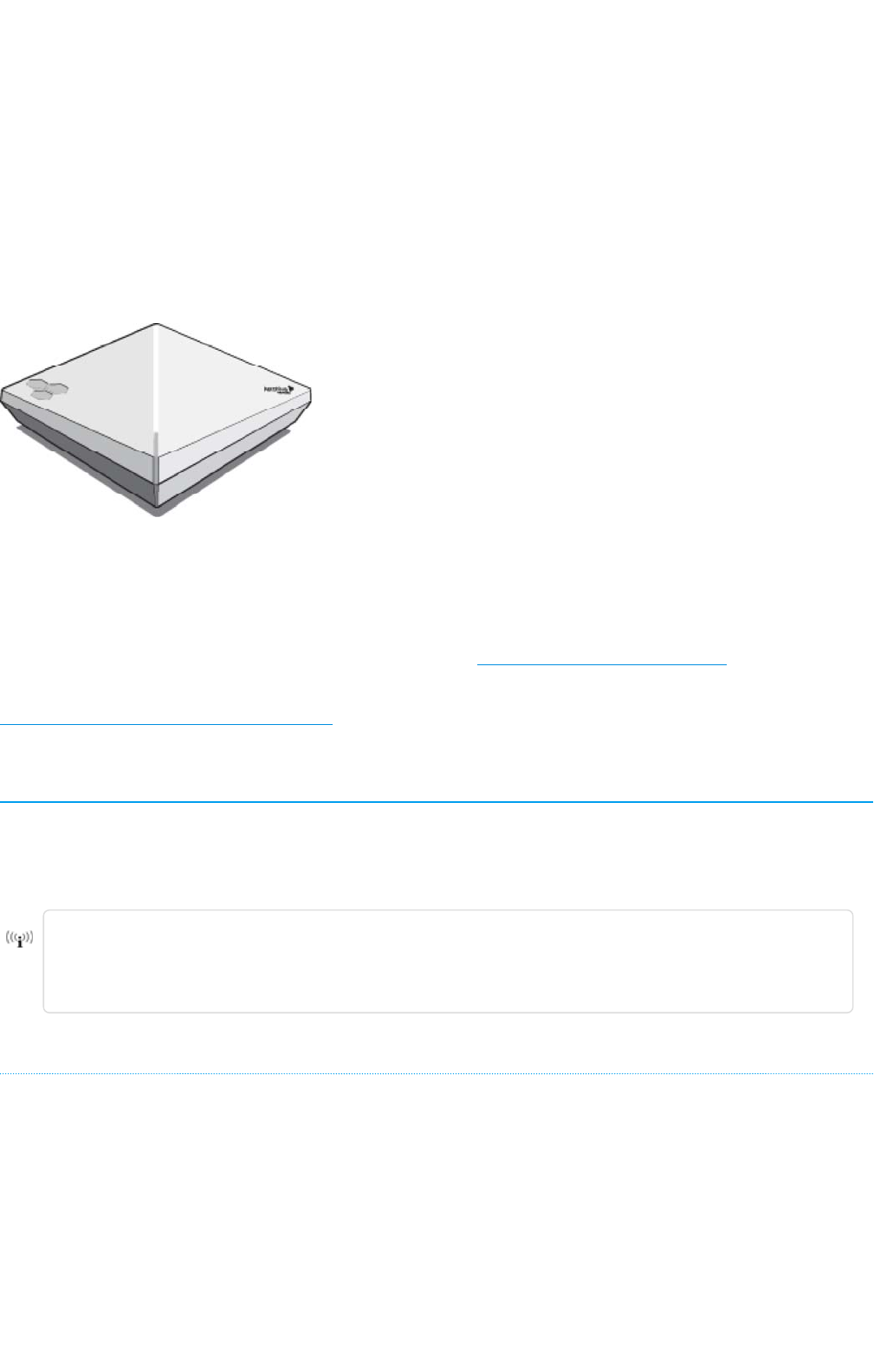
The AP122 is optimally suited for coverage-oriented, low-to-medium capacity environments. The AP122
features dual 2x2, 2-stream radios, providing dual 802.11n or 11n/ac performance with data rates up to
867 Mbps using existing 802.3af PoE infrastructure.
For more information about Aerohive APs in general, see "Introduction to Aerohive APs".
For information about connecting your APto the network, best-practices, and troubleshooting, see
"Basic Troubleshooting for New Devices"
Important! Changing the Country Code
If your access point is configured for the World Regulatory Domain, it is important to set the country
code to the country in which the APwill be deployed to meet regulatory requirements and for optimal
wireless operation. To do this, follow these steps:
The country code selection is for World models only and is not available to FCC, CAN, and
other country-specific models. Per FCC regulations, all Wi-Fi products marketed in the
United States must be set to U.S. channels only.
For Devices Running HiveManager:
1. Power on the APand allow it to find and connect to HiveManager. Once the APisconnected, it
appears in the table of unconfigured devices on the Monitor > Devices page and is categorized as
New under the Management Status table header.
2. Select the check box for the AP, and then choose Update > Advanced >Update Country.
3. On the Update Country Code page, choose the appropriate country code from the drop-down
list, and then click Upload.
Page 1 of 1
4
AP122 Hardware User Guid
e
11
/
14
/
201
6

For Devices Running HiveManager NG:
1. Power on the AP and allow it to find and connect to HiveManager NG. Once the APis connected
it appears in the table of devices on the Monitor > Devices page.
2. Select the check box next to the AP, and then choose Assign Country Code from the Actions drop-
down list. In the dialog box that appears, select the appropriate country from the drop-down list,
and then click Save.
3. Upload your changes to the device.
Regulatory Compliance Statements
The regulatory compliance statements in this section apply to AP122 devices.
For Japan, the AP122 is restricted for indoor use in the 5150-5350 MHz band only.
Compliance Statements
The following compliance information applies to the AP122.
R&TTE Directive
This device is compliant with the following directives:
• R&TTEDirective 1995/5/EC
AP122 Compliance Statement - Europe
EU Declaration of Conformity
This device complies with the essential requirements of the R&TTE Directive 1999/5/EC. The
following test methods have been applied in order to prove presumption of conformity with the
essential requirements of the R&TTE Directive 1999/5/EC:
IEC 60950-1:2005 +A1 +A2
Safety of Information Technology Equipment
EN 50385: / Article 3(1)(a) and Article 2 /EC)
Assessment of electronic and electrical equipment related to human exposure restrictions for
electromagnetic fields (0 Hz-300 GHz)
EN 300 328 V1.9.1:
Electromagnetic compatibility and Radio spectrum Matters (ERM); Wideband transmission
systems; Data transmission equipment operating using wide band modulation techniques;
Harmonized EN covering the essential requirements of article 3.2 of the R&TTE Directive
EN 301 893 V1.8.1:
Broadband Radio Access Networks (BRAN); 5 GHz high performance RLAN; Harmonized EN
covering the essential requirements of article 3.2 of the R&TTE Directive
Page 2 of 1
4
AP122 Hardware User Guid
e
11
/
14
/
201
6

EN 301 489-1 V1.9.2:
Electromagnetic compatibility and Radio spectrum Matters (ERM); Electromagnetic Compatibility
(EMC) standard for radio equipment and services; Part 1: Common technical requirements
EN 301 489-17 V2.2.1
Electromagnetic compatibility and Radio spectrum Matters (ERM); Electromagnetic Compatibility
(EMC) standard for radio equipment; Part 17: Specific conditions for Broadband Data Transmission
Systems
In Italy the end-user should apply for a license at the national spectrum authorities in order to
obtain authorization to use the device for setting up outdoor radio links and/or for supplying
public access to telecommunications and/or network services.
•Česky [Czech]: [Aerohive] tímto prohlašuje, že tento [AP122] je ve shodě se základními
požadavky a dalšími příslušnými ustanoveními směrnice 1999/5/ES.
•Dansk [Danish]: Undertegnede [Aerohive] erklærer herved, at følgende udstyr [AP122]
overholder de væsentlige krav og øvrige relevante krav i direktiv 1999/5/EF.
•Deutsch [German]: Hiermit erklärt [Aerohive], dass sich das Gerät [AP122] in
Übereinstimmung mit den grundlegenden Anforderungen und den übrigen einschlägigen
Bestimmungen der Richtlinie 1999/5/EG befindet.
•Eesti [Estonian]: Käesolevaga kinnitab [Aerohive] seadme [AP122] vastavust direktiivi
1999/5/EÜ põhinõuetele ja nimetatud direktiivist tulenevatele teistele asjakohastele sätetele.
•English: Hereby, [Aerohive], declares that this [AP122] is in compliance with the essential
requirements and other relevant provisions of Directive 1999/5/EC.
•Español [Spanish]: Por medio de la presente [Aerohive] declara que el [AP130] cumple con
los requisitos esenciales y cualesquiera otras disposiciones aplicables o exigibles de la
Directiva 1999/5/CE.
•Ελληνική [Greek]: ΜΕ ΤΗΝ ΠΑΡΟΥΣΑ [Aerohive] ΔΗΛΩΝΕΙ ΟΤΙ [AP122] ΣΥΜΜΟΡΦΩΝΕΤΑΙ
ΠΡΟΣ ΤΙΣ ΟΥΣΙΩΔΕΙΣ ΑΠΑΙΤΗΣΕΙΣ ΚΑΙ ΤΙΣ ΛΟΙΠΕΣ ΣΧΕΤΙΚΕΣ ΔΙΑΤΑΞΕΙΣ ΤΗΣ ΟΔΗΓΙΑΣ 1999/5/ΕΚ.
•Français [French]: Par la présente [Aerohive] déclare que l'appareil [AP130] est conforme
aux exigences essentielles et aux autres dispositions pertinentes de la directive 1999/5/CE.
•Italiano [Italian]: Con la presente [Aerohive] dichiara che questo [AP122] è conforme ai
requisiti essenziali ed alle altre disposizioni pertinenti stabilite dalla direttiva 1999/5/CE.
•Latviski [Latvian]: Ar šo [Aerohive] deklarē, ka [AP122] atbilst Direktīvas 1999/5/EK būtiskajām
prasībām un citiem ar to saistītajiem noteikumiem.
•Lietuvių [Lithuanian]: Šiuo [Aerohive] deklaruoja, kad šis [AP122] atitinka esminius reikalavimus
ir kitas 1999/5/EB Direktyvos nuostatas.
•Nederlands [Dutch]: Hierbij verklaart [Aerohive] dat het toestel [AP122] in overeenstemming
is met de essentiële eisen en de andere relevante bepalingen van richtlijn 1999/5/EG.
•Malti [Maltese]: Hawnhekk, [Aerohive], jiddikjara li dan [AP122] jikkonforma mal-ħtiġijiet
essenzjali u ma provvedimenti oħrajn relevanti li hemm fid-Dirrettiva 1999/5/EC.
•Magyar [Hungarian]: Alulírott, [Aerohive] nyilatkozom, hogy a [AP122] megfelel a vonatkozó
alapvetõ követelményeknek és az 1999/5/EC irányelv egyéb elõírásainak.
•Polski [Polish]: Niniejszym [Aerohive] oświadcza, że [AP122] jest zgodny z zasadniczymi
wymogami oraz pozostałymi stosownymi postanowieniami Dyrektywy 1999/5/EC.
•Português [Portuguese]: [Aerohive] declara que este [AP122] está conforme com os
requisitos essenciais e outras disposições da Directiva 1999/5/CE.
Page 3 of 1
4
AP122 Hardware User Guid
e
11
/
14
/
201
6

•Slovensko [Slovenian
]
: [Aerohive] izjavlja, da je ta [AP122] v skladu z bistvenimi zahtevami in
ostalimi relevantnimi določili direktive 1999/5/ES.
•Slovensky [Slovak]: [Aerohive] týmto vyhlasuje, že [AP122] spĺňa základné požiadavky a
všetky príslušné ustanovenia Smernice 1999/5/ES.
•Suomi [Finnish]: [Aerohive] vakuuttaa täten ettät [AP122] tyyppinen laite on direktiivin
1999/5/EY oleellisten vaatimusten ja sitä koskevien direktiivin muiden ehtojen mukainen.
Federal Communication Commission Interference Statement
This equipment has been tested and found to comply with the limits for a Class B digital device,
pursuant to Part 15 of the FCC Rules. These limits are designed to provide reasonable protection
against harmful interference in a residential installation. This equipment generates, uses and can
radiate radio frequency energy and, if not installed and used in accordance with the instructions,
may cause harmful interference to radio communications. However, there is no guarantee that
interference will not occur in a particular installation. If this equipment does cause harmful
interference to radio or television reception, which can be determined by turning the equipment
off and on, the user is encouraged to try to correct the interference by one of the following
measures:
• Reorient or relocate the receiving antenna.
• Increase the separation between the equipment and receiver.
• Connect the equipment into an outlet on a circuit different from that to which the receiver is
connected.
• Consult the dealer or an experienced radio/TV technician for help.
FCC Caution: Any changes or modifications not expressly approved by the party responsible for
compliance could void the user's authority to operate this equipment.
This device complies with Part 15 of the FCC Rules. Operation is subject to the following two
conditions: (1) This device may not cause harmful interference, and (2) this device must accept
any interference received, including interference that may cause undesired operation.
This device and its antenna(s) must not be co-located or operating in conjunction with any other
antenna or transmitter except in accordance with FCC multi-transmitter product procedures. If
this device operates in the 5.15~5.25 GHz frequency range, it is restricted to indoor use only.
IMPORTANT NOTE:
Radiation Exposure Statement:
This equipment complies with FCC radiation exposure limits set forth for an uncontrolled
environment. This equipment should be installed and operated with a minimum distance of
7.8" (20 cm) between the radiator people or animals.
This transmitter must not be co-located or operating in conjunction with any other antenna or
transmitter.
Canada Regulatory ISED Statements:
This device complies with ISED (Innovation, Science and Economic Development) Canada
license-exempt RSS standard(s). Operation is subject to the following two conditions:
1. This device may not cause interference, and
Page 4 of 1
4
AP122 Hardware User Guid
e
11
/
14
/
201
6

2
.
This device must accept any interference, including interference that may cause undesired
operation of the device.
Le présent appareil est conforme aux CNR d’ ISED Canada applicables aux appareils radio
exempts de licence. L'exploitation est autorisée aux deux conditions suivantes :
1. l'appareil ne doit pas produire de brouillage, et
2. l'utilisateur de l'appareil doit accepter tout brouillage radioélectrique subi, même si le
brouillage est susceptible d'en compromettre le fonctionnement.
For products available in the USA/Canada market, only channel 1~11 can be operated. Selection
of other channels is not possible.
Pour les produits disponibles aux États-Unis / Canada du marché, seul le canal 1 à 11 peuvent être
exploités. Sélection d'autres canaux n'est pas possible.
Caution:
(i) the device for operation in the band 5150-5250 MHz is only for indoor use to reduce the
potential for harmful interference to co-channel mobile satellite systems;
(ii) the maximum antenna gain permitted for devices in the bands 5250-5350 MHz and 5470-5725
MHz shall be such that the equipment still complies with the e.i.r.p. limit;
(iii) the maximum antenna gain permitted for devices in the band 5725-5850 MHz shall be such
that the equipment still complies with the e.i.r.p. limits specified for point-to-point and non-point-
to-point operation as appropriate; and
(iv) Users should also be advised that high-power radars are allocated as primary users (i.e. priority
users) of the bands 5250-5350 MHz and 5650-5850 MHz and that these radars could cause
interference and/or damage to LE-LAN devices.
Avertissement:
(i) les dispositifs fonctionnant dans la bande 5150-5250 MHz sont réservés uniquement pour une
utilisation à l’intérieur afin de réduire les risques de brouillage préjudiciable aux systèmes de
satellites mobiles utilisant les mêmes canaux;
(ii) le gain maximal d'antenne permis pour les dispositifs utilisant les bandes de 5250 à 5 350 MHz et
de 5470 à 5725 MHz doit être conforme à la limite de la p.i.r.e;
(iii) le gain maximal d'antenne permis (pour les dispositifs utilisant la bande de 5 725 à 5 850 MHz)
doit être conforme à la limite de la p.i.r.e. spécifiée pour l'exploitation point à point et
l’exploitation non point à point, selon le cas;
(iv) De plus, les utilisateurs devraient aussi être avisés que les utilisateurs de radars de haute
puissance sont désignés utilisateurs principaux (c.-à-d., qu’ils ont la priorité) pour les bandes 5250-
5350 MHz et 5650-5850 MHz et que ces radars pourraient causer du brouillage et/ou des
dommages aux dispositifs LAN-EL.
Radiation Exposure Statement:
This equipment complies with IC radiation exposure limits set forth for an uncontrolled
environment. This equipment should be installed and operated with minimum distance of 20 cm
between the radiator people and animals.
Page 5 of 1
4
AP122 Hardware User Guid
e
11
/
14
/
201
6

Déclaration d'exposition aux radiations:
Cet équipement est conforme aux limites d'exposition aux rayonnements IC établies pour un
environnement non contrôlé. Cet équipement doit être installé et utilisé avec un minimum de 20
cm de distance entre la source de rayonnement et des personnes ou des animaux.
Taiwan Compliance Information
Aerohive AP122
第十二條→經型式認證合格之低功率射頻電機,非經許可,公司,商號或使用者均不得擅自變更頻率、加大
功率或變更原設計之特性及功能。
第十四條→低功率射頻電機之使用不得影響飛航安全及干擾合法通信;經發現有干擾現象時,應立即停用,
並改善至無干擾時方得繼續使用。
前項合法通信,指依電信法規定作業之無線電通信。 低功率射頻電機須忍受合法通信或工業、科學及醫療
用電波輻射性電機設備之干擾。
在 5.25-5.35 秭赫頻帶內操作之無線資訊傳輸設備,限於室內使用。
無線資訊傳設備的製造廠商應確保頻率穩定性,如依製造廠商使用手冊上所述正常操作,發射的信號應維持
於操作頻帶中。
Taiwan MPE Warning
電磁波曝露量MPE標準值(MPE) 1mW/cm2,送測產品實值為0.734 mW/cm2
Radiation Exposure Statement:
This equipment complies with ISED RSS-102 radiation exposure limits set forth for an uncontrolled
environment. This equipment should be installed and operated with minimum distance 20 cm
(7.8") between the radiator, and people or animals.
Déclaration d'exposition aux radiations:
Cet équipement est conforme aux limites d'exposition aux rayonnements ISED établies pour un
environnement non contrôlé. Cet équipement doit être installé et utilisé avec un minimum de 20
cm de distance entre la source de rayonnement et des personnes ou des animaux.
Taiwan Compliance Information - Aerohive AP122
第十二條→經型式認證合格之低功率射頻電機,非經許可,公司,商號或使用者均不得擅自變更頻率、加大
功率或變更原設計之特性及功能。
第十四條→低功率射頻電機之使用不得影響飛航安全及干擾合法通信;經發現有干擾現象時,應立即停用,
並改善至無干擾時方得繼續使用。
前項合法通信,指依電信法規定作業之無線電通信。 低功率射頻電機須忍受合法通信或工業、科學及醫療
用電波輻射性電機設備之干擾。
在 5.25-5.35 秭赫頻帶內操作之無線資訊傳輸設備,限於室內使用。
Page 6 of 1
4
AP122 Hardware User Guid
e
11
/
14
/
201
6
無線資訊傳設備的製造廠商應確保
頻
率穩定性,如依製造廠商使用手冊上所述正常操作,發射的信號應維持
於操作頻帶中。
Taiwan MPE Warning - Aerohive AP122
電磁波曝露量MPE標準值(MPE) 1mW/cm2,送測產品實值為0.196868 mW/cm2
NCCStatement - Aerohive AP122
1. 「經型式認證合格之低功率射頻電機,非經許可,公司、商號或使用者均不得擅自變更頻率、加大功率
或變更原設計之特性及功能」。
2. 「低功率射頻電機之使用不得影響飛航安全及干擾合法通信;經發現有干擾現象時,應立即停用,並改
善至無干擾時方得繼續使用。前項合法通信,指依電信法規定作業之無線電通信。低功率射頻電機須忍
受合法通信或工業、科學及醫療用電波輻射性電機設備之干擾」。
3. 「不致造成違反低功率電波輻射性電機管理辦法之所有控制、調整及開關之使用方法」。
4. 「對任何可能造成違反管理辦法規定之調整予以警告,或建議由具有發射機維修專長之技術人員執行或
由其直接監督及負責」。
5. 「對任何可能造成違反管理辦法之零件(晶體、半導體等)置換之警告」。
6. 「電磁波曝露量MPE標準值1mW/cm2,送測產品實測值為:0.196868 mW/cm2」。
7. 「本器材須經專業工程人員安裝及設定,始得設置使用,且不得直接販售給一般消 費者」。
8. 「經型式認證合格之低功率射頻電機,非經許可,公司、商號或使用者均不得擅自變更頻率、加大功率
或變更原設計之特性及功能」。
Safety Guidelines
Safety Guidelines
The information in this section applies to AP122 devices.
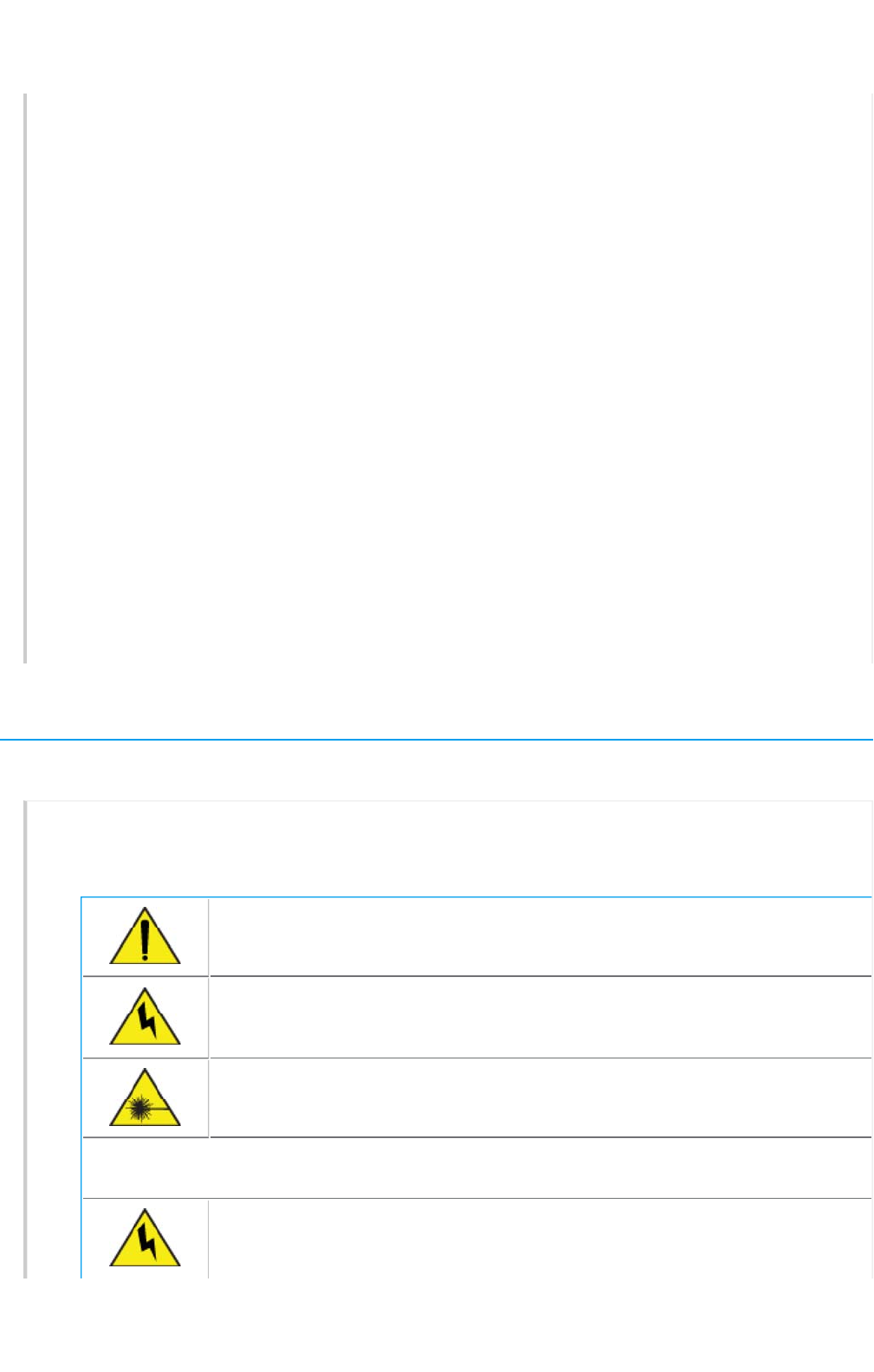
The following safety icons are used in these guidelines to identify the type of precaution:
This icon indicates a general caution. Failure to comply with a caution
notification can result in damage to equipment.
This icon indicates an electrical caution. Failure to comply with an electrical
notification can result in serious injury or death, and extensive damage to
equipment.
This icon indicates a laser caution. Failure to comply with a laser caution can
result in serious injury.
The following table lists the safety precautions you should follow when installing your AP122
devices.
Aerohive devices must be installed by a professional installer who is certified t
o
install these types of devices and to ensure that they are properly grounded
and meet applicable local and national electrical codes.
Page 7 of 1
4
AP122 Hardware User Guid
e
11
/
14
/
201
6
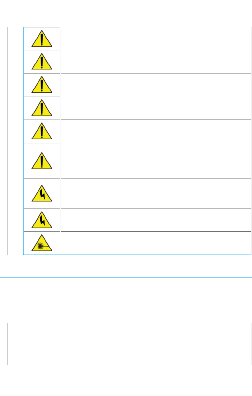
These devices are intended for indoor use only.
Do not install the device in an environment where the operating ambient
temperature might exceed the recommended ranges.
For products available in the USA/Canada market, for the 2.4 GHz band, only
channels 1-11 can be operated. Selection of other channels is not possible.
Changes or modifications made to this device that are not expressly approve
d
by the party responsible for compliance could void the user's authority to
operate the equipment.
Use only attachments and accessories specified by Aerohive.
These devices are not intended for use by persons (including children) with
reduced physical, sensory, or mental capabilities, or with lack of experience o
f
knowledge unless they are given supervision or instruction concerning use of t
h
devices by a person who is responsible for their safety. Children should be
supervised to ensure that they do not play with the devices.
Electrostatic discharge (ESD) can damage equipment and impair electrical
circuitry. ESD damage occurs when electronic components are improperly
handled and can result in complete or intermittent failures. Be sure to follow E
S
prevention procedures when handling electronic components and equipmen
During operation, the surfaces of the AP122 can become hot. Use caution wh
e
handling.
To meet federal radiation exposure requirements, these devices should be
installed at a minimum distance of 7.8" (20 cm) from people or animals.
Install the AP
You can mount the AP122 on a flat surface or wall, or on the rails of a standard dropped ceiling grid
using the hardware on the back of the chassis.
The following sections describe how to install your AP122 devices and connect them to the network.
Shipping Carton Contents
The AP122 access point shipping carton contains the following items:
• AP122 chassis
• Generic QuickStart Guide
• 3 wall-mount screws with anchors
Page 8 of 1
4
AP122 Hardware User Guid
e
11
/
14
/
201
6

Dropped Ceiling Mount
The following steps explain how to mount the AP122 on the rail of a dropped ceiling.
Make sure that you have all the materials and tools necessary, and familiarize yourself wit the
safety and site hazard warnings before you install the device. You may need to drill a small hole in
the adjacent ceiling tile to accommodate the cable. Before you begin, lift the ceiling tiles
adjacent to the location on the rail where you will install the device for better access. Once the
device is installed, you can slide it along the rail to better adjust its position.
Use the following steps to install your device to a dropped-ceiling rail.
1. For a dropped ceiling mount, use the mount tabs and clips on the bottom of the device.
2. Hold the device upside down and slip the mount tabs over the sides of the ceiling rail.
3. Press the device gently against the ceiling rail and rotate it until the mount clips click into
place.
Wall or Non-dropped Ceiling Mount
Use the built-in wall mount slots on the back of the chassis to attach the AP122 to any vertical or
horizontal surface (such as a wall or a drywall ceiling) that supports its weight (1.16 lb, or 0.56 kg),
and to which you can install wall mount screws. To mount the AP122 on a wall or other flat
surface, perform the following steps:
1. Make two marks where you want to mount the device on the wall or surface exactly 2.5" (64
cm) apart.
1. Drill two holes that are slightly smaller in diameter than the mounting screws.
2. Install two wall mount screws (and plastic anchors if necessary). The screw heads must
protrude far enough from the wall so that the chassis will slip over the screw heads, and leave
enough room to access the console connector. If you are connecting the device to cables
from inside the wall, drill an access hole for the cables.
3. Insert the heads of the screws into the large end of the wall mount slots and slide the device
down (or sideways for ceiling mounts) until the screws are seated in the narrow end of the
keyholes.
You can lock the device to the wall or ceiling using a security bracket that can be
ordered as an accessory.
4. To remove the device from the wall or ceiling, slide the chassis up until the screw heads slip
out of the wall mount slots.
5. The AP122 is PoE powered, so you must connect an Ethernet cable directly from the ETH0
port to a PoE-enabled switch or to a PoE injector.
You can also mount these devices to non-standard or recessed dropped ceiling tracks
using brackets designed for 9/16" (1.34 cm) tracks. These brackets can be ordered from
Aerohive (AH- ACC-BKT-80211AC-KIT). Not available in Brazil.
Page 9 of 1
4
AP122 Hardware User Guid
e
11
/
14
/
201
6
To remove the device, press the mount clips until they disengage from the rail, then rotate the
device and pull it away from the rail. A flat-blade screwdriver will make it easier to access and
press the clips.
Locking the AP
You can secure the AP using a Kensington® lock in the lock slot on the side of the device, or you
can use a security bracket and a crosshead screw or a security screw. Security brackets and
screws can be ordered separately from Aerohive (not available in Brazil).
Aerohive recommends a variety of Kensington locks. For more information, contact your sales
representative.
Connecting the AP to the Network
Follow these steps to connect your AP122 to PoE (power over Ethernet) power and to the network.
1. Connect a standard RJ45 Ethernet cable from ETH0 on the APto a switch.
2. If the switch provides PoE (power over Ethernet), cabling the APto the switch will power-on
the APin a few seconds. If the switch does not provide PoE, use a PoE injector. For more
information about Aerohive PoE injectors, contact your Aerohive representative.
3. After you power on the AP, it automatically tries to get network settings and contact
HiveManager NG. This process takes about five minutes. When you see the APlisted on the
All Devices page in the Monitor section of the HiveManager NG GUI, the initial setup is
complete and you can begin managing the AP with HiveManager NG.
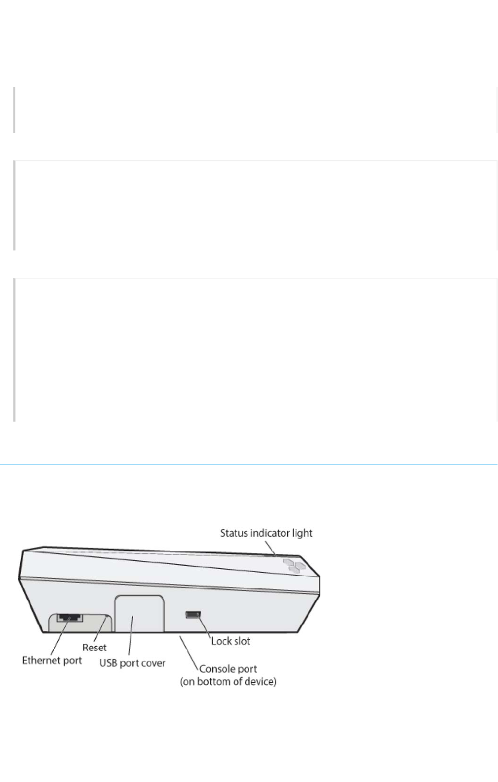
Hardware Components
You can see the hardware components of the AP122 in the illustration below and read about them in
the sections that follow.
Page 10 of 1
4
AP122 Hardware User Guid
e
11
/
14
/
201
6
Removing the Device
Status Light
The status light conveys operational states for system power, firmware updates, Ethernet and
wireless interface activity, and major alarms. The AP122 has a rectangular status light bar on the
top corner and down one side of the chassis. The colors of this light bar indicate the following
states of activity:
Dark: There is no power or the status indicator is disabled.
Amber (flashing): This is an alert that indicates that the device is performing a firmware
upgrade. Do not power off the device during this process.
Amber (steady): This is an alert that indicates that the CAPWAP connection has not been
successfully established, or the device is booting or shutting down.
White: The device is powered on, a successful CAPWAP connection has been made, and the
firmware is operating normally. During normal operation, the LED produces a slow blink
consisting of 4 seconds of illumination followed by one minute of darkness. To extend the life of
the status LED, turn it off completely for normal use, and turn it on when needed for
troubleshooting.
To extend the life of the status LED, turn it off completely for normal use, and turn it on when
needed for troubleshooting.
To turn the LEDon or off or change the brightness using the CLI, enter:
system led brightness [ bright | soft | dim | off]
You can adjust the brightness level from bright (the default) to soft to dim, or turn it off completely
in HiveManager NG. Navigate to Configure > Network Policy > Additional
Settings>NetworkService > Management Options. Turn Management Options on and scroll
down to the System Settings section. Use the LED brightness drop-down to select the brightness
level that you want.
When you change the brightness setting here, the new setting will apply to all devices
under this network policy. To change the LED brightness for a single device, establish a
console connection and use the CLI command.
For devices running HiveManager Classic, you can set the LEDs for all APs on your network to blink
or remain steady. Navigate toHome> Device Management Settings > LEDMode.
Console Port
Through the Console port, you can make a serial connection between your management system
and the AP. When you connect to the device using the RJ45 Console port, the management
station from which you connect to the device must have a VT100 emulation program, such as
Tera Term Pro© (a free terminal emulator) or Hilgraeve HyperTerminal® (provided with Windows®
operating systems from XP forward). The serial connection settings are: 9600 bits per second, 8
data bits, no parity, 1 stop bit, no flow control.
The pin-to-signal mapping for the Console port is shown in "Aerohive Device Pin Assignments".
Page 11 of 1
4
AP122 Hardware User Guid
e
11
/
14
/
201
6
Component Descriptions

You can power the AP122 through the ETH0 port from PSE (power sourcing equipment) that is
compatible with the 802.3af and 802.3at standards. Because there is no on/off switch, these
devices automatically power on when you connect them to power.
Ethernet Port
The AP122 has one RJ45 10/100/1000Base-T/TX Ethernet port (ETH0) that automatically negotiates
half- and full-duplex connections with the connecting device. The port is autosensing and adjusts
to straight-through and crossover standard Cat3, Cat5, Cat5e, or Cat6 Ethernet cables
automatically. The AP receives PoE power through an Ethernet connection to the ETH0 port from
PSE (power sourcing equipment) that is compatible with the 802.3at and 802.3af standards.
Power sourcing equipment can be embedded in a switch or router, or it can come from purpose-
built devices that inject power into the Ethernet line en route to the AP. Because the PoE port has
autosensing capabilities, the wiring termination in the Ethernet cable can be either straight-
through or crossover.
You can purchase your own PoE injector or purchase the following PoE injectors as optional
accessories from Aerohive (not available in Brazil):
• AH-ACC-INJ-20W-EU
•AH-ACC-INJ-20W-US
• AH-ACC-INJ-20W-AU
•AH-ACC-INJ-20W-IL
Reset Button
Use the Reset button to reset the device or restore the factory default settings. Insert a paper clip
or similar tool into the Reset pinhole and press the button. To reboot the device, press the button
for 5 seconds. To return the configuration to the factory default settings, press it for at least 10
seconds. After releasing the button, the indicator light goes dark, and then glows steady amber
while the firmware loads and the system performs a self-test. After the software finishes loading
and the AP has connected to HiveManager NG, the status indicator glows steady white.
To prevent the reset button from resetting the configuration, enter this command: no reset-
button reset-config-enable . When this command is enabled, pressing the button for 5
seconds will still reboot the AP, but pressing it for more than 10 seconds will not reset its
configuration.
Antennas
The AP122 has four internal single-band antennas. All antennas are omnidirectional and provide
fairly equal coverage in all directions.
Lock Slot
When mounting the AP on a ceiling track or flat surface, you can secure it to the track using a
Kensington® lock in the lock slot or using the security screw and bracket that ships with the
device. See "Locking the AP".
Page 1
2
of 1
4
AP122 Hardware User Guid
e
11
/
14
/
201
6
Power Connector

Hardware Specification
s
The following specifications describe the physical features and hardware components, the power
adapter and PoE electrical requirements, and the temperature and humidity ranges in which the
devices can operate.
Radio Specifications
802.11a
•5.150-5.850 GHz operating frequency
• Orthogonal Frequency Division Multiplexing (OFDM) modulation
• Rates (Mbps): 54, 48, 36, 24, 12, 9, 6 with auto fallback
802.11b
• 2.4-2.5 GHz operating frequency
• Direct-Sequence Spread-Spectrum (DSSS) modulation
• Rates (Mbps): 11, 5.5, 2. 1 with auto fallback
802.11g
• 2.4-2.5 GHz operating frequency
• Orthogonal Frequency Division Multiplexing (OFDM) modulation
• Rates (Mbps): 54, 48, 36, 24, 12, 9, 6 with auto fallback
802.11n
•2.4-2.5 and 5.150-5.850 GHz operating frequency
• 802.11n modulation
• Rates (Mbps): MCSO - MCS15 (6.5 Mbps - 300 Mbps)
• 2x2 MIMO radio
•HT20 and HT40 (5GHz) High-Throughput (HT) support
• A-MPDU and A-MSDU frame aggregation
802.11ac
•5.150-5.850 GHz operating frequency
• 802.11ac modulation (256-QAM)
• Rates (Mbps): MCSO - MCS9(6.5 Mbps - 867 Mbps), NSS = 1-2
• 2x2 stream MIMO radio
• VHT20/VHT40/VHT80 support
Device Specifications
• Chassis dimensions: 6.63” W x 2” H x 6.63” D (16.8 cm x 5 cm x 16.8 cm)
• Weight: 1.16 lbs (0.53 kg)
•Two internal 802.11b/g/n 2.4 GHz antennas , and two internal 802.11a/b/g/n/ac 5GHz
antennas
Page 1
3
of 1
4
AP122 Hardware User Guid
e
11
/
14
/
201
6

• One RJ45 (9600 bits per second, 8 data bits, no parity, 1 stop bit, no flow control
)
• Console serial port: RJ45 (9600 bits per second, 8 data bits, parity: none, 1 stop bit, no flow
control
• Eth0 Ethernet port: autosensing 10/100/1000Base-T/TX Mbps, with IEEE 802.3af- or 802.3at-
compliant PoE
Power Specifications
• PoE nominal input voltages: 48 V
• Typical PoE power consumption is 11 W
• RJ45 power input pins: Wires 4, 5, 7, 8 or 1, 2, 3, and 6
Environmental Specifications
• Operating temperature: 32° to 104° F (0° to 40° C)
• Storage temperature: -40° to 185° F (-40° to 85° C)
• Relative Humidity: 5 to 95% RH (noncondensing)
Aerohive Documentation Portal |Aerohive Blogs |Aerohive Community Forum
Copyright © 2016Aerohive Networks, Inc.
Page 1
4
of 1
4
AP122 Hardware User Guid
e
11
/
14
/
201
6
file:///C:/Users/dknodel/AppData/Local/Temp/MC_.ht
m