Aerohive Networks AP150W Access Point User Manual
Aerohive Networks, Inc. Access Point
UserManual.wiki
>
Aerohive Networks
>
AP150W User Manual
User Manual
Navigation menu
Upload a User Manual
Namespaces
Wiki Guide
HTML
PDF
Info
Views
User Manual
Discussion / Help
Navigation
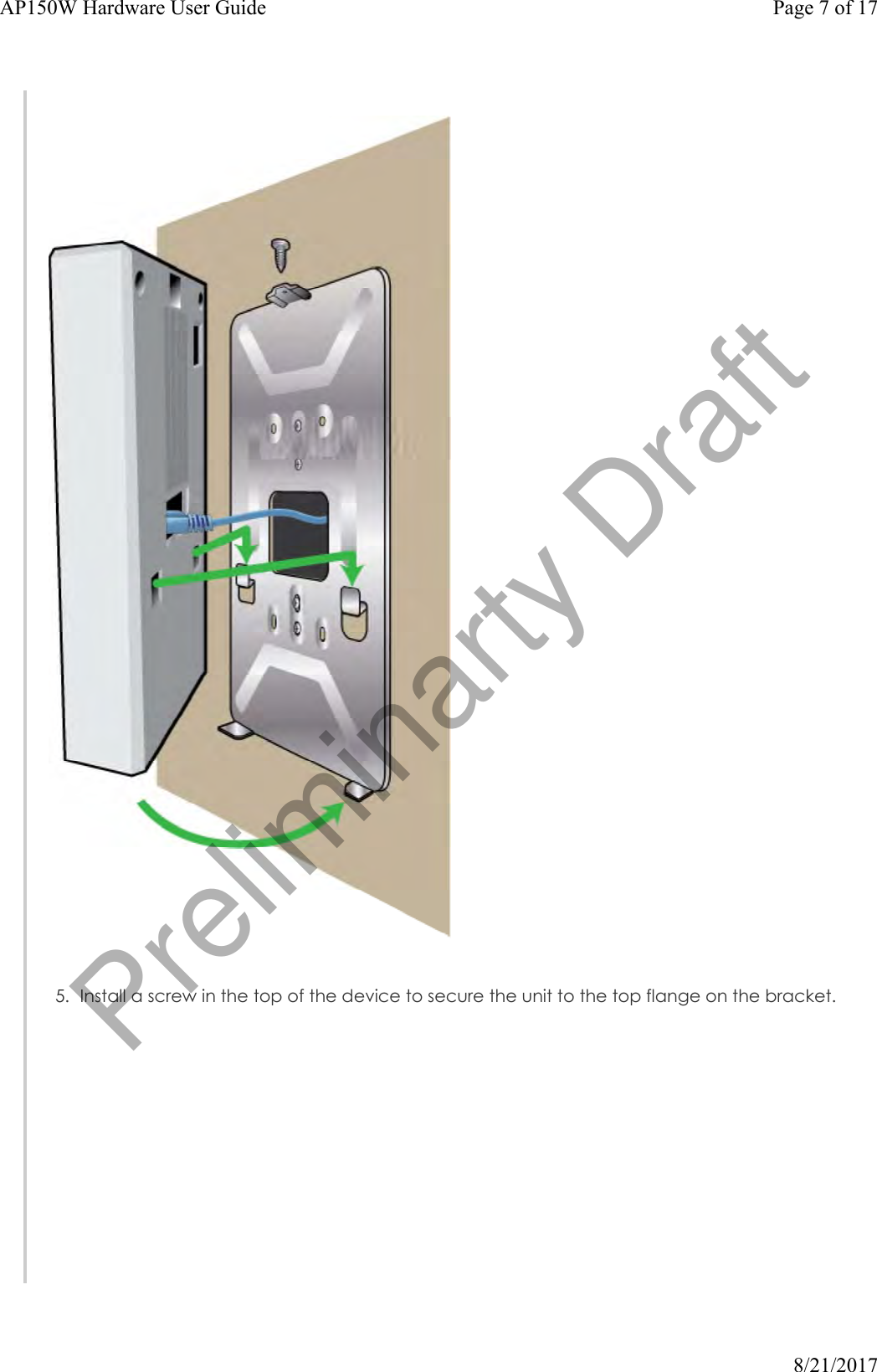
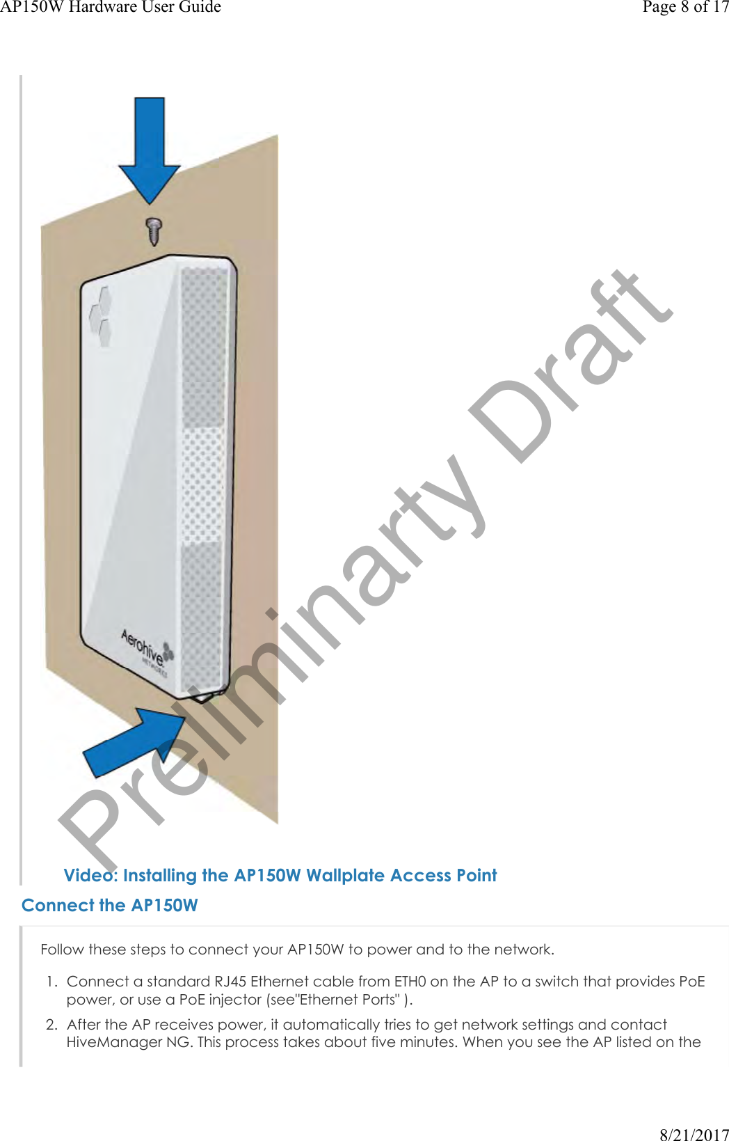
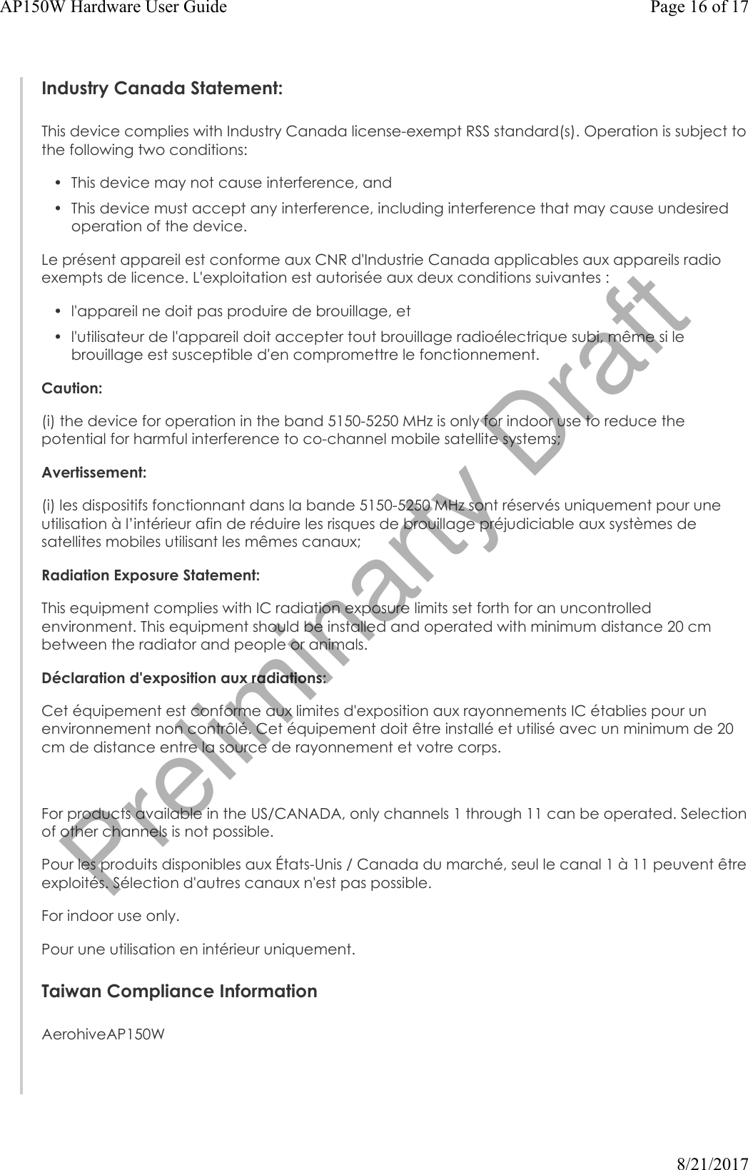
![Devices page in the Monitor section of the HiveManager NG GUI, the initial setup is complete and you can begin managing the AP with HiveManager NG.Hardware ComponentsYou can see the hardware components of the AP150W in the illustration below and read about them in the sections that follow.Component Descriptions Status LightThe status light conveys operational states for system power, firmware updates, Ethernet and wireless interface activity, and major alarms. The AP150W has a device status LED and an Ethernet port status LED.The device status LED is on the panel to the right of the Ethernet ports. The colors of this LED indicate the following states of activity:Dark: There is no power or the status indicator is disabled.Amber (flashing): This is an alert that indicates that the device is performing a firmware upgrade. Do not power off the device during this process.Amber (steady): This is an alert that indicates that the CAPWAP connection has not been successfully established, or the device is booting or shutting down.Green: The device is powered on, a successful CAPWAP connection has been made, and the firmware is operating normally. During normal operation, the LED produces a slow blink consisting of 4 seconds of illumination followed by one minute of darkness. To turn the LEDoff or on, or change the brightness using the CLI, enter: system led brightness [ bright | soft | dim | off]Page 9 of 17AP150W Hardware User Guide8/21/2017Preliminarty Draft](https://usermanual.wiki/Aerohive-Networks/AP150W/User-Guide-3527756-Page-9.png)
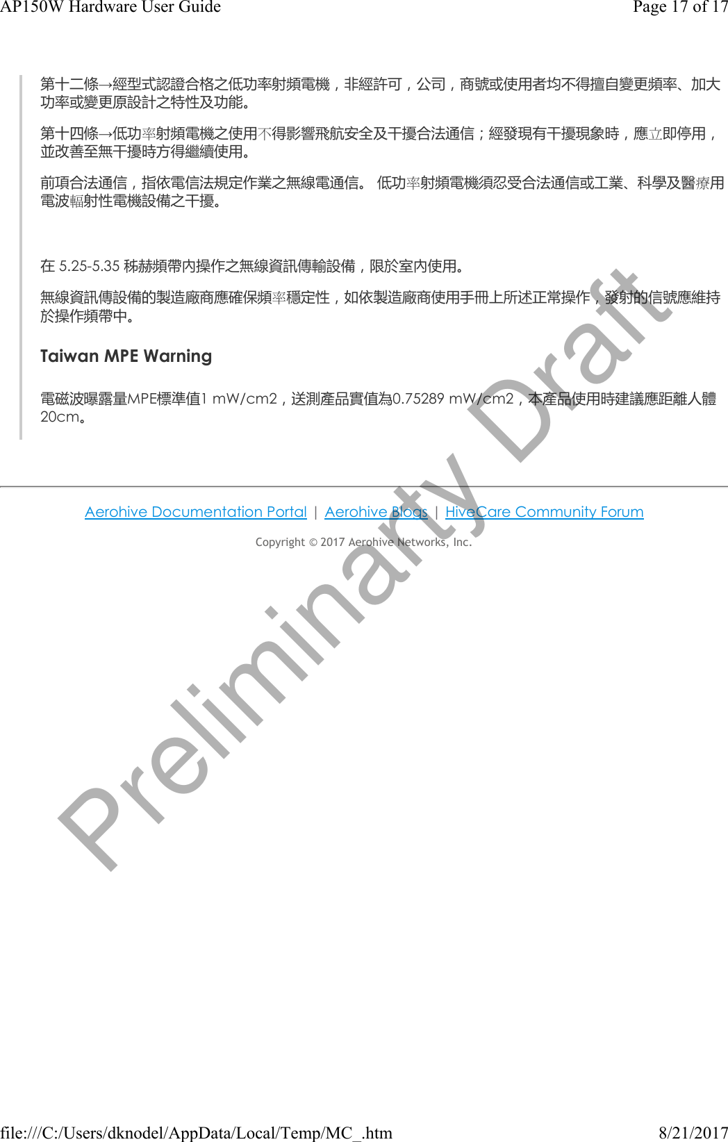
![(b) the words 'Restrictions or Requirements in', in a language easily understood by end- users as determined by the Member State concerned, followed by the abbreviations ofthe Member States, as prescribed in Annex II, where such restrictions or requirements exist.2. If radio equipment is subject to restrictions on putting into service or to requirements forauthorisation of use, as provided for in Article 10(10) of Directive 2014/53/EU, the instructionsaccompanying the radio equipment shall indicate, in a language easily understood by end-users as determined by the Member State concerned, the list of the Member States andgeographical areas within the Member States where such restrictions or requirements exist, aswell as the types of restrictions or requirements applicable in each Member State and eachgeographical area within a Member State.Article 3This Regulation shall enter into force on the twentieth day following that of its publication in the Official Journal of the European Union, and it shall apply as of …..[6 months after its entry into force]Radio equipment, which is placed on the market after [date: one day before the entry into force of this Regulation] and is in conformity with this Regulation, shall be deemed to be in conformity with Article 10(10) of Directive 2014/53/EU.This Regulation shall be binding in its entirety and directly applicable in all Member States. Done at Brussels,For the Commission The PresidentJean-Claude JunckerEU Declaration of ConformityThis device complies with the essential requirements of the R&TTE Directive 1999/5/EC. The following test methods have been applied in order to prove presumption of conformity with the essential requirements of the R&TTE Directive 1999/5/EC:EN 60950-1:2009 2006+A2:2013Safety of Information Technology EquipmentEN 62311: 2008 / Article 3(1)(a) and Article 2 2006/95/EC)Assessment of electronic and electrical equipment related to human exposure restrictions for electromagnetic fields (0 Hz-300 GHz)EN 300 328 V1.9.1: 2015-02Electromagnetic compatibility and Radio spectrum Matters (ERM); Wideband transmission systems; Data transmission equipment operating using wide band modulation techniques; Harmonized EN covering the essential requirements of article 3.2 of the R&TTE DirectiveEN 301 893 V1.8.1: 2015-03Broadband Radio Access Networks (BRAN); 5 GHz high performance RLAN; Harmonized EN covering the essential requirements of article 3.2 of the R&TTE DirectiveEN 301 489-1 V1.9.2: 2011Page 13 of 17AP150W Hardware User Guide8/21/2017Preliminarty Draft](https://usermanual.wiki/Aerohive-Networks/AP150W/User-Guide-3527756-Page-13.png)
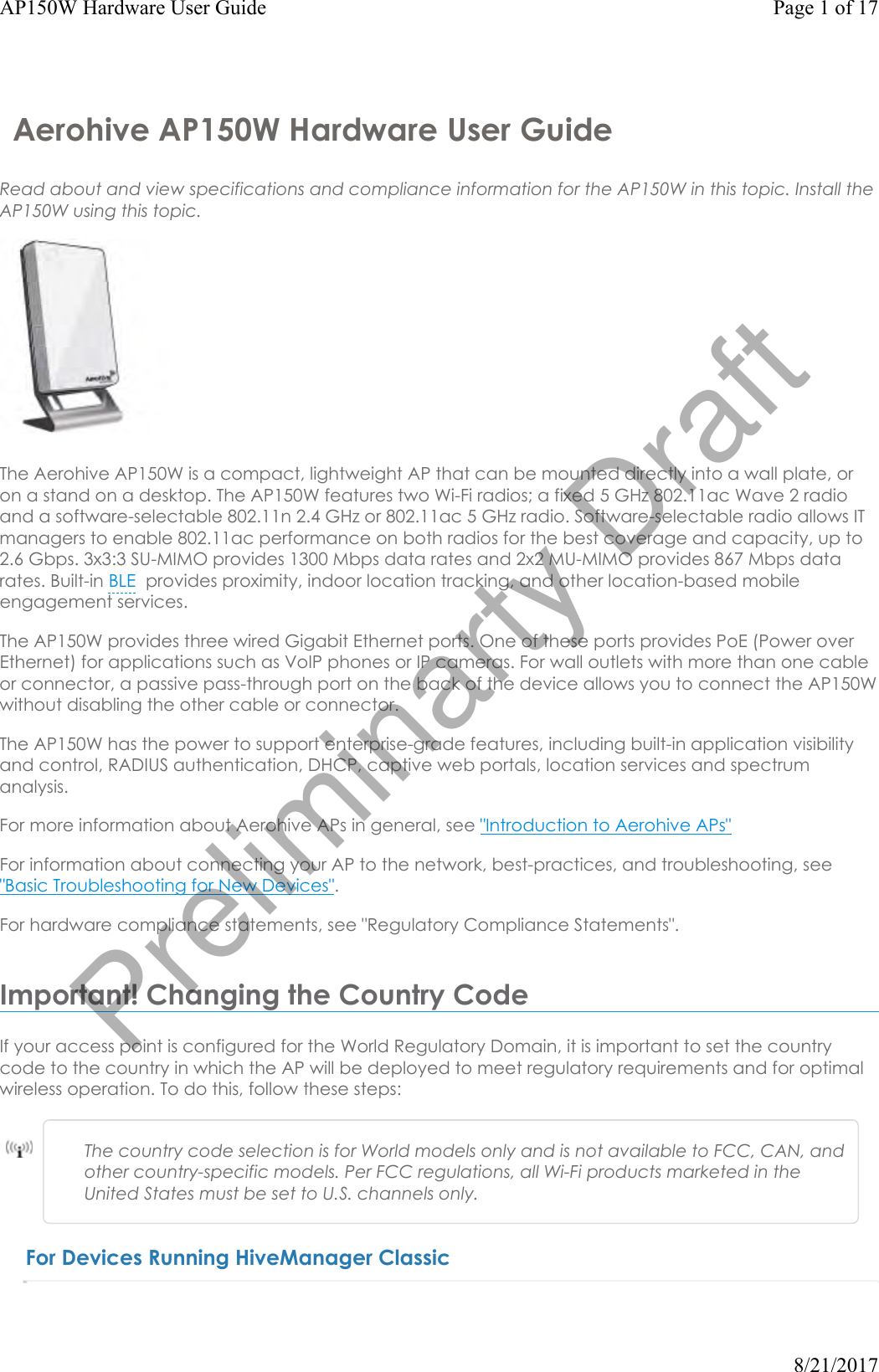
![Electromagnetic compatibility and Radio spectrum Matters (ERM); Electromagnetic Compatibility (EMC) standard for radio equipment and services; Part 1: Common technical requirementsEN 301 489-17 V2.2.1 2012Electromagnetic compatibility and Radio spectrum Matters (ERM); Electromagnetic Compatibility (EMC) standard for radio equipment; Part 17: Specific conditions for Broadband Data Transmission SystemsIn Italy the end-user should apply for a license at the national spectrum authorities in order to obtain authorization to use the device for setting up outdoor radio links and/or for supplying public access to telecommunications and/or network services.•Česky [Czech]: [Aerohive] tímto prohlašuje, že tento [AP150W] je ve shodě se základnímipožadavky a dalšími příslušnými ustanoveními směrnice 1999/5/ES.•Dansk [Danish]: Undertegnede [Aerohive] erklærer herved, at følgende udstyr [AP150W]overholder de væsentlige krav og øvrige relevante krav i direktiv 1999/5/EF.•Deutsch [German]: Hiermit erklärt [Aerohive], dass sich das Gerät [AP150W] inÜbereinstimmung mit den grundlegenden Anforderungen und den übrigen einschlägigenBestimmungen der Richtlinie 1999/5/EG befindet.•Eesti [Estonian]: Käesolevaga kinnitab [Aerohive] seadme [AP150W] vastavust direktiivi1999/5/EÜ põhinõuetele ja nimetatud direktiivist tulenevatele teistele asjakohastele sätetele.•English: Hereby, [Aerohive], declares that this [AP150W] is in compliance with the essentialrequirements and other relevant provisions of Directive 1999/5/EC.•Español [Spanish]: Por medio de la presente [Aerohive] declara que el [AP150W] cumplecon los requisitos esenciales y cualesquiera otras disposiciones aplicables o exigibles de laDirectiva 1999/5/CE.•Ελληνική [Greek]: ΜΕ ΤΗΝ ΠΑΡΟΥΣΑ [Aerohive] ΔΗΛΩΝΕΙ ΟΤΙ [AP150W] ΣΥΜΜΟΡΦΩΝΕΤΑΙΠΡΟΣ ΤΙΣ ΟΥΣΙΩΔΕΙΣ ΑΠΑΙΤΗΣΕΙΣ ΚΑΙ ΤΙΣ ΛΟΙΠΕΣ ΣΧΕΤΙΚΕΣ ΔΙΑΤΑΞΕΙΣ ΤΗΣ ΟΔΗΓΙΑΣ 1999/5/ΕΚ.•Français [French]: Par la présente [Aerohive] déclare que l'appareil [AP150W] est conformeaux exigences essentielles et aux autres dispositions pertinentes de la directive 1999/5/CE.•Italiano [Italian]: Con la presente [Aerohive] dichiara che questo [AP150W] è conforme airequisiti essenziali ed alle altre disposizioni pertinenti stabilite dalla direttiva 1999/5/CE.•Latviski [Latvian]: Ar šo [Aerohive] deklarē, ka [AP150W] atbilst Direktīvas 1999/5/EKbūtiskajām prasībām un citiem ar to saistītajiem noteikumiem.•Lietuvių [Lithuanian]: Šiuo [Aerohive] deklaruoja, kad šis [AP150W] atitinka esminiusreikalavimus ir kitas 1999/5/EB Direktyvos nuostatas.•Nederlands [Dutch]: Hierbij verklaart [Aerohive] dat het toestel [AP150W] inovereenstemming is met de essentiële eisen en de andere relevante bepalingen van richtlijn1999/5/EG.•Malti [Maltese]: Hawnhekk, [Aerohive], jiddikjara li dan [AP150W] jikkonforma mal-ħtiġijietessenzjali u ma provvedimenti oħrajn relevanti li hemm fid-Dirrettiva 1999/5/EC.•Magyar [Hungarian]: Alulírott, [Aerohive] nyilatkozom, hogy a [AP150W] megfelel avonatkozó alapvetõ követelményeknek és az 1999/5/EC irányelv egyéb elõírásainak.•Polski [Polish]: Niniejszym [Aerohive] oświadcza, że [AP150W] jest zgodny z zasadniczymiwymogami oraz pozostałymi stosownymi postanowieniami Dyrektywy 1999/5/EC.•Português [Portuguese]: [Aerohive] declara que este [AP150W] está conforme com osrequisitos essenciais e outras disposições da Directiva 1999/5/CE.Page 14 of 17AP150W Hardware User Guide8/21/2017Preliminarty Draft](https://usermanual.wiki/Aerohive-Networks/AP150W/User-Guide-3527756-Page-14.png)
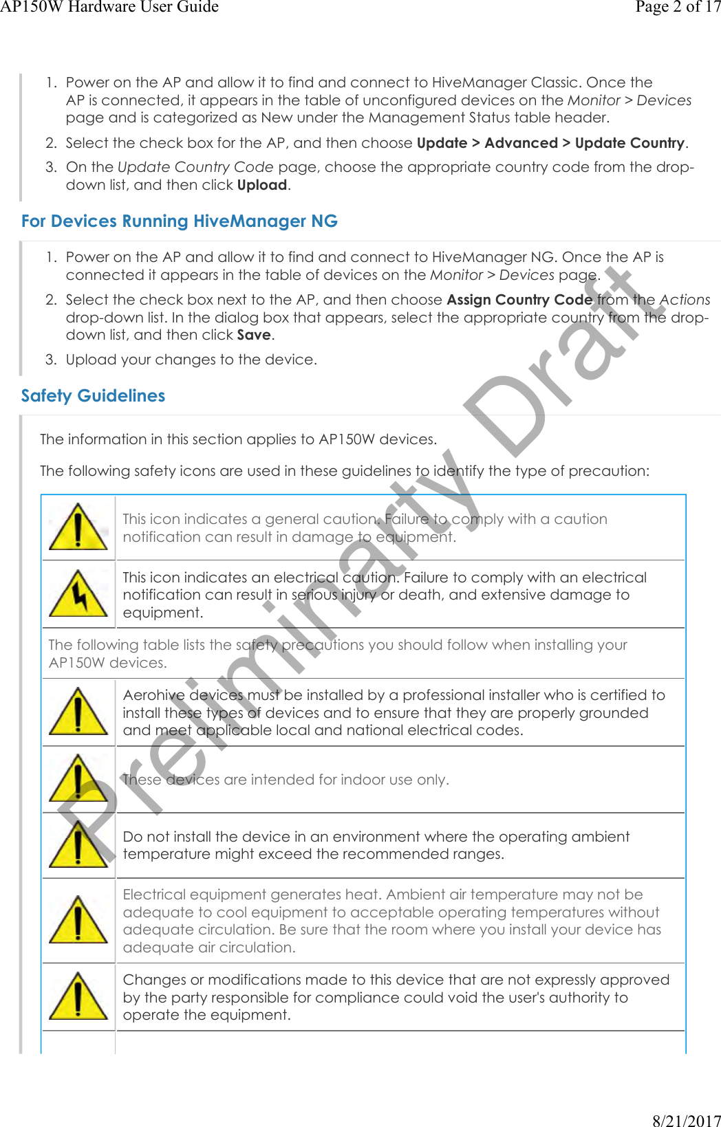
![•Slovensko [Slovenian]: [Aerohive] izjavlja, da je ta [AP150W] v skladu z bistvenimi zahtevamiin ostalimi relevantnimi določili direktive 1999/5/ES.•Slovensky [Slovak]: [Aerohive] týmto vyhlasuje, že [AP150W] spĺňa základné požiadavky avšetky príslušné ustanovenia Smernice 1999/5/ES.•Suomi [Finnish]: [Aerohive] vakuuttaa täten että [AP150W] tyyppinen laite on direktiivin1999/5/EY oleellisten vaatimusten ja sitä koskevien direktiivin muiden ehtojen mukainen.EURadiation Warning StatementTo meet radiation exposure requirements, these devices should be installed at a minimum distance of 8" (20 cm) from people or animals.Federal Communication Commission Interference StatementThis equipment has been tested and found to comply with the limits for a Class B digital device, pursuant to Part 15 of the FCC Rules. These limits are designed to provide reasonable protection against harmful interference in a residential installation. This equipment generates, uses and can radiate radio frequency energy and, if not installed and used in accordance with the instructions, may cause harmful interference to radio communications. However, there is no guarantee that interference will not occur in a particular installation. If this equipment does cause harmful interference to radio or television reception, which can be determined by turning the equipment off and on, the user is encouraged to try to correct the interference by one of the following measures:• Reorient or relocate the receiving antenna.• Increase the separation between the equipment and receiver.• Connect the equipment into an outlet on a circuit different from that to which the receiver isconnected.• Consult the dealer or an experienced radio or TV technician for help.FCC Caution: Any changes or modifications not expressly approved by the party responsible for compliance could void the user's authority to operate this equipment.This device complies with Part 15 of the FCC Rules. Operation is subject to the following two conditions: (1) This device may not cause harmful interference, and (2) this device must accept any interference received, including interference that may cause undesired operation.IMPORTANT NOTE:Radiation Exposure Statement:This equipment complies with FCC radiation exposure limits set forth for an uncontrolled environment. This equipment should be installed and operated with minimum distance 8" (20 cm) between the radiator and people or animals.This transmitter must not be co-located or operating in conjunction with any other antenna or transmitter.Country Code selection feature to be disabled for products marketed to the US/CANADA.For products available in the US/CANADA, only channels 1 through 11 can be operated. Selection of other channels is not possible. This device is for indoor use only.Page 15 of 17AP150W Hardware User Guide8/21/2017Preliminarty Draft](https://usermanual.wiki/Aerohive-Networks/AP150W/User-Guide-3527756-Page-15.png)