Aerohive Networks AP150W Access Point User Manual
Aerohive Networks, Inc. Access Point
User Manual
Aerohive AP150W Hardware User Guide
Read about and view specifications and compliance information for the AP150W in this topic. Install the
A
P150W using this topic
.
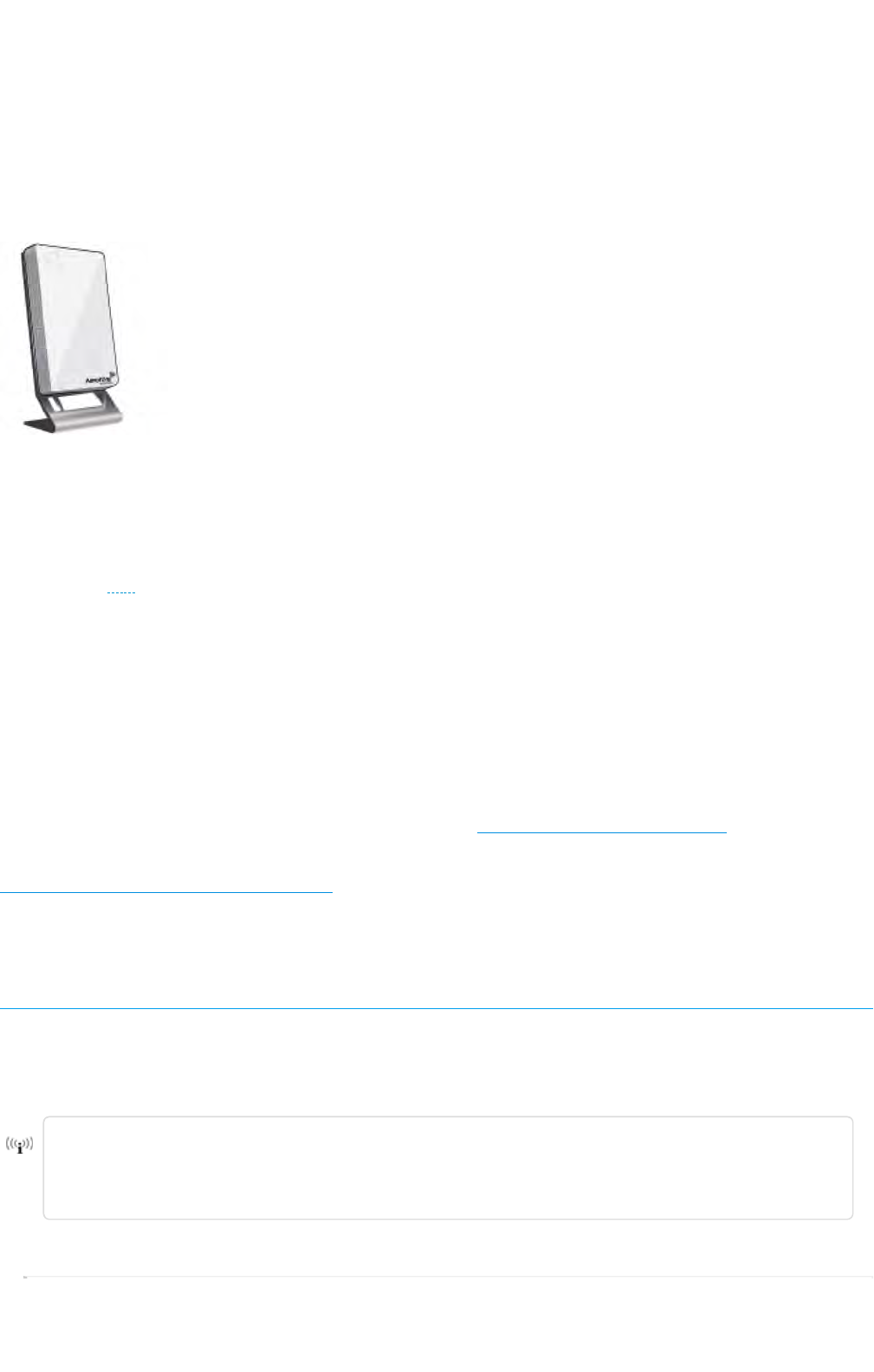
The Aerohive AP150W is a compact, lightweight AP that can be mounted directly into a wall plate, or
on a stand on a desktop. The AP150W features two Wi-Fi radios; a fixed 5 GHz 802.11ac Wave 2 radio
and a software-selectable 802.11n 2.4 GHz or 802.11ac 5 GHz radio. Software-selectable radio allows IT
managers to enable 802.11ac performance on both radios for the best coverage and capacity, up to
2.6 Gbps. 3x3:3 SU-MIMO provides 1300 Mbps data rates and 2x2 MU-MIMO provides 867 Mbps data
rates. Built-in BLE provides proximity, indoor location tracking, and other location-based mobile
engagement services.
The AP150W provides three wired Gigabit Ethernet ports. One of these ports provides PoE (Power over
Ethernet) for applications such as VoIP phones or IPcameras. For wall outlets with more than one cable
or connector, a passive pass-through port on the back of the device allows you to connect the AP150W
without disabling the other cable or connector.
The AP150W has the power to support enterprise-grade features, including built-in application visibility
and control, RADIUS authentication, DHCP, captive web portals, location services and spectrum
analysis.
For more information about Aerohive APs in general, see "Introduction to Aerohive APs"
For information about connecting your APto the network, best-practices, and troubleshooting, see
"Basic Troubleshooting for New Devices".
For hardware compliance statements, see "Regulatory Compliance Statements".
Important! Changing the Country Code
If your access point is configured for the World Regulatory Domain, it is important to set the country
code to the country in which the APwill be deployed to meet regulatory requirements and for optimal
wireless operation. To do this, follow these steps:
The country code selection is for World models only and is not available to FCC, CAN, and
other country-specific models. Per FCC regulations, all Wi-Fi products marketed in the
United States must be set to U.S. channels only.
For Devices Running HiveManager Classic
Page 1 of 1
7
AP150W Hardware User Guid
e
8
/
21
/
201
7
Preliminarty Draft
1
.
Power on the APand allow it to find and connect to HiveManager Classic. Once the
APisconnected, it appears in the table of unconfigured devices on the Monitor > Devices
page and is categorized as New under the Management Status table header.
2. Select the check box for the AP, and then choose Update > Advanced >Update Country.
3. On the Update Country Code page, choose the appropriate country code from the drop-
down list, and then click Upload.
For Devices Running HiveManager NG
1. Power on the AP and allow it to find and connect to HiveManager NG. Once the APis
connected it appears in the table of devices on the Monitor > Devices page.
2. Select the check box next to the AP, and then choose Assign Country Code from the Actions
drop-down list. In the dialog box that appears, select the appropriate country from the drop-
down list, and then click Save.
3. Upload your changes to the device.
Safety Guidelines
The information in this section applies to AP150W devices.
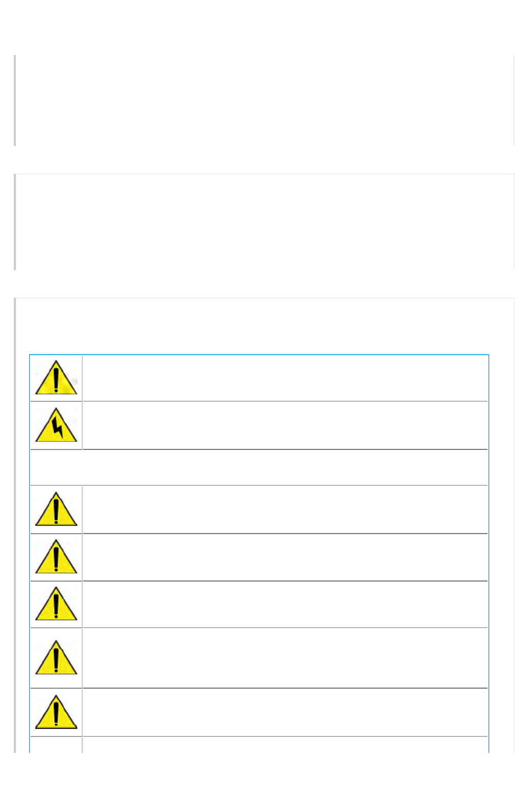
The following safety icons are used in these guidelines to identify the type of precaution:
This icon indicates a general caution. Failure to comply with a caution
notification can result in damage to equipment.
This icon indicates an electrical caution. Failure to comply with an electrical
notification can result in serious injury or death, and extensive damage to
equipment.
The following table lists the safety precautions you should follow when installing your
AP150W devices.
Aerohive devices must be installed by a professional installer who is certified to
install these types of devices and to ensure that they are properly grounded
and meet applicable local and national electrical codes.
These devices are intended for indoor use only.
Do not install the device in an environment where the operating ambient
temperature might exceed the recommended ranges.
Electrical equipment generates heat. Ambient air temperature may not be
adequate to cool equipment to acceptable operating temperatures without
adequate circulation. Be sure that the room where you install your device has
adequate air circulation.
Changes or modifications made to this device that are not expressly approved
by the party responsible for compliance could void the user's authority to
operate the equipment.
Page 2 of 1
7
AP150W Hardware User Guid
e
8
/
21
/
201
7
Preliminarty Draft
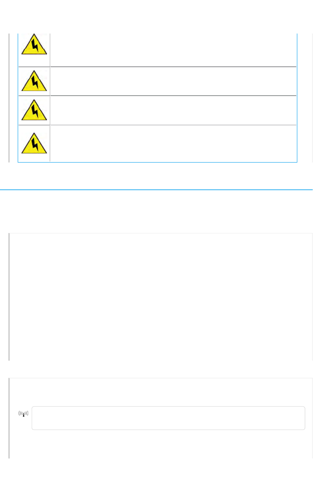
Electrostatic discharge (ESD) can damage equipment and impair electrical
circuitry. ESD damage occurs when electronic components are improperly
handled and can result in complete or intermittent failures. Be sure to follow
ESD-prevention procedures when handling electronic components.
Never assume that power is disconnected from a circuit; always check the
circuit.
To meet radiation exposure requirements in all countries, these devices should
be installed at a minimum distance of 9.05" (23 cm) from people and animals.
See individual country warning for country-specific distances, if required.
All Ethernet and RS232 (console) ports and the cables attached to them are
designed for intra-building connection to other equipment. Do not connect
these ports directly to wiring that exits the building where this appliance is
located
Install the AP150W
The following sections describe how to install your AP150W devices, connect them to the network, and
start managing them in HiveManager NG.
Shipping Carton Contents
The AP150W access point shipping carton contains the following items:
• AP150W chassis
• Generic QuickStart Card
• Wall mounting bracket and mounting hardware packet containing four Phillips screws and
one Torx screw.
•Ethernet cable
Video:Unboxing the AP150W Wallplate Access Point
For mounting instructions, see "Mount the AP150W ".
For information about securing the device, see "Secure the AP150W".
For information about the status indicator light, see "Status Light".
Mount the AP150W to a Wall
Use the following instructions to mount the AP150W directly to an Ethernet cable receptacle box
in a wall.
The mounting bracket has holes for several types of wall receptacles. The holes are
labeled as shown below: UK/EU, US/DUAL, and US/SINGLE.
Page 3 of 1
7
AP150W Hardware User Guid
e
8
/
21
/
201
7
Preliminarty Draft
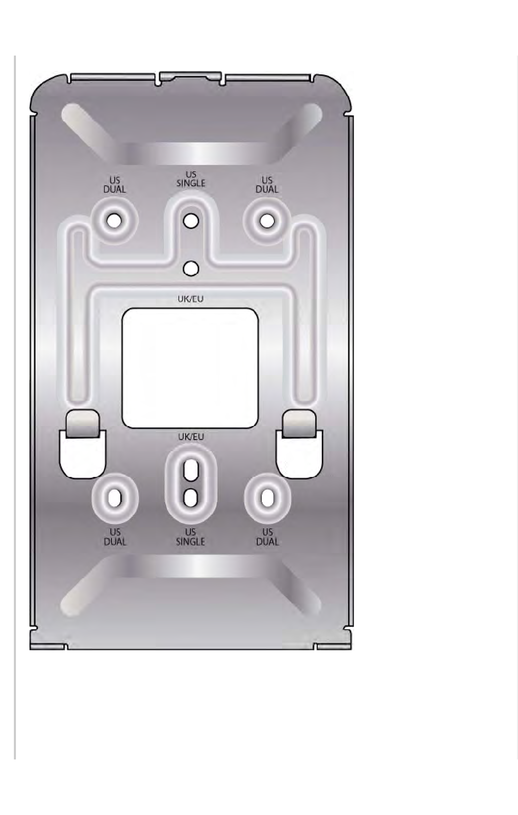
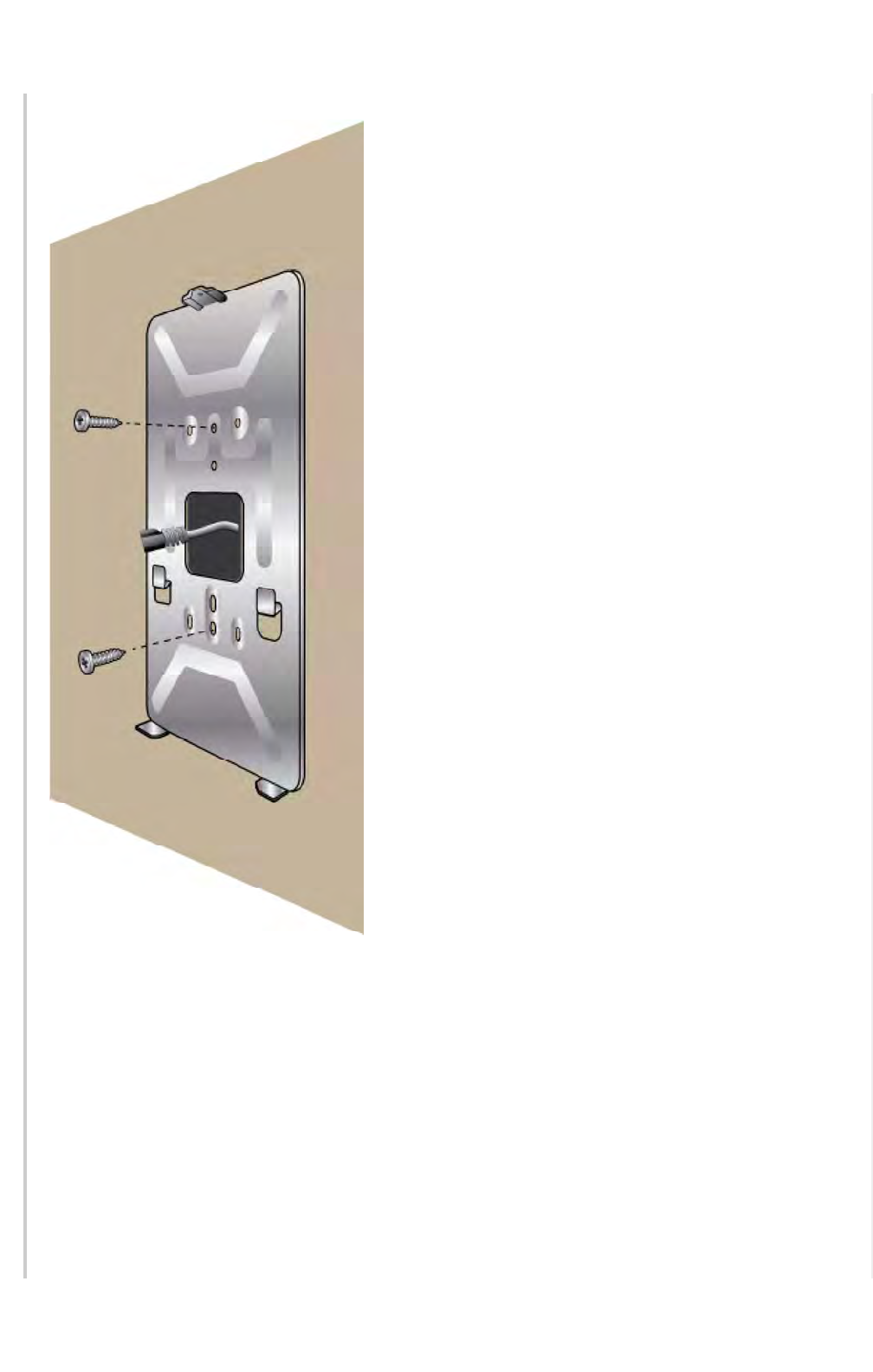
1. Remove the wall outlet covering.
2. Attach the wall bracket to the wall with the large opening in the bracket aligned to the hole
in the wall. Use at least two mounting screws to mount the bracket. The illustration below
shows a bracket for a US/SINGLE wall socket.
Page 4 of 1
7
AP150W Hardware User Guid
e
8
/
21
/
201
7
Preliminarty Draft
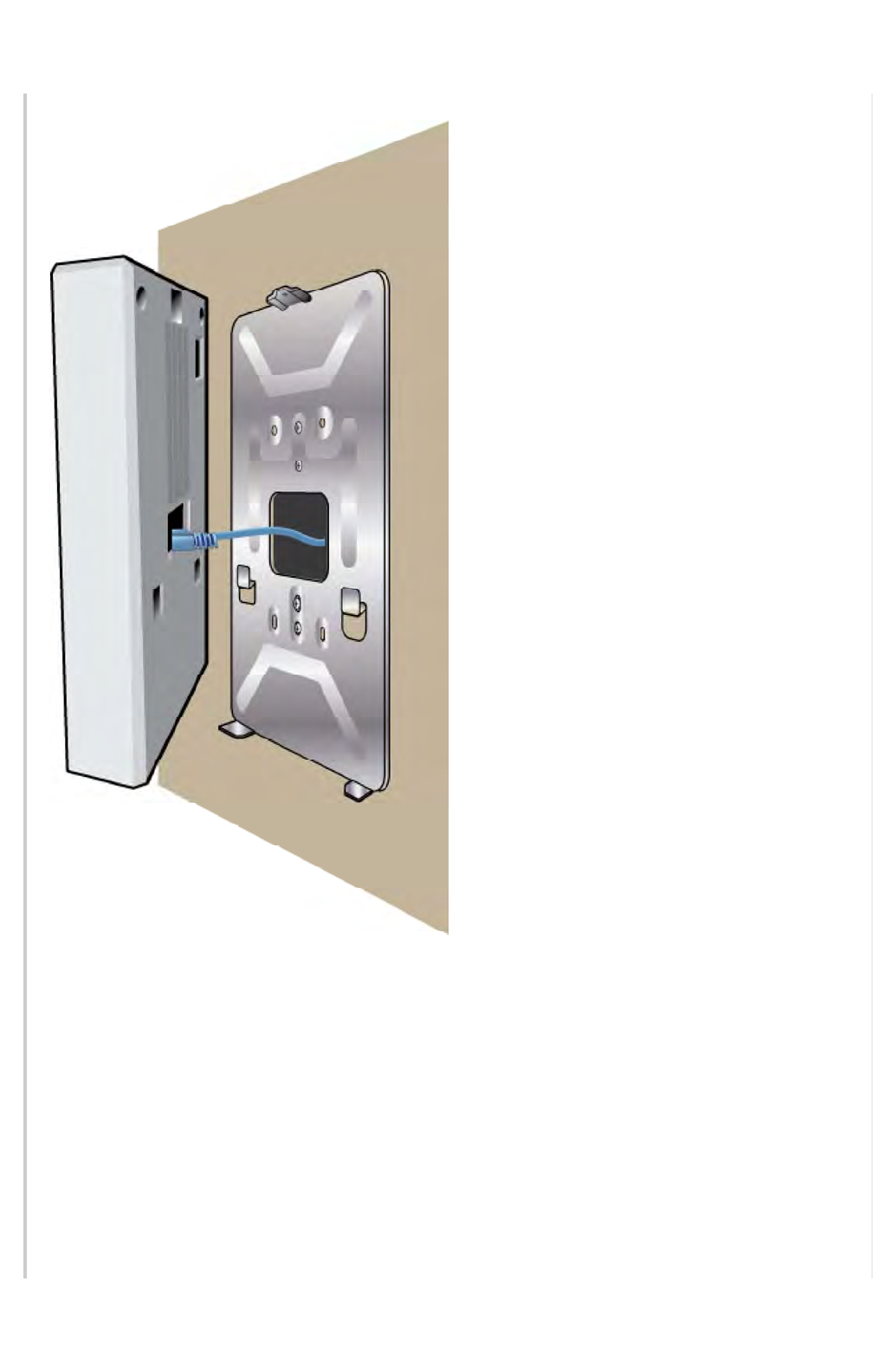
3. If necessary, use the short Ethernet cable that ships with the device to connect the Eth0 port
on the back of your device to the jack in the wall.
Page 5 of 1
7
AP150W Hardware User Guid
e
8
/
21
/
201
7
Preliminarty Draft
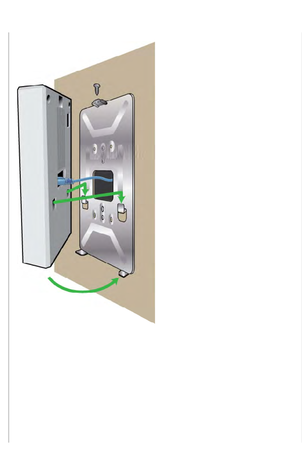
4. Attach the device to the bracket by inserting the two tabs on the bracket into the holes in
the back of the device, and the flange on top of the bracket onto the opening at the top of
the device back panel. Push down on the device to seat it on the bracket, as shown in the
illustration. The device will rest on the two flanges at the bottom of the bracket.
Page 6 of 1
7
AP150W Hardware User Guid
e
8
/
21
/
201
7
Preliminarty Draft
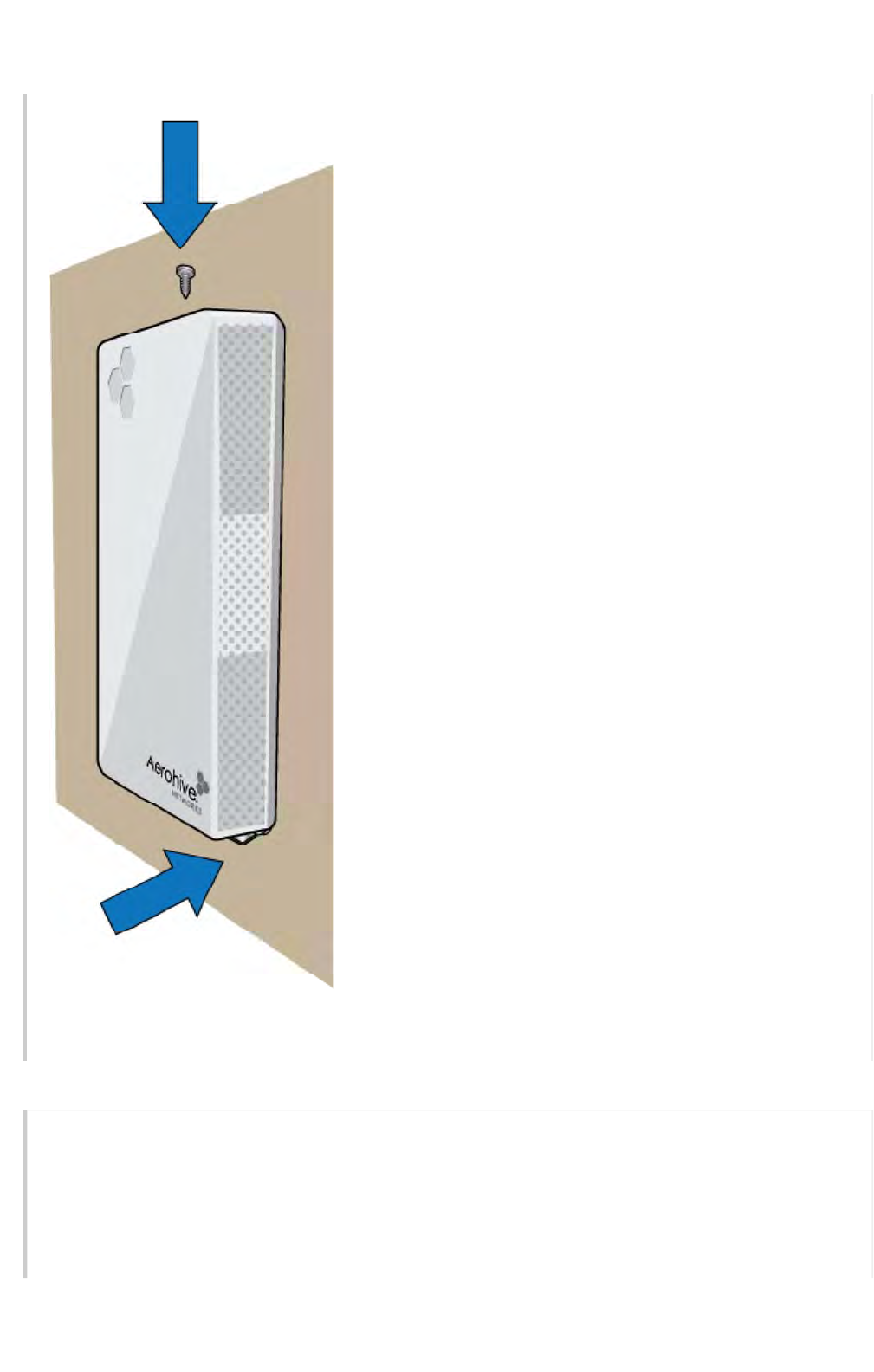
5. Install a screw in the top of the device to secure the unit to the top flange on the bracket.
Page 7 of 1
7
AP150W Hardware User Guid
e
8
/
21
/
201
7
Preliminarty Draft
Video: Installing the AP150W Wallplate Access Point
Connect the AP150W
Follow these steps to connect your AP150W to power and to the network.
1. Connect a standard RJ45 Ethernet cable from ETH0 on the APto a switch that provides PoE
power, or use a PoE injector (see"Ethernet Ports" ).
2. After the AP receives power, it automatically tries to get network settings and contact
HiveManager NG. This process takes about five minutes. When you see the APlisted on the
Page 8 of 1
7
AP150W Hardware User Guid
e
8
/
21
/
201
7
Preliminarty Draft
Devices page in the
M
onitor section of the HiveManager NG GUI, the initial setup is complete
and you can begin managing the AP with HiveManager NG.
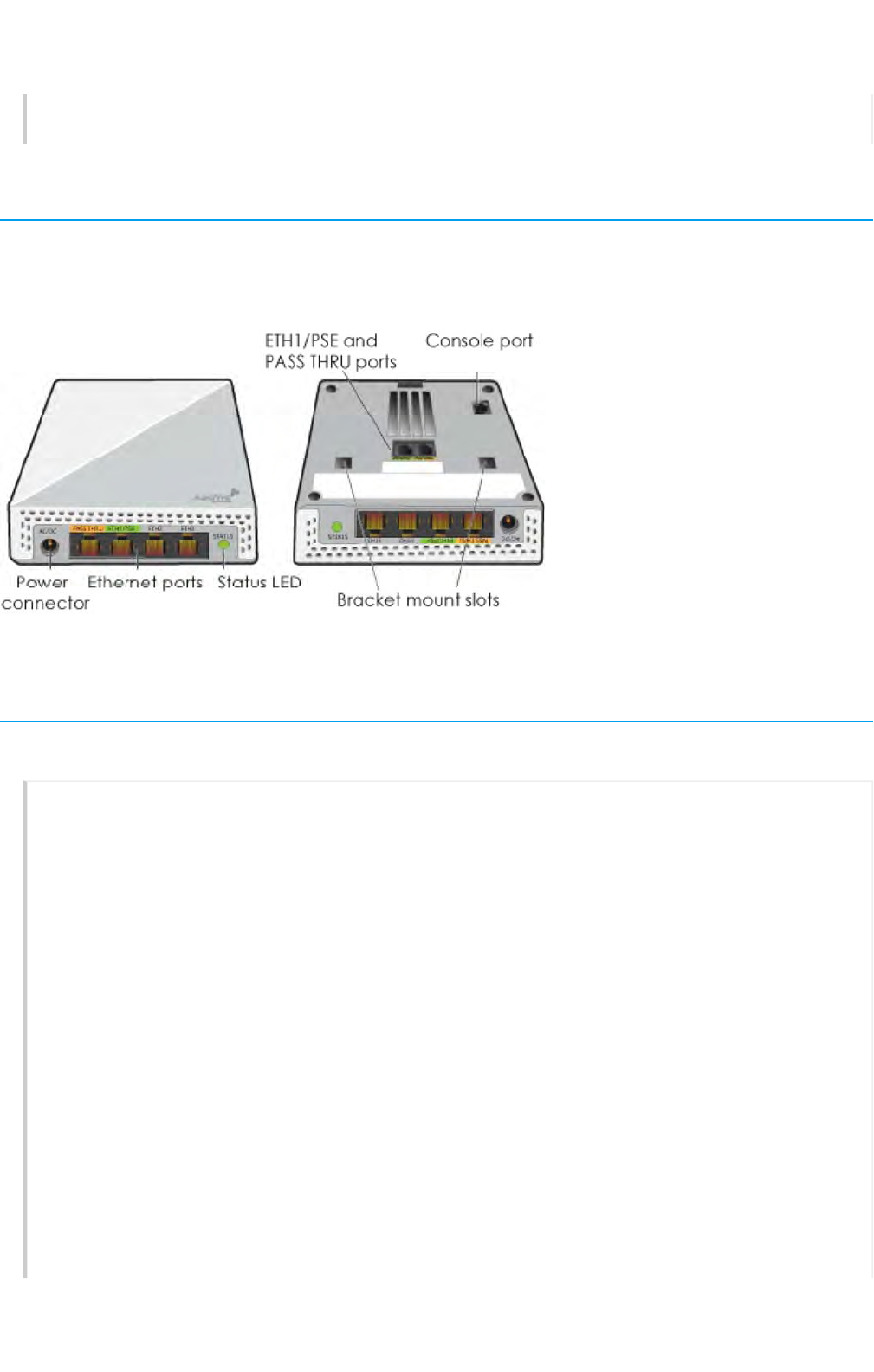
Hardware Components
You can see the hardware components of the AP150W in the illustration below and read about them in
the sections that follow.
Component Descriptions
Status Light
The status light conveys operational states for system power, firmware updates, Ethernet and
wireless interface activity, and major alarms. The AP150W has a device status LED and an Ethernet
port status LED.
The device status LED is on the panel to the right of the Ethernet ports. The colors of this LED
indicate the following states of activity:
Dark: There is no power or the status indicator is disabled.
Amber (flashing): This is an alert that indicates that the device is performing a firmware
upgrade. Do not power off the device during this process.
Amber (steady): This is an alert that indicates that the CAPWAP connection has not been
successfully established, or the device is booting or shutting down.
Green: The device is powered on, a successful CAPWAP connection has been made, and the
firmware is operating normally. During normal operation, the LED produces a slow blink
consisting of 4 seconds of illumination followed by one minute of darkness.
To turn the LEDoff or on, or change the brightness using the CLI, enter:
system led brightness [ bright | soft | dim | off]
Page 9 of 1
7
AP150W Hardware User Guid
e
8
/
21
/
201
7
Preliminarty Draft

You can adjust the brightness level from bright (the default) to soft to dim, or turn it off completely
in HiveManager NG. Navigate to Configure > Network Policy > Additional
Settings>NetworkService > Management Options. Turn Management Options on and scroll
down to the System Settings section. Use the LED brightness drop-down to select the brightness
level that you want.
When you change the brightness setting here, the new setting will apply to all devices
under this network policy. To change the LED brightness for a single device, establish a
console connection and use the CLI command.
For devices running HiveManager Classic, you can set the LEDs for all APs on your network to blink
or remain steady. Navigate to Home> Device Management Settings > LEDMode.
Ethernet Ports
The AP150W has the following RJ45 10/100/1000Base-T/TX Ethernet ports:
• Eth0 / PoE Input: Autosensing 10/100/1000 Base-T Ethernet PoE Input Port
• Eth1 / PoE Output: Autosensing 10/100/1000 Base-T Ethernet PoE Output Port
• Eth2 / Eth3: Autosensing 10/100/1000 Base-T Ethernet Ports
• Two RJ45 passive pass thru ports on the back of the device
•RJ45 Console Port
Power Options
The AP150W can receive 802.3af and 802.3at PoE and PoE+ power through the Eth0 and Eth1
ports. With 802.3af, there is no PoE budget support on the downlink port. With 802.3af the PoE
budget on the downlink port is 12 W.
The AP150W can also be powered using a 48VDC, 0.75 A power supply (sold as an accessory).
Using this method, the PoE budget on the downlink port is 15.4 W.
Antennas
The AP150W has nine internal antennas:
• Five single-band 5 GHz antennas
• Three dual-band 2.4 GHz or 5 GHz antennas
•One
BLE antenna.
Console Port
Through the Console port, you can make a serial connection between your management system
and the AP. The management station from which you connect to the device using the Console
port must have a VT100 emulation program, such as Tera Term Pro© (a free terminal emulator) or
Hilgraeve HyperTerminal® (provided with Windows® operating systems from XP forward). The serial
connection settings are: 9600 bits per second, 8 data bits, no parity, 1 stop bit, no flow control.
Page 10 of 1
7
AP150W Hardware User Guid
e
8
/
21
/
201
7
Preliminarty Draft

The pin-to-signal mapping for the Console port is shown in "Aerohive Device Pin Assignments".
Hardware Specifications
The following specifications describe the physical features and hardware components, PoE electrical
requirements, and the temperature and humidity ranges in which the devices can operate.
Device Specifications
• Chassis dimensions: WxDxH" 4.2" x 1.1" x 6.9" (105.9 mm x 29.2 mm x 175 mm)
• Weight: Device - 0.86 lb (0.39 kg), wall bracket - 0.26 lb (0.1 kg)
• Antennas:
• Two integrated single band 2.4-2.5 GHz omnidirectional antennas
• Three integrated single band 5.1-5.8 GHz omnidirectional antennas
• One BLE internal antenna
•Interfaces:
• Eth0 / POE Input: Autosensing 10/100/1000 Base-‐T Ethernet POE Input Port
• Eth1 / PoE Output: Autosensing 10/100/1000 Base-‐T Ethernet PoE Output Port
• Eth2 / Eth3: 2x Autosensing 10/100/1000 Base-‐T Ethernet Port
• Passive PASS THRU connection : Two RJ45 ports (from the back of the AP to the
bottom)
• Built-in BLE and Zigbee (future use)
•RJ45 Console Port
• AC power input connector (48 VDC, 0.75 A power supply sold separately)
Power Specifications
• IEEE 802.3af PoE input: Typical 11.3 W, maximum 12.4 W
• IEEE 802.3at PoE input: Typical 23.6 W, maximum 24.9 W
• 802.3af PoE-capable Gigabit Ethernet port
• PoE nominal input voltages: 48
Environmental Specifications
• Operating temperature: 32° to 104° F (0° to 40° C)
• Storage temperature: -40° to 158° F (-40° to 70° C)
• Relative Humidity: 5 to 95% RH (noncondensing)
Regulatory Compliance Statements
The regulatory compliance statements in this section apply to AP150W devices.
For Japan, the AP150W is restricted for indoor use in the 5150-5350 MHz band only.
Page 11 of 1
7
AP150W Hardware User Guid
e
8
/
21
/
201
7
Preliminarty Draft

Compliance Statements
The following compliance information applies to AP150W devices.
R&TTE and Low Voltage Directives
This device is compliant with the following directives:
• R&TTEDirective 1995/5/EC
• Low Voltage Directive 72/23/EEC
AP250 Compliance Statement - Europe
THE EUROPEAN COMMISSION, Having regard to the Treaty on the Functioning of the European
Union,
Having regard to Directive 2014/53/EU of the European Parliament and of the Council of 16 April
2014 on the harmonisation of the laws of the Member States relating to the making available on
the market of radio equipment and repealing Directive 1999/5/EC1, and in particular Articles 10
(10) and 45(2), thereof
Whereas:
(1) Article 10(10) of Directive 2014/53/EU provides that in cases of restrictions on putting into
service or of requirements for authorisation of use, information available on the packaging
shall allow the identification of the Member States or the geographical area within a Member
State where restrictions on putting into service or requirements for authorisation of use exist
and that such information shall be completed in the instructions accompanying the radio
equipment.
(2) Pursuant to Article 10(10) of Directive 2014/53/EU the Commission may adopt implementing
acts specifying how to present the information provided for in Article 10(10).
(3) Those implementing acts shall be adopted in accordance with the advisory procedure
referred to in Article 45(2) of Directive 2014/53/EU.
(4) The measures set out in this Regulation are in accordance with the opinion of the
Telecommunication Conformity Assessment and Market Surveillance Committee, established
in accordance with Article 45 of Directive 2014/53/EU.
HAS ADOPTED THIS REGULATION:
Article 1
This Regulation specifies how to present the information provided for in Article 10(10) of Directive
2014/53/EU and shall apply only to radio equipment which is subject to restrictions on putting into
service or to requirements for authorisation of use in at least one Member State.
Article 2
1. If radio equipment is subject to restrictions on putting into service or to requirements for
authorisation of use, as provided for in Article 10(10) of Directive 2014/53/EU, the packaging of
the radio equipment shall indicate visibly and legibly:
(a) a pictogram, as set out in Annex I; or
Page 1
2
of 1
7
AP150W Hardware User Guid
e
8
/
21
/
201
7
Preliminarty Draft

(b) the words 'Restrictions or Requirements in', in a language easily understood by end-
users as determined by the Member State concerned, followed by the abbreviations of
the Member States, as prescribed in Annex II, where such restrictions or requirements exist.
2. If radio equipment is subject to restrictions on putting into service or to requirements for
authorisation of use, as provided for in Article 10(10) of Directive 2014/53/EU, the instructions
accompanying the radio equipment shall indicate, in a language easily understood by end-
users as determined by the Member State concerned, the list of the Member States and
geographical areas within the Member States where such restrictions or requirements exist, as
well as the types of restrictions or requirements applicable in each Member State and each
geographical area within a Member State.
Article 3
This Regulation shall enter into force on the twentieth day following that of its publication in the
Official Journal of the European Union, and it shall apply as of …..[6 months after its entry into
force]
Radio equipment, which is placed on the market after [date: one day before the entry into force
of this Regulation] and is in conformity with this Regulation, shall be deemed to be in conformity
with Article 10(10) of Directive 2014/53/EU.
This Regulation shall be binding in its entirety and directly applicable in all Member States. Done at
Brussels,
For the Commission The President
Jean-Claude Juncker
EU Declaration of Conformity
This device complies with the essential requirements of the R&TTE Directive 1999/5/EC. The
following test methods have been applied in order to prove presumption of conformity with the
essential requirements of the R&TTE Directive 1999/5/EC:
EN 60950-1:2009 2006+A2:2013
Safety of Information Technology Equipment
EN 62311: 2008 / Article 3(1)(a) and Article 2 2006/95/EC)
Assessment of electronic and electrical equipment related to human exposure restrictions for
electromagnetic fields (0 Hz-300 GHz)
EN 300 328 V1.9.1: 2015-02
Electromagnetic compatibility and Radio spectrum Matters (ERM); Wideband transmission
systems; Data transmission equipment operating using wide band modulation techniques;
Harmonized EN covering the essential requirements of article 3.2 of the R&TTE Directive
EN 301 893 V1.8.1: 2015-03
Broadband Radio Access Networks (BRAN); 5 GHz high performance RLAN; Harmonized EN
covering the essential requirements of article 3.2 of the R&TTE Directive
EN 301 489-1 V1.9.2: 2011
Page 1
3
of 1
7
AP150W Hardware User Guid
e
8
/
21
/
201
7
Preliminarty Draft

Electromagnetic compatibility and Radio spectrum Matters (ERM); Electromagnetic Compatibility
(EMC) standard for radio equipment and services; Part 1: Common technical requirements
EN 301 489-17 V2.2.1 2012
Electromagnetic compatibility and Radio spectrum Matters (ERM); Electromagnetic Compatibility
(EMC) standard for radio equipment; Part 17: Specific conditions for Broadband Data Transmission
Systems
In Italy the end-user should apply for a license at the national spectrum authorities in order to
obtain authorization to use the device for setting up outdoor radio links and/or for supplying
public access to telecommunications and/or network services.
•Česky [Czech]: [Aerohive] tímto prohlašuje, že tento [AP150W] je ve shodě se základními
požadavky a dalšími příslušnými ustanoveními směrnice 1999/5/ES.
•Dansk [Danish]: Undertegnede [Aerohive] erklærer herved, at følgende udstyr [AP150W]
overholder de væsentlige krav og øvrige relevante krav i direktiv 1999/5/EF.
•Deutsch [German]: Hiermit erklärt [Aerohive], dass sich das Gerät [AP150W] in
Übereinstimmung mit den grundlegenden Anforderungen und den übrigen einschlägigen
Bestimmungen der Richtlinie 1999/5/EG befindet.
•Eesti [Estonian]: Käesolevaga kinnitab [Aerohive] seadme [AP150W] vastavust direktiivi
1999/5/EÜ põhinõuetele ja nimetatud direktiivist tulenevatele teistele asjakohastele sätetele.
•English: Hereby, [Aerohive], declares that this [AP150W] is in compliance with the essential
requirements and other relevant provisions of Directive 1999/5/EC.
•Español [Spanish]: Por medio de la presente [Aerohive] declara que el [AP150W] cumple
con los requisitos esenciales y cualesquiera otras disposiciones aplicables o exigibles de la
Directiva 1999/5/CE.
•Ελληνική [Greek]: ΜΕ ΤΗΝ ΠΑΡΟΥΣΑ [Aerohive] ΔΗΛΩΝΕΙ ΟΤΙ [AP150W] ΣΥΜΜΟΡΦΩΝΕΤΑΙ
ΠΡΟΣ ΤΙΣ ΟΥΣΙΩΔΕΙΣ ΑΠΑΙΤΗΣΕΙΣ ΚΑΙ ΤΙΣ ΛΟΙΠΕΣ ΣΧΕΤΙΚΕΣ ΔΙΑΤΑΞΕΙΣ ΤΗΣ ΟΔΗΓΙΑΣ 1999/5/ΕΚ.
•Français [French]: Par la présente [Aerohive] déclare que l'appareil [AP150W] est conforme
aux exigences essentielles et aux autres dispositions pertinentes de la directive 1999/5/CE.
•Italiano [Italian]: Con la presente [Aerohive] dichiara che questo [AP150W] è conforme ai
requisiti essenziali ed alle altre disposizioni pertinenti stabilite dalla direttiva 1999/5/CE.
•Latviski [Latvian]: Ar šo [Aerohive] deklarē, ka [AP150W] atbilst Direktīvas 1999/5/EK
būtiskajām prasībām un citiem ar to saistītajiem noteikumiem.
•Lietuvių [Lithuanian]: Šiuo [Aerohive] deklaruoja, kad šis [AP150W] atitinka esminius
reikalavimus ir kitas 1999/5/EB Direktyvos nuostatas.
•Nederlands [Dutch]: Hierbij verklaart [Aerohive] dat het toestel [AP150W] in
overeenstemming is met de essentiële eisen en de andere relevante bepalingen van richtlijn
1999/5/EG.
•Malti [Maltese]: Hawnhekk, [Aerohive], jiddikjara li dan [AP150W] jikkonforma mal-ħtiġijiet
essenzjali u ma provvedimenti oħrajn relevanti li hemm fid-Dirrettiva 1999/5/EC.
•Magyar [Hungarian]: Alulírott, [Aerohive] nyilatkozom, hogy a [AP150W] megfelel a
vonatkozó alapvetõ követelményeknek és az 1999/5/EC irányelv egyéb elõírásainak.
•Polski [Polish]: Niniejszym [Aerohive] oświadcza, że [AP150W] jest zgodny z zasadniczymi
wymogami oraz pozostałymi stosownymi postanowieniami Dyrektywy 1999/5/EC.
•Português [Portuguese]: [Aerohive] declara que este [AP150W] está conforme com os
requisitos essenciais e outras disposições da Directiva 1999/5/CE.
Page 1
4
of 1
7
AP150W Hardware User Guid
e
8
/
21
/
201
7
Preliminarty Draft

•Slovensko [Slovenian
]
: [Aerohive] izjavlja, da je ta [AP150W] v skladu z bistvenimi zahtevami
in ostalimi relevantnimi določili direktive 1999/5/ES.
•Slovensky [Slovak]: [Aerohive] týmto vyhlasuje, že [AP150W] spĺňa základné požiadavky a
všetky príslušné ustanovenia Smernice 1999/5/ES.
•Suomi [Finnish]: [Aerohive] vakuuttaa täten että [AP150W] tyyppinen laite on direktiivin
1999/5/EY oleellisten vaatimusten ja sitä koskevien direktiivin muiden ehtojen mukainen.
EURadiation Warning Statement
To meet radiation exposure requirements, these devices should be installed at a minimum
distance of 8" (20 cm) from people or animals.
Federal Communication Commission Interference Statement
This equipment has been tested and found to comply with the limits for a Class B digital device,
pursuant to Part 15 of the FCC Rules. These limits are designed to provide reasonable protection
against harmful interference in a residential installation. This equipment generates, uses and can
radiate radio frequency energy and, if not installed and used in accordance with the instructions,
may cause harmful interference to radio communications. However, there is no guarantee that
interference will not occur in a particular installation. If this equipment does cause harmful
interference to radio or television reception, which can be determined by turning the equipment
off and on, the user is encouraged to try to correct the interference by one of the following
measures:
• Reorient or relocate the receiving antenna.
• Increase the separation between the equipment and receiver.
• Connect the equipment into an outlet on a circuit different from that to which the receiver is
connected.
• Consult the dealer or an experienced radio or TV technician for help.
FCC Caution: Any changes or modifications not expressly approved by the party responsible for
compliance could void the user's authority to operate this equipment.
This device complies with Part 15 of the FCC Rules. Operation is subject to the following two
conditions: (1) This device may not cause harmful interference, and (2) this device must accept
any interference received, including interference that may cause undesired operation.
IMPORTANT NOTE:
Radiation Exposure Statement:
This equipment complies with FCC radiation exposure limits set forth for an uncontrolled
environment. This equipment should be installed and operated with minimum distance 8" (20 cm)
between the radiator and people or animals.
This transmitter must not be co-located or operating in conjunction with any other antenna or
transmitter.
Country Code selection feature to be disabled for products marketed to the US/CANADA.
For products available in the US/CANADA, only channels 1 through 11 can be operated. Selection
of other channels is not possible.
This device is for indoor use only.
Page 1
5
of 1
7
AP150W Hardware User Guid
e
8
/
21
/
201
7
Preliminarty Draft

Industry Canada Statement:
This device complies with Industry Canada license-exempt RSS standard(s). Operation is subject to
the following two conditions:
• This device may not cause interference, and
• This device must accept any interference, including interference that may cause undesired
operation of the device.
Le présent appareil est conforme aux CNR d'Industrie Canada applicables aux appareils radio
exempts de licence. L'exploitation est autorisée aux deux conditions suivantes :
• l'appareil ne doit pas produire de brouillage, et
• l'utilisateur de l'appareil doit accepter tout brouillage radioélectrique subi, même si le
brouillage est susceptible d'en compromettre le fonctionnement.
Caution:
(i) the device for operation in the band 5150-5250 MHz is only for indoor use to reduce the
potential for harmful interference to co-channel mobile satellite systems;
Avertissement:
(i) les dispositifs fonctionnant dans la bande 5150-5250 MHz sont réservés uniquement pour une
utilisation à l’intérieur afin de réduire les risques de brouillage préjudiciable aux systèmes de
satellites mobiles utilisant les mêmes canaux;
Radiation Exposure Statement:
This equipment complies with IC radiation exposure limits set forth for an uncontrolled
environment. This equipment should be installed and operated with minimum distance 20 cm
between the radiator and people or animals.
Déclaration d'exposition aux radiations:
Cet équipement est conforme aux limites d'exposition aux rayonnements IC établies pour un
environnement non contrôlé. Cet équipement doit être installé et utilisé avec un minimum de 20
cm de distance entre la source de rayonnement et votre corps.
For products available in the US/CANADA, only channels 1 through 11 can be operated. Selection
of other channels is not possible.
Pour les produits disponibles aux États-Unis / Canada du marché, seul le canal 1 à 11 peuvent être
exploités. Sélection d'autres canaux n'est pas possible.
For indoor use only.
Pour une utilisation en intérieur uniquement.
Taiwan Compliance Information
AerohiveAP150W
Page 1
6
of 1
7
AP150W Hardware User Guid
e
8
/
21
/
201
7
Preliminarty Draft

第十二
條
→經型式認證合格之低功率射頻電機,非經許可,公司,商號或使用者均不得擅自變更頻率、加
大
功率或變更原設計之特性及功能。
第十四條→低功率射頻電機之使用不得影響飛航安全及干擾合法通信;經發現有干擾現象時,應立即停用,
並改善至無干擾時方得繼續使用。
前項合法通信,指依電信法規定作業之無線電通信。 低功率射頻電機須忍受合法通信或工業、科學及醫療用
電波輻射性電機設備之干擾。
在 5.25-5.35 秭赫頻帶內操作之無線資訊傳輸設備,限於室內使用。
無線資訊傳設備的製造廠商應確保頻率穩定性,如依製造廠商使用手冊上所述正常操作,發射的信號應維持
於操作頻帶中。
Taiwan MPE Warning
電磁波曝露量MPE標準值1 mW/cm2,送測產品實值為0.75289 mW/cm2,本產品使用時建議應距離人體
20cm。
Aerohive Documentation Portal |Aerohive Blogs |HiveCare Community Forum
Copyright © 2017Aerohive Networks, Inc.
Page 1
7
of 1
7
AP150W Hardware User Guid
e
8
/
21
/
201
7
file:///C:/Users/dknodel/AppData/Local/Temp/MC_.ht
m
Preliminarty Draft