Aerohive Networks AP230 Access Point User Manual Aerohive AP230 User Guide
Aerohive Networks, Inc. Access Point Aerohive AP230 User Guide
UserManual.wiki
>
Aerohive Networks
>
AP230 User Manual
>
User manual-1
Contents
1.
User manual (statement)
2.
User manual-1
3.
User manual-2
User manual-1
Navigation menu
Upload a User Manual
Namespaces
Wiki Guide
HTML
PDF
Info
Views
User Manual
Discussion / Help
Navigation


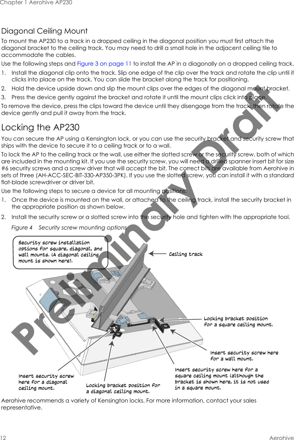
![Chapter 1 Aerohive AP23014 Aerohive• EN 300 328 V1.8.1: 2012-06• Electromagnetic compatibility and Radio spectrum Matters (ERM); Wideband transmission systems; Data transmission equipment operating using wide band modulation techniques; Harmonized EN covering the essential requirements of article 3.2 of the R&TTE Directive• EN 301 893 V1.7.1: 2012-06• Broadband Radio Access Networks (BRAN); 5 GHz high performance RLAN; Harmonized EN covering the essential requirements of article 3.2 of the R&TTE Directive• EN 301 489-1 V1.9.2: 2011• Electromagnetic compatibility and Radio spectrum Matters (ERM); Electromagnetic Compatibility (EMC) standard for radio equipment and services; Part 1: Common technical requirements• EN 301 489-17 V2.2.1 2012•Electromagnetic compatibility and Radio spectrum Matters (ERM); Electromagnetic Compatibility (EMC) standard for radio equipment; Part 17: Specific conditions for Broadband Data Transmission SystemsIn Italy the end-user should apply for a license at the national spectrum authorities in order to obtain authorization to use the device for setting up outdoor radio links and/or for supplying public access to telecommunications and/or network services.Česky [Czech][Aerohive] tímto prohlašuje, že tento [AP230] je ve shodě se základními požadavky a dalšími příslušnými ustanoveními směrnice 1999/5/ES.Dansk [Danish]Undertegnede [Aerohive] erklærer herved, at følgende udstyr [AP230] overholder de væsentlige krav og øvrige relevante krav i direktiv 1999/5/EF.Deutsch [German]Hiermit erklärt [Aerohive], dass sich das Gerät [AP230] in Übereinstimmung mit den grundlegenden Anforderungen und den übrigen einschlägigen Bestimmungen der Richtlinie 1999/5/EG befindet.Eesti [Estonian]Käesolevaga kinnitab [Aerohive] seadme [AP230] vastavust direktiivi 1999/5/EÜ põhinõuetele ja nimetatud direktiivist tulenevatele teistele asjakohastele sätetele.EnglishHereby, [Aerohive], declares that this [AP230] is in compliance with the essential requirements and other relevant provisions of Directive 1999/5/EC.Español [Spanish]Por medio de la presente [Aerohive] declara que el [AP230] cumple con los requisitos esenciales y cualesquiera otras disposiciones aplicables o exigibles de la Directiva 1999/5/CE.Preliminary Draft](https://usermanual.wiki/Aerohive-Networks/AP230.User-manual-1/User-Guide-2217823-Page-18.png)
![AP230 User Guide 15AP230 PRODUCT OVERVIEWFederal Communication Commission Interference StatementThis equipment has been tested and found to comply with the limits for a Class B digital device, pursuant to Part 15 of the FCC Rules. These limits are designed to provide reasonable protection against harmful interference in a residential installation. This equipment generates, uses and can radiate radio frequency energy and, if not installed and used in accordance with the instructions, may cause harmful interference to radio communications. However, there is no guarantee that interference will not occur in a particular installation. If this equipment does cause harmful interference to radio or television reception, which can be determined by turning the equipment off and on, the user is encouraged to try to correct the interference by one of the following measures:Ελληνική [Greek]ΜΕ ΤΗΝ ΠΑΡΟΥΣΑ [Aerohive] ΔΗΛΩΝΕΙ ΟΤΙ [AP230] ΣΥΜΜΟΡΦΩΝΕΤΑΙ ΠΡΟΣ ΤΙΣ ΟΥΣΙΩΔΕΙΣ ΑΠΑΙΤΗΣΕΙΣ ΚΑΙ ΤΙΣ ΛΟΙΠΕΣ ΣΧΕΤΙΚΕΣ ΔΙΑΤΑΞΕΙΣ ΤΗΣ ΟΔΗΓΙΑΣ 1999/5/ΕΚ.Français [French]Par la présente [Aerohive] déclare que l'appareil [AP230] est conforme aux exigences essentielles et aux autres dispositions pertinentes de la directive 1999/5/CE.Italiano [Italian]Con la presente [Aerohive] dichiara che questo [AP230] è conforme ai requisiti essenziali ed alle altre disposizioni pertinenti stabilite dalla direttiva 1999/5/CE.Latviski [Latvian] Ar šo [Aerohive] deklarē, ka [AP230] atbilst Direktīvas 1999/5/EK būtiskajām prasībām un citiem ar to saistītajiem noteikumiem.Lietuvių [Lithuanian] Šiuo [Aerohive] deklaruoja, kad šis [AP230] atitinka esminius reikalavimus ir kitas 1999/5/EB Direktyvos nuostatas.Nederlands [Dutch]Hierbij verklaart [Aerohive] dat het toestel [AP230] in overeenstemming is met de essentiële eisen en de andere relevante bepalingen van richtlijn 1999/5/EG.Malti [Maltese]Hawnhekk, [Aerohive], jiddikjara li dan [AP230] jikkonforma mal-ħtiġijiet essenzjali u ma provvedimenti oħrajn relevanti li hemm fid-Dirrettiva 1999/5/EC.Magyar [Hungarian]Alulírott, [Aerohive] nyilatkozom, hogy a [AP230] megfelel a vonatkozó alapvetõ követelményeknek és az 1999/5/EC irányelv egyéb elõírásainak.Polski [Polish]Niniejszym [Aerohive] oświadcza, że [AP230] jest zgodny z zasadniczymi wymogami oraz pozostałymi stosownymi postanowieniami Dyrektywy 1999/5/EC.Português [Portuguese][Aerohive] declara que este [AP230] está conforme com os requisitos essenciais e outras disposições da Directiva 1999/5/CE.Slovensko [Slovenian][Aerohive] izjavlja, da je ta [AP230] v skladu z bistvenimi zahtevami in ostalimi relevantnimi določili direktive 1999/5/ES.Slovensky [Slovak [Aerohive] týmto vyhlasuje, že [AP230] spĺňa základné požiadavky a všetky príslušné ustanovenia Smernice 1999/5/ES.Suomi [Finnish][Aerohive] vakuuttaa täten että [tAP230] tyyppinen laite on direktiivin 1999/5/EY oleellisten vaatimusten ja sitä koskevien direktiivin muiden ehtojen mukainen.Preliminary Draft](https://usermanual.wiki/Aerohive-Networks/AP230.User-manual-1/User-Guide-2217823-Page-19.png)