Aerohive Networks HIVEAP340 802.11 a/b/g/n access point User Manual Aerohive Deployment Guide
Aerohive Networks, Inc. 802.11 a/b/g/n access point Aerohive Deployment Guide
UserManual.wiki
>
Aerohive Networks
>
HIVEAP340 User Manual
>
Users Manual 4
Contents
1.
Users Manual 1
2.
Users Manual 2
3.
Users Manual 3
4.
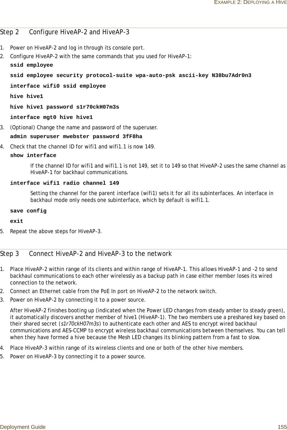
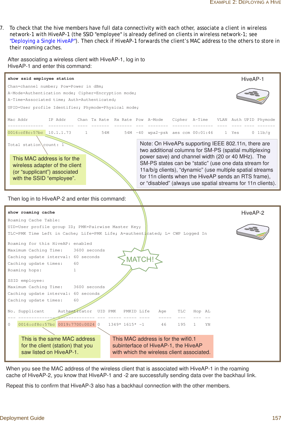
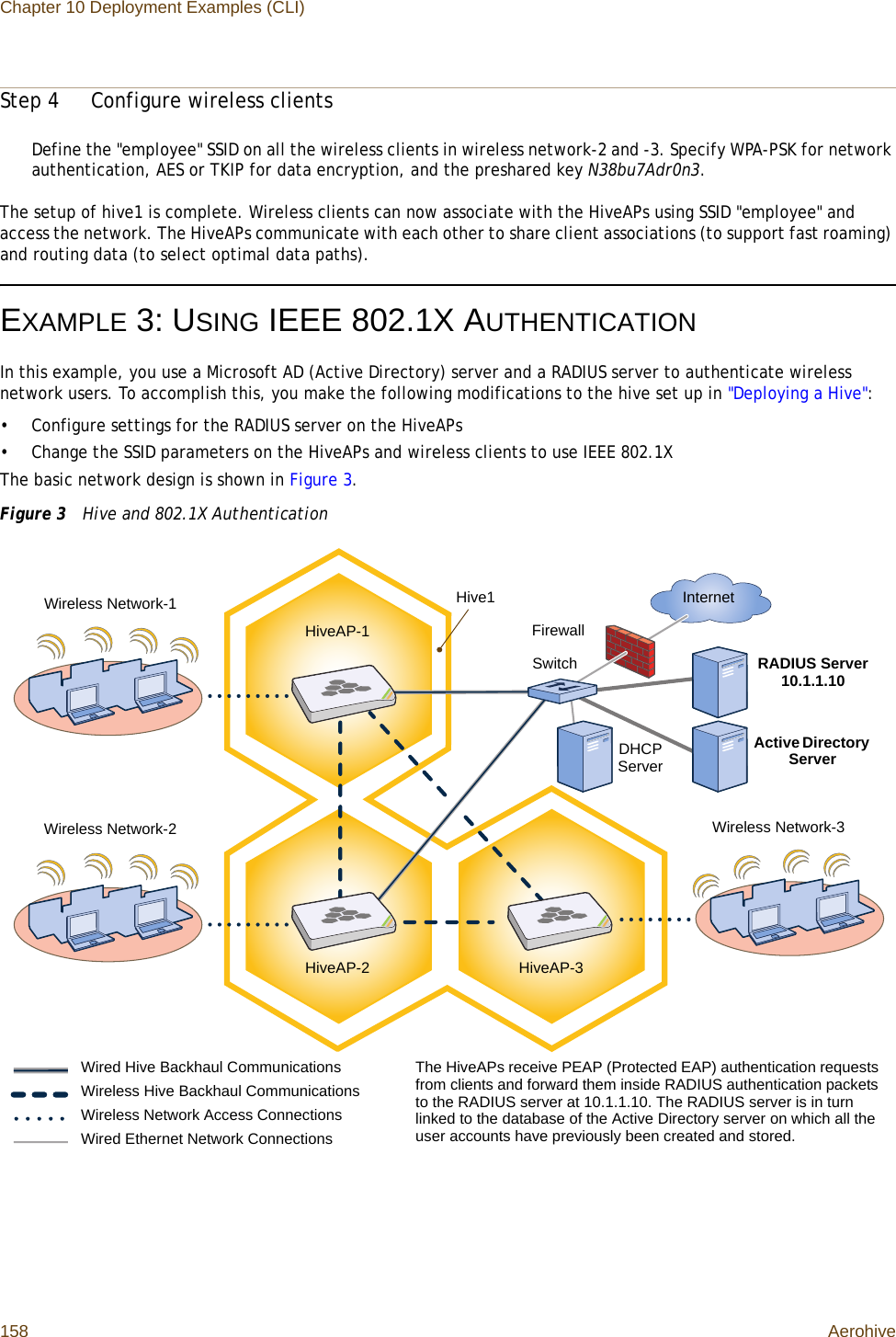
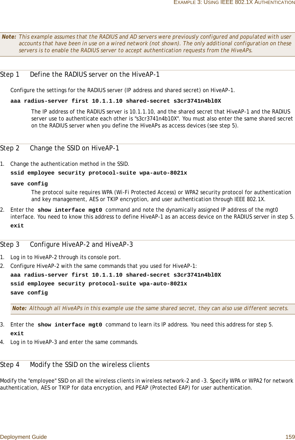
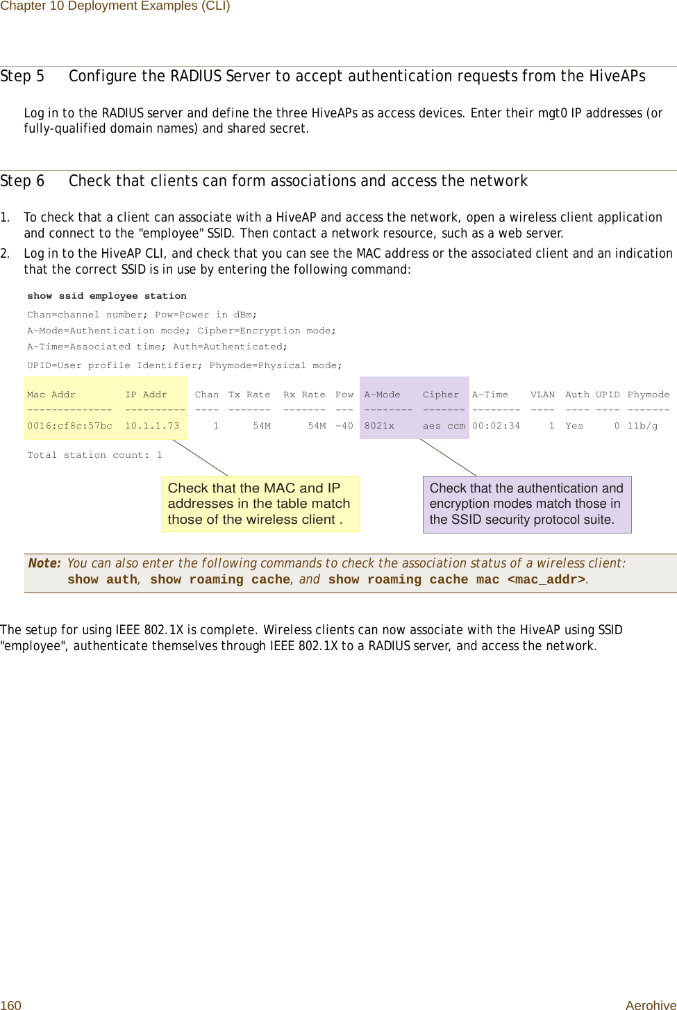
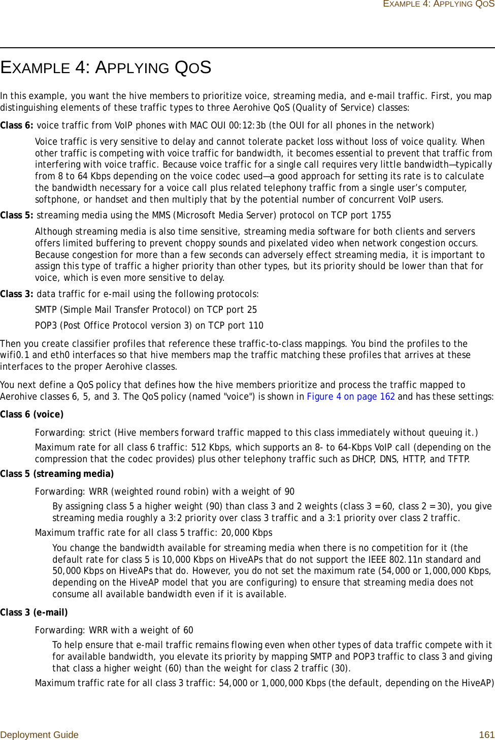
Users Manual 4
5.
Users Manaul 1
6.
Users Manaul 2
Users Manual 4
Navigation menu
Upload a User Manual
Namespaces
Wiki Guide
HTML
PDF
Info
Views
User Manual
Discussion / Help
Navigation