Aerohive Networks HIVEAP340 802.11 a/b/g/n access point User Manual Aerohive Deployment Guide
Aerohive Networks, Inc. 802.11 a/b/g/n access point Aerohive Deployment Guide
Contents
Users Manual 4
Chapter 8 HiveManager Configuration Examples
90 Aerohive
This chapter contains a sequential flow of examples that show how to import and organize maps, install HiveAPs on
the network and link them to maps, configure typically needed features, assign these features to HiveAPs, and push
configurations to the HiveAPs across the network. The examples are as follows:
•"Example 1: Mapping Locations and Installing HiveAPs" on page 91
Upload image files of topology maps to HiveManager and use one of two ways to associate physical HiveAPs
with their corresponding icons on the maps.
•"Example 2: Defining Network Objects and MAC Filters" on page 97
Define a MAC OUI (organizationally unique identifier), VLANs, and IP addresses for use by other
configuration objects. Define a MAC filter so that QoS classifiers and SSID profiles can reference them. Map
the MAC OUI and several services to Aerohive classes.
•"Example 3: Providing Guest Access" on page 104
Provide controlled and limited network access for guests. Two approaches are presented.
•"Example 4: Creating User Profiles" on page 113
Define several user profiles, their companion QoS forwarding rates and priorities, and their VLANs.
•"Example 5: Setting SSIDs" on page 117
Define sets of authentication and encryption services that wireless clients and HiveAPs use when
communicating with each other.
•"Example 6: Setting Management Service Parameters" on page 120
Configure DNS, syslog, SNMP, and NTP settings for HiveAPs.
•"Example 7: Defining AAA RADIUS Settings" on page 123
Define AAA RADIUS server settings to use when HiveAPs send 802.1X authentication requests.
•"Example 8: Creating Hives" on page 125
Create hives so that sets of HiveAPs can exchange information with each other over the network to
coordinate client access, provide best-path forwarding, and enforce QoS policies.
•"Example 9: Creating WLAN Policies" on page 126
Define WLAN policies. These are sets of configuration objects (defined in previous examples) that HiveAPs
use to control how wireless clients access the network.
•"Example 10: Assigning Configurations to HiveAPs" on page 135
Assign WLAN policies, radio profiles, and maps to detected HiveAPs so that you can begin managing them
through HiveManager. Also change HiveAP login settings and country codes.
Deployment Guide 91
EXAMPLE 1: MAPPING LOCATIONS AND INSTALLING HIVEAPS
EXAMPLE 1: MAPPING LOCATIONS AND INSTALLING HIVEAPS
HiveManager allows you to mark the location of HiveAPs on maps so that you can track devices and monitor their
status. First, you must upload the maps to HiveManager, and then name and arrange them in a structured hierarchy
(see "Setting Up Topology Maps"). After that, you can follow one of two ways to install HiveAPs so that you can later
put their corresponding icons on the right maps (see "Preparing the HiveAPs" on page 94).
Setting Up Topology Maps
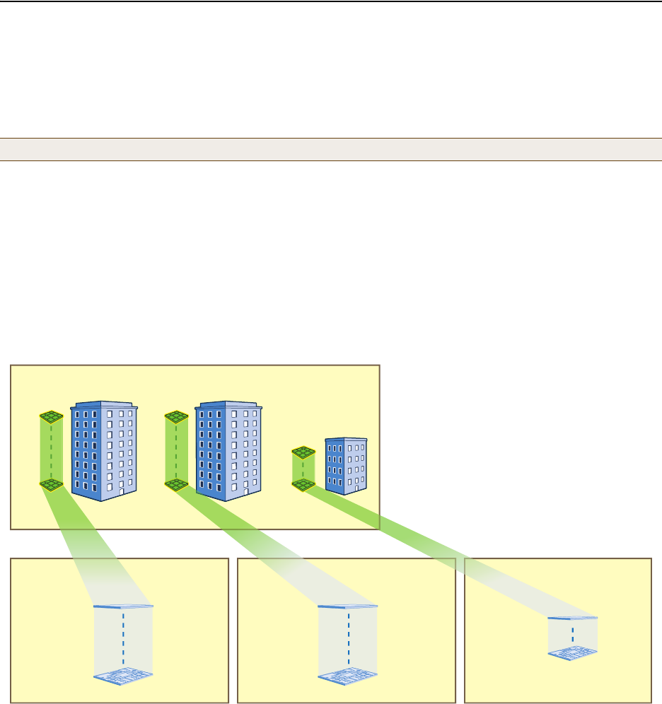
In this example, you upload maps to HiveManager showing floor plans for three office buildings and organize them in
a hierarchical structure. You need to make .png of .jpg files of drawings or blueprints showing the layout of each
floor. Also, as an easy means of organizing the maps in the HiveManager GUI, you create a file showing the three
buildings HQ-B1, HQ-B2, and Branch-1. By using this drawing at the top topographical level, you can display icons for
each floor of each building. You can then click an icon to link to its corresponding map. This is shown in Figure 2.
Figure 2 Organizational Structure of Level-1 and -2 Maps
Uploading Maps
1. Log in to the HiveManager GUI as explained in " Installing and Connecting to the HiveManager GUI" on page 79.
2. Click To pol ogy, right-click World, and then choose Add/Delete Image from the pop-up menu that appears.
3. In the Add/Delete Image window, click Browse, navigate to the directory containing the image files that you
want to upload, and select one of them.
4. Click Upload.
Note: All image files that you upload to HiveManager must be in .png or .jpg format.
8 Maps
(one per floor)
“HQ-B1-F1”
“HQ-B1-F8”
8 Maps
“HQ-B2-F1”
“HQ-B2-F8”
4 Maps
“Branch-1-F1”
“Branch-1-F4”
Headquarters Building 1 (HQ-B1) Maps Headquarters Building 2 (HQ-B2) Maps Branch-1 Maps
CorpOffices (Level-1 Map)
This map shows 3 buildings and 20 icons that link to level-2 maps.
8 icons linking
to level-2 maps 8 icons linking
to level-2 maps 4 icons linking
to level-2 maps
Level 1
Level 2
Double-clicking a floor icon on the CorpOffices map
(level 1) opens the corresponding level-2 map.
You can also navigate to any map within the
Topology Maps section of the navigation tree in the
HiveManager GUI.
Chapter 8 HiveManager Configuration Examples
92 Aerohive
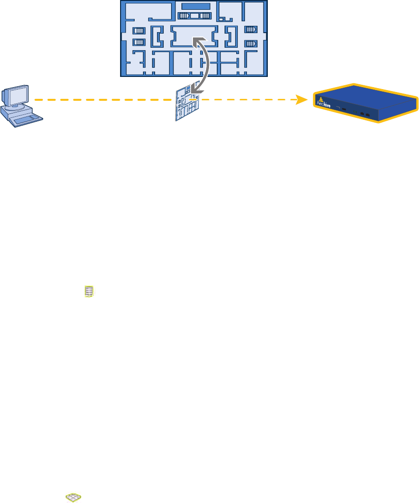
The selected image file is transferred from your management system to HiveManager as shown in Figure 3.
Figure 3 Uploading a Map of a Building Floor Plan
5. Repeat this for all the image files that you need to load. In this example, you load 21 files:
• 8 maps for the eight floors in HQ-B1 (Headquarters Building 1)
• 8 maps for the eight floors in HQ-B2 (Headquarters Building 2)
• 4 maps for the four floors in Branch-1
• 1 file (named "corp_offices.png" in this example) that shows a picture of the three buildings
Naming and Arranging Maps within a Structure
1. Click Topology, right-click the top level map "World", and then choose Edit from the pop-up menu that appears.
2. In the Edit Map - World dialog box, enter the following, and then click Update:
•Map Name: CorpOffices (Note that spaces are not allowed in map level names.)
•Map Icon: Building
• Background Image: Choose corp_offices.png from the drop-down list.
• Environment: Because the CorpOffices "map" does not contain any HiveAP icons—it is an illustration of three
buildings that you use to organize the submaps of the floors in each building—the environment setting is
irrelevant. Leave it at its default, Free Space.
• Width (optional): Because the corp_offices.png depicts buildings instead of a floor plan, it is not necessary
to specify the width of the image.
3. Click Topology, right-click the top level map "CorpOffices", and then choose New from the pop-up menu that
appears.
4. In the New Map (Submap for CorpOffices) dialog box, enter the following, and then click Create:
•Map Name: HQ-B1-F
•Map Icon: Floor
• Background Image: Choose HQ-B1-F1.png from the drop-down list.
• Environment: Because the environment is that of a typical office building, choose Enterprise. The
environment assists in the prediction of signal strength and attenuation shown in the heat maps.
•Width: 80 feet (HiveManager automatically calculates the height based on the aspect ratio of the image.)
A white floor icon ( ) labeled "HQ-B1-F1" appears on the CorpOffices image, and a new entry named
"HQ-B1-F1" appears nested under "CorpOffices" in the navigation tree.
5. Click Unlock, select the icon, drag it to the location you want, and then click Save.
6. Click Topology, right-click the top level map "CorpOffices", and then choose New from the pop-up menu that
appears.
Management System HiveManager
Map showing one
of the floor plans
Uploading map to HiveManager
Deployment Guide 93
EXAMPLE 1: MAPPING LOCATIONS AND INSTALLING HIVEAPS
7. In the New Map (Submap for CorpOffices) dialog box, enter the following, and then click Create:
•Map Name: HQ-B1-F2
•Map Icon: Floor
• Background Image: Choose HQ-B1-F2.png from the drop-down list.
• Environment: Enterprise
•Width: 80 feet
A white floor icon labeled "HQ-B1-F2" appears on the CorpOffices image, and a new entry named "HQ-B1-F2"
appears nested under "CorpOffices" in the navigation tree.
8. Click Unlock, select the icon, drag it to the location you want, and then click Save.
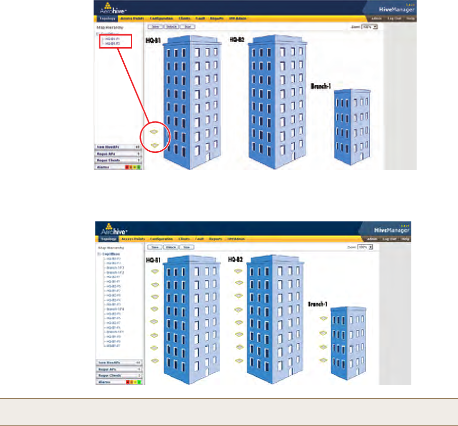
After adding the CorpOffices "map" (really an illustration showing three buildings), two floor plans for the first
and second floors of "HQ-B1", and dragging the floor icons into position, the display of the CorpOffices map
looks similar to that in Figure 4.
Figure 4 CorpOffice Map (Level 1) with Links to Level-2 Maps HQ-B1-F1 and HQ-B1-F2
9. Repeat this process until you have arranged all the maps and icons in place as shown in Figure 5.
Figure 5 CorpOffice Map with Links to All Level-2 Maps
Note: You can add as many levels as necessary to the map hierarchy. You can also delete maps as long as they
do not have any submaps or HiveAP icons on them.
The submaps in the
navigation tree and the
icons on this map link
to other maps.
Click a submap or
double-click an icon to
open the map to which
it links.

Chapter 8 HiveManager Configuration Examples
94 Aerohive
Preparing the HiveAPs
There are several approaches that you can take when mapping the location of installed HiveAP devices. Two
possible approaches are presented below. With the first approach ("Using SNMP"), HiveManager automatically assigns
HiveAPs to maps. This approach does require a small amount of configuration of each HiveAP up front, but after the
HiveAPs form a CAPWAP connection with HiveManager, the automatic assignment of HiveAPs to their appropriate
maps on HiveManager occurs without any further effort. The second approach ("Using MAC Addresses" on page 95)
allows you to install HiveAPs without needing to do any extra configurations, but you later have to match each
HiveAP with the right map in HiveManager manually.
Using SNMP
This approach makes use of the SNMP (Simple Network Management Protocol) sysLocation MIB (Management
Information Base) object, which you define on HiveAPs. HiveManager can use this information to associate a HiveAP
with a map and provide a description of where on the map each HiveAP belongs.
1. Make copies of the maps you uploaded to HiveManager, label them, and take them with you for reference when
installing the HiveAPs.
2. For each HiveAP that you install, do the following:
1. Make a serial connection to the console port, and log in (see "Log in through the console port" on page 150).
2. Enter the following command, in which string1 describes the location of the HiveAP on the map (in open
format) and string2 is the name of the map:
snmp location string1@string2
For example, if you install a HiveAP in the northwest corner on the first floor of building 1, enter
snmp location northwest_corner@HQ-B1-F1. If you want to use spaces in the description, surround
the entire string with quotation marks: snmp location "northwest corner@HQ-B1-F1".
If the name of a map is not unique, then include the map hierarchy in the string until the path to the map is
unique. For example, if you have two maps named "floor-1", and the one you want to use is nested under a
higher level map named "building-1" while the other is nested under "building-2", then enter the command
as follows: snmp location northwest_corner@floor-1@building-1 . Similarly, if there are two
maps named "building-1" nested under higher level maps for two different sites ("campus-1" and "campus-2",
for example), then include that next higher level in the string to make it unique:
snmp location northwest_corner@floor-1@building-1@campus-1
3. Mount and cable the HiveAP to complete its installation. (For mounting details, see "Mounting the HiveAP
20" on page 29. For information about the PoE port on the HiveAP, see "Ethernet and Console Ports" on
page 26.)
When a HiveAP connects to HiveManager, HiveManager checks its SNMP location. When you accept the HiveAP for
management, then HiveManager automatically associates it with the map specified in its SNMP location description.
You can then click the icon to see its location and drag it to the specified location on the map. Also, on the Access
Points > New HiveAPs > Automatically Discovered window in the HiveManager GUI, you can sort detected HiveAPs by
map name to assign them more easily to WLAN policies and radio profiles.
Note: For a summary of how HiveAPs use CAPWAP to discover and connect to HiveManager, see "How HiveAPs
Connect to HiveManager" on page 95.

Deployment Guide 95
EXAMPLE 1: MAPPING LOCATIONS AND INSTALLING HIVEAPS
Using MAC Addresses
With this approach, you write down the MAC address labelled on the underside of each HiveAP and its location while
installing the HiveAPs throughout the buildings. The MAC address on the label is for the mgt0 interface. Because the
MAC addresses of all HiveAPs begin with the Aerohive MAC OUI 00:19:77, you only need to record the last six
numerals in the address. For example, if the MAC OUI is 0019:7700:0120, you only need to write "000120" to be able
to distinguish it from other HiveAPs later.
1. Make copies of the maps you uploaded to HiveManager, label them, and take them with you when installing the
HiveAPs.
2. When you install a HiveAP, write the last six digits of its MAC address at its location on the map.
When HiveAPs automatically connect with HiveManager, HiveManager displays them in the Access Points > New
HiveAPs > Automatically Discovered window. You can differentiate them in the displayed list by MAC address (node
ID), which allows you to match the HiveAPs in the GUI with those you noted during installation so that you can
properly assign each one to a map, a WLAN policy, and two radio profiles.
How HiveAPs Connect to HiveManager
If HiveAPs are in the same layer-2 broadcast domain (and same VLAN) as HiveManager, they broadcast CAPWAP
(Control and Provisioning of Wireless Access Points) Discovery Request messages to discover and establish a secure
connection with HiveManager automatically. There is no need for any extra configuration on your part.
When HiveAPs and HiveManager are in different subnets, the HiveAPs will not be able to discover HiveManager by
broadcasting CAPWAP Discovery Request messages. In this case, you can use one of the following methods to
configure HiveAPs with the HiveManager IP address or configure them so that they can learn it through DHCP or DNS.
When HiveAPs have the HiveManager IP address, they then send unicast CAPWAP Discovery Request messages to that
address.
• Log in to the CLI on each HiveAP and enter the HiveManager IP address with the following command, in which
the variable ip_addr is the address of the interface through which HiveManager communicates with HiveAPs:
hivemanager ip_addr
• Configure the DHCP server to supply the HiveManager domain name as DHCP option 225 or its IP address as
option 226 in its DHCPOFFER. (If you use a domain name, the authoritative DNS server for that domain must also
be configured with an A record that maps the domain name to an IP address for HiveManager.) HiveAPs request
DHCP option 225 and 226 by default when they broadcast DHCPDISCOVER and DHCPREQUEST messages.
• If HiveManager continues to use its default domain name ("hivemanager"), configure the local authoritative DNS
server with an A record that resolves that name to an IP address. If the HiveAPs do not have a static IP address
configured for HiveManager and do not receive an address or domain name returned in a DHCP option, then they
try to resolve the domain name "hivemanager" to an IP address.
Within the framework of the CAPWAP protocol, HiveAPs are CAPWAP clients and HiveManager is a CAPWAP server.
The client proceeds through a series of CAPWAP states. These states and the basic events that trigger the client to
transition from one state to another are shown in Figure 6 on page 96.
Note: If you need to change the DHCP option number (perhaps because another custom option with that
number is already in use on the DHCP server), enter this command on each HiveAP with a different
option number for the variable number:
interface mgt0 dhcp client option custom hivemanager number { ip | string }
Note: To illustrate all possible CAPWAP states, Figure 6 on page 96 begins by showing a HiveAP and HiveManager
already in the Run state. When a HIveAP first attempts to discover a HiveManager—after the HiveAP has an
IP address for its mgt0 interface and has been configured with (or has discovered) the HiveManager IP
address—it begins in the Discovery state.
Chapter 8 HiveManager Configuration Examples
96 Aerohive
Figure 6 CAPWAP Process—Beginning from the Run State
The CAPWAP client (HiveAP) pings the CAPWAP server (HiveManager)
but receives no responses within the neighbor-dead-interval.
The client transitions to the Discovery state and begins sending
Discovery Request messages (broadcast or unicast).
If the client continues to send Discovery Request messages until it
reaches the max-discovery-interval and max-discovery-count but
receives no Discovery Responses, the client then enters the Sulking
state and remains in this state until the silent-interval elapses.
CAPWAP Client
(HiveAP) CAPWAP Server
(HiveManager)
Discovery
State
The CAPWAP client returns to the Discovery state and sends
Discovery Request messages.
The CAPWAP server receives the Discovery Request message
and responds with a Discovery Response.
Discovery
State
Sulking
State
The client sends a Join Request.
Join
State
. . .
. . .
Run
State
Idle
State
When the client determines its neighbor is dead, it transitions
from the Run state to the Idle state.
The CAPWAP client and server perform a DTLS (Datagram Transport
Layer Security) handshake to establish a secure DTLS connection.
The server sends a Join Response.
If the Join Response indicates “success”, the client
clears its WaitJoin timer and enters the Run state.
Note: If the WaitJoin timer expires before the client
receives a successful Join Response, the client
terminates the DTLS connection and returns to the
Discover state.
If the Join Response indicates “failure”,
the CAPWAP server enters a Reset
state and terminates the DTLS session.
Deployment Guide 97
EXAMPLE 2: DEFINING NETWORK OBJECTS AND MAC FILTERS
EXAMPLE 2: DEFINING NETWORK OBJECTS AND MAC FILTERS
Network objects are the most basic objects that you can configure and only function when other objects such as QoS
classifiers, SSID profiles, and firewall policy rules reference them. IP addresses, network services (HTTP, SMTP,
FTP, …), MAC addresses, MAC OUIs (organizationally unique identifiers), VLANs, Ethernet profiles, and radio profiles
are network objects that make no reference to any other previously defined object.
You define the following network objects that you reference in other examples later in this chapter:
• MAC OUI for filtering VoIP phone traffic
• VLANs that you can apply to user profiles
• IP addresses that you can assign to management services and RADIUS servers
In addition, you define a MAC filter to control access to the SSID for VoIP traffic.
Defining a MAC OUI
You define a MAC OUI for the type of VoIP (Voice over IP) phones in use in the network and assign traffic from it to
Aerohive class 6. Other critical IP telephony services are DHCP and DNS for address and domain name assignments,
and TFTP and HTTP for configuration downloads and software updates. You map traffic using destination port
numbers 53 (DNS) and 67 (DHCP) to Aerohive class 5. This is a fairly high priority level because these services are
vital for VoIP to work properly; however, they are not as high as that for the voice traffic itself. Finally, you map
traffic using destination port numbers 69 (TFTP) and 80 (HTTP) to Aerohive class 2. This is a much lower priority
level, but it is appropriate for these resilient and less time-sensitive services. HiveAPs check if an incoming packet
matches a classifier map by checking for matches in the following order. They then use the first match found:
1. Service
2. MAC OUI
3. Ingress interface
4. Existing priorities used by various standard QoS classification systems (802.11e, 802.1p, and DSCP)
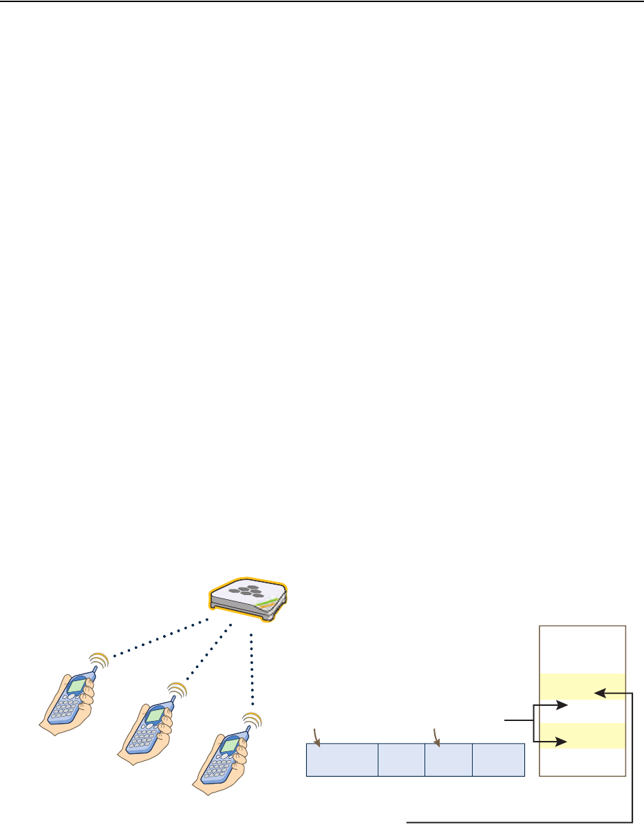
After VoIP clients associate with an SSID and begin sending traffic, the HiveAP maps all DNS and DHCP traffic to class
5, all TFTP and HTTP traffic to class 2, and all remaining traffic—voice traffic in this case—to class 6 (see Figure 7).
Figure 7 MAC OUI and Service Classifier Maps for VoIP Phones
01:22:34:BF:6C:04
01:22:34:5D:00:02
01:22:34:57:0B:3F
Data
L3
Header L4
Header
Wireless L2
Header
Destination Port Number
HiveAP
Aerohive Class
7
6
5
4
3
2
1
0
When the destination port number in the L4
header is 53 (DNS) or 67 (DHCP), the
HiveAP maps the packet to Aerohive class 5.
When it is 69 (TFTP) or 80 (HTTP), the
HiveAP maps it to Aerohive class 2.
When the MAC OUI in the L2 header is
01:22:34, the HiveAP maps the packet to
Aerohive class 6.
HiveAP
VoIP Phones from the same
vendor (MAC OUI 01:22:34)
MAC OUI

Chapter 8 HiveManager Configuration Examples
98 Aerohive
By distinguishing voice traffic by the clients’ OUI and mapping it to class 6, HiveAPs can prioritize it above other
traffic types (see "Example 4: Creating User Profiles" on page 113).
1. Log in to the HiveManager GUI.
2. Click Configuration > Network Objects > MAC Addresses/OUIs > New.
3. Enter the following, and then click Save:
•MAC OUI: (select)
• MAC Name: Type a name such as "VoIP_Phones". You cannot include any spaces when defining a MAC name.
Enter the following, and then click Apply:
• MAC Entry: Type the OUI for the VoIP phones used in the network; that is, type the first six numbers
constituting the vendor prefix of the MAC address. For example, if a MAC address is 01:22:34:AB:6C:04,
the OUI is 01:22:34. Type only the hexadecimal numerals without any formatting symbols such as colons
or dashes. If you do type such symbols, the GUI ignores—and does not display—them.
•Type: Choose Global because you do not need to restrict this network object to a particular set of
HiveAPs, which is what the other three options allow you to do.
• Description: Type a meaningful comment for the MAC OUI, such as the vendor that the OUI identifies.
Mapping the MAC OUI and Services to Aerohive Classes
First, map VoIP phone MAC OUIs to Aerohive class 6. Next, map DNS and DHCP services to Aerohive class 5 and TFTP
and HTTP services to class 2. Because voice traffic is the only remaining type of traffic from phones whose MAC OUIs
you have already mapped to class 6, HiveAPs map voice traffic from those phones to class 6. Although all these
services are critical for IP telephony to function properly, voice traffic is the least resistant to delay, and TFTP and
HTTP file downloads are the most resistant. Therefore, you prioritize the different types of traffic accordingly.
1. Click Configuration > QoS Policies > Classifiers and Markers > New.
The New Classifiers and Markers dialog box appears.
2. Enter the following, and then click Save:
• Name: VoIP-QoS (You cannot include any spaces when defining a QoS policy name.)
• Description: Add a descriptive comment, such as "Mapping for VoIP phone traffic".
• Network Services: (select)
• MAC OUIs: (select)
3. Click Configuration > QoS Policies > Classifier Maps > New > General.
The New Classifier Maps dialog box appears.
4. Enter the following on the General page:
• Name: VoIP-Mapping (You cannot include any spaces when defining the name of a classifier map.)
• Description: Add a descriptive comment, such as "Mapping services and OUIs for VoIP phone traffic".
• Network Services: (select)
• MAC OUIs: (select)
Note: If there are phones from more than one vendor, make a separate MAC OUI entry for each one.
Deployment Guide 99
EXAMPLE 2: DEFINING NETWORK OBJECTS AND MAC FILTERS
5. Click the Network Services tab, enter the following, and then click Apply:
•Service: DNS
• QoS Class: 5 - Video
•Action: Permit
• Logging: Select the check box to enable HiveAPs to log traffic that matches the service-to-Aerohive class
mapping. (HiveAPs log traffic whether the action is permit or deny.) The main use of logging traffic is to see
if the HiveAPs are receiving expected—or unexpected—types of traffic when you debug connectivity issues.
You can see the log entries in the event log on the HiveAPs (show logging buffered). Also, if you
configure the HiveAP to send event logs to a syslog server, you can see the log entries there (see "Example
6: Setting Management Service Parameters" on page 120).
6. Enter the following, and then click Apply:
•Service: DHCP-Server
• QoS Class: 5 - Video
•Action: Permit
• Logging: Select the check box to enable traffic logging, or clear the check box to disable it.
7. Enter the following, and then click Apply:
•Service: TFTP
• QoS Class: 2 - Best Effort 1
•Action: Permit
• Logging: Select the check box to enable traffic logging, or clear the check box to disable it.
8. Enter the following, and then click Apply:
•Service: HTTP
• QoS Class: 2 - Best Effort 1
•Action: Permit
• Logging: Select the check box to enable traffic logging, or clear the check box to disable it.
9. Click the MAC OUIs tab, click New, enter the following, and then click Apply:
• MAC OUIs: Choose the name of the MAC OUI that you defined in "Defining a MAC OUI", such as "VoIP_Phones".
• QoS Class: 6 - Voice
•Action: Permit
• Comment: Enter a meaningful comment about the MAC OUI for future reference.
• Logging: Select the check box to enable log traffic that matches the MAC OUI-to-Aerohive class mapping, or
clear the check box to disable it.
10. To save the configuration and close the dialog box, click Save.
Chapter 8 HiveManager Configuration Examples
100 Aerohive
Defining VLANs
You define three VLANs that you will later assign to various user profiles (see "Example 4: Creating User Profiles" on
page 113). By assigning different VLANs to different user roles, their traffic remains isolated from each other; that
is, voice traffic never shares a broadcast domain with data traffic; and data traffic from guests never shares the
same broadcast domain with employee data traffic. The result is that you can provide access for certain types of
traffic to select areas of the network while blocking unauthorized access to other areas.
The VLAN IDs and the user profiles to which you will assign them are as follows:
• VLAN ID 1 for the Emp and IT user profiles (and for users not yet registered through a captive web portal)1
• VLAN ID 2 for the VoIP user profile
• VLAN ID 3 for the Guests user profile
1. Click Configuration > Network Objects > VLANs > New, enter the following, and then click Save:
• VLAN Name: VLAN-1-EmployeeData
• Enter the following, and then click Apply:
•VLAN ID: 1
•Type: Global
•Description: VLAN for Emp, IT, and unregistered CWP users
2. Click Configuration > Network Objects > VLANs > (check box) VLAN-1-EmployeeData > Clone, make the
following changes, and then click Save:
• VLAN Name: VLAN-2-EmployeeVoice
•VLAN ID: 2
•Type: Global
•Description: VLAN for VoIP traffic
3. Click Configuration > Network Objects > VLANs > (check box) VLAN-2-VoIP > Clone, make the following
changes, and then click Save:
• VLAN Name: VLAN-3-Guests
•VLAN ID: 2
•Type: Global
•Description: VLAN for guests visiting corporate
1. There is a predefined VLAN definition for VLAN ID 1, so it is not really necessary to create a new VLAN object for it. However,
because later examples in this chapter refer to VLAN 1 by the name defined here ("VLAN-1-EmployeeData"), its purpose will
hopefully be clearer than if it were referred to by the simpler name of the predefined VLAN ("1").
Note: When defining the following VLANs, choose Global as the VLAN type because you do not need to restrict
these VLANs to a particular set of HiveAPs, which is what the other three options allow you to do.
Deployment Guide 101
EXAMPLE 2: DEFINING NETWORK OBJECTS AND MAC FILTERS
Creating IP Addresses
You use the IP addresses that you create here when defining management services for the HiveAPs (see "Example 6:
Setting Management Service Parameters" on page 120). The IP addresses are used for DNS, SNMP, syslog, and NTP
servers. To understand the locations of the different servers on the network, see Figure 15 on page 120.
DNS Servers
1. Click Configuration > Network Objects > IP Addresses > New, and after entering all the following, click Save:
•Address Name: DNS-Primary
Enter the following, and then click Apply:
— IP Address: 10.1.1.25
—Netmask: 255.255.255.255
—Type: Classifier
—Value: Tag 1: hq
By classifying the IP address definition as "hq" and then later classifying all HiveAPs deployed at
headquarters as "hq", only those HiveAPs will use the 10.1.1.25 address for their primary DNS
server.
—Description: Primary DNS server located at HQ
Enter the following, and then click Apply:
— IP Address: 10.2.2.251
—Netmask: 255.255.255.255
—Type: Classifier
—Value: Tag 1: branch1
By classifying the IP address definition as "branch1" and then later classifying all HiveAPs deployed
at the branch site as "branch1", only those HiveAPs will use the 10.2.2.251 address for their primary
DNS server. Classifying the different IP address definitions within the same IP address object allows
you to use this one object in multiple locations that have different addressing schemes.
2. Click Configuration > Network Objects > IP Addresses > New, and after entering all the following, click Save:
•Address Name: DNS-Secondary
Enter the following, and then click Apply:
— IP Address: 10.1.1.26
—Netmask: 255.255.255.255
—Type: Global
Because all the HiveAPs at both the headquarters and branch site use the same secondary DNS
server, you classify it as Global. The server is located at headquarters and HiveAPs at the branch
site reach it through a VPN tunnel.
—Description: Secondary DNS server located at HQ
Chapter 8 HiveManager Configuration Examples
102 Aerohive
Syslog Server
Click Configuration > Network Objects > IP Addresses > New, and after entering all the following, click Save:
•Address Name: Syslog-Server
Enter the following, and then click Apply:
— IP Address: 10.1.1.23
—Netmask: 255.255.255.255
—Type: Global
Because all the HiveAPs at both the headquarters and branch site use the same syslog server, you
classify it as Global. The HiveAPs at the branch site reach the syslog server, which is also located at
headquarters, through a VPN tunnel.
—Description: Syslog server at HQ
SNMP Server
Click Configuration > Network Objects > IP Addresses > (check box) Syslog-Server > Clone, change the
following settings, click Save:
•Address Name: SNMP-Server
— IP Address: 10.1.1.24 (This is the IP address of the SNMP management system to which the SNMP
agent running on the HiveAPs sends SNMP traps.)
—Description: SNMP server at HQ
NTP Server
Click Configuration > Network Objects > IP Addresses > (check box) SNMP-Server > Clone, change the
following settings, click Save:
•Address Name: NTP-Server
— IP Address: 207.126.97.57
—Description: NTP admin wjones@time.org
RADIUS Servers
1. Click Configuration > Network Objects > IP Addresses > New, and after entering all the following, click Save:
•Address Name: RADIUS-Server-Primary
Enter the following, and then click Apply:
— IP Address: 10.1.1.15
—Netmask: 255.255.255.255
—Type: Global
Because all the HiveAPs at both the headquarters and branch site use the same RADIUS servers, you
classify them as Global. The HiveAPs at the branch site reach the RADIUS servers, which are also
located at headquarters, through a VPN tunnel.
—Description: Primary RADIUS server at HQ
2. Click Configuration > Network Objects > IP Addresses > (check box) RADIUS-Server-Primary > Clone, and
after making the following changes, click Save:
•Address Name: RADIUS-Server-Secondary
— IP Address: 10.1.2.16
—Description: Secondary RADIUS server at HQ
Deployment Guide 103
EXAMPLE 2: DEFINING NETWORK OBJECTS AND MAC FILTERS
Creating a MAC Filter
A MAC filter is a type of security policy that you can apply to an SSID to allow or deny access to clients attempting to
form associations based on their source MAC addresses. In this example, you define a MAC filter based on the VoIP
phone OUI and apply it to the SSID to which you want VoIP clients to associate. HiveAPs can then filter association
requests and respond only to clients whose OUI matches that in the filter (see "Example 5: Setting SSIDs" on
page 117).
The MAC filter that you create here becomes useful when you define the SSID for voice traffic (see "voip SSID" on
page 118). You apply this filter to the SSID so that only VoIP phones with the MAC OUI 01:22:34 can form an
association with the HiveAPs.
1. Click Configuration > Security Policies > MAC Filters > New.
The New MAC Filters dialog box appears.
2. Enter the following name and description for the MAC filter:
• Name: corpVoIPphones (You cannot include any spaces when defining a MAC filter name.)
•Description: Use this filter for "voip" SSID
Choose the name that you gave the OUI, such as "VoIP_Phones" (see "Defining a MAC OUI" on page 97) from the
MAC Address/OUI drop-down list, choose Permit as the action, and then click Apply.
3. To save the MAC filter configuration and close the dialog box, click Create.
Chapter 8 HiveManager Configuration Examples
104 Aerohive
EXAMPLE 3: PROVIDING GUEST ACCESS
As a convenience for guests visiting the corporate headquarters or branch office, you provide them with wireless
network access. To preserve bandwidth for employees, the rate limit for guests is somewhat minimized. To maintain
security, visitors are restricted to accessing just the public LAN.
Two approaches are presented in this section:
•"Guest Access with Preshared Keys": This approach provides visitors with secured network access by using WPA
or WPA2 with preshared keys and TKIP or CCMP (AES) encryption. It does not include a means for enforcing
visitors to accept a network usage policy before receiving network access.
•"Guest Access with Captive Web Portal" on page 105: A captive web portal is a way to control network access by
requiring users to authenticate or register before assigning them network and user profile settings that allow
them network access beyond the HiveAP with which they associated. With this approach, registered visitors’
activity can be tracked and stored in historical logs on a syslog server for security and compliance auditing.
For the first approach, no extra configuration is necessary other than configuring a guest user profile and SSID. For
the second approach, you might want to customize the registration form used on the captive web portal. To do that,
see "Customizing the Registration Page" on page 108 and "Loading Customized Captive Web Portal Files" on page 111.
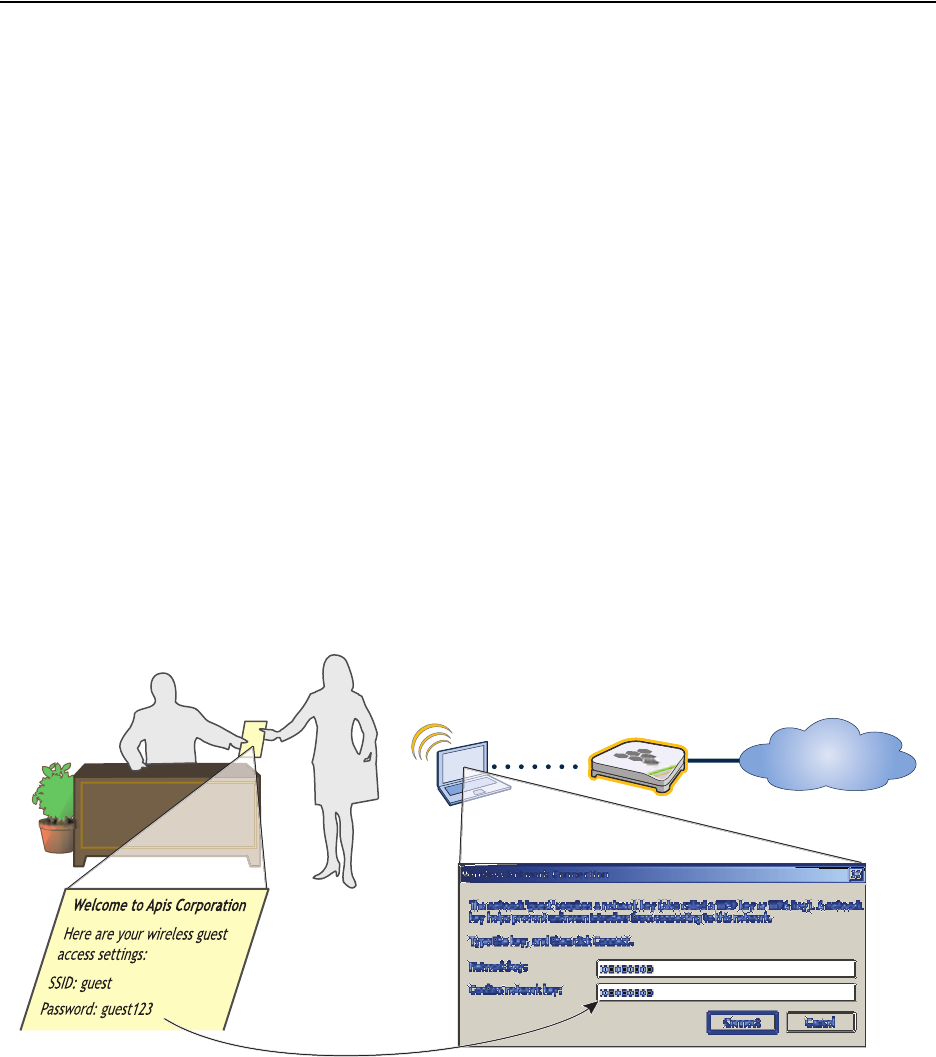
Guest Access with Preshared Keys
You can provide visitors with secure but unregistered network access by issuing them a preshared key to use when
associating with the guest SSID. A receptionist can provide visitors with the preshared key along with access
instructions upon their arrival, as shown in Figure 8.
Figure 8 Guest Access Using a Preshared Key
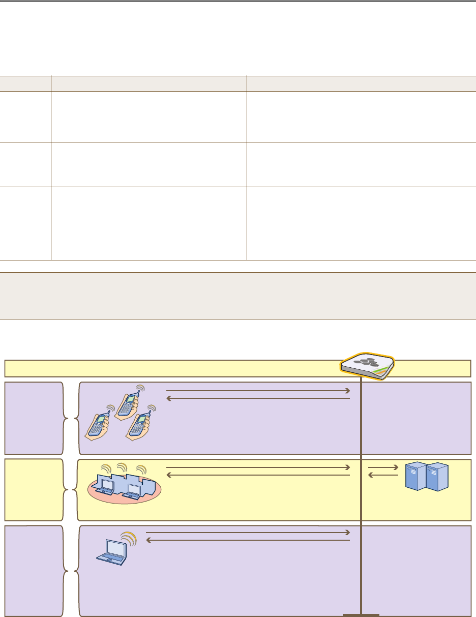
The guest SSID provides secure network access for visitors. Also, by linking visitors to the guest SSID, you can
differentiate them from employees—who associate with other SSIDs (voip and corp)—so that you can apply one set
of QoS (Quality of Service) settings for visitors and other settings for employees. In addition, the user profiles for
employees and guests further separate their traffic into two different VLANs. For instructions on setting up guest
access with a preshared key, see "Guests QoS and User Profile" on page 115 and "guest SSID" on page 119.
Receptionist Visitor
Visitor’s Laptop HiveAP
Internet
The visitor enters the
preshared key
“guest123” when
forming an association
with the HiveAP using
the SSID “guest”.
Deployment Guide 105
EXAMPLE 3: PROVIDING GUEST ACCESS
Guest Access with Captive Web Portal
A captive web portal provides registered users with network access while containing unregistered users. Aerohive
offers two approaches to applying a captive web portal, one using external DHCP and DNS servers on the network
and the other using internal DHCP and DNS servers on the HiveAP itself. In the first approach, both registered and
unregistered users must be in the same VLAN because the DHCP and DNS servers that they use initially before they
register will be the same ones that they continue using after they register. In the second approach, you can separate
the unregistered and registered users into two separate VLANs because the unregistered users access the internal
DHCP and DNS servers on the HiveAPs, whereas the registered users access the external DHCP and DNS servers,
which can be in a different VLAN from the internal servers on the HiveAP.
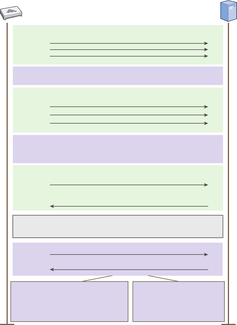
Captive Web Portal with External DHCP and DNS Servers
With this approach, when the client of a previously unregistered visitor first associates with the guest SSID, the
HiveAP assigns the "Unregistered-Guests" user profile to the visitor. It allows DHCP and DNS traffic to pass through so
that the client can receive its address and TCP/IP assignments and resolve domain names to IP addresses. It also
allows ICMP traffic for diagnostic purposes. However, the HiveAP intercepts all HTTP and HTTPS traffic from that
client—and drops all other types of traffic—thereby limiting its network access to just the HiveAP with which it
associated. No matter what website the visitor tries to reach, the HiveAP directs the visitor’s browser to a
registration page. After the visitor registers, the HiveAP stores the client’s MAC address as a registered user, applies
the "Guests" user profile to the visitor, and stops keeping the client captive; that is, the HiveAP no longer intercepts
HTTP and HTTPS traffic from that MAC address, but allows the client to access external web servers. The entire
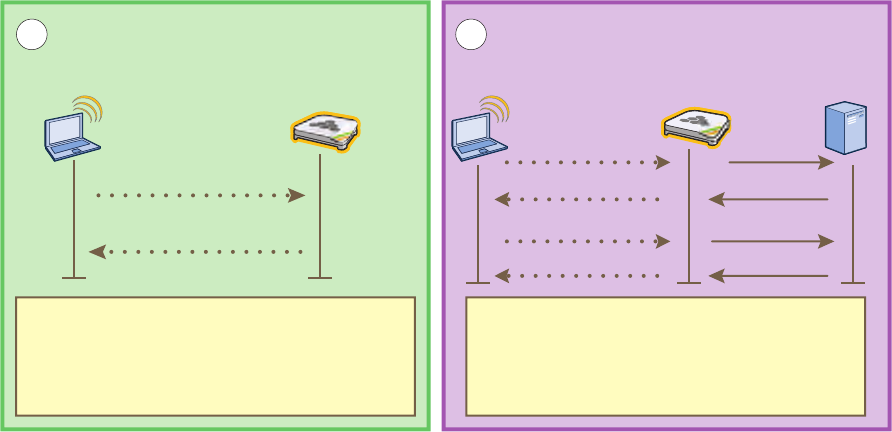
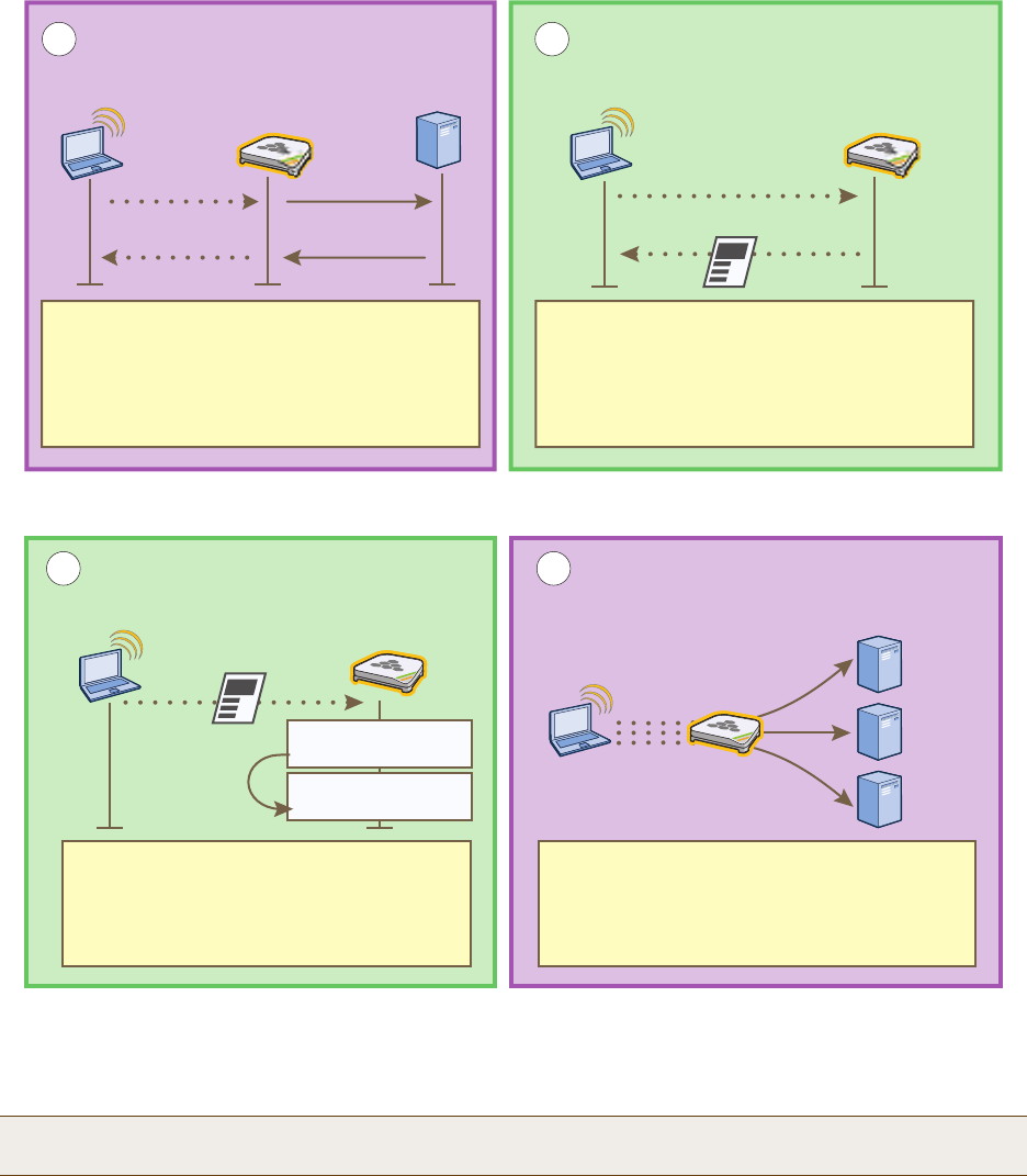
process is shown in Figure 9.
Figure 9 Captive Web Portal Exchanges Using External DHCP and DNS Servers
Wireless Client Wireless Access Point DHCP Client DHCP Server
Association Using SSID “guest” Address and TCP/IP Assignments
Association Request
Association Response
12
DHCP Request
DHCP ACK
DHCP Discover
DHCP Offer
The client forms an association with the HiveAP
but the visitor has not yet registered. The
HiveAP allows DHCP, DNS, and ICMP traffic
through. It redirects all HTTP and HTTPS traffic
to its own web server and drops all other traffic.
The HiveAP allows DHCP traffic to pass
between the client of an unregistered user and
a DHCP server so that the client can receive
its IP address and TCP/IP assignments.
Chapter 8 HiveManager Configuration Examples
106 Aerohive
To enable the captive web portal to forward DHCP and DNS traffic from unregistered users to external servers on the
network, click Configuration > Authentication > Captive Web Portal > New, and select Use external DHCP and
DNS servers on the network.
Note: With this captive web portal implementation, you must assign unregistered and registered users to the
same VLAN.
3 4
DNS Querient DNS Server HTTP Client HTTP Server
DNS Address Resolution HTTP Connection to the Captive Web Portal
HTTP GET
Reply
When the client sends an HTTP or HTTPS
GET command, the HiveAP intercepts it and
sends it to its HTTP server, which replies with
a guest access registration page. The user
must agree to an acceptable use policy, fill in
some fields, and then submit the form.
The HiveAP allows DNS queries and replies
between the client of an ungregistered user
and a DNS server
DNS Query
DNS Reply
HTTP Client HTTP Server Wireless
Client Servers
Registration DHCP, DNS, and HTTP Forwarding
56
Wireless
Acess Point
After a guest agrees to the acceptable use
policy, fills in the form, and submits the
registration, the HiveAP moves the client’s
MAC address from a quarantined list to a
registered list.
The HiveAP then applies the registered user
profile “Guests” and forwards all types of traffic
to the rest of the network, as permitted by
firewall policies assigned to that user profile.
Registration
Quarantine
MAC: 0016:cf8c:57bc
Registered
MAC: 0016:cf8c:57bc
DHCP
DNS
HTTP
Deployment Guide 107
EXAMPLE 3: PROVIDING GUEST ACCESS
Captive Web Portal with Internal DHCP and DNS Servers
With this approach, when the client of a previously unregistered visitor first associates with the guest SSID, the
HiveAP acts as a DHCP server, DNS server, and web server, limiting the client’s network access to just the HiveAP
with which it associated. No matter what website the visitor tries to reach, the HiveAP directs the browser to a
registration page. After the visitor registers, the HiveAP stores the client’s MAC address as a registered user and
stops keeping the station captive; that is, the HiveAP no longer acts as a DHCP, DNS, and web server for traffic from
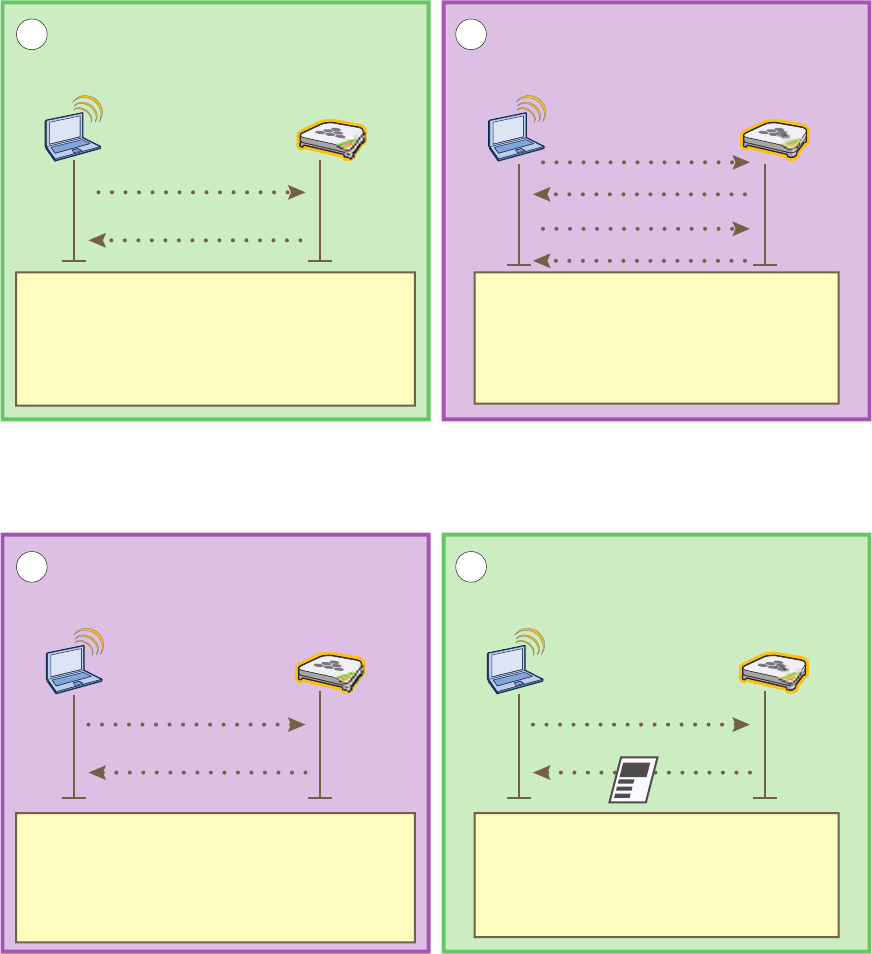
that MAC address, but allows the client to access external servers. The entire process is shown in Figure 10.
Figure 10 Captive Web Portal Exchanges Using Internal Servers
Wireless Client Wireless Access Point DHCP Client DHCP Server
Association Using SSID “guest” Address and TCP/IP Assignments
Association Request
Association Response
12
DHCP Request
DHCP ACK
DHCP Discover
DHCP Offer
SSID “guest”
The client forms an association with the HiveAP
but the visitor has not yet registered. The
HiveAP directs all DHCP, DNS, and HTTP
traffic from unregistered guests to itself instead
of allowing it to the rest of the network.
IP Address: 172.16.1.2
Netmask: 255.255.255.0
Default Gateway: 172.16.1.1*
DHCP Server: 172.16.1.1*
DNS: 172.16.1.1*
Lease: 10 Seconds
* By default, a HiveAP assigns IP addresses to
subinterfaces for captive web portal use as follows:
wifi0.1 – wifi0.7 172.16.1.1 – 172.16.7.1
wifi1.1 – wifi1.7 172.16.11.1 – 172.16.17.1
3 4
DNS Querient DNS Server HTTP Client HTTP Server
DNS Address Resolution HTTP Connection to the Captive Web Portal
DNS Query
DNS Reply
HTTP GET
Reply
When the HTTP client sends a GET
command, the HTTP server replies with a
guest access registration page. The user
must agree to an acceptable use policy, fill
in some fields, and then submit the form.
Wildcard A record in the root zone “.” on the
HiveAP DNS server: * in a 172.16.1.1
The DNS server resolves all domain
name-to-address queries to the same IP
address, which in this case is 172.16.1.1.
Chapter 8 HiveManager Configuration Examples
108 Aerohive
To enable the captive web portal to forward DHCP and DNS traffic from unregistered users to its internal servers,
click Configuration > Authentication > Captive Web Portal > New, and select Use internal DHCP and DNS servers
on the HiveAP. By default, the internal DHCP server issues leases with a ten-second lifetime, and if a client with a
nonexistent lease requests a lease renewal, the HiveAP responds by broadcasting a DHCP NAK. You can change the
HiveAP response so that it sends a unicast NAK or ignores the request completely (Keep Silent).
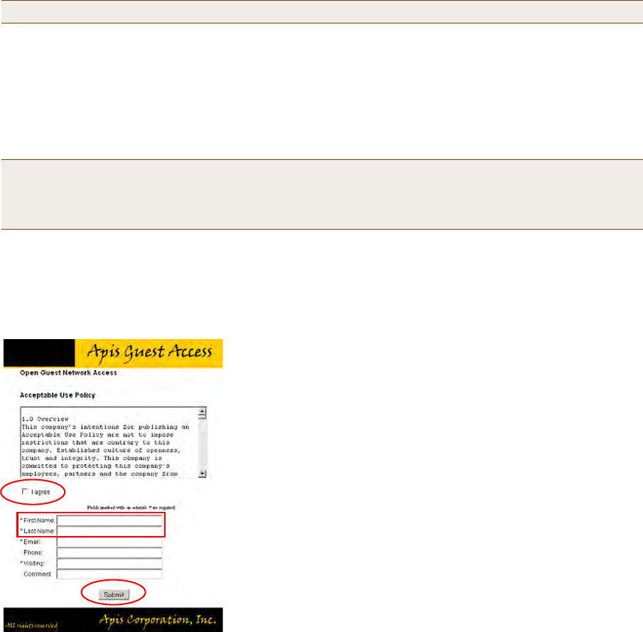
Customizing the Registration Page
Although Aerohive provides .html and .jpg files for use on the captive web portal server, you might want to
customize them to better suit your organization. There are six files, four of which are shown in Figure 11:
Note: With this captive web portal implementation, you can assign unregistered and registered users to the same
VLAN or to different VLANs.
• index.html (the main registration page) • loginscreen_02.jpg (image at the top of web pages)
• success.html (page that appears after registering) • loginscreen_03.jpg (yellow line near top of web pages)
• reg.php (script stored on internal web server) • loginscreen_05.jpg (image at bottom of index.html)
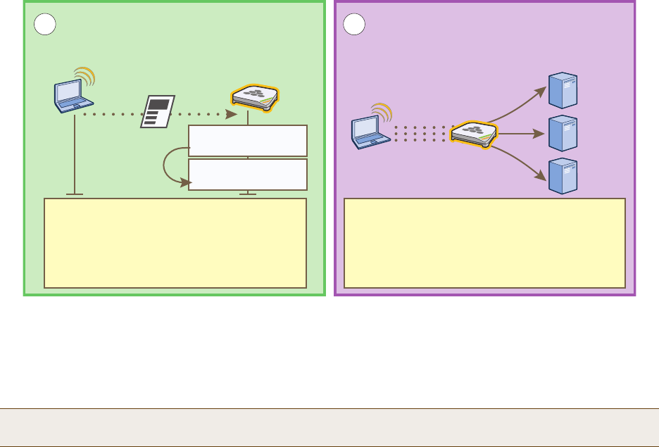
HTTP Client HTTP Server Wireless
Client Servers
Registration DHCP, DNS, and HTTP Forwarding
56
Wireless
Acess Point
After a guest agrees to the acceptable use
policy, fills in the form, and submits the
registration, the HiveAP moves the client’s
MAC address from a quarantined list to a
registered list.
The HiveAP applies the “Guests” user profile
and forwards further DHCP, DNS, and HTTP
requests to external servers on the network.
Because the DHCP lease is only 10 seconds,
the transition to the external servers occurs
very soon after the registration completes.
Registration
Quarantine
MAC: 0016:cf8c:57bc
Registered
MAC: 0016:cf8c:57bc
DHCP
DNS
HTTP
Deployment Guide 109
EXAMPLE 3: PROVIDING GUEST ACCESS
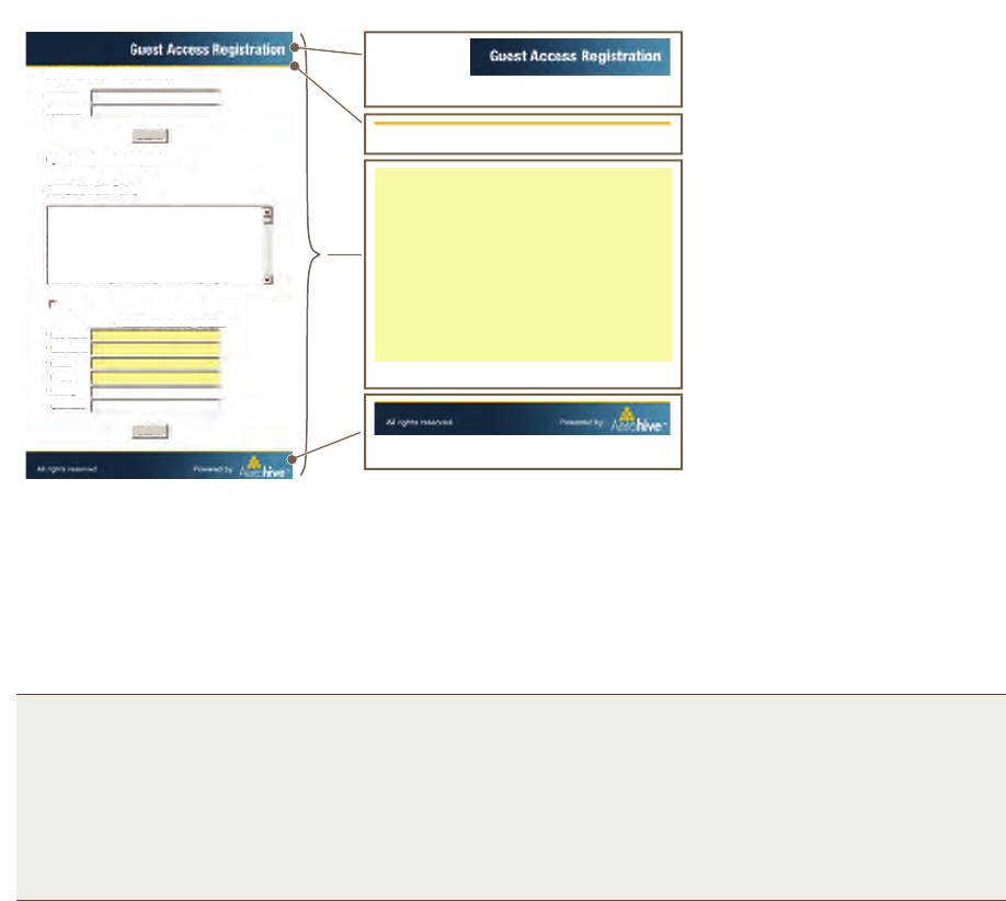
Figure 11 Captive Web Portal Registration Page
Unregistered users’ browsers are redirected to the registration page (index.html) of the captive web portal for the
SSID to which they associate (the guest SSID in the examples here). You can have a different registration page for
each SSID.
To access the default set of .html and .jpg files on a HiveAP, do the following:
1. Configure a guest SSID as explained in "guest SSID" on page 119 and complete the rest of the HiveAP steps
explained in this chapter to bring a HiveAP under HiveManager management.
2. Position your management system near the HiveAP and form an association with it using the guest SSID.
3. Open a web browser. When it tries to open its home page, the HiveAP intercepts the HTTP traffic and redirects
it to the captive portal web server.
4. Save the registration page to your local system. In Microsoft Internet Explorer®, for example, click File >
Save As, name it index, and in the Save as type field, choose Webpage, complete (*.htm, *.html).
5. Open the directory where you saved the index.html file.
In addition to the index.html file, there is also an images directory containing the three .jpg files that
index.html references: loginscreen_02.jpg, loginscreen_03.jpg, and loginscreen_05.jpg.
6. Because the directory structure in the HiveAP is different, move the three .jpg files to the same directory as
index.html. Optionally, delete those three images and create your own new images, saving them in the same
directory as the index.html file.
7. Open index.html with a text editor and make the following changes:
Note: An alternative approach is to log in to the console port of an individual HiveAP that you have
connected to the network—see "Step 1 Log in through the console port" on page 150—and enter the
following commands:
ssid guest
ssid guest security additional-auth-method captive-web-portal
interface wifi0 ssid guest
save config
loginscreen_02.jpg (304 x 56 px)
loginscreen_05.jpg (450 x 50 px)
<html>
<head>
<title>loginscreen</title>
<meta http-equiv="Content-Type"
content="text/html; charset=iso-8859-1">
<style type="text/css">
<!--
.style1 {
font-family: Arial, Helvetica,
sans-serif;
font-weight: bold;
font-size: 14px;
}
. . .
index.html
loginscreen_03.jpg (450 x 4 px)
Note: The resolution for all images
is 96 dpi. The bit depth is 24.
To modify the registration page,
do the following:
1. Set up a captive web portal on
an SSID.
2. Acting as a client, make an
association with that SSID.
3. When you see the registration
page in your browser, save it
and its accompanying images.
4. Use a graphics program to
create new .jpg images.
5. Use a text editor to modify the
text in the index.html file.
6. Upload the files to the HiveAP.
http://www.cwp-login-0-1.com/index.html
Authenticated Network Access
User Name:
Password:
Open Guest Network Access
Acceptable Use Policy
Submit
Submit
I agree
First Name:
Last Name:
Email:
Phone:
Visiting:
Comment:
*
*
*
*
Fields marked with an asterisk * are required.
1.0 Overview
This company’s intentions for publishing an
Acceptable Use Policy are not to impose
restrictions that are contrary to this
company. Established culture of openness,
trust and integrity. This company is
committed to protecting this company’s
Chapter 8 HiveManager Configuration Examples
110 Aerohive
• Remove the string index_files/ from the image source definitions of the three images:
<img src="index_files/loginscreen_02.jpg" width="304" height="56" alt="">
<img src="index_files/loginscreen_03.jpg" width="450" height="4" alt="">
<img src="index_files/loginscreen_05.jpg" width="450" height="50" alt="">
• To change the color in the bar in the upper left corner, find <td width="146" bgcolor="002740">
and enter a different color definition. For example, to make it black, enter "000000".
• If you want to change the acceptable use policy, find the section that begins with the words
"1.0 Overview", and then either replace the text with your own policy or edit the existing one.
• To remove the Authenticated Network Access section at the top of the page, delete the HTML code from
"<FORM name=form2 action=reg.php method=post>" to "</DIV></FORM>".
Figure 12 on page 110 shows the result of editing the text in the acceptable use policy, changing the color in the
top left bar in the index.html file, creating two new images for loginscreen_02.jpg and loginscreen_05.jpg, and
removing the Authenticated Network Access section.
Figure 12 Modified Registration Page
8. To edit the "Successful Registration" page, which follows the registration page, click I agree, fill in the fields,
and then click Submit Query.
The browser opens the "Successful Registration" page.
9. Save the page as a file named success.html to the same directory as the index.html file.
10. Open it with a text editor, make your changes, and then save the modified file.
Note: When working on image files, make sure that they match the above dimensions.
Note: If you want to use the Authenticated Network Access section to authenticate employees through the
captive web portal, store their user accounts on the RADIUS server that you configure in "Example 7:
Defining AAA RADIUS Settings" on page 123. The HiveAPs hosting the captive web portal will forward
their user name and password entries to that RADIUS server for the authentication check.
Notes
The default registration page contains two forms: an upper form
for user authentication (through an external RADIUS server)
and a lower form for user registration. In this example, you
remove the upper form so that the page is simply for guest
registration.
The total number of fields in the customized file shown here is
the same as that in the default index.html file. If you want, you
can edit the HTML code to change the number of required and
optional fields. (Fields identified as "INPUT id=field<number>"
are required, and "INPUT id=opt_field<number>" are optional.)
If you change the number of fields in the HTML code, you must
also change them in the captive web portal section of the SSID
configuration.
There are some elements that cannot be removed from this file:
• "I agree" check box (its name must remain as “checkbox” in
the code)
• "First Name" and "Last Name" fields—they are used to
identify users in the roaming cache and event log
• Submit button

Deployment Guide 111
EXAMPLE 3: PROVIDING GUEST ACCESS
Loading Customized Captive Web Portal Files
To load your edited or new files onto one or more HiveAPs, you first create a directory on HiveManager and then
upload the files from your management system or SCP (Secure Copy) server into that directory. From there, you can
send the files to one or more managed HiveAPs when you push the configuration that references the files.
To create a directory on HiveManager and upload files into it, do the following:
1. In the HiveManager GUI, click Configuration > HiveAP File Management.
2. In the HiveAP File Management window, select Captive Portal Page for file type.
Two display areas (Available Directories and Available CWP Files) and a new field (Directory Name) appear.
3. In the Directory Name field, type a name such as guestCWP, and then click Create.
A directory named "guestCWP" appears in the Available Directories list.
4. Depending on how you upload the files, select
guestCWP
, enter one of the following, and then click
Upload
:
To load files from a directory on your local management system:
•Local File: (select); type the directory path and a file name; or click Browse, navigate to one of the files,
and select it.
or
To load a file from an SCP server:
•SCP Server: (select)
• IP Address: Enter the IP address of the SCP server.
• SCP Port: Enter the port number of the SCP server (the default port number for SCP is 22).
• File Path: Enter the directory path and file name. If the files are in the root directory of the SCP server, you
can simply enter the file name.
• User Name: Type a user name with which HiveManager can access the SCP server.
• Password: Type a password with which HiveManager can use to log in securely to the SCP server.
5. Repeat either the Local or SCP method of uploading each file you need into the guestCWP directory.
Note: After you load a file, it appears in the Available CWP Files display area. If you accidentally load the
wrong file, select the file name and then click Remove.

Chapter 8 HiveManager Configuration Examples
112 Aerohive
Defining a Captive Web Portal
Define the following captive web portal for use when creating an SSID for guest registration (see "guest SSID" on
page 119). The definition below references the web directory "guestCWP" and the HTML files that you modified and
uploaded in the previous section—login.html and success.html.
Click Configuration > Authentication > Captive Web Portal > New, enter the following, leave all the other
values at their default settings, and then click Save:
• Name: CWP-guest1
•Description: Captive web portal for guest registration
• Use default file settings: (clear)
•Web Files Directory: guestCWP
•Web Page Name: login.html
•Result Page Name: success.html
• Use external DHCP and DNS servers on network: (select)
Perform the following tasks to finish setting up the captive web portal:
• Configure two user profiles—one for successfully registered users and another for the unsuccessful (see
"Guests QoS and User Profile" on page 115 and "Unregistered-Guests QoS and User Profile" on page 116)
• Configure an SSID with captive web portal functionality (see "guest SSID" on page 119)
• Link the user profiles to the SSID in a WLAN policy (see
"Example 9: Creating WLAN Policies" on page 126
)
• Push the files and configuration to managed HiveAPs on which you want to run the portal (see "Example 10:
Assigning Configurations to HiveAPs" on page 135)
Note: You can also use the Aerohive GuestManager to provide network access to wireless visitors. An
administrator, called an operator, sets up visitors’ account on GuestManager. Then GuestManager uses its
built-in RADIUS server to authenticate those users. For more information, see the Aerohive GuestManager
Getting Started Guide.
Deployment Guide 113
EXAMPLE 4: CREATING USER PROFILES
EXAMPLE 4: CREATING USER PROFILES
User profiles contain a grouping of settings that determine the QoS (Quality of Service), VLAN, firewall policies, and
mobility policy that you want HiveAPs to apply to traffic from a specific group of users. In this example, you define
user profiles and their companion QoS forwarding rates and VLANs for VoIP phone users ("VoIP"), IT staff ("IT"),
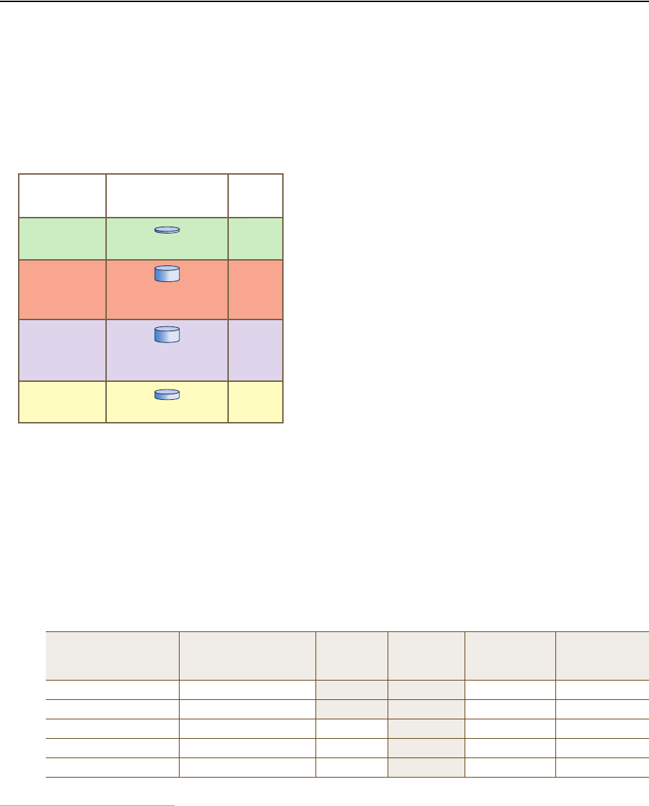
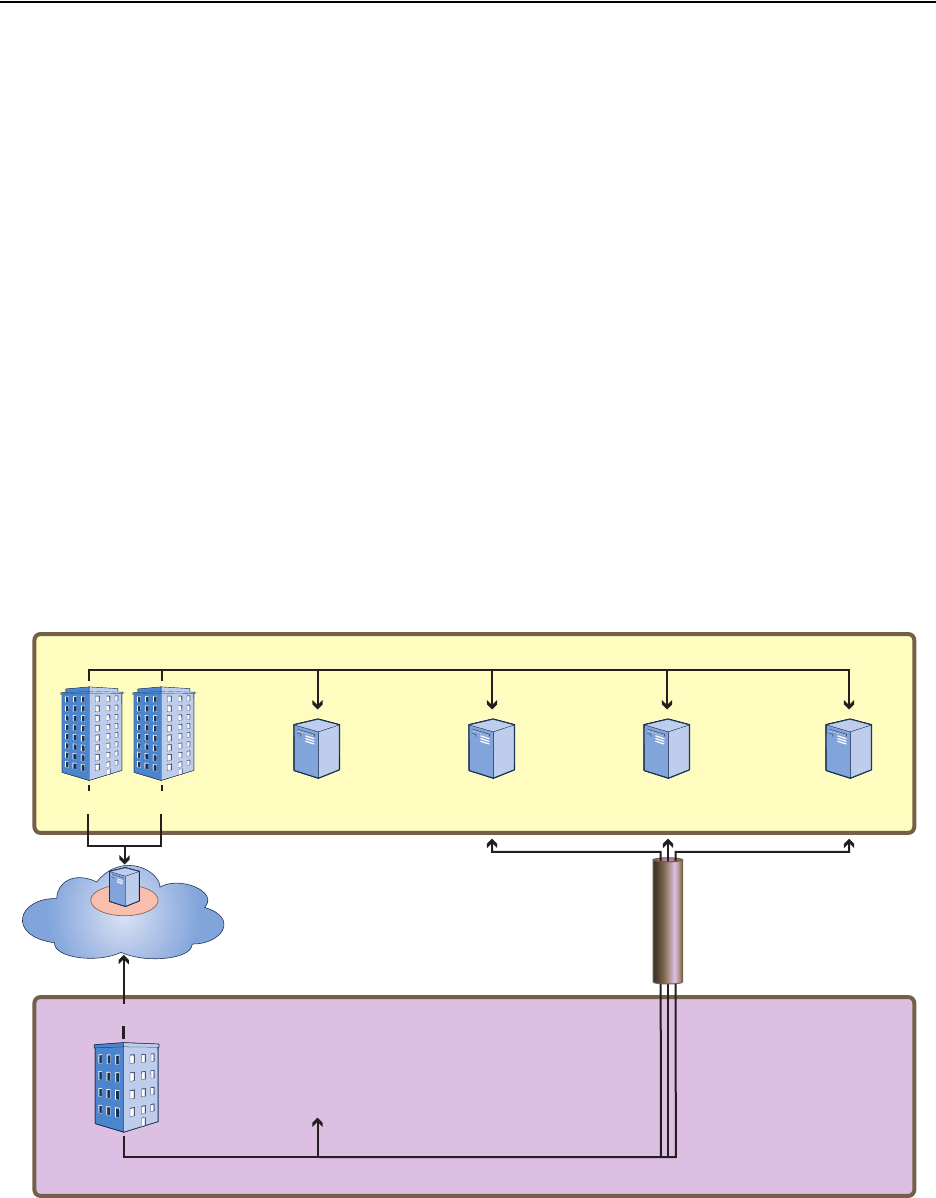
corporate employees ("Emp"), and corporate visitors ("Guests"2). The user profile settings, maximum traffic
forwarding rates per user, and the VLAN for each profile are shown in Figure 13.
Figure 13 User Profiles, Forwarding Rates per User, and Default VLANs
VoIP QoS and User Profile
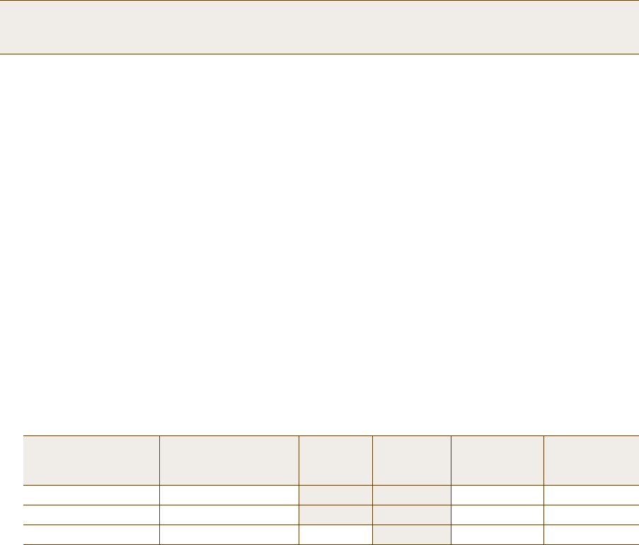
1. Click Configuration > QoS Policies > Rate Control & Queuing > New, enter the following, and then click Save:
• Name: QoS-VoIP
• Per User Rate Limit: 512 Kbps (802.11a/b/g); 512 Kbps (802.11n)
This is the maximum amount of bandwidth that a single user belonging to this profile can use. It supports a
single 8 – 64-Kbps VoIP session—depending on the voice codec used—while reserving bandwidth for other
required telephony services such as DNS, DHCP, HTTP, and TFTP.
• Description: Enter a useful comment for future reference, such as "QoS for VoIP traffic per user".
• Per User Queue Management: Enter the following items that appear in bold:
2. For guest access using a captive web portal, there must be two user profiles: one for guests that register successfully ("Guests")
and another for guests have not registered or whose registration attempt failed ("Unregistered-Guests").
Class Number - Name Scheduling Type Scheduling
Weight Weight %
(Read Only) Policing Rate
Limit (Kbps)
(802.11a/b/g)
Policing Rate
Limit (Kbps)
(802.11n)
7 - Network Control Strict 00% 512 512
6 - Voice Strict 00% 64 64
5 - Video Weighted Round Robin 60 28% 512 512
4 - Controlled Load Weighted Round Robin 50 23% 512 512
3 - Excellent Effort Weighted Round Robin 40 19% 512 512
Notes: Because individual VoIP calls use relatively little
bandwidth (~128 Kbps, depending on the voice compression
codex used), a single VoIP user does not need as much
bandwidth as a user transmitting other types of traffic.
Corporate employees—IT and Emp—receive the highest
maximum data forwarding rates.
Guests receive enough bandwidth to satisfy basic network
access but not enough to interfere with employee traffic.
Regarding VLAN assignments, each user profile is securely
isolated in its own VLAN (IT and Emp being divisions within the
larger role of employee). Note: The link connecting the HiveAP
Ethernet interface to the interface on the connecting switch
must be an 802.1Q trunk port configured to allow traffic on
these VLANs from the HiveAPs.
User Profiles
Name: VoIP
Attribute: 2
Name: IT
Attribute: 3
Name: Emp
Attribute: 4
Name: Guests
Attribute: 5
Default
VLANs
2
3
1
1
Maximum Data
Forwarding Rates
per User
11a/b/g/n 512 Kbps
11a/b/g 54000 Kbps
11n 1,000,000 Kbps
11a/b/g/n 2000 Kbps
11a/b/g 54000 Kbps
11n 1,000,000 Kbps

Chapter 8 HiveManager Configuration Examples
114 Aerohive
Because you use strict rate limiting for voice traffic, it is always assured the maximum bandwidth rate of 64
Kbps—even if the VoIP phone is updating its software or is otherwise engaged in activity other than voice traffic.
The other telephony services (DHCP and DNS mapped to Aerohive class 5, and HTTP and TFTP mapped to class
2) can function at the remaining bandwidth rate.
2. Click Configuration > User Profiles > New > General, enter the following, and then click Save:
• Name: VoIP (You cannot include any spaces when defining a user profile name.)
•Attribute: 2
Each user profile in the same WLAN must have a unique attribute number. When using a local authentication
mechanism, this attribute links the profile to an SSID so that the HiveAP applies the QoS settings for the
profile to all traffic using that SSID.
• Attribute Group: Leave this field empty.
An attribute group is a way to assign various RADIUS users with different attribute numbers to the same user
profile. Because VoIP users are not authenticated from a RADIUS server, this option is not applicable here.
•QoS Setting: QoS-VoIP
• Default VLAN: VLAN-2-EmployeeVoice (previously defined; see "Defining VLANs" on page 100)
HiveAPs assign users matching the VoIP user profile to VLAN 2. This separates all employee voice traffic
from employee data traffic, which will be on VLAN 1. Guest traffic will be on VLAN 3, separating it from
both employee data and voice traffic.
•Description: Employees using VoIP
IT Staff QoS and User Profile
1. Click Configuration > QoS Policies > Rate Control & Queuing > New, enter the following, and then click Save:
• Name: QoS-ITdata
• Per User Rate Limit: 54000 Kbps (802.11a/b/g); 1000000 Kbps (802.11n) (These are the default values.)
This is the maximum amount of bandwidth that a single user belonging to this profile can use. It is the
maximum so that even if only one IT staff member is on the network, he or she can use all the available
bandwidth if needed.
•Description: QoS per IT staff member
• Per User Queue Management: Keep all the settings at their default values.
2. Click Configuration > User Profiles > New > General, enter the following, and then click Save:
• Name: IT (You cannot include any spaces when defining a user profile name.)
•Attribute: 3
Because the attribute number for the def-user and VoIP user profiles are 1 and 2, enter "3" here. This
number can be any unique number from 3 to 63. Because you will later map this profile to an SSID that uses
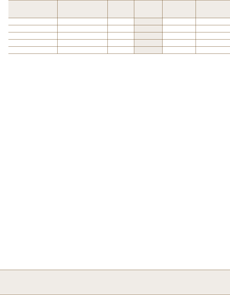
2 - Best Effort 1 Weighted Round Robin 30 14% 512 512
1 - Best Effort 2 Weighted Round Robin 20 9% 512 512
0 - Background Weighted Round Robin 10 4% 512 512
Note: The default 802.11a/b/g rate limit for Aerohive class 6 (voice) is 512 Kbps and for 802.11n it is 20,000
Kbps. These default rate limits are large enough to support conference calls, but for typical
one-to-one communications, 64 Kbps is sufficient.
Class Number - Name Scheduling Type Scheduling
Weight Weight %
(Read Only) Policing Rate
Limit (Kbps)
(802.11a/b/g)
Policing Rate
Limit (Kbps)
(802.11n)
Deployment Guide 115
EXAMPLE 4: CREATING USER PROFILES
IEEE 802.1X authentication, you must configure the user profile attribute that you set here as an attribute
on the RADIUS server as explained in "RADIUS Server Attributes" on page 124.
• Attribute Group: Leave this field empty.
•QoS Setting: QoS-ITdata
• Default VLAN: VLAN-1-EmployeeData (previously defined; see "Defining VLANs" on page 100)
HiveAPs assign users matching the IT user profile to VLAN 1. This separates all employee data traffic from
employee voice traffic, which will be on VLAN 2. Guest traffic will be on VLAN 3, separating it from both
employee data and voice traffic.
•Description: IT staff
Emp (Employees) QoS and User Profile
1. Click Configuration > QoS Policies > Rate Control & Queuing > (check box) QoS-ITdata > Clone, change the
following settings, and then click Save:
• Name: QoS-EmployeeData
•Description: QoS per regular employee
• Per User Queue Management: Keep all the settings at their default values.
2. Click Configuration > User Profiles > (check box) IT > Clone, make the following changes, and then click Save:
• Name: Emp (You cannot include any spaces when defining a user profile name.)
•Attribute: 4
Because the attribute numbers for the def-user, VoIP, and IT profiles are 1, 2, and 3 respectively, enter "4"
here. This number can be any unique number from 4 to 63. Because you will later map this profile to an SSID
that uses IEEE 802.1X authentication, you must configure the user profile attribute set here as an attribute
on the RADIUS server as explained in "RADIUS Server Attributes" on page 124.
•QoS Setting: QoS-EmployeeData
•Description: Regular employees
Guests QoS and User Profile
1. Click Configuration > QoS Policies > Rate Control & Queuing > New, enter the following, and then click Save:
• Name: QoS-Guests
• Per User Rate Limit: 2000 Kbps (802.11a/b/g); 2000 Kbps (802.11n)
This is the maximum amount of bandwidth that a single user belonging to this profile can use. It is far less
than that for employees, but should be sufficient for basic Internet and e-mail access.
•Description: QoS per guest
• Per User Queue Management: Enter the following items in bold. Leave all other cloned settings unchanged.
Note: Although the "per user rate limit" and the "per user queue management" settings are the same as those
for QoS-ITdata, you must create this QoS profile so that you can later assign different weights to
QoS-ITdata and QoS-EmployeeData (see "Example 9: Creating WLAN Policies" on page 126).
Class Number - Name Scheduling Type Scheduling
Weight Weight %
(Read Only) Policing Rate
Limit (Kbps)
(802.11a/b/g)
Policing Rate
Limit (Kbps)
(802.11n)
7 - Network Control Strict 00% 64 64
6 - Voice Strict 00% 64 64
5 - Video Weighted Round Robin 60 28% 2000 2000
Chapter 8 HiveManager Configuration Examples
116 Aerohive
2. Click Configuration > User Profiles > (check box) Emp > Clone > General, enter the following, and then click
Save:
•User Profile Name: Guests
•Attribute: 5
Each user profile in the same WLAN must have a unique attribute number. Because the attributes for the
def-user, VoIP, IT, and Emp profiles are 1, 2, 3, and 4 respectively, enter "5" here. This number can be any
unique number from 5 to 63.
• Attribute Group: Leave this field empty.
•QoS Setting: QoS-Guests
• Default VLAN: VLAN-3-Guests (previously defined; see "Defining VLANs" on page 100)
HiveAPs assign users matching the VoIP user profile to VLAN 2. This separates all employee voice traffic
from employee data traffic, which will be on VLAN 1. Guest traffic will be on VLAN 3, separating it from
both employee data and voice traffic.
•Description: Visiting guests
Unregistered-Guests QoS and User Profile
Enter the following if you are using the captive web portal approach for providing guest access (see "Guest Access
with Captive Web Portal" on page 105). A HiveAP applies this profile to users who have not yet registered, or do not
successfully register, through the captive web portal.
Click Configuration > User Profiles > (check box) Guests > Clone > General, enter the following, and then click
Save:
•User Profile Name: Unregistered-Guests
•Attribute: 6
Because each user profile attribute number must be unique and 1 – 5 have already been assigned, enter "6"
here. This number can be any unique number from 6 to 63.
• Attribute Group: Leave this field empty.
•QoS Setting: QoS-Guests
• Default VLAN: VLAN-3-Guests
•Description: CWP unregistered guests
4 - Controlled Load Weighted Round Robin 50 23% 2000 2000
3 - Excellent Effort Weighted Round Robin 40 19% 2000 2000
2 - Best Effort 1 Weighted Round Robin 30 14% 2000 2000
1 - Best Effort 2 Weighted Round Robin 20 9% 2000 2000
0 - Background Weighted Round Robin 10 4% 2000 2000
Note: In this set of examples, you enable the captive web portal method to forward DHCP and DNS traffic to
external servers. So that the clients of registered users can continue to use the network settings that
they received while they were still unregistered, you must configure both the Guests and
Unregistered-Guests profiles with the same VLAN.
Class Number - Name Scheduling Type Scheduling
Weight Weight %
(Read Only) Policing Rate
Limit (Kbps)
(802.11a/b/g)
Policing Rate
Limit (Kbps)
(802.11n)
Deployment Guide 117
EXAMPLE 5: SETTING SSIDS
EXAMPLE 5: SETTING SSIDS
An SSID (service set identifier) is an alphanumeric string that identifies a set of authentication and encryption
services that wireless clients and access points use when communicating with each other. In this example, you
define the following three SSIDs, which are also shown in Figure 14:
Figure 14 SSIDs Providing Network Access to Different Users
SSID Name Security Protocol Other
voip Key method: WPA2-PSK
Encryption method: TKIP
Preshared key (ASCII): CmFwbo1121
Authentication method: Open
A MAC filter restricts access only to VoIP phones
specified in the filter.
corp Key method: WPA2-EAP (802.1X)
Encryption method: CCMP (AES)
Authentication method: EAP (802.1X)
Employees use the RADIUS server specified in
"Example 7: Defining AAA RADIUS Settings" on
page 123 to authenticate themselves using IEEE
802.1X.
guest Key method: Auto-(WPA or WPA2)-PSK
Encryption method: Auto-TKIP or CCMP (AES)
Preshared key (ASCII): guest123
Authentication method: Open
and
for captive web portal: CWP-guest1
For guest access using a preshared key, the
receptionist supplies guests with the SSID name and
configuration details, including the preshared key,
when they arrive.
Note: You can define up to seven SSIDs for a single radio in access mode. If hive members use one radio for
wireless backhaul communications, then they must use the other radio in access mode. In this case, a
HiveAP can have a maximum of seven SSIDs. If hive members send backhaul traffic completely over wired
links, then both radios can be in access mode and a HiveAP can have a maximum of 14 SSIDs.
User Profiles SSID Definitions
SSID: corp
Key method: WPA2-802.1X (WPA2 Enterprise)
Encryption method: CCMP (AES)
Authentication method: EAP (802.1X)
SSID: voip
Key method: WPA2-PSK (WPA2 Personal)
Encryption method: TKIP
Preshared key (ASCII): CmFwbo1121
Authentication method: Open
SSID: guest
Key method: Auto-(WPA or WPA2)-PSK
Encryption method: Auto-TKIP or CCMP (AES)
Preshared key (ASCII): guest123
Authentication method: Open
and
for captive web portal: CWP-guest1
VoIP Phones
Corporate Network
Visiting Guest
at Corporate Site
HiveAP
RADIUS Servers for
802.1X Authentication
VoIP
IT
Emp
Unregistered-
Guests
(for captive
web portal)
Guests

Chapter 8 HiveManager Configuration Examples
118 Aerohive
Employees that belong to the "IT" and "Emp" profiles can use SSIDs "voip" and "corp". The SSID with which they
associate is based on how they are attempting to access the network. If they use a VoIP phone, then they associate
with the voip SSID because that is the SSID configured on their phones. If they use a wireless client on a computer,
then they associate with the corp SSID because that is the SSID configured on the wireless client on their computers.
In contrast, visitors can only associate with the guest SSID. The receptionist provides configuration details and the
preshared key for the guest SSID when visitors arrive. The guest SSID is the only wireless network choice available to
which visitors’ wireless clients can connect. When the captive web portal option is in use, HiveAPs assign visitors
who register successfully to the "Guests" profile and those who do not to the "Unregistered-Guests" profile.
voip SSID
1. Click Configuration > SSIDs > New > General, enter the following, and leave all other values at their default
settings:
• SSID: voip (You cannot include any spaces when defining the name of an SSID.)
•Description: SSID exclusively for VoIP phones
• Key Management: WPA2-PSK
• Encryption Method: TKIP
• Authentication Method: Open
•Key Type: ASCII Key
•Key Value: CmFwbo1121 (The key length can be from 8 to 63 characters.)
2. Click the Advanced tab.
3. In the Available MAC Filters list, click corpVoIPphones >, to move it to the Selected MAC Filters list, set the
Default Action as Deny, and then click Save.
By applying a MAC filter to the voip SSID, you restrict access to VoIP phones matching the specified OUI. The
corpVoIPphones MAC filter is defined in "Creating a MAC Filter" on page 103.
corp SSID
1. Click Configuration > SSIDs > New > General, enter the following, and leave all other values at their default
settings:
• SSID: corp
•Description: SSID for corporate employees
• Key Management: WPA2-EAP (802.1X)
• Encryption Method: CCMP (AES)
• Authentication Method: EAP (802.1X)
Note: You can also use Aerohive GuestManager to provide network access to wireless visitors. For information
about GuestManager, see the Aerohive GuestManager Getting Started Guide.
Deployment Guide 119
EXAMPLE 5: SETTING SSIDS
guest SSID
1. Click Configuration > SSIDs > New > General, enter the following, and leave all other values at their default
settings:
• SSID: guest
•Description: SSID for company guests
• Key Management: Auto-(WPA or WPA2)-PSK
• Encryption Method: Auto-TKIP or CCMP (AES)
• Authentication Method: Open
•Key Type: ASCII Key
•Key Value: guest123
or
On the General page, enter the following:
• SSID: guest
•Description: SSID for registering company guests
• Captive Web Portal: CWP-guest1
• Key Management: Auto-(WPA or WPA2)-PSK
• Encryption Method: Auto-TKIP or CCMP (AES)
• Authentication Method: Open
•Key Type: ASCII Key
•Key Value: guest123
Chapter 8 HiveManager Configuration Examples
120 Aerohive
EXAMPLE 6: SETTING MANAGEMENT SERVICE PARAMETERS
Management services include the settings for DNS, syslog, SNMP, NTP, and location servers. HiveAPs use these
services for network communications and logging activities. In addition, you can set HiveAP admin access
parameters.
In this example, you configure the management services that you later reference in WLAN policies (see "Example 9:
Creating WLAN Policies" on page 126). Two WLAN policies are for HiveAPs at the corporate HQ site and the third is
for HiveAPs at the remote branch office. You define the following management services:
• Three DNS (Domain Name Service) servers—one primary server at HQ, one primary server at the branch site, and
one secondary server at HQ. HiveAPs at the branch site connect to the secondary DNS server through a VPN
tunnel.
Although there are three DNS servers, there are only two IP address objects. The IP address object for the
primary DNS server has two IP address definitions. By using the classifier tags "hq" and "branch1", all HiveAPs
deployed at headquarters and classified as "hq" use the "hq" address definition, while all those deployed at the
branch site and classified as "branch1" use the "branch1" definition. Because all HiveAPs use the secondary DNS
server (at headquarters), its IP address definition is classified as Global; that is, it is the same for all HiveAPs.
• One syslog server and one SNMP (Simple Network Management Protocol) server—both at headquarters. HiveAPs
at the branch office connect to these through a VPN tunnel.
• One NTP (Network Time Protocol) server—located on the public network. HiveAPs synchronize the time on their
system clocks with this server.
The various servers and their relationship to the two sites is shown in Figure 15.
Figure 15 Location of Servers in Relation to Each WLAN Policy
Corporate Headquarters
Only the primary DNS server for the branch
office is at the branch office site. The NTP server
is on the public network. All other management
servers are at headquarters. A VPN tunnel
protects traffic between the two sites.
Primary DNS Server
10.1.1.25
Primary DNS Server
10.2.2.251
Secondary DNS Server
10.1.2.26 SNMP Server
10.1.1.24
Syslog Server
10.1.1.23
Branch Office
VPN Tunnel
Remote NTP Server
207.126.97.57
Management services at headquarters
Management services at the branch site
Deployment Guide 121
EXAMPLE 6: SETTING MANAGEMENT SERVICE PARAMETERS
DNS Assignment
Click Configuration > Management Services > DNS Assignments > New, and after entering all the following,
click Save:
• Name: DNS-Primary-HQ
•Domain Name: apis.com (This is the domain name of the corporation in this example.)
•Description: Primary and secondary DNS servers
To specify a previously defined IP address object for the primary DNS server, enter the following, and then
click Apply:
— IP Address: DNS-Primary
—Description: Primary DNS server tagged "hq" and "branch1"
To specify a previously defined IP address object for the secondary DNS server, click New, enter the
following, and then click Apply:
— IP Address: DNS-Secondary
—Description: Secondary DNS server 10.1.1.26
Syslog Assignment
Click Configuration > Management Services > Syslog Assignments > New, and after entering all the following,
click Save:
• Name: Syslog-Server
• Facility: From the drop-down list, choose a syslog facility with which to tag event log messages from the
HiveAPs. By specifying a particular facility, the syslog server can differentiate all messages from the
same source from messages from other sources.
•Description: Syslog server at HQ
To specify a previously defined IP address object for the syslog server, enter the following, and then click
Apply:
—Type: IP Address
— Syslog Server: Syslog-Server
— Severity: Choose the minimum severity level for messages that you want to send to the syslog
server. HiveAPs send messages of the level you choose plus messages of all severity levels above it.
For example, if you choose critical, the HiveAP sends the syslog server all messages whose severity
level is critical, alert, or emergency. If you choose emergency, the HiveAPs send only
emergency-level messages.
— Description: Type a useful note, such as "Log critical - emergency events".
SNMP Assignment
Click Configuration > Management Services > SNMP Assignments > New, and after entering all the following,
click Save:
• Name: SNMP-Server
• SNMP Contact: Type contact information for the person to contact if you need to reach a HiveAP admin.
(You cannot include any spaces in the SNMP contact definition.)
•Description: SNMP server at HQ
• Enable SNMP Service: (select)
Chapter 8 HiveManager Configuration Examples
122 Aerohive
To specify a previously defined IP address object for the SNMP server, enter the following, and then click
Apply:
—Type: IP Address
—SNMP Server: SNMP-Server
— Version: From the drop-down list, select the version of SNMP that is running on the management
system you intend to use: V1 or V2C.
— Operation: From the drop-down list, choose the type of activity that you want to permit between
the specified SNMP management system and the HiveAPs in the WLAN policy to which you (later)
assign this management services profile:
get – get commands sent from the management system to a HiveAP to retrieve MIBs
(Management Information Bases), which are data objects indicating the settings or operational
status of various HiveOS components
trap – messages sent from HiveAPs to notify the management system of events of interest
get and trap – permit both get commands and traps
none – cancel all activity, disabling SNMP activity for the specified management system
— Community String: Enter a text string that must accompany queries from the management system.
The community string acts similarly to a password. (HiveAPs only accept queries from management
systems that send the correct community string. The default string is "hivecommunity".)
NTP Assignment
Click Configuration > Management Services > NTP Assignments > New, and after entering all the following,
click Save:
• Name: NTP-Server
• Sync Interval: Set an interval for polling the NTP (Network Time Protocol) server so that HiveAPs can
synchronize their internal system clock with the server. The default interval is 1440 minutes (once a
day). The possible range is from 60 minutes (once an hour) to 10,080 minutes (once a week).
• Time Zone: From the drop-down list, choose the time zone for the HiveAPs to which you intend to apply
the management services.
• Description: Enter useful information, such as contact details for the NTP server admin.
• Enable NTP client service: (select)
• Sync Clock with HiveManager: (clear)
Because you want the HiveAPs to use an NTP server, this option must be cleared. Select this only if you
want the HiveAPs to synchronize their times with that set on HiveManager.
To specify a previously defined IP address object for the NTP server, enter the following, and then click
Apply:
—Type: IP Address
—NTP Server: NTP-Server
— Description: Type a useful note, such as the location of the NTP server.
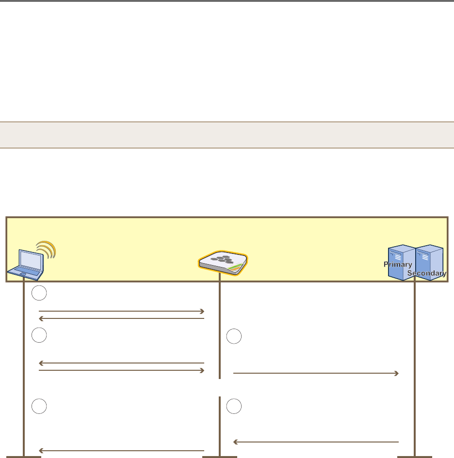
Deployment Guide 123
EXAMPLE 7: DEFINING AAA RADIUS SETTINGS
EXAMPLE 7: DEFINING AAA RADIUS SETTINGS
In this example, you define the connection settings for a RADIUS server so that HiveAPs can send RADIUS
authentication requests to the proper destination.
After corporate employees associate with HiveAPs, they gain network access by authenticating themselves to a
RADIUS server. The authentication process makes use of the IEEE 802.1X standard. Within this context, wireless
clients act as supplicants, HiveAPs as authenticators, and the RADIUS server as the authentication server. The roles
of each participant, packet exchanges, and connection details for the RADIUS server are shown in Figure 16.
Figure 16 IEEE 802.1X Authentication Process
1. Click Configuration > Authentication > AAA Client Settings > New > General, and then enter the following:
•RADIUS Name: RADIUS-Servers (You cannot use spaces in the RADIUS profile name.)
• Retry Interval: 1800 (Seconds)
Enter the period of time that a HiveAP waits before retrying a previously unresponsive primary RADIUS
server. If a primary RADIUS server does not respond to three consecutive attempts—where each attempt
consists of ten authentication requests sent every three seconds (30 seconds for a complete request)—and a
backup RADIUS server has been configured, the HiveAP sends further authentication requests to the backup
server. The default is 600 seconds (or 10 minutes). The minimum is 60 seconds and the maximum is
Note: You can define a HiveAP as a RADIUS server. A HiveAP RADIUS server only supports 802.1X authentication,
so you cannot use it to authenticate users through a captive web portal.
A supplicant (wireless client) makes an
association with an authenticator (HiveAP).
The authenticator checks the RADIUS code
indicating whether the supplicant is accepted
or rejected. (It also checks for attributes
indicating the user group for the supplicant).
The supplicant checks the EAP message.
The authenticator and supplicant exchange
EAP-Request/Identity and EAP-Response/
Identity messages.
Supplicant
(Wireless Client) Authenticator
(HiveAP) Authentication Servers
(RADIUS Servers)
1
2
The authentication server replies with either
a RADIUS Access-Accept or Access-Reject
message containing an EAP-Success or
EAP-Failure message.
The authenticator sends the EAP-Response/
Identity message as one or more attributes in
a RADIUS Access-Request message to the IP
address of the RADIUS authentication server.
3
4
5
. . . Depending on the authentication method—TLS, TTLS, PEAP—more exchanges might take place here . . .
Primary RADIUS Server
IP address: 10.1.1.15
Shared secret: J7ix2bbbLA
Authentication port: 1812
Server priority: First
Secondary RADIUS Server
IP address: 10.1.2.16
Shared secret: J8Dx2c13Mb
Authentication port: 1812
Server Priority: Second
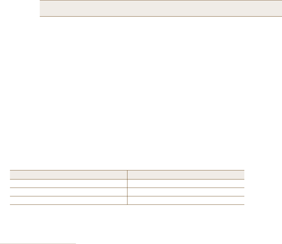
Chapter 8 HiveManager Configuration Examples
124 Aerohive
100,000,000 seconds. Generally, you want to make the retry interval fairly large so that supplicants (that is,
wireless clients requesting 802.1X authentication) do not have to wait unnecessarily as a HiveAP repeatedly
tries to connect to a primary server that is down for an extended length of time.
• Accounting Interim Update Interval: 20 (default)
This is the interval in seconds for updating the RADIUS accounting server with the cumulative length of a
client’s session. Because this example does not make use of RADIUS accounting, leave the default setting.
•Description: 802.1X authentication for corp employees
2. Click the RADIUS Servers tab, enter the following, and then click Apply:
—Type: IP Address
— Server IP/Name: RADIUS-Server-Primary (previously configured in "RADIUS Servers" on page 102)
—Shared Secret: J7ix2bbbLA
—Confirm Secret: J7ix2bbbLA
— Authentication Port: 1812 (default RADIUS authentication port number)
— Enable Accounting: (clear)
— Server Priority: Primary
—Description: Primary RADIUS server
•Click New, enter the following, and then click Apply:
—Type: IP Address
— Server IP/Name: RADIUS-Server-Secondary (previously configured in "RADIUS Servers" on page 102)
—Shared Secret: J8Dx2c13Mb
—Confirm Secret: J8Dx2c13Mb
— Authentication Port: 1812 (default RADIUS authentication port number)
— Enable Accounting: (clear)
— Server Priority: Backup1
—Description: Backup (Secondary) RADIUS server
3. To save the configuration and close the dialog box, click Save.
RADIUS Server Attributes
On the two RADIUS servers (also referred to as "RADIUS home servers"), define the HiveAPs as RADIUS clients.3 Also,
configure the following attributes for the realms to which user accounts matching the two user profiles belong:
The RADIUS server returns one of the above sets of attributes based on the realm to which an authenticating user
belongs. HiveAPs then use the combination of returned RADIUS attributes to assign users to profile 3 ("IT"), or 4
("Emp"). Note that these attributes do not create a GRE tunnel, which the tunnel type might seem to indicate.
Note: The shared secret is a case-sensitive alphanumeric string that must be entered on the
RADIUS authentication server exactly as shown above.
3. If you use RADIUS proxy servers, then direct RADIUS traffic from the HiveAPs to them instead of the RADIUS home servers. This
approach offers the advantage that you only need to define the proxy servers as clients on the RADIUS home servers. You can
then add and remove multiple HiveAPs without having to reconfigure the RADIUS home servers after each change.
Realm for IT (User Profile Attribute = 3) Realm for Emp (User Profile Attribute = 4)
Tunnel Type = GRE (value = 10) Tunnel Type = GRE (value = 10)
Tunnel Medium Type = IP (value = 1) Tunnel Medium Type = IP (value = 1)
Tunnel Private Group ID = 3 Tunnel Private Group ID = 4

Deployment Guide 125
EXAMPLE 8: CREATING HIVES
EXAMPLE 8: CREATING HIVES
A hive is a set of HiveAPs that exchange information with each other to form a collaborative whole. In this example,
you define three hives: two for the two buildings at headquarters and a third for the branch site. Later, in "Example
9: Creating WLAN Policies" on page 126, you assign the hives to WLAN policies, which in turn, you assign to HiveAP
devices in "Example 10: Assigning Configurations to HiveAPs" on page 135.
Hive1
Click Configuration > Hives > New > General, enter the following, leave the other options at their default
settings, and then click Save:
•Hive: Hive1 (You cannot use spaces in the name of a hive.)
• Description: Enter a meaningful comment, such as "Hive for HQ, Bldg 1"
• Modify Encryption Protection: (select); g3r4oU7a#x
The password string is what hive members use when authenticating themselves to each other over the
wireless backhaul link using WPA-PSK CCMP (AES). It can be from 8 to 63 characters long and contain special
characters. If you do not enter a password string, HiveManager derives a default password from the hive
name.
Hive2
Click Configuration > Hives > (check box) Hive1 > Clone > General, change the following, leave the other
options at their previously defined settings, and then click Save:
•Hive: Hive2
• Description: Modify the description for Hive2 to something appropriate, such as "Hive for HQ, Bldg 2".
• Modify Encryption Protection: (select); wWaG8U!3#2
Hive3
Click Configuration > Hives > (check box) Hive2 > Clone > General, change the following, leave the other
options at their previously defined settings, and then click Save:
•Hive: Hive3
• Description: Modify the description for Hive3 to something appropriate, such as "Hive for branch site".
• Modify Encryption Protection: (select); C!8vGg5Jo3
Note:
A WLAN policy is different from a hive. Whereas the members of a WLAN policy share a set of policy-based
configurations, the members of a hive communicate with each other and coordinate their activities as access
points. WLAN policy members share configurations. Hive members work together collaboratively.
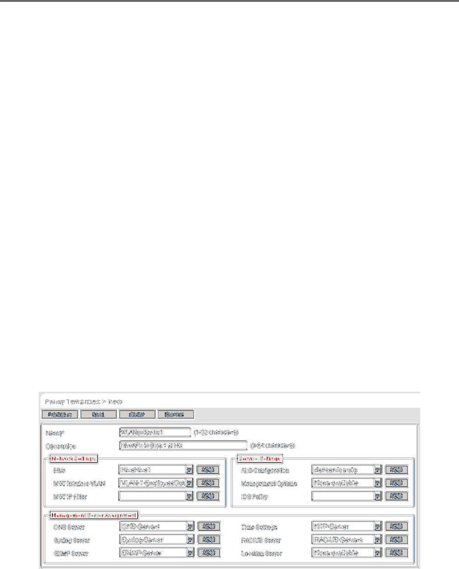
Chapter 8 HiveManager Configuration Examples
126 Aerohive
EXAMPLE 9: CREATING WLAN POLICIES
Through HiveManager, you can configure two broad types of features:
• Policy-based features – In combination, these features form policies that control how users access the network:
SSIDs, user profiles, QoS (Quality of Service) forwarding mechanisms and rates, hives, AAA (authentication,
authorization, accounting) services, management services (DNS, NTP, syslog), mobility policies, IP and MAC
firewall policies, and VLAN assignments.
• Connectivity-based features – These features control how hive members communicate with the network and
how radios operate at different modes, frequencies, and signal strengths.
A WLAN policy is an assembly of policy-based configurations that HiveManager pushes to all HiveAPs that you assign
to the policy. Because these configurations are policy-based, they can apply across multiple physical devices. In
contrast, connectivity-based configurations are more appropriately applied to smaller sets of devices or to
individual devices themselves.
In this example, you create "WLANpolicy-hq1" and "WLANpolicy-hq2" for the two buildings at corporate headquarters
and "WLANpolicy-branch1" for the branch site. You add a hive, management server assignments, SSID profile–radio
mode–user profile mappings, plus the QoS settings for each user group.
WLANpolicy-hq1
This WLAN policy is for all the HiveAPs in Building 1 at the corporate headquarters depicted in Figure 1 on page 89.
The New WLAN Policy dialog box consists of several pages. The configuration of the items on each page is presented
individually and in detail. The other WLAN policies are clones of this one with only minor changes.
WLANpolicy-hq1 (Page 1)
On the first page of the new WLAN policy dialog box, you define the name and a description of the WLAN policy, and
set network settings, service settings, and management server assignments for the HiveAPs to which you will apply
this WLAN policy. See Figure 17.
Figure 17 First Page of the WLAN Policy Dialog Box
Deployment Guide 127
EXAMPLE 9: CREATING WLAN POLICIES
1. Click Configuration > WLAN Policies > New, enter the following on the first page of the new WLAN policy
dialog box:
• Name: WLANpolicy-1 (You cannot use spaces in the WLAN policy name.)
• Description: Enter a useful description, such as "HiveAPs in Bldg1 at HQ".
Network Settings
2. Enter the following in the Network Settings section. (Note that the hive and VLAN were previously
configured in "Example 8: Creating Hives" on page 125 and "Defining VLANs" on page 100.)
•Hive: Hive1
•MGT Interface VLAN: 1 (or VLAN-1-EmployeeData)
In this example, the MGT interface is in VLAN 1, the same VLAN as that for employee data traffic. You
can specify either the predefined VLAN "1" or "VLAN-1-EmployeeData", which was previously created.
• MGT IP Filter: leave empty. A management IP address filter defines addresses from which admins are
permitted administrative access to HiveAPs. This filter was not configured in the preceding examples.
Service Settings
3. Leave the Service Settings fields at their default values or empty. None of these options were modified or
configured in the preceding examples.
Management Server Assignment
4. Enter the following in the Management Server Assignment section. (Note that the following settings were
previously configured in "Example 6: Setting Management Service Parameters" on page 120 and "Example 7:
Defining AAA RADIUS Settings" on page 123.)
•DNS Server: DNS-Servers
• Syslog Server: Syslog-Server
•SNMP Server: SNMP-Server
• Time Settings: NTP-Server
• RADIUS Server: RADIUS-Servers
• Location Server: None available (this option was not configured in the preceding examples)
5. To proceed to the next page, click Next.
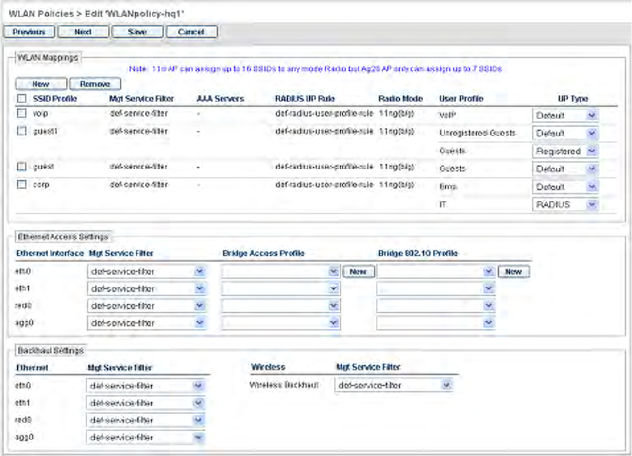
Chapter 8 HiveManager Configuration Examples
128 Aerohive
WLANpolicy-hq1 (Page 2)
On the second page of the new WLAN policy dialog box, you can map SSIDs to management service filters, AAA
servers, radio modes, and user profiles. In addition, you can set the Ethernet interface in access mode
(Bridge-Access or Bridge-802.1Q) and assign management service filters to the Ethernet and wireless backhaul
interfaces. (Note that because no management service filters were set in the previous examples, you only configure
WLAN mappings below.) See Figure 18.
Figure 18 Second Page of the WLAN Policy Dialog Box
WLAN Mappings
Configure the WLAN mappings of SSIDs to radio modes and user profiles. (The SSIDs were previously configured
in "Example 5: Setting SSIDs" on page 117, and the user profiles were configured in "Example 4: Creating User
Profiles" on page 113.)
SSID: voip
1. Enter the following to define the WLAN mappings for the voip SSID, and then click Apply:
• SSID Profile: voip
•MGT Service Filter: def-service-filter (default)
• AAA Servers: (leave empty; this setting is for overriding the RADIUS server setting on the previous page
of this dialog box, and, in any case, is not applicable to SSIDs using preshared keys)
Deployment Guide 129
EXAMPLE 9: CREATING WLAN POLICIES
•RADIUS UP Rule: def-radius-user-profile-rule (default)
This setting essentially controls which users authenticated by a RADIUS server can access the SSID.
Because the voip SSID does not use RADIUS authentication, the setting is not applicable.
•Radio Mode: 11ng(b/g)
In this example, you want to use IEEE 802.11b/g for network access traffic because a broader range of
wireless clients support IEEE 802.11b than IEEE 802.11a, which came out two years later (despite its
alphabetical precedence), and it provides slightly greater coverage.
The three choices in the Radio Mode drop-down list are as follows:
11na+11ng(a+b/g): This binds the SSID to two subinterfaces, each linked to a different radio
operating in separate frequency bands. Radio 1 supports IEEE 802.11b/g and operates in the 2.4
GHz band, and radio 2 supports IEEE 802.11a and operates in the 5 GHz band.
This is a good approach if the HiveAPs need to interoperate with some wireless clients that only
support 802.11b/g and others that only support 802.11a. In this case, both of the wifi
interfaces—wifi0 and wifi1—must be in access mode. On the other hand, if hive members need to
support wireless backhaul communications, then you cannot take this approach because one
interface (wifi1 by default) will need to be in backhaul mode and its subinterfaces (wifi1.1 –
wifi1.4), therefore, cannot support an SSID.
11ng(b/g): This binds the SSID to a subinterface linked to a radio operating at 2.4 GHz for the IEEE
802.11b or IEEE 802.11g standards.
11na(a): This binds the SSID to a subinterface using an antenna operating at 5 GHz for the IEEE
802.11a standard.
•User Profile: VoIP
2. After you click Apply, a drop-down list appears for the user profile type. Choose Default.
SSID: corp
1. Click New, enter the following to define the WLAN mappings for the corp SSID, and then click Apply:
• SSID Profile: corp
•MGT Service Filter: def-service-filter (default)
• AAA Servers: (leave empty; you want to use the RADIUS servers set on the previous page)
•RADIUS UP Rule: def-radius-user-profile-rule (default)
The default RADIUS user profile rule allows all users authenticated by the same RADIUS server to access
the SSID. In this example, only corporate employee accounts are stored on the RADIUS server, so there
is no need to restrict access to a smaller set of users.
•Radio Mode: 11ng(b/g)
•User Profile: IT and Emp (SHIFT-click or CTRL-click to make multiple selections.)
2. After you click Apply, a drop-down list appears for the user profile type. Choose RADIUS for IT, and choose
Default for Emp.
When authenticating users through 802.1X to a RADIUS server, there can be multiple user profiles, and the
RADIUS server will indicate which one the HiveAP applies to each user. However, if the RADIUS server does
not have a set of attributes configured for some users, then the HiveAP applies the user profile that you
mark as the default. One of the two user profile types must be marked as default and the other as RADIUS.
Chapter 8 HiveManager Configuration Examples
130 Aerohive
SSID: guest
1. Click New.
2. Depending on which guest access method you used (see "Example 3: Providing Guest Access" on page 104),
enter either of the following to define the WLAN mappings for the guest SSID, and then click Apply:
For guest access using a preshared key:
• SSID Profile: guest
•MGT Service Filter: def-service-filter (default)
• AAA Servers: (leave empty)
•RADIUS UP Rule: def-radius-user-profile-rule (default)
•Radio Mode: 11ng(b/g)
•User Profile: Guests
After you click Apply, choose Default as the user profile type.
or
For guest access using a captive web portal:
• SSID Profile: guest
•MGT Service Filter: def-service-filter (default)
• AAA Servers: (leave empty)
•RADIUS UP Rule: def-radius-user-profile-rule (default)
•Radio Mode: 11ng(b/g)
•User Profile: Guests and Unregistered-Guests
After you click Apply, choose Default as the user profile type for Unregistered-Guests. Choose Registered
as the user profile type for Guests.
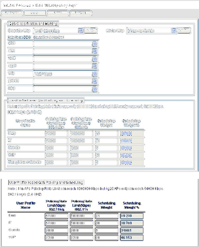
Deployment Guide 131
EXAMPLE 9: CREATING WLAN POLICIES
WLANpolicy-hq1 (Page 3)
On the third page of the new WLAN policy dialog box, you can assign QoS classifier and marker maps to SSIDs and
specify user profile-based QoS data forwarding rate limits and weights. (Note that no marker maps were configured
previously, so this option is unavailable.)
To view the third page of the WLAN policy dialog box configured with the SSID "guest" with and without a captive
web portal, see Figure 19.
Figure 19 Third Page of the WLAN Policy Dialog Box (SSID "guest" with and without a Captive Web Portal)
The User profile settings, maximum traffic forwarding rates per user profile, and the WRR (weighted round robin)
weights for each profile are shown in Figure 20 on page 132.
When the SSID "guest" does not
use a captive web portal, there is
only one user profile: "Guests"
When the SSID "guest" uses a
captive web portal, there are two
user profiles:
"Guests" (Registered)
"Unregistered-Guests" (Default)
You must set the same policing
rate limits and scheduling
weights for both of these profiles.
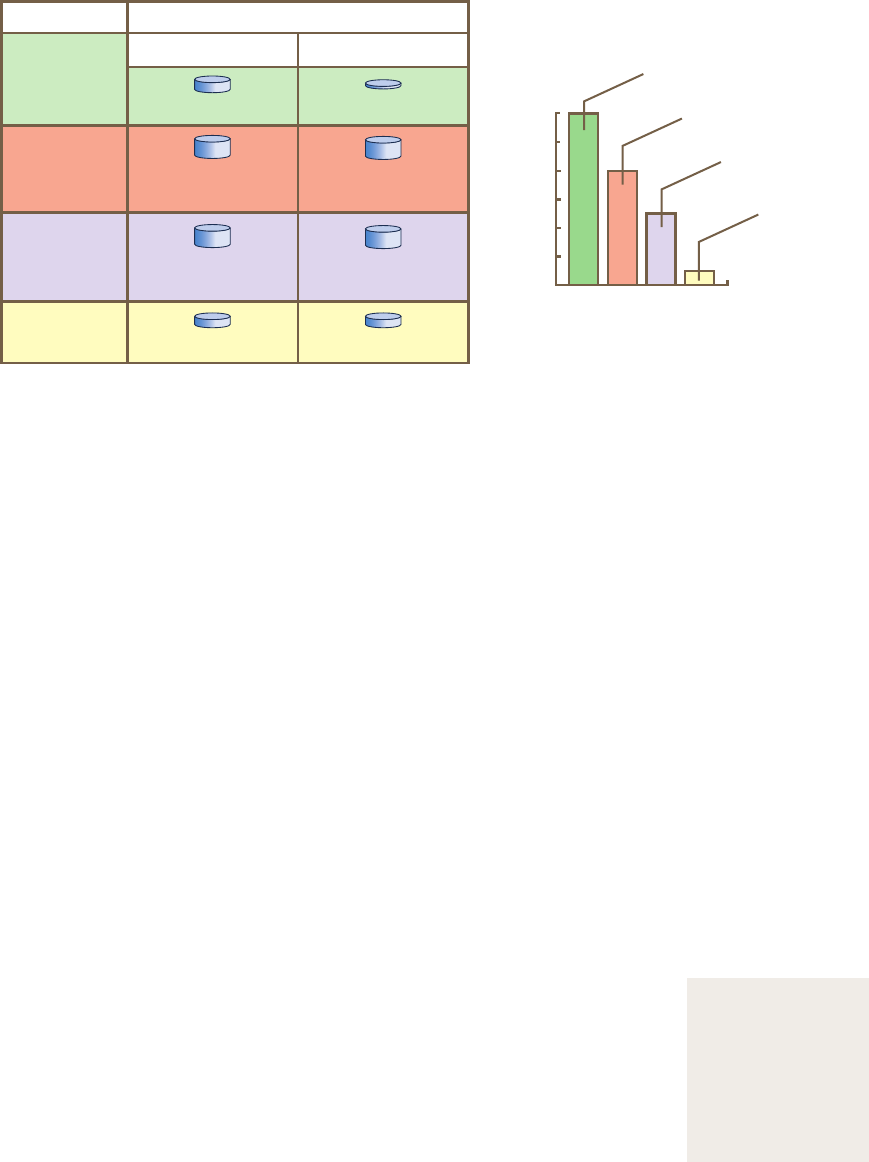
Chapter 8 HiveManager Configuration Examples
132 Aerohive
Figure 20 User Profiles, Forwarding Rates, and Weights
1. Enter the following in the QoS Classification and Marking section:
• Classifier Map: VoIP-Mapping
•voip: VoIP-QoS
The QoS map and policy were previously configured in "Mapping the MAC OUI and Services to Aerohive
Classes" on page 98, and as part of user profiles in "Example 4: Creating User Profiles" on page 113.
2. Enter the following in the User Profile Based QoS Policing and Scheduling section, and then click Save:
SSID "guests" without a captive web portal (only one user profile)
User Profile Name Policing Rate
Limit (Kbps)
802.11a/b/g
Policing Rate
Limit (Kbps)
802.11a/b/g
Scheduling Weight Scheduling Weight %
(read-only)
Guests 2000 2000 5 3.8461
VoIP 3200 3200 60 46.153
IT 54000 1000000 40 30.769
Emp 54000 1000000 25 19.230
User Profile Weights
(for traffic forwarding using WRR)
For IT, Emp, and Guests users, the maximum traffic forwarding
rates are the same for the entire user profile as they are for an
individual user. By keeping them the same, a single online user is
not restricted to a smaller rate than that of the profile to which he
or she belongs. (The individual user rate can be the same as or
smaller than its profile rate.)
For VoIP users, because individual calls use relatively little
bandwidth (8~64 Kbps), a single user does not need as much as
that for the entire VoIP user profile. A 3200 Kbps/profile maximum
allows up to 50 concurrent voice sessions at 64 Kbps per HiveAP
(3200 ÷ 64 = 50). If a stronger voice compression codex is used,
the number of concurrent voice sessions can increase
proportionately. The maximum user rate of 512 Kbps allows other
types of telephony-related traffic, such as DNS, DHCP, HTTP,
and TFTP, in addition to pure voice traffic.
0
10
20
30
40
50
60
Seconds
Weights
01
VoIP (60)
IT (40)
Guests (5)
Emp (25)
The bar chart indicates the ratio of allotted
bandwidth among the four user profiles based
on their respective weights. During the course
of one second, a HiveAP allots 12 times more
bandwidth for VoIP users, 8 times more for IT
users, and 5 times more for Emp users than it
allots for Guests.
Bandwidth rationing only occurs when usage is
at maximum capacity.
Note: Weights do not apply to strict traffic
forwarding.
Note: Unregistered-Guests (ID 6) is not shown.
User Profiles Maximum Traffic Forwarding Rates
Name: VoIP
ID: 2
Name: IT
ID: 3
Name: Emp
ID: 4
Name: Guests
ID: 5
Per Profile
11a/b/g/n 3200 Kbps 11a/b/g/n 512 Kbps
11a/b/g 54,000 Kbps
11n 1,000,000 Kbps
11a/b/g 54,000 Kbps
11n 1,000,000 Kbps
11a/b/g 54,000 Kbps
11n 1,000,000 Kbps
11a/b/g 54,000 Kbps
11n 1,000,000 Kbps
11a/b/g/n 2000 Kbps 11a/b/g/n 2000 Kbps
Per User

Deployment Guide 133
EXAMPLE 9: CREATING WLAN POLICIES
SSID "guests" with a captive web portal (two user profiles)
Some notes about the settings for each user profile:
Guests user profile
• Entire User Profile Rate Limit: 2000 Kbps
This is a limited amount of bandwidth that all users belonging to this profile can use. This setting
provides guests with a basic amount of available traffic.
• Entire User Profile Weight: 5
Because wireless access for guests is mainly a convenience and not a necessity, you assign it the lowest
weight to give it the lowest priority. The weight defines a preference for forwarding traffic. It does not
specify a percentage or an amount. Its value is relative to other weights. However, you can see an
automatically calculated percentage of this weight versus those of other user profiles in the far right
column.
VoIP user profile
• Entire User Profile Rate Limit: 3200 Kbps
This is the maximum amount of bandwidth that all users belonging to this profile can use. The typical
bandwidth consumption for VoIP is about 8 – 64 Kbps ,depending on the speech codec used. This setting
supports up to 50 concurrent VoIP sessions using 64-Kbps compression (3200 Kbps / 64 Kbps = 50
sessions).
• Entire User Profile Weight: 60
Because you want HiveAPs to favor VoIP traffic over all other types, you give this profile the highest
weight.
IT user profile
• Entire User Profile Rate Limit: 54000 Kbps for 802.11a/b/g and 1000000 for 802.11n (default)
This is the maximum amount of bandwidth that all users belonging to this profile can use. This setting
provides IT staff members with the maximum amount of available traffic.
• Entire User Profile Weight: 40
Because you want the HiveAPs to favor IT staff traffic over employee and guest traffic, you give this
profile a higher weight than those, but a lower one than that for VoIP traffic.
Emp user profile
• Entire User Profile Rate Limit: 54000 Kbps for 802.11a/b/g and 1000000 for 802.11n (default)
This is the maximum amount of bandwidth that all users belonging to this profile can use. This setting
provides employees with the maximum amount of available traffic.
• Entire User Profile Weight: 25
Because you want the HiveAPs to prioritize VoIP traffic first, IT staff traffic second, employee traffic
third, and guest traffic last, you give this profile a weight of 25. This weight is less than that for VoIP
traffic (60) and IT staff traffic (40), and more than what you are going to assign to guest traffic (5) next.
User Profile Name Policing Rate
Limit (Kbps)
802.11a/b/g
Policing Rate
Limit (Kbps)
802.11n
Scheduling Weight Scheduling Weight %
(read-only)
Guests 2000 2000 5 3.7037
Unregistered-Guests 2000 2000 5 3.7037
VoIP 3200 3200 60 44.444
IT 54000 1000000 40 29.629
Emp 54000 1000000 25 18.518
Chapter 8 HiveManager Configuration Examples
134 Aerohive
These weights skew the rate at which the HiveAPs forward queued traffic using the WRR (weighted
round robin) scheduling discipline. Roughly, for every 5 bytes of guest traffic per second, a HiveAP
forwards 25 bytes of employee traffic, 40 bytes of IT traffic, and 60 bytes of VoIP traffic. These
numbers are not exact because HiveAPs also have internal weights per class that also affect the amount
of traffic that a HiveAP forwards.
Unregistered-Guests profile
Although the Unregistered-Guests user profile is required for the configuration of the "guest" SSID using
a captive web portal, the HiveAP never applies the QoS settings for this user profile because it never
forwards traffic from unregistered guests.
WLANpolicy-hq2
This WLAN policy is for all the HiveAPs in Building 2 at the corporate headquarters depicted in Figure 1 on page 89.
Because this policy consists of nearly identical elements to those in WLANpolicy-hq1, you clone the first WLAN
policy and simply change the WLAN policy name and description, and the hive in the configuration.
Click Configuration > WLAN Policies > (check box) WLANpolicy-hq1 > Clone, change only the following, and
then click Save:
• Name: WLANpolicy-hq2
•Description: HiveAPs in Bldg 2 at HQ
•Hive: Hive2
WLANpolicy-branch1
This WLAN policy is for all the HiveAPs at the branch site depicted in Figure 1 on page 89. Because this policy
consists of nearly identical elements to those in WLANpolicy-hq1 and WLANpolicy-hq2, you can clone either policy
and simply change the WLAN policy name and description, and the hive in the configuration.
Click Configuration > WLAN Policies > (check box) WLANpolicy-hq2 > Clone, change only the following, and
then click Save:
• Name: WLANpolicy-branch1
•Description: HiveAPs at the branch site
•Hive: Hive3
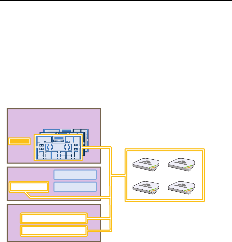
Deployment Guide 135
EXAMPLE 10: ASSIGNING CONFIGURATIONS TO HIVEAPS
EXAMPLE 10:ASSIGNING CONFIGURATIONS TO HIVEAPS
After completing the steps in the previous examples, you can now assign the following configurations as appropriate
to each HiveAP:
• WLAN policy (created in "Example 9: Creating WLAN Policies" on page 126)
• Radio profiles (default radio profiles)
• Map (uploaded in "Example 1: Mapping Locations and Installing HiveAPs" on page 91)
As the above list indicates, this example makes use of the two default radio profiles: radio_g0 for the wifi0
interface in access mode, and radio_a0 for the wifi1 interface in backhaul mode.
The HiveAP configuration assignments are presented conceptually in Figure 21.
Figure 21 HiveAP Configuration Assignments
In addition to assigning the above configurations to the HiveAPs, you also change their login settings (and country
code if necessary) and apply the classifier tags "hq" and "branch1" so that the HiveAPs at HQ and the branch site use
the correct DNS servers.
Finally, you update the HiveAPs with the new configuration settings—and captive web portal files, if a captive web
portal is a part of the configuration—to complete their deployment.
HQ-B1-F2
HQ-B1-F3
. . . . .. . .
. . . . .. . .
. . . . .. . .
Topology Maps
WLAN Policies WLANpolicy-hq2
WLANpolicy-branch1
Radio Profiles
HiveAPs on the First Floor of Building 1
WLANpolicy-hq1
radio_g0 – Access
radio_a0 – Backhaul
HQ-B1-F1
You assign particular combinations of configurations to sets of
HiveAPs.
For example, the four HiveAPs shown below were installed on
the first floor of building 1 at the corporate headquarters. You
know this because—during their installation—you either
configured their SNMP sysLocation MIB object to indicate the
map titled "HQ-B1-F1" or you wrote down the MAC addresses
and locations of all the HiveAPs you installed (see "Example 1:
Mapping Locations and Installing HiveAPs" on page 91).
Because you know where the HiveAPs are located, you assign
them to the HQ-B1-F1 map, WLANpolicy-hq1, classifier tag
"hq", and the two default radio profiles: radio_g0 for network
access and radio_a0 for wireless backhaul communications.
Chapter 8 HiveManager Configuration Examples
136 Aerohive
Assigning Configurations
1. Click Access Points > Automatically Discovered.
2. Select a group of HiveAPs associated with the same map.
If you defined SNMP sysLocation MIB objects as you installed the HiveAPs as explained in "Using SNMP" on
page 94, each HiveAP listed in the Automatically Discovered window will now include a map title in the
Topology Map column. By clicking the Topology Map column header, you can sort HiveAPs by topology map. You
can then select all the HiveAPs belonging to the same map (shift-click the check boxes to select multiple
contiguous HiveAPs) and assign the same WLAN policy, radio profiles, and classifier tags to them.
If you tracked HiveAPs by writing their MAC addresses on the maps as explained in "Using MAC Addresses" on
page 95, you can sort the HiveAPs in the Automatically Discovered window by MAC address. Click the Node ID
column header to display the HiveAPs numerically by MAC address. By referring to the MAC addresses and the
title of the map on which you wrote them during the installation, you can then select all the HiveAPs belonging
to the same map and assign the same map, WLAN policy, radio profiles, and classifier tags to them.
3. Click Modify > General, and then enter the following:
• WLAN Policy: Choose the WLAN policy that you want to assign to the selected HiveAPs. In these examples,
there are three WLAN policies. Assign WLANpolicy-hq1 to all HiveAPs in Building 1 at corporate
headquarters, WLANpolicy-hq2 to all HiveAPs in Building 2 at corporate headquarters, and
WLANpolicy-branch1 to all HiveAPs at the branch office.
• Topology Map: Choose the map that you want to assign to the selected HiveAPs. (If you used the SNMP
sysLocation MIB definition to associate HiveAPs with maps, HiveManager has automatically chosen the
correct map already.) The maps allow you to organize the HiveAPs by site (HQ or Branch1), then at HQ by
building (HQ-B1 or HQ-B2), and then by floor (HQ-B1-F1, HQ-B1-F2, HQ-B1-F3, and so on).
• Gateway Address: Leave as is.
• Location: If you set the SNMP sysLocation MIB when you installed the HiveAPs, leave this field as is. If not,
enter a description for the location of each HiveAP individually.
• Native VLAN: 1 (for control traffic among hive members on the wired backhaul interface)
• LAN Interface: Leave the settings as they are.
• WLAN Interface: Set the radio profile for wifi0 as radio_g0 and the radio profile for wifi1 as radio_a0.
Leave the values for the other fields as they are.
• HiveAP Classification: For HiveAPs at headquarters, type hq in the Tag1 field. For HiveAPs at the branch
site, type branch1 in the Tag1 field. By classifying the HiveAPs with these tags, they will receive the
similarly tagged IP address for the primary DNS server on the network at their respective locations. (The
two IP addresses are tagged in "DNS Servers" on page 101.)
4. Click Credentials, enter the following in the Root Admin Configuration section, and then click Save:
Root Admin Configuration
• New Admin Name: This is the root admin name that HiveManager uses to make SSH connections and
upload a full configuration to managed HiveAPs. The default root admin name and password is admin
and aerohive. To change the login settings on the HiveAPs, enter a new admin name. The admin name
can be any alphanumeric string from 3 to 20 characters long.
• New Password: Although the password is obscured, the default password is aerohive. To change the
default password on the HiveAPs, enter a new password here. The password can be any alphanumeric
string from 5 to 16 characters.
• Confirm New Password: If you entered a password in the above field, enter it again to confirm accuracy.

Deployment Guide 137
EXAMPLE 10: ASSIGNING CONFIGURATIONS TO HIVEAPS
DTLS Passphrase
HiveManager and HiveAPs use the DTLS (Datagram Transport Layer Security) passphrase to derive a
preshared key that they then use to mutually authenticate each other when making a CAPWAP connection.
By default, when a HiveAP first makes a CAPWAP connection to HiveManager, they use a predefined
bootstrap DTLS passphrase combined with several other values to derive a shared key that they then use to
authenticate each other. To change the DTLS passphrase, click Change Passphrase.
5. Repeat this procedure with the HiveAPs associated with all the other maps until they are all configured.
6. To accept all the HiveAPs for management through HiveManager, select the top check box to the left of "Host
Name" in the header in the Automatically Discovered window, and then click Accept.
HiveManager displays accepted HiveAPs in the Access Points > Managed HiveAPs window.
Updating the Country Code
When the preset region code for a managed HiveAP is "World", you must set the appropriate country code to control
the radio channel and power selections that that HiveAP can use. For HiveAPs intended for use in the United States,
the region code is preset as "FCC"—for "Federal Communications Commission"—and the country code is preset as
"United States".
If the region code for any of the managed HiveAPs is "World", set the country code as follows:
1. Click Access Points > Managed HiveAPs > (check box) hiveap > Update > Update Country Code.
2. In the Update Country Code dialog box , enter the following, and then click Upload:
• Select the check box for the HiveAPs whose country code you want to change.4
• Choose the country where they are deployed from the New Country Code list.
• In the Activate After field, set an interval after which the HiveAP reboots to activate the updated country
code settings.
HiveManager updates the country code on the selected HiveAPs. To put the radio settings for the updated
country code in effect, they reboot after the activation interval that you set elapses. After the HiveAPs reboot,
they then apply the appropriate radio settings for the newly updated country code.
Note: When you click Change Passphrase, HiveManager immediately generates a new, random passphrase.
You can override this by typing your own passphrase, which can be from 16 to 32 characters long.
4. When updating the country code on HiveAPs in a mesh environment, you do not want the rebooting of portals to interrupt the
data path between the HiveManager and mesh points before they can complete their update process. Therefore, try to update
and reboot mesh points first. Then, update and reboot the portals. See "Updating HiveAPs in a Mesh Environment" on page 88.
Note: Be sure to choose the correct country. An incorrect choice might result in illegal radio operation and
cause harmful interference to other systems.

Chapter 8 HiveManager Configuration Examples
138 Aerohive
Uploading HiveAP Configurations
At this point, you have assigned configurations to the HiveAPs, accepted them for management, changed their login
settings, and possibly the country code as well. Now, you can push their configurations from HiveManager to the
HiveAPs.
1. Click Access Points > Managed HiveAPs > Update > Upload and Activate Configuration (Wizard).
The Upload and Activate Configuration (Wizard) dialog box appears.
2. If you have an SSID using captive web portal files, the first step in the upload process is to upload these pages
and a server key, if the captive web portal uses HTTPS to secure guest registrations. To upload these files, select
the HiveAPs to which you want to send the files, and then click Upload.
The HiveAP Update Results page appears so that you can monitor the progress of the upload procedure.
3. After the files are successfully uploaded, click the Back button in your browser to return to the Upload and
Activate Configuration dialog box.
4. To continue to the next step, click Next.
5. There are two options for uploading configurations to HiveAPs:
• Complete Upload, which uploads the complete configuration to the managed HiveAPs and which requires
them to reboot to activate the new configuration
• Delta Upload, which uploads only the parts of the configuration that were not pushed to the managed
HiveAP in a previous configuration update
Uploading a delta configuration does not require activation by rebooting the HiveAP and is, therefore, less
disruptive. However, before HiveManager can upload a delta configuration to a managed HiveAP, it must first
upload the full configuration and activate it by rebooting the HiveAP. After that, you can upload delta
configurations. When initially sending the configuration to HiveAPs, you must choose Complete Upload.
Note: If a managed HiveAP already has the maximum number of captive web portal directories (8), you must
delete at least one of them before you can add a new one. To see how many directories are already on a
HiveAP and delete a directory if necessary, do the following:
1. Make an SSH connection to the managed HiveAP by finding an icon of the HiveAP on a map,
right-clicking the icon, and choosing SSH to HiveAP
2. Enter the following command to see the number of existing directories and their names:
show web-directory
3. Delete a directory by entering the following command, in which <string> is the name of the
directory that you want to delete: no web-directory <string>
Note: If there is any failure when performing a delta upload, the next upload must be a full upload.

Deployment Guide 139
EXAMPLE 10: ASSIGNING CONFIGURATIONS TO HIVEAPS
6. Select the HiveAPs whose configurations you want to update, select one of the following options for controlling
when the uploaded configurations are activated (by rebooting the HiveAPs), and then click OK:
•Activate at: Select this option and set the time when you want the updated HiveAPs to activate their
new configuration. This is a good choice if you want to stagger the activation, or if you want to load the
configuration now but activate it when the network is less busy. To use this option accurately, both
HiveManager and the managed HiveAPs need to have NTP enabled.
•Activate after: Select this option to load the configuration on the selected HiveAPs and activate it after
a specified interval. The range is 0 – 3600 seconds; that is, immediately to one hour. The default is 60
seconds.
•Activate at next reboot: Select this option to load the configuration and not activate it. The loaded
configuration is activated the next time the HiveAP reboots.
HiveManager pushes the configuration to all the selected HiveAPs. After they reboot to activate their new
configurations, they reconnect with HiveManager. To check the status of their CAPWAP connections, see the
Status and CAPWAP columns on the Access Points > Managed HiveAPs page. From this point, you can upload
delta configurations, which do not require the HiveAPs to reboot to activate a configuration update.
7. To check that the HiveAP is using the new files for its captive web portal, make an association with the HiveAP
using the guest SSID and then open a browser as described in step 2 to step 3 on page 109.
Note: When choosing which option to use, consider how HiveManager connects to the HiveAPs it is updating.
See "Updating HiveAPs in a Mesh Environment" on page 88.
Note: If you still see the default .html and .jpg files, try clearing your browser cache and then closing and
reopening the browser.
If you customize captive web portal pages and then later want to return to the default set of files,
enter this command: reset web-directory <string>
where <string> is the name of the directory whose contents you want to return to the default files.
Chapter 8 HiveManager Configuration Examples
140 Aerohive
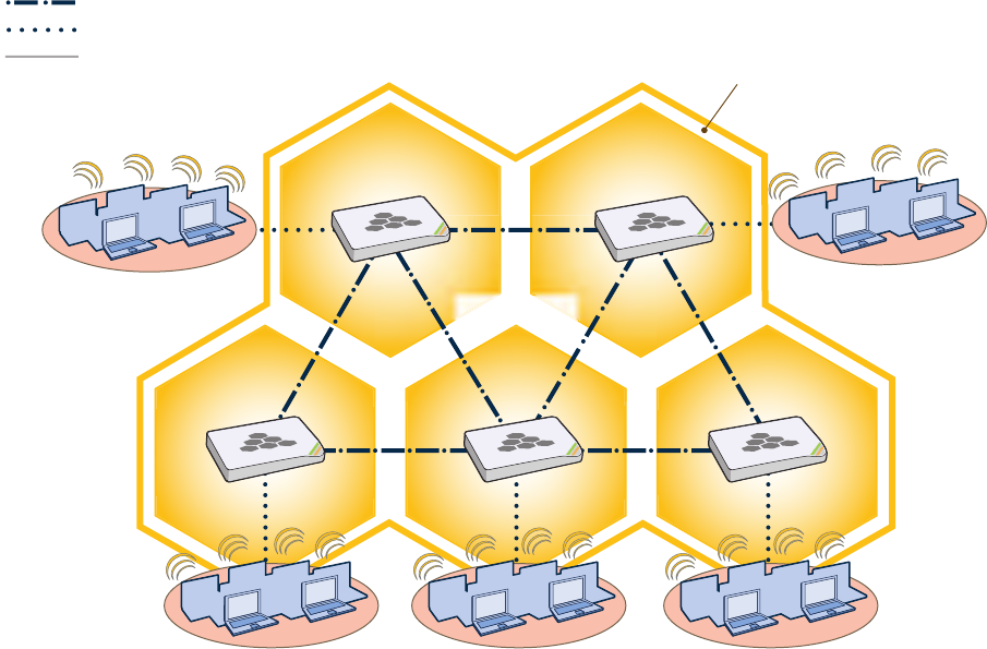
Deployment Guide 141
Chapter 9 HiveOS
You can deploy a single HiveAP and it will provide wireless access as an autonomous AP (access point). However, if
you deploy two or more HiveAPs in a hive, you can provide superior wireless access with many benefits. A hive is a
set of HiveAPs that exchange information with each other to form a collaborative whole (see Figure 1). Through
coordinated actions based on shared information, hive members can provide the following services that autonomous
APs cannot:
• Consistent QoS (quality of service) policy enforcement across all hive members
• Coordinated and predictive wireless access control that provides fast roaming to clients moving from one hive
member to another
• Best-path routing for optimized data forwarding
• Automatic radio frequency and power selection
Figure 1 HiveAPs in a Hive
Hive Members
Wired or Wireless Hive Communications (Backhaul)
Wireless Network Access Connections
Wired Ethernet Network Connections
Not shown: Switches for wired backhaul
connections and the portal link to the wired network.
Wireless Clients Wireless Clients
Wireless Clients
Hive
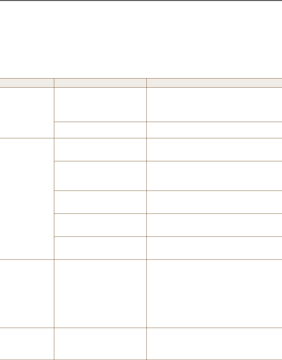
Chapter 9 HiveOS
142 Aerohive
COMMON DEFAULT SETTINGS AND COMMANDS
Many major components of HiveOS are automated and typically require no further configuration. For example, radio
power and frequency selection occurs automatically, as does route learning. Also, after defining a hive and its
security protocol suite, all HiveAPs belonging to that hive automatically initiate and maintain communications with
each other.
Additionally, there are many default settings that simplify the setup of a HiveAP because these are the typical
settings for many of the most common deployments. The following are some important default settings and the
commands necessary to change them if you need to do so:
Default Settings Commands
mgt0 interface DHCP client = enabled To disable the DHCP client:
no interface mgt0 dhcp client
To set an IP address:
interface mgt0 ip ip_addr netmask
VLAN ID = 1 To set a different VLAN ID:
interface mgt0 vlan number
wifi0 and wifi1
interfaces wifi0 mode = access
wifi1 mode = backhaul To change the mode of the wifi0 or wifi1 interface:
interface { wifi0 | wifi1 } mode { access
| backhaul }
wifi0 radio profile = radio_g0
wifi1 radio profile = radio_a0 To change the radio profile of the wifi0 or wifi1
interface to a different, previously defined profile:
interface { wifi0 | wifi1 } radio profile
string
antenna = internal To have the wifi0 interface use an external antenna:
interface { wifi0 | wifi1 } radio antenna
external
channel = automatic selection To set a specific radio channel:
interface { wifi0 | wifi1 } radio channel
number
power = automatic selection To set a specific transmission power level (in dBms):
interface { wifi0 | wifi1 } radio power
number
Default QoS policy def-user-qos policy:
user profile rate = 54,000 Kbps
user profile weight = 10
user rate limit = 54,000 Kbps
mode = weighted round robin for
Aerohive classes 0 - 5; strict
forwarding for classes 6 - 7
classes 0 - 4 rate limit = 54,000 Kbps
class 5 rate limit = 10,000 Kbps
classes 6 - 7 rate limit = 512 Kbps
To change the default QoS policy:
qos policy def-user-qos qos ah_class
{strict rate_limit 0 | wrr
rate_limit weight }
qos policy def-user-policy user-profile
rate_limit weight
qos policy def-user-policy user
rate_limit
User profile default-profile:
group ID = 0
policy name = def-user-qos
VLAN ID = 1
You cannot change the group ID or QoS policy name
for the default user profile. To change its VLAN ID:
user-profile default-profile vlan-id
number

Deployment Guide 143
CONFIGURATION OVERVIEW
CONFIGURATION OVERVIEW
The amount of configuration depends on the complexity of your deployment. As you can see in "Deployment
Examples (CLI)" on page 149, you can enter a minimum of three commands to deploy a single HiveAP, and just a few
more to deploy a hive.
However, for cases when you need to fine tune access control for more complex environments, HiveOS offers a rich
set of CLI commands. The configuration of HiveAPs falls into two main areas: "Device-Level Configurations" and
"Policy-Level Configurations" on page 144. Consider your deployment plans and then refer to the following sections
for guidance on the commands you need to configure them.
Device-Level Configurations
Device-level configurations refer to the management of a HiveAP and its connectivity to wireless clients, the wired
network, and other hive members. The following list contains some key areas of device-level configurations and
relevant commands.
• Management
• Administrators, admin authentication method, login parameters, and admin privileges
admin { auth | manager-ip | min-password-length | read-only | read-write |
root-admin } …
• Logging settings
log { buffered | console | debug | facility | flash | server | trap } …
• Connectivity settings
•Interfaces
interface { eth0 | wifi0 | wifi1 } …
• Layer 2 and layer 3 forwarding routes
route mac_addr …
ip route { default | host | net } ip_addr …
• VLAN assignments
For users:
user-profile string qos-policy string vlan-id number attribute number
For hive communications:
hive string native-vlan number
For the mgt0 interface:
interface mgt0 vlan number
• Radio settings
radio profile string …
Note: To find all commands using a particular character or string of characters, you can do a search using the
following command: show cmds | { include | exclude } string
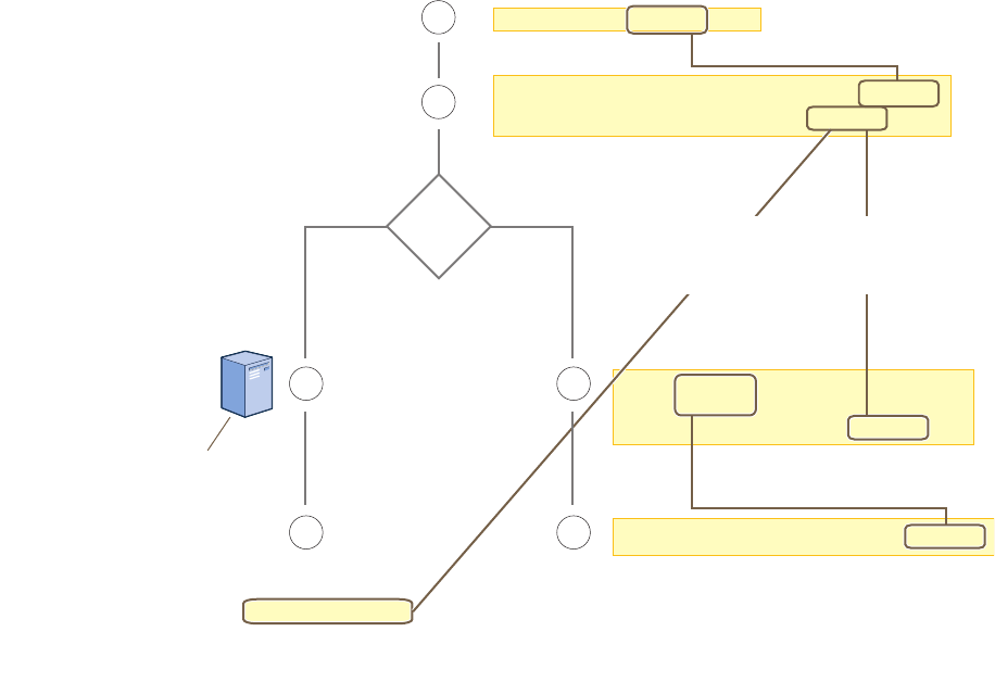
Chapter 9 HiveOS
144 Aerohive
Policy-Level Configurations
Policies control how wireless clients access the network. The following list contains some key areas of policy-level
configurations and relevant commands.
•QoS settings
qos { classifier-map | classifier-profile | marker-map | marker-profile |
policy } …
•User profiles
user-profile string …
• SSIDs
ssid string …
• AAA (authentication, authorization, and accounting) settings for IEEE 802.1X authentication
aaa radius-server …
While the configuration of most HiveOS features involves one or more related commands, to define and apply a QoS
policy to a group of users, you must configure several different but related features: a QoS policy, a user profile,
and—if you do not authenticate users with a RADIUS server—an SSID that references the user profile, and a
subinterface to which you assign the SSID. The configuration steps are shown in Figure 2.
Figure 2 Steps for Configuring and Applying QoS
user-profile string qos-policy string
vlan-id number attribute number
2
3
1
44
User accounts are stored
on the RADIUS Server.
Returned Attributes
• Tunnel Type = GRE (value = 10)
• Tunnel Medium Type = IPv4 (value = 1)
• Tunnel Private Group ID = user_profile_number
First, configure a QoS policy that you want to apply
to wireless traffic from a group of users.
The HiveAP applies the QoS policy to all
wireless clients that associate with the SSID.
ssid string
ssid string default-
user-profile-attr number
3
The attributes indicate which user profile to apply to the user,
and the profile in turn indicates which QoS policy to apply.
If you use a RADIUS server, configure
it to return attributes for the realm to
which the wireless users belong. After
authenticating a user, the server
returns these attributes with the
Access-Accept message. The
attributes indicate which
user profile to apply to the
user, and the profile in turn
indicates the QoS policy to
apply.
qos policy string ...
interface interface ssid string
Second, configure a user profile that references the
QoS policy you just configured.
Assign the SSID to an interface.
RADIUS
Server?
NoYes
The next step depends on whether you use
a RADIUS server to authenticate users.
If you do not use a RADIUS server, create
an SSID that specifies the user profile
attribute as its default user profile.
Deployment Guide 145
HIVEOS CONFIGURATION FILE TYPES
HIVEOS CONFIGURATION FILE TYPES
HiveOS supports several types of configuration files: running, current, backup, bootstrap, default, and failed.
The running configuration (config) is the configuration that is actively running in DRAM. During the bootup process,
a HiveAP loads the running config from one of up to four config files stored in flash memory:
•current: a flash file containing a combination of default and admin-defined settings. During the bootup process,
this is the first config that the HiveAP attempts to load as the running config. This is also the file to which you
typically save commands from the running config (you can also save them to the bootstrap config). See Figure 3.
•backup: a flash file that the HiveAP attempts to load during the reboot process if there is a newly uploaded
current config file or if it cannot load the current config file. See Figure 4 on page 146 and Figure 5 on
page 146.
•bootstrap: a flash file containing a second config composed of a combination of default and admin-defined
settings. The HiveAP fails over to this config when you enter the reset config command or if both the
current and backup config files fail to load. See Figure 6 on page 148.
•default: a flash file containing only default settings. If there is no bootstrap config, the HiveAP reverts to this
config when you enter the reset config command or if both the current and backup config files fail to load.
See Figure 6 on page 148.
When using the CLI, the two most frequently accessed config types are the running config and current config. When
you enter a command in the running config, the HiveAP performs it immediately. However, because the running
config is stored in volatile memory (DRAM), the commands are not yet permanent and will be lost when the HiveAP
next reboots. For your configuration settings to persist after rebooting, enter the save config command. This
command saves the running config to the current config, which is a file stored in nonvolatile (flash) memory. See
Figure 3.
Figure 3 Relationship between Running and Current Config Files
Note: There is also a failed config file, which holds any backup config that fails to load. See Figure 5 on
page 146.
(Note: The commands in bold bold have not yet been saved,
which is why they do not appear in the current config.)
Current Config
(in flash memory)
Running Config
(in DRAM)
The running config comprises the current config
plus any commands that have not yet been
saved. The running config runs in DRAM.
The current config comprises saved
commands plus default settings. The
current config is stored in flash memory.
Running Config New Current Config
Previous Current Config
(overwritten)
When you enter the save config save config command,
the HiveAP saves the running config from
DRAM to flash memory, where it becomes
the new current config, replacing the one
previously there.
save config
(Note: After entering the save save
configconfig command, the current and
running configs become identical.)
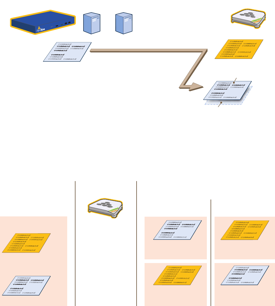
Chapter 9 HiveOS
146 Aerohive
When you upload a configuration file from HiveManager or from a TFTP or SCP server, the HiveAP stores the
uploaded file in the backup config partition in flash memory, where it remains until the HiveAP reboots. If there is a
backup config file already stored in flash, the newly uploaded file overwrites it. See Figure 4.
Figure 4 Relationship between Current and Backup Config Files during a File Upload
When the HiveAP reboots, it attempts to load the the newly uploaded config file. If the file loads successfully, the
HiveAP makes that file the new current config and makes the previous current config the new backup config. If the
file does not load successfully, the HiveAP reboots again and loads the previous current config file. The HiveAP saves
the file it was unable to load as a failed config for diagnostics. See Figure 5.
Figure 5 Relationship between Current and Backup Config Files while Rebooting a HiveAP
Config File Current Config
When you upload a config file from HiveManager or a TFTP or
SCP server, the HiveAP saves the uploaded file as a backup
config. This file replaces any previous backup config file that
might have been there.
TFTP
Server
SCP
Server
HiveManager or or HiveAP
Previous Backup Config
(overwritten)
New Backup Config
(in flash memory)
Current Config
(existing config)
Backup Config
(newly uploaded config file)
After uploading a new config
file, the following two config
files are stored in flash
memory on the HiveAP:
When you reboot the HiveAP, it tries to load the backup
config. Either of the following two results can occur:
If the newly loaded config
file loads successfully, . . .
. . . it becomes the new
current config, and . . .
. . . the previous current
config becomes the new
backup config.
. . . the backup config is
saved as a failed config
(for diagnostic analysis).
. . . the HiveAP reboots
again, loads the previous
current config, and . . .
If the newly loaded config
file fails to load, . . .
Reboot the HiveAP
Deployment Guide 147
HIVEOS CONFIGURATION FILE TYPES
When a HiveAP ships from the factory, it is loaded with a default config file, which acts initially as the running and
current configs. If you enter and save any commands, the HiveAP then stores a separate config file as the current
config, combining the default settings with the commands you entered and saved. If you want to return to the
default settings, you can press the reset button (see "Reset Button" on page 25) or enter the reset config
command. A HiveAP might also return to the default config if both the current and backup configs fail to load,
which might happen if you update the HiveOS firmware to an image that cannot work with either config.
Reverting to the default config can be very useful, especially in the early stages when you are still learning about
HiveOS and are likely to be experimenting with different settings. However, retaining the ability of a HiveAP to
revert to its default settings after its deployment can present a problem if it is a mesh point in a hive. If the HiveAP
reverts to the default config, it will not be able to rejoin its hive. Consequently, it will not be able to get an IP
address through DHCP nor be able to communicate with HiveManager (assuming that you are managing it through
HiveManager). In this case, you would have to make a serial connection to the console port on the HiveAP and
reconfigure its hive settings through the CLI.
To avoid the above situation, you can use a bootstrap config. A bootstrap config is typically a small config file that
comes last in the boot order (current – backup – bootstrap) and that replaces the default config as the one a HiveAP
loads when you reset the configuration. See Figure 6 on page 148.
Note: To upload and activate a config file from HiveManager , see "Uploading HiveAP Configurations" on
page 138. To upload and activate a config file from a TFTP or SCP server using the CLI, use the following
commands:
save config tftp://ip_addr:filename current { hh:mm:ss | now | offset hh:mm:ss }
save config scp://username@ip_addr:filename current { hh:mm:ss | now | offset
hh:mm:ss }
Note: You can disable the ability of the reset button to reset the configuration by entering this command: no
reset-button reset-config-enable
Note: Be careful to remember the login name and password defined in the bootstrap config file. If they become
lost or forgotten, you must obtain a one-time login key from Aerohive technical support. To get the key,
you must already have had a support contract in place. The first one-time login key is free. After that,
there is a small handling fee for each additional key.
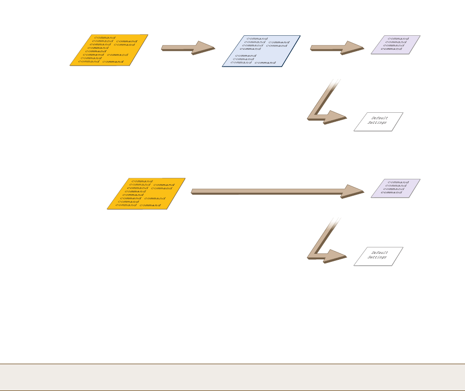
Chapter 9 HiveOS
148 Aerohive
Figure 6 Relationship of Current, Backup, Bootstrap, and Default Config Files
To create and load a bootstrap config, make a text file containing a set of commands that you want the HiveAP to
load as its bootstrap configuration (for an example, see "Loading a Bootstrap Configuration" on page 167). Save the
file locally and then load it with one of the following commands:
save config tftp://ip_addr:filename bootstrap
save config scp://username@ip_addr:filename bootstrap
After it is loaded, you can enter the following command to view the bootstrap file: show config bootstrap
If you want to run the bootstrap config, enter the following commands:
load config bootstrap
reboot
When the bootstrap config loads, enter the login parameters you defined for that configuration. To return to your
previous current config file, enter the following commands:
load config backup
reboot
Note: Similar to the way that a current config consists of the commands you added on top of the default config,
a bootstrap config consists of default definitions and settings plus whatever other settings you configure.
When you enter the reset config reset config command or press the
reset button on the front panel of the HiveAP device, the
HiveAP deletes the previous current config, reboots, and
loads the bootstrap config— if present—or the default config.
reset config
Current Config Bootstrap Config
Default Config
. . . or if there is no bootstrap config . . .
Resetting the Configuration
Current Config Backup Config Bootstrap Config
Default Config
. . . or if there is no bootstrap config . . .
If the HiveAP cannot load either the current or backup
config files, it deletes them, reboots, and loads the
bootstrap config— if present—or the default config.
Configuration Failover Behavior
Failover Failover

Deployment Guide 149
Chapter 10 Deployment Examples (CLI)
This chapter presents several deployment examples to introduce the primary tasks involved in configuring HiveAPs
through the HiveOS CLI.
In "Deploying a Single HiveAP" on page 150, you deploy one HiveAP as an autonomous access point. This is the
simplest configuration: you only need to enter and save three commands.
In "Deploying a Hive" on page 153, you add two more HiveAPs to the one deployed in the first example to form a hive
with three members. The user authentication method in this and the previous example is very simple: a preshared
key is defined and stored locally on each HiveAP and on each wireless client.
In "Using IEEE 802.1X Authentication" on page 158, you change the user authentication method. Taking advantage of
existing Microsoft AD (Active Directory) user accounts, the HiveAPs use IEEE 802.1X EAP (Extensible Authentication
Protocol) to forward authentication requests to a RADIUS server whose database is linked to that of the AD server.
In "Applying QoS" on page 161, you apply QoS (Quality of Service) filters to user traffic so that delay-sensitive voice
traffic receives higher priority than other more delay-resistant traffic.
In "Loading a Bootstrap Configuration" on page 167, you load a bootstrap config file on the HiveAPs. When a
bootstrap config is present, it loads instead of the default config whenever HiveOS is reset or if the current and
backup configs do not load. This example shows how using a bootstrap config can help minimize theft and increase
convenience.
Because each example builds on the previous one, it is recommended to read them sequentially. Doing so will help
build an understanding of the fundamentals involved in configuring HiveAPs.
If you want to view just the CLI commands used in the examples, see "CLI Commands for Examples" on page 170.
Having the commands in blocks by themselves makes it easy to copy-and-paste them at the command prompt.
The following are the equipment and network requirements for these examples:
•Equipment
• Management system (computer) capable of creating a serial connection to the HiveAP
• VT100 emulator on the management system
• Serial cable (also called a "null modem cable") that ships as an option with the HiveAP product. You use this
to connect your management system to the HiveAP.
•Network
• Layer 2 switch through which you connect the HiveAP to the wired network
• Ethernet cable—either straight-through or cross-over
• Network access to a DHCP server
• For the third and fourth examples, network access to an AD (Active Directory) server and RADIUS server
Note: To focus attention on the key concepts of an SSID (first example), hive (second example), and IEEE 802.1X
authentication (third example), QoS was intentionally omitted from these examples. However, the QoS
settings you define in the last example can apply equally well to the configurations in the others.
Note: You can also access the CLI by using Telnet or SSH (Secure Shell). After connecting a HiveAP to the
network, make either a Telnet or SSH connection to the IP address that the DHCP server assigns the
mgt0 interface.
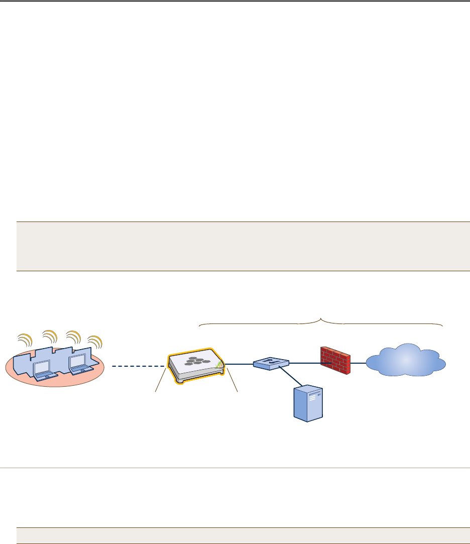
Chapter 10 Deployment Examples (CLI)
150 Aerohive
EXAMPLE 1: DEPLOYING A SINGLE HIVEAP
In this example, you deploy one HiveAP (HiveAP-1) to provide network access to a small office with 15 – 20 wireless
clients. You only need to define the following SSID (service set identifier) parameters on the HiveAP and clients:
•SSID name: employee
•Security protocol suite: WPA-auto-psk
• WPA – Uses Wi-Fi Protected Access, which provides dynamic key encryption and mutual authentication of
the client and HiveAP
• Auto – Automatically negotiates WPA or WPA2 and the encryption protocol: AES (Advanced Encryption
Standard) or TKIP (Temporal Key Integrity Protocol)
• PSK – Derives encryption keys from a preshared key that the client and HiveAP both already have
•Preshared key: N38bu7Adr0n3
After defining SSID "employee" on HiveAP-1, you then bind it to the wifi0 interface, which is in access mode by
default. The wifi0 interface operates at 2.4 GHz (in accordance with the IEEE 802.11b, g, and n standards). This
example assumes that the clients also support 802.11b, g, or n.
Figure 1 Single HiveAP for a Small Wireless Network
Step 1 Log in through the console port
1. Connect the power cable from the DC power connector on the HiveAP to the AC/DC power adaptor that ships
with the device as an option, and connect that to a 100 – 240-volt power source.
The Power LED glows steady amber during the bootup process. After the bootup process completes, it then
glows steady green to indicate that the firmware is loaded and running.
2. Connect one end of an RS-232 serial (or "null modem") cable to the serial port (or Com port) on your
management system.
Note: By default, the wifi1 interface is in backhaul mode and operates at 5 GHz to support IEEE 802.11a. To
put wifi1 in access mode so that both interfaces provide access—the wifi0 interface at 2.4 GHz and the
wifi1 interface at 5 GHz—enter this command: interface wifi1 mode access. Then, in addition
to binding SSID "employee" to wifi0 (as explained in step 2), also bind it to wifi1.
Note: If the switch supports PoE (Power over Ethernet), the HiveAP can receive its power that way instead.
Wireless Network-1
HiveAP-1 Switch Firewall
Internet
DHCP Server
Wireless clients associate
with HiveAP-1 using SSID
"employee" with the security
suite WPA-auto-psk
(PSK = N38bu7Adr0n3).
The wireless clients and the mgt0
interface on HiveAP-1 receive their
IP addresses and associated TCP/IP
settings from the DHCP server.
Wired Network
wifi0 interface
SSID "employee"
Access mode
IEEE 802.11b/g/n
Physical interface: eth0
Logical interface: mgt0
Backhaul mode
Network portal

Deployment Guide 151
EXAMPLE 1: DEPLOYING A SINGLE HIVEAP
3. Connect the other end of the cable to the male DB-9 or RJ-45 console port on the HiveAP.
4. On your management system, run a VT100 terminal emulation program, such as Tera Term Pro© (a free terminal
emulator) or Hilgraeve Hyperterminal® (provided with Windows® operating systems). Use the following settings:
• Bits per second (baud rate): 9600
• Data bits: 8
• Parity: none
•Stop bits: 1
• Flow control: none
For HiveAPs set with "FCC" as the region code, the Initial CLI Configuration Wizard appears. For HiveAPs set with
"world" as the region code, a prompt appears to set the country code for the location where you intend to
deploy the HiveAP. To set the country code, enter the boot-param country-code number command, in
which number is the appropriate country code number. For a list of country codes, see "Appendix A Country
Codes" on page 177.
5. Because you do not need to configure all the settings presented in the wizard, press N to cancel it.
The login prompt appears.
6. Log in using the default user name admin and password aerohive.
Step 2 Configure the HiveAP
1. Create an SSID and assign it to an interface.
ssid employee
ssid employee security protocol-suite wpa-auto-psk ascii-key N38bu7Adr0n3
You first create an SSID named "employee" and then define its protocol suite and preshared key
(N38bu7Adr0n3) in standard ASCII (American Standard Code for Information Interchange) text.
interface wifi0 ssid employee
You assign the SSID to the wifi0 interface, which is in access mode by default. When you make this
assignment, the HiveAP automatically creates subinterface wifi0.1 and uses that for the SSID. (A HiveAP
can create up to seven subinterfaces per interface—14 total.) A HiveAP uses one or two interfaces in
access mode to communicate with wireless clients accessing the network, and an interface in backhaul
mode to communicate wirelessly with other HiveAPs when in a hive (see subsequent examples).
2. (Optional) Change the name and password of the root admin.
admin root-admin mwebster password 3fF8ha
As a safety precaution, you change the default root admin name and password to mwebster and 3fF8ha.
The next time you log in, use these instead of the default definitions.
3. (Optional) Change the host name of the HiveAP.
hostname HiveAP-1
4. Save your changes to the currently running configuration, and then log out of the serial session.
save config
exit
The HiveAP configuration is complete.
Note: By default, the minimum password length is 5 characters. You can change the minimum length by
entering the following command: admin min-password-length <number> (The minimum
password length can be between 5 and 16 characters.)
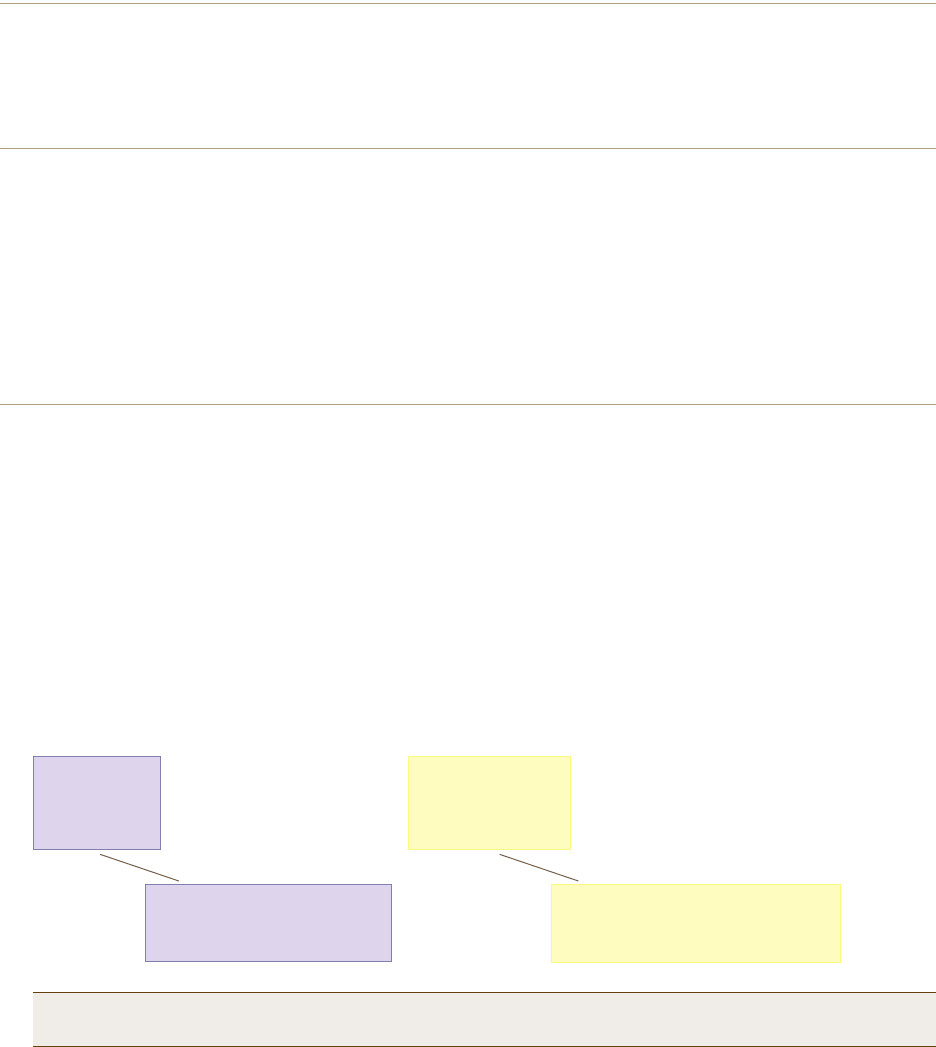
Chapter 10 Deployment Examples (CLI)
152 Aerohive
Step 3 Configure the wireless clients
Define the "employee" SSID on all the wireless clients. Specify WPA-PSK for network authentication, AES or TKIP
for data encryption, and the preshared key N38bu7Adr0n3.
Step 4 Position and power on the HiveAP
1. Place the HiveAP within range of the wireless clients and, optionally, mount it as explained in the mounting
section in the chapter about the HiveAP model that you are using.
2. Connect an Ethernet cable from the PoE In port to the network switch.
3. If you have powered off the HiveAP, power it back on by reconnecting it to a power source.
When you power on the HiveAP, the mgt0 interface, which connects to the wired network through the eth0 port,
automatically receives its IP address through DHCP (Dynamic Host Configuration Protocol).
Step 5 Check that clients can form associations and access the network
1. To check that a client can associate with the HiveAP and access the network, open a wireless client application
and connect to the "employee" SSID. Then contact a network resource, such as a web server.
2. Log in to the HiveAP CLI, and check that you can see the MAC address of the associated client and an indication
that the correct SSID is in use by entering the following command:
The setup of a single HiveAP is complete. Wireless clients can now associate with the HiveAP using SSID "employee"
and access the network.
Note: You can also enter the following commands to check the association status of a wireless client:
show auth, show roaming cache, and show roaming cache mac <mac_addr>.
Check that the MAC address
in the table matches that of
the wireless client .
Check that the authentication and
encryption modes match those in
the SSID security protocol suite.
show ssid employee station
Chan=channel number; Pow=Power in dbm;
A-Mode=Authentication mode; Cipher=Encryption mode;
A-Time=Associated time; Auth=Authenticated;
UPID=User profile Identifier; Phymode=Physical mode;
Mac Addr IP Addr Chan Rate Pow A-Mode Cipher A-Time VLAN Auth UPID Phymode
-------------- --------- ---- ---- ---- -------- ------- -------- ---- ---- ---- -------
0016:cf8c:57bc 10.1.1.35 11 54M -38 wpa2-psk aes ccm 00:00:56 1 Yes 0 11g
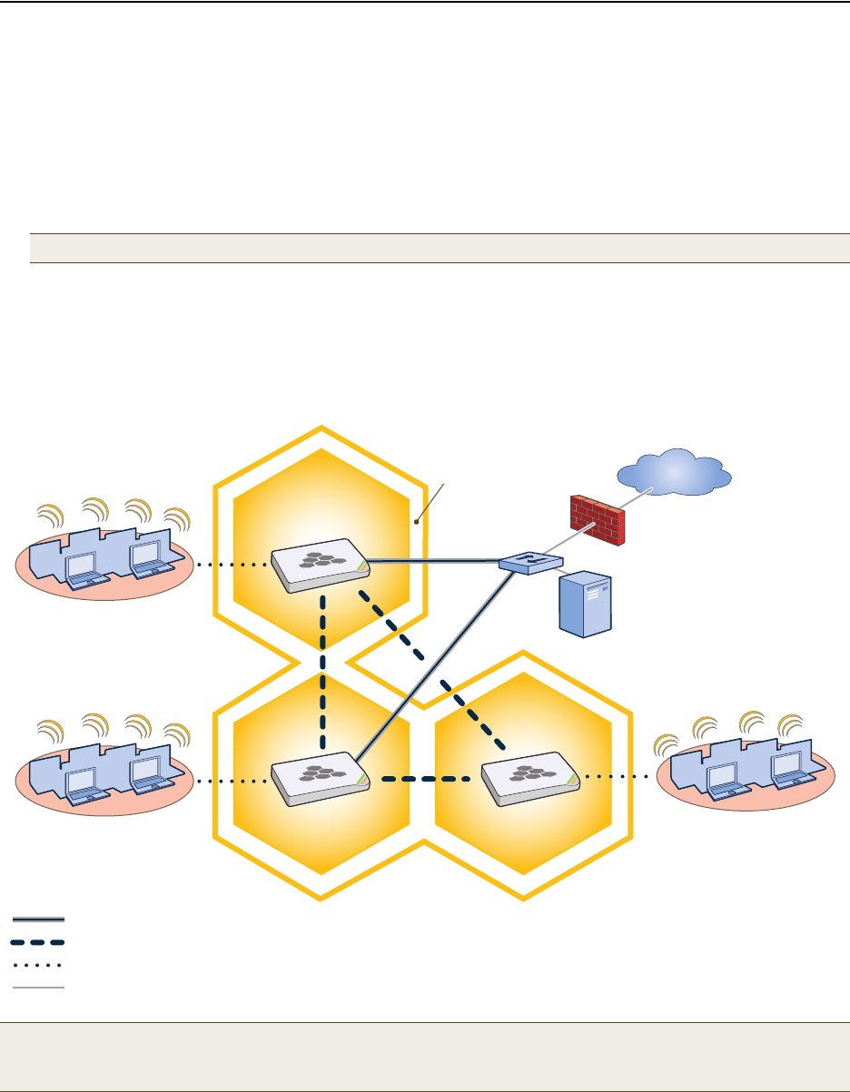
Deployment Guide 153
EXAMPLE 2: DEPLOYING A HIVE
EXAMPLE 2: DEPLOYING A HIVE
Building on "Deploying a Single HiveAP" on page 150, the office network has expanded and requires more HiveAPs to
provide greater coverage. In addition to the basic configuration covered in the previous example, you configure all
three HiveAPs to form a hive within the same layer 2 switched network. The following are the configuration details
for the hive:
•Hive name: hive1
•Preshared key for hive1 communications: s1r70ckH07m3s
HiveAP-1 and -2 are cabled to a switch and use the native ("untagged") VLAN for wired backhaul communications.
They communicate with each other over both wired and wireless backhaul links, the wired link taking precedence.
However, HiveAP-3 only communicates with HiveAP-1 and -2 over a wireless link (see Figure 2). Because HiveAP-1
and -2 connect to the wired network, they act as portals. In contrast, HiveAP-3 is a mesh point.
Figure 2 Three HiveAPs in a Hive
Note: The security protocol suite for hive communications is WPA-AES-psk.
Note: If all hive members can communicate over wired backhaul links, you can then use both radios for access.
The wifi0 interface is already in access mode by default. To put wifi1 in access mode, enter this command:
interface wifi1 mode access. In this example, however, a wireless backhaul link is required.
Wireless Network-1
Switch
Firewall
Internet
DHCP
Server
Wireless Network-2 Wireless Network-3
Wired Hive Backhaul Communications
HiveAP-1
(Portal)
HiveAP-2
(Portal) HiveAP-3
(Mesh Point)
Wireless Hive Backhaul Communications
Wireless Network Access Connections
HiveAP-1 and HiveAP-2 are portals and use both wired and
wireless backhaul methods to communicate with each other.
HiveAP-3 is a mesh point, using only a wireless connection for
backhaul communications with the other two hive members.
Wired Ethernet Network Connections
Hive1

Chapter 10 Deployment Examples (CLI)
154 Aerohive
Step 1 Configure HiveAP-1
1. Using the connection settings described in the first example, log in to HiveAP-1.
2. Configure HiveAP-1 as a member of "hive1" and set the security protocol suite.
hive hive1
You create a hive, which is a set of HiveAPs that collectively distribute data and coordinate activities
among themselves, such as client association data for fast roaming, route data for making optimal
data-path forwarding decisions, and policy enforcement for QoS (Quality of Service) and security.
hive hive1 password s1r70ckH07m3s
You define the password that hive members use to derive the preshared key for securing backhaul
communications with each other. The password must be the same on all hive members.
interface mgt0 hive hive1
By setting "hive1" on the mgt0 interface, you join HiveAP-1 to the hive.
save config
3. Before closing the console session, check the radio channel that HiveAP-1 uses on its backhaul interface, which
by default is wifi1:
HiveAP-1 is set to use wireless interface wifi1 and its subinterface wifi1.1 for backhaul communications.
Write down the radio channel for future reference (in this example, it is 149). When configuring
HiveAP-2 and -3, make sure that they also use this channel for backhaul communications.
exit
The wifi1 interface and the wifi1.1 subinterface are in backhaul mode and
are using channel 149. Both wifi1 and wifi1.1 use the default radio profile
radio_na0. (Depending on the HiveAP model, the default profile might be
radio_a0.) This is a profile for radio2, which operates in the 5 GHz
frequency range as specified in the IEEE 802.11a and n standards.
show interface
State=Operational state; Chan=Channel;
Radio=Radio profile; U=up; D=down;
Name MAC addr Mode State Chan VLAN Radio Hive SSID
------- -------------- -------- ----- ---- ---- -------- ----- --------
Mgt0 0019:7700:0020 - U - 1 - hive1 -
Eth0 0019:7700:0020 backhaul U - 1 - hive1 -
Wifi0 0019:7700:0024 access U 11 - radio_ng0 - -
Wifi0.1 0019:7700:0024 access U 11 - radio_ng0 hive1 employee
Wifi1 0019:7700:0028 backhaul U 149 - radio_na0 - -
Wifi1.1 0019:7700:0028 backhaul U 149 1 radio_na0 hive1 -

Deployment Guide 155
EXAMPLE 2: DEPLOYING A HIVE
Step 2 Configure HiveAP-2 and HiveAP-3
1. Power on HiveAP-2 and log in through its console port.
2. Configure HiveAP-2 with the same commands that you used for HiveAP-1:
ssid employee
ssid employee security protocol-suite wpa-auto-psk ascii-key N38bu7Adr0n3
interface wifi0 ssid employee
hive hive1
hive hive1 password s1r70ckH07m3s
interface mgt0 hive hive1
3. (Optional) Change the name and password of the superuser.
admin superuser mwebster password 3fF8ha
4. Check that the channel ID for wifi1 and wifi1.1 is now 149.
show interface
If the channel ID for wifi1 and wifi1.1 is not 149, set it to 149 so that HiveAP-2 uses the same channel as
HiveAP-1 for backhaul communications.
interface wifi1 radio channel 149
Setting the channel for the parent interface (wifi1) sets it for all its subinterfaces. An interface in
backhaul mode only needs one subinterface, which by default is wifi1.1.
save config
exit
5. Repeat the above steps for HiveAP-3.
Step 3 Connect HiveAP-2 and HiveAP-3 to the network
1. Place HiveAP-2 within range of its clients and within range of HiveAP-1. This allows HiveAP-1 and -2 to send
backhaul communications to each other wirelessly as a backup path in case either member loses its wired
connection to the network.
2. Connect an Ethernet cable from the PoE In port on HiveAP-2 to the network switch.
3. Power on HiveAP-2 by connecting it to a power source.
After HiveAP-2 finishes booting up (indicated when the Power LED changes from steady amber to steady green),
it automatically discovers another member of hive1 (HiveAP-1). The two members use a preshared key based on
their shared secret (s1r70ckH07m3s) to authenticate each other and AES to encrypt wired backhaul
communications and AES-CCMP to encrypt wireless backhaul communications between themselves. You can tell
when they have formed a hive because the Mesh LED changes its blinking pattern from a fast to slow.
4. Place HiveAP-3 within range of its wireless clients and one or both of the other hive members.
5. Power on HiveAP-3 by connecting it to a power source.
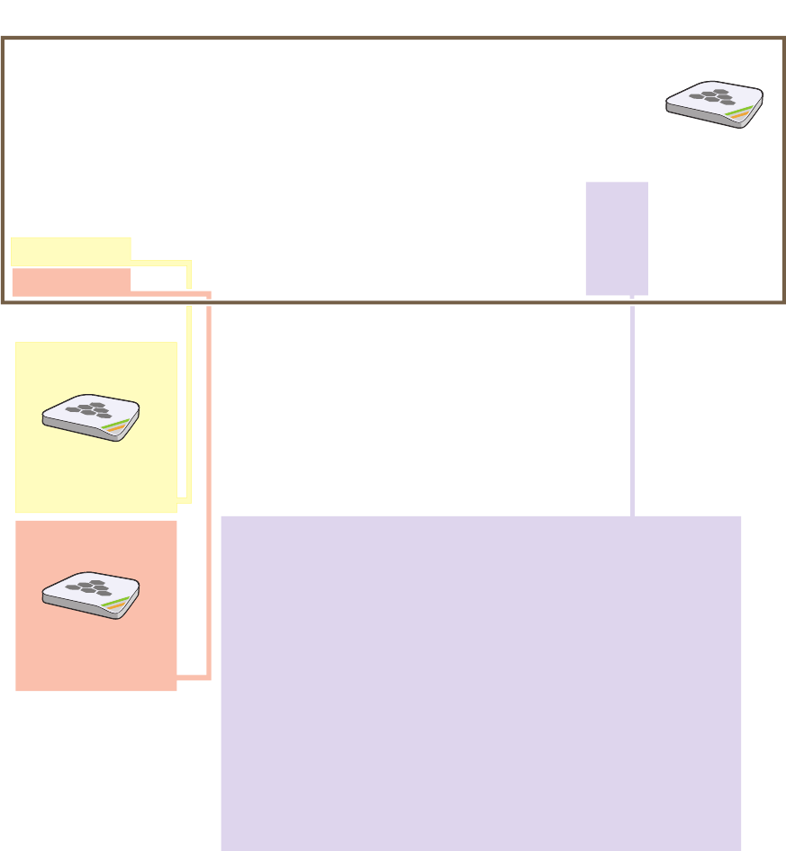
Chapter 10 Deployment Examples (CLI)
156 Aerohive
After HiveAP-3 boots up, it discovers the two other members of hive1 over a wireless backhaul link. The
members authenticate themselves and establish a security association for encrypting backhaul communications
among themselves. HiveAP-3 then learns its default route to the wired network from the other hive members. If
the other members send routes with equal costs—which is what happens in this example—HiveAP-3 uses the first
route it receives. When it learns this route, it can communicate with the DHCP server to get an IP address for its
mgt0 interface.
6. Check that HiveAP-3 has associated with the other members at the wireless level.
HiveAP-2
0019:7700:0438
wifi1.1 MAC Address
HiveAP-1
0019:7700:0028
wifi1.1 MAC Address
show hive hive1 neighbor
Chan=channel number; Pow=Power in dBm;
A-Mode=Authentication mode; Cipher=Encryption mode;
Conn-Time=Connected time; Hstate=Hive State;
Mac Addr Chan Tx Rate Rx Rate Pow A-Mode Cipher Conn-Time Hstate Phymode Hive
-------------- ---- ------- ------- --- ------ ------- --------- ------ ------- ----
0019:7700:0028 149 54M 54M -16 psk aes ccm 00:04:15 Auth 11a hive1
0019:7700:0438 149 54M 54M -16 psk aes ccm 00:04:16 Auth 11a hive1
Log in to HiveAP-3 and enter this command to see its neighbors in hive1:
HiveAP-3
In the output of the show hive hive1 neighbor
command, you can see hive-level and member-level
information. (On HiveAPs supporting 802.11n, the
channel width for hive communications—20 or 40
MHz—is also shown.)
When you see the MAC addresses of the other hive
members, you know that HiveAP-3 learned them over
a wireless backhaul link.
Neighbors
The following are the various hive states that can appear:
Disv (Discover) - Another HiveAP has been discovered, but there is a
mismatch with its hive ID.
Neibor (Neighbor) - Another HiveAP has been discovered whose hive
ID matches, but it has not yet been authenticated.
CandPr (Candidate Peer) - The hive ID on a discovered HiveAP
matches, and it can accept more neighbors.
AssocPd (Association Pending) - A HiveAP is on the same backhaul
channel, and an assocation process in progress.
Assocd (Associated) - A HiveAP has associated with the local HiveAP
and can now start the authentication process.
Auth (Authenticated) - The HiveAP has been authenticated and can
now exchange data traffic.
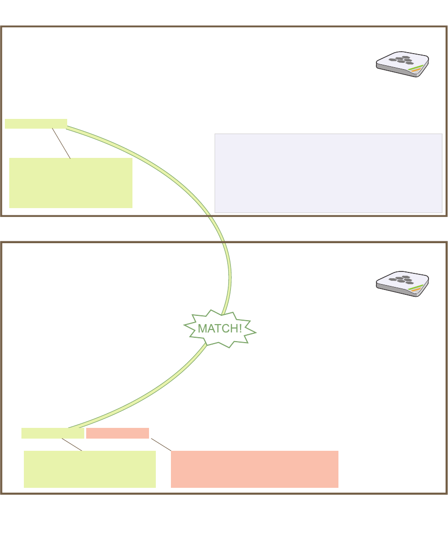
Deployment Guide 157
EXAMPLE 2: DEPLOYING A HIVE
7. To check that the hive members have full data connectivity with each other, associate a client in wireless
network-1 with HiveAP-1 (the SSID "employee" is already defined on clients in wireless network-1; see
"Deploying a Single HiveAP"). Then check if HiveAP-1 forwards the client’s MAC address to the others to store in
their roaming caches.
This MAC address is for the
wireless adapter of the client
(or “supplicant”) associated
with the SSID “employee”.
This MAC address is for the wifi0.1
subinterface of HiveAP-1, the HiveAP
with which the wireless client associated.
This is the same MAC address
for the client (station) that you
saw listed on HiveAP-1.
After associating a wireless client with HiveAP-1, log in to
HiveAP-1 and enter this command:
When you see the MAC address of the wireless client that is associated with HiveAP-1 in the roaming
cache of HiveAP-2, you know that HiveAP-1 and -2 are successfully sending data over the backhaul link.
Repeat this to confirm that HiveAP-3 also has a backhaul connection with the other members.
Then log in to HiveAP-2 and enter this command:
HiveAP-1
HiveAP-2
show roaming cache
Roaming Cache Table:
UID=User profile group ID; PMK=Pairwise Master Key;
TLC=PMK Time Left in Cache; Life=PMK Life; A=authenticated; L= CWP Logged In
Roaming for this HiveAP: enabled
Maximum Caching Time: 3600 seconds
Caching update interval: 60 seconds
Caching update times: 60
Roaming hops: 1
SSID employee:
Maximum Caching Time: 3600 seconds
Caching update interval: 60 seconds
Caching update times: 60
No. Supplicant Authenticator UID PMK PMKID Life Age TLC Hop AL
--- -------------- -------------- --- ----- ----- ---- ----- --- --- --
0 0016:cf8c:57bc 0019:7700:0024 0 1349* 1615* -1 46 195 1 YN
show ss
id employee station
Chan=channel number; Pow=Power in dBm;
A-Mode=Authentication mode; Cipher=Encryption mode;
A-Time=Associated time; Auth=Authenticated;
UPID=User profile Identifier; Phymode=Physical mode;
Mac Addr IP Addr Chan Tx Rate Rx Rate Pow A-Mode Cipher A-Time VLAN Auth UPID Phymode
-------------- ---------- ---- ------- ------- --- -------- ------- -------- ---- ---- ---- -------
0016:cf8c:57bc 10.1.1.73 1 54M 54M -40 wpa2-psk aes ccm 00:01:46 1 Yes 0 11b/g
Total station
count: 1
Note: On HiveAPs supporting IEEE 802.11n, there are
two additional columns for SM-PS (spatial multiplexing
power save) and channel width (20 or 40 MHz). The
SM-PS states can be “static” (use one data stream for
11a/b/g clients), “dynamic” (use multiple spatial streams
for 11n clients when the HiveAP sends an RTS frame),
or “disabled” (always use spatial streams for 11n clients).
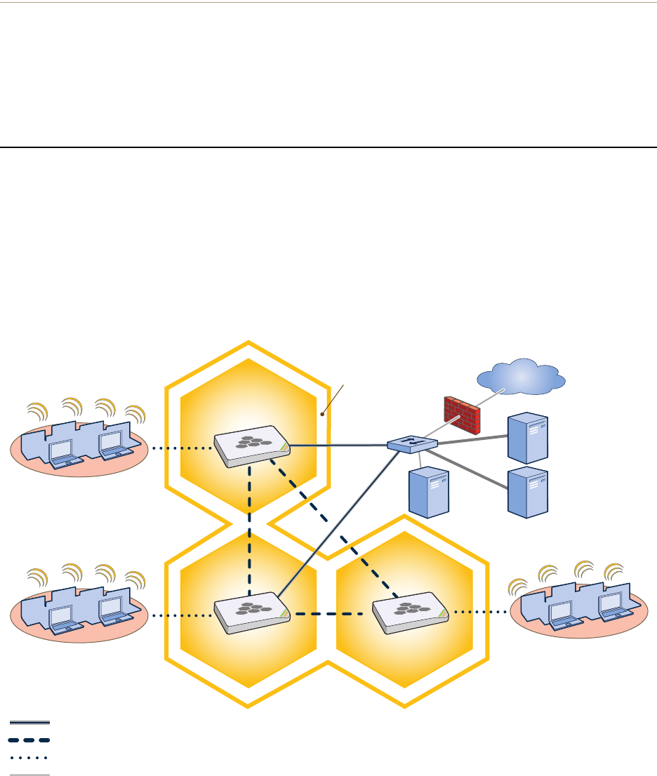
Chapter 10 Deployment Examples (CLI)
158 Aerohive
Step 4 Configure wireless clients
Define the "employee" SSID on all the wireless clients in wireless network-2 and -3. Specify WPA-PSK for network
authentication, AES or TKIP for data encryption, and the preshared key N38bu7Adr0n3.
The setup of hive1 is complete. Wireless clients can now associate with the HiveAPs using SSID "employee" and
access the network. The HiveAPs communicate with each other to share client associations (to support fast roaming)
and routing data (to select optimal data paths).
EXAMPLE 3: USING IEEE 802.1X AUTHENTICATION
In this example, you use a Microsoft AD (Active Directory) server and a RADIUS server to authenticate wireless
network users. To accomplish this, you make the following modifications to the hive set up in "Deploying a Hive":
• Configure settings for the RADIUS server on the HiveAPs
• Change the SSID parameters on the HiveAPs and wireless clients to use IEEE 802.1X
The basic network design is shown in Figure 3.
Figure 3 Hive and 802.1X Authentication
Wireless Network-1
Switch
Firewall
Internet
DHCP
Server
Wireless Network-2 Wireless Network-3
Wired Hive Backhaul Communications
HiveAP-1
HiveAP-2 HiveAP-3
Wireless Hive Backhaul Communications
Wireless Network Access Connections
The HiveAPs receive PEAP (Protected EAP) authentication requests
from clients and forward them inside RADIUS authentication packets
to the RADIUS server at 10.1.1.10. The RADIUS server is in turn
linked to the database of the Active Directory server on which all the
user accounts have previously been created and stored.
RADIUS Server
10.1.1.10
Active Directory
Server
Wired Ethernet Network Connections
Hive1
Deployment Guide 159
EXAMPLE 3: USING IEEE 802.1X AUTHENTICATION
Step 1 Define the RADIUS server on the HiveAP-1
Configure the settings for the RADIUS server (IP address and shared secret) on HiveAP-1.
aaa radius-server first 10.1.1.10 shared-secret s3cr3741n4bl0X
The IP address of the RADIUS server is 10.1.1.10, and the shared secret that HiveAP-1 and the RADIUS
server use to authenticate each other is "s3cr3741n4b10X". You must also enter the same shared secret
on the RADIUS server when you define the HiveAPs as access devices (see step 5).
Step 2 Change the SSID on HiveAP-1
1. Change the authentication method in the SSID.
ssid employee security protocol-suite wpa-auto-8021x
save config
The protocol suite requires WPA (Wi-Fi Protected Access) or WPA2 security protocol for authentication
and key management, AES or TKIP encryption, and user authentication through IEEE 802.1X.
2. Enter the show interface mgt0 command and note the dynamically assigned IP address of the mgt0
interface. You need to know this address to define HiveAP-1 as an access device on the RADIUS server in step 5.
exit
Step 3 Configure HiveAP-2 and HiveAP-3
1. Log in to HiveAP-2 through its console port.
2. Configure HiveAP-2 with the same commands that you used for HiveAP-1:
aaa radius-server first 10.1.1.10 shared-secret s3cr3741n4bl0X
ssid employee security protocol-suite wpa-auto-8021x
save config
3. Enter the show interface mgt0 command to learn its IP address. You need this address for step 5.
exit
4. Log in to HiveAP-3 and enter the same commands.
Step 4 Modify the SSID on the wireless clients
Modify the "employee" SSID on all the wireless clients in wireless network-2 and -3. Specify WPA or WPA2 for network
authentication, AES or TKIP for data encryption, and PEAP (Protected EAP) for user authentication.
Note: This example assumes that the RADIUS and AD servers were previously configured and populated with user
accounts that have been in use on a wired network (not shown). The only additional configuration on these
servers is to enable the RADIUS server to accept authentication requests from the HiveAPs.
Note: Although all HiveAPs in this example use the same shared secret, they can also use different secrets.
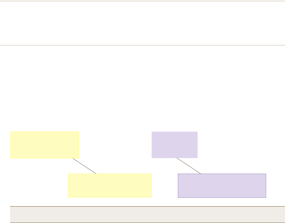
Chapter 10 Deployment Examples (CLI)
160 Aerohive
Step 5 Configure the RADIUS Server to accept authentication requests from the HiveAPs
Log in to the RADIUS server and define the three HiveAPs as access devices. Enter their mgt0 IP addresses (or
fully-qualified domain names) and shared secret.
Step 6 Check that clients can form associations and access the network
1. To check that a client can associate with a HiveAP and access the network, open a wireless client application
and connect to the "employee" SSID. Then contact a network resource, such as a web server.
2. Log in to the HiveAP CLI, and check that you can see the MAC address or the associated client and an indication
that the correct SSID is in use by entering the following command:
The setup for using IEEE 802.1X is complete. Wireless clients can now associate with the HiveAP using SSID
"employee", authenticate themselves through IEEE 802.1X to a RADIUS server, and access the network.
Note: You can also enter the following commands to check the association status of a wireless client:
show auth, show roaming cache, and show roaming cache mac <mac_addr>.
Check that the MAC and IP
addresses in the table match
those of the wireless client .
Check that the authentication and
encryption modes match those in
the SSID security protocol suite.
show ss
id employee station
Chan=channel number; Pow=Power in dBm;
A-Mode=Authentication mode; Cipher=Encryption mode;
A-Time=Associated time; Auth=Authenticated;
UPID=User profile Identifier; Phymode=Physical mode;
Mac Addr IP Addr Chan Tx Rate Rx Rate Pow A-Mode Cipher A-Time VLAN Auth UPID Phymode
-------------- ---------- ---- ------- ------- --- -------- ------- -------- ---- ---- ---- -------
0016:cf8c:57bc 10.1.1.73 1 54M 54M -40 8021x aes ccm 00:02:34 1 Yes 0 11b/g
Total station
count: 1

Deployment Guide 161
EXAMPLE 4: APPLYING QOS
EXAMPLE 4: APPLYING QOS
In this example, you want the hive members to prioritize voice, streaming media, and e-mail traffic. First, you map
distinguishing elements of these traffic types to three Aerohive QoS (Quality of Service) classes:
Class 6: voice traffic from VoIP phones with MAC OUI 00:12:3b (the OUI for all phones in the network)
Voice traffic is very sensitive to delay and cannot tolerate packet loss without loss of voice quality. When
other traffic is competing with voice traffic for bandwidth, it becomes essential to prevent that traffic from
interfering with voice traffic. Because voice traffic for a single call requires very little bandwidth—typically
from 8 to 64 Kbps depending on the voice codec used—a good approach for setting its rate is to calculate
the bandwidth necessary for a voice call plus related telephony traffic from a single user’s computer,
softphone, or handset and then multiply that by the potential number of concurrent VoIP users.
Class 5: streaming media using the MMS (Microsoft Media Server) protocol on TCP port 1755
Although streaming media is also time sensitive, streaming media software for both clients and servers
offers limited buffering to prevent choppy sounds and pixelated video when network congestion occurs.
Because congestion for more than a few seconds can adversely effect streaming media, it is important to
assign this type of traffic a higher priority than other types, but its priority should be lower than that for
voice, which is even more sensitive to delay.
Class 3: data traffic for e-mail using the following protocols:
SMTP (Simple Mail Transfer Protocol) on TCP port 25
POP3 (Post Office Protocol version 3) on TCP port 110
Then you create classifier profiles that reference these traffic-to-class mappings. You bind the profiles to the
wifi0.1 and eth0 interfaces so that hive members map the traffic matching these profiles that arrives at these
interfaces to the proper Aerohive classes.
You next define a QoS policy that defines how the hive members prioritize and process the traffic mapped to
Aerohive classes 6, 5, and 3. The QoS policy (named "voice") is shown in Figure 4 on page 162 and has these settings:
Class 6 (voice)
Forwarding: strict (Hive members forward traffic mapped to this class immediately without queuing it.)
Maximum rate for all class 6 traffic: 512 Kbps, which supports an 8- to 64-Kbps VoIP call (depending on the
compression that the codec provides) plus other telephony traffic such as DHCP, DNS, HTTP, and TFTP.
Class 5 (streaming media)
Forwarding: WRR (weighted round robin) with a weight of 90
By assigning class 5 a higher weight (90) than class 3 and 2 weights (class 3 = 60, class 2 = 30), you give
streaming media roughly a 3:2 priority over class 3 traffic and a 3:1 priority over class 2 traffic.
Maximum traffic rate for all class 5 traffic: 20,000 Kbps
You change the bandwidth available for streaming media when there is no competition for it (the
default rate for class 5 is 10,000 Kbps on HiveAPs that do not support the IEEE 802.11n standard and
50,000 Kbps on HiveAPs that do. However, you do not set the maximum rate (54,000 or 1,000,000 Kbps,
depending on the HiveAP model that you are configuring) to ensure that streaming media does not
consume all available bandwidth even if it is available.
Class 3 (e-mail)
Forwarding: WRR with a weight of 60
To help ensure that e-mail traffic remains flowing even when other types of data traffic compete with it
for available bandwidth, you elevate its priority by mapping SMTP and POP3 traffic to class 3 and giving
that class a higher weight (60) than the weight for class 2 traffic (30).
Maximum traffic rate for all class 3 traffic: 54,000 or 1,000,000 Kbps (the default, depending on the HiveAP)
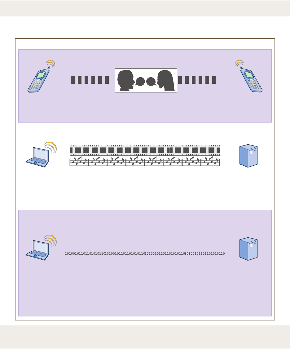
Chapter 10 Deployment Examples (CLI)
162 Aerohive
Figure 4 QoS Policy "voice" for Voice, Streaming Media, and Data
Finally, you create a user profile "employee-net" and apply the QoS policy "voice" to the user profile on each hive
member. You also configure the RADIUS server to return attributes in its authentication responses to indicate the
user group to which the hive members then assign users.
Note: The HiveAP assigns all traffic that you do not specifically map to an Aerohive class to class 2, which by
default uses WRR with a weight of 30 and a rate of 54,000 or 1,000,000 Kbps, depending on the HiveAP.
Note: This example assumes that the RADIUS and AD servers were previously configured and populated with user
accounts and have been serving a wired network (not shown). The only additional configuration is to
enable the RADIUS server to accept authentication requests from the HiveAPs.
qos policy voice qos 6 strict 512 0
The policy assigns the highest priority to voice traffic (class 6). For each voice session up to
512 Kbps, hive members provide “strict” forwarding; that is, they forward traffic immediately
without queuing it.
Voice
qos policy voice qos 5 wrr 20000 90
Because streaming media (class 5) needs more bandwidth than voice does, the policy
defines a higher forwarding rate for it: 20,000 Kbps. It sorts streaming media into forwarding
queues using the WRR (weighted round robin) mechanism. It also prioritizes streaming media
by assigning a higher weight (90) than it assigns data traffic (class 3 = 60, class 2 = 30).
Streaming
Media
qos policy voice qos 3 wrr { 54000 | 1000000 } 60
qos policy voice qos 2 wrr { 54000 | 1000000 } 30*
The policy sorts class 3 and 2 traffic into forwarding queues using WRR and defines the
highest forwarding rate: 54,000 Kbps or 1,000,000 Kbps, depending on the HiveAP model
that you are configuring. It gives class 3 (for e-mail protocols SMTP and POP3) a higher WRR
weight (60) so that the HiveAP queues more e-mail traffic in proportion to other types of traffic
in class 2, which has a weight of 30 by default. As a result, e-mail traffic has a better chance
of being forwarded than other types of traffic when bandwidth is scarce.
Class 2 is for all types of traffic not mapped to an Aerohive class—such as HTTP for example.
Data
QoS Policy: “voice”
* You do not need to enter this command because it just sets the default
values for class 2. It is shown to provide contrast with the previous command.

Deployment Guide 163
EXAMPLE 4: APPLYING QOS
Step 1 Map traffic types to Aerohive QoS classes on HiveAP-1
1. Map the MAC OUI (organizational unit identifier) of network users’ VoIP phones to Aerohive class 6.
qos classifier-map oui 00:12:3b qos 6
In this example, all network users use VoIP phones from the same vendor whose OUI (that is, the MAC
address prefix ) is 00:12:3b. When HiveAP-1 receives traffic from a client whose source MAC address
contains this OUI, it assigns it to Aerohive class 6.
2. Define the custom services that you need.
service mms tcp 1755
service smtp tcp 25
service pop3 tcp 110
The MMS (Microsoft Media Server) protocol can use several transports (UDP, TCP, and HTTP). However,
for a HiveAP to be able to map a service to an Aerohive QoS class, it must be able to identify that
service by a unique characteristic such as a static destination port number or a nonstandard protocol
number. Unlike MMS/UDP and MMS/HTTP, both of which use a range of destination ports, MMS/TCP uses
the static destination port 1755, which a HiveAP can use to map the service to an Aerohive class.
Therefore, you define a custom service for MMS using TCP port 1755. You also define custom services for
SMTP and POP3 so that you can map them to Aerohive class 3. By doing so, you can prioritize e-mail
traffic above other types of traffic that the HiveAP assigns to class 2 by default.
3. Map services to Aerohive classes.
qos classifier-map service mms qos 5
qos classifier-map service smtp qos 3
qos classifier-map service pop3 qos 3
Unless you map a specific service to an Aerohive QoS class, a HiveAP maps all traffic to class 2. In this
example, you prioritize voice, media, and e-mail traffic by assigning them to higher QoS classes than
class 2, and then by defining the forwarding and weighting mechanisms for each class (see step 3).
Step 2 Create profiles to check traffic arriving at interfaces on HiveAP-1
1. Define two classifier profiles for the traffic types "mac" and "service".
qos classifier-profile employee-voice mac
qos classifier-profile employee-voice service
qos classifier-profile eth0-voice mac
qos classifier-profile eth0-voice service
Classifier profiles define which components of incoming traffic HiveAP-1 checks. Because you specify
"mac" and "service", it checks the MAC address in the Ethernet frame header and the service type (by
protocol number in the IP packet header and port number in the transport packet header). If it detects
traffic matching a classifier-map, it maps it to the appropriate Aerohive class. However, before this can
happen, you must first associate the profiles with the interfaces that will be receiving the traffic that
you want checked. This you do with the next two commands.

Chapter 10 Deployment Examples (CLI)
164 Aerohive
2. Associate the classifier profiles with the employee SSID and the eth0 interface so that HiveAP-1 can classify
incoming traffic arriving at these two interfaces.
ssid employee qos-classifier employee-voice
interface eth0 qos-classifier eth0-voice
By creating two QoS classifiers and associating them with the employee SSID and eth0 interface,
HiveAP-1 can classify traffic flowing in both directions for subsequent QoS processing; that is, it can
classify traffic flowing from the wireless LAN to the wired LAN, and from the wired LAN to the wireless
LAN.
Step 3 Apply QoS on HiveAP-1
1. Create a QoS policy.
For HiveAPs supporting IEEE 802.11a/b/g:
qos policy voice qos 5 wrr 20000 90
qos policy voice qos 3 wrr 54000 60
For HiveAPs supporting IEEE 802.11a/b/g/n:
qos policy voice qos 6 strict 512 0
qos policy voice qos 5 wrr 20000 90
qos policy voice qos 3 wrr 1000000 60
By default, a newly created QoS policy attempts to forward traffic mapped to classes 6 and 7
immediately upon receipt. This immediate forwarding of received traffic is called "strict" forwarding. To
assign strict forwarding to VoIP traffic from phones whose MAC OUI is mapped to class 6, you simply
retain the default settings for class 6 traffic on HiveAPs supporting 802.11a/b/g data rates. For HiveAPs
supporting 802.11n data rates, the default user profile rate is 20,000 Kbps for class 6 traffic, so you
change it to 512 Kbps.
For classes 5 and 3, you limit the rate of traffic and set WRR (weighted round robin) weights so that the
HiveAP can control how to put the rate-limited traffic into forwarding queues. You use the default
settings for class 2 traffic.
When you enter any one of the above commands, the HiveAP automatically sets the maximum
bandwidth for all members of the user group to which you later apply this policy and the bandwidth for
any individual group member. You leave the maximum traffic rate at the default 54,000 Kbps or
1,000,000 Kbps—depending on the HiveAP model that you are configuring—for the user group. You also
leave the maximum bandwidth for a single user at 54,000 or 1,000,000 Kbps, so that if a single user
needs all the bandwidth and there is no competition for it, that user can use it all.
Also by default, the traffic rate for this policy has a weight of 10. At this point, because this is the only
QoS policy, the weight is inconsequential. If there were other QoS policies, then their weights would
help determine how the HiveAP would allocate the available bandwidth.
Note: If the surrounding network employs the IEEE 802.11p QoS classification system (for wired network
traffic) or 802.11e (for wireless network traffic), you can ensure that HiveAP-1 checks for them by
entering these commands:
qos classifier-profile eth0-voice 8021p
qos classifier-profile employee-voice 80211e
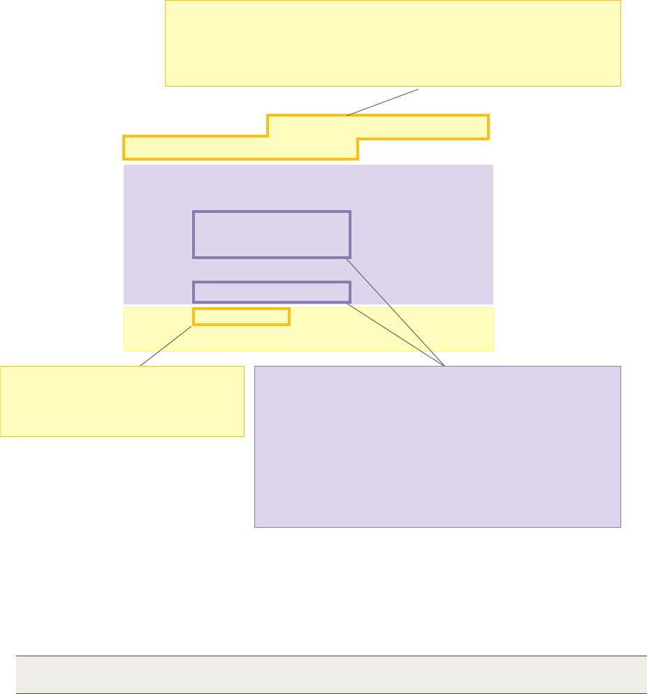
Deployment Guide 165
EXAMPLE 4: APPLYING QOS
The QoS policy that you define is shown in Figure 5. Although you did not configure settings for Aerohive QoS
classes 0, 1, 2, 4, and 7, the policy applies default settings to them. The HiveAP assigns all traffic that you do
not specifically map to an Aerohive class to class 2, which uses WRR with a weight of 30 and a default rate of
54,000 or 1,000,000 Kbps. Because nothing is mapped to classes 0, 1, 4, and 7, their settings are irrelevant.
Figure 5 QoS Policy "voice"
2. Create a user profile and apply the QoS policy to it.
user-profile employee-net qos-policy voice attribute 2
You apply the QoS policy "voice" to all users belonging to the user-profile "employee-net" with attribute
2. On the RADIUS server, you must configure attribute 2 as one of the RADIUS attributes that the RADIUS
server returns when authenticating users (see step 5 on page 167).
save config
exit
Note: When HiveAP-1 does not use RADIUS for user authentication, you must assign the user profile to an
SSID. To do that, use the following command: ssid employee default-user-profile-attr 2
The user profile rate defines the total amount of bandwidth for all users to
which this policy applies. The user rate defines the maximum amount for any
single user. The user rate can be equal to but not greater than the user profile
rate. (Note: The maximums shown here are for HiveAPs that support 802.11n
data rates. For other HiveAPs, the maximum rates are 54,000 Kbps.)
show qos policy voice
Policy name=voice; user rate limit=1000000kbps;
User profile rate=1000000kbps; user profile weight=10;
Class=0; mode=wrr; weight=10; limit=1000000kbps;
Class=1; mode=wrr; weight=20; limit=1000000kbps;
Class=2; mode=wrr; weight=30; limit=1000000kbps;
Class=3; mode=wrr; weight=60; limit=1000000kbps;
Class=4; mode=wrr; weight=50; limit=1000000kbps;
Class=5; mode=wrr; weight=90; limit=20000kbps;
Class=6; mode=strict; weight=0; limit=512kbps;
Class=7; mode=strict; weight=0; limit=20000kbps;
The forwarding mode for class 6 (voice)
is strict. The HiveAP forwards packets
belonging to this class immediately
without queuing them.
The forwarding mode for class 5 (streaming media) and 2 - 3
(data) is WRR (weighted round robin). The HiveAP forwards
traffic belonging to these classes by putting them into
forwarding queues. The weights determine how many bits per
second go into each queue. For every 30 bits that the HiveAP
queues for class 2, it queues approximately 60 bits for class 3,
and 90 bits for class 5. These amounts are approximations
because the HiveAP also has an internal set weights for traffic
in different classes that skews forwarding in favor of traffic
belonging to higher classes.

Chapter 10 Deployment Examples (CLI)
166 Aerohive
Step 4 Configure HiveAP-2 and HiveAP-3
1. Log in to HiveAP-2 through its console port.
2. Configure HiveAP-2 with the same commands that you used for HiveAP-1:
qos classifier-map oui 00:12:3b qos 6
service mms tcp 1755
service smtp tcp 25
service pop3 tcp 110
qos classifier-map service mms qos 5
qos classifier-map service smtp qos 3
qos classifier-map service pop3 qos 3
qos classifier-profile employee-voice mac
qos classifier-profile employee-voice service
qos classifier-profile eth0-voice mac
qos classifier-profile eth0-voice service
ssid employee qos-classifier employee-voice
interface eth0 qos-classifier eth0-voice
For HiveAPs supporting IEEE 802.11a/b/g:
qos policy voice qos 5 wrr 20000 90
qos policy voice qos 3 wrr 54000 60
For HiveAPs supporting IEEE 802.11a/b/g/n:
qos policy voice qos 6 strict 512 0
qos policy voice qos 5 wrr 20000 90
qos policy voice qos 3 wrr 1000000 60
user-profile employee-net qos-policy voice attribute 2
save config
exit
3. Log in to HiveAP-3 and enter the same commands.

Deployment Guide 167
EXAMPLE 5: LOADING A BOOTSTRAP CONFIGURATION
Step 5 Configure RADIUS server attributes
1. Log in to the RADIUS server and define the three HiveAPs as RADIUS clients.
2. Configure the following attributes for the realm to which the wireless user accounts in network-1, -2, and -3
belong:
• Tunnel Type = GRE (value = 10)
• Tunnel Medium Type = IP (value = 1)
• Tunnel Private Group ID = 2
The RADIUS server returns the above attributes for all wireless users it authenticates from network-1, -2, and -3.
The HiveAP uses the combination of returned RADIUS attributes to assign users to the user group 2 ("employee-net").
It does not use them to create a GRE tunnel, which the tunnel type attribute might lead you to think.
When there is more traffic than available bandwidth, the HiveAP applies the "voice" policy. It performs strict
forwarding for voice and uses a WRR (weighted round robin) scheduling discipline for directing streaming media and
data traffic to queues to await forwarding. The QoS configuration is complete.
EXAMPLE 5: LOADING A BOOTSTRAP CONFIGURATION
As explained in "HiveOS Configuration File Types" on page 145, a bootstrap config file is typically a small set of
commands to which a HiveAP can revert when the configuration is reset or if the HiveAP cannot load its current and
backup configs. If you do not define and load a bootstrap config, the HiveAP reverts to the default config in these
situations, which can lead to two potential problems:
• If both the current and backup configs fail to load on a HiveAP acting as a mesh point in a hard-to-reach
location—such as a ceiling crawlspace—the HiveAP would revert to the default config. Because a mesh point
needs to join a hive before it can access the network and the default config does not contain the hive settings
that the mesh point needs to join the hive, an administrator would need to crawl to the device to make a
console connection to reconfigure the HiveAP.
• If the location of a HiveAP is publicly accessible, someone could press the reset button on the front panel of the
device to return the configuration to its default settings, log in using the default login name and password
(admin, aerohive), and thereby gain complete admin access. (Note that you can disable the ability of the reset
button to reset the configuration by entering this command: no reset-button reset-config-enable)
A bootstrap configuration can help in both of these situations. For the first case, a bootstrap config with the
necessary hive membership settings can allow the HiveAP to connect to the network and thereby become accessible
over the network for further configuring. For the second case, a bootstrap config with a number of obstacles such as
a hard-to-guess login name and password and a disabled access subinterface can make the firmware inaccessible
and the device unusable.
HiveAP-1 and -2 are in locations that are not completely secure. HiveAP-3 is a mesh point in a fairly inaccessible
location. To counter theft of the first two HiveAPs and to avoid the nuisance of physically accessing the third HiveAP,
you define a bootstrap config file that addresses both concerns and load it on the HiveAPs.

Chapter 10 Deployment Examples (CLI)
168 Aerohive
Step 1 Define the bootstrap config on HiveAP-1
1. Make a serial connection to the console port on HiveAP-1, log in, and load the default config.
load config default
reboot
You do not want the bootstrap config to contain any of your previously defined settings from the current
config. Therefore, you load the default config, which has only default settings. When you begin with
the default config and enter the commands that define the bootstrap config, the bootstrap config will
have just those commands and the default config settings.
2. Confirm the reboot command, and then, when you are asked if you want to use the Aerohive Initial
Configuration Wizard, enter no.
3. Log in using the default user name admin and password aerohive.
4. Define admin login parameters for the bootstrap config that are difficult to guess.
admin root-admin Cwb12o11siNIm8vhD2hs password 8wDamKC1Lo53Ku71
You use the maximum number of alphanumeric characters for the login name (20 characters) and
password (16 characters). By mixing uppercase and lowercase letters with numbers in strings that do
not spell words or phrases, you make the login much harder to guess.
5. Leave the various interfaces in their default up or down states.
By default, the wifi0 and wifi0.1 interfaces are down, but the mgt0, eth0, wifi1, and wifi1.1
subinterfaces are up. The hive members need to use wifi1.1, which is in backhaul mode, so that
HiveAP-3 can rejoin hive1 and, through hive1, access DHCP and DNS servers to regain network
connectivity. (By default, mgt0 is a DHCP client.) You leave the eth0 interface up so that Hive-1 and
Hive-2 can retain an open path to the wired network. However, with the two interfaces in access
mode—wifi0 and wifi0.1— in the down state, none of the HiveAPs will be able provide network access to
any wireless clients. Wireless clients cannot form associations through wifi1.1 nor can a computer
attach through the eth0 interface—because it is also in backhaul mode—and obtain network access
through the mesh.
6. Define the hive settings so that any of the three HiveAPs using the bootstrap config can rejoin the grid.
hive hive1
hive hive1 password s1r70ckH07m3s
interface mgt0 hive hive1
When a HiveAP boots up using the bootstrap config, it can rejoin hive1 because the configuration
includes the hive name and password and binds the mgt0 interface to the hive. This is particularly
useful for HiveAP-3 because it is a mesh point and can only access the wired network after it has joined
the hive. It can then reach the wired network through either of the portals, HiveAP-1 or HiveAP-2.
7. Save the configuration as a bootstrap config.
save config running bootstrap
If anyone resets the current configuration, the HiveAP will load this bootstrap config and thwart any
thief from accessing the configuration and any wireless client from accessing the network.
Note: Be careful to remember the login name and password defined in a bootstrap config file. If they become
lost or forgotten, you must obtain a one-time login key from Aerohive technical support. To get the
key, you must already have had a support contract in place. The first one-time login key is free. After
that, there is a small handling fee for each additional key.

Deployment Guide 169
EXAMPLE 5: LOADING A BOOTSTRAP CONFIGURATION
Step 2 Save the bootstrap config to a TFTP server
1. Check the configurations to make sure the settings are accurate.
show config bootstrap
Check that the settings are those you entered in the previous step for the bootstrap config.
show config backup
Note that the backup config is the previous current config. This is the configuration that has all your
previously defined settings.
2. Return to the previous current config.
load config backup
reboot
3. When HiveAP-1 finishes rebooting, log back in using the login parameters you set in "Example 1: Deploying a
Single HiveAP" on page 150 (mwebster, 3fF8ha).
4. Check that the current config is the same as your previous current config.
show config current
5. Save the file as bootstrap-hive1.txt to the root directory of your TFTP server running on your management
system at 10.1.1.31, an address received by the same DHCP server and in the same subnet as the HiveAP
addresses.
save config bootstrap tftp://10.1.1.31:bootstrap-hive1.txt
Step 3 Load the bootstrap config file on HiveAP-2 and HiveAP-3
1. Make a serial connection to the console port on HiveAP-2 and log in.
2. Upload the bootstrap-hive1.txt config file from the TFTP server to HiveAP-2 as a bootstrap config.
save config tftp://10.1.1.31:bootstrap-hive1.txt bootstrap
3. Check that the uploaded config file is now the bootstrap config.
show config bootstrap
4. Repeat the procedure to load the bootstrap config on HiveAP-3.
The bootstrap configs are now in place on all three HiveAPs.

Chapter 10 Deployment Examples (CLI)
170 Aerohive
CLI COMMANDS FOR EXAMPLES
This section includes all the CLI commands for configuring the HiveAPs in the previous examples. The CLI
configurations are presented in their entirety (without explanations) as a convenient reference, and—if you are
reading this guide as a PDF—as an easy way to copy and paste the commands. Simply copy the blocks of text for
configuring the HiveAPs in each example and paste them at the command prompt.
Commands for Example 1
Enter the following commands to configure the SSID "employee" on the single HiveAP in "Deploying a Single HiveAP"
on page 150:
ssid employee
ssid employee security protocol-suite wpa-auto-psk ascii-key N38bu7Adr0n3
interface wifi0.1 ssid employee
save config
Commands for Example 2
Enter the following commands to configure three HiveAPs as members of "hive1" in "Deploying a Hive" on page 153:
HiveAP-1
hive hive1
hive hive1 password s1r70ckH07m3s
interface mgt0 hive hive1
save config
HiveAP-2
ssid employee
ssid employee security protocol-suite wpa-auto-psk ascii-key N38bu7Adr0n3
interface wifi0.1 ssid employee
hive hive1
hive hive1 password s1r70ckH07m3s
interface mgt0 hive hive1
save config
Note: The following sections omit optional commands, such as changing the login name and password, and
commands used to check a configuration.
Deployment Guide 171
EXAMPLE 5: CLI COMMANDS FOR EXAMPLES
HiveAP-3
ssid employee
ssid employee security protocol-suite wpa-auto-psk ascii-key N38bu7Adr0n3
interface wifi0.1 ssid employee
hive hive1
hive hive1 password s1r70ckH07m3s
interface mgt0 hive hive1
save config
Commands for Example 3
Enter the following commands to configure the hive members to support IEEE 802.1X authentication in "Using IEEE
802.1X Authentication" on page 158:
HiveAP-1
aaa radius-server first 10.1.1.10 shared-secret s3cr3741n4bl0X
ssid employee security protocol-suite wpa-auto-8021x
save config
HiveAP-2
aaa radius-server first 10.1.1.10 shared-secret s3cr3741n4bl0X
ssid employee security protocol-suite wpa-auto-8021x
save config
HiveAP-3
aaa radius-server 10.1.1.10 shared-secret s3cr3741n4bl0X
ssid employee security protocol-suite wpa-auto-8021x
save config
Chapter 10 Deployment Examples (CLI)
172 Aerohive
Commands for Example 4
Enter the following commands to configure the hive members to apply QoS (Quality of Service) to voice, streaming
media, and data traffic in "Applying QoS" on page 161:
HiveAP-1
qos classifier-map oui 00:12:3b qos 6
service mms tcp 1755
service smtp tcp 25
service pop3 tcp 110
qos classifier-map service mms qos 5
qos classifier-map service smtp qos 3
qos classifier-map service pop3 qos 3
qos classifier-profile employee-voice mac
qos classifier-profile employee-voice service
qos classifier-profile eth0-voice mac
qos classifier-profile eth0-voice service
ssid employee qos-classifier employee-voice
interface eth0 qos-classifier eth0-voice
For HiveAPs supporting IEEE 802.11a/b/g
qos policy voice qos 5 wrr 20000 90
qos policy voice qos 3 wrr 54000 60
For HiveAPs supporting IEEE 802.11a/b/g/n
qos policy voice qos 6 strict 512 0
qos policy voice qos 5 wrr 20000 90
qos policy voice qos 3 wrr 1000000 60
user-profile employee-net qos-policy voice attribute 2
save config
HiveAP-2
qos classifier-map oui 00:12:3b qos 6
service mms tcp 1755
service smtp tcp 25
service pop3 tcp 110
qos classifier-map service mms qos 5
qos classifier-map service smtp qos 3
qos classifier-map service pop3 qos 3
qos classifier-profile employee-voice mac
Deployment Guide 173
EXAMPLE 5: CLI COMMANDS FOR EXAMPLES
qos classifier-profile employee-voice service
qos classifier-profile eth0-voice mac
qos classifier-profile eth0-voice service
ssid employee qos-classifier employee-voice
interface eth0 qos-classifier eth0-voice
For HiveAPs supporting IEEE 802.11a/b/g
qos policy voice qos 5 wrr 20000 90
qos policy voice qos 3 wrr 54000 60
For HiveAPs supporting IEEE 802.11a/b/g/n
qos policy voice qos 6 strict 512 0
qos policy voice qos 5 wrr 20000 90
qos policy voice qos 3 wrr 1000000 60
user-profile employee-net qos-policy voice attribute 2
save config
HiveAP-3
qos classifier-map oui 00:12:3b qos 6
service mms tcp 1755
service smtp tcp 25
service pop3 tcp 110
qos classifier-map service mms qos 5
qos classifier-map service smtp qos 3
qos classifier-map service pop3 qos 3
qos classifier-profile employee-voice mac
qos classifier-profile employee-voice service
qos classifier-profile eth0-voice mac
qos classifier-profile eth0-voice service
ssid employee qos-classifier employee-voice
interface eth0 qos-classifier eth0-voice
For HiveAPs supporting IEEE 802.11a/b/g
qos policy voice qos 5 wrr 20000 90
qos policy voice qos 3 wrr 54000 60
For HiveAPs supporting IEEE 802.11a/b/g/n
qos policy voice qos 6 strict 512 0
qos policy voice qos 5 wrr 20000 90
qos policy voice qos 3 wrr 1000000 60
user-profile employee-net qos-policy voice attribute 2
save config
Chapter 10 Deployment Examples (CLI)
174 Aerohive
Commands for Example 5
Enter the following commands to create bootstrap config files and load them on the hive members in "Loading a
Bootstrap Configuration" on page 167:
bootstrap-security.txt
admin root-admin Cwb12o11siNIm8vhD2hs password 8wDamKC1Lo53Ku71
hive hive1
hive hive1 password s1r70ckH07m3s
interface mgt0 hive hive1
HiveAP-1
save config tftp://10.1.1.31:bootstrap-security.txt bootstrap
show config bootstrap
HiveAP-2
save config tftp://10.1.1.31:bootstrap-security.txt bootstrap
show config bootstrap
HiveAP-3
save config tftp://10.1.1.31:bootstrap-meshpoint.txt bootstrap
show config bootstrap

Deployment Guide 175
Chapter 11 Traffic Types
This is a list of all the types of traffic that might be involved with a HiveAP and HiveManager deployment. If a
firewall lies between any of the sources and destinations listed below, make sure that it allows these traffic types.
Traffic Supporting Network Access for Wireless Clients
Traffic Supporting Management of HiveAPs
Service Source Destination Protocol SRC
Port DST
Port Notes
DHCP unregistered
wireless client HiveAP wifi
subinterface in
access mode
17 UDP6867Required for captive web portal
functionality
DNS unregistered
wireless client HiveAP wifi
subinterface in
access mode
17 UDP 53, or
1024 -
65535
53 Required for captive web portal
functionality
GRE HiveAP mgt0
interface HiveAP mgt0
interface 47 GRE N.A. N.A. Required to support DNX* and layer
3 roaming between members of
different hives
* DNX = dynamic network extensions
HTTP unregistered
wireless client HiveAP wifi
subinterface in
access mode
6 TCP 1024 -
65535 80 Required for captive web portal
functionality
HTTPS unregistered
wireless client HiveAP wifi
subinterface in
access mode
6 TCP 1024 -
65535 443 Required for captive web portal
functionality using a server key
RADIUS
accounting HiveAP mgt0
interface RADIUS server 17 UDP 1024 -
65535 1813†Required to support RADIUS
accounting
RADIUS
authentication HiveAP mgt0
interface RADIUS server 17 UDP 1024 -
65535 1812†
† This is the default destination port number. You can change it to a different port number from 1 to 65535.
Required for 802.1X authentication
of users
Service Source Destination Protocol SRC
Port DST
Port Notes
CAPWAP*
* Control and Provisioning of Wireless Access Points
HiveAP mgt0
interface HiveManager
MGT or LAN
port
17 UDP 12222 12222 Required for HiveAPs to discover
the HiveManager and send it
alarms, events, and reports
NTP HiveAP mgt0
interface HiveManager
MGT or LAN
port
17 UDP 1024 -
65535 123 Required for HiveAP time
synchronization with the
HiveManager

Chapter 11 Traffic Types
176 Aerohive
Traffic Supporting Device Operations
Service Source Destination Protocol SRC
Port DST
Port Notes
SNMP HiveAP mgt0
interface SNMP manager 17 UDP 1024 -
65535 161 Required for reporting alarms and
events to an SNMP manager and to
HiveManager if not using CAPWAP
SNMP traps HiveAP mgt0
interface SNMP manager 17 UDP 1024 -
65535 162 Required for sending SNMP traps to
an SNMP manager and to
HiveManager if not using CAPWAP
SSHv2 HiveManager
MGT port HiveAP mgt0
interface 6 TCP 1024 -
65535 22 Required for the HiveManager to
manage and upload files to HiveAPs
Service Source Destination Protocol SRC
Port DST
Port Notes
Aerohive
Cooperative
Control Messages
HiveAP mgt0
interface HiveAP mgt0
interface 17 UDP 3000*
* This is the default destination port number. You can change it to a different port number from 1024 to 65535.
3000*Required for hive communications
and operates at layer 3
Aerohive
Cooperative
Control Messages
HiveAP wifi1.1
or eth0
interface
HiveAP wifi1.1
or eth0
interface
N.A. N.A. N.A. Required for hive communications
and operates at the LLC (Logical
Link Control) sublayer of layer 2
AeroScout
Reports AeroScout
engine HiveAP mgt0
interface 17 UDP 1024 -
65535 1144 Required to report tracked devices
to an AeroScout engine
DHCP HiveAP mgt0
interface DHCP server 17 UDP 68 67 By default, a HiveAP gets its IP
address through DHCP.
HTTPS management
system HiveManager
MGT port 6 TCP 1024 -
65535 443 Required for administration
through the HiveManager GUI
NTP HiveAP mgt0
interface, or
HiveManager
MGT port
NTP server 6 TCP 1024 -
65535 123 Required for time synchronization
with an NTP server
SMTP HiveManager
MGT port SMTP server 6 TCP 1024 -
65535 25 Required for the HiveManager to
send e-mail alerts to admins
SSHv2 management
system HiveAP mgt0
interface or
HiveManager
MGT port
6 TCP 1024 -
65535 22 Used for secure network access to
the HiveAP or HiveManager CLI, and
(SCP) for uploading files to and
downloading files from HiveAPs and
for uploading images to HiveAPs
and HiveManager
syslog HiveAP mgt0
interface syslog server 17 UDP 1024 -
65535 514 Required for remote logging to a
syslog server
Teln et mana gement
system HiveAP mgt0
interface 6 TCP,
17 UDP 1024 -
65535 23 Used for unsecured network access
to the HiveAP CLI
TFTP TFTP server or
mgt0 HiveAP mgt0
or TFTP server 17 UDP 1024 -
65535 69 Used for uploading files to and
downloading files from HiveAPs

Deployment Guide 177
Appendix A Country Codes
When the region code on a HiveAP is preset as "world", you must set a country code for the location where you
intend to deploy the HiveAP. This code determines the radio channels and power settings that the HiveAP can use
when deployed in that country. For HiveAPs intended for use in the United States, the region code is preset as
"FCC"—for "Federal Communications Commission"—and the country code is preset for the United States. You can see
the region code in the output of the show boot-param command.
To set a country code when the region is "world", enter the following command, in which number is the
appropriate country code number: boot-param country-code number
To apply radio settings for the updated country code, reboot the HiveAP by entering the reboot command.
The following list of country codes is provided for your convenience.
Countries and Country Codes
Albania 8
Algeria 12
Argentina 32
Armenia 51
Australia 36
Austria 40
Azerbaijan 31
Bahrain 48
Belarus 112
Belgium 56
Belize 84
Bolivia 68
Bosnia and Herzegovina 70
Brazil 76
Brunei Darussalam 96
Bulgaria 100
Canada 124
Chile 152
China (People’s Republic of China) 156
Colombia 170
Costa Rica 188
Croatia 191
Cyprus 196
Czech Republic 203
Denmark 208
Dominican Republic 214
Ecuador 218
Egypt 818
El Salvador 222
Estonia 233
Faeroe Islands 234
Finland 246
France 250
France2 255
Georgia 268
Germany 276
Note: Be sure to enter the correct country code. An incorrect entry might result in illegal radio operation and
cause harmful interference to other systems.
Appenidix A Country Codes
178 Aerohive
Greece 300
Guatemala 320
Honduras 340
Hong Kong (S.A.R., P.R.C) 344
Hungary 348
Iceland 352
India 356
Indonesia 360
Iran 364
Iraq 368
Ireland 372
Israel 376
Italy 380
Jamaica 388
Japan 392
Japan1 (JP1) 393
Japan2 (JP0) 394
Japan3 (JP1-1) 395
Japan4 (JE1) 396
Japan5 (JE2) 397
Japan6 (JP6) 399
Japan7 (J7) 4007
Japan8 (J8) 4008
Japan9 (J9) 4009
IJapan10 (J10) 4010
Japan11 (J11) 4011
Japan12 (J12) 4012
Japan13 (J13) 4013
Japan14 (J14) 4014
Japan15 (J15) 4015
Japan16 (J16) 4016
Japan17 (J17) 4017
Japan18 (J18) 4018
Japan19 (J19) 4019
Japan20 (J20) 4020
Japan21 (J21) 4021
Japan22 (J22) 4022
Japan23 (J23) 4023
Japan24 (J24) 4024
Jordan 400
Kazakhstan 398
Kenya 404
Korea (North Korea) 408
Korea (South Korea, ROC) 410
Korea (South Korea, ROC2) 411
Korea (South Korea, ROC3) 412
Kuwait 414
Latvia 428
Lebanon 422
Libya 434
Liechtenstein 438
Lithuania 440
Luxembourg 442
Macau 446
Macedonia (The Former Yugoslav Republic of
Macedonia) 807
Malaysia 458
Malta 470
Mexico 484
Monaco (Principality of Monaco) 492
Morocco 504
Netherlands 528
New Zealand 554
Nicaragua 558
Norway 578
Oman 512
Pakistan (Islamic Republic of Pakistan) 586
Panama 591
Paraguay 600
Peru 604
Philippines (Republic of the Philippines) 608
Poland 616
Deployment Guide 179
Appenidix A Country Codes
Portugal 620
Puerto Rico 630
Qatar 634
Romania 642
Russia 643
Saudi Arabia 682
Singapore 702
Slovakia (Slovak Republic) 703
Slovenia 705
South Africa 710
Spain 724
Sri Lanka 144
Sweden 752
Switzerland 756
Syria 760
Taiwan 158
Thailand 764
Trinidad y Tobago 780
Tunisia 788
Turkey 792
U.A.E. 784
Ukraine 804
United Kingdom 826
United States 840
United States (Public Safety; FCC49) 842
Uruguay 858
Uzbekistan 860
Venezuela 862
Vietnam 704
Yemen 887
Zimbabwe 716
Appenidix A Country Codes
180 Aerohive
This device is a transceiver. The data length as well as the timing is well controlled and
acknowkedged between Tx and Rx. Information or operational fail will terminate the
transmission and re-build the link immediately.