Aerohive Networks HIVEAP340 802.11 a/b/g/n access point User Manual Aerohive Deployment Guide
Aerohive Networks, Inc. 802.11 a/b/g/n access point Aerohive Deployment Guide
Contents
Users Manual 3
Deployment Guide 45
Chapter 4 The HiveAP 340 Platform
The Aerohive HiveAP 340 is a high-performance and highly reliable 802.11n wireless access point. The HiveAP 340
provides dual concurrent 802.11b/g/n and 802.11a/n radios for 3x3 MIMO (Multiple In, Multiple Out) and dual
10/100/1000 Ethernet ports for link aggregation or link redundancy. Its power management system uses a concept
called smart PoE (Power over Ethernet) to adjust its power consumption automatically in response the available
power in different environments. Smart PoE supports the IEEE 802.3af standard and the 802.3at pre-standard.
This chapter covers the following topics relating to the HiveAP:
•"HiveAP 340 Product Overview" on page 46
•"Ethernet and Console Ports" on page 48
•"Status LEDs" on page 52
•"Antennas" on page 52
•"Mounting the HiveAP 340" on page 56
•"Ceiling Mount" on page 56
•"Surface Mount" on page 58
•"Device, Power, and Environmental Specifications" on page 59
Chapter 4 The HiveAP 340 Platform
46 Aerohive
HIVEAP 340 PRODUCT OVERVIEW
The HiveAP 340 is a multi-channel wireless access point. It is compatible with IEEE 802.11b/g/n (2.4 GHz) and IEEE
802.11a/n (5 GHz) standards and supports a variety of Wi-Fi (wireless fidelity) security protocols, including WPA
(Wi-Fi Protected Access) and WPA2.
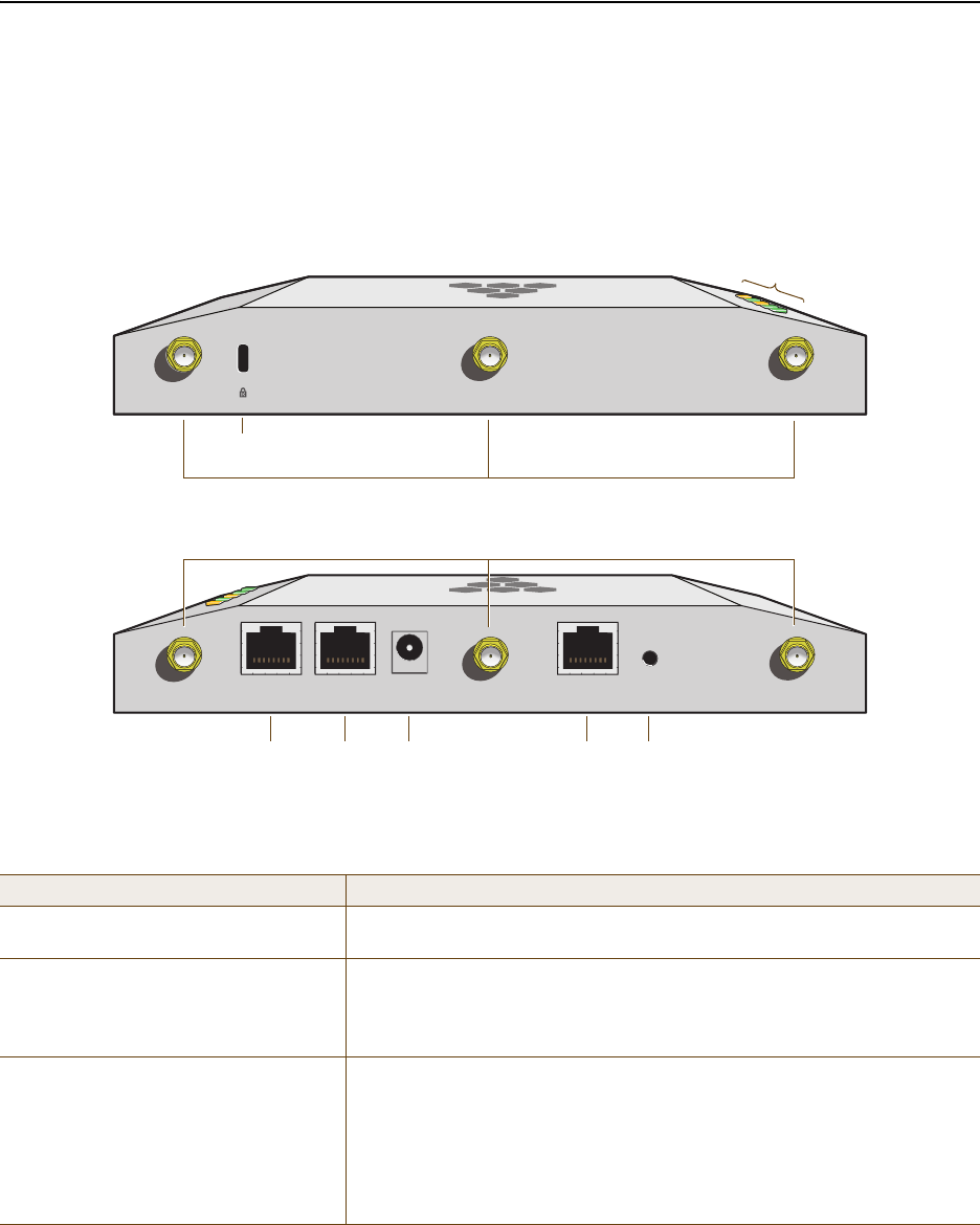
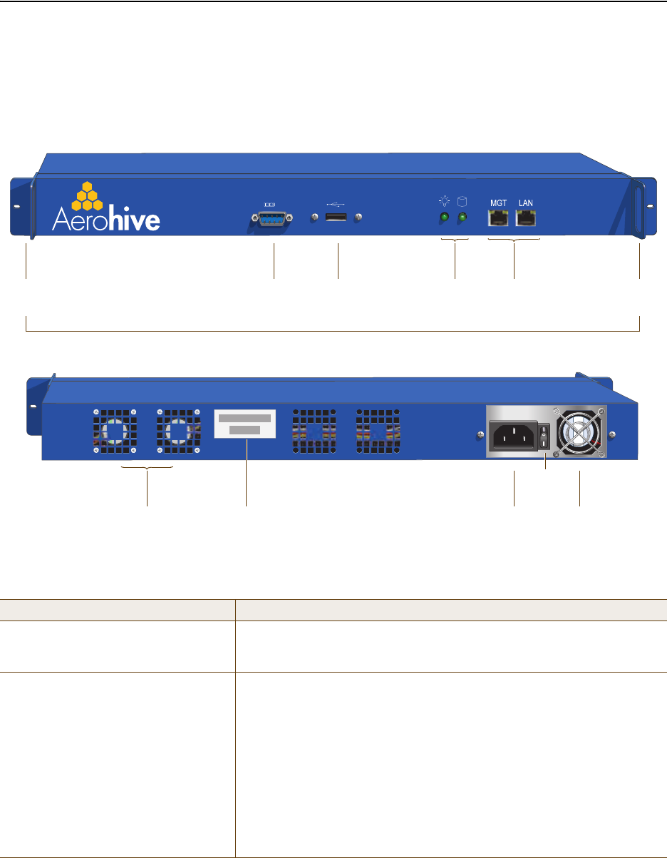
You can see the hardware components on the HiveAP in Figure 1. Each component is described in Table 1.
Figure 1 HiveAP 340 Hardware Components
Table 1 HiveAP 340 Component Descriptions
Component Description
Status LEDs The status LEDs convey operational states for system power, firmware,
Ethernet interfaces, and radios. For details, see "Status LEDs" on page 52.
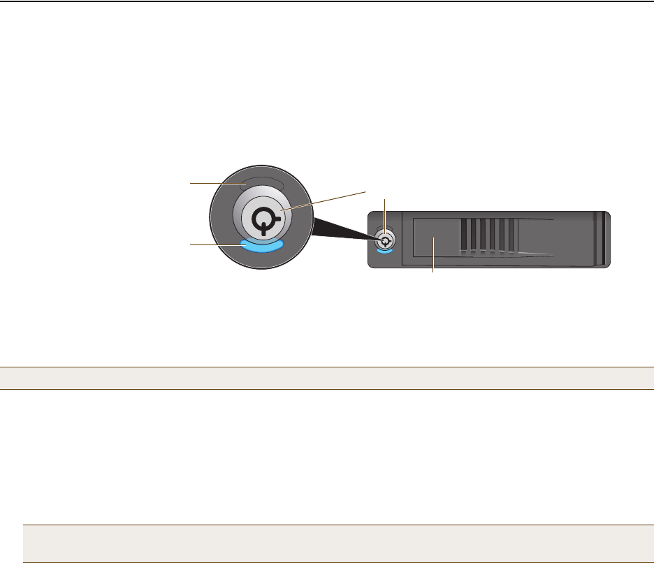
Device Lock Slot You can physically secure the HiveAP by attaching a lock and cable (such
as a Kensington® notebook lock) to the device lock slot or by using the
lock adapter that is included in the mounting kit and a padlock. For more
information, see "Locking the HiveAP 340" on page 57.
802.11a/b/g/n RP-SMA Connectors You can connect up to six detachable single-band antennas to the male
802.11a/b/g/n RP-SMA (reverse polarity-subminiature version A)
connectors. Connect the longer antennas, which support 2.4 GHz
frequencies (for IEEE 802.11b/g/n), to the connectors on the side panel
with the Ethernet ports. Connect the shorter antennas, which support 5
GHz frequencies (for IEEE 802.11a/n), to the connectors on the side panel
with the device lock slot. For details, see "Antennas" on page 52.
2.4 GHz (A) 2.4 GHz (B) 2.4 GHz (C)
ETH0 ETH1 48V DC
(.625A)
CONSOLE RESET
5 GHz (A)
5 GHz (B)5 GHz (C)
Power
Connector
10/100 /1000
Mbps PoE Ports Reset
Button
Console
Port
Device
Lock Slot
Status LEDs
802.11b/g/n RP-SMA Connectors for Detachable Single-Band Antennas
802.11a/n RP-SMA Connectors for Detachable Single-Band Antennas
Deployment Guide 47
HIVEAP 340 PRODUCT OVERVIEW
10/100/1000 Mbps PoE Ports The two 10/100/1000-Mbps Ethernet ports—ETH0 and ETH1—support IEEE
802.3af and 802.3at PoE (Power over Ethernet) and receive RJ-45
connectors. The HiveAP can receive power through one or both Ethernet
connections from power sourcing equipment (PSE) that is compatible with
the 802.3af standard and forthcoming 802.at standard. (If you connect
the HiveAP to a power source through the power connector and PoE ports
simultaneously, the device draws power through the power connector and
automatically disables PoE.)
You can configure ETH0 and ETH1 as two individual Ethernet interfaces,
combine them into an aggregate interface to increase throughput, or
combine them into a redundant interface to increase reliability. You can
connect the HiveAP 340 to a wired network or to a wired device (such as
a security camera) through these ports using bridging. They are
compatible with 10/100/1000Base-T/TX and automatically negotiate
half- and full-duplex connections with the connecting device. They are
autosensing and adjust to straight-through and cross-over Ethernet cables
automatically. For details, see "Ethernet and Console Ports" on page 48.
Power Connector The 48-volt DC power connector (0.625 amps) is one of two methods
through which you can power the HiveAP 340. To connect it to a 100 –
240-volt AC power source, use the AC/DC power adaptor that is available
as an extra option. Because the HiveAP does not have an on/off switch,
connecting it to a power source automatically powers on the device.
Console Port You can access the CLI by making a serial connection to the RJ-45 console
port. The management station from which you make a serial connection
to the HiveAP must have a VT100 emulation program, such as Tera Term
Pro© (a free terminal emulator) or Hilgraeve Hyperterminal® (provided
with Windows® operating systems). The following are the serial
connection settings: bits per second: 9600, data bits: 8, parity: none,
stop bits: 1, flow control: none. For details, see "Ethernet and Console
Ports" on page 48.
Reset Button The reset button allows you to reboot the device or reset the HiveAP to
its factory default settings. Insert a paper clip, or something similar, into
the Reset pinhole and press the reset button. To reboot the device, hold
the button down between 1 and 5 seconds. To return the configuration to
the factory default settings, hold it down for at least 5 seconds. After
releasing the button, the Power LED goes dark as the system reboots.
Then it pulses green while the firmware loads and the system performs a
self-test. After the software finishes loading, the Power LED glows steady
green.
To disable the reset button from resetting the configuration, enter this
command: no reset-button reset-config-enable Pressing the
button between 1 and 5 seconds will still reboot the HiveAP, but pressing
it for more than 5 seconds will not reset its configuration.
Note: The rear surface of the HiveAP 340 is used for heat dissipation to reduce the internal temperature.
Consequently, it can become hot, so use caution when handling it.
Component Description
Chapter 4 The HiveAP 340 Platform
48 Aerohive
Ethernet and Console Ports
There are three ports on the HiveAP 340: two RJ-45 10/100/1000Base-T/TX Ethernet ports and an RJ-45 console port.
The pin assignments in the PoE (Power over Ethernet) Ethernet ports follow the TIA/EIA-568-B standard (see
Figure 2). The ports accept standard types of Ethernet cable—cat3, cat5, cat5e, or cat6—and can receive power
over this cable from power sourcing equipment (PSE) that is 802.3af-compatible. If you use cat5, cat5e, or cat6
cables, the HiveAP 340 can also support 802.3at-compliant PSE. Such equipment can be embedded in a switch or
router, or it can come from purpose-built devices that inject power into the Ethernet line en route to the HiveAP.
Because the PoE ports have autosensing capabilities, the wiring termination in the Ethernet cable can be either
straight-through or cross-over.
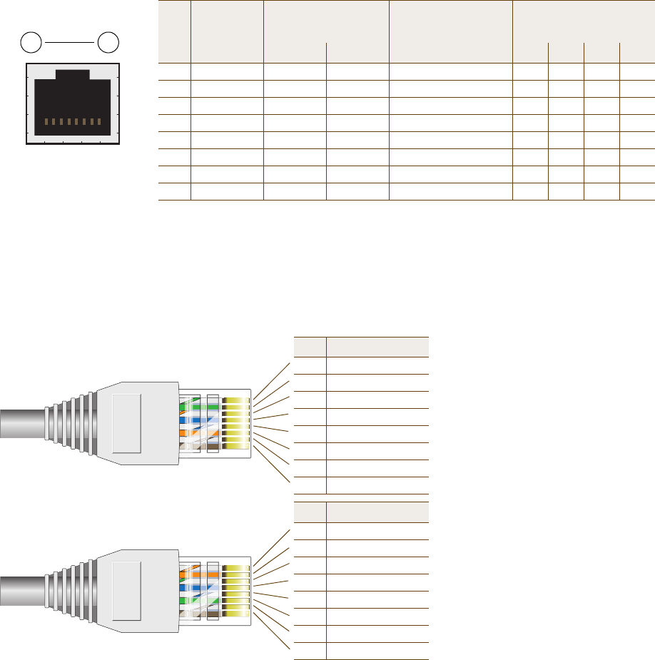
Figure 2 PoE Wire Usage and Pin Assignments
ETH0
Pin T568A Wire Color
1 White/Green
2 Green
3 White/Orange
4Blue
5 White/Blue
6 Orange
7 White/Brown
8Brown
(View of the ETH0 PoE
Port on the HiveAP 340)
8 1
Pin Numbers
Pin T568B Wire Color
1 White/Orange
2 Orange
3 White/Green
4Blue
5 White/Blue
6 Green
7 White/Brown
8Brown
T568A-Terminated Ethernet Cable
with an RJ-45 Connector
802.3af Alternative A
(Data and Power on
the Same Wires)
802.3af Alternative B
(Data and Power on
Separate Wires)
802.3at Wiring Options
Pin Data Signal MDI MDI-X MDI or MDI-X 1 2 3 4
1 Transmit + DC+ DC– – – – DC1+ DC1– DC1+ DC1–
2 Transmit - DC+ DC– – – – DC1+ DC1– DC1+ DC1–
3 Receive + DC– DC+ – – – DC1– DC1+ DC1– DC1+
4 (unused) – – – – – – DC+ DC2+ DC2+ DC2– DC2–
5 (unused) – – – – – – DC+ DC2+ DC2+ DC2– DC2–
6 Receive - DC– DC+ – – – DC1– DC1+ DC1– DC1+
7 (unused) – – – – – – DC– DC2– DC2– DC2+ DC2+
8 (unused) – – – – – – DC– DC2– DC2– DC2+ DC2+
MDI = Medium dependent interface for straight-through connections
MDI-X = Medium dependent interface for cross-over (X) connections
The PoE ports are auto-sensing and can automatically adjust to transmit and receive data over straight-through or cross-over Etherne
connections. Likewise, they can automatically adjust to 802.3af Alternative A and B power delivery methods. Furthermore, when the
Alternative A method is used, the ports automatically allow for polarity reversals depending on their role as either MDI or MDI-X. In
802.3at, the 1/2 and 3/6 wire pairs connect to DC source 1 and 4/5 and 7/8 pairs to DC source 2 in PSE. Although the exact polarity
depends on the PSE design, the HiveAP 340 Ethernet ports can support all possible options.
T568B -terminated Ethernet Cable
with an RJ-45 Connector
T568A and T568B are two standard
wiring termination schemes. Note that
the only difference between them is
that the white/green + solid green pair
of wires and the white/orange + solid
orange pair are reversed.
For straight-through Ethernet
cables—using either the T568A or
T568B standard—the eight wires
terminate at the same pins on each
end.
For cross-over Ethernet cables, the
wires terminate at one end according
to the T568A standard and at the
other according to T568B.
Deployment Guide 49
HIVEAP 340 PRODUCT OVERVIEW
Smart PoE
The HiveAP 340 applies the Aerohive concept of smart PoE to adjust power consumption as necessitated by varying
levels of available power. If the HiveAP needs more power than is available, it first disables the ETH1 interface. If it
still needs more power, it switches from 3x3 MIMO (Multiple In, Multiple Out) to 2x3 (see "MIMO" on page 53). In rare
cases when further power conservation is necessary, the HiveAP then reduces the speed on ETH0 from 10/100/1000
Mbps to 10/100 Mbps. Finally, in the event that there is a problem with the PoE switch or Ethernet cable, the HiveAP
disables its wireless interfaces and returns its ETH0 and ETH1 interfaces to 10/100/1000 Mbps speeds. Through the
application of smart PoE, the HiveAP 340 can make power usage adjustments so that it can continue functioning
even when the available power level drops.
Aggregate and Redundant Interfaces
By default ETH0 and ETH1 act as two individual Ethernet interfaces. When both interfaces are connected to the
network and are in backhaul mode, the HiveAP transmits broadcast traffic only through ETH0. The HiveAP transmits
broadcast traffic through ETH1 only when ETH0 does not have network connectivity. When both Ethernet interfaces
are connected to the network and are in access mode, then the HiveAP transmits broadcast traffic through all the
access interfaces: ETH0, ETH1, and all wireless subinterfaces in access mode.
In addition to using ETH0 and ETH1 as individual interfaces, you can combine them into an aggregate interface
(agg0) to increase throughput, or combine them into a redundant interface (red0) to increase reliability. The logical
red0 and agg0 interfaces support all the settings that you can configure for Ethernet interfaces except those
pertaining to physical link characteristics such as link speed. See the sections below for configuration information.
Aggregate Interface
You can increase throughput onto the wired network by combining ETH0 and ETH1 into a single logically aggregated
interface called "agg0". The aggregate interface effectively doubles the bandwidth that each physical has when
used individually. In this configuration, both Ethernet ports actively forward traffic, the HiveAP applying an internal
scheduling mechanism based on the source MAC address of each packet to send traffic through the aggregate
member interfaces. To configure an aggregate interface, enter the following commands:
interface eth0 bind agg0
interface eth1 bind agg0
In addition to configuring the HiveAP, you must also configure the connecting switch to support EtherChannel. For
example, the following commands bind two physical Ethernet ports—0/1 and 0/2—to the logical interface
port-channel group 1 on a Cisco Catalyst 2900 switch running Cisco IOS 12.2:
Switch#conf t
Switch(config)#interface port-channel 1
Switch(config-if)#switchport mode access
Switch(config-if)#spanning-tree portfast
Switch(config-if)#exit
Switch(config)#interface fastEthernet 0/1
Switch(config-if)#switchport mode access
Switch(config-if)#channel-group 1 mode on
Switch(config-if)#spanning-tree portfast
Switch(config-if)#exit

Chapter 4 The HiveAP 340 Platform
50 Aerohive
Switch(config)#int fastEthernet 0/2
Switch(config-if)#switchport mode access
Switch(config-if)#channel-group 1 mode on
Switch(config-if)#spanning-tree portfast
Switch(config-if)#exit
Switch(config)#exit
Switch#wr mem
Finally, you must cable the Cisco switch and the HiveAP together: Cisco 0/1 to HiveAP eth0, and Cisco 0/2 to HiveAP
eth1.
Redundant Interface
If a single Ethernet link provides sufficient bandwidth and speed, such as a 1000 Mbps link, but you want to ensure
link redundancy, you can connect the two Ethernet ports to the same switch—or to two different switches—and
configure them to act as a redundant interface called "red0". In this mode, only one Ethernet interface is actively
forwarding traffic at any one time. If eth0 is active and eth1 is passive and eth0 loses its connection, the HiveAP
switches over to eth1. To configure a redundant interface, enter the following commands:
interface eth0 bind red0 primary
interface eth1 bind red0
The interface that you specify as primary is the one that the HiveAP uses when both interfaces have network
connectivity. Because the HiveAP uses eth0 as the primary interface, it is unnecessary to specify "primary" in the
first command above. However, it is included to make the role of eth0 as the primary interface obvious.
Interface Selection for the Default Route
In cases where there are multiple active interfaces in backhaul mode, the HiveAP uses the following logic to choose
which interface to use in its default route:
• If there is an Ethernet interface and a wireless interface in backhaul mode, the HiveAP uses the Ethernet
interface in its default route.
• If there are multiple Ethernet interfaces in backhaul mode, the HiveAP chooses which one to use in its default
route in the following order:
• It uses red0 or agg0 if one of them has at least one member interface bound to it and its link state is UP.
• It uses ETH0 if neither red0 nor agg0 has any member interfaces and the link state for ETH0 is UP.
• It uses ETH1 if neither red0 nor agg0 has any member interfaces, the link state for ETH0 is DOWN, and the
link state for ETH1 is UP.
Note: No extra configuration is necessary on the connecting switch or switches to support a redundant interface.
Deployment Guide 51
HIVEAP 340 PRODUCT OVERVIEW
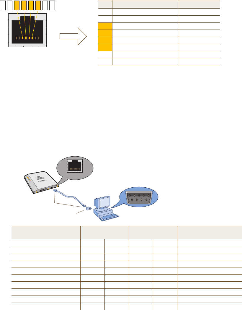
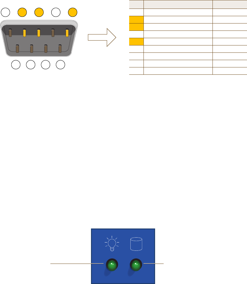
Console Port
The pin-to-signal mapping in the RJ-45 console port is shown shown in Figure 3.
Figure 3 Console Port Pin Assignments
To make a serial connection between your management system and the HiveAP, you can use the console cable that
is available as an extra option. Insert the RJ-45 connector into the HiveAP 340 console port, and attach the DB-9
connector to the serial (or COM) port on your management system. The management system must have a VT100
terminal emulation program, such as Tera Term Pro© (a free terminal emulator) or Hilgraeve Hyperterminal®
(provided with Windows® operating systems). If you want to make your own serial cable and adapter, refer to
Figure 3.
Figure 4 Wiring Details for Making a Serial Cable with an RJ-45-to-Female DB-9 Adapter
CONSOLE
Pin Signal Direction
1 RTS (Request to Send) Output, unused
2 DTR (Data Terminal Ready) Output, unused
3 TXD (Transmitted Data) Output
4 Ground Ground
5 Ground Ground
6 RXD (Received Data) Input
7 DSR (Data Set Ready) Input, unused
8 CTS (Clear to Send) Input, unused
RJ-45 Console Port
(View of the console
port on the HiveAP) Because this is a console port, only pins 3, 4, 5, and 6 are currently in use.
Console Port Pin Assignments
613457 28
Rollover Cable with
RJ-45 Connectors
RJ-45-to-Female DB-9 Adapter
Console Port
COM Port
(on Back Panel)
CONSOLE
Management System
HiveAP 340
Console Port
(HiveAP 340) RJ-45-to-RJ-45
Rollover Cable RJ-45-to-Female
DB-9 Adapter Management
System
Signal RJ-45 Pin RJ-45 Pin RJ-45 Pin DB-9 Pin Signal
RTS (Request to Send) 1 8 1 8 CTS (unused)
DTR (Data Terminal Ready) 2 7 2 6 DSR (unused)
TXD (Transmitted Data) 3 6 3 2 RXD
Ground 4 5 4 5 Ground
Ground 5 4 5 5 Ground
RXD (Received Data) 6 3 6 3 TXD
DSR (Data Set Ready) 7 2 7 4 DTR (unused)
CTS (Clear to Send) 8 1 8 7 RTS (unused)
- - - - 9 RI (Ring Indicator, unused)
Chapter 4 The HiveAP 340 Platform
52 Aerohive
Status LEDs
The five status LEDs on the top of the HiveAP 340 indicate various states of activity through their color (dark, green,
amber, and red) and illumination patterns (steady glow or pulsing). The meanings of the various color + illumination
patterns for each LED are explained below.
Power
•Dark: No power
• Steady green: Powered on and the firmware is running normally
• Pulsing green: Firmware is booting up
• Steady amber: Alarm indicating a firmware issue has occurred
• Pulsing amber: Firmware is being updated
• Steady red: Alarm indicating a hardware issue has occurred
ETH0 and ETH1
• Dark: Ethernet link is down or disabled
• Steady green: 1000 Mbps Ethernet link is up but inactive
• Pulsing green: 1000 Mbps Ethernet link is up and active
• Steady amber: 10/100 Mbps Ethernet link is up but inactive
• Pulsing amber: 10/100 Mbps Ethernet link is up and active
WIFI0 and WIFI1
• Dark: Wireless interface is disabled
• Steady green: Wireless interface is in access mode but inactive
• Pulsing green: Wireless interface is in access mode and active
• Steady amber: Wireless interface is in backhaul mode but inactive
• Pulsing amber: Wireless interface is in backhaul mode and active
• Alternating green and amber: Wireless interface is in backhaul mode and is searching for other hive
members
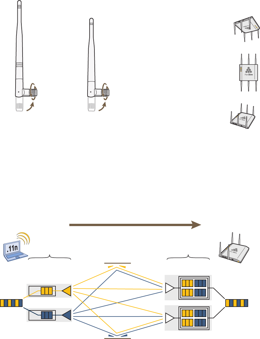
Antennas
The HiveAP 340 can accept up to six detachable dipole antennas. The three shorter antennas are designed for the 5
GHz band and have a 2-dBi gain. The three longer antennas are designed for the 2.4 GHz band and have a 4.9-dBi
gain. These antennas are omnidirectional, providing fairly equal coverage in all directions in a toroidal
(donut-shaped) pattern around each antenna (see Figure 4 on page 28). For greater coverage on a horizontal plane,
it is best to orient the antennas vertically. So that you can easily do that whether the HiveAP chassis is mounted
horizontally or vertically, the antennas hinge and swivel (see Figure 5 on page 53.)
Although hive members automatically adjust their signal strength according to their environments, you can resize
the area of coverage by increasing or decreasing the signal strength manually by entering the interface {
wifi0 | wifi1 } radio power <number> command, where <number> can be from 1 to 20 and represents
a value in dBm.
Deployment Guide 53
HIVEAP 340 PRODUCT OVERVIEW
Figure 5 HiveAP 340 Antennas
MIMO
MIMO (Multiple In, Multiple Out) is a major WLAN advancement introduced in the IEEE 802.11n standard in which
multiple RF links are formed on the same channel between the transmitter and receiver simultaneously. To
accomplish this, the transmitter separates a single data stream into multiple spatial streams, one for each RF chain
(an antenna + various digital signal processing modules linked to the antenna). The transmit antennas at the end of
each RF chain then transmit their spatial streams. The recipient’s receive antennas obtain streams from all the
transmit antennas. In fact, due to multipath, they receive multiple streams from each transmit antenna. The
receive antennas pass the spatial streams to the digital signal processors in their RF chains, which take the best data
from all the spatial streams and reassemble them into a single data stream once again (see Figure 6).
Figure 6 2x2 MIMO (2 Transmit Antennas x 2 Receive Antennas)
5 GHz Antenna for IEEE
802.11a/n
Length when fully
extended: 5 15/16” (15 cm)
2.4 GHz Antenna for
IEEE 802.11b/g/n
Length when fully
extended: 7 7/8” (20 cm)
The base of the antennas hinge up to 90 degrees so that you
can orient the antennas independently of the orientation of
the HiveAP chassis. The antennas also rotate in a full circle.
When mounting the HiveAP
340 on a ceiling, orient its
antennas downward.
When mounting the HiveAP
on a wall or post, fully extend
its antennas upward and
downward.
When mounting the HiveAP
above a ceiling or on a
horizontal beam, orient its
antennas upward.
Generally, orient the antennas vertically for
improved radio coverage, as shown here:
Transmit
Antennas
Digital Signal
Processors
RF Chains RF Signals (Multipath)
Receive
Antennas Digital Signal
Processors
RF Chains
802.11n wireless client
with two antennas HiveAP 340 using
two antennas
Object
Data Reassembled
Data
Chapter 4 The HiveAP 340 Platform
54 Aerohive
In previous 802.11 standards, access points and clients each employed a single set of components, or RF chain, for
transmitting or receiving. Although two antennas are often used for diversity, only the one with the best
signal-to-noise ratio is used at any given moment, and that antenna makes use of the single RF chain while the other
antenna remains inactive. A significant improvement that MIMO introduces is to permit each antenna to have its
own RF chain and for all antennas to function simultaneously. For the HiveAP 340, you can connect up to three
antennas per radio and configure the radio to use two or three transmit chains and two or three receive chains.1
Using two or three transmit and receive chains simultaneously increases the amount of data that can flow across the
WLAN and accelerates the processing of that data at each end of the wireless link.
Another major aspect of MIMO is how it turns multipath signals from a curse to a boon. As a radio signal moves
through space, some objects reflect it, others interfere with it, and still others absorb it. The receiver can end up
receiving multiple copies of the original signal, all kind of muddled together. However, the digital signal processors
in the multiple receive chains are able to combine their processing efforts to sort through all the received data and
reconstruct the original message. Furthermore, because the transmitter makes use of multiple RF chains, there is
an even richer supply of signals for the receive chains to use in their processing. To set the transmit and receive RF
chains for a radio profile, enter the following commands:
radio profile <name> transmit-chain { 2 | 3 }
radio profile <name> receive-chain { 2 | 3 }
There are two sets of antennas—three antennas per set—that operate concurrently in two different frequency
ranges: 2.4 GHz (IEEE 802.11b/g/n) and 5 GHz (IEEE 802.11a/n). Using two different frequency ranges reduces the
probability of interference that can occur when numerous channels operate within the same range. Conceptually,
the relationship of antennas and radios is shown in Figure 7.
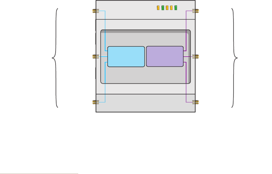
Figure 7 Antennas and Radios
\
The wifi0 interface links to radio 1 (frequency range = 2.4 GHz for IEEE 802.11b/g), and the wifi1 interface links to
radio 2 (frequency range = 5 GHz for IEEE 802.11a). These interface-to-radio relationships are permanent.
When deciding how many antennas to use, consider the types of wireless clients—802.11n only, 802.11g/n,
802.11b/g/n, or 802.11a/n—the area needing coverage, and the RF environment.
1. The convention for presenting the configuration of transmitting and receiving MIMO RF chains is TxR. For
example, a HiveAP 340 radio functioning in access mode might be configured to use two RF chains for
transmitting and three for receiving. In that case, its configuration can be presented as "2x3". In general, the
number of receive antennas is equal to or greater than the number of transmit antennas.
PWR
ETH1
ETH0
WIFI1
WIFI0
Radio 1
RF 802.11b/g/n
2.4 GHz
Radio 2
RF 802.11a/n
5 GHz
2.4 GHz (A)
2.4 GHz (B)
2.4 GHz (C)
5 GHz (A)
5 GHz (B)
5 GHz (C)
RP-SMA
Connectors
RP-SMA
Connectors
Cut-away view of the HiveAP 340 to show the relationship of the antennas and the two internal radios
Deployment Guide 55
HIVEAP 340 PRODUCT OVERVIEW
Using MIMO with Legacy Clients
In addition to supporting up to 300-Mbps throughput per radio for 802.11n clients, MIMO (Multiple In, Multiple Out)
can improve the reliability and speed of legacy 802.11a/b/g client traffic. When an 802.11a/b/g access point does
not receive acknowledgement that a frame it sent was received, it resends that frame, possibly at a somewhat
lower transmission rate. If the access point must continue resending frames, it will continue lowering its
transmission rate. As a result, clients that could get 54-Mbps throughput in an interference-free environment might
have to drop to 48- or 36-Mbps speeds due to multipath interface. However, because MIMO technology makes better
use of multipath, an access point using MIMO can continue transmitting at 54 Mbps, or at least at a better rate than
it would in a pure 802.11a/b/g environment, thus improving the reliability and speed of 802.11a/b/g client traffic.
Although 802.11a/b/g client traffic can benefit somewhat from an 802.11n access point using MIMO, supporting such
legacy clients along with 802.11n clients can have a negative impact on 802.11n client traffic. Legacy clients take
longer to send the same amount of data as 802.11n clients. Consequently, legacy clients consume more airtime than
802.11n clients do, causing greater congestion in the WLAN and reducing 802.11n performance.
By default, the HiveAP 340 supports 802.11a/b/g clients. You can restrict access only to clients using the IEEE
802.11n standard. By only allowing traffic from clients using 802.11n, you can increase the overall bandwidth
capacity of the access point so that there will not be an impact on 802.11n clients during times of network
congestion. To do that, enter the following command:
radio profile <string> 11n-clients-only
You can also deny access just to clients using the IEEE 802.11b standard, which has the slowest data rates of the
three legacy standards, while continuing to support 802.11a and 802.11g clients. To do that, enter the following
command:
no radio profile <string> allow-11b-clients
By blocking access to 802.11b clients, their slower data rates cannot clog the WLAN when the amount of wireless
traffic increases.
Chapter 4 The HiveAP 340 Platform
56 Aerohive
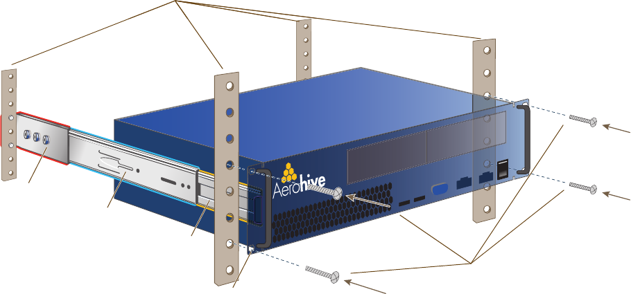
MOUNTING THE HIVEAP 340
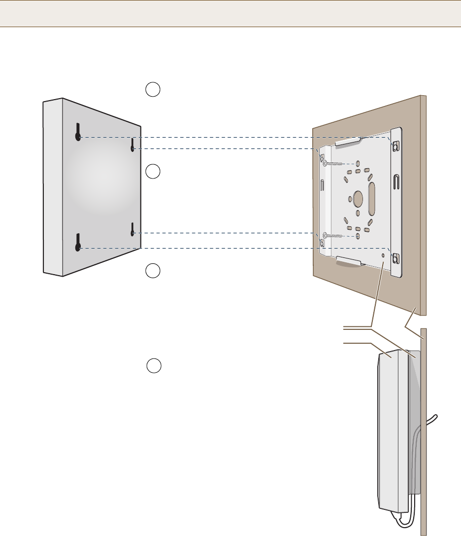
Using the mounting plate and track clips, you can mount the HiveAP 340 to the tracks of a dropped ceiling grid.
Using just the mounting plate, you can mount the HiveAP to any surface that can support its weight (3.3 lb., 1.5 kg).
Ceiling Mount
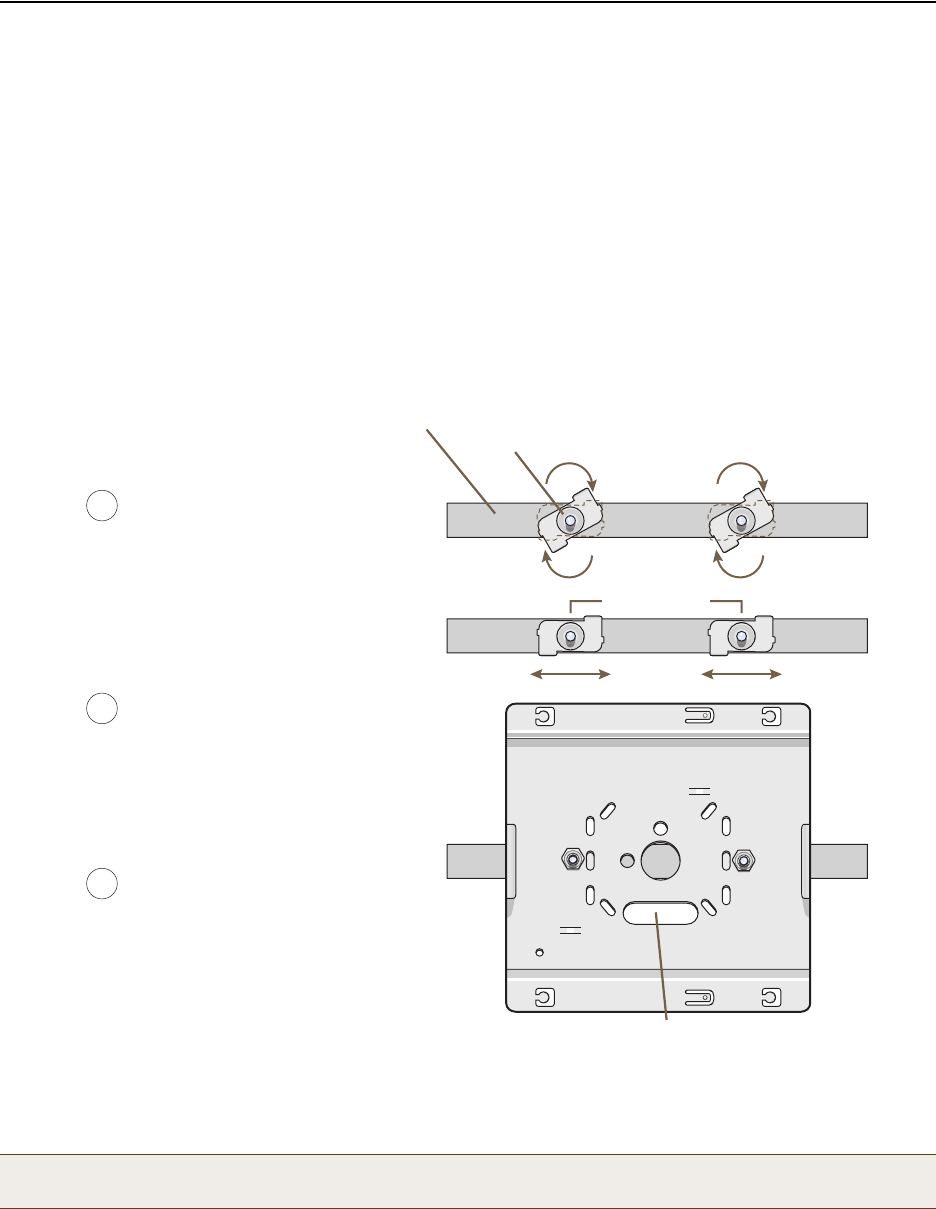
To mount the HiveAP 340 to a track in a dropped ceiling, you need the mounting plate, two track clips, and two Keps
nuts that ship as an option with the HiveAP 340. You also need a wrench and—most likely—a ladder.
Nudge the ceiling tiles slightly away from the track to clear some space. Attach the track clips to the ceiling track,
and then fasten the mounting plate to the clips, as shown in Figure 8. When you have the mounting plate in the
correct location, cut or drill a hole in the ceiling through which you can then pass the Ethernet and power cables.
Figure 8 Attaching the Track Clips and Mounting Plate to the Ceiling Track
Attach the HiveAP 340 to the mounting plate and connect the cables, as shown in Figure 9 on page 57.
Note: You can tie the cables to the tie points (small arched strips) on the mounting plate to prevent them from
being pulled out of their connections accidentally.
1
2
Press the track clips against the
ceiling track and swivel them until
they grip the edges of the track.
If necessary, slide one or both of
the clips along the track to position
them at the proper distance to fit
through the holes in the mounting
plate (2 1/4” or 7 cm).
Insert the mounting plate over the
bolts attached to the track clips,
and use the Keps nuts to fasten
the plate to the clips.
Use a wrench to tighten the nuts
firmly to the bolts and secure the
plate to the track.
3Through the oblong opening in the
plate, cut or drill a hole in the ceiling
tile (not shown). Then pass one or
both Ethernet cables through the
hole, and if you plan to supply power
from an AC power source rather than
through PoE, pass the power cable
through as well.
Cut hole in ceiling tile and
feed cables through here.
Mounting Plate
Ceiling Track
Track Clip
(worms’s eye view with ceiling
tiles removed for clarity)
2 1/4 “ (7 cm)
Deployment Guide 57
MOUNTING THE HIVEAP 340
Figure 9 Attaching the HiveAP 340 to the Mounting Plate and Connecting Cables
When done, adjust the ceiling tiles back into their former position.
Locking the HiveAP 340
To lock the HiveAP 340 to the mounting plate, use either a Kensington lock or the lock adapter that is included with
the mounting kit and a small padlock (not included).
To use a Kensington lock, loop the cable attached to the lock around a secure object, insert the T-bar component of
the lock into the device lock slot on the HiveAP, and then turn the key to engage the lock mechanism.
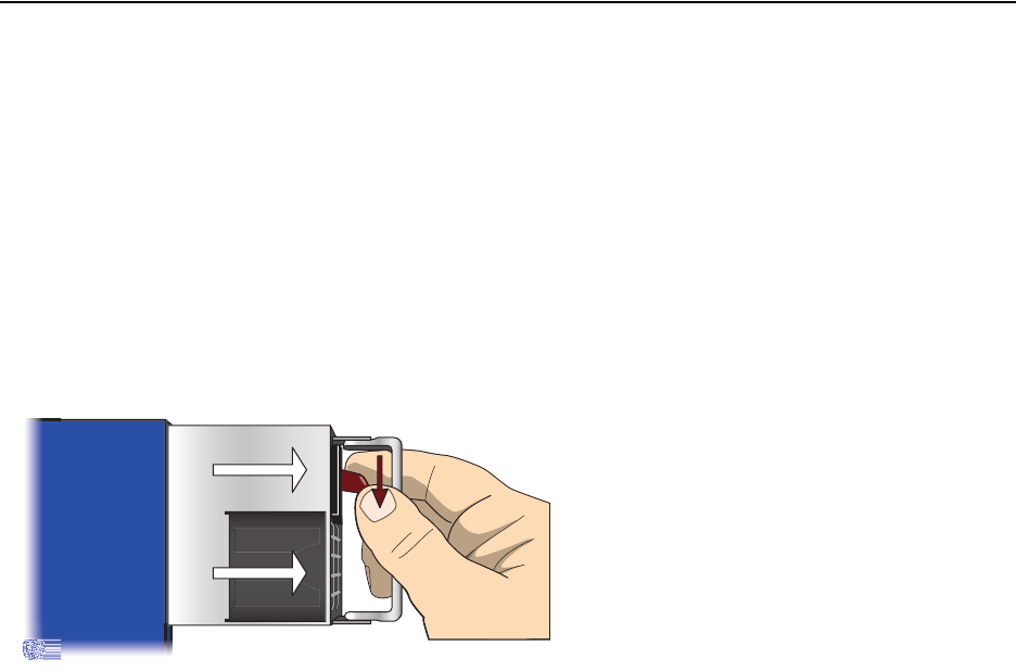
To use the lock adapter :
1. Insert the T-shaped extension on the adapter into the device lock slot, and rotate it clockwise so that the
curved section extends through the slot in the mounting plate (see Figure 10).
Figure 10 Locking the HiveAP 340 to the Mounting Plate
2. Link a padlock through the opening in the adapter and engage the lock to secure the HiveAP 340 to the
mounting plate. The opening is 1/8" (0.3 cm) in diameter at its narrowest.
With the HiveAP 340 upside
down, align its port side with
the edge of the plate.
Push the HiveAP 340 upward,
inserting the four tabs on the
plate into the four slots on the
HiveAP 340.
Slide the HiveAP 340 toward
the port panel, locking the tabs
inside the slots.
Connect the cables to
complete the installation.
4
6
7
5Tab
inside
slot.
Tab
locked in
place.
Mounting Plate
HiveAP 340 (shown as transparent for clairty)
Tab
Slot
(side view)
Mounting Plate
HiveAP 340
Ceiling
Cables pass through the hole in
the mounting plate and ceiling
5 GHz (A)
5 GHz (B)5 GHz (C)
Rotate the
lock adapter
clockwise.
Insert a lock
through the
opening.
HiveAP 340
Mounting Plate
Chapter 4 The HiveAP 340 Platform
58 Aerohive
Surface Mount
You can use the mounting plate to attach the HiveAP 340 to any surface that supports its weight, and to which you
can screw or nail the plate. First, mount the plate to the surface. Then, through one of the two large openings in
the plate, make a hole in the wall so that you can pass the cables through to the HiveAP.
Finally, attach the device to the plate, and connect the cables, as shown in Figure 11.
Figure 11 Mounting the HiveAP on a Wall
Note: You can tie the cables to the tie points on the mounting plate to prevent them from being pulled out of
their connections accidentally.
Mounting Plate
HiveAP 340
Wall
Insert the tabs on the mounting plate
into the slots on the underside of the
HiveAP 340. Then push the HiveAP
340 downward to lock it in place.
With the two wings at the sides of the plate
extending away from the surface, attach the
mounting plate to a secure object such as a
wall, ceiling, post, or beam.
1
3
Note: There are a variety of holes through which you can
screw or nail the plate in place. Choose the two or three
that best suit the object to which you are attaching it.
HiveAP 340
2Cut or drill a hole through one of the
openings in the mounting plate to
pass the cables through to the
HiveAP 340.
Connect the cables to the HiveAP 340.
Depending on the deployment, you might
connect one or two Ethernet cables and a
power cable.
4
(side view)

Deployment Guide 59
DEVICE, POWER, AND ENVIRONMENTAL SPECIFICATIONS
DEVICE, POWER, AND ENVIRONMENTAL SPECIFICATIONS
Understanding the range of specifications for the HiveAP 340 is necessary for optimal deployment and device
operation. The following specifications describe the physical features and hardware components, the power adapter
and PoE (Power over Ethernet) electrical requirements, and the temperature and humidity ranges in which the
device can operate.
Device Specifications
• Chassis dimensions: 8 3/8" W x 1 1/8" H x 8" D (21.3 cm W x 3 cm H x 20.3 cm D)
• Weight: 3 lb. (1.36 kg)
• Antennas: Three omnidirectional 802.11b/g/n antennas, and three omnidirectional 802.11a/n antennas
• Serial port: DB-9 (bits per second: 9600, data bits: 8, parity: none, stop bits: 1, flow control: none)
• Ethernet port: autosensing 10/100Base-T/TX Mbps, with IEEE 802.3af-compliant PoE (Power over Ethernet)
Power Specifications
• AC/DC power adapter:
• Input:100 – 240 VAC
• Output: 48V/0.38A
• PoE nominal voltages:
• Input: 48 V/0.35A
• Output: 48 V/0.625A
• RJ-45 power input pins: Wires 4, 5, 7, 8 or 1, 2, 3, 6
Environmental Specifications
• Operating temperature: -4 to 131 degrees F (-20 to 55 degrees C)
• Storage temperature: -40 to 176 degrees F (-40 to 80 degrees C)
• Relative Humidity: Maximum 95%
Chapter 4 The HiveAP 340 Platform
60 Aerohive
Deployment Guide 61
Chapter 5 The HiveManager Platform
The HiveManager Network Management System provides centralized configuration, monitoring, and reporting for
multiple HiveAPs. The following are a few of the many benefits that a HiveManager offers:
• Simplified installations and management of up to 500 HiveAPs
• Profile-based configurations that simplify the deployment of large numbers of HiveAPs
• Scheduled firmware upgrades on HiveAPs by location
• Exportation of detailed information on HiveAPs for reporting
This chapter covers the following topics related to the HiveManager platform:
•"Product Overview" on page 62
•"Ethernet and Console Ports" on page 63
•"Status LEDs" on page 64
•"Rack Mounting the HiveManager" on page 65
•"Device, Power, and Environmental Specifications" on page 66
Chapter 5 The HiveManager Platform
62 Aerohive
PRODUCT OVERVIEW
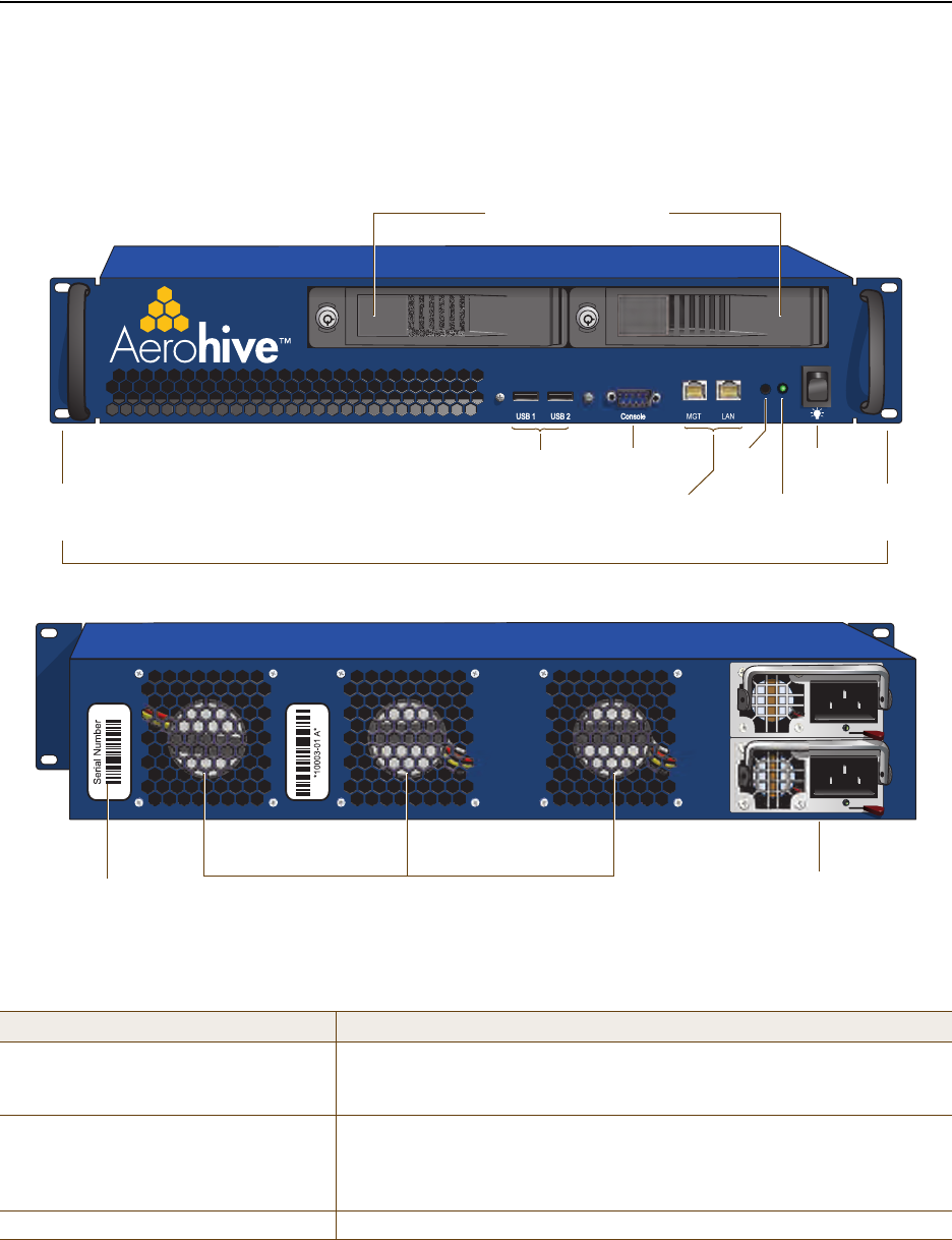
The Aerohive HiveManager is a central management system for configuring and monitoring HiveAPs. You can see its
hardware components in Figure 1 and read a description of each component in Table 1.
Figure 1 HiveManager Hardware Components
Table 1 HiveManager Component Descriptions
Component Description
Mounting Brackets The two mounting brackets allow you to mount the HiveManager in a
standard 19" (48.26 cm) equipment rack. You can also move the brackets
to the rear of the chassis if you need to reverse mount it.
Console Port A male DB-9 serial port to which you can make a console connection using
an RS-232 (or "null modem") cable. The pin assignments are the same as
those on the HiveAP (see "Ethernet and Console Ports" on page 26).
The management station from which you make a serial connection to the
HiveManager must have a VT100 emulation program, such as Tera Term
Pro© (a free terminal emulator) or Hilgraeve Hyperterminal® (provided
with Windows® operating systems). The following are the serial
connection settings: bits per second: 9600, data bits: 8, parity: none,
stop bits: 1, flow control: none. The default login name is admin and the
password is aerohive. After making a connection, you can access the
Linux operating system.
USB
Port
Console
Port Status
LEDs
Mounting
Bracket MGT and LAN
Ethernet Ports Mounting
Bracket
Power
Fan
System
Fans AC Power
Inlet
Serial Number
Label
On/Off
Switch
Front Panel
Rear Panel
Deployment Guide 63
PRODUCT OVERVIEW
Ethernet and Console Ports
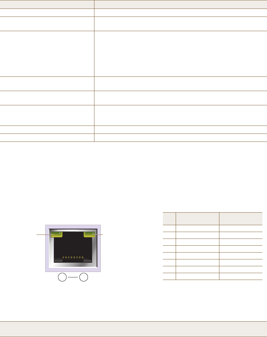
The two 10/100/1000-Mbps Ethernet ports on the HiveManager labeled MGT and LAN use standard RJ-45 connector
pin assignments that follow the TIA/EIA-568-B standard (see Figure 2). They accept standard types of Ethernet
cable—cat3, cat5, cat5e, or cat6. Because the ports have autosensing capabilities, the wiring termination in the
Ethernet cables can be either straight-through or cross-over.
Figure 2 Ethernet Port LEDs and Pin Assignments
USB Port The USB port is reserved for internal use.
Status LEDs The status LEDs convey operational states for the system power and hard
disk drive. For details, see "Status LEDs" on page 64.
MGT and LAN Ethernet Ports The MGT and LAN Ethernet ports are compatible with 10/100/1000-Mbps
connections, automatically negotiate half- and full-duplex mode with the
connecting devices, and support RJ-45 connectors. They are autosensing
and automatically adjust to straight-through and cross-over Ethernet
cables. The two ports allow you to separate traffic between the
HiveManager and its administrators from traffic between the
HiveManager and the HiveAPs it manages.
System Fans The two system fans maintain an optimum operating temperature. Be
sure that air flow through the system fan vents is not obstructed.
Serial Number Label The serial number label contains the FCC compliance stamp, model
number, input power specifications, and serial number for the device.
AC Power Inlet The three-prong AC power inlet is a C14 chassis plug through which you
can connect a HiveManager to a 100 – 240-volt AC power source using the
10-amp/125-volt IEC power cord that ships with the product.
On/Off Switch The on ( | ) and off ( { ) switch controls the power to the HiveManager.
Power Fan The fan that maintains the temperature of the power supply.
Note: The default IP address/netmask for the MGT interface is 192.168.2.10/24. For the LAN interface, the
default IP address/netmask is 192.168.3.10/24. The IP address of the default gateway is 192.168.2.1.
Component Description
(View of an Ethernet port
on the HiveManager)
8 1
Pin Numbers
Pin 10/100Base-T
Data Signal 1000Base-T
Data Signal
1 Transmit + BI_DA+
2 Transmit - BI_DA-
3 Receive + BI_DB+
4 (unused) BI_DC+
5 (unused) BI_DC-
6 Receive - BI_DB-
7 (unused) BI_DD+
8 (unused) BI_DD-
Legend: BI_D = bidirectional
A+/A-, B+/B-, C+/C-, D+/D- = wire pairings
The Ethernet ports are auto-sensing and can automatically adjust to transmit and receive data over straight-through or cross-over
Ethernet connections. For a diagram showing T568A and T568B wiring, see "Ethernet and Console Ports" on page 26.
Link Rate LED
Dark: 10 Mbps
Green: 100 Mbps
Amber: 1000 Mbps
Link Activity LED
Dark: Link is down
Steady amber: Link is up
but inactive
Blinking amber: Link is up
and active
Chapter 5 The HiveManager Platform
64 Aerohive
The pin assignments in the male DB-9 console port follow the EIA (Electronic Industries Alliance) RS-232 standard. To
make a serial connection between your management system and the console port on the HiveManager, you can use a
null modem serial cable, use another serial cable that complies with the RS-232 standard, or refer to the
pin-to-signal mapping shown in Figure 3 to make your own serial cable. Connect one end of the cable to the console
port on the HiveManager and the other end to the serial (or COM) port on your management system. The
management system must have a VT100 terminal emulation program, such as Tera Term Pro© (a free terminal
emulator) or Hilgraeve Hyperterminal® (provided with Windows® operating systems).
Figure 3 Console Port Pin Assignments
The serial connection settings are as follows:
• Bits per second: 9600
• Data bits: 8
• Parity: none
•Stop bits: 1
• Flow control: none
Status LEDs
The two status LEDs on the front of the HiveManager indicate various states of activity through their color (dark,
green, amber) and illumination patterns (steady glow or blinking). The meanings of the various color + illumination
patterns for each LED are shown in Figure 4.
Figure 4 Status LEDs
12 3 45
6 7 8 9
Pin Signal Direction
1 DCD (Data Carrier Detect) (unused)
2 RXD (Received Data) Input
3 TXD (Transmitted Data) Output
4 DTR (Data Terminal Ready) (unused)
5 Ground Ground
6 DSR (Data Set Ready) (unused)
7 RTS (Request to Send) (unused)
8 CTS (Clear to Send) (unused)
9 RI (Ring Indicator) (unused)
Male DB-9 Console Port
(View of the console port
on the HiveManager) The above pin assignments show a DTE configuration for a
DB-9 connector complying with the RS-232 standard. Because
this is a console port, only pins 2, 3, and 5 need be used.
RS-232 Standard Pin Assignments
System Power
Dark: No power
Steady illumination: Powered on
Hard Disk Drive
Dark: Idle
Blinking: Active
Deployment Guide 65
RACK MOUNTING THE HIVEMANAGER
RACK MOUNTING THE HIVEMANAGER
You can mount the HiveManager in a standard 19" (48 cm) equipment rack with two rack screws—typically 3/4",
1/2", or 3/8" long with 10-32 threads. The HiveManager ships with mounting brackets already attached to its left
and right sides near the front panel (see Figure 1 on page 62). In this position, you can front mount the HiveManager
as shown in Figure 5. Depending on the layout of your equipment rack, you might need to mount the HiveManager in
reverse. To do that, move the brackets to the left and right sides near the rear before mounting it.
Figure 5 Mounting the HiveManager in an Equipment Rack
1. Position the HiveManager so that the holes in the mounting brackets align with two mounting holes in the
equipment rack rails.
2. Insert a screw through a washer, the hole in one of the mounting brackets, and a hole in the rail.
3. Tighten the screw until it is secure.
4. Repeat steps 2 and 3 to secure the other side of the HiveManager to the rack.
Washer Rack
Screw
Mounting
Bracket
Rack Rails

Chapter 5 The HiveManager Platform
66 Aerohive
DEVICE, POWER, AND ENVIRONMENTAL SPECIFICATIONS
Understanding the range of specifications for the HiveManager is necessary for optimal deployment and operation of
the device. The following specifications describe the physical features and hardware components, the electrical
requirements for the power supply and cord, and the temperature and humidity ranges in which the device can
operate.
Device Specifications
• Form factor: 1U rack-mountable device
• Chassis dimensions: 16 13/16" W x 1 3/4" H x 15 13/16" D (42.7 cm W x 4.4 cm H x 40.2 cm D)
• Weight: 13.75 lb. (6.24 kg)
• Serial port: male DB-9 RS-232 port (bits per second:9600, data bits: 8, parity: none, stop bits: 1, flow control:
none)
• USB port: standard Type A USB 2.0 port
• Ethernet ports: MGT and LAN — autosensing 10/100/1000Base-T Mbps
Power Specifications
• ATX (Advanced Technology Extended) autoswitching power supply with PFC (power factor corrector):
• Input: 100 – 240 VAC
• Output: 250 watts
• Power supply cord: Standard three conductor SVT 18AWG cord with an NEMA5-15P three-prong male plug and
three-pin socket
Environmental Specifications
• Operating temperature: 32 to 140 degrees F (0 to 60 degrees C)
• Storage temperature: -4 to 176 degrees F (-20 to 80 degrees C)
• Relative Humidity: 10% – 90% (noncondensing)
Deployment Guide 67
Chapter 6 The High Capacity HiveManager
Platform
The High Capacity HiveManager is a management system that provides centralized configuration, monitoring, and
reporting for multiple HiveAPs. The following are a few of the many benefits that a HiveManager offers:
• Simplified installations and management of up to 5000 HiveAPs
• Profile-based configurations that simplify the deployment of large numbers of HiveAPs
• Scheduled firmware upgrades on HiveAPs by location
• Exportation of detailed information on HiveAPs for reporting
• Hot swappable power supplies
• Cold swappable hard disk drives
This chapter covers the following topics related to the High Capacity HiveManager platform:
•"Product Overview" on page 68
•"Rack Mounting the High Capacity HiveManager" on page 70
•"Replacing Power Supplies" on page 73
•"Replacing Hard Disk Drives" on page 74
•"Device, Power, and Environmental Specifications" on page 75
Chapter 6 The High Capacity HiveManager Platform
68 Aerohive
PRODUCT OVERVIEW
The Aerohive High Capacity HiveManager is a central management system for configuring and monitoring HiveAPs.
You can see its hardware components in Figure 1 and read a description of each component in Table 1.
Figure 1 High Capacity HiveManager Hardware Components
Table 1 High Capacity HiveManager Component Descriptions
Component Description
Hard Disk Drive Trays The two hard disk drive trays contain first-level RAID (Redundant Array of
Independent Drives) mirrored hard disk drives to provide fault tolerance,
data reliability, and increased performance.
Front Mounting Brackets When used with the rack mounting kit, the two front mounting brackets
allow you to mount the High Capacity HiveManager in a standard 19"
(48.26 cm) equipment rack. For rack mounting instructions, see "Rack
Mounting the High Capacity HiveManager" on page 70.
USB Ports The USB ports are reserved for internal use.
USB
Ports Console
Port
Power
LED
MGT and LAN
Ethernet Ports
System FansSerial Number
Label
Front Panel
Rear Panel
Front
Mounting
Bracket
Power
Switch
Hard Disk Drive Trays
Reset
Button Front
Mounting
Bracket
Dual AC Power
Supplies

Deployment Guide 69
PRODUCT OVERVIEW
Console Port A male DB-9 serial port to which you can make a console connection using
an RS-232 (or "null modem") cable. The pin assignments are the same as
those on the HiveManager and on the HiveAP (see "Ethernet and Console
Ports" on page 26).
The management station from which you make a serial connection to the
HiveManager must have a VT100 emulation program, such as Tera Term
Pro© (a free terminal emulator) or Hilgraeve Hyperterminal® (provided
with Windows® operating systems). The following are the serial
connection settings: bits per second: 9600, data bits: 8, parity: none,
stop bits: 1, flow control: none. The default login name is admin and the
password is aerohive. After making a connection, you can access the
Linux operating system.
MGT and LAN Ethernet Ports The MGT and LAN Ethernet ports are compatible with 10/100/1000-Mbps
connections, automatically negotiate half- and full-duplex mode with the
connecting devices, and support RJ-45 connectors. They are autosensing
and automatically adjust to straight-through and cross-over Ethernet
cables. The two ports allow you to separate traffic between the
HiveManager and its administrators from traffic between the
HiveManager and the HiveAPs it manages. The wiring terminates the
same way as that on the standard capacity HiveManager (see "Ethernet
and Console Ports" on page 63).
Reset Button The reset button allows you to reboot the High Capacity HiveManager.
Insert a paper clip, or something similar, into the hole and press the reset
button between 1 and 5 seconds. After releasing the button, the Power
LED goes dark, and then glows steady amber while the software loads and
the system performs a self-test. After the software finishes loading, the
Power LED glows steady green
Power LED The power LED conveys the operational states for the system power:
dark = no power; steady green = powered on.
On/Off Switch The on and off switch controls the power to the HiveManager.
Serial Number Label The serial number label contains the serial number for the device.
System Fans The three system fans maintain an optimum operating temperature. Be
sure that air flow through the system fan vents is not obstructed.
Dual AC Power Supplies There are two power supplies. Each three-prong AC power inlet is a C14
chassis plug through which you can connect the HiveManager to a 100 –
240-volt AC power source using the 10-amp/125-volt IEC power cords that
ship with the product. By cabling each power supply to a different
source, they provide redundancy in the event of a single power failure.
Each power supply has a fan that maintains its temperature. It is
important that nothing obstructs the air flow to these fans so that the
power supplies do not overheat.
Component Description
Chapter 6 The High Capacity HiveManager Platform
70 Aerohive
RACK MOUNTING THE HIGH CAPACITY HIVEMANAGER
Use the rack mounting kit to mount the High Capacity HiveManager in a standard 19" (48 cm) equipment rack. The
rack mounting kit contains the following items:
• (2) slide sets (each consisting of an outer slide, inner slide, and chassis rail)
• (2) rear mounting brackets
•(4) bar nuts
•(4) locator pins
• (6) slot-head machine screws with 8-32 threads – for attaching the mounting brackets to the outer slides
• (14) cross-head machine screws with 10-32 threads – for attaching the chassis rails to the HiveManager, and
the front and the rear mounting brackets to equipment rack rails with tapped holes or to the enclosed bar
nuts when the rack rails have round holes
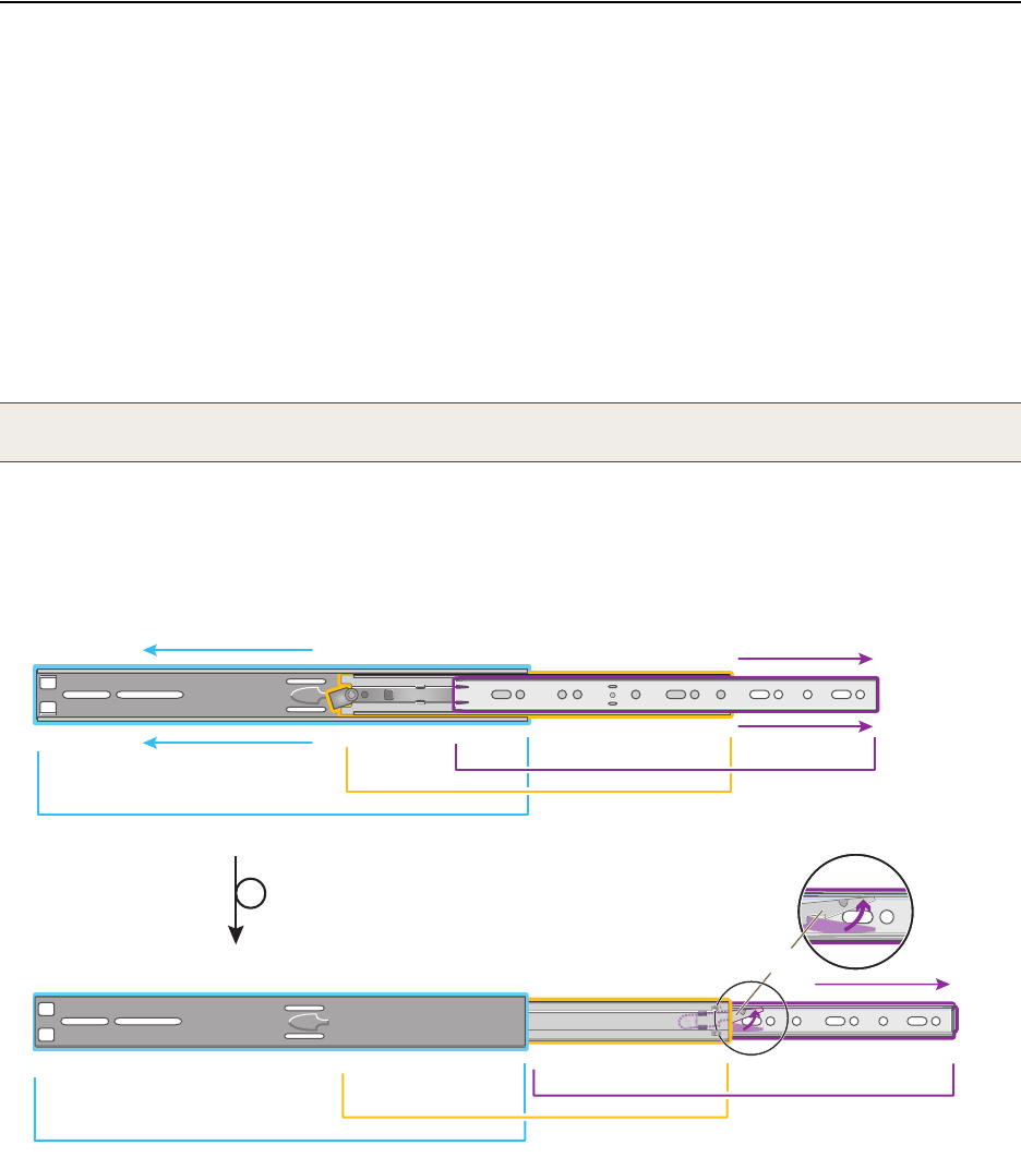
1. After checking that the mounting kit contains the above parts, separate the chassis rails from each slide set, as
shown in Figure 2.
Figure 2 Separating the Chassis Rail from the Nested Slides
2. Position one of the chassis rails so that the slide stop is near the HiveManager mounting bracket near the front
panel and the front and rear holes in the chassis rail align with the holes in the side of the HiveManager. Use
three of the cross-head screws to secure the chassis rail to the HiveManager chassis as shown in Figure 3 on
page 71.
Note: Because of the weight of the device (34 lb./ 15.42 kg without rails) , two people are required to rack
mount it safely.
Outer Slide
Inner Slide
Chassis Rail
Extend the telescoping pieces of the
slide set to the left and right.
Outer Slide
Inner Slide
Chassis Rail
Swivel the catch to release the chassis rail,
and then slide it compleletely away from the
nested slides.
Turn over.
Catch
Deployment Guide 71
RACK MOUNTING THE HIGH CAPACITY HIVEMANAGER
Figure 3 Attaching the Chassis Rail to the HiveManager
3. Secure the other chassis rail to the other side of the HiveManager.
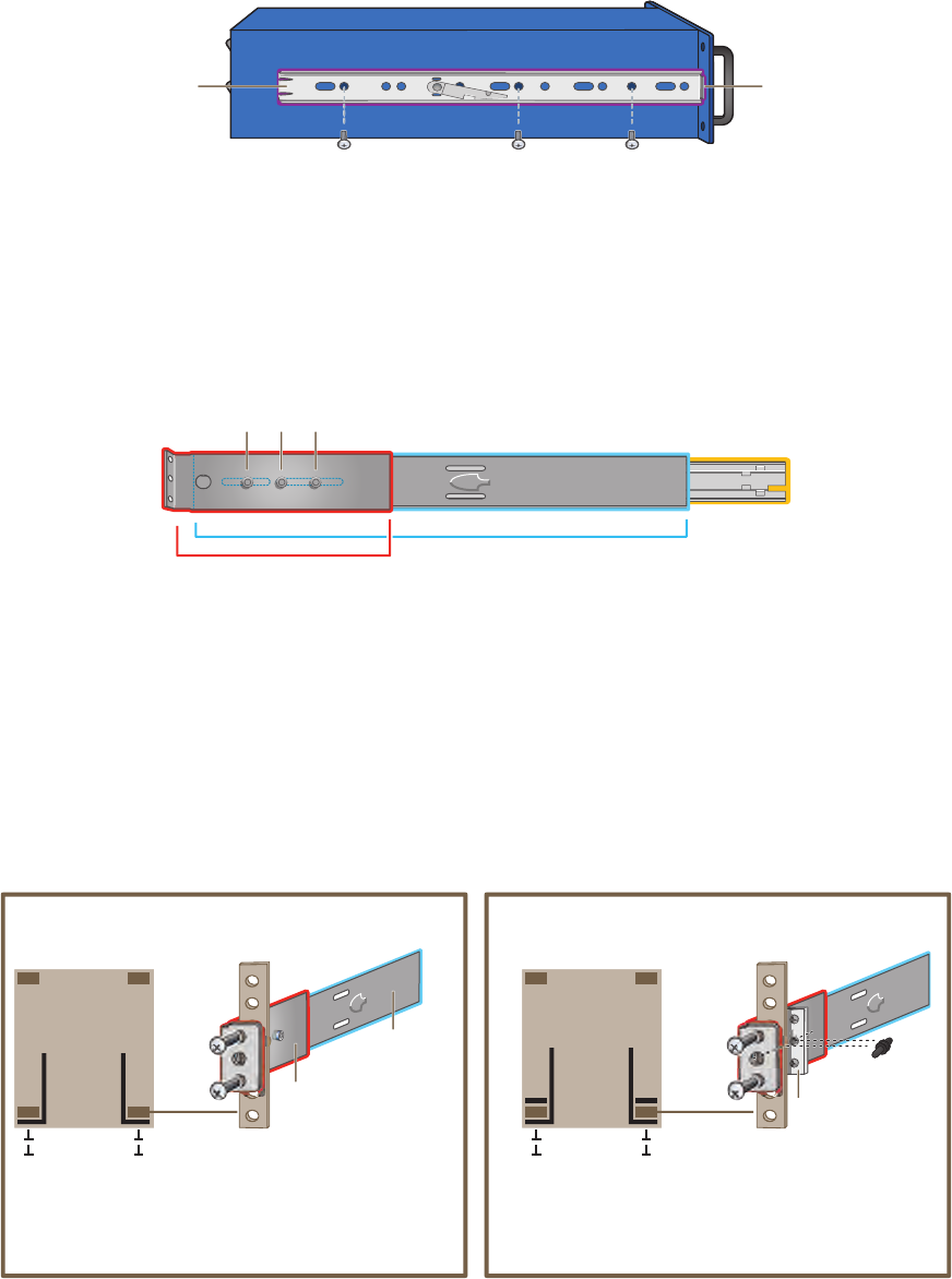
4. Use three slot-head screws to attach the rear mounting bracket to the outer slide. Insert the screws through the
rounded slots in the outer slide into the threaded holes in the bracket and tighten them as shown in Figure 4.
Figure 4 Attaching the Rear Bracket to the Outer Slide
5. Use the remaining three slot-head screws to attach the other rear mounting bracket to the other outer slide.
6. Fasten the rear mounting brackets—and the slides attached to them—to the rear equipment rack rails.
Depending on the type of holes in the equipment rack, use one of the following methods:
• For tapped (threaded) holes, use two screws to fasten the brackets directly to the rack rails. Use the
cross-head screws (with 10-32 threads) if they fit the holes in the rack.
• For round holes, use the cross-head screws to fasten the brackets through the holes in the rack rails to the
bar nuts. You can use the locator pins to help keep the bar nuts aligned to the holes. See Figure 5.
Figure 5 Fastening the Rear Mounting Brackets to the Rack Rails
Place the slide stop
against the front
mounting bracket.
Chassis Rail
cross-head machine screws with 10-32 threads
Outer Slide
Inner Slide
Use three slot-head screws to secure one
of the rear brackets to the outer slide.
Rear Bracket
Rear rail
with round holes
Bar Nut
Locator Pin
For equipment racks with round holes, place a bar nut
on the opposite side of the rear rail from the bracket.
(You can use a locator pin to help keep the nut bar
aligned with the holes.) Then screw the bracket
through the rail into the threaded holes in the bar nut.
Rear Bracket
Rear rail
with tapped holes
Outer Slide
Equipment Rack
(bird’s eye view)
Front
Rear
For equipment racks with tapped holes, screw the rear
brackets to the rear rack rails directly. In this case, you
do not need to use the bar nuts and locator pins that
are provided in the rack mounting kit.
Screws
Brackets
Chapter 6 The High Capacity HiveManager Platform
72 Aerohive
7. From the front of the equipment rack, guide the chassis rails on the sides of the HiveManager into the inner
slides. Then push the HiveManager into the rack until the front mounting brackets are flush against the front
rack rails.
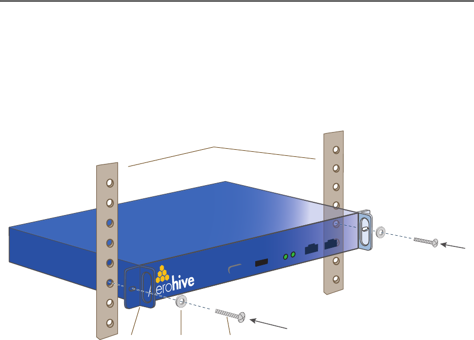
8. Using four screws—two for each of the front brackets—fasten the HiveManager to the equipment rack as shown
in Figure 6. If the rack has round holes, use the two remaining nut bars (and locator pins) and thread the screws
through the rack rails into them.
Figure 6 Mounting the HiveManager in an Equipment Rack
The HiveManager is now securely mounted to the front and rear rails of the equipment rack.
Screws
Front
Mounting Bracket
Rack Rails
Outer Slide
Inner Slide (over
the chassis rail)
Rear
Mounting Bracket
Screws
Front
Mounting Bracket
Rack Rails
Outer Slide
Inner Slide (over
the chassis rail)
Rear
Mounting Bracket
Deployment Guide 73
REPLACING POWER SUPPLIES
REPLACING POWER SUPPLIES
The high capacity HiveManager has a pair of redundant, hot-swappable power supplies. If one of the power supplies
fails, the other will continue to power the device. When a a power supply fails, a continuous beeping alarm sounds
and the power LED glows amber. To replace the failed power supply, do the following:
1. Disconnect the failed power supply from the power source.
2. Lower the handle to a horizontal position.
3. With your index finger, press the red release lever to the left.
4. While holding the release lever to the left, grip the handle between your thumb and second finger, and pull the
power supply straight out. See Figure 7.
Figure 7 Removing a Power Supply
5. Insert a working power supply into the vacant bay and push it straight in until it is fully seated.
The red release automatically slides back to the right to secure the power supply in place.
6. Connect the power supply to the power source.
Power Supply
Rear of High Capacity HiveManager (bird’s eye view)
Chapter 6 The High Capacity HiveManager Platform
74 Aerohive
REPLACING HARD DISK DRIVES
To provide fault tolerance from disk errors and single disk failure, the high capacity HiveManager uses level 1 RAID
(Redundant Array of Independent Drives) HDDs (hard disk drives). Each HDD holds identical data, the data that is
written to one disk being mirrored to the other. The lower LEDs on the front of each HDD flash in unison to indicate
that they are writing data to memory. The upper LEDs indicate that they have power. See Figure 8.
Figure 8 Hard Disk Drive LEDs
If you notice that only one of the lower LEDs is flashing while the other is dark, then there is a HDD failure. Although
the HiveManager can continue with just one operational HDD, you should replace the faulty HDD soon.
1. Turn off the HiveManager.
2. Unlock the HDD tray door for the disk that you want to replace.
3. Pull the tab on the left side of the door, and open the door, swivelling it on the hinge along its right side.
As you open the door, the HDD tray automatically extends.
4. Remove the failed HDD and insert a replacement
5. Close the door and lock it again.
6. Connect a serial cable to the console port
7. Connect one end of an RS-232 serial cable to the male DB-9 console port on the HiveManager and other end to
the serial port (or COM port) on your management system.
8. Start a serial connection as explained in "Changing Network Settings" on page 79.
9. Turn on the HiveManager.
10. While it is booting up, press and hold down the CTRL+A keys until the utility console appears.
11. From the main menu, select Manage Arrays. (An array is the logical representation of a physical HDD unit.)
12. From the list of arrays, select the one that you want to rebuild.
13. Press CTRL+R to rebuild it.
The rebuild process takes about 30 minutes. When done, the utility console notifies you with a message.
14. Confirm that the process is complete.
The HiveManager continues booting up with the new HDD replacement in operation.
Note: HiveManager HDDs are not hot swappable. You must turn off the power before replacing a HDD.
Note: The replacement disk drive must be new or, if it has been used, there must not be a root file system on
it. Also, it must be the same size as or bigger than the other disk drive.
Upper LED: Power Status
(Illuminates when the
HDD first receives power)
Lower LED: HDD Activity
(Illuminates when writing
to memory)
Hard Disk Drive TrayLock
Tab

Deployment Guide 75
DEVICE, POWER, AND ENVIRONMENTAL SPECIFICATIONS
DEVICE, POWER, AND ENVIRONMENTAL SPECIFICATIONS
Understanding the range of specifications for the high capacity HiveManager is necessary for the optimal
deployment and operation of the device. The following specifications describe the physical features and hardware
components, the electrical requirements for the power supply and cord, and the temperature and humidity ranges
in which the device can operate.
Device Specifications
• Form factor: 2U rack-mountable device
• Chassis dimensions: 16 13/16" W x 3 1/2" H x 17" D (42.7 cm W x 8.9 cm H x 43.2 cm D)
• Weight: 34 lb. (15.42 kg)
• Serial port: male DB-9 RS-232 port (bits per second:9600, data bits: 8, parity: none, stop bits: 1, flow control:
none)
• USB port: standard Type A USB 2.0 port
• Ethernet ports: MGT and LAN — autosensing 10/100/1000Base-T Mbps
Power Specifications
• Redundant ATX (Advanced Technology Extended) autoswitching power supplies with PFC (power factor
corrector):
• Input: 100 – 240 VAC
• Output: 700 watts
• Power supply cords: Standard three conductor SVT 18AWG cords with an NEMA5-15P three-prong male plug and
three-pin socket
Environmental Specifications
• Operating temperature: 32 to 140 degrees F (0 to 60 degrees C)
• Storage temperature: -4 to 176 degrees F (-20 to 80 degrees C)
• Relative Humidity: 10% – 90% (noncondensing)
Chapter 6 The High Capacity HiveManager Platform
76 Aerohive
Deployment Guide 77
Chapter 7 Using HiveManager
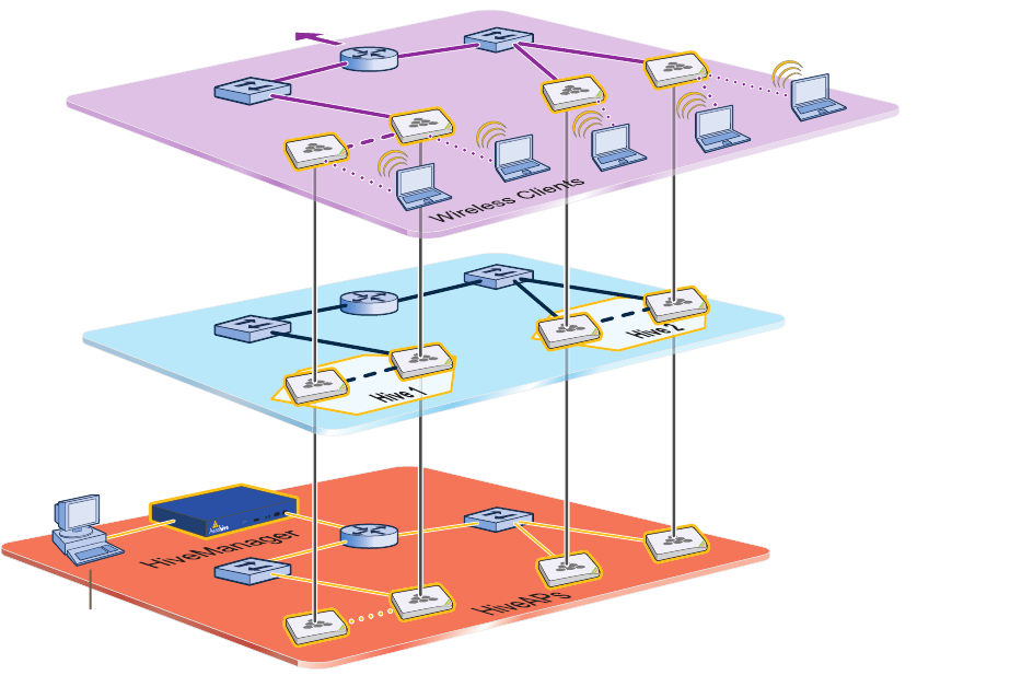
You can conceptualize the Aerohive cooperative control architecture as consisting of three broad planes of
communication. On the data plane, wireless clients gain network access by forming associations with HiveAPs. On
the control plane, HiveAPs communicate with each other to coordinate functions such as best-path forwarding, fast
roaming, and automatic RF (radio frequency) management. On the management plane, HiveManager provides
centralized configuration, monitoring, and reporting of multiple HiveAPs. These three planes are shown in Figure 1.
Figure 1 Three Communication Planes in the Aerohive Cooperative Control Architecture
As you can see in Figure 1, HiveManager operates solely on the management plane. Any loss of connectivity between
HiveManager and the HiveAPs it manages only affects HiveAP manageability; such a loss has no impact on
communications occurring on the control and data planes.
The management
plane is the logical division of
administrative traffic relating to the
configuration and monitoring of HiveAPs. From a
management system, an admin can use the HiveManager to
configure, maintain, and monitor multiple HiveAPs, essentially coordi-
nating the control and data planes from a single, central location.
Data Plane
Control Plane
Management Plane
The data plane
is the logical division of
wireless client traffic (user data)
traversing a wireless-to-wired LAN. Traffic
in the data plane follows optimal paths
that various mechanisms in the control
plane determine.
The control plane is
the logical division of traffic that
hive members use to collaborate on how
best to forward user data, coordinate
radio frequencies, and provide layer-2
and layer-3 roaming capabilities with
each other.
To the wired
network ...
Management
System
Chapter 7 Using HiveManager
78 Aerohive
This chapter explains how to do the following basic tasks:
• Use the console port to change the network settings for the MGT and LAN interfaces
• Power on HiveManager and connect it to a network
• Make an HTTPS connection from your management system to HiveManager and log in to the GUI
It then introduces the HiveManager GUI and includes a summary of the configuration workflow. Finally, the chapter
concludes with procedures for updating HiveManager software and HiveAP firmware. The sections are as follows:
•"Installing and Connecting to the HiveManager GUI" on page 79
•"Introduction to the HiveManager GUI" on page 82
•"Cloning Configurations" on page 83
•"Multiselecting" on page 83
•"Sorting Displayed Data" on page 84
•"HiveManager Configuration Workflow" on page 85
•"Updating Software on HiveManager" on page 86
•"Updating HiveOS Firmware" on page 87
•"Updating HiveAPs in a Mesh Environment" on page 88
Deployment Guide 79
INSTALLING AND CONNECTING TO THE HIVEMANAGER GUI
INSTALLING AND CONNECTING TO THE HIVEMANAGER GUI
To begin using the HiveManager GUI, you must first configure the MGT interface to be accessible on the network,
cable HiveManager and your management system (that is, your computer) to the network, and then make an HTTP
connection from your system to the MGT interface and download the GUI application.
Besides HiveManager and your management system, you need two or three Ethernet cables and a serial cable (or
"null modem"). The Ethernet cables can be standard cat3, cat5, cat5e, or cat6 cables with T568A or T568B
terminations and RJ-45 connectors. The serial cable must comply with the RS-232 standard and terminate on the
HiveManager end with a female DB-9 connector. (For more details, see "Ethernet and Console Ports" on page 63.)
The GUI requirements for the management system are as follows:
• Minimum screen resolution of 1024 x 768 pixels
• Standard browser—Aerohive recommends Internet Explorer v7.0 or Mozilla Firefox v2.0.0 or later—with Flash
v9.0 or later, which is required for viewing charts with dynamically updated HiveAP alarms and wireless client
data
Your management system also needs a VT100 terminal emulation program, such as Tera Term Pro© (a free terminal
emulator) or Hilgraeve Hyperterminal® (provided with Windows® operating systems).
Changing Network Settings
To connect HiveManager to the network, you must first set the IP address/netmask of its MGT interface so that it is
in the subnet to which you plan to cable it. To do this, you can use the startup wizard that is available through the
console port.
1. Connect the power cable to a 100 – 240-volt power source, and turn on HiveManager. The power switch is on the
back panel of the device.
2. Connect one end of an RS-232 serial cable to the serial port (or COM port) on your management system.
3. Connect the other end of the cable to the male DB-9 console port on HiveManager.
4. On your management system, run a VT100 emulation program using the following settings:
• Bits per second (baud rate): 9600
• Data bits: 8
• Parity: none
•Stop bits: 1
• Flow control: none
5. Log in by entering the default user name (admin) and password (aerohive).
6. The HiveManager CLI shell launches and offers several options. To change network settings, enter 1
7. Follow the instructions to configure the IP address and netmask for the MGT (and LAN) interfaces, as well as the
default gateway, host name and domain name of HiveManager, and its primary DNS server.
When deciding to use one interface (MGT) or both (MGT and LAN), keep in mind that there are two main types
of traffic to and from HiveManager:
• HiveManager management traffic for admin access and SCP (Secure Copy) uploads
Note: HiveManager has two Ethernet interfaces—MGT and LAN. You can put just the MGT interface on the
network and use it for all types of traffic, or you can use both interfaces—which must be in different
subnets—and separate HiveManager management traffic (MGT) from HiveAP management traffic (LAN).
Note: The default IP address/netmask for the MGT interface is 192.168.2.10/24. For the LAN interface, it is
192.168.3.10/24. The default gateway IP address is 192.168.2.1. If you only use the MGT interface,
change the LAN interface network settings to 0.0.0.0/0. Do not assign it an IP address and netmask.
Chapter 7 Using HiveManager
80 Aerohive
• HiveAP management traffic for CAPWAP, SNMP monitoring and notifications, and SCP configuration, captive
web portal file, and HiveOS firmware uploads to managed HiveAPs
When you enable both interfaces, HiveManager management traffic uses the MGT interface while HiveAP
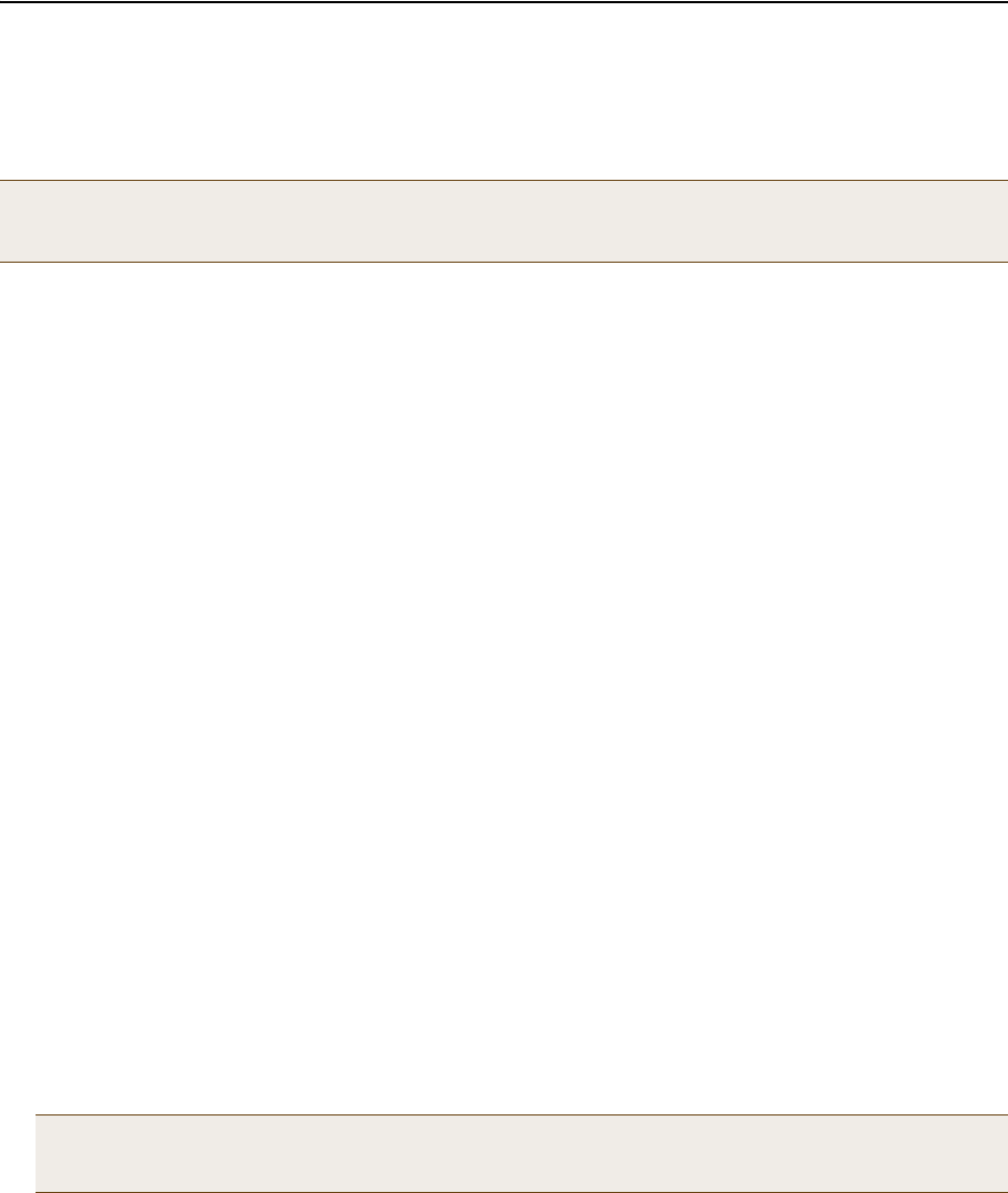
management traffic uses the LAN interface, as shown in Figure 2.
Figure 2 Using Both MGT and LAN Interfaces
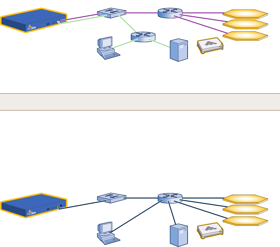
When only the MGT interface is enabled, both types of management traffic use it. A possible drawback to this
approach is that the two types of management traffic cannot be separated into two different networks. For
example, if you have an existing management network, you would not be able to use it for HiveManager
management traffic. Both HiveManager and HiveAP management traffic would need to flow on the operational
network because HiveManager would need to communicate with the HiveAPs from its MGT interface (see
Figure 3). However, if the separation of both types of traffic is not an issue, then using just the MGT interface is
a simple approach to consider.
Figure 3 Using Just the MGT Interface
8. After you finish configuring the network settings, return to the main menu, and reboot the HiveManager
appliance by entering 5 (5 Reboot HM Appliance).
You can now disconnect the serial cable.
Note: To set static routes after you log in to the GUI, click HM Admin > HiveManager Settings > Routing >
Add, set the destination IP address/netmask and gateway, and then click Apply.
MGT
10.1.2.8/24
LAN
10.1.1.8/24
Switch Router Hives in different subnets
Router
10.1.3.0/24
10.1.4.0/24
10.1.5.0/24
10.1.1.1
10.1.2.1
Admin
10.1.7.34 SCP Server
10.1.6.12
HiveManager
Each hive contains
multiple HiveAPs.
Static Routes: HiveManager sends traffic destined for 10.1.6.0/24 to 10.1.2.1.
HiveManager sends traffic destined for 10.1.7.0/24 to 10.1.2.1.
Default Gateway: 10.1.1.1 (HiveManager sends traffic here when there are no specific routes to a destination.)
MGT
10.1.1.8/24
LAN
0.0.0.0/0 Switch Router Hives in different subnets
10.1.3.0/24
10.1.4.0/24
10.1.5.0/24
10.1.1.1
Admin
10.1.7.34 SCP Server
10.1.6.12
HiveManager
Each hive contains
multiple HiveAPs.
Default Gateway: 10.1.1.1 (HiveManager sends all traffic to the default gateway.)
Deployment Guide 81
INSTALLING AND CONNECTING TO THE HIVEMANAGER GUI
Connecting to the GUI through the MGT Interface
1. Connect Ethernet cables from the MGT interface and LAN interface—if you are using it—to the network.
2. Connect an Ethernet cable from your management system to the network so that you can make an HTTPS
connection to the IP address that you set for the MGT interface.
3. Open a web browser and enter the IP address of the MGT interface in the address field. For example, if you
changed the IP address to 10.1.1.8, enter this in the address field: https://10.1.1.8
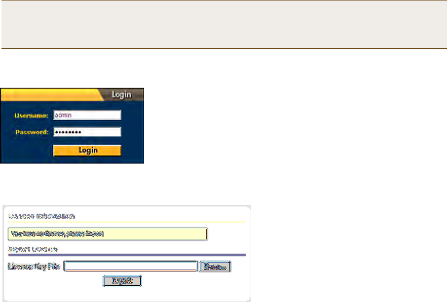
A login prompt appears.
4. Type the default user name (admin) and password (aerohive) in the login fields, and then click Login.
5. If prompted to enter a license key, click Browse, navigate to and select the text file containing the license key
that Aerohive provided when HiveManager was purchased, and then click OK.
You are now logged in to the HiveManager GUI. After logging in, you can check details about the license you
installed on the HM Admin > License Management page.
Note: If you ever forget the IP address of the MGT interface and cannot make an HTTP connection to
HiveManager, make a serial connection to its console port and enter this command: ifconfig . The
output displays data about the MGT interface (internally called "eth0"), including its IP address. The
serial connection settings are explained in "Changing Network Settings" on page 79.
Chapter 7 Using HiveManager
82 Aerohive
INTRODUCTION TO THE HIVEMANAGER GUI
Using the HiveManager GUI, you can set up the configurations needed to deploy, manage, and monitor large
numbers of HiveAPs. The configuration workflow is described in "HiveManager Configuration Workflow" on page 85.
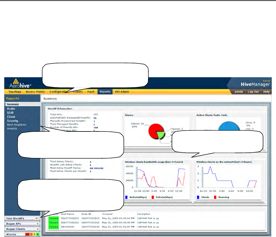
The GUI consists of several important sections, which are shown in Figure 4.
Figure 4 Important Sections of the HiveManager GUI
Some convenient aspects that the HiveManager GUI offers are the ability to clone configurations, apply
configurations to multiple HiveAPs at once, and sort displayed information. Brief overviews of these functions are
presented in the following sections.
Main Panel: The main panel contains
the windows in which you set and view
various parameters.
Notifications: HiveManager displays a
summary of new HiveAPs, rogue APs, rogue
clients, and alarms detected on managed
HiveAPs here. Clicking a displayed number
opens the relevant page with more details.
Menu Bar: The items in the menu bar open
the major sections of the GUI. You can then
use the navigation tree to navigate to more
specific topics within the selected section.
Navigation Tree: The navigation tree contains
all the topics within the GUI section that you
chose in the menu bar. Items you select in the
navigation tree appear in the main panel.
Deployment Guide 83
INTRODUCTION TO THE HIVEMANAGER GUI
Cloning Configurations
When you need to configure multiple similar objects, you can save time by configuring just the first object, cloning
it, and then making slight modifications to the subsequent objects. With this approach, you can avoid re-entering
repeated data.
Figure 5 Cloning a Hive
Multiselecting
You can select multiple objects to make the same modifications or perform the same operation to all of them at
once.
Figure 6 Selecting Multiple New HiveAPs
1. Select
2. Click
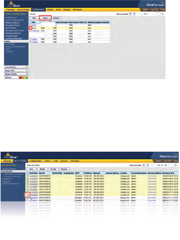
To clone an object, select it in an open window, and then click the Clone button.
Retain the settings you want to keep, and modify those you want to change.
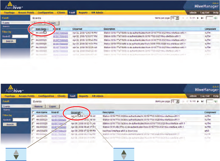
Here, you use the shift-click multiselection method to select a set of the topmost eight HiveAPs in
the list; that is, you select the check box for the top HiveAP and hold down the SHIFT key while
selecting the check box for the eighth HiveAP from the top.
Select the check boxes to select multiple noncontiguous objects, or shift-click to select check
boxes for multiple contiguous objects.
Then click Accept to accept all the selected HiveAPs for HiveManager management, or click
the Modify button to configure them with the same settings.
Chapter 7 Using HiveManager
84 Aerohive
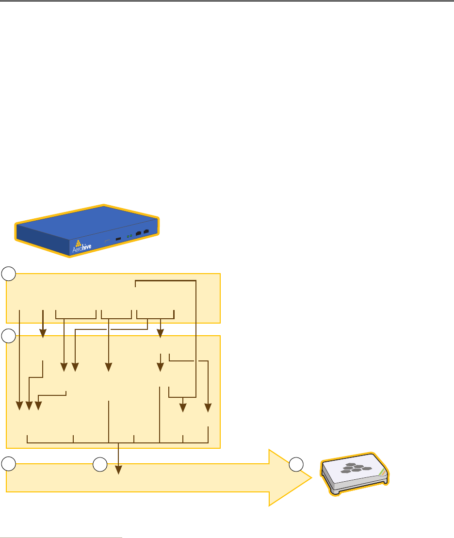
Sorting Displayed Data
You can control how the GUI displays data in the main panel by clicking a column header. This causes the displayed
content to reorder itself alphanumerically or chronologically in either ascending or descending order. Clicking the
header a second time reverses the order in which the data is displayed.
Figure 7 Sorting Event Log Entries by HiveAP Host Name and then Chronologically
Indicates that the list appears in
descending order from the top Indicates that the list appears in
ascending order from the bottom
By default, displayed objects are sorted alphanumerically from the top by name. If you click the
name again, the order is reversed; that is, the objects are ordered alphanumerically from the bottom.
By clicking the heading of a column, you can reorder the display of objects either alphanumerically or
chronologically, depending on the content of the selected column. Here you reorder the data chronologically.
Deployment Guide 85
HIVEMANAGER CONFIGURATION WORKFLOW
HIVEMANAGER CONFIGURATION WORKFLOW
Assuming that you have already installed your HiveAPs, uploaded maps (see "Setting Up Topology Maps" on page 91),
accepted the HiveAPs for management, and decided on the features and settings you want to use, you are now
ready to start configuring the HiveAPs through HiveManager1. You can configure numerous objects, some of which
might need to reference other objects. An efficient configuration strategy is to first define any objects that you will
later need to use when configuring others. The typical workflow, shown in Figure 8, proceeds like this:
1. Define network objects. You can then reference them when defining other parts of the configuration. If you do
not plan to use network objects, you can skip this step.
2. Configure various features.
3. Define radio profiles (or use default settings).
4 and 5. Compile the features from step 2 into a WLAN policy, assign the radio profiles and WLAN policy to one or
more HiveAPs, and then push the configurations to the physical devices on the network.
Figure 8 Configuration Workflow
1. When HiveAPs are in the same subnet as HiveManager, they can use CAPWAP (Control and Provisioning of Wireless Access Points)
to discover HiveManager on the network. CAPWAP works within a layer-2 broadcast domain and is enabled by default on all
HiveAPs. If the HiveAPs and HiveManager are in different subnets, then you can use one of several approaches to enable
HiveAPs to connect to HiveManager. For information about these options, see "How HiveAPs Connect to HiveManager" on
page 95.
MAC Filters
User
Profiles
SSIDs
Mgt
Services AAA
Settings
Radio Profiles WLAN Policy
Hive
HiveManager
Managed
HiveAP
1. If you need to reference network objects in another part of the
configuration, you must define them first. Otherwise, this step
is unnecessary.
4. Compose a WLAN policy by referencing items set in Step 2.
2. Use default settings or configure new settings for various
features that, when combined, constitute a WLAN policy:
• Mobility policies
• Firewall policies
• QoS traffic classification and marking
•MAC Filters
•SSIDs
• User profiles
• Management services (DNS, NTP, SNMP, syslog, location)
• AAA settings (for user authentication using IEEE 802.1X)
• Wireless IDS policy
•Hive
1
2
34 5
QoS Traffic
Classification
and Marking 3. Use default settings or define one or more radio profiles.
5. Apply the WLAN policy and radio profiles to one or more
HiveAPs, and then push the configuration to the physical
devices across the network.
MAC
Addresses
Network Objects:
MAC
OUIs
Services
IP
Addresses
Mobility
Policies
IDS
Policy
VLANs
Firewall
Policies

Chapter 7 Using HiveManager
86 Aerohive
UPDATING SOFTWARE ON HIVEMANAGER
You can update the software running on HiveManager from either a local directory on your management system or
an SCP (Secure Copy) server. If you download an image and save it to a local directory, you can load it from there. If
you save the image to an SCP server, you can direct HiveManager to log in and load it from a directory there.
1. If you do not yet have an account on the Aerohive Support portal, send an email request to
(support@aerohive.com) to set one up.
2. When you have login credentials, visit www.aerohive.com/support/login, and log in.
3. Navigate to the software image that you want to load onto HiveManager (Customer Support > Software
Downloads > HiveManager software images) and download the file.
4. Save the HiveManager image file to a local directory or an SCP server.
5. Log in to HiveManager and navigate to HM Admin > HiveManager Operations > Update Software.
6. To load files from a directory on your local management system, choose either Update and clear alarm and
event logs or Full update (to keep existing log entries after the upgrade), and then enter the following:
• File from local host: (select); type the directory path and a file name; or click Browse, navigate to the
software file, and select it.
or
To load a file from an SCP server:
• File from remote server: (select)
• IP Address: Enter the IP address of the SCP server.
• SCP Port: Enter the port number of the SCP server (the default port number for SCP is 22).
• File Path: Enter the directory path and HiveManager software file name. If the file is in the root directory of
the SCP server, you can simply enter the file name.
• User Name: Type a user name with which HiveManager can access the SCP server.
• Password: Type a password with which HiveManager can use to log in securely to the SCP server.
7. To save the new software and reboot HiveManager, click OK.
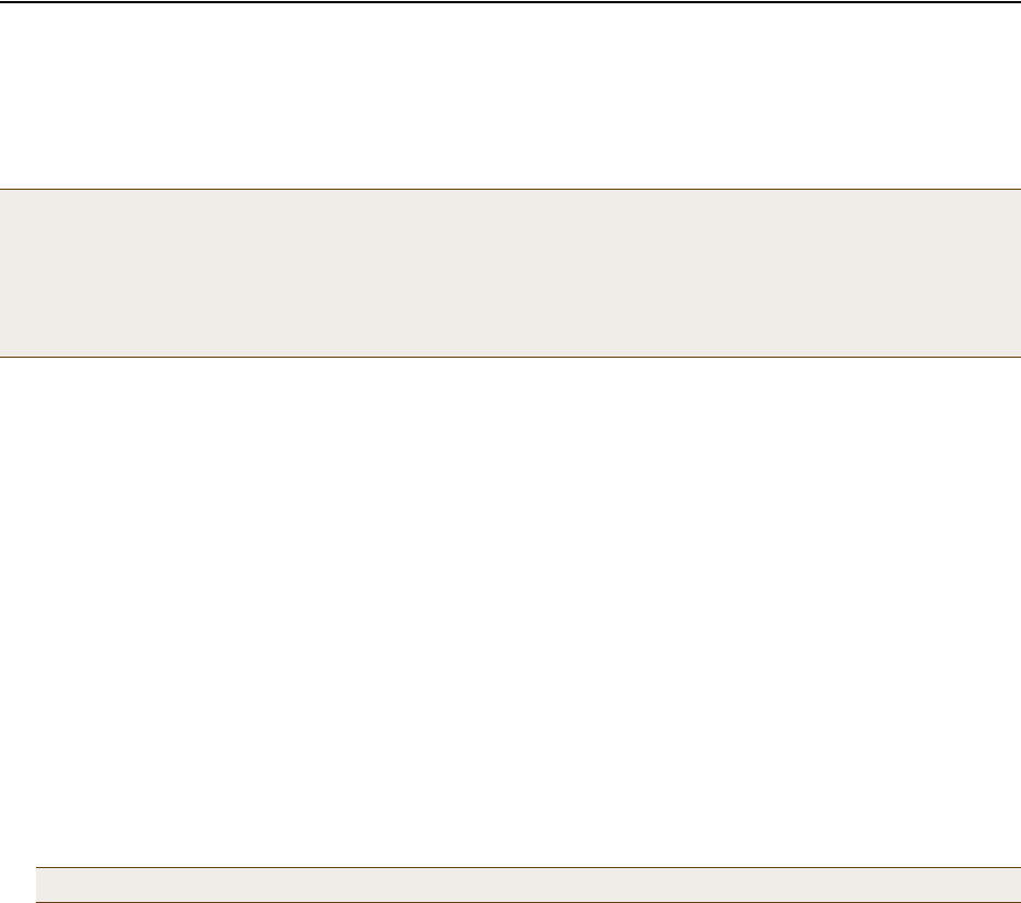
Deployment Guide 87
UPDATING HIVEOS FIRMWARE
UPDATING HIVEOS FIRMWARE
HiveManager makes it easy to update HiveOS firmware running on managed HiveAPs. First, you obtain new HiveAP
firmware from Aerohive Support and upload it onto HiveManager. Then you push the firmware to the HiveAPs and
activate it by rebooting them.
1. Log in to the Aerohive Support portal to obtain a new HiveOS image.
2. Save the HiveOS image file to a directory on your local management system or network.
3. Log in to HiveManager and navigate to Configuration > HiveAP File Management.
4. On the HiveAP Files page, select HiveOS Image for the file type, enter one of the following—depending on how
you intend to upload the HiveOS image file to HiveManager—and then click OK:
To load a HiveOS image file from a directory on your local management system:
• Local File: (select); type the directory path and image file name, or click Browse, navigate to the image
file, and select it.
To load a HiveOS image file from an SCP server:
• SCP Server: (select) IP Address : Enter the IP address of the SCP server.
• SCP Port: Enter the port number of the SCP server (the default port number for SCP is 22).
• File Path: Enter the path to the HiveOS image file and the file name. If the file is in the root directory of the
SCP server, you can simply enter the file name.
• User Name: Type a user name with which HiveManager can access the SCP server.
• Password: Type a password that HiveManager can use to log in securely to the SCP server.
5. Click Access Points > Managed HiveAPs.
6. In the Managed HiveAPs window, select one or more HiveAPs, and then click Update > Upload and Activate SW
Image.
The Upload and Activate SW Image dialog box appears.
7. Enter the following, and then click Upload:
• From the HiveOS Image drop-down list, select the image that you want to load onto managed HiveAPs.
• In the Activation Time section, select one of the following options, depending on when you want to activate
the software—by rebooting the HiveAPs—after HiveManager finishes loading it:
•Activate at: Select and set the time at which you want the HiveAPs to activate the software. To use this
option accurately, make sure that both HiveManager and managed HiveAP clocks are synchronized.
•Activate after: Select to load the firmware on the selected HiveAPs and activate it after a specified
interval. The range is 0 – 3600 seconds; that is, immediately to one hour. The default is 5 seconds.
Note: When upgrading both HiveManager software and HiveOS firmware, do so in this order:
•Upgrade HiveManager (HiveManager can manage HiveAPs running the current version of HiveOS and
also previous versions).
•Upload the new HiveOS firmware to the managed HiveAPs, and reboot them to activate it.
•Reload the HiveOS configurations to the managed HiveAPs—even if nothing in the configurations has
changed—and reboot them to activate the configuration that is compatible with the new HiveOS image.
Note: To delete an old image file, select the file in the "Available Images" list, and then click Remove.
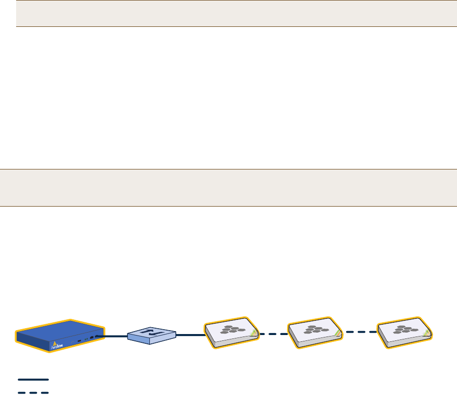
Chapter 7 Using HiveManager
88 Aerohive
•Activate at next reboot: Select to load the software and not activate it. The loaded software gets
activated the next time the HiveAP reboots.
• Select the check box for each HiveAP whose software you want to update.
Updating HiveAPs in a Mesh Environment
When updating hive members in a mesh environment, be careful of the order in which the HiveAPs reboot. If a
portal completes the upload and reboots before a mesh point beyond it completes its upload—which most likely
would happen because portals receive the uploaded content first and then forward it to mesh points—the reboot
will interrupt the data transfer to the mesh point. This can also happen if a mesh point linking HiveManager to
another mesh point reboots before the more distant mesh point completes its upload. As a result of such an
interruption, the affected mesh point receives an incomplete firmware or configuration file and aborts the update.
Figure 9 HiveAPs in a Mesh Environment
To avoid the reboot of an intervening HiveAP from interfering with an ongoing upload to a mesh point beyond it,
allow enough time for the firmware to reach the farthest mesh points before activating the firmware. After all the
HiveAPs have the firmware, rebooting any HiveAPs between them and HiveManager becomes inconsequential.
Note: When choosing which option to use, consider how HiveManager connects to the HiveAPs it is updating.
See "Updating HiveAPs in a Mesh Environment".
Note: A mesh point is a hive member that uses a wireless backhaul connection to communicate with the rest of
the hive. HiveManager manages mesh points through another hive member that acts as a portal, which
links mesh points to the wired LAN.
= Wired Link
= Wireless Link
HiveManager Switch HiveAP
(Portal) HiveAP
(Mesh Point 1) HiveAP
(Mesh Point 2)
When updating HiveAPs in a mesh environment, the HiveManager communicates with mesh points through
their portal and, if there are any intervening mesh points, through them as well. While updating HiveAPs in
such an environment, it is important to keep the path from the HiveManager to all HiveAPs clear so that the
data transfer along that path is not disrupted. Therefore, when updating a firmware image or configuration
on HiveAPs in a mesh environment, make sure that the portal or a mesh point closer to the portal does not
reboot before the upload to a mesh point farther away completes.
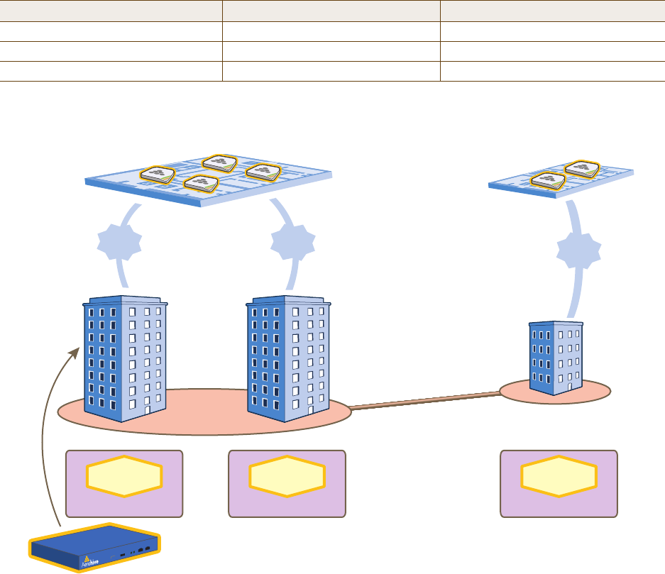
Deployment Guide 89
Chapter 8 HiveManager Configuration Examples
The following examples in this chapter show how to install over 70 HiveAPs at three locations in a corporate
network, use HiveManager to create configurations for them, and then push the configurations to them over the
network. The high-level deployment scheme is as follows:
The general design of the deployment is shown in Figure 1.
Figure 1 Deployment Overview
You can look at any of the following examples individually to study how to configure a specific feature or view all of
them sequentially as a set to study the workflow for deploying large numbers of HiveAPs and configuring them
through HiveManager.
Headquarters - Building 1 (HQ-B1) Headquarters - Building 2 (HQ-B2) Branch Office (Branch1)
32 HiveAPs 32 HiveAPs 8 HiveAPs
1 Hive (hive1) 1 Hive (hive2) 1 Hive (hive3)
1 WLAN policy (WLANpolicy-hq1) 1 WLAN policy (WLANpolicy-hq2) 1 WLAN policy (WLANpolicy-branch1)
x 8
Floors 4 HiveAPs
per Floor x 8
Floors 2 HiveAPs
per Floor x 4
Floors
Corporate
Headquarters Branch
Office
64
HiveAPs
Total
8
HiveAPs
Total
Branch1
HQ-B1 HQ-B2
WLANpolicy-hq1
Hive1
WLANpolicy-hq2
Hive2
WLANpolicy-branch1
Hive3
VPN Tunnel
HiveManager
(in “HQ-B1”)