Aerohive Networks HIVEAP340 802.11 a/b/g/n access point User Manual Aerohive Deployment Guide
Aerohive Networks, Inc. 802.11 a/b/g/n access point Aerohive Deployment Guide
Contents
Users Manual 2
Chapter 1 Preparing for a WLAN Deployment
22 Aerohive
Designing a channel pattern is easier for the 5 GHz spectrum. Depending on the country and the device being used,
there are between 4 and 14 channels available for Wi-Fi use. However, in most countries there are at least 8 to work
with. To simplify the layout of more than 3 channels most use a 7-to-1 pattern, as is shown on the right in Figure 6
on page 21. This channel layout is much more flexible than the 3-channel system and allows for much better
capacity over all channels.
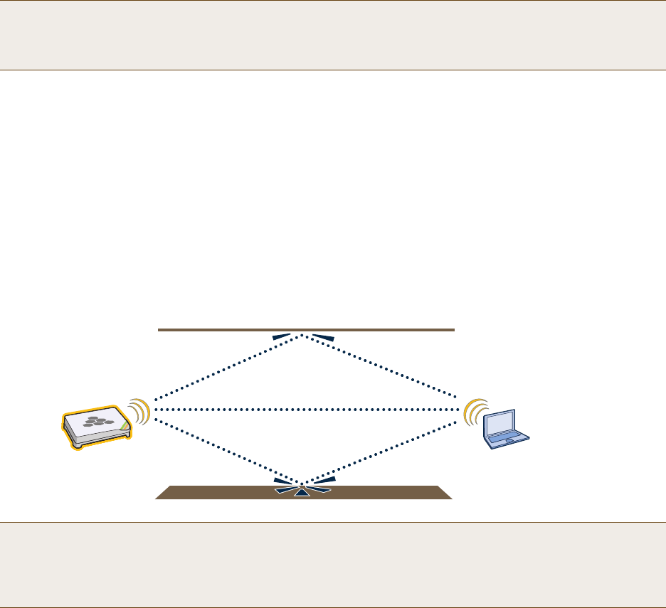
The last topic to cover is the concept of multipaths. When a client receives a transmission from an access point (or
vice versa), the RF signal reaches the client first through a "direct path," but then shortly thereafter by the "indirect
paths" reflected off other objects. The direct path combined with the indirect paths make up multipaths
(see Figure 7). RF signals can bounce off of almost anything—walls, people, plants, and so on—but they bounce the
greatest off of metal. As the RF signals bounce about while propagating, one or more of the secondary paths can
interfere with the primary path, causing the signal strength of the direct path to diminish. In doing so, multipath
can greatly decrease signal to noise ratio.
Figure 7 Multipath Radio Waves
Note: There are alternative 2.4 GHz channel layouts, such as one for four channels using 1, 4, 8 and 11 and
another using channels 1, 5, 9 to counter interference from microwaves, which tend to cause interference
in the high end of the spectrum. Aerohive recommends alternative channel layouts only for the most
challenging radio environments.
Note: If you would like to learn more about how radio frequency propagation works or the details of 802.11,
Wikipedia provides excellent background information under the entries "IEEE 802.11", "radio propagation",
and "multipath". Additionally, spending a few hours with a site survey tool such as AirMagnet Surveyor and
a few test APs can increase both your familiarity with Wi-Fi propagation and your confidence about how it
behaves.
Primary Path
Secondary Path
Secondary Path
Deployment Guide 23
Chapter 2 The HiveAP 20 ag Platform
The Aerohive HiveAP 20 ag is a new generation wireless access point. HiveAPs have the unique ability to
self-organize and coordinate with each other, creating a distributed-control WLAN solution that offers greater
mobility, security, quality of service, and radio control.
This guide combines product information, installation instructions, and configuration examples for both the HiveAP
and HiveManager platforms. This chapter covers the following topics relating to the HiveAP:
•"HiveAP 20 Product Overview" on page 24
•"Ethernet and Console Ports" on page 26
•"Status LEDs" on page 27
•"Antennas" on page 28
•"Mounting the HiveAP 20" on page 29
•"Device, Power, and Environmental Specifications" on page 31
Chapter 2 The HiveAP 20 ag Platform
24 Aerohive
HIVEAP 20 PRODUCT OVERVIEW
The HiveAP 20 ag is a multi-channel wireless AP (access point). It is compatible with IEEE 802.11b/g (2.4 GHz) and
IEEE 802.11a (5 GHz) standards and supports a variety of Wi-Fi (wireless fidelity) security protocols, including WPA
(Wi-Fi Protected Access) and WPA2.
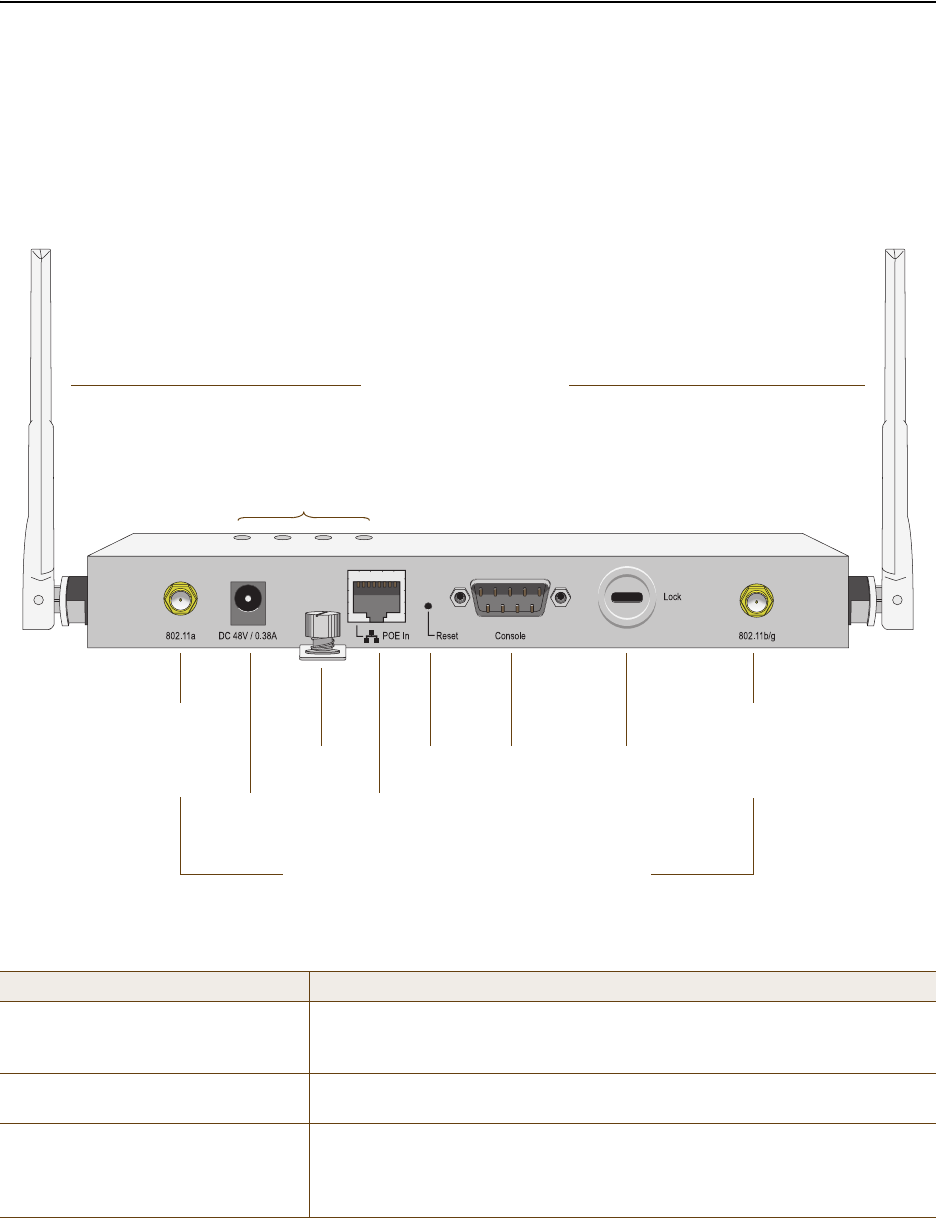
You can see the hardware components on the HiveAP in Figure 1. Each component is described in Table 1.
Figure 1 HiveAP 20 Hardware Components
Table 1 HiveAP 20 Component Descriptions
Component Description
Fixed Dual-Band Antennas The two fixed omnidirectional dipole antennas can operate at two radio
frequencies: 2.4 GHz (for IEEE 802.11b/g) and 5 GHz (for IEEE 802.11a). For
details, see "Antennas" on page 28.
Status LEDs The status LEDs convey operational states for system power, and the LAN,
Access, and Mesh interfaces. For details, see "Status LEDs" on page 27.
802.11a RP-SMA Connector You can connect a detachable single-band antenna, such as the Pulse W1028
dipole antenna for the 5 GHz band, to the male 802.11a RP-SMA (reverse
polarity-subminiature version A) connector. Note that doing so disables the
adjacent fixed antenna.
Power
Connector
Mounting
Screw
10/100 Mbps
Power-over-
Ethernet Port
Reset
Button Console
Port
Device
Lock Slot
Fixed Dual-Band Antennas
Connectors for Detachable Single-Band Antennas
Status LEDs
RP-SMA
Connector for
802.11a
Radio Antenna
RP-SMA
Connector for
802.11b/g
Radio Antenna
Deployment Guide 25
HIVEAP 20 PRODUCT OVERVIEW
Power Connector The 48-volt DC power connector (0.38 amps) is one of two methods through
which you can power the HiveAP 20. To connect it to a 100 – 240-volt AC
power source, use the AC/DC power adaptor that is available as an extra
option. Because the HiveAP does not have an on/off switch, connecting it to
a power source automatically powers on the device.
Mounting Screw To mount the HiveAP 20 on a surface, attach the mounting plate that ships
with the product to the HiveAP by inserting the two pins on the underside of
the chassis into slots in the plate and tightening the mounting screw. For
details, see "Mounting the HiveAP 20" on page 29.
10/100 Mbps PoE Port The 10/100-Mbps Ethernet port supports IEEE 802.3af PoE (Power over
Ethernet) and receives RJ-45 connectors. The HiveAP can receive its power
through an Ethernet connection to power sourcing equipment (PSE) that is
802.3af-compatible. (If you connect the HiveAP to a power source through
the power connector and PoE port simultaneously, the device draws power
through the power connector and automatically disables PoE.)
The HiveAP can also connect to the wired network or to a wired device
(such as a security camera) through this port. It is compatible with
10/100Base-T/TX and automatically negotiates half- and full-duplex
connections with the connecting device. It is autosensing and adjusts to
straight-through and cross-over Ethernet cables automatically. It also
automatically adjusts for 802.3af Alternative A and B methods of PoE. For
details, see "Ethernet and Console Ports" on page 26.
Reset Button The reset button allows you to reboot the device or reset the HiveAP to its
factory default settings. Insert a paper clip, or something similar, into the
Reset pinhole and press the reset button. To reboot the device, hold the
button down between 1 and 5 seconds. To return the configuration to the
factory default settings, hold it down for at least 5 seconds. After releasing
the button, the Power LED goes dark, and then glows steady amber while
the firmware loads and the system performs a self-test. After the software
finishes loading, the Power LED glows steady green.
To disable the reset button from resetting the configuration, enter this
command: no reset-button reset-config-enable Pressing the
button between 1 and 5 seconds will still reboot the HiveAP, but pressing it
for more than 5 seconds will not reset its configuration.
Console Port A male DB-9 serial port to which you can make a console connection using
an RS-232 (or "null modem") cable. The management station from which you
make a serial connection to the HiveAP must have a VT100 emulation
program, such as Tera Term Pro© (a free terminal emulator) or Hilgraeve
Hyperterminal® (provided with Windows® operating systems). The following
are the serial connection settings: bits per second: 9600, data bits: 8,
parity: none, stop bits: 1, flow control: none.
Device Lock Slot You can physically secure the HiveAP by attaching a lock and cable (such as
a Kensington® notebook lock) to the device lock slot. After looping the cable
around a secure object, insert the T-bar component of the lock into the slot
on the HiveAP and turn the key to engage the lock mechanism.
802.11b/g RP-SMA Connector You can connect a detachable single-band antenna, such as the Pulse W1038
dipole antenna for the 2.4 GHz band, to the male 802.11b/g RP-SMA
connector. Note that doing so disables the adjacent fixed antenna.
Component Description
Chapter 2 The HiveAP 20 ag Platform
26 Aerohive
Ethernet and Console Ports
There are two ports on the HiveAP 20: a 10/100Base-T/TX Ethernet port and a male DB-9 console port. Both ports
use standard pin assignments.
The pin assignments in the PoE (Power over Ethernet) Ethernet port follow the TIA/EIA-568-B standard (see
Figure 2). The PoE port accepts standard types of Ethernet cable—cat3, cat5, cat5e, or cat6—and can receive power
over this cable from power sourcing equipment (PSE) that is 802.3af-compatible. Such equipment can be embedded
in a switch or router, or it can come from purpose-built devices that inject power into the Ethernet line en route to
the HiveAP. Because the PoE port has autosensing capabilities, the wiring termination in the Ethernet cable can be
either straight-through or cross-over.
Figure 2 PoE Wire Usage and Pin Assignments
Pin T568A Wire Color
1 White/Green
2 Green
3 White/Orange
4Blue
5 White/Blue
6 Orange
7 White/Brown
8Brown
(View of the PoE port
on the HiveAP)
1 8
Pin Numbers
Pin T568B Wire Color
1 White/Orange
2 Orange
3 White/Green
4Blue
5 White/Blue
6 Green
7 White/Brown
8Brown
T568A-Terminated Ethernet Cable
with an RJ-45 Connector
802.3af Alternative A
(Data and Power on
the Same Wires)
802.3af Alternative B
(Data and Power on
Separate Wires)
Pin Data Signal MDI MDI-X MDI or MDI-X
1 Transmit + DC+ DC– – – –
2 Transmit - DC+ DC– – – –
3 Receive + DC– DC+ – – –
4 (unused) – – – – – – DC+
5 (unused) – – – – – – DC+
6 Receive - DC– DC+ – – –
7 (unused) – – – – – – DC–
8 (unused) – – – – – – DC–
MDI = Medium dependent interface for straight-through connections
MDI-X = Medium dependent interface for cross-over (X) connections
The PoE port is auto-sensing and can automatically adjust to transmit and receive data over straight-through or cross-over Ethernet
connections. Likewise, it can automatically adjust to 802.3af Alternative A and B power delivery methods. Furthermore, when the
Alternative A method is used, the PoE port automatically allows for polarity reversals depending on its role as either MDI or MDI-X.
T568B -terminated Ethernet Cable
with an RJ-45 Connector
T568A and T568B are two standard
wiring termination schemes. Note that
the only difference between them is
that the white/green + solid green pair
of wires and the white/orange + solid
orange pair are reversed.
For straight-through Ethernet
cables—using either the T568A or
T568B standard—the eight wires
terminate at the same pins on each
end.
For cross-over Ethernet cables, the
wires terminate at one end according
to the T568A standard and at the
other according to T568B.
Deployment Guide 27
HIVEAP 20 PRODUCT OVERVIEW
The pin assignments in the male DB-9 console port follow the EIA (Electronic Industries Alliance) RS-232 standard. To
make a serial connection between your management system and the console port on the HiveAP, you can use a null
modem serial cable, use another serial cable that complies with the RS-232 standard, or refer to the pin-to-signal
mapping shown in Figure 3 to make your own serial cable. Connect one end of the cable to the console port on the
HiveAP and the other end to the serial (or COM) port on your management system. The management system must
have a VT100 terminal emulation program, such as Tera Term Pro© (a free terminal emulator) or Hilgraeve
Hyperterminal® (provided with Windows® operating systems).
Figure 3 Console Port Pin Assignments
Status LEDs
The four status LEDs on the top of the HiveAP 20 indicate various states of activity through their color (dark, green,
amber) and illumination patterns (steady glow or blinking). The meanings of the various color + illumination
patterns for each LED are explained below.
Power
•Dark: No power
• Steady green: Powered on and the firmware is running normally
• Steady amber: Firmware is booting up or is being updated
• Blinking amber: Alarm indicating firmware failure
LAN• Dark: Ethernet link is down or disabled
• Steady green: Ethernet link is up but inactive
• Blinking green: Ethernet link is up and active
Access
• Dark: Wireless link is disabled
• Steady green: Wireless link is up but inactive
• Blinking green: Wireless link is up and active
Mesh
• Dark: Wireless link is disabled
• Steady green: Wireless link is up but inactive
• Blinking green (fast): Wireless link is up and the HiveAP is searching for other hive members
• Blinking green (slowly): Wireless link is up and active
12 3 45
6 7 8 9
Pin Signal Direction
1 DCD (Data Carrier Detect) (unused)
2 RXD (Received Data) Input
3 TXD (Transmitted Data) Output
4 DTR (Data Terminal Ready) (unused)
5 Ground Ground
6 DSR (Data Set Ready) (unused)
7 RTS (Request to Send) (unused)
8 CTS (Clear to Send) (unused)
9 RI (Ring Indicator) (unused)
Male DB-9 Console Port
(View of the console
port on the HiveAP) The above pin assignments show a DTE (data terminal equipment)
configuration for a DB-9 connector complying with the RS-232 standard.
Because this is a console port, only pins 2, 3, and 5 need be used.
RS-232 Standard Pin Assignments
Chapter 2 The HiveAP 20 ag Platform
28 Aerohive
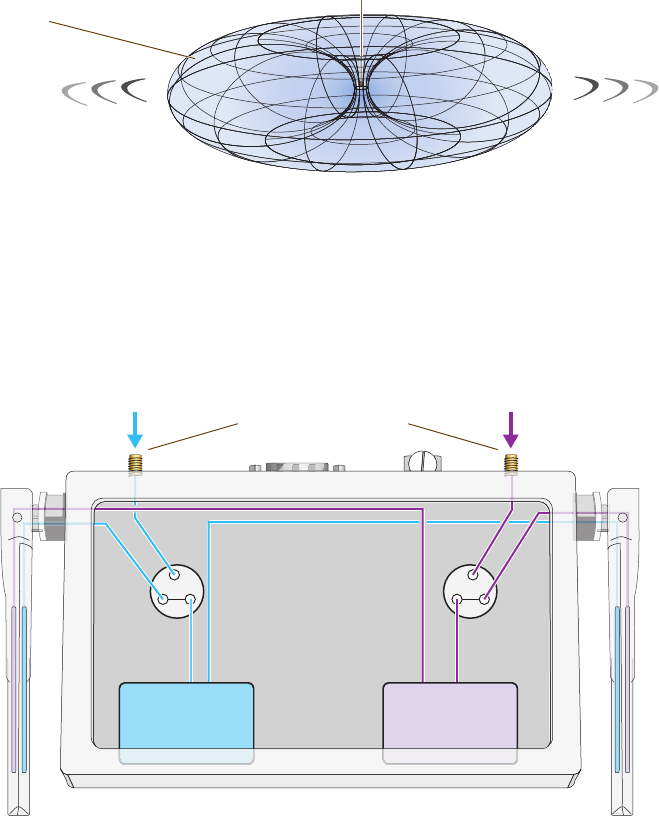
Antennas
The HiveAP 20 includes two fixed dual-band antennas with 3-dBi gains. These antennas are omnidirectional,
providing fairly equal coverage in all directions in a toroidal (donut-shaped) pattern around each antenna. When the
antennas are vertically positioned, coverage expands primarily on the horizontal plane, extending horizontally much
more than vertically. See Figure 4, which shows the toroidal pattern emanating from a single vertically positioned
antenna. To change coverage to be more vertical than horizontal, position the antennas horizontally. You can also
resize the area of coverage by increasing or decreasing the signal strength.
Figure 4 Omnidirectional Radiation Pattern
The pair of fixed dual-band antennas operate concurrently in two different frequency ranges: 2.4 GHz (IEEE
802.11b/g) and 5 GHz (IEEE 802.11a). Using two different frequency ranges reduces the probability of interference
that can occur when numerous channels operate within the same range. Conceptually, the relationship of antennas
and radios is shown in Figure 5.
Figure 5 Antennas and Radios
\
After connecting an external antenna to an RP-SMA connector, you must enter the following command to move the
appropriate interface from the adjacent fixed antenna to the external antenna:
interface interface radio antenna external
Note: To show the shape of radiation more clearly,
this illustration depicts the coverage provided by
only one active antenna and is not drawn to scale.
The omnidirectional antennas
radiate equally in all directions,
forming a toroidal pattern.
HiveAP
Radio 1
RF 802.11b/g
2.4 GHz
Radio 2
RF 802.11a
5 GHz
Antenna
Switch 1 Antenna
Switch 2
RP-SMA Connectors
802.11a/b/g
Dual-Band
Fixed
Antenna
802.11a/b/g
Dual-Band
Fixed
Antenna
Cut-away view of the HiveAP to show the relationship
of the antennas and the two internal radios.
Deployment Guide 29
MOUNTING THE HIVEAP 20
The wifi0 interface links to radio 1 (frequency range = 2.4 GHz for IEEE 802.11b/g), and the wifi1 interface links to
radio 2 (frequency range = 5 GHz for IEEE 802.11a). These interface-to-radio relationships are permanent. However,
the interface-to-antenna relationships can be shifted. In other words, you can change which antenna—fixed or
external—the wifi0 and wifi1 interfaces use. For example, to link the wifi0 interface to an external antenna
connected to the 802.11b/g RP-SMA connector (for radio 1), enter the following command:
interface wifi0 radio antenna external
If you do not enter this command, the wifi0 interface and all its subinterfaces (wifi0.1, wifi0.2, wifi0.3, and wifi0.4)
continue to use both fixed antennas.
To unlink the wifi0 interface from the external antenna and return it to the fixed antennas, enter this command:
interface wifi0 radio antenna internal
MOUNTING THE HIVEAP 20
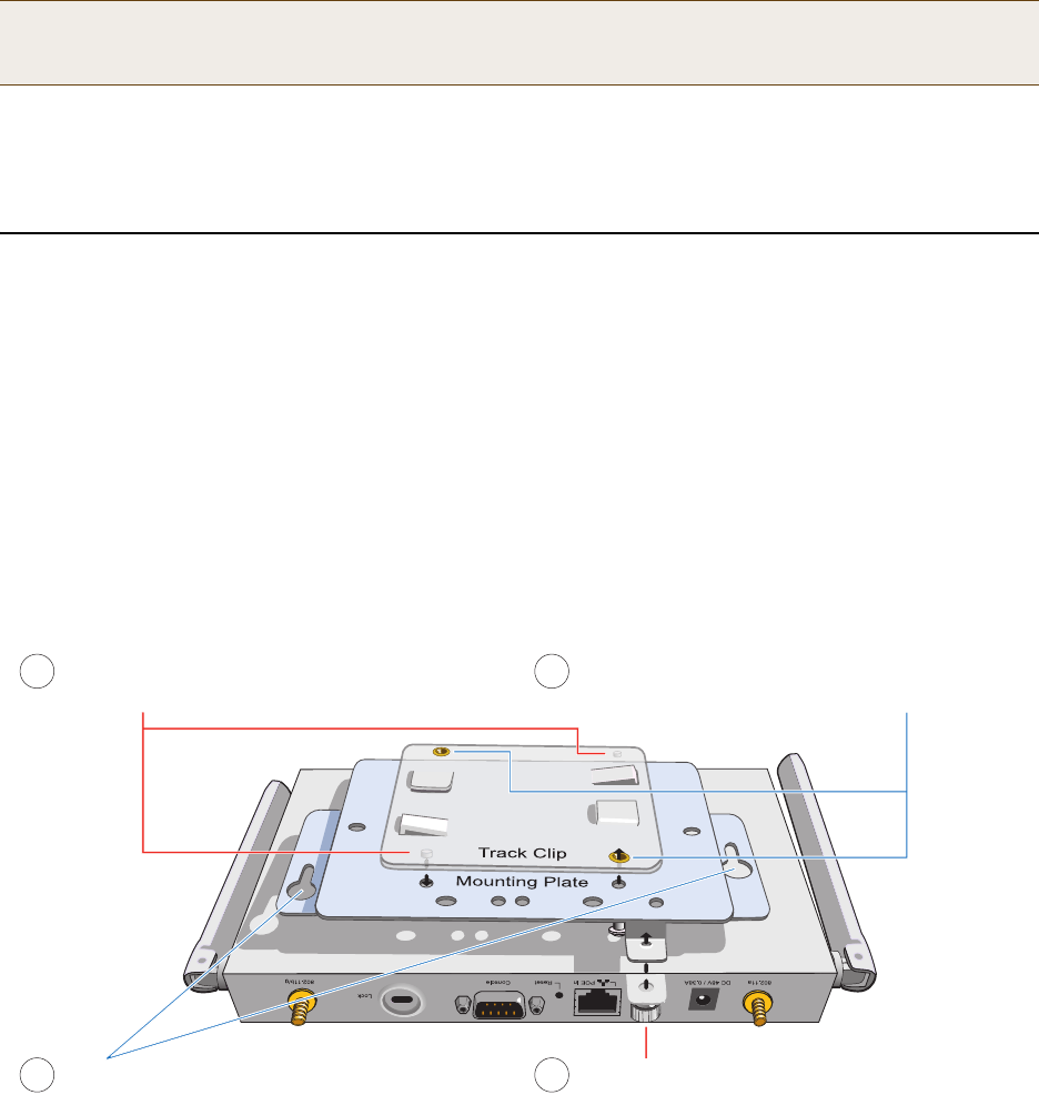
Using the mounting plate and track clip, you can mount the HiveAP 20 to the tracks of a dropped ceiling grid. Using
just the mounting plate, you can mount the HiveAP to any surface that can support its weight (1.5 lb., 0.68 kg).
Ceiling Mount
To mount the HiveAP 20 to a track in a dropped ceiling, you need the mounting plate, track clip, and two cross-head
screws that ship with the track clip. You also need a cross-head screw driver and—most likely—a ladder.
Attach the track clip to the mounting plate, and then attach the clip-plate combination to the HiveAP 20, as shown
in Figure 6.
Figure 6 Attaching the HiveAP 20 to the Mounting Plate and Track Clip
Note: After entering the above command, the radio to which you attached the external antenna uses the
external antenna and the fixed antenna on the opposite side of the HiveAP. Attaching an external antenna
only disconnects the adjacent fixed antenna. Note the two antenna switches shown in Figure 5 on page 28.
Align the two projecting posts on the underside of
the track clip with holes in the mounting plate. Using the two cross-head screws that ship with the
track clip, fasten the mounting plate to the track clip.
Insert the pins on the underside of the HiveAP
into the two slots in the mounting plate. Use the mounting screw to secure the HiveAP
to the plate.
12
34
Chapter 2 The HiveAP 20 ag Platform
30 Aerohive
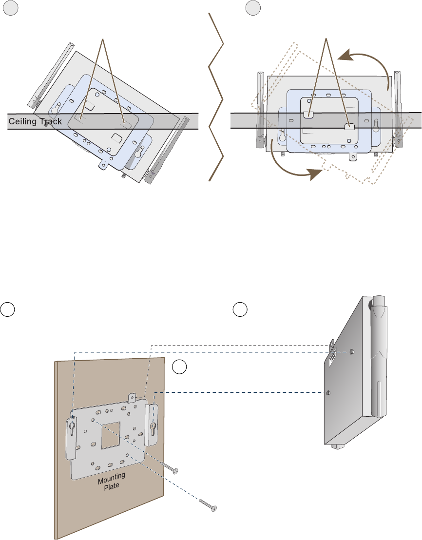
Nudge the ceiling tiles slightly away from the track to clear some space. Then attach the track clip to the ceiling
track as shown in Figure 7. When done, adjust the ceiling tiles back into their former position.
Figure 7 Attaching the HiveAP to a Dropped Ceiling Track
Surface Mount
You can use the mounting plate to attach the HiveAP 20 to any surface that supports its weight, and to which you
can screw or nail the plate. First, mount the plate to the surface, and then attach the device to the plate, as shown
in Figure 8.
Figure 8 Mounting the HiveAP on a Wall
Press the track clip against the ceiling track so
that the the track contacts the two pressure tabs
and pushes them flush with the track clip.
Rotate the HiveAP and the mounting
accessories attached to it until the two
clipping tabs grip the ceiling track.
56
(bird’s eye view
with ceiling tiles
removed for clarity)
Use the mounting screw
to secure the HiveAP 20
to the plate.
Insert the pins on the underside of
the HiveAP 20 into the two slots.
With the two wings at the sides of the plate extending
away from the surface, attach the mounting plate to a
secure object such as a wall, ceiling, post, or beam.
1
2
3
Note: There are a variety of holes through which you can
screw or nail the plate in place. Choose the two or three
that best suit the object to which you are attaching it.

Deployment Guide 31
DEVICE, POWER, AND ENVIRONMENTAL SPECIFICATIONS
DEVICE, POWER, AND ENVIRONMENTAL SPECIFICATIONS
Understanding the range of specifications for the HiveAP 20 is necessary for optimal deployment and device
operation. The following specifications describe the physical features and hardware components, the power adapter
and PoE (Power over Ethernet) electrical requirements, and the temperature and humidity ranges in which the
device can operate.
Device Specifications
• Chassis dimensions: 8 1/4" W x 1" H x 4 15/16" D (21 cm W x 2.5 cm H x 12.5 cm D)
• Weight: 1.5 lb. (0.68 kg)
• Antennas: Two fixed dual-band 802.11a/b/g antennas, and two RP-SMA connectors for detachable single-band
802.11a or 802.11b/g antennas
• Serial port: DB-9 (bits per second: 9600, data bits: 8, parity: none, stop bits: 1, flow control: none)
• Ethernet port: autosensing 10/100Base-T/TX Mbps, with IEEE 802.3af-compliant PoE (Power over Ethernet)
Power Specifications
• AC/DC power adapter:
• Input:100 – 240 VAC
• Output: 48V/0.38A
• PoE nominal input voltages: 48 V, 0.35A
• RJ-45 power input pins: Wires 4, 5, 7, 8 or 1, 2, 3, 6
Environmental Specifications
• Operating temperature: 32 to 122 degrees F (0 to 50 degrees C)
• Storage temperature: -4 to 158 degrees F (-20 to 70 degrees C)
• Relative Humidity: Maximum 95%
Chapter 2 The HiveAP 20 ag Platform
32 Aerohive

Deployment Guide 33
Chapter 3 The HiveAP 28 Outdoor Platform
The Aerohive HiveAP 28 is a new generation wireless access point that is customized for outdoor use. It is mountable
in any direction and on any hard surface, post, or wire strand. It can receive power either through an Ethernet cable
or power cord.
This guide combines product information, installation instructions, and configuration examples for both the HiveAP
and HiveManager platforms. This chapter covers the following topics relating to the HiveAP 28:
•"HiveAP 28 Product Overview" on page 34
•"Ethernet Port" on page 35
•"Power Connector" on page 36
•"Antennas" on page 37
•"Mounting the HiveAP 28 and Attaching Antennas" on page 38
•"Pole Mount" on page 39
•"Strand Mount" on page 40
•"Surface Mount" on page 41
•"Attaching Antennas" on page 42
•"Device, Power, and Environmental Specifications" on page 44
Note: Do not open the HiveAP 28 chassis. There are no serviceable parts inside.
Chapter 3 The HiveAP 28 Outdoor Platform
34 Aerohive
HIVEAP 28 PRODUCT OVERVIEW
The HiveAP 28 is a multi-channel wireless AP (access point) for outdoor use. It is compatible with IEEE 802.11b/g
(2.4 GHz) and IEEE 802.11a (5 GHz) standards and supports a variety of Wi-Fi (wireless fidelity) security protocols,
including WPA (Wi-Fi Protected Access) and WPA2.
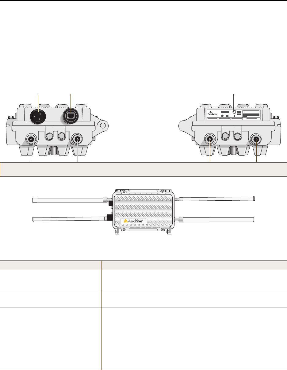
You can see the hardware components on the HiveAP 28 in Figure 1. Each component is described in Table 1.
Figure 1 HiveAP 28 Hardware Components
Table 1 HiveAP 28 Component Descriptions
Component Description
Detachable Single-Band Antennas The two pairs of detachable omnidirectional dipole antennas operate at
two radio frequencies: one pair at 2.4 GHz (for IEEE 802.11b/g) and the
other at 5 GHz (for IEEE 802.11a). For details, see "Antennas" on page 37.
Type N Connectors (Female) Attach antennas to the HiveAP 28 through these connectors. For details,
see "Attaching Antennas" on page 42.
Waterproof Power Connector Using the power connector is one of two methods through which you can
power the HiveAP 28. To connect it to a 100 – 240-volt AC power source,
use the power cable that ships with the product as an extra option.
Because the HiveAP does not have an on/off switch, connecting it to a
power source automatically powers on the device. The power source
must have a readily accessible service disconnect switch incorporated
into the fixed wiring installation so that you have the ability to turn the
power on and off. (The other method that the HiveAP can obtain power is
through its PoE port.)
5 GHz 2.4 GHz 5 GHz 2.4 GHz
Power
Connector
10/100 Mbps
Power-over-
Ethernet Port
Type N female connectors for
detachable single-band antennas
For the 802.11a
Radio Antenna For the 802.11b/g
Radio Antenna For the 802.11a
Radio Antenna For the 802.11b/g
Radio Antenna
FCC Compliance Label
(Plus model, serial number, MAC
address, and FCC ID number)
802.11a Main Antenna (5 GHz) 802.11b/g Main Antenna (2.4 GHz)
802.11b/g Auxiliary Antenna (2.4 GHz) 802.11a Auxiliary Antenna (5 GHz)
Deployment Guide 35
HIVEAP 28 PRODUCT OVERVIEW
Ethernet Port
The HiveAP 28 has a 10/100Base-T/TX PoE (Power over Ethernet) port. Its pin assignments follow the TIA/EIA-568-B
standard (see Figure 2 on page 26). The PoE port accepts standard types of Ethernet cable—cat3, cat5, cat5e, or
cat6—and can receive power over this cable from power sourcing equipment (PSE) that is 802.3af-compatible. Such
equipment can be embedded in a switch or router, or it can come from purpose-built devices that inject power into
the Ethernet line en route to the HiveAP. Because the PoE port has autosensing capabilities, the wiring termination
in the Ethernet cable can be either straight-through or cross-over (MDI/MDI-X). For outdoor deployments use
weatherproofed shielded twisted pair (STP) Ethernet cables.
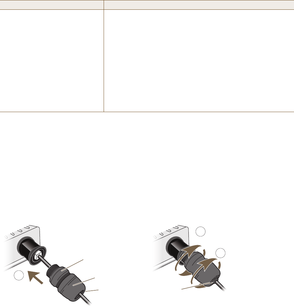
To ensure a waterproof seal for the Ethernet connection, use the RJ-45 connector assembly, which comes in three
parts: a compression nut, end cap, and gasket.
Figure 2 Connecting the Ethernet Cable
1. Insert one end of the Ethernet cable through the waterproof RJ-45 connector assembly and plug the cable into
the Ethernet port.
2. Tighten the compression nut by twisting it clockwise into the Ethernet port housing on the chassis.
3. Tighten the end cap by twisting it clockwise onto the compression nut and tighten until the rubber gasket
emerges and wrap itself around the Ethernet cable.
The Ethernet connection is now sealed and waterproof.
10/100 Mbps PoE Port The 10/100-Mbps Ethernet port supports IEEE 802.3af PoE (Power over
Ethernet) and receives RJ-45 connectors. The HiveAP can receive its
power through an Ethernet connection to PSE (power sourcing
equipment) that is 802.3af-compatible. (If you connect the HiveAP to a
power source through the power connector and PoE port simultaneously,
the device draws power through the power connector and automatically
disables PoE.)
The HiveAP 28 can also connect to the wired network or to a wired device
(such as a security camera) through this port. It is compatible with
10/100Base-T/TX and automatically negotiates half- and full-duplex
connections with the connecting device. It is autosensing and adjusts to
straight-through and cross-over Ethernet cables automatically
(MDI/MDI-X). It also automatically adjusts for 802.3af Alternative A and B
methods of PoE. For details, see "Ethernet Port".
Component Description
2
Compression Nut
End Cap
Gasket
(inside) Gasket
(squeezed out)
1
3
Slide the Ethernet cable through the two
halves of the waterproof RJ-45 connector
assembly, screw the halves loosely together,
and then plug the cable into the Ethernet port.
Tighten the compression nut
into the Ethernet port housing
on the chassis.
Tighten the end cap until
the gasket is squeezed out
the opening and forms a
watertight seal around the
cable.

Chapter 3 The HiveAP 28 Outdoor Platform
36 Aerohive
4. Connect the other end of the Ethernet cable to PSE (power sourcing equipment), such as a power injector, if the
HiveAP 28 receives power through PoE, or directly to a network device, such as a switch, if it receives power
through a power cord.
If the Ethernet cable connects the HiveAP to another device that is indoors, you must install appropriate
lightning protection at the point before it enters the building. Failing to do so might cause damage to the
equipment as well as serious injury or death.
Power Connector
The HiveAP 28 can receive power through an Ethernet cable using PoE or through a power cord. Aerohive
recommends using either PoE or wiring the power cord directly to a 100 – 240-volt AC power source. Only plug the
power cord into an electric outlet when configuring the device before deployment or when testing it in the lab.
To connect the power cord to the HiveAP 28:
1. Align the slot in the power cord plug with the small tab at the top of the three-pin power connector, and slide
the plug firmly over the pins until it is fully seated in the power connector.
2. Slide the cover over the connector and tighten it by turning the cover clockwise.
3. Install a lightning protector between the HiveAP 28 and its power source.
4. When possible, run the cord through a conduit to protect it from the elements. Where the cord is exposed,
allow enough slack in it to create a drip loop. Leaving some slack in the cord lets water run away from the
connections at each end. Use only a weatherproof power cord, such as the cord that ships with the HiveAP 28.
5. Strip the other end of the power cord and wire it directly to a power source, such as a junction box that has a
service disconnect switch that you can use to turn the power on and off. Also, because the HiveAP 28 does not
have short-circuit (over current) protection built into it, it relies on the protection provided by the power
source to which you connect it. Ensure that the protective device, such as a circuit breaker, is not rated greater
than 15A. Furthermore, if you need to install the HiveAP 28 in a wet or damp location, the AC branch circuit
that is powering it must be provided with ground fault protection (GFCI), as required by Article 210 of the
National Electrical Code (NEC).
Note: To prevent damage to the HiveAP 28 or power injector when using PoE to provide power, connect the
Ethernet cable from the power injector to the HiveAP 28, and connect the injector to a power jack
before applying power.
Note: When the HiveAP acts as a mesh point and does not use the Ethernet port, cover the Ethernet port with a
connector cap to prevent water intrusion and possible safety hazards.
Note: When the HiveAP receives power through PoE, cover the power connector with a connector cap to prevent
water intrusion and possible safety hazards.
Note: The HiveAP 28 must be grounded. Do not operate it unless there is a suitably installed ground
conductor. Contact the appropriate electrical inspection authority or an electrician if you are
uncertain that suitable grounding is available.
Deployment Guide 37
HIVEAP 28 PRODUCT OVERVIEW
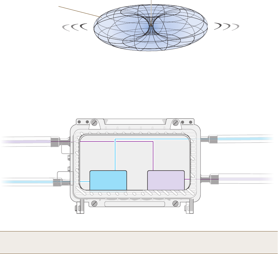
Antennas
The HiveAP 28 includes two detachable single-band antennas with 8dBi gains (802.11b/g) and two detachable
single-band antennas with 10dBi gains (802.11a). These antennas are omnidirectional, providing fairly equal
coverage in all directions in a toroidal (donut-shaped) pattern around each antenna. When the antennas are
vertically positioned, coverage expands primarily on the horizontal plane, extending horizontally much more than
vertically. See Figure 3, which shows the toroidal pattern emanating from a single vertically positioned antenna.
Note that when high gain antennas are added, the torus shape becomes somewhat elongated or compressed. If the
HiveAP 28 is mounted higher than 20 feet the center of the torus curves inward so that the connection quality,
directly underneath the center of the HiveAP 28, becomes compromised.
To change coverage to be more vertical than horizontal, position the HiveAP so that the antennas are on a
horizontal plane. You can also resize the area of coverage by increasing or decreasing the signal strength.
Figure 3 Omnidirectional Radiation Pattern
The pairs of antennas operate concurrently in two different frequency ranges: 2.4 GHz (IEEE 802.11b/g) and 5 GHz
(IEEE 802.11a). Using two different frequency ranges reduces the probability of interference that can occur when
numerous channels operate within the same range. Conceptually, the relationship of antennas and radios is shown in
Figure 4. (For information about attaching the antennas to the HiveAP 28, see "Attaching Antennas" on page 42.)
Figure 4 Antennas and Radios
\
Note: The HiveAP 20 uses interface interface radio antenna external command to enable an
external antenna attached to it. Entering this command on the HiveAP 28 disables the antenna on the
opposite side of the device from the radio to which the interface is linked and results in a loss of diversity.
Note: To show the shape of radiation more clearly,
this illustration depicts the coverage provided by
only one active antenna and is not drawn to scale.
The omnidirectional antennas
radiate equally in all directions,
forming a toroidal pattern.
HiveAP
The two 802.11b/g antennas link internally to Radio 1
and broadcast in the 2.4 GHz frequency range.
802.11a Main Antenna 802.11b/g Main Antenna
802.11b/g Auxiliary Antenna 802.11a Auxiliary Antenna
The two 802.11a antennas link internally to Radio 2
and broadcast in the 5 GHz frequency range.
Radio 1
RF 802.11b/g
2.4 GHz
Radio 2
RF 802.11a
5 GHz

Chapter 3 The HiveAP 28 Outdoor Platform
38 Aerohive
MOUNTING THE HIVEAP 28 AND ATTACHING ANTENNAS
Using the mounting accessories (available separately) you can mount the HiveAP in various locations:
•"Pole Mount" on page 39 – Mount the HiveAP 28 on a pole such as a street light.
•"Strand Mount" on page 40 – Suspend the HiveAP 28 from a cable or phone line.
•"Surface Mount" on page 41 – Mount the HiveAP 28 on a flat surface such as a wall or beam.
You can mount the HiveAP 28 in any of these locations as long as the object to which you mount it and the attaching
screws can support its weight (9 lbs., 4.08 kg).
After mounting the HiveAP 28, attach the antennas as explained in "Attaching Antennas" on page 42.
Before you mount the HiveAP 28 and attach antennas, read the following warnings and cautions:
• To install the HiveAP 28, you must be a qualified installation professional, licensed or certified in
accordance with local regulations.
• Use lightning arrestors and ground both the HiveAP 28 and any separately mounted antennas.
• Do not connect or disconnect antennas or cables from the HiveAP 28 during periods of lightning activity.
• If you need to place the HiveAP 28 in an explosive environment, such as in an oil refinery, mine, or any
place where there is flammable gas, it must first be encased in an ATEX enclosure.
• To comply with RF (radio frequency) exposure limits, do not place antennas within 6.56 feet (2 meters) of
people.
• Do not locate antennas near overhead power lines or other electric light or power circuits, or where they
can come into contact with such circuits. When installing antennas, take extreme care not to come into
contact with these circuits, which might cause serious injury or death. For proper installation and grounding
of the antenna, refer to national and local electrical codes: NFPA (National Fire Protection Association) 70,
National Electrical Code Article 810 (U.S.); Canadian Electrical Code, Part I, CSA 22.1 and Section 54
(Canada); and if local or national electrical codes are not available, refer to IEC (International
Electrotechnical Commission) 364, Part 1 through 7 (other countries).
• To prevent damage, avoid over-tightening the connectors, nuts, and screws used to mount the HiveAP 28
and antennas.
Deployment Guide 39
MOUNTING THE HIVEAP 28 AND ATTACHING ANTENNAS
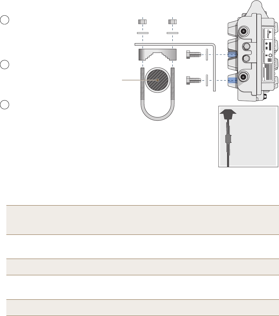
Pole Mount
To mount the HiveAP 28 to a pole with a 1.5-inch diameter, you need two sets of the L-shaped brackets, two 2"
U-bolts, saddle clamps, and the nuts, bolts, and washers shown in Figure 5. You also need a wrench to tighten the
nuts and bolts securely.
Figure 5 Attaching the HiveAP 28 to a Pole
1. Align two of the holes in the shorter end of the bracket with two of the holes in the HiveAP, insert the two bolts
through the washers and bracket, and screw them into the holes in the HiveAP 28 chassis, using a wrench to
tighten the bolts so that the bracket is securely attached.
2. Holding a saddle clamp against the inside of the long end of one of the L-shaped brackets, slip a U-bolt around
the pole and thread it through the two holes in the saddle clamp and L-shaped bracket.
3. Thread a split washer and 5/16-18 nut to each end of the U-bolt, and tighten them with a wrench to secure the
U-bolt firmly to the pole.
Note: Repeat this step to attach the other bracket to the HiveAP. However, this time, place the long end of
the bracket in the opposite direction of the first one for better stability. For example, if you attached
the first bracket with its long end positioned toward the outside edge of the device, install this second
bracket with the long end of the bracket toward the middle.
Note: One of the holes in the bracket is arc-shaped so that you can adjust the angle of the mounted device if
necessary.
Note: Repeat steps 2 and 3 to attach the other U-bolt and saddle clamp to the remaining L-shaped bracket
and secure the HiveAP 28 to the pole.
5 GHz 2.4 GHz
Saddle Clamp
Vertical Pole
(1.5” diameter)
2” U-Bolt
Split Washers
5/16-18 Nuts
L-Shaped Bracket
1/4-20 Bolts
and
Split Washers
Bird’s-Eye View
Side view of the
HiveAP 28
mounted to a
street light
Note: For clarity, only one post mounting
set is shown in the illustration. You also
need to use a second set to finish mounting
the HiveAP on a pole.
Use the 1/4-20 bolts and split
washers to attach the shorter end of
the L-shaped bracket to holes in the
underside of the HiveAP 28.
Slip the U-bolt around the pole and
thread its ends through the saddle
clamp and L-shaped bracket.
Thread the split washers and
5/16-18 nuts over the ends of the
U-bolt and tighten until the bracket
assembly and device are secured to
the pole.
1
2
3
Chapter 3 The HiveAP 28 Outdoor Platform
40 Aerohive
Strand Mount
The HiveAP 28 outdoor platform can also be mounted on a cable or strand of wire as shown in Figure 6. When
mounted on a wire strand, use 90-degree N type adapters (not included) to orient the antennas vertically. If you do
not use the adapters and orient the antennas horizontally, the area covered will be far less.
Figure 6 Clamping the HiveAP 28 to a Wire Strand
To mount the HiveAP 28 on a wire or strand, you need a wrench and two 1/4-20 bolts, split washers, strand clamps,
and 90-degree type N adapters. In the following instructions, you use only the 2.4 GHz antennas.
1. Position the HiveAP 28 so that its long side (with three holes at each end) is underneath a cable or wire strand
running lengthwise along the upper side of the chassis (for the proper orientation, see the inset in Figure 6).
2. Place the strand clamp over the wire and use the 1/4-20 bolt and split washer to secure the strand between the
clamp and chassis.
3. Attach the 90-degree type N adapters to the two 2.4 GHz antenna connectors and then attach the antennas to
the adapters so that the antennas face downward. For details, see "Attaching Antennas" on page 42.
Note: Repeat the preceding steps to fasten the other end of the HiveAP 28 to the cable or wire strand.
5 GHz 2.4 GHz
Strand Clamp
Split Washer
Strand
1/4-20 Bolt
End View
Side View
Side view of the
HiveAP 28 mounted
on a cable strand
90-Degree
Type N Adapter
90-Degree
Type N Adapter
2.4 GHz Antennas
Note: For clarity, only one bolt, washer,
and strand clamp are shown in the
illustration on the left. You also need to use
a second set of these items to finish
clamping the HiveAP to a wire strand.
Position the HiveAP 28 so that
its long side is directly beneath
a cable or wire strand.
Place the strand clamps over the
wire, and bolt the clamps tightly to
the chassis around the strand.
1
2
Attach 90-degree type N adapters to the
2.4 GHz antenna connectors so that the
adapters face downward, and then
attach the antennas to the adapters
3
Deployment Guide 41
MOUNTING THE HIVEAP 28 AND ATTACHING ANTENNAS
Surface Mount
You can use the mounting plate to attach the HiveAP 28 to any surface that supports its weight (9 lbs., 4.08 kg), and
to which you can screw or nail the plate. First, mount the plate to the HiveAP 28, and then attach the plate to the
surface, as shown in Figure 7. Note that the screw heads that you attach to the wall or surface must be small
enough for the keyholes on the mounting plate to slip over them.
Figure 7 Mounting the HiveAP 28 on a Wall
To mount the HiveAP 28 to a surface like a wall, you need two mounting plates, four 1/4-20 x 1/2" flat head screws,
four screws (no bigger than 5/16"), and a screw driver:
1. Align the ridged edge of one of the mounting plates with two of the holes located on the underside of the
HiveAP 28, and use two 1/4-20 x 1/2" flat head screws to secure the plate against the HiveAP 28. Then attach
the other mounting plate to the HiveAP 28 in the same way.
2. Attach four 5/16" screws to a wall or beam. They must be 8 1/8" (206 mm) apart vertically and 7 7/8" (200 mm)
apart horizontally to accommodate the keyholes on the mounting plates.
3. Guide the keyholes over the screws fastened to the wall and push downward after the screw heads have cleared
the keyholes.
Note: Because the metal in a wall can degrade the radio signal pattern, Aerohive recommends using sector
antennas instead of omnidirectional antennas when mounting the device on a wall.
5 GHz 2.4 GHz
7 7/8”
200 mm
Top of Wall
5 GHz 2.4 GHz
Mounting Plate
1/4-20 x 1/2”
Flat Head Screws
Bird’s-Eye View
Side view of the
HiveAP 28 mounted
on an exterior wall
Guide the screws fastened to
the wall through the keyholes
in the mounting plates.
Attach four screws to a secure object
such as a wall or beam. Space them
8 1/8" (206 mm) apart vertically and
7 7/8" (200 mm) apart horizontally.
With the ridged edge of the holes on the
mounting plates facing the HiveAP 28, use
1/4-20 x 1/2 inch screws to secure the two
mounting plates to its underside.
1 2 3
Note: For clarity, only one mounting plate is shown in the illustration.
You also need a second plate with another set of screws.

Chapter 3 The HiveAP 28 Outdoor Platform
42 Aerohive
Attaching Antennas
You can connect the antennas directly to the HiveAP 28 or mount them separately. Although connecting the
antennas directly to the device typically provides better performance, in some cases the location of the HiveAP
might not be a good location for the antennas; for example, if the HiveAP 28 is mounted on a reinforced concrete
wall that interferes with radio coverage. In such cases, mounting the antennas separately in a more open location
can improve coverage; however, bear in mind that cables introduce loss into the overall signal strength and that the
longer the cable connecting the antennas to the HiveAP 28, the greater the loss will be.
Connecting Antennas Directly to the HiveAP 28
The two 2.4 GHz and two 5 GHz antennas that ship with the HiveAP 28 have male Type N connectors that you can
connect directly to the female Type N antenna connectors on the HiveAP 28. You can also use self-amalgamating
PTFE (polytetrafluoroethylene) tape, which is available separately from Aerohive, to create a waterproof seal at the
points of attachment.
To attach the antennas:
1. Remove the antenna connector covers from the HiveAP 28 (leave the covers on any connectors that you do not
plan to use), and make sure that the surface of the connectors on the HiveAP 28 and the connectors on the
antennas are clean.
2. If you are using PTFE tape, wrap the tape around the threads on the HiveAP 28 antenna connectors as follows:
2.1. Starting at one end of the threads on one of the connectors, stretch the tape and wrap it in half-lap
layers until you cover the threads completely.
2.2. Wrap the tape in the opposite direction to bring it back onto itself for one full wrap.
2.3. Place one thumb on the tape at the point of termination and stretch the tape until it breaks.
2.4. Repeat the preceding steps to cover all the connectors to which you will attach antennas.
3. Connect the 2.4 GHz antennas to the 2.4 GHz antenna connectors. (To tighten an antenna, turn the antenna
base cap—the textured metal band that encloses the connector—clockwise over the tape-covered threads of the
HiveAP antenna connector.)
Their connections are now sealed and waterproof.
4. Repeat the preceding steps to connect the 5 GHz antennas.
Mounting Antennas Separately
In addition to connecting antennas directly to the HiveAP 28, you can also mount them separately and run a cable
between the antennas and the device. Use either male-to-female cables with Type N connectors or use
male-to-male or female-to-female cables with cable gender changers. (The antennas have male Type N connectors
and the HiveAP 28 has female Type N connectors.)
Note: Cover any unused antenna connectors with a connector cap to prevent water intrusion and possible safety
hazards.
Note: Using cables to mount antennas separately causes some signal loss and using a cable gender changer can
cause even more. The amount of loss varies from product to product, so refer to the documentation
accompanying the cables and gender changer you use for information. To minimize loss, Aerohive
recommends using LMR400 cables and using the shortest cables possible.
Deployment Guide 43
MOUNTING THE HIVEAP 28 AND ATTACHING ANTENNAS
You can mount antennas at the top of a pole as shown in Figure 8 and Figure 9, or to a flat surface. If you must
mount the antenna lower on a pole, the pole must be nonmetallic—such as one made from a hard plastic like PVC
(polyvinyl chloride)—so that it does not distort the signal. Aerohive recommends that antennas be installed away
from power lines and obstructions that can interfere with radio coverage.
For each antenna that you mount, you need an attachment clamp, a 1 3/8" bolt and nut, a V-bolt, two washers and
two nuts, a hose clamp, and two wrenches.
Figure 8 Securing an Antenna to an Attachment Clamp
1. Insert the 1 3/8" bolt through the attachment clamp and screw a nut loosely onto its end.
2. Place the antenna base cap inside the attachment clamp.
3. Using a pair of wrenches, tighten the nut to the bolt until the clamp grips the base cap firmly.
Figure 9 Mounting an Antenna to a Pole
4. To mount the antenna on a nonmetallic pole, place the attachment clamp against the pole, thread the V-bolt
through the holes on the attachment, the washers, and nuts, and use the wrenches to tighten the nuts to the
bolt. (Optional) For added stability, fasten the top of the antenna to the pole with the hose clamp.
To mount the antenna directly to a flat surface, run bolts or screws (not included) through the two holes in the
attachment clamp, and fasten them firmly to the surface.
Attachment Clamp
Base Cap
Antenna
1 3/8”
Bolt Nut
Use one wrench to hold the nut
in place and the other to tighten
the bolt.
Insert the antenna into the clamp
until it grips the base cap.
Insert the bolt through the attachment
clamp and hold it in place with the nut.
Do not tighten it yet.
1 2 3
Nonmetallic Pole
(2” diameter)
Antenna
Hose Clamp
Bird’s-Eye View
V-Bolt
Side View
Nuts
Washers
Attachment Clamp
With the attachment clamp against one side of the pole,
insert the V-bolt through the two holes in the clamp from
the other side. Then thread washers and nuts over the two
ends of the bolt and tighten them in place with a wrench.
4
Note: Aerohive recommends attaching the antenna near
the top of the pole. If you need to improve the stability of
the mounted antenna, fasten it to the pole with a hose
clamp (included) as shown on the far right.
or
Chapter 3 The HiveAP 28 Outdoor Platform
44 Aerohive
5. Make sure that all the antenna and cable connectors are clean. If you are using PTFE tape, wrap the tape around
the threads on the HiveAP 28 antenna connectors as explained in "Connecting Antennas Directly to the HiveAP
28" on page 42.
6. Assuming that you are using male-to-female cables, connect the female Type N connector on the cables to the
male connectors on the antennas.
7. Connect the male Type N connectors on the cables to the female antenna connectors on the HiveAP 28.
DEVICE, POWER, AND ENVIRONMENTAL SPECIFICATIONS
Understanding the range of specifications for the HiveAP is necessary for optimal deployment and device operation.
The following specifications describe the physical features and hardware components, the power adapter and PoE
(Power over Ethernet) electrical requirements, and the temperature and humidity ranges in which the device can
operate.
Device Specifications
• Chassis dimensions: 13 13/16" W x 4 3/8" H x 8 3/8" D (35 cm W x 11 cm H x 21 cm D)
• Weight: (9 lbs., 4.08 kg)
• Antennas: Two detachable single-band 8dBi 802.11b/g antennas and two detachable single-band 10dBi 802.11a
antennas
• Maximum Transmission Power: 20 dBm
• Ethernet port: autosensing 10/100Base-T/TX Mbps, with IEEE 802.3af-compliant PoE (Power over Ethernet)
Power Specifications
• AC/DC power adapter:
• Input:100 – 240 VAC
• Output: 17 watts
• PoE nominal input voltages: 48 V, 0.35A
• RJ-45 power input pins: Wires 4, 5, 7, 8 or 1, 2, 3, 6
•RF power output:
Environmental Specifications
• Operating temperature: -40 to 140 degrees F (-40 to 60 degrees C)
• Storage temperature: -40 to 194 degrees F (-40 to 90 degrees C)
• Relative Humidity: Maximum 100%
Note: Radio coverage might be limited if the surface acts as an obstruction.
802.11b RF (8-dBi Omnidirectional Antenna, Model S2406BFNM)
Frequency 2412 MHz 2437 MHz 2462 MHz
Peak Power Output (dBm) 14.20 14.00 14.20
802.11g RF (8-dBi Omnidirectional Antenna, Model S2406BFNM)
Frequency 2412 MHz 2437 MHz 2462 MHz
Peak Power Output (dBm) 16.20 16.80 15.00
802.11a RF (10-dBi Omnidirectional Antenna, Model S4908WBF)
Frequency 5745 MHz 5785 MHz 5825 MHz
Peak Power Output (dBm) 17.80 17.40 17.60