Aerohive Networks HIVEAP350 Wireless Access Points User Manual Aerohive QuickStart for the HiveAP 330 and 350
Aerohive Networks, Inc. Wireless Access Points Aerohive QuickStart for the HiveAP 330 and 350
Contents
- 1. User Manual
- 2. Aerohive_AP330-AP350-UserGuide Rev1
User Manual
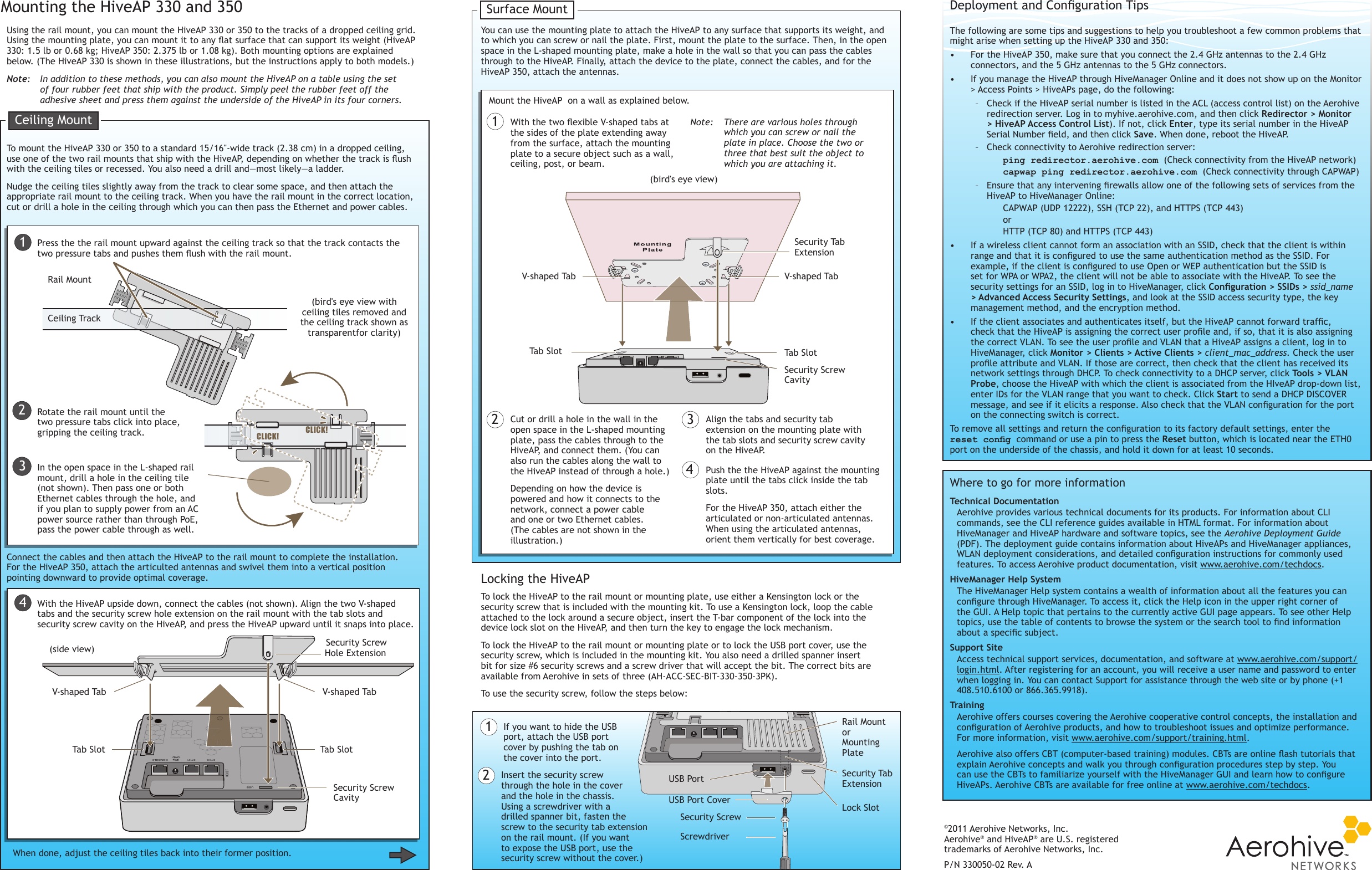
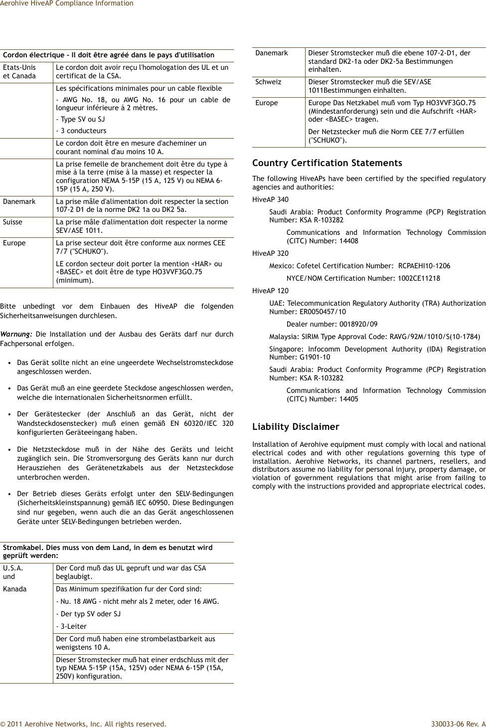
![Status LEDAerohive QuickStartfor the HiveAP 330 and 350This guide explains how to set up a HiveAP 330 or 350 so it can make a network connection to HiveManager, and how to mount it on a ceiling or wall. (The HiveAP 350 with articulated antennas is shown in the illustrations, but the instructions apply equally to the HiveAP 330 and to the HiveAP 350 with non-articulated antennas.) To register, get product documentation, and download software updates, visit www.aerohive.com/support.SwitchDHCP ServerFirewallInternetSome other network devices (They might all be incorporated in the same device, such as a router or rewall.)1Ethernet CableHiveAP 330 HiveAP 3502If the switch provides PoE (Power-over-Ethernet), cabling the HiveAP to the switch will cause the HiveAP to power on in a few seconds.If the switch does not provide PoE, use the AC/DC power adaptor (available as an accessory) to connect the HiveAP to a 100-240 AC power source.Eth0Connecting to HiveManagerUsing the Virtual Access ConsoleUsing your wireless client, scan for wireless networks. If you are within range, an SSID such as "AH-123456_ac" appears.Select it, and when prompted to enter a network key, type aerohive and then click Connect.BeaconsBeaconsWireless ClientConnect a standard Ethernet cable with RJ-45 connectors from ETH0 on the HiveAP to a switch.563P/N 330050-02 Rev. AAttach the 5 GHz antennas with gray rings to the 5 GHz connectors with gray circles...and the 2.4 GHz antennas with white rings to the 2.4 GHz connectors.Check the IP address of the default gateway that the DHCP server on the HiveAP assigned your client. Then make an SSH or Telnet connection to the HiveAP at that IP address. (Note that the Telnet connection is protected by WPA2 security mechanisms.) When prompted to enter your credentials, enter the default Aerohive login name (admin) and password (aerohive).C:\>ipcongWindows IP CongurationEthernet adapter Wireless Network Connection: Connection-specic DNS Sufx . : IP Address. . . . . . : 1.1.1.2 Subnet Mask . . . . . : 255.255.255.0 Default Gateway . . . : 1.1.1.1C:\>telnet 1.1.1.1After logging in to the virtual access console, you can view the status of various functions and make conguration changes. Here are some commonly used commands:Use these commands: To do the following:show interface Check the status of both wired and wireless interfacesshow interface mgt0 See the network settings (IP address, netmask, default gateway) and VLAN ID of the mgt0 interface, which is the management interface of the HiveAPno interface mgt0 dhcp client Disable the DHCP clientinterface mgt0 ip <ip_addr> <netmask>Set the IP address and netmask of the mgt0 interfaceinterface mgt0 native-vlan <id> Set the native (untagged) VLAN that the switch infrastructure in the surrounding wired and wireless network uses interface mgt0 vlan <id> Set the VLAN for management and control trafcshow capwap client See CAPWAP client settings and statusshow hive See the hive nameshow hive <string> neighbor Check for any neighboring hive membershive <string> ... Create a hive and set its parametersshow ssid See a list of all SSID namesssid <string> ... Congure an SSIDinterface { wi0 | wi1 } ssid <string>Bind an SSID to a wireless interface in access modesave cong Save the conguration to ashreboot Reboot the HiveAPOnly set the following command when managing HiveAPs through HiveManager or HiveManager Virtual Appliance. Do not use it with HiveManager Online.capwap client server name <string>Set the IP address or domain name of the CAPWAP server (HiveManager)To see a list of commands, and their accompanying CLI Help, type a question mark ( ? ). For example, to see all the show commands, enter show ?If you want to nd a command that uses a particular character or string of characters, you can do a search using the following command: show cmds | include <string>, where <string> is the word or string of characters you want to nd.Device- and platform-specic CLI reference guides are available online. (To learn how to access them, see "Where to go for more information" elsewhere in this document.)As explained in the previous section, after connecting a HiveAP to the network and powering it on, it acts as a DHCP client and tries to get its network settings automatically from a DHCP server in VLAN 1. However, if there is no DHCP server in that VLAN, if the native VLAN for the network segment is not 1, or if you just want to assign it a static IP address, then you need to access the CLI and dene the network settings yourself.One approach is to use a console cable, which is available from Aerohive as an accessory. Another is to use the virtual access console. This is a way of accessing the CLI on a HiveAP wirelessly through a special SSID that the HiveAP, by default, automatically activates for administrative access when it has no conguration and cannot reach its default gateway.The default virtual access console SSID name is “<hiveap-hostname>_ac”. The default host name of a HiveAP consists of "AH-" plus the last six digits of its MAC address; for example, AH-123456. In this case, the name of the default virtual access console SSID would be "AH-123456_ac". By default, this SSID uses aerohive as the PSK (preshared key) for authenticating user access. To access the virtual access console, do the following:By default, a HiveAP acts as a DHCP client and gets its network settings automatically from a DHCP server. (You can also congure it with static network settings through the CLI. See the next section, "Using the Virtual Access Console".) After a HiveAP has its network settings, it then acts as a CAPWAP client and sends CAPWAP Discovery messages until HiveManager, acting as the CAPWAP server, responds. CAPWAP (Control and Provisioning of Wireless Access Points) is a protocol that access points use to contact a management device and communicate with it.When a HiveAP goes online for the rst time without any specic CAPWAP server conguration entered manually or received as a DHCP option, it progresses through these cycle of CAPWAP connection attempts:A HiveAP connected directly to the network is called a portal. You can also place a HiveAP within radio range of a portal so that it forms a wireless link through the portal to the wired network. This kind of HiveAP is called a mesh point. A mesh point initially forms a hive with its portal using a default hive called hive0. Through this link, the mesh point can reach the network and get its network settings from the DHCP server. Then it can form a CAPWAP connection with HiveManager. (To add mesh points after changing the hive name, rst connect them to the wired network. Next, push the conguration with the new hive name and password to them from HiveManager. Finally, deploy them as mesh points.)If the HiveAP forms a CAPWAP connection with the Aerohive redirection server and its serial number has been entered in an ACL, the redirection server automatically redirects the CAPWAP connection to the corresponding HiveManager Online VHM (virtual HiveManager). The redirection server does this by sending the HiveAP the HiveManager domain name or IP address as its new CAPWAP server and the name of the appropriate VHM. If the HiveAP is currently using HTTP, the redirection server includes the conguration needed for the HiveAP to continue using it. Similarly, if the HiveAP is congured to access the public network through an HTTP proxy server, the redirection server saves the relevant settings on the HiveAP so it will continue using the HTTP proxy server when connecting to HiveManager.If the Aerohive redirection server does not have the HiveAP serial number, the ACL ignores the CAPWAP connection attempts, and the HiveAP repeats the connection cycle shown previously.After you cable the HiveAP to an Ethernet network and power it on, it automatically attempts to get its network settings through DHCP and contact HiveManager. The process typically takes about ve minutes to complete. If you see the HiveAP listed on the Monitor > Access Points > HiveAPs page in the HiveManager GUI, the initial setup is complete and you can now begin managing the HiveAP through HiveManager. If the HiveAP does not appear in the HiveManager GUI after about ten minutes, read the rest of this guide to understand how the HiveAP attempts to contact HiveManager and what you can do to help establish a connection between the two devices. (a) The HiveAP tries to connect to HiveManager using the default domain name "hivemanager. <local_domain>: 12222", where <local_domain> is the domain name that a DHCP server supplied to the HiveAP and 12222 is the UDP port number. If a DNS server has been congured to resolve that domain name to an IP address, the HiveAP and HiveManager then form a secure CAPWAP connection on port 12222. If the HiveAP cannot make a CAPWAP connection to HiveManager on port 12222, it tries to reach it by using TCP port 80: hivemanager.<local_domain>:80.(b) If the DNS server cannot resolve the domain name to an IP address, the HiveAP broadcasts CAPWAP Discovery messages on its local subnet. If HiveManager is on the local network and responds, they form a secure CAPWAP connection.(c) If the rst two searches for a local HiveManager produce no results, the HiveAP tries to contact HiveManager Online at redirector.aerohive.com:12222. If the Aerohive redirection server has a serial number or MAC address for that HiveAP in its ACL (access control list), it responds and they form a secure CAPWAP connection. If the HiveAP cannot make a CAPWAP connection to HiveManager Online on UDP port 12222, it tries to reach it on TCP port 80. If that proves unsuccessful, the HiveAP returns to its initial search through a DNS lookup and repeats the cycle. HiveManagerorHiveManager Virtual ApplianceHiveManager Onlineabc4The status LED in the corner of the HiveAP 330 and 350 indicates various states of activity through its color and illumination patterns (solid or ashing). The meanings of the colors are explained below.• Dark: There is no power or the status indicator is disabled.• Blue: (solid) The device is booting up or there is no backhaul link; (ashing) the device is shutting down• Green: The default route is through the backhaul Ethernet interface, but not all conditions for normal operations (white) have been met.• Yellow: The default route is through a backhaul wi interface, but not all conditions for normal operations (white) have been met.• White: The device is powered on and the rmware is operating normally; that is, a wireless interface in access mode is up, a wired or wireless backhaul link is up, and the HiveAP has a CAPWAP connection to HiveManager.• Purple: A new image is being loaded from HiveManager or a management AP.• Orange: An alarm indicating a rmware or hardware issue has occurred.You can adjust its brightness level from bright (the default) to soft to dim, or turn it off completely. In HiveManager, the setting is on the Conguration > Management Services > Management Options page. CLI: [ no ] system led brightness { soft | dim | off }.Bright Soft Dim Off](https://usermanual.wiki/Aerohive-Networks/HIVEAP350.User-Manual/User-Guide-1498751-Page-1.png)