Aerohive Networks HIVEAP350 Wireless Access Points User Manual Aerohive AP330 and AP350 User Guide

Aerohive Networks, Inc. Wireless Access Points Aerohive AP330 and AP350 User Guide

Contents

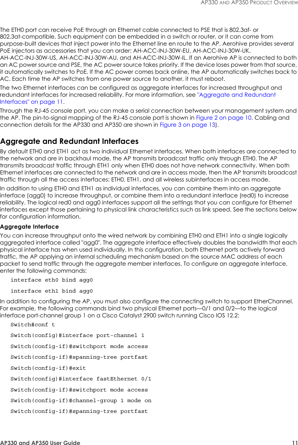
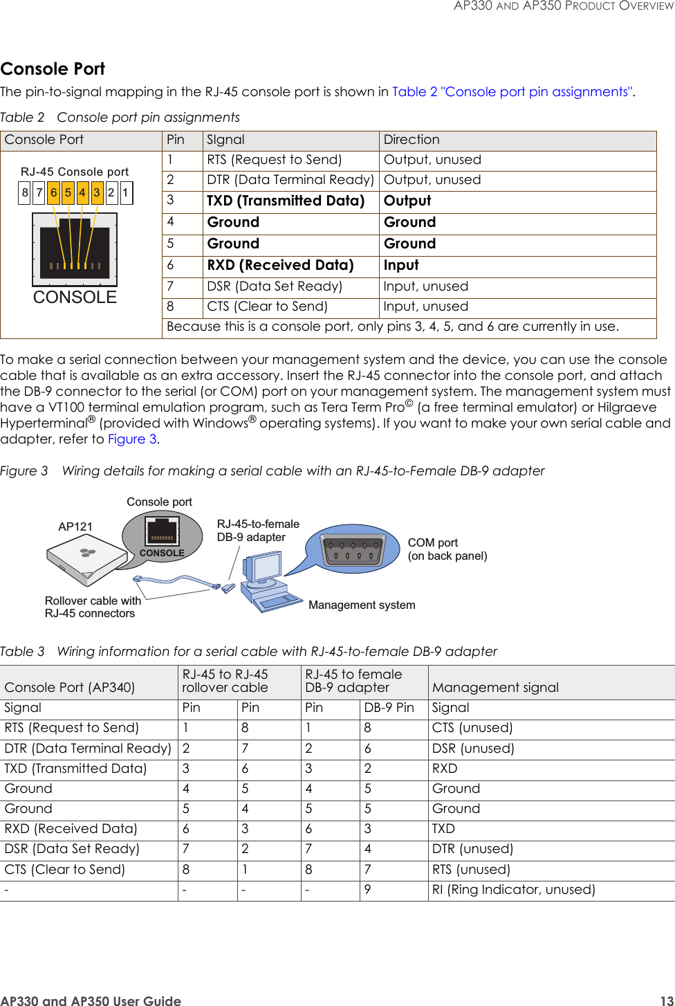
Aerohive_AP330-AP350-UserGuide Rev1
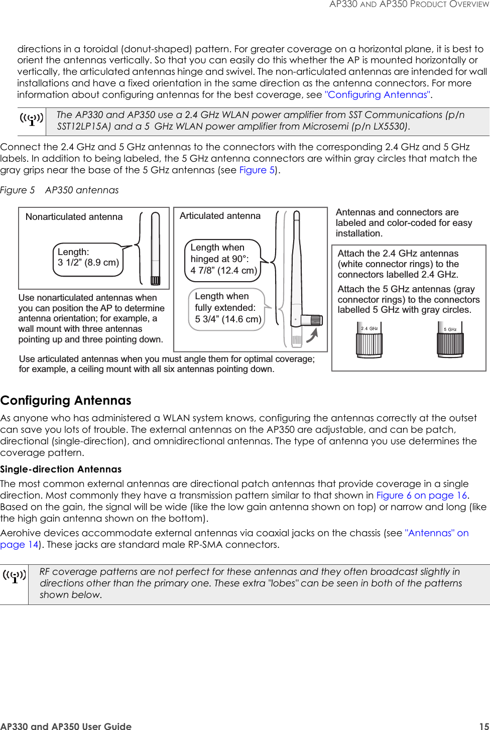
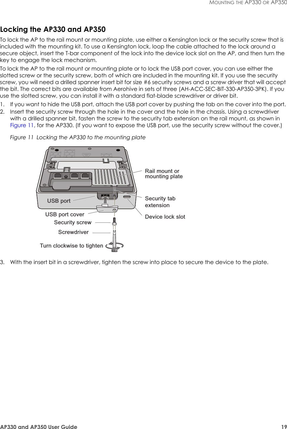
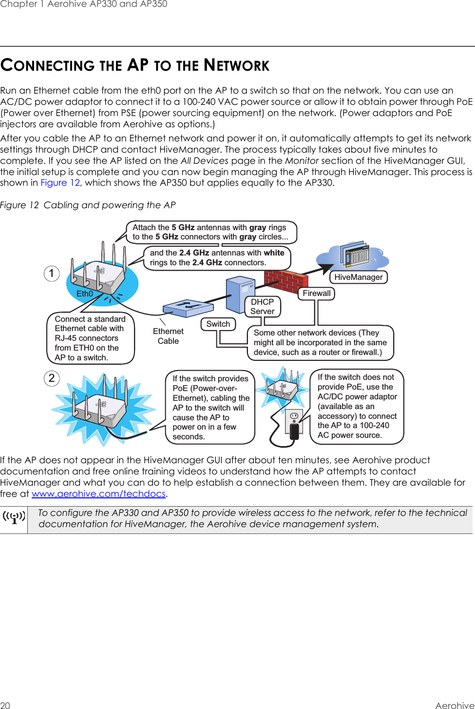
Aerohive AP330 and AP350 User Guide
3Aerohive AP330 and AP350 User GuideAerohive Technical PublicationsTo register, get the latest product documentation, see compliance information, and download software updates, visit www.aerohive.com/support.Copyright NoticeCopyright © 2012 Aerohive Networks, Inc. All rights reserved.Aerohive Networks, the Aerohive Networks logo, HiveOS, HiveAP, and HiveManager are trademarks of Aerohive Networks, Inc. All other trademarks and registered trademarks are the property of their respective companies.Information in this document is subject to change without notice. No part of this document may be reproduced or transmitted in any form or by any means, electronic or mechanical, for any purpose, without receiving written permission from:Aerohive Networks, Inc.330 Gibraltar DriveSunnyvale, CA 94089P/N 330092-01, Rev. A
4AerohiveAbout This GuideThis guide describes Aerohive AP330 and AP350 devices, including component descriptions, installation and mounting instructions, wiring diagrams, and hardware specifications.
AP330 and AP350 User Guide 5Contents Aerohive AP330 and AP350 ..................................................................................................... 7AP330 and AP350 Product Overview ..................................................................................... 8Ethernet and Console Ports............................................................................................. 10Aggregate and Redundant Interfaces .................................................................. 11Console Port ............................................................................................................... 13USB Modem Port............................................................................................................... 14Status Indicator................................................................................................................. 14Antennas ........................................................................................................................... 14Configuring Antennas ............................................................................................... 15Mounting the AP330 or AP350............................................................................................... 17Ceiling Mount ...................................................................................................................17Surface Mount .................................................................................................................. 18Locking the AP330 and AP350 ................................................................................. 19Connecting the AP to the Network ...................................................................................... 20Device, Power, and Environmental Specifications............................................................. 21Index ......................................................................................................................................... 23
Contents6Aerohive
AP330 and AP350 User Guide 7Aerohive AP330 and AP350The AP330 and AP350 are 802.11n wireless access points designed for greater throughput and range, with the added capability of being configured as routers. They provide dual concurrent 802.11b/g/n and 802.11a/n radios for 3x3 MIMO (Multiple Input Multiple Output) antenna configurations and three spatial streams. When you enable 802.11n high-throughput options such as wide-channel mode (40-MHz channels), A-MPDU and A-MSDU packet aggregation, short guard interval, and MCS23 data rates, they can provide a PHY data rate up to 450 Mbps per radio. The AP330 has internal antennas, and the AP350 has detachable external antennas. They both have dual 10/100/1000 Ethernet ports for link aggregation or link redundancy. Their systems can accept power from either an 802.3af or 802.3at standard PoE (Power over Ethernet) power injector or from an AC/DC power adapter connected to a 100-240 VAC input power source. This chapter covers the following topics relating to the AP330 and AP350:•"AP330 and AP350 Product Overview" on page 8•"Ethernet and Console Ports" on page 10•"Status Indicator" on page 14•"Antennas" on page 14•"Mounting the AP330 or AP350" on page 17•"Device, Power, and Environmental Specifications" on page 21
Chapter 1 Aerohive AP330 and AP3508AerohiveAP330 AND AP350 PRODUCT OVERVIEWThe AP330 and AP350 models provide excellent throughput and coverage. The AP330 has internal antennas, and the AP350 has detachable external antennas. You can see the hardware components on the AP in Figure 1. Each component is described in Table 1 "AP330 and AP350 component descriptions".Figure 1  AP330 and AP350 hardware componentsTable 1  AP330 and AP350 component descriptionsComponent DescriptionStatus Indicator The status indicator conveys operational states for system power, firmware updates, Ethernet and wireless interface activity, and major alarms. For details, see "Status Indicator" on page 14.2.4 and 5 GHz RP-SMA connectors (AP350)You can connect up to six detachable single-band antennas to the male 802.11a/b/g/n RP-SMA (reverse polarity-subminiature version A) connectors. Connect the antennas that have white ribbed rings and are labelled 2.4 GHz to the connectors that are labelled 2.4 GHz. Connect the antennas that have gray knurled rings and are labelled 5 GHz to the connectors that are labelled 5 GHz and are encircled by a gray line. For details, see "Antennas" on page 14.Console port You can access the CLI by making a serial connection to the RJ-45 console port. The management station from which you connect to the device must have a VT100 emulation program, such as Tera Term Pro© (a free terminal emulator) or Hilgraeve Hyperterminal® (provided with Windows® operating systems from Windows 95 to Windows XP). The following are the serial connection settings: bits per second: 9600, data bits: 8, parity: none, stop bits: 1, flow control: none. For details, see "Ethernet and Console Ports" on page 10.AP330 AP350Status indicatorRP-SMA connectors for 2.4 and 5 GHz antennasAP330 and AP350 underside (identical for both devices)ResetSecurity tab cavityDevice lock slotSecurity screw holeUSB port10/100/1000Mbps Ethernet ports(PoE on ETH0)Power connectorConsole portStatus indicator
AP330 and AP350 User Guide 9AP330 AND AP350 PRODUCT OVERVIEWPower Connector The 12-volt DC power connector (2.0 amps) is one of two methods through which you can power the AP330 and AP350. To connect it to a 100 – 240-volt AC power source, use the AC/DC power adaptor that is available as an extra option. Because the AP does not have an on/off switch, connecting it to a power source automatically powers on the device.ETH0 10/100/1000 Mbps PoE Portand ETH1 10/100/1000 Mbps PortThe two 10/100/1000-Mbps Ethernet ports—ETH0 and ETH1—receive RJ-45 connectors. The AP can receive power through an Ethernet connection to the ETH0 port from PSE (power sourcing equipment) that is compatible with the 802.3af and 802.3at standards. Aerohive provides suitable PoE injectors as an optional accessory. (If you connect the AP to a power source through the power connector and the ETH0 PoE port simultaneously, the device draws power through the power connector and automatically disables PoE.)You can configure ETH0 and ETH1 as two individual Ethernet interfaces, combine them into an aggregate interface to increase throughput, or combine them into a redundant interface to increase reliability. Using bridging, you can connect the AP330 or AP350 to a wired network or a wired device (such as a security camera) through these ports. They are compatible with 10/100/1000Base-T/TX and automatically negotiate half- and full-duplex connections with the connecting device. They are autosensing and adjust to straight-through and cross-over Ethernet cables automatically. For details, see "Ethernet and Console Ports" on page 10.Reset Button The reset button allows you to reboot the device or reset the AP to its factory default settings. Insert a paper clip, or something similar, into the Reset pinhole and press the reset button. To reboot the device, hold the button down for 5 seconds. To return the configuration to the factory default settings, hold it down for at least 10 seconds. After releasing the button, the Power LED goes dark, and then glows steady amber while the firmware loads and the system performs a self-test. After the software finishes loading, the Power LED glows steady green.To disable the reset button from resetting the configuration, enter this command: no reset-button reset-config-enable Pressing the button for 5 seconds will still reboot the AP, but pressing it for more than 10 seconds will not reset its configuration.USB Port The Type-A USB 2.0 port (backward compatible with USB1.1) allows you to connect a wireless 3G/4G USB modem to serve as a backup WAN connection. For locations where an Ethernet connection to the WAN is not possible, you can use the USB modem as the primary (and only) interface to the WAN.For specific information about the modems supported for AP330 and AP350 devices, and configuration settings, refer to HiveManager Help.Security Tab Cavity and HoleWhen mounting the AP on a ceiling track or flat surface, insert the security tab extension on the rail mount or mounting plate into the security tab cavity and then fasten the AP to the mounting equipment by inserting the security screw through the security screw hole and tightening it. If you want to hide the USB port, insert the USB port cover into the port before fastening the AP to the rail mount or mounting plate. See "Locking the AP330 and AP350" on page 19.Device Lock Slot You can physically secure the AP by attaching a lock and cable (such as a Kensington® notebook lock) to the device lock slot.Table 1  AP330 and AP350 component descriptions (Continued)Component Description
Chapter 1 Aerohive AP330 and AP35010 AerohiveEthernet and Console PortsThere are three ports on the AP330 and AP350: two RJ-45 10/100/1000Base-T/TX Ethernet ports and an RJ-45 console port.The pin assignments in the Ethernet ports follow the TIA/EIA-568-B standard (see Figure 2). The ports accept standard types of Ethernet cable—cat3, cat5, cat5e, or cat6. Because the ports have autosensing capabilities, the wiring termination in the Ethernet cable can be either straight-through or cross-over.Figure 2  PoE wire usage and pin assignmentsETH0Pin T568A Wire Color1 White/Green2 Green3 White/Orange4Blue5 White/Blue6 Orange7 White/Brown8Brown(View of the ETH0 PoE Port)8 1Pin numbersPin T568B Wire Color1 White/Orange2 Orange3 White/Green4Blue5 White/Blue6 Green7 White/Brown8BrownT568A-terminated Ethernet cable with an RJ-45 connectorData Signal802.3af Alternative A (data and power on the same wires)802.3af Alternative B (data and power on separate wires) 802.3at wring optionsPin MDI MDI-X MDI or MDI-X 1 2 3 41 Transmit + DC+ DC– – – – DC1+ DC1– DC1+ DC1–2 Transmit - DC+ DC– – – – DC1+ DC1– DC1+ DC1–3 Receive + DC– DC+ – – – DC1– DC1+ DC1– DC1+4 (unused) – – – – – – DC+ DC2+ DC2+ DC2– DC2–5 (unused) – – – – – – DC+ DC2+ DC2+ DC2– DC2–6 Receive - DC–  DC+ – – – DC1– DC1+ DC1– DC1+7 (unused) – – – – – – DC– DC2– DC2– DC2+ DC2+8 (unused) – – – – – – DC– DC2– DC2– DC2+ DC2+MDI = Medium dependent interface for straight-through connectionsMDI-X = Medium dependent interface for cross-over (X) connectionsThe Eth0 PoE port is auto-sensing and can automatically adjust to transmit and receive data over straight-through or cross-over Ethernet connections. Likewise, it can automatically adjust to 802.3af Alternative A and B power delivery methods. Furthermore, when the Alternative A method is used, the port automatically allows for polarity reversals depending on their role as either MDI or MDI-X. In 802.3at, the 1/2 and 3/6 wire pairs connect to DC source 1 and 4/5 and 7/8 pairs to DC source 2 in PSE. Although the exact polarity depends on the PSE design, the Eth0 PoE port can support all possible options.T568B-terminated Ethernet cable with an RJ-45 connectorT568A and T568B are two standard wiring termination schemes. Note that the only difference between them is that the white/green + solid green pair of wires and the white/orange + solid orange pair are reversed.For straight-through Ethernet cables—using either the T568A or T568B standard—the eight wires terminate at the same pins on each end.For cross-over Ethernet cables, the wires terminate at one end according to the T568A standard and at the other according to T568B.
AP330 and AP350 User Guide 11AP330 AND AP350 PRODUCT OVERVIEWThe ETH0 port can receive PoE through an Ethernet cable connected to PSE that is 802.3af- or 802.3at-compatible. Such equipment can be embedded in a switch or router, or it can come from purpose-built devices that inject power into the Ethernet line en route to the AP. Aerohive provides several PoE injectors as accessories that you can order: AH-ACC-INJ-30W-EU, AH-ACC-INJ-30W-UK, AH-ACC-INJ-30W-US, AH-ACC-INJ-30W-AU, and AH-ACC-INJ-30W-IL. If an Aerohive AP is connected to both an AC power source and PSE, the AC power source takes priority. If the device loses power from that source, it automatically switches to PoE. If the AC power comes back online, the AP automatically switches back to AC. Each time the AP switches from one power source to another, it must reboot.The two Ethernet interfaces can be configured as aggregate interfaces for increased throughput and redundant interfaces for increased reliability. For more information, see "Aggregate and Redundant Interfaces" on page 11.Through the RJ-45 console port, you can make a serial connection between your management system and the AP. The pin-to-signal mapping of the RJ-45 console port is shown in Figure 2 on page 10. Cabling and connection details for the AP330 and AP350 are shown in Figure 3 on page 13).Aggregate and Redundant InterfacesBy default ETH0 and ETH1 act as two individual Ethernet interfaces. When both interfaces are connected to the network and are in backhaul mode, the AP transmits broadcast traffic only through ETH0. The AP transmits broadcast traffic through ETH1 only when ETH0 does not have network connectivity. When both Ethernet interfaces are connected to the network and are in access mode, then the AP transmits broadcast traffic through all the access interfaces: ETH0, ETH1, and all wireless subinterfaces in access mode.In addition to using ETH0 and ETH1 as individual interfaces, you can combine them into an aggregate interface (agg0) to increase throughput, or combine them into a redundant interface (red0) to increase reliability. The logical red0 and agg0 interfaces support all the settings that you can configure for Ethernet interfaces except those pertaining to physical link characteristics such as link speed. See the sections below for configuration information.Aggregate InterfaceYou can increase throughput onto the wired network by combining ETH0 and ETH1 into a single logically aggregated interface called "agg0". The aggregate interface effectively doubles the bandwidth that each physical interface has when used individually. In this configuration, both Ethernet ports actively forward traffic, the AP applying an internal scheduling mechanism based on the source MAC address of each packet to send traffic through the aggregate member interfaces. To configure an aggregate interface, enter the following commands:interface eth0 bind agg0interface eth1 bind agg0In addition to configuring the AP, you must also configure the connecting switch to support EtherChannel. For example, the following commands bind two physical Ethernet ports—0/1 and 0/2—to the logical interface port-channel group 1 on a Cisco Catalyst 2900 switch running Cisco IOS 12.2:Switch#conf tSwitch(config)#interface port-channel 1Switch(config-if)#switchport mode accessSwitch(config-if)#spanning-tree portfastSwitch(config-if)#exitSwitch(config)#interface fastEthernet 0/1Switch(config-if)#switchport mode accessSwitch(config-if)#channel-group 1 mode onSwitch(config-if)#spanning-tree portfast
Chapter 1 Aerohive AP330 and AP35012 AerohiveSwitch(config-if)#exitSwitch(config)#int fastEthernet 0/2Switch(config-if)#switchport mode accessSwitch(config-if)#channel-group 1 mode onSwitch(config-if)#spanning-tree portfastSwitch(config-if)#exitSwitch(config)#exitSwitch#wr memFinally, you must cable the Cisco switch and the AP together: Cisco 0/1 to AP eth0, and Cisco 0/2 to AP eth1.Redundant InterfaceIf a single Ethernet link provides sufficient bandwidth and speed, such as a 1000 Mbps link, but you want to ensure link redundancy, you can connect the two Ethernet ports to the same switch—or to two different switches—and configure them to act as a redundant interface called "red0". In this mode, only one Ethernet interface is actively forwarding traffic at any one time. If eth0 is active and eth1 is passive and eth0 loses its connection, the AP switches over to eth1. To configure a redundant interface, enter the following commands:interface eth0 bind red0 primaryinterface eth1 bind red0The interface that you specify as primary is the one that the AP uses when both interfaces have network connectivity. Because the AP uses eth0 as the primary interface by default, it is unnecessary to specify "primary" in the first command above. However, it is included to make the role of eth0 as the primary interface obvious. Interface Selection for the Default RouteIn cases where there are multiple active interfaces in backhaul mode, the AP uses the following logic to choose which interface to use in its default route: • If there is an Ethernet interface and a wireless interface in backhaul mode, the AP uses the Ethernet interface in its default route.• If there are multiple Ethernet interfaces in backhaul mode, the AP chooses which one to use in its default route in the following order:• It uses red0 or agg0 if either has at least one member interface bound to it and its link state is UP.• It uses ETH0 if neither red0 nor agg0 has any member interfaces and the link state for ETH0 is UP.• It uses ETH1 if neither red0 nor agg0 has any member interfaces, the link state for ETH0 is DOWN, and the link state for ETH1 is UP.No extra configuration is necessary on the connecting switch or switches to support a redundant interface.
AP330 and AP350 User Guide 13AP330 AND AP350 PRODUCT OVERVIEWConsole PortThe pin-to-signal mapping in the RJ-45 console port is shown in Table 2 "Console port pin assignments".To make a serial connection between your management system and the device, you can use the console cable that is available as an extra accessory. Insert the RJ-45 connector into the console port, and attach the DB-9 connector to the serial (or COM) port on your management system. The management system must have a VT100 terminal emulation program, such as Tera Term Pro© (a free terminal emulator) or Hilgraeve Hyperterminal® (provided with Windows® operating systems). If you want to make your own serial cable and adapter, refer to Figure 3.Figure 3  Wiring details for making a serial cable with an RJ-45-to-Female DB-9 adapterTable 2  Console port pin assignmentsConsole Port Pin SIgnal Direction1 RTS (Request to Send) Output, unused2 DTR (Data Terminal Ready) Output, unused3TXD (Transmitted Data) Output4Ground Ground5Ground Ground6RXD (Received Data) Input7 DSR (Data Set Ready) Input, unused8 CTS (Clear to Send) Input, unusedBecause this is a console port, only pins 3, 4, 5, and 6 are currently in use.Table 3  Wiring information for a serial cable with RJ-45-to-female DB-9 adapterConsole Port (AP340)RJ-45 to RJ-45 rollover cableRJ-45 to female DB-9 adapter Management signalSignal Pin Pin Pin DB-9 Pin SignalRTS (Request to Send) 1 8 1 8 CTS (unused)DTR (Data Terminal Ready) 2 7 2 6 DSR (unused)TXD (Transmitted Data) 3 6 3 2 RXDGround 4 5 4 5 GroundGround 5 4 5 5 GroundRXD (Received Data) 6 3 6 3 TXDDSR (Data Set Ready) 7 2 7 4 DTR (unused)CTS (Clear to Send) 8 1 8 7 RTS (unused)- - - - 9 RI (Ring Indicator, unused)CONSOLE8  7  6  5  4  3  2  1RJ-45 Console portRollover cable with RJ-45 connectorsRJ-45-to-female DB-9 adapterConsole portCOM port (on back panel)CONSOLEManagement systemAP121
Chapter 1 Aerohive AP330 and AP35014 AerohiveUSB Modem PortWhen configured as routers, AP330 and AP350 devices can use a wireless USB modem for a WAN connection. The typical use of the USB modem is to act as a backup to the ETH0/WAN interface; however, for locations where an Ethernet connection to the WAN is not possible, you can use the USB modem as the primary (and only) interface to the WAN.Status IndicatorThe status indicator appears in the triangular region on the top surface of the AP330 and AP350. It is illuminated by various colors to indicate different states of activity. The meanings of the colors are as follows:•Dark: There is no power or the status indicator is disabled.•Blue: (solid) The device is booting up or there is no backhaul link; (flashing) the device is shutting down.•Green: The default route is through the backhaul Ethernet interface, but not all conditions for normal operations (white) have been met.•Yellow: The default route is through a backhaul wifi interface, but not all conditions for normal operations (white) have been met.•White: The device is powered on and the firmware is operating normally; that is, the AP has made a CAPWAP connection to HiveManager.•Purple: A new image is being loaded from HiveManager.•Orange: An alarm indicating a firmware or hardware issue has occurred.For locations where the status indicator might be a distraction or attract unwanted attention, you can adjust its brightness level from bright (the default) to soft to dim. You can even turn it off completely. In HiveManager, choose the brightness level that you want from the LED Brightness drop-down list on the Configuration > Advanced Configuration > Management Services > Management Options page. Through the CLI, enter [ no ] system led brightness { soft | dim | off }. The various brightness levels are shown in Figure 4. (Although the AP330 is shown in the illustration, the same settings also apply to the AP350.)Figure 4  Status indicator brightness levelsAntennasThe AP330 has internal antennas, and the AP350 connects to detachable ones. Antennas for both models are described below.AP330The AP330 has six internal single-band antennas with 50-ohm impedance. Three of the antennas operate in the 2.4 GHz band (IEEE 802.11b/g/n) and have a 4-dBi peak gain. The other three antennas operate in the 5 GHz band (IEEE 802.11a/n) and have a 6-dBi peak gain. All antennas are omnidirectional and provide fairly equal coverage in all directions.AP350The AP350 has six male 802.11a/b/g/n RP-SMA (reverse polarity-subminiature version A) connectors for attaching external up to six single-band dipole antennas. Articulated and non-articulated antennas are available as accessories. The articulated 2.4 GHz and 5 GHz antennas have a 4-dBi gain. The non-articulated 2.4 GHz and 5 GHz antennas have a 2-dBi gain. The impedance for both types of antennas is 50 ohms. These antennas are omnidirectional, providing fairly equal coverage in all When using a wireless USB modem on an AP330 or AP350, you must connect it to an AC power source instead of using PoE to power the device. Bright Soft Dim Off
AP330 and AP350 User Guide 15AP330 AND AP350 PRODUCT OVERVIEWdirections in a toroidal (donut-shaped) pattern. For greater coverage on a horizontal plane, it is best to orient the antennas vertically. So that you can easily do this whether the AP is mounted horizontally or vertically, the articulated antennas hinge and swivel. The non-articulated antennas are intended for wall installations and have a fixed orientation in the same direction as the antenna connectors. For more information about configuring antennas for the best coverage, see "Configuring Antennas".Connect the 2.4 GHz and 5 GHz antennas to the connectors with the corresponding 2.4 GHz and 5 GHz labels. In addition to being labeled, the 5 GHz antenna connectors are within gray circles that match the gray grips near the base of the 5 GHz antennas (see Figure 5).Figure 5  AP350 antennasConfiguring AntennasAs anyone who has administered a WLAN system knows, configuring the antennas correctly at the outset can save you lots of trouble. The external antennas on the AP350 are adjustable, and can be patch, directional (single-direction), and omnidirectional antennas. The type of antenna you use determines the coverage pattern. Single-direction AntennasThe most common external antennas are directional patch antennas that provide coverage in a single direction. Most commonly they have a transmission pattern similar to that shown in Figure 6 on page 16. Based on the gain, the signal will be wide (like the low gain antenna shown on top) or narrow and long (like the high gain antenna shown on the bottom).Aerohive devices accommodate external antennas via coaxial jacks on the chassis (see "Antennas" on page 14). These jacks are standard male RP-SMA connectors.The AP330 and AP350 use a 2.4 GHz WLAN power amplifier from SST Communications (p/n SST12LP15A) and a 5 GHz WLAN power amplifier from Microsemi (p/n LX5530).RF coverage patterns are not perfect for these antennas and they often broadcast slightly in directions other than the primary one. These extra "lobes" can be seen in both of the patterns shown below.Nonarticulated antenna Articulated antennaLength when  fully extended: 5 3/4” (14.6 cm)Length when hinged at 90°: 4 7/8” (12.4 cm)Length:3 1/2” (8.9 cm)Attach the 2.4 GHz antennas (white connector rings) to the connectors labelled 2.4 GHz.Attach the 5 GHz antennas (gray connector rings) to the connectors labelled 5 GHz with gray circles.Use articulated antennas when you must angle them for optimal coverage; for example, a ceiling mount with all six antennas pointing down.Use nonarticulated antennas when you can position the AP to determine antenna orientation; for example, a wall mount with three antennas pointing up and three pointing down. Antennas and connectors are labeled and color-coded for easy installation.
Chapter 1 Aerohive AP330 and AP35016 AerohiveFigure 6  Directional antenna patternsOmnidirectional AntennasYou typically orient omnidirectional antennas vertically, positioning them on all devices in the same direction. Omnidirectional antennas create coverage areas that can be toroidal (doughnut-shaped) or cardioid (heart- or plum-shaped), broadcasting to the sides much more effectively than up or down (see Figure 7). In general, this is good for most office environments because you have large flat floors. However, it can be a problem in environments with high ceilings.Figure 7  Omnidirectional antenna radiation patternsHigher gainLower gain(Bird’s eye view)Patch antennasHigher gainToroidal pattern                                                                 Cardioid pattern
AP330 and AP350 User Guide 17MOUNTING THE AP330 OR AP350MOUNTING THE AP330 OR AP350Using the mounting plate and track clip, you can mount the AP330 or AP350 to the tracks of a dropped ceiling grid. Using just the mounting plate, you can mount the AP to any surface that can support its weight (AP330: 1.5 lb., 0.68 kg; AP330: 2.375 lb. (1.08 kg)).Ceiling MountTo mount the AP330 or AP350 to a track in a dropped ceiling, use one of the two rail mounts that ship with the product, depending on whether the ceiling track is flush with the ceiling tiles or recessed:• 15/16" flush ceiling rail mount• 15/16" recessed ceiling rail mountIf necessary, nudge the adjacent ceiling tiles slightly away from the track to clear some space. Attach the appropriate rail mount to the track, drill a hole in the ceiling tile, and then attach the power and Ethernet cables to the AP, as shown in Figure 8.Figure 8  Attaching the rail mount to a ceiling trackWith the AP upside down, align the two flexible V-shaped tabs and the security tab extension on the rail mount with the two tab slots and the security screw cavity on the underside of the AP, and then push the AP upward until it clicks into place as shown in Figure 9 on page 18.For narrower tracks, you can order a pair of 9/16" rail mounts from Aerohive (AH-ACC-9-16-CLIP-330-AP350). One rail mount in the pair is flush and the other is recessed.You can slide the rail mount along the ceiling track if you need to adjust its location.Press the rail mount against the ceiling track so that the track contacts the two pressure tabs and pushes them flush with the rail mount.(Bird’s eye view with the ceiling tiles removed and the ceiling track shown as transparent for clarity)Rotate the rail mount until the two pressure tabs click into place, gripping the ceiling track.2In the open space not covered by the L-shaped rail mount, drill a hole in the ceiling tile (not shown). Then pass one or both Ethernet cables through the hole, and if you plan to supply power from an AC power source rather than through PoE, pass the power cable through as well. Finally, connect the cables to the AP.31Rail mountCeiling trackCLICK!CLICK!
Chapter 1 Aerohive AP330 and AP35018 AerohiveFigure 9  Attaching the AP to the rail mountFor the AP350, attach the articulated antennas and swivel them into a vertical position pointing downward to provide optimal coverage. When done, adjust the ceiling tiles back into their former position.Surface MountYou can use the flat mounting plate to attach the AP330 or AP350 to any surface that supports its weight (AP330: 1.5 lb or 0.68 kg; AP350: 2.375 lb or 1.08 kg), and to which you can screw or nail the plate. First, mount the plate to the surface, and then attach the device to the plate, as shown in Figure 10.Figure 10  Mounting the AP on a wallWith the AP upside down, align the two V-shaped tabs and the security tab extension on the rail mount with the tab slots and security screw cavity on the AP, and press the AP upward until it snaps into place.3Security tab extension Security screw cavityTab slotTab slotV-shaped tabV-shaped tab(side view)Security screw cavityTab slotTab slotSecurity tab extension V-shapedtabV-shaped tab(Bird’s eye view)231With the two flexible V-shaped tabs at the sides of the plate extending away from the surface, attach the mounging plate to a secure object such as a wall, ceiling, post, or beam.Cut or drill a hole in the space not covered by the L-shaped mounting plate, pass the cables through to the AP, and connect them. (You can also run the cables along the wall to the AP instead of through a hole.)Depending on how the device is powered and how it connects to the network, connect a power cable and one or two Ethernet cables. (The cables are not shown in this illustration.)Align the tabs and security tab extension on the mounting plate with the tab slots and security screw cavity on the AP.Push the AP against the mounting plate until the tabs click inside the tab slots.4
AP330 and AP350 User Guide 19MOUNTING THE AP330 OR AP350Locking the AP330 and AP350To lock the AP to the rail mount or mounting plate, use either a Kensington lock or the security screw that is included with the mounting kit. To use a Kensington lock, loop the cable attached to the lock around a secure object, insert the T-bar component of the lock into the device lock slot on the AP, and then turn the key to engage the lock mechanism. To lock the AP to the rail mount or mounting plate or to lock the USB port cover, you can use either the slotted screw or the security screw, both of which are included in the mounting kit. If you use the security screw, you will need a drilled spanner insert bit for size #6 security screws and a screw driver that will accept the bit. The correct bits are available from Aerohive in sets of three (AH-ACC-SEC-BIT-330-AP350-3PK). If you use the slotted screw, you can install it with a standard flat-blade screwdriver or driver bit.1. If you want to hide the USB port, attach the USB port cover by pushing the tab on the cover into the port. 2. Insert the security screw through the hole in the cover and the hole in the chassis. Using a screwdriver with a drilled spanner bit, fasten the screw to the security tab extension on the rail mount, as shown in Figure 11, for the AP330. (If you want to expose the USB port, use the security screw without the cover.)Figure 11  Locking the AP330 to the mounting plate3. With the insert bit in a screwdriver, tighten the screw into place to secure the device to the plate.Turn clockwise to tightenUSB portUSB port coverSecurity screwDevice lock slotRail mount or mounting plateScrewdriverSecurity tab extension
Chapter 1 Aerohive AP330 and AP35020 AerohiveCONNECTING THE AP TO THE NETWORKRun an Ethernet cable from the eth0 port on the AP to a switch so that on the network. You can use an AC/DC power adaptor to connect it to a 100-240 VAC power source or allow it to obtain power through PoE (Power over Ethernet) from PSE (power sourcing equipment) on the network. (Power adaptors and PoE injectors are available from Aerohive as options.)After you cable the AP to an Ethernet network and power it on, it automatically attempts to get its network settings through DHCP and contact HiveManager. The process typically takes about five minutes to complete. If you see the AP listed on the All Devices page in the Monitor section of the HiveManager GUI, the initial setup is complete and you can now begin managing the AP through HiveManager. This process is shown in Figure 12, which shows the AP350 but applies equally to the AP330.Figure 12  Cabling and powering the APIf the AP does not appear in the HiveManager GUI after about ten minutes, see Aerohive product documentation and free online training videos to understand how the AP attempts to contact HiveManager and what you can do to help establish a connection between them. They are available for free at www.aerohive.com/techdocs.To configure the AP330 and AP350 to provide wireless access to the network, refer to the technical documentation for HiveManager, the Aerohive device management system. Attach the 5 GHz antennas with gray rings to the 5 GHz connectors with gray circles...Connect a standard Ethernet cable with RJ-45 connectors from ETH0 on the AP to a switch.If the switch provides PoE (Power-over-Ethernet), cabling the AP to the switch will cause the AP to power on in a few seconds.Some other network devices (They might all be incorporated in the same device, such as a router or firewall.)SwitchEth0 FirewallDHCP ServerEthernet CableIf the switch does not provide PoE, use the AC/DC power adaptor (available as an accessory) to connect the AP to a 100-240 AC power source.and the 2.4 GHz antennas with white rings to the 2.4 GHz connectors.12HiveManager
AP330 and AP350 User Guide 21DEVICE, POWER, AND ENVIRONMENTAL SPECIFICATIONSDEVICE, POWER, AND ENVIRONMENTAL SPECIFICATIONSUnderstanding the range of specifications for the AP330 and AP350 is necessary for optimal deployment and device operation. The following specifications describe the physical features and hardware components, the power adapter and PoE (Power over Ethernet) electrical requirements, and the temperature and humidity ranges in which the devices can operate.Device Specifications• Chassis dimensions: 6 7/8" W x 1 5/8" H x 6 7/8" D (17.4 cm W x 4.1 cm H x 17.4 cm D)•Weight• AP330 1.5 lb. (0.68 kg)• AP350 2.375 lb. (1.08 kg)• Antennas: Three omnidirectional 802.11b/g/n antennas, and three omnidirectional 802.11a/n antennas• Serial port: RJ-45 (bits per second: 9600, data bits: 8, parity: none, stop bits: 1, flow control: none)• Ethernet ports • Eth0: autosensing 10/100/1000Base-T/TX Mbps, with IEEE 802.3af- and 802.3at-compliant PoE (Power over Ethernet)• Eth1: autosensing 10/100/1000Base-T/TX Mbps (no PoE support)Power Specifications• AC/DC power adapter:• Input:100 – 240 VAC• Output: 12V/2.0.A• PoE nominal input voltages: 48 V• RJ-45 power input pins: Wires 4, 5, 7, 8 or 1, 2, 3, 6Environmental Specifications• AP330• Operating temperature: 32 to 104 degrees F (0 to 40 degrees C)• Storage temperature: -40 to 185 degrees F (-40 to 85 degrees C)• Relative Humidity: Maximum 95% noncondensing• AP350• Operating temperature: -4 to 131 degrees F (-20 to 55 degrees C)• Storage temperature: -40 to 185 degrees F (-40 to 85 degrees C)• Relative Humidity: Maximum 95% (noncondensing)
Chapter 1 Aerohive AP330 and AP35022 Aerohive
AP330 and AP350 User Guide 23Index IndexAaggregate interface 11antennasarticulated and non-articulated, AP350 14configuring 15connectors, AP350 8directional 16internal, AP330 14omnidirectional 16patch 15single-direction 15AP330 7–21antennas 14antennas, internal 14console 8, 11, 13, 21environmental specifications 21Ethernet port 9, 21Ethernet ports 10, 11gain 14impedance 14LED brightness control 14locking 9, 19mounting, ceiling 17mounting, surface 18PoE 9, 11, 20power connector 9power specifications 21reset button 9security screw cavity 17security tab cavity 9status indicator 8, 14USB modem connector 9WLAN power amplifier 15AP350 7–21antenna connectors 8antennas 14antennas, articulated and non-articulated 14console 8, 11, 13, 21environmental specifications 21Ethernet port 9, 21Ethernet ports 10, 11gain 14impedence 14LED brightness control 14locking 9, 19mounting, ceiling 17mounting, surface 18PoE 9, 11, 20power connector 9power specifications 21reset button 9security screw cavity 17security tab cavity 9status indicator 8, 14USB modem connector 9WLAN power amplifier 15CCLIresetting the configuration 9connecting to network 20console, See individual platform entriesDDHCP 20Iinterfacesaggregate 11redundant 12Nnetwork connection 20PPoE 20PSE 20Rreboot, APs 9redundant interfaces 12reset config 9RF coverage patterns 15directional antennas 16omnidirectional antennas 16routes, default route selection 12Sserial port, See individual platform entriesUUSB modem connector 9
Index 24 Aerohive
© 2011 Aerohive Networks, Inc. All rights reserved.  330033-06 Rev. AAerohive HiveAP Compliance InformationFederal Communication Commission Interference StatementAerohive products that show an FCC identifier on the product label(FCC ID: WBV-<model_name>) comply with part 15 of the FCC Ruleswhen operating under the following restrictions: (1) they do not causeharmful interference, and (2) they must accept any RF interferencereceived, including interference that might cause an unwanted impacton their operation.This equipment has been tested and found to comply with the limits fora Class B digital device, pursuant to Part 15 of the FCC Rules. Theselimits are designed to provide reasonable protection against harmfulinterference in a residential installation. This equipment generates,uses and can radiate radio frequency energy and, if not installed andused in accordance with the instructions, may cause harmfulinterference to radio communications. However, there is no guaranteethat interference will not occur in a particular installation. If thisequipment does cause harmful interference to radio or televisionreception, which can be determined by turning the equipment off andon, the user is encouraged to try to correct the interference by one ofthe following measures:• Reorient or relocate the receiving antenna• Increase the separation between the equipment and receiver• Connect the equipment into an outlet on a circuit different fromthat to which the receiver is connected• Consult the dealer or an experienced radio/TV technician for helpFCC Caution: Any changes or modifications not expressly approved bythe party responsible for compliance could void the user's authority tooperate this equipment. This device complies with Part 15 of the FCCRules. Operation is subject to the following two conditions: (1) Thisdevice may not cause harmful interference, and (2) this device mustaccept any interference received, including interference that maycause undesired operation.In compliance with FCC Part 15 regulations, the HiveAP automaticallydiscontinues transmission if there is no valid information to transmit orif there is an operational failure.Important: FCC Regulatory Warnings NoticeThis equipment is restricted to indoor use due to its operation in 5 GHzfrequencies, which are shared by mobile satellite systems andgovernment radar systems. The FCC requires that this product only beused indoors to reduce the potential for harmful interference with co-channel radar that might be operating in the 5.25-5.35 or 5.47-5.725GHz frequency ranges in the same area. The conflicting activity ofradar stations and this device can cause interference or damage to eachother. In addition, this device has a radar detection function that mightinterrupt normal operations when it detects a radar signal.To reduce the risk of interference even further, installing this deviceaway from windows is recommended.DFS certification for Aerohive products is underway but is not completeat the time of this writing (1/2011). Contact Aerohive Technical Supportfor further information. After DFS certification is complete, thesestatements will hold true: This equipment complies with the FCC DFS(Dynamic Frequency Selection) rules documented in FCC 06-96 and KDB443999. The 5 GHz radio uses channels 36 to 48 (5.180 to 5.240 GHz)and channels 149 to 165 (5.725 to 5.825 GHz), as well as channelswithin the DFS operating frequency ranges: 52 to 64 (5.25 to 5.35 GHz),100 to 116 (5.47 to 5.59 GHz), and 132 to 140 (5.66 to 5.725 GHz). Thefrequency range 5.6 - 5.65 GHz is excluded from use. The maximumtransmit power for channels from 36 to 48 is 15 dBm in the FCC region.Because this maximum is enforced by HiveOS, the HiveAP automaticallylimits the power to 15 dBm even if the setting is greater than that.The FCC region code is set in the device during the manufacturingprocess, the option to set it to any region other than FCC is disabled,and the country code selection function has been completely removedfrom all U.S. models. It is impossible for the end user to change theregion to anything other than FCC.Only attach antennas that are certified for use with this device.Replacing antennas with unauthorized, high-gain antennas greatlyincreases the risk of interference and invalidates the FCC certification.The use of any devices not approved by the FCC is illegal.Industry CanadaNote: The term "IC" before the radio certification number signifies thatIndustry Canada technical specifications were met.Products that show an Industry Canada identifier on the product label(IC: 7774A-<model_name>) can be operated in Canada under thefollowing restrictions:• The device must not cause interference and must accept anyinterference, including that which might cause an unwantedimpact on the operation of the device.• To reduce potential radio interference to other users, the antennatype and its gain must be chosen so that the EIRP (equivalentisotropically radiated power) is not more than that permitted forsuccessful communication.• The use of the Unlicensed National Informational Infrastructure(UNII) band UNII-1 (5.15-5.25 GHz; channels 36-48) must belimited to indoor deployments to reduce the potential for harmfulinterference with co-channel mobile satellite systems.• To meet Industry Canada requirements, the UNII-2 band (5.25-5.35GHz; channels 52-64) and UNII-2 Extended band (5.47-5.725 GHz;channels 100-116, 132-140) are disabled.• The maximum permitted antenna gain for operation in the UNII-3band (5.725-5.825 GHz; channels 149-165) must comply with EIRPlimits specified for point-to-point and non point-to-pointoperation as stated in the Industry Canada Radio StandardsSpecification RSS-210, section A9.2(3).Class BThis digital apparatus does not exceed the Class B limits for radionoise emissions from digital apparatus as set out in theinterference-causing equipment standard entitled "DigitalApparatus," ICES-003 of Industry Canada.Cet appareil numérique respecte les limites de bruitsradioélectriques applicables aux appareils numériques de Classe Bprescrites dans la norme sur le matériel brouilleur: "AppareilsNumériques," NMB-003 édictée par l'Industrie.Important: Radiation Exposure StatementThis equipment complies with radiation exposure limits set forth for anuncontrolled environment. This equipment should be installed andoperated with a minimum distance of 20 centimeters (8 inches)between the radiator and your body. This transmitter must not be co-located or operating in conjunction with any other antenna ortransmitter. For more information about RF exposure limits, visit(Canada) www.ic.gc.ca and (US) www.fcc.govWi-Fi CertificationThe Wi-Fi CERTIFIED™ Logo is a certification mark of the Wi-FiAlliance®. The HiveAP 20, 100, 300 series have been certified for WPA™,WPA2™, WMM® (Wi-Fi Multimedia™), WMM Power Save, IEEE 802.11d,IEEE 802.11h, and the following types of EAP (Extensible AuthenticationProtocol):The HiveAP 100 and 300 series have also been certified for short guardinterval and 40-MHz operation in the 5-GHz band.•EAP-TLS •EAP-SIM•EAP-TTLS/MSCHAPv2 •EAP-AKA• PEAPv0/EAP-MSCHAPv2 • EAP-FAST• PEAPv1/EAP-GTC

Navigation menu