Afimilkricultural Cooperative 4256000 Wireless reader User Manual
SAE Afikim Wireless reader
Contents
- 1. Installation_guide
- 2. user manual
Installation_guide
Heat Detection TieStall™– Test Group Guide

Preface
Preface
Oct 2013 AfiAct II™ Installation Manual
i
AfiAct II™ Installation
This Manual: P/N 9440311
Version 1.00
Date Completed – Oct 2013
afimilk Ltd., Kibbutz Afikim, 15148 Israel
Tel: 972-4-6754812 | Fax: 972-4-6751862
market@afimilk.co.il | www.afimilk.com
Federal Communications
Commission, USA
Conformité Européenne
(European Conformity)
Standards Institute
of Israel

Preface
Preface
Oct 2013 AfiAct II™ Installation Manual
ii
Preface Material
About this Manual
This manual describes the installation of AfiAct II, either as a standalone system or as
part of the larger afimilk system.
Intended Users
This manual is intended for afimilk authorized technicians, experienced in installing
electrical systems in non-protected environments, for dealers-technicians and farm
technicians.
Document Scope
This manual describes the installation process of AfiAct II system. For a description of
the features and usage of the AfiAct II system, refer to AfiAct II UM.
Contacting Technical Support HelpDesk
afimilk technical support contact information:
email: support@afimilk.co.il
Tel: +972-4-675-4824.

Preface
Preface
Oct 2013 AfiAct II™ Installation Manual
iii
Notes
This device complies with FCC Rules Part 15 and with Industry Canada license-
exempt RSS standard(s). Operation is subject to two conditions: (1) This device may
not cause harmful interference, and (2) this device must accept any interference that
may be received or that may cause undesired operation.
Le présent appareil est conforme aux CNR d'Industrie Canada applicables aux
appareils radio exempts de licence. L'exploitation est autorisée aux deux conditions
suivantes :
(1) l'appareil ne doit pas produire de brouillage, et
(2) l'utilisateur de l'appareil doit accepter tout brouillage radioélectrique subi, même
si le brouillage est susceptible d'en compromettre le fonctionnement.
NOTE: The digital circuit of this device has been tested and found to comply with the
limits for a Class B digital device, pursuant to part 15 of the FCC Rules. These limits
are designed to provide reasonable protection against harmful interference in a
residential installation. This equipment generates, uses and can radiate radio
frequency energy and, if not installed and used in accordance with the instructions,
may cause harmful interference to radio communications. However, there is no
guarantee that interference will not occur in a particular installation. If this
equipment does cause harmful interference to radio or television reception, which
can be determined by turning the equipment off and on, the user is encouraged to
try to correct the interference by one or more of the following measures:
xReorient or relocate the receiving antenna.
xIncrease the separation between the equipment and receiver.
xConnect the equipment into an outlet on a circuit different from that to which
the receiver is connected.
xConsult the dealer or an experienced radio/TV technician for help.
Changes or modifications to this equipment not expressly approved by the party
responsible for compliance (Afimilk Ltd.) could void the user’s authority to operate
the equipment.
WARNING
To comply with FCC RF exposure compliance requirements, the
antenna used for this transmitter must be installed to provide a
separation distance of at least 20 cm from all persons and must not be
co-located or operating in conjunction with any other antenna or
transmitter.

Preface
Preface
Oct 2013 AfiAct II™ Installation Manual
iv
Legal Notice
Copyright
Copyright © 2013 afimilk Ltd., All Rights Reserved
Disclaimer
This document contains proprietary information of afimilk Ltd. and may not be
reproduced in any form without the prior written consent of afimilk Ltd.
No part of this document may be reproduced, translated, stored in a retrieval system
or transmitted in any form and by any means, electronic, mechanical, photographic,
photocopying, recording, or otherwise, without the prior written permission of
afimilk Ltd.
Information provided in this document is subject to change without notice and does
not represent a commitment on the part of afimilk Ltd.
All products and company names are trademarks or registered trademarks of their
respective holders.
Software License Terms
The software and the system design is the property of afimilk Ltd.
It is supplied to the user to be used solely for its stated purposes. It is strictly
forbidden to make copies of the software or transfer it in any way, for any purpose,
to any third party.
In addition to application software specifically developed by afimilk Ltd., the system
makes use of certain third party utilities and system software. These are licensed for
a single user. They must not be copied in any way, for any purpose, by the user, its
employees, or anybody else.
The license to use the software is granted to the user only for the specific system it is
installed on by afimilk Ltd., or its authorized distributors and representatives.
The purchaser shall not modify the software in any way.
It is strictly forbidden to use this product for any purpose other than originally
designated for or stipulated by afimilk Ltd.
Preface
Preface
Oct 2013 AfiAct II™ Installation Manual
v
Conventions
Important information is highlighted in a frame, as explained below:
Safety Instructions and Notice
xRead this manual carefully. Proper handling of the equipment is the
basis for correct functioning.
xOnly technicians who are skilled and authorized by afimilk, dealer
technicians together with the farm staff may carry out installation of the
equipment.
xThe customer is fully responsible for any changes made, either in the
system configuration or in the software application data, by the
customer or by the customer’s agent.
xAfimilk will not be held responsible directly or indirectly for any damage
caused to the customer and/or to a third party and/or to the animals, by
an action and/or change and/or omission performed in the AfiAct II™
system, either by the customer or by the customer’s agent, directly
and/or indirectly.
WARNING
Do not dispose of WEEE as unsorted municipal waste!
NOTE
Hints and recommendations for working efficiently.
CAUTION
Actions requiring special attention, to avoid possible damage to
equipment or livestock.
WARNING
Actions requiring special attention to avoid serious bodily injury.
For example, working with high voltage components.

Preface
Preface
Oct 2013 AfiAct II™ Installation Manual
vi
xAfimilk recommends that the customer call for a full system inspection
by a qualified technician authorized by afimilk every six months.
xIt is the responsibility of the operator to install, operate, and maintain
the system in accordance with all applicable laws, codes and regulations.
xThe equipment must be used only for the described purpose.
xThis system has been checked for viruses prior to supply. If in the course
of a service call, a virus is detected, removal of the virus, and any
software or hardware repairs resulting from it, will be charged to the
purchaser.
xThe system and its components are powered by electricity from a main
power supply. To avoid personal injury, danger of fire, and possible
damage to equipment and materials, all work on electrical and
electronic circuits should be done following these basic safety
procedures:
xRemove power from the circuit or equipment prior to working on it.
Never assume the circuit is off; check it with a multimeter.
xIn case of electrical fire, switch off the circuit and report it immediately
to appropriate authority.
xStay away from live circuits. Do not work on or make adjustments when
the power switch is on.
xNever switch on equipment in the presence of water leakage.
xWork in clean, dry areas. Avoid working in damp or wet locations
because this increases the chance of electrical shock.
xWear only nonconductive shoes to lessen the possibility of electrical
shock.
xRemove all rings, wristwatches, bracelets, and similar metal items. Avoid
working in clothing that contains exposed metal zippers, buttons, or
other types of metal fasteners. The metal can act as a conductor, heat
up, and cause a bad burn.
xHigh voltage surges and other power irregularities can cause extensive
damage to a system. It is the responsibility of the operator to provide a
power protection system.

Preface
Preface
Oct 2013 AfiAct II™ Installation Manual
vii
List of Terms and Abbreviations
Term/Abbreviation Description
RPU Tag Reading/Programming Unit
AfiAct II AfiFarm module for generating cow database and providing
general fertility reports.
DIM Days in Milk
ID Identification
PC Personal Computer
PD Pregnancy Diagnosis
RF Radio Frequency
LR Long Range radio i.e. 916/868 MHz, communication
between Reader and tags
SR Short Range radio i.e. 200/80 KHz
RT Real Time system
RTMS Real Time Setup module
RTG Real Time GUI module
RTC Real Time Station Controller module
RPM Revolutions per Minute
Opcode Operation Code
AP WiFi Access Point (antenna)
WLAN Wireless Local Area Network - links two or more devices
using wireless distribution, providing a connection through
an access point to the Internet.
Tx Transmit
Referred Documents
PN Document Name
9140233 Tag Reader & Tag RPU user guide
SR Opcodes (for RPU programming)
4096016 AfiFarm4 installation manual
AfiFarm user manual
9440312 AfiAct II user manual
Revision History
Version Date Description
01 Aug 2013 Revision one.

Preface
Preface
Oct 2013 AfiAct II™ Installation Manual
viii
Table of Contents
Preface Material ......................................................................................................................................ii
About this Manual ...............................................................................................................................ii
Intended Users ....................................................................................................................................ii
Document Scope ..................................................................................................................................ii
Contacting Technical Support HelpDesk ..............................................................................................ii
Notes ..................................................................................................................................................iii
Legal Notice ........................................................................................................................................iv
Copyright........................................................................................................................................iv
Disclaimer ......................................................................................................................................iv
Software License Terms ................................................................................................................. iv
Conventions .........................................................................................................................................v
Safety Instructions and Notice ............................................................................................................ v
List of Terms and Abbreviations ........................................................................................................ vii
Referred Documents .......................................................................................................................... vii
Revision History .................................................................................................................................vii
1 Introduction ................................................................................................................................ 1
1.1 Principle of Operation ......................................................................................................... 1
1.2 AfiAct
II
Components.......................................................................................................... 2
1.2.1 Reader Box Components ..................................................................................................... 3
1.2.2 Electricity Box Components ................................................................................................. 4
1.2.3 Tag Types ............................................................................................................................ 5
1.3 AfiAct
II
Reader – Indicators and I/Os ................................................................................ 6
1.3.1 Front Panel - LED Indications .............................................................................................. 6
1.3.2 Lower Panel – Inputs and Outputs ...................................................................................... 7
1.3.3 Upper Panel – Inputs and Outputs ...................................................................................... 8
1.3.4 Side Panel with Attributes Label ......................................................................................... 8
1.3.5 Reader Box – Inputs and Outputs ....................................................................................... 8
1.3.6 Reader Box – Internal LEDs ................................................................................................. 9
1.4 AfiAct II Reader Power Specifications ............................................................................... 10
1.5 System Installation Overview ............................................................................................ 11
2 Prerequisites and Site Planning ................................................................................................. 12
2.1 Determine Reader Mounting Location .............................................................................. 12
2.2 Setting up Network and Power Coverage ......................................................................... 14
2.3 Determining the Deployment Type ................................................................................... 15
2.4 Prepare the PC Environment ............................................................................................. 16
2.4.1 Verify Operating System Compatibility ............................................................................. 17
2.4.2 Memory & Processor Requirements ................................................................................. 19
2.4.3 Network Connections ........................................................................................................ 22
2.4.4 Additional Windows7 Preparations .................................................................................. 26

Preface
Preface
Oct 2013 AfiAct II™ Installation Manual
ix
2.4.5 Verify System is Prepared ................................................................................................. 43
3 Assemble the Reader Basic Elements........................................................................................ 44
4 Install and Set AfiAct II Software .............................................................................................. 47
4.1 Install AfiFarm5 Module ................................................................................................... 47
4.1.1 General Notes ................................................................................................................... 47
4.1.2 Set & Initiate the Installation Wizard ................................................................................ 49
4.1.3 Install HASP, Firewall and Database Elements ................................................................. 55
4.1.4 Supervise Automatic Installation Steps ............................................................................. 58
4.2 Install the AfiFarm RT System Module .............................................................................. 62
4.2.1 Install the Server Setup ..................................................................................................... 62
4.2.2 Install the RTMS ................................................................................................................ 66
4.2.3 Install the RTG Component ............................................................................................... 71
4.2.4 Install the RT Station Controller Component .................................................................... 76
4.3 Set the RT System (Quick Start)......................................................................................... 78
4.3.1 Navigating the RT System ................................................................................................. 79
4.3.2 Determine the Required Sampling Sessions ...................................................................... 80
4.3.3 Set System Mandatory Parameters .................................................................................. 81
4.3.4 Additional RT Configurations and Monitoring .................................................................. 91
4.4 In Integrated Systems: Install the Sync Agent ................................................................... 92
5 Initial Reader Communication ................................................................................................... 97
5.1 Connect the Reader to the Wired Network ....................................................................... 98
5.2 Verify Reader & RT System Communication ................................................................... 100
5.3 If Needed: Set Wi-Fi Communication .............................................................................. 101
5.4 Disconnect and Take the Reader to the Shed ................................................................. 105
6 Mount the Reader ................................................................................................................... 106
6.1 Mounting Location Verification ...................................................................................... 106
6.1.1 Connect the Reader to the Power TEMPORARILY ........................................................... 107
6.1.2 Tag LR RF Survey ............................................................................................................. 108
6.1.3 If Wi-Fi is used: Coverage Verification ............................................................................ 108
6.1.4 If Wired Communication is used: Setup .......................................................................... 108
6.1.5 Disconnect the Reader from the Power .......................................................................... 109
6.2 Mount the Power and Electricity Boxes .......................................................................... 110
6.3 Mount the Reader to the Pole ......................................................................................... 112
6.4 Connect the Reader to Power ......................................................................................... 114
7 Handle AfiTag II ...................................................................................................................... 115
7.1 Attach AfiAct
II
Tags ....................................................................................................... 116
7.2 Replace Tags ................................................................................................................... 119
7.3 Store Tags ....................................................................................................................... 122
8 Enter Herd’s Data into AfiFarm ............................................................................................... 123

Preface
Preface
Oct 2013 AfiAct II™ Installation Manual
x
9 Fault Identification and Troubleshooting ................................................................................ 124
9.1 Reader Connection to the RT System or Network Fault .................................................. 124
9.2 Reader Connection to the RT System Controller Fault .................................................... 126
9.3 Reader and Tag Communication Faults .......................................................................... 127
9.4 Reader’s Luci Cannot be Accessed .................................................................................. 127
9.5 Back-to-Back Connection ................................................................................................ 127
9.6 Region Transmission Setup ............................................................................................. 128
9.7 AfiFarm Installation Problems ........................................................................................ 128
Appendix A : Set Laptop’s Static IP................................................................................................... 129
Check & Record PC Addresses ........................................................................................................ 129
Assign NIC with Temporary IP & Subnet Addresses ....................................................................... 131
Appendix B : RPU Tool for Tag Management .................................................................................. 134
RPU Controls and Indications ......................................................................................................... 134
RPU Usage ...................................................................................................................................... 135
Appendix C : RT System Summary ................................................................................................... 139
RT Studio Screens Navigation ......................................................................................................... 139
User Reports ................................................................................................................................... 143
Generating User Reports ............................................................................................................ 143
Accessing User Reports .............................................................................................................. 145
Faulty Tags ..................................................................................................................................... 145
Reports ........................................................................................................................................... 146
Introduction
Chapter
1
Oct 2013 AfiAct II™ Installation Manual1
1 Introduction
AfiAct II is a fertility monitoring system that may be utilized for heifers and/or for
milking cows, to provide complete fertility coverage of the dairy farm. It may be
implemented either as a standalone system or as part of a comprehensive afimilk
system.
AfiAct II is an automated estrus detection system based on AfiTag II sensors,
designed to help the dairy farmer determine the optimal times for breeding cows.
This is done by collecting cows’ physical activity data and aggregating them with
events information to generate heat lists, fertility reports and fertility disorder alerts
(anestrous & abortion).
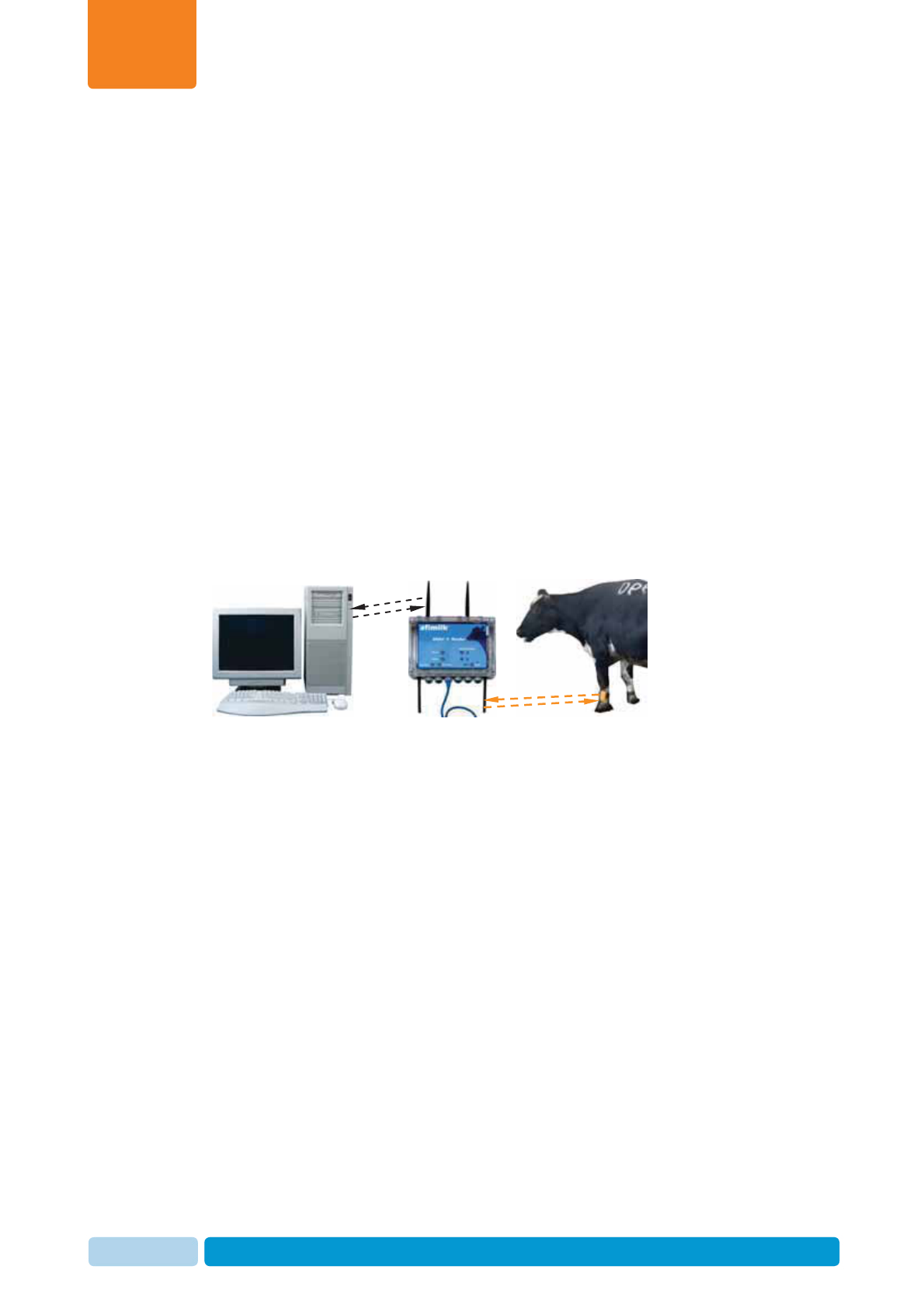
1.1 Principle of Operation
The following diagram shows the data flow in the AfiAct II system.
Figure 1: AfiAct II system data flow
AfiAct II uses Long Range (LR) communication to collect data from cow tags
(AfiTag II sensors) and transfers the information via a standard network (IP based
Wi-Fi or wired communication) to a PC based analysis.
Tags are placed on the cows’ legs. The AfiTag II holds the unique ID of each cow,
and records its number of steps, standing time, rest time and bout. The tags use LR
(Long Range) RF (Radio Frequency) communication to send this data periodically
(every pre-defined time-interval, default is 15 minutes) to an antenna located in the
lower part of the AfiAct II reader device (two antennas that provide optimal
coverage).
AfiAct II Reader collects data from the cows’ tags which are within its receiving
range. The Reader uses either wired or Wi-Fi communication to send the data to the
PC for analysis (2 upper antennas are for Wi-Fi, when used).
The AfiAct II software, located on the PC, uses the collected activity data of each
cow to calculate when the cow is in estrus and find the best time for breeding. The
application generates reports and alerts the farmer.
The communication used by the entire system complies with local regulations and
safety tests, corresponding with the ‘home appliance’ category.
Long Range (LR)
communication
Wired/Wi-Fi
communication
Introduction
Chapter
1
Oct 2013 AfiAct II™ Installation Manual2
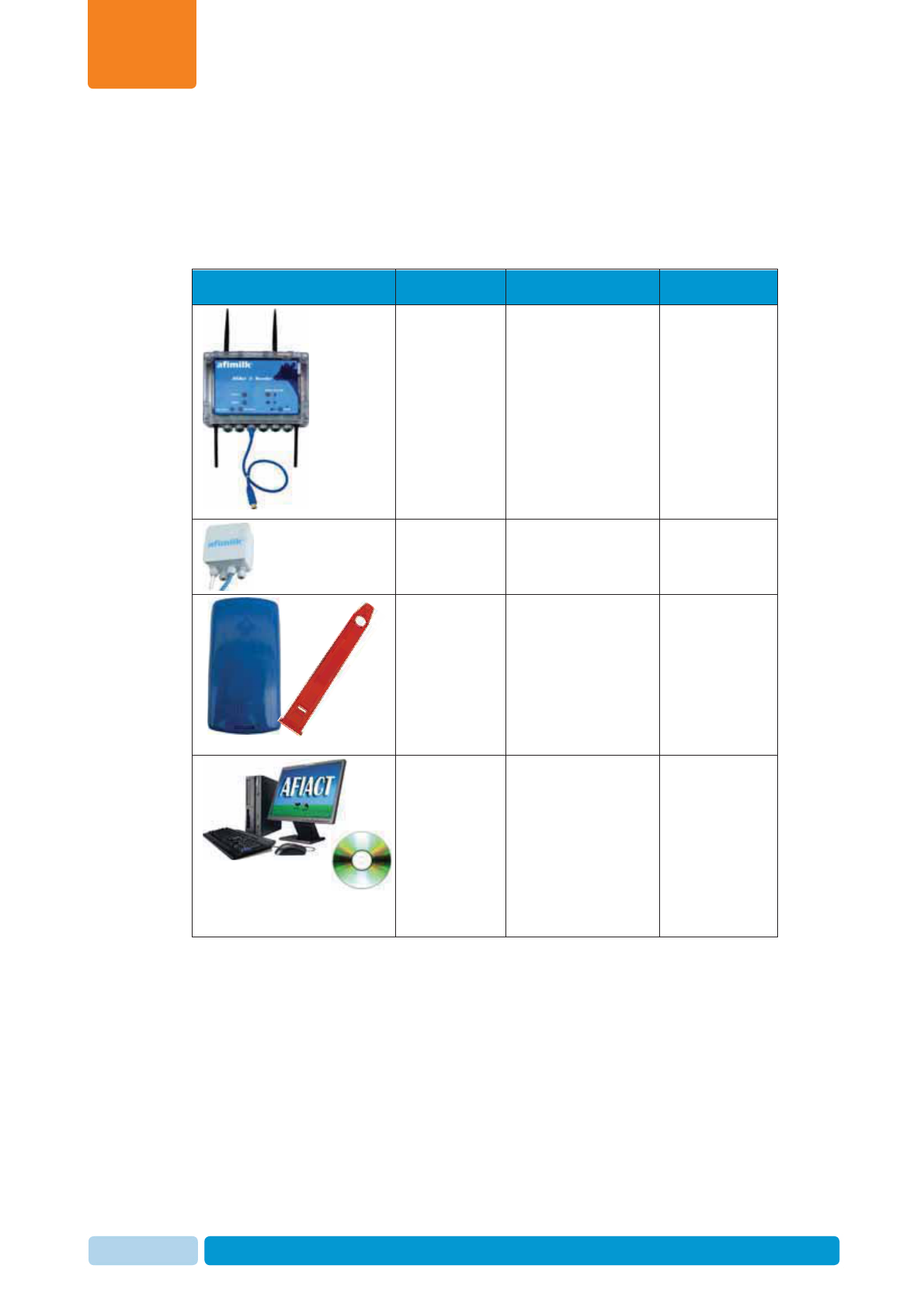
1.2 AfiAct II Components
The following table provides a list of the basic AfiAct II system elements. For
specific part numbers, refer to the detailed tables of each element.
Table 1-1. System Components
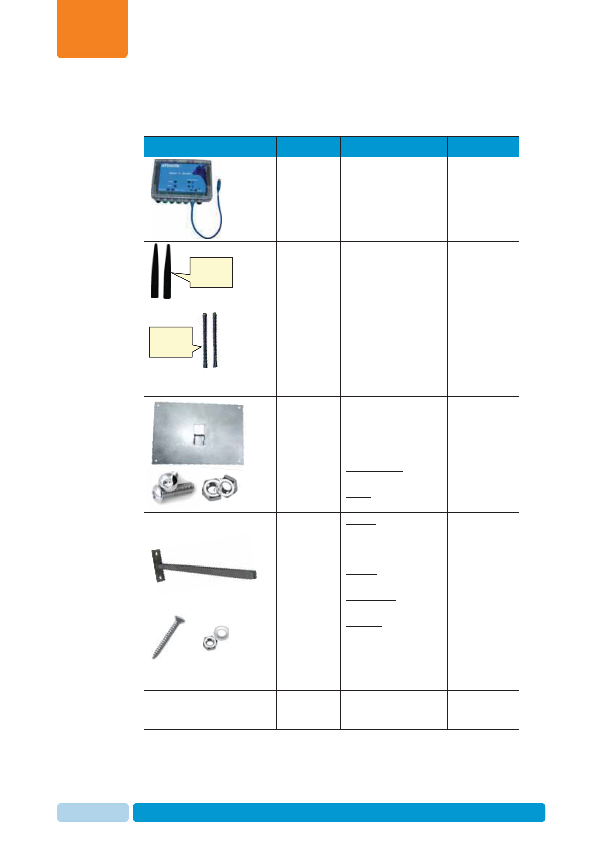
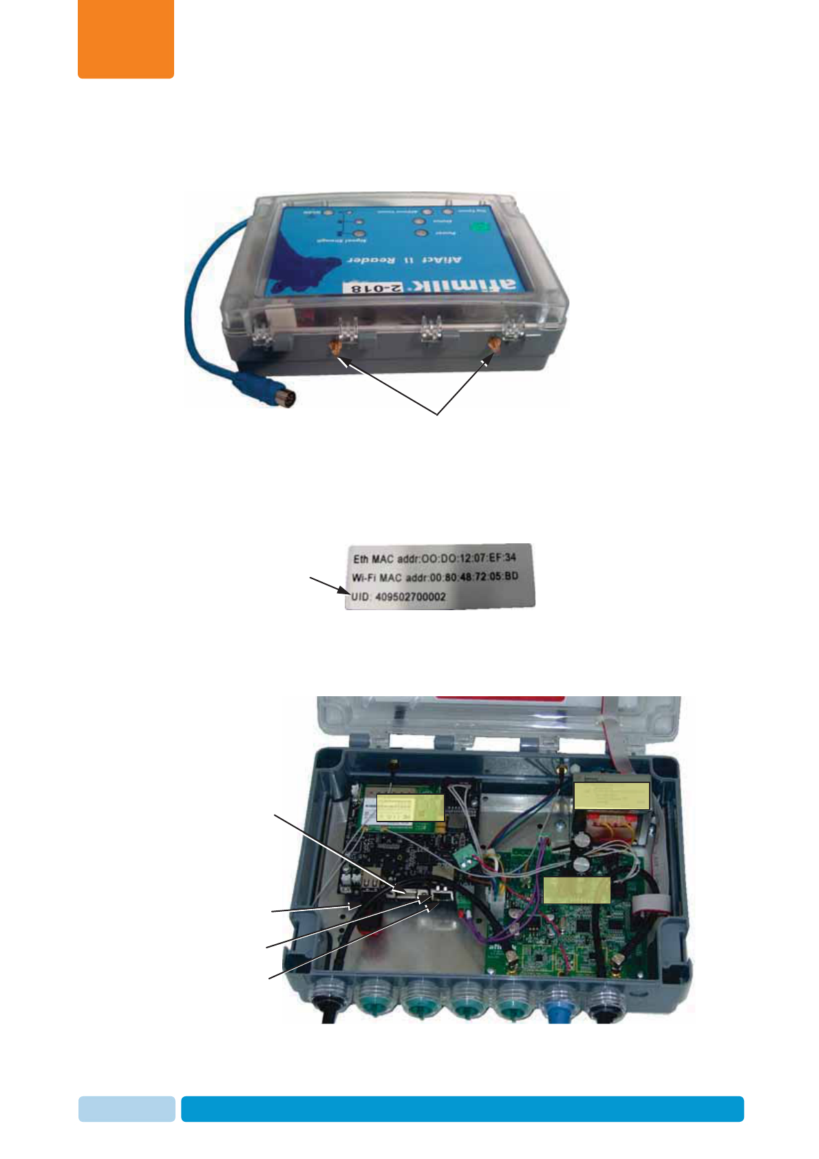
Picture Name Description PNs – see:
AfiAct II
Reader
(including
antennas and
brackets)
4256000
4256001
The Reader is the
interface between
the tags and the
AfiAct II Software.
Lower antennas are
for the Reader-tag
communication,
Upper antennas are
for the Reader-PC
Wi-Fi
communication.
1.2.1
Electrical
connection
box (4085851)
Electrical cable
connection box 1.2.2
AfiTag II
(4009600
4009610
4009620
4009630)
afimilk’s cow-tag,
including the
attachment strap.
A tag should be
attached to every
cow participating in
the AfiAct II group.
1.2.3
AfiAct II
software
program
(AfiFarm5 +
RT studio
module)
CD with PC
software to control
the system:
AfiFarm5 for user
interface;
RT System
module for data
collection from the
Reader.
4196000A2
Introduction
Chapter
1
Oct 2013 AfiAct II™ Installation Manual3
1.2.1 Reader Box Components
Table 1-2. Reader Box Components
Picture Name Description PN
AfiAct II
Reader AfiAct II Reader:
x916MHz final assy
x868MHz final assy
xDisplay Printed
Circuit Board
xTested PCB Assembly
4256000
4256001
Antennas 2 upper Wi-Fi Short
Range (SR) (pink)
antennas 2.4GHz
2 lower Long Range
(LR) ROD antennas
915MHz:
xYellow stripe for 916
MHz (e.g. USA,
Israel)
xGray stripe for 868
MHz (e.g. Europe)
xChina (TBD)
4025916
4025915
Bracket plate
connected to
Reader
Bracket plate
(for Reader-to-bracket
plate connection):
4 Allen screws
8 nuts
5002009
9020383 *4
9020212 *8
Bracket arm Bracket
to connect Reader to
bracket:
1 screw M8
1 Nylock nut
1 washer M8
(screws for wall
connection – not
supplied)
5231558
9020822
9020033
9020807
3m network
cable Not provided!
To be brought with
technician kit
9030498
Lower LR
antennas
Upper SR
antennas
Introduction
Chapter
1
Oct 2013 AfiAct II™ Installation Manual4
1.2.2 Electricity Box Components
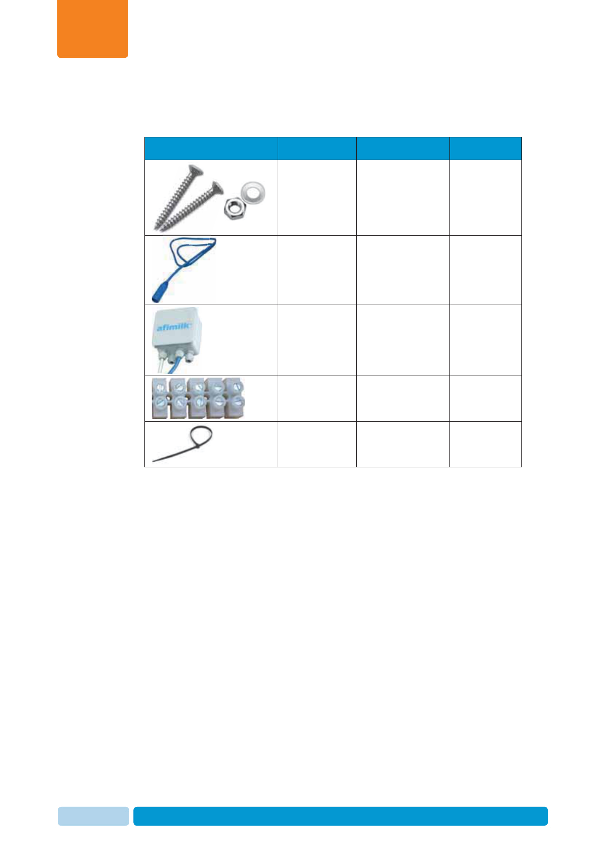
Table 1-3. Electricity Box Components
Picture Name Description PN
Screws and
nuts
Not provided!
To be brought with
technician kit.
Short (2.4m)
extension
power cable
Not provided!
Technician to check
and bring required
cable length.
4093506
Electrical
connection box
for AfiAct II
Reader
Not provided!
To be brought with
technician kit.
4085851
Electrical
terminal block
Not provided!
To be brought with
technician kit.
9020201
Cable ties
Not provided!
To be brought with
technician kit.

Introduction
Chapter
1
Oct 2013 AfiAct II™ Installation Manual5
1.2.3 Tag Types
Table 1-4. Tag Types
Picture Description PN
AfiTag II, Type A, 200 KHz SR,
916 MHz LR 4009600
AfiTag II, Type A, 200 KHz SR,
916 MHz LR, Israel 4009600i
AfiTag II, Type B, 80 KHz SR, 868
MHz LR 4009610
AfiTag II, Type E, 200 KHz SR,
Japan MHz LR 4009650
AfiTag II, Type F, 80 KHz SR, 868
MHz LR, Lemmer 4009660
Introduction
Chapter
1
Oct 2013 AfiAct II™ Installation Manual6
1.3 AfiAct II Reader – Indicators and I/Os
The following sections describe the Reader’s indication LEDs, input and outputs.
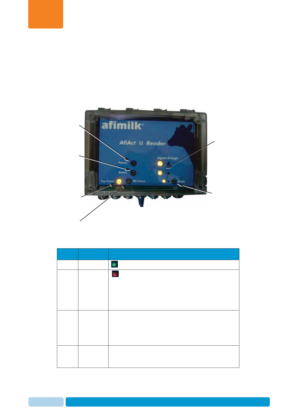
1.3.1 Front Panel - LED Indications
The following image shows the Reader’s fault and indication LEDs.
Table 1-5. External LED Indications
Item LED Label Description
1 Power – ON
2 Status - LED is steady ON – Indicates that the reader is in
internal communication fault mode.
LED is blinking RED – Indicates that there was no tag
message for twice the Transmit (Tx) interval, i.e.: if the
time is (default) 15 minutes, the LED will blink if there
was no tag message for 30 minutes.
3 Tag Comm Communication with tags:
Blinking Yellow – good communication
Off – No communication
Note: This LED blinks for a short period every time a tag
message is received in the Reader.
4 PC comm Communication with the PC AfiAct II application
Yellow – The Reader is communicating with the AfiAct II
Off – Reader could not connect with AfiAct II
1. Power ON
3. Tag
communication
available/not
available LED
2. Status
6. Wi-Fi signal
strength indication
5. WLAN LED:
Relevant only if the
Reader is associated
to a Wi-Fi Access
Point, indicating that
a association
between the Reader
and AP has been
established
4. Indication o
f
communication
with AfiAct II
application
Introduction
Chapter
1
Oct 2013 AfiAct II™ Installation Manual7
Item LED Label Description
5 WLAN
This LED is relevant if the Reader is associated with a
Wi-Fi Access Point, and indicates if an association
between the Reader and AP has been established. If it is
ON, check the connection quality via the Signal
Strength LEDs
6Signal
strength Indicates Wi-Fi communication strength, after the WLAN
LED shows successful association between the Reader
and the AP.
Note: When no strength LEDs are on and the WLAN LED
is on, the signal strength is below -90
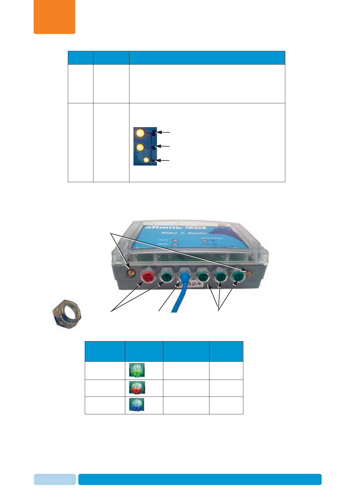
1.3.2 Lower Panel – Inputs and Outputs
The following image shows the Reader’s lower panel inputs and outputs.
Table 5-6. Grommets
Cable Type Grommet
Color Diameter PN
Antenna
green
6.5 mm (¼”) 5001764
Communication
red
5.0 mm (3/16”) 5001762
Power
blue
7.0 mm (¼”) 5001763
Good signal strength (> -60 dbm)
Medium signal strength (between -60
and -80 dbm)
Low signal strength (between -80 and
-90 dbm
)
Tag LR antenna
connectors
Grommets Input power
cable Grommets
Grommet Nut
Introduction
Chapter
1
Oct 2013 AfiAct II™ Installation Manual8
1.3.3 Upper Panel – Inputs and Outputs
The following image shows the Reader’s upper panel inputs and outputs.
1.3.4 Side Panel with Attributes Label
On one of the Reader’s side panels you will find the following label, indicating the
Reader’s attributes
1.3.5 Reader Box – Inputs and Outputs
The following image shows the Reader’s inner inputs and outputs.
Network cable
connector
Not to be touched
(USB drive
connector
)
Serial connection
(generally: not to
be touched
)
Wi-Fi antenna
connectors
Main Board
afimilk LR
Power supply
Reader’s Unique ID
(UID)
Introduction
Chapter
1
Oct 2013 AfiAct II™ Installation Manual9
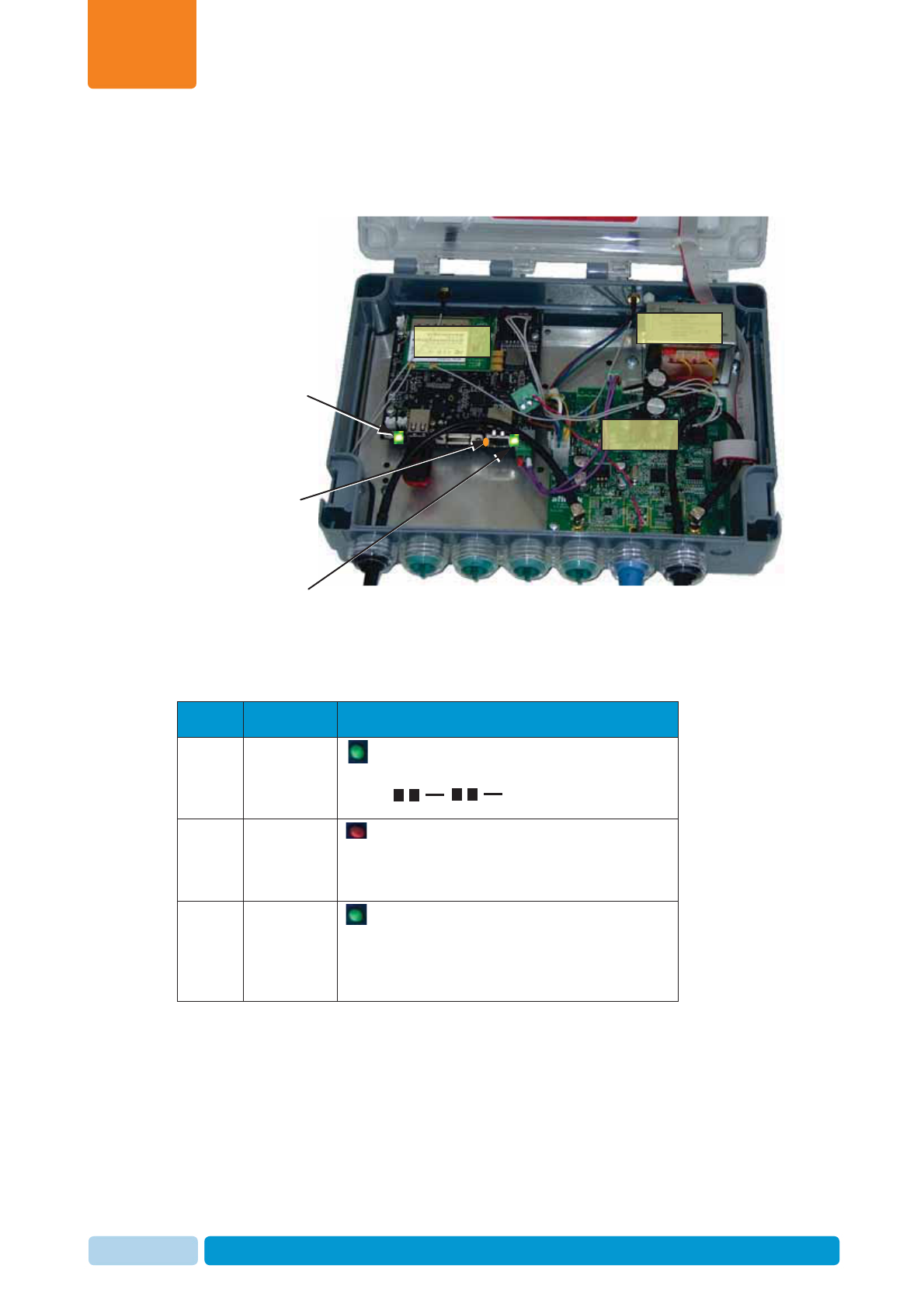
1.3.6 Reader Box – Internal LEDs
The following image shows the Reader’s inner inputs and outputs.
Table 1-7. Internal LED Indications
Item LED Label Description
1Host Board
operating
system
indication
– Host-Board Operating System completed
loading and is active (blinks: two short and
stop).
2Physical
network
cable
connection
- Orange LED that indicates physical link.
3Network
cable
connection
with data
flow
- Green LED which blinks when data
flowing over the Ethernet line
.
2. Orange LED:
Network cable
connector
verification
1. Green LED:
Host-Board OS
active LED
3. Green LED:
network packet
flow indication
Main Board
afimilk LR
Power supply
Introduction
Chapter
1
Oct 2013 AfiAct II™ Installation Manual10
1.4 AfiAct II Reader Power Specifications
The AfiAct II Reader power connection must comply with the following
specifications:
Table 1-8. Power Specifications
Item LED Label
Voltage Nominal voltage of 24Vac (minimum 21.6Vac to maximum
27.5Vac)
Current 0.6Aac
Power per
unit 16.5 Watts (i.e. a VA rating of at least 20 VA for the
transformer)
Number of
Readers
powered by
a single
transformer
The standard afimilk 24Vac, 75VA rated transformer can
power up to 3 Reader units, considering the cable length
and diameter, see following note.
NOTE
A corresponding transformer box may be ordered separately from afimilk; PN
4096130 (not for USA).
NOTE
To avoid unacceptable electrical power reduction, the cable length and
diameter must be validated, too ensure the cable is not too long per its
diameter.
Introduction
Chapter
1
Oct 2013 AfiAct II™ Installation Manual11
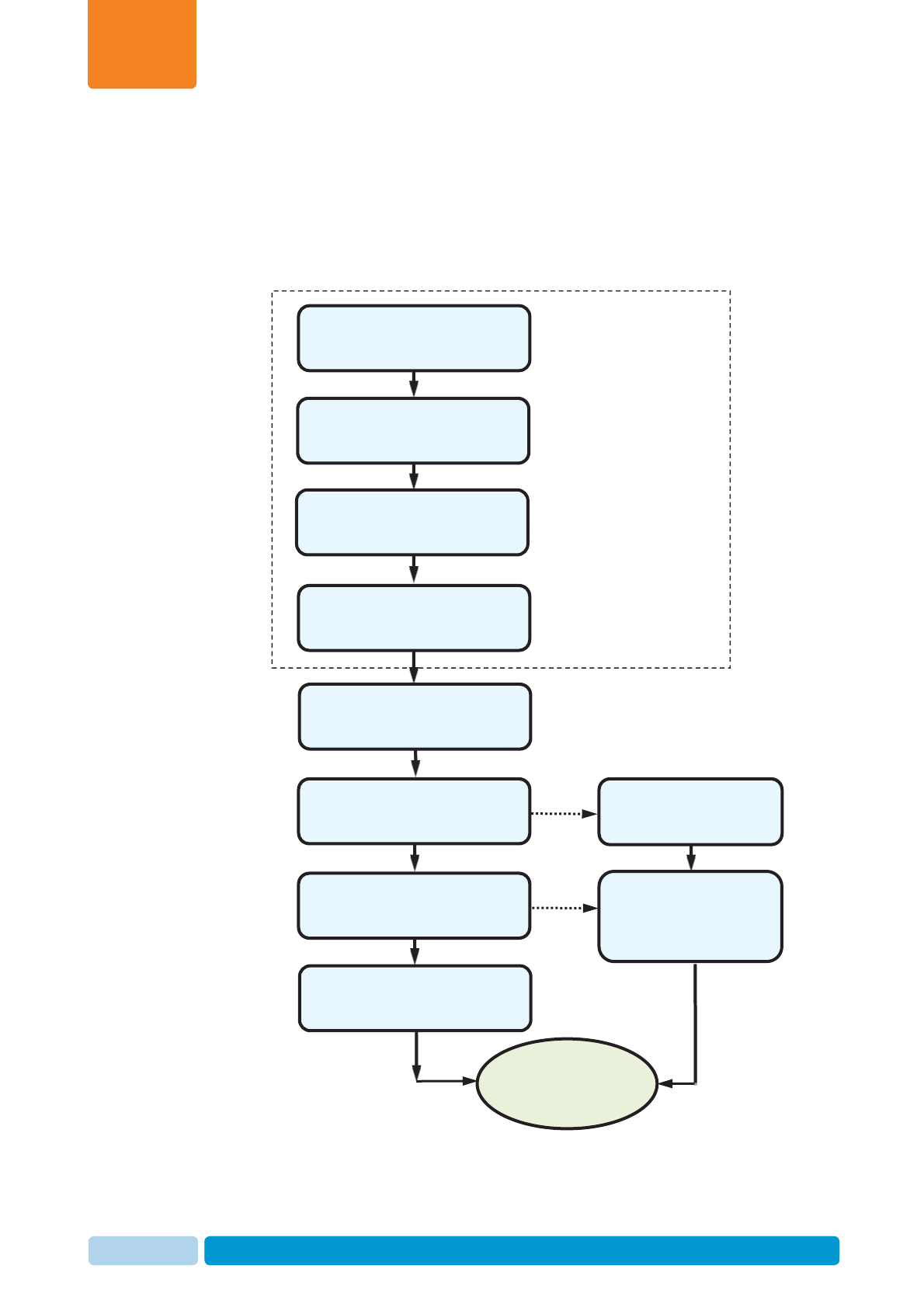
1.5 System Installation Overview
To fully install AfiAct II system, pre-installation preparation is needed; some
preparations are done by Dealers’ technicians, and others are the farmer’s
responsibility. The following flowchart presents the preparation and installation
phases and the responsible party per phase.
Plan &
prepare
site
Set network coverage (wired
/ Wi-Fi), see 2.2
Determine AfiFarm
deployment needs, see 2.3
Attach tags to cows,
see 7
Install and set AfiAct II
software, see 4
AfiAct II Reader initial
communication, see 5
Mount the Reader in the
cowshed, see 6
Prepare PC prerequisites,
see 2.4
Farmer: provides shed scheme
Dealer: defines mounting points
Farmer: set and check coverage
in locations determined by the
dealer
Farmer: Prepare AfiAct II
software PC pre-requisites
Farmer
System is
installed
Dealer&farmer: AfiFarm
deployment (standalone/existing
AfiFarm + version)
Enter cow data into
system (done by the
farmer), see 8
In parallel
In parallel
Dealer
Dealer
Dealer
Farmer
Assemble the Reader, see 3
Determine reader mounting
point, see 2.1
Prerequisites and Site Planning
Chapter
2
Oct 2013 AfiAct II™ Installation Manual12
2 Prerequisites and Site Planning
Before starting AfiAct II installation, verify that all pre-requisites are fulfilled:
1. Reader mounting point: Identify a proper location for AfiAct II Reader, see 2.1
2. Verify network coverage in the required area, see 2.2
Note: It is highly recommended that the network technician be present
during the Reader installation.
3. Verify existing AfiFarm version and system deployment (this is relevant for
farms using both systems), see 2.3
4. Validate AfiAct II PC corresponds with the requirements, see 2.4
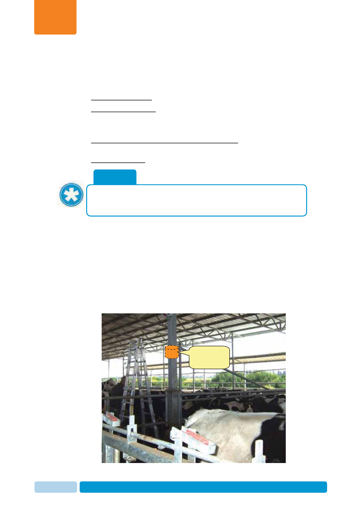
2.1 Determine Reader Mounting Location
Determining optional Reader mounting points is done by the Dealer technicians. To
do this, either get a scheme of the shed dimensions from the farmer (including
poles, electricity outlets, distance from the office, etc.), OR visit the farm before the
installation to perform a site survey.
The farmer receives from the dealer a list/scheme showing the optional mounting
points, and the required coverage radius. It is the farmer’s responsibility to provide
coverage in these points.
NOTE
To determine the system sampling sessions during the installation,
investigate the specific site needs. This can be performed during the
preparations phase, or during the installation, see 4.3.2.
Optional reader
positioning
location
Prerequisites and Site Planning
Chapter
2
Oct 2013 AfiAct II™ Installation Manual13
The Reader mounting location is based on the cowshed size and location, and
should comply with the following conditions:
xHeight: The Reader is mounted on a pole about 3.5 meters high from the
ground.
xCoverage (tags and Wi-Fi/wire): (fine-tuning will be performed while mounting)
x The mounting pole location must allow tag-coverage range for the whole
defined area. This is determined according to the shed scheme, and will
probably be around the center of the required 80 meters coverage radius,
also covering the feeding and water trough areas.
x The Reader should have a line of sight towards cow tags, with minimal
interference from other sheds/poles/buildings, etc.
x The Reader should have WiFi / Wired connectivity to the Access Point /
office.
xPower access: The pole has near access to a power outlet (to be provided by
the farmer).
xAccessibility: The Reader and power box can be easily viewed and accessed
for maintenance (if possible – accessible from the passage).
xWeather protection: The Reader and power box must be located under a roof
with minimal exposure to weather conditions, according to the following
specifications:
x The structure may be made of metal or wood.
x The roof should be at least 4 meters high and may be made of a plastic
material (but not aluminum or sheet metal).
x The roof must be large enough to prevent any direct sun or rain exposure to
the device.
x If the sides are closed, this siding material should not be metal either.
x If metal fencing is used to keep animals out, it should be a large opening
Australian-type fencing material (at least 30 cm) (otherwise the
communication signals may be reduced).
NOTE
The final coverage and corresponding location determination must be done
during a site survey and could vary according to specific farm environment.
Prerequisites and Site Planning
Chapter
2
Oct 2013 AfiAct II™ Installation Manual14
2.2 Setting up Network and Power Coverage
The customer may determine the type of network communication used between the
PC and the Reader; either wired or Wi-Fi can be used. However, it is the customer’s
responsibility to ensure power point and network coverage in the office and in the
Reader-determined mounting point (in the cowshed – according to the Dealer’s
technicians). In either case, the office and Reader network coverage setup must be
completed and tested before starting the Reader installation (e.g. via a laptop
computer, smartphone, or in future releases, via tag-indicator).
Note: The Wi-Fi network must in turn provide an IP to the Reader’s MAC address.
Office Wi-Fi Coverage
The office Wi-Fi coverage is a recommendation, and it is required when configuring
the Reader to work with the AfiAct II software.
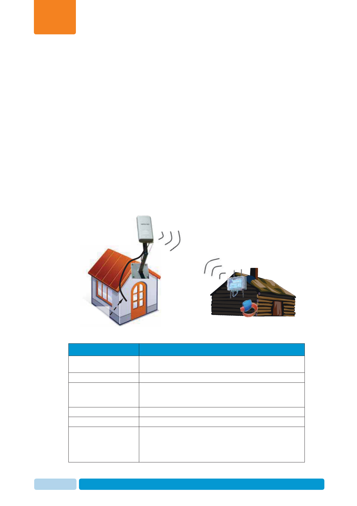
PC to Reader Wi-Fi coverage
The Reader’s network coverage is set after determining the Reader installation point
in the cowshed. The following figure shows an example of network coverage in the
office and cowshed.
Wi-Fi Specifications
Item Value
Network Any commercial access point
Carrier grade (99.999% service).
WiFi certification supports 802.11g or 802.11n
Encryption method default WPA-PSK/WPA2-PSK
The following methods are also supported:
WEP, WPA/WPA2, WPA-PSK/WPA2-PSK and IEEE 802.1X standard
Preferable SSID afiact2
Preferable password afimilk123
Signal and Noise xThe SNR at Reader mounting point must be greater than 15 dB.
xRSSI must be higher than -80dBm.
Note: Preferred RSSI is -65 dBm to -55 dBm in the designated
Reader mounting point
Wi-Fi coverage towards
cowshed reader
Wired connection
towards office Wi-Fi
t
Wi-Fi
Access Point

Prerequisites and Site Planning
Chapter
2
Oct 2013 AfiAct II™ Installation Manual15
2.3 Determining the Deployment Type
The deployment may be either as a standalone system or as an integrated-mode-
with-AfiFarm system, where AfiAct II is automatically synchronized with the existing
AfiFarm system.
For integrated mode with AfiFarm systems, verify that the AfiFarm version is 4.0.1 or
higher.
To check your AfiFarm version number
1. Open your AfiFarm application: double-click on the AfiFarm icon . The
AfiFarm window opens.
2. Click Help in the upper tool bar and select
About AfiFarm from the roll-down menu. The installed version number will be
displayed.
If your AfiFarm version is lower than 4.0.1 – upgrade your AfiFarm version. Refer to
AfiFarm4 Installation manual, see referred documents on page vii.
Prerequisites and Site Planning
Chapter
2
Oct 2013 AfiAct II™ Installation Manual16
2.4 Prepare the PC Environment
Before starting to install AfiAct II software, verify that your PC corresponds to the
following set of requirements:
x The computer uses a supported operating system, see 2.4.1
xMemory & processor requirements, see 2.4.2
xNetwork connections comply with the requirements, see 2.4.3
xAdditional Windows 7 preparations, see 2.4.4
xVerify the PC is prepared, see 2.4.5
These requirements are detailed in the following sections.
NOTE
It is highly recommended to have an internet connection, to allow efficient
support when needed.
NOTE
Verifying that you are using correct computer settings is essential for
performing the installation correctly, allowing correct operation of AfiFarm5. In
systems where there is a network administrator, he or she must be present
during the installation.
Prerequisites and Site Planning
Chapter
2
Oct 2013 AfiAct II™ Installation Manual17
2.4.1 Verify Operating System Compatibility
AfiFarm5 supports the following operating systems:
MS Windows7 - Professional/Enterprise/Ultimate 64 bit.
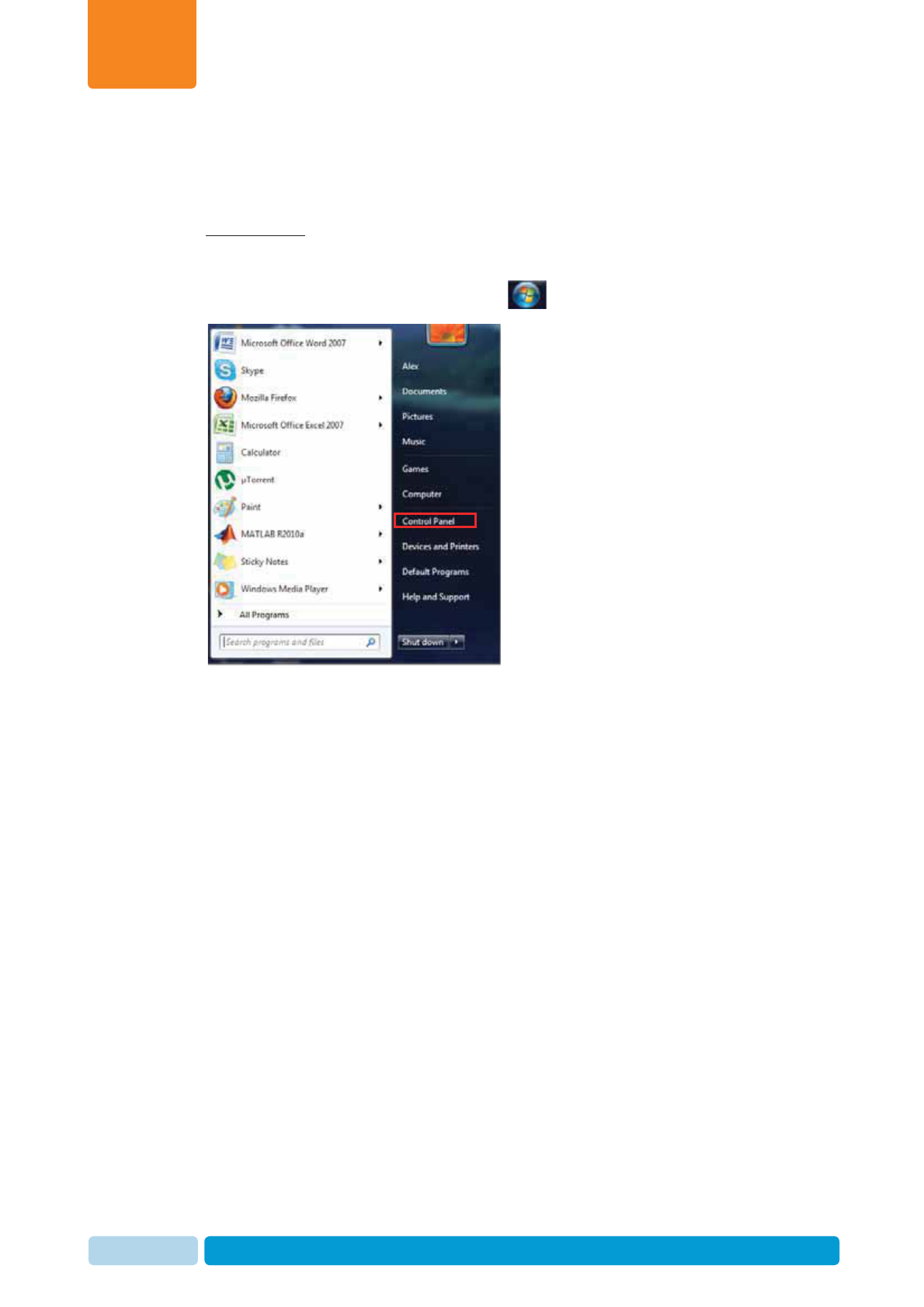
To verify your PC’s operating system compatibility:
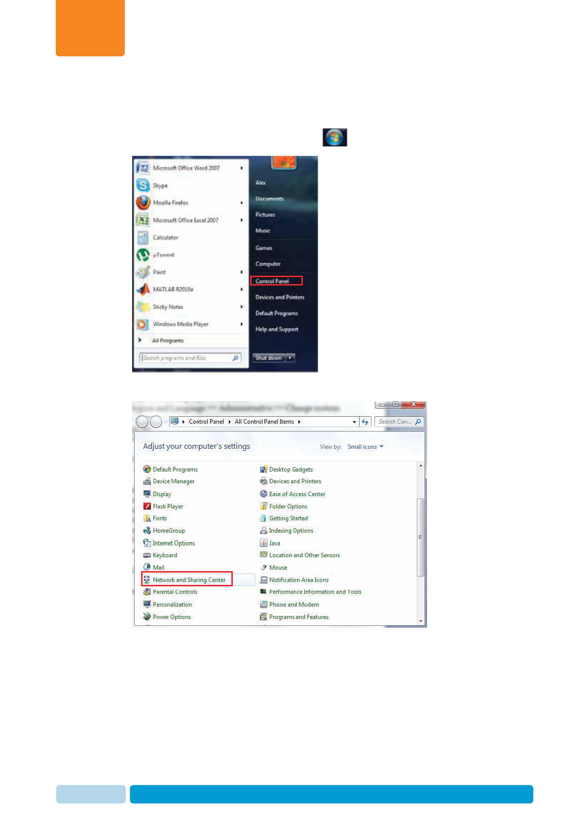
1. In your system tray, click the Start icon , and select Control Panel
Prerequisites and Site Planning
Chapter
2
Oct 2013 AfiAct II™ Installation Manual18
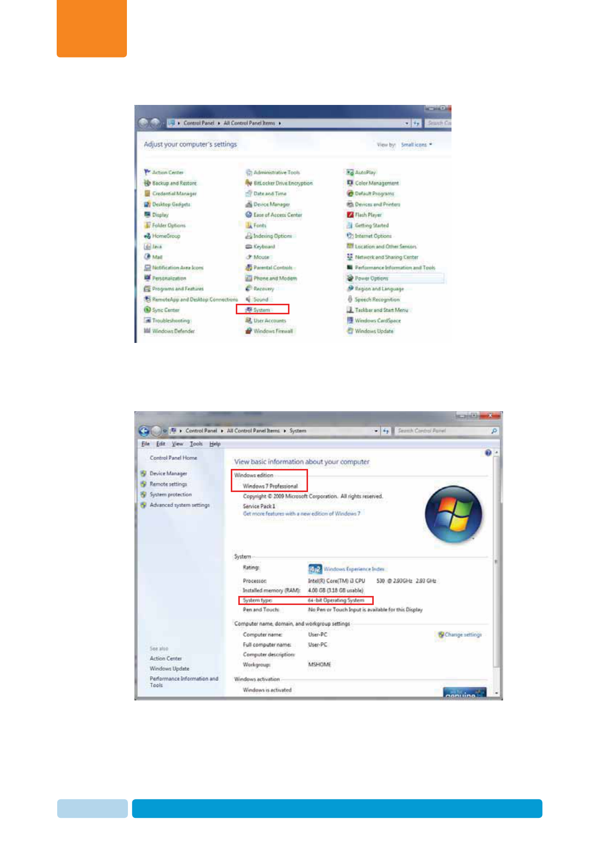
2. Click System.
3. Verify the following attributes:
xWindows edition: Windows 7 Professional/Enterprise/Ultimate
xSystem type: 64 bit.

Prerequisites and Site Planning
Chapter
2
Oct 2013 AfiAct II™ Installation Manual19
2.4.2 Memory & Processor Requirements
The PC minimum requirements are as follows:
x Operating system: Windows7 PRO 64-bit
x RAM: 4GB and above
x Processor: Core 2 Dual
x HD free space: 100 GB
x UPS unit – type is to be discussed with the PC supplier
x USB Flash drive of 8 GB or other backup device
2.4.2.1 Verify RAM and Processor
To verify required RAM and Processor:
1. In your system tray, click the Start icon , and select Control Panel
Prerequisites and Site Planning
Chapter
2
Oct 2013 AfiAct II™ Installation Manual20
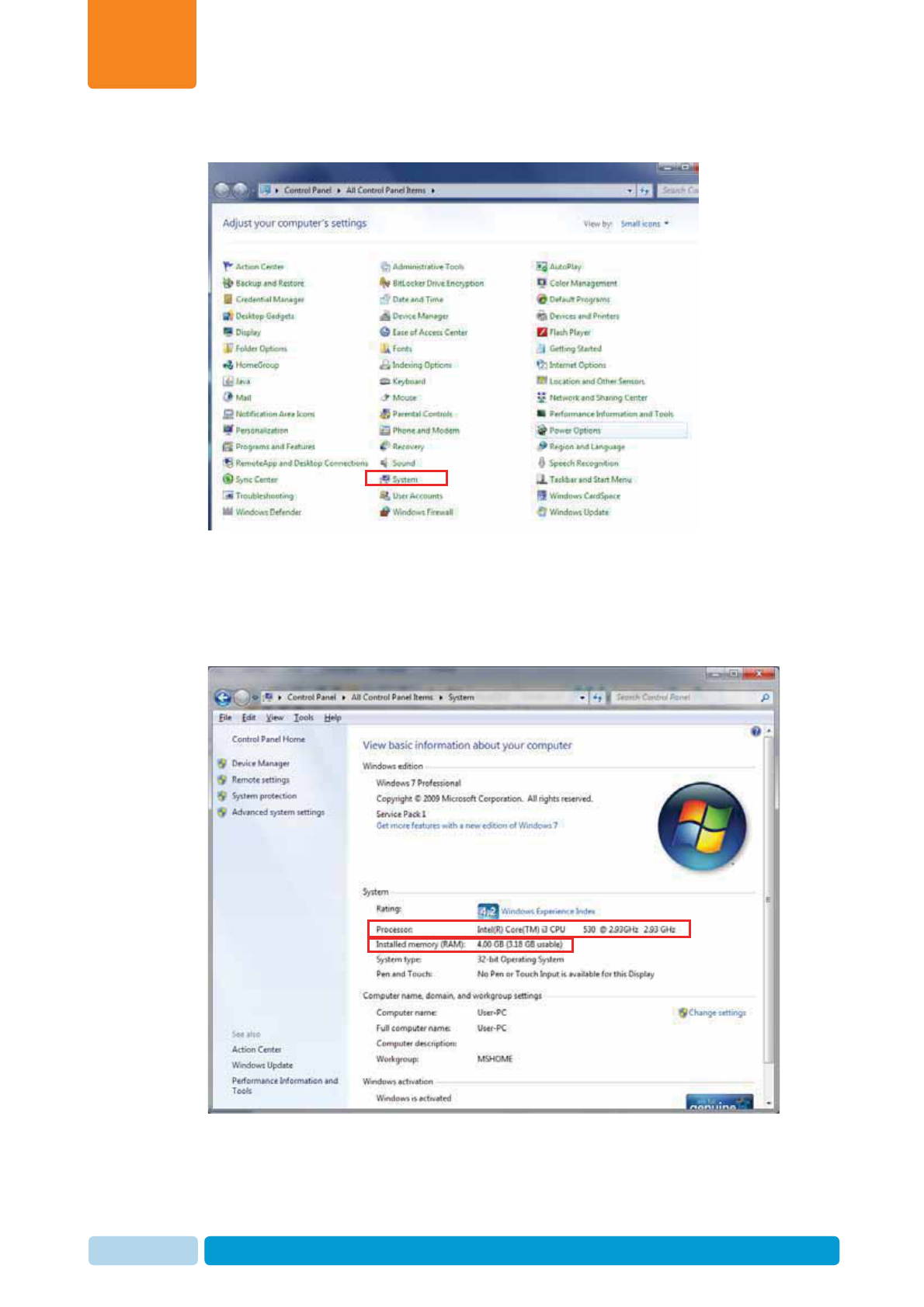
2. Click System.
3. Verify the following attributes:
xProcessor: Windows 7 PRO/Enterprise/Ultimate
xSystem Type: 64 bit
xRAM: 4GB and above.
Prerequisites and Site Planning
Chapter
2
Oct 2013 AfiAct II™ Installation Manual21
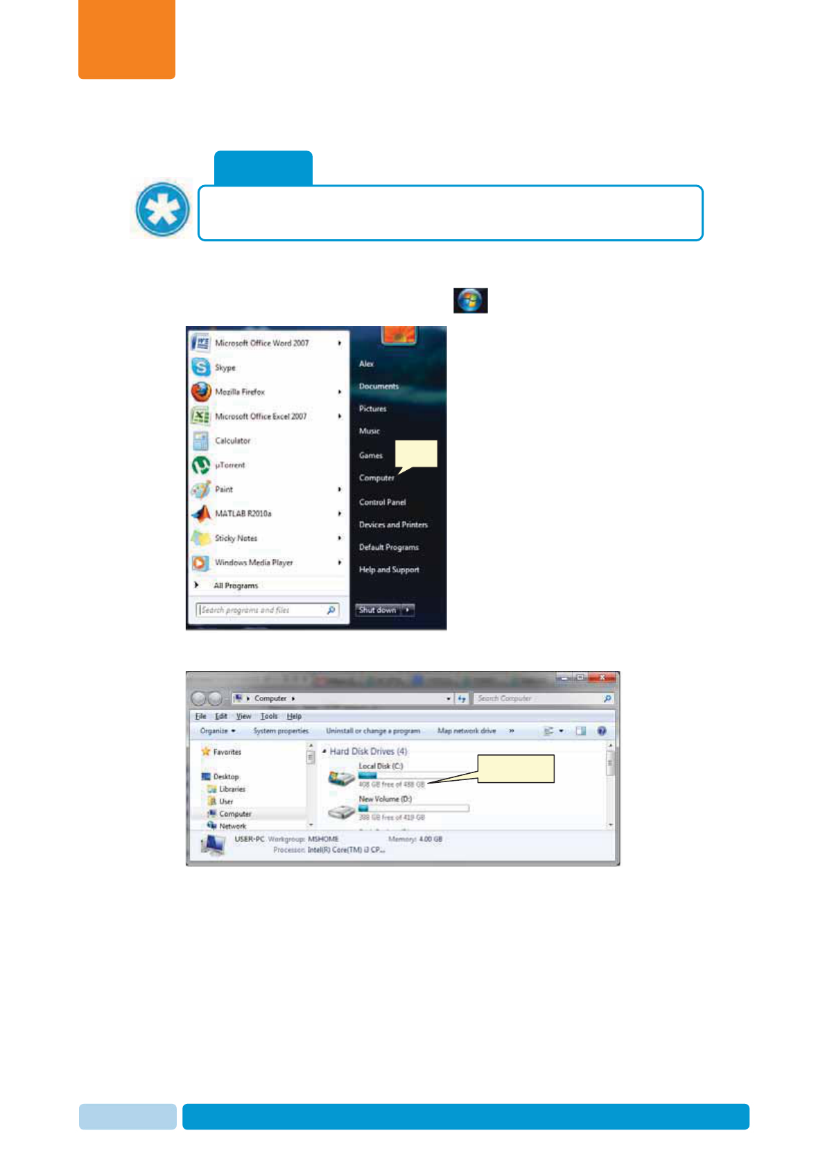
2.4.2.2 Verify HD Free Space and Type
To check your HD free space
1. In your system tray, click the Start icon , and Double-click on computer
2. Check free space on your hard drive.
NOTE
If the installation is done in a folder that is not the installation folder – verify
that there is enough disk space in BOTH disks.
Click
Free space

Prerequisites and Site Planning
Chapter
2
Oct 2013 AfiAct II™ Installation Manual22
2.4.3 Network Connections
AfiFarm5 Network connections must comply with the following conditions:
x The network is supported by Windows.
x The network supports TCP/IP.
x The network must be transparent for a UDP broadcast.
x The LAN must have a minimum speed of 100 MBps.
NOTE
In order to print reports, the system must have a printer, connected either
directly to the PC or via the network.
Prerequisites and Site Planning
Chapter
2
Oct 2013 AfiAct II™ Installation Manual23
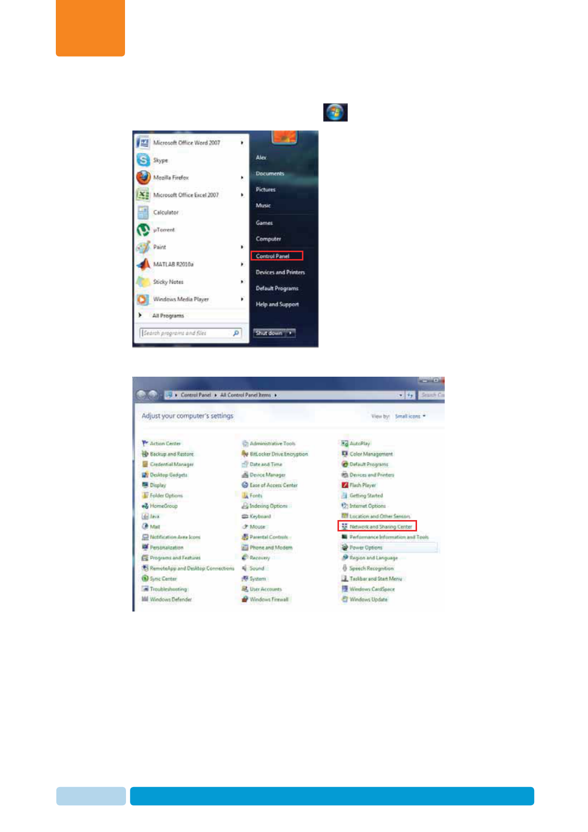
To verify your system has correct network connections
1. In your system tray, click the Start icon , and select Control Panel
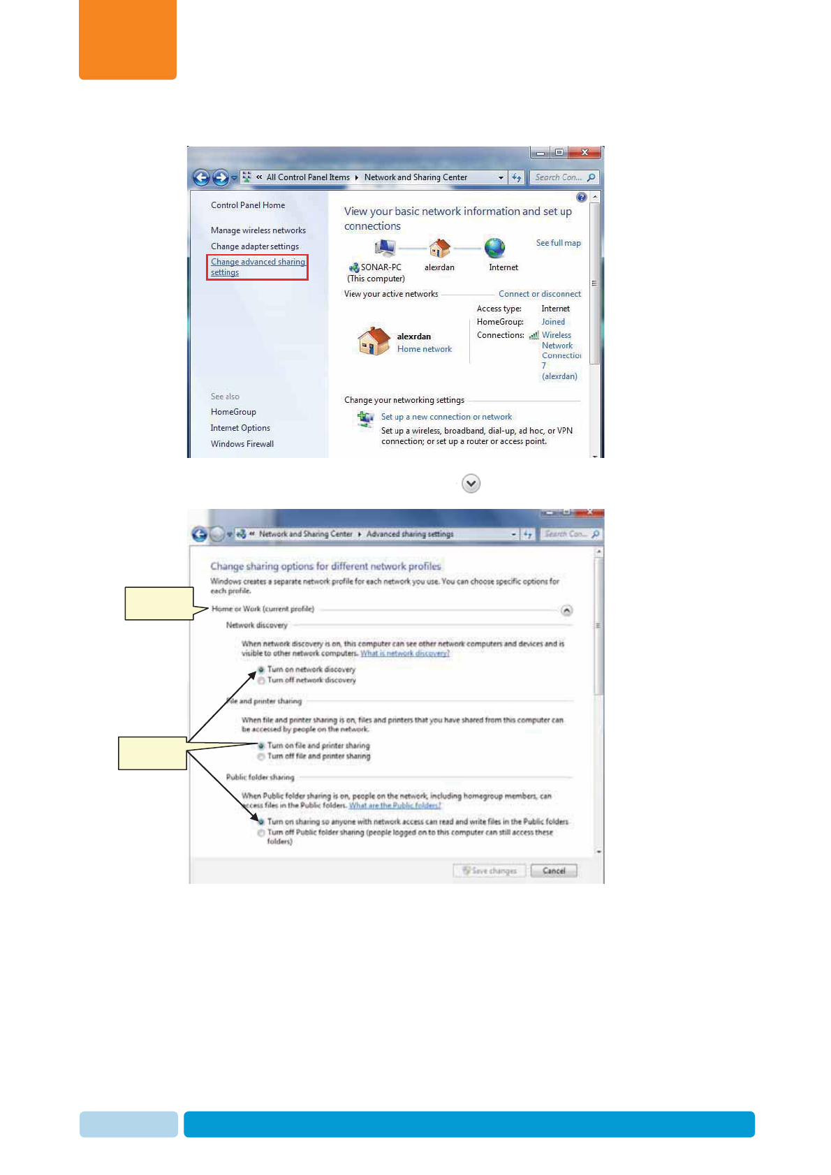
2. Click Network and Sharing Center.
Prerequisites and Site Planning
Chapter
2
Oct 2013 AfiAct II™ Installation Manual24
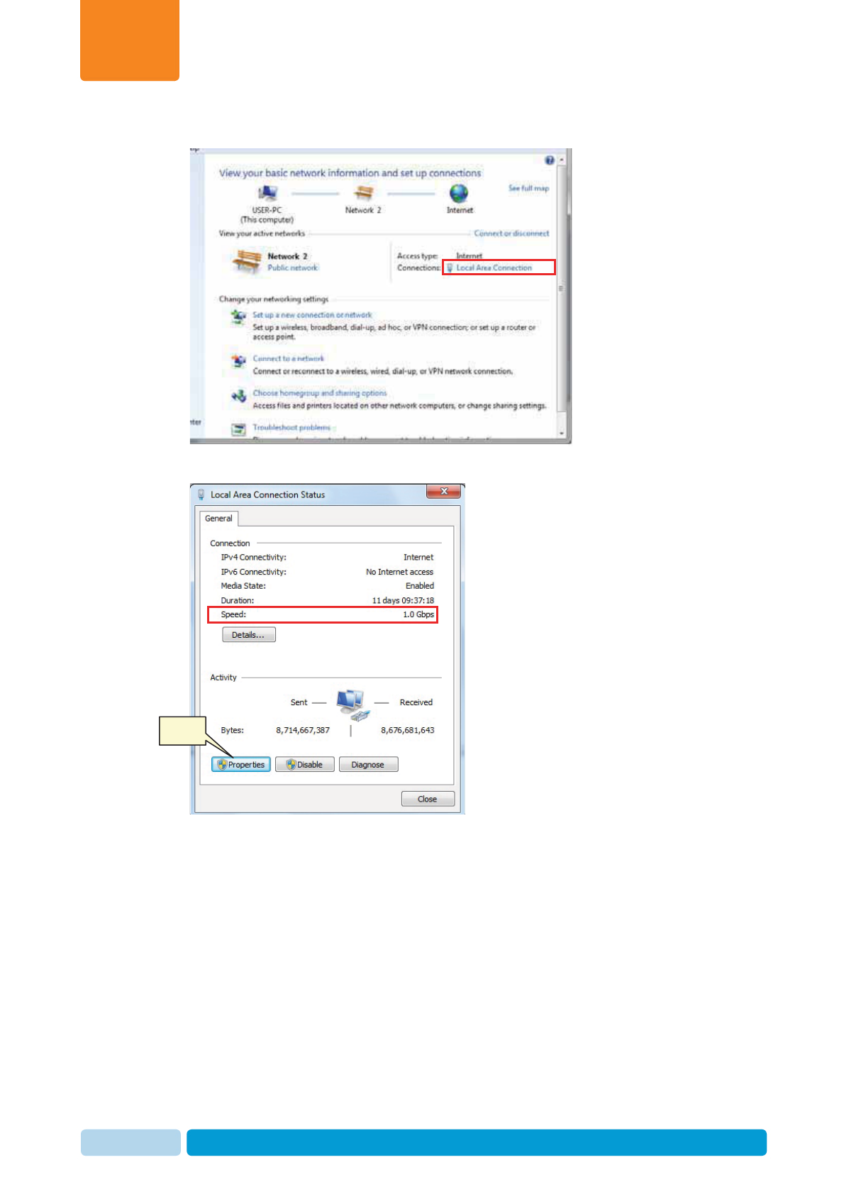
3. Click Local Area Connection
4. Verify that the Speed is 100Mbps or higher.
Click
Prerequisites and Site Planning
Chapter
2
Oct 2013 AfiAct II™ Installation Manual25
5. Click Properties.
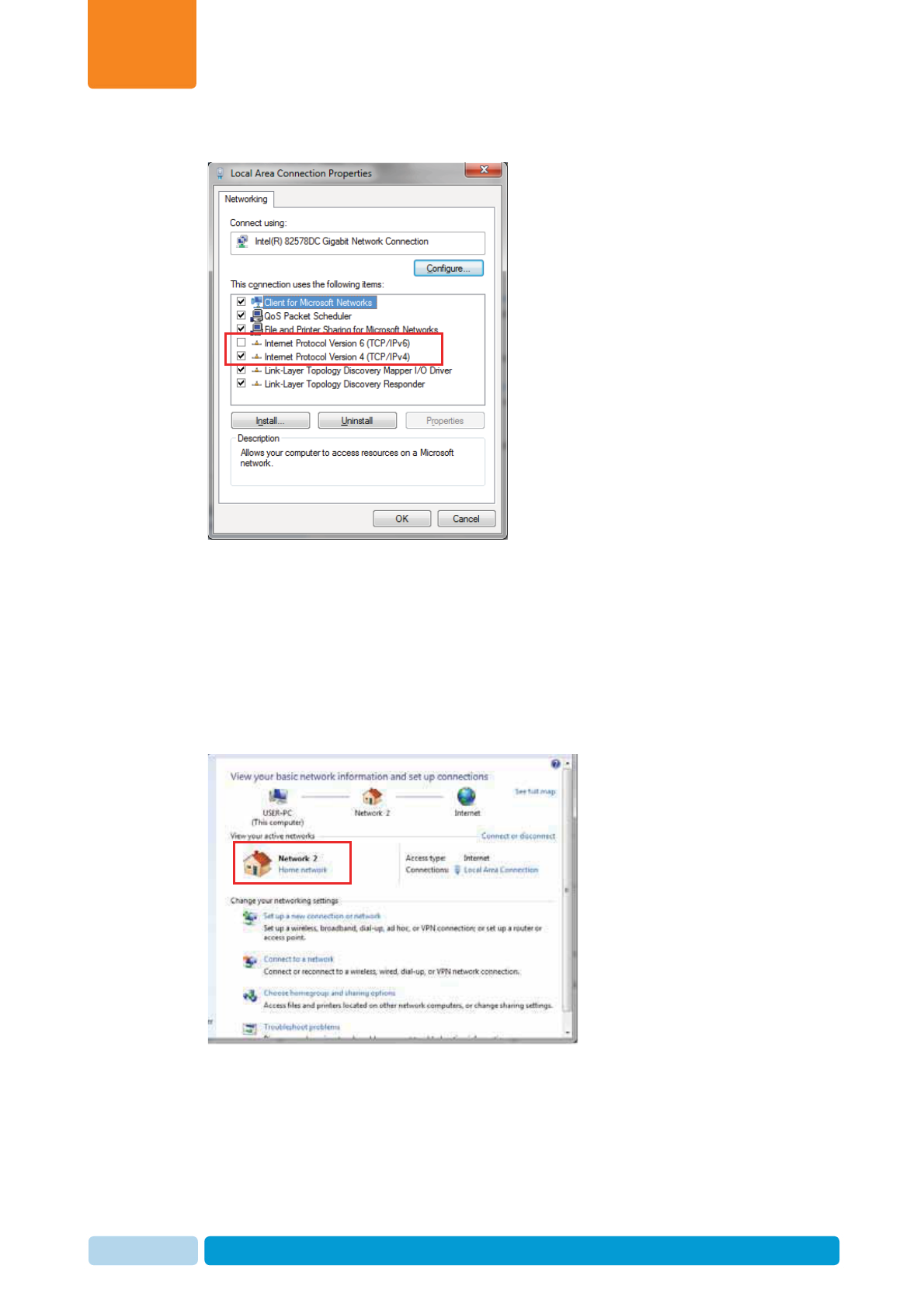
6. Click the Networking tab and check the following attribute is checked:
x Internet Protocol version 4 (TCP/IPv4)
Ensure the following attribute is unchecked:
x Internet Protocol version 6 (TCP/IPv6)
7. Click the OK, and then click Close.
8. In the Network and Sharing Center dialog, verify that the Network is set to
Home
Prerequisites and Site Planning
Chapter
2
Oct 2013 AfiAct II™ Installation Manual26
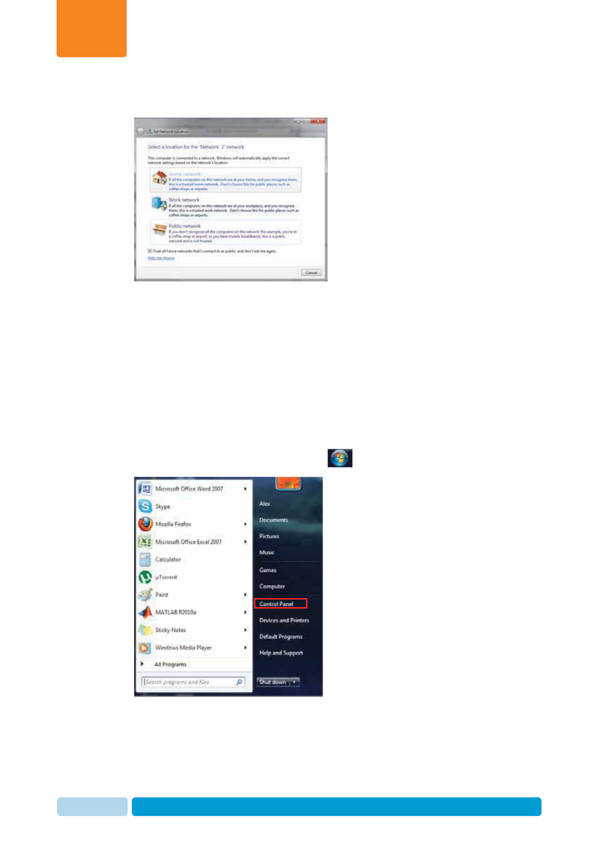
9. If the Network is not set to Home, click on the network value. The Set Network
Location dialog appears.
10. Choose Home Network and close the dialog.
2.4.4 Additional Windows7 Preparations
2.4.4.1 Verify using Administrator Account
AfiFarm operates on an administrator account. It must be installed on the same
administrator account under which it is expected to work. Changes in Windows
settings, and in AfiFarm installation, must be done from an Administrator account of
the computer.
To verify you logged-in using an administrator account
1. In your system tray, click the Start icon , and select Control Panel
Prerequisites and Site Planning
Chapter
2
Oct 2013 AfiAct II™ Installation Manual27
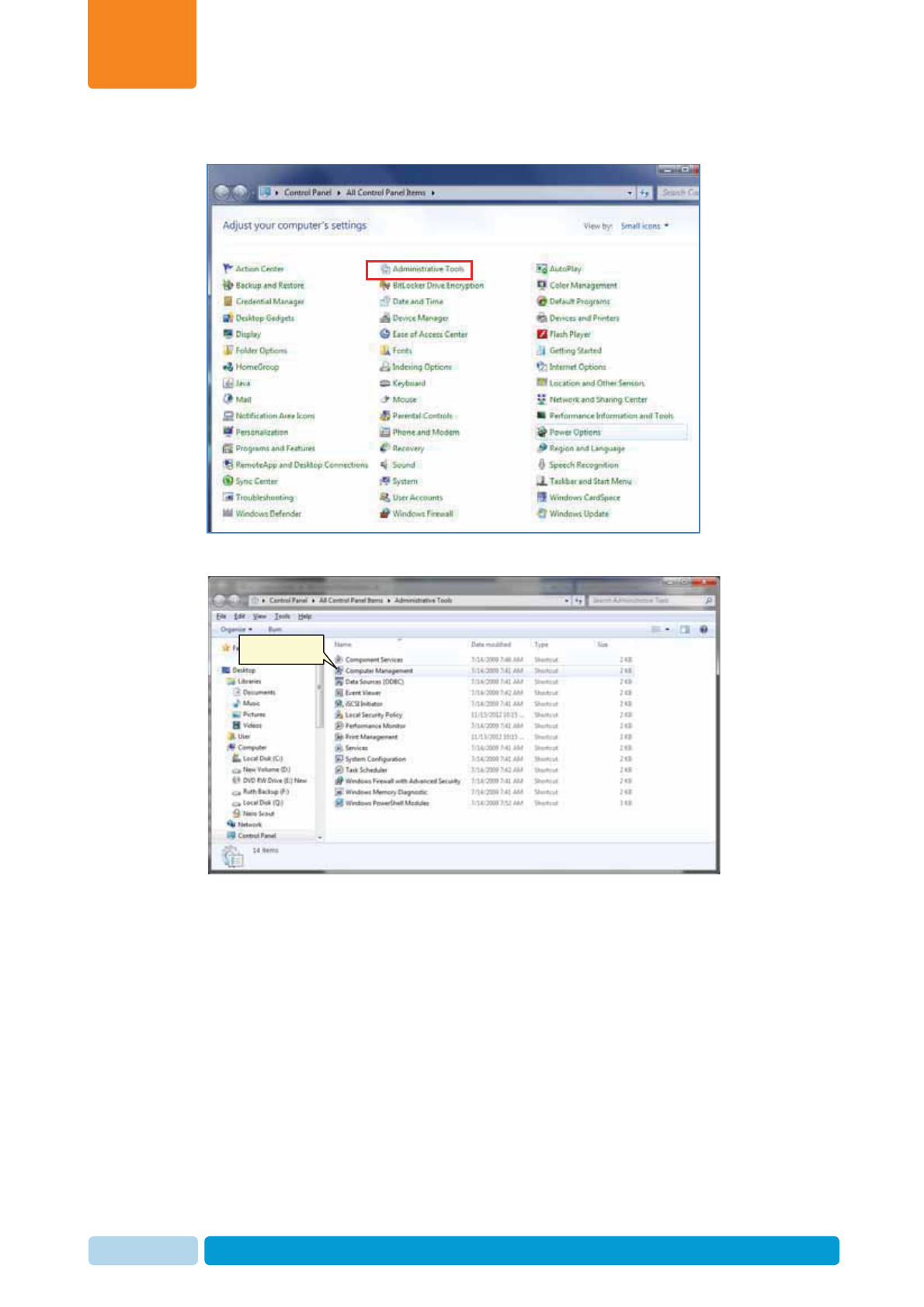
2. Click Administrative Tools.
3. Double click on Computer Management
Double-click
Prerequisites and Site Planning
Chapter
2
Oct 2013 AfiAct II™ Installation Manual28
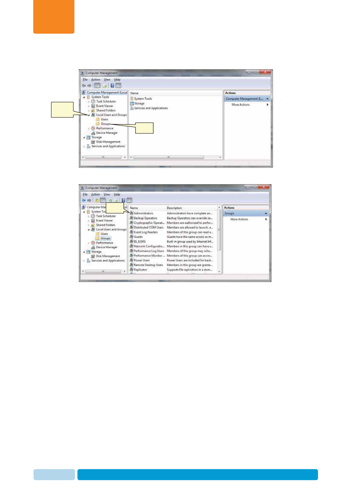
4. In the left pane of the computer management window, expand Local users
and groups, then double-click the Groups folder.
5. In the list of users, double-click Administrators
Click to
expand
Click
Click
Prerequisites and Site Planning
Chapter
2
Oct 2013 AfiAct II™ Installation Manual29
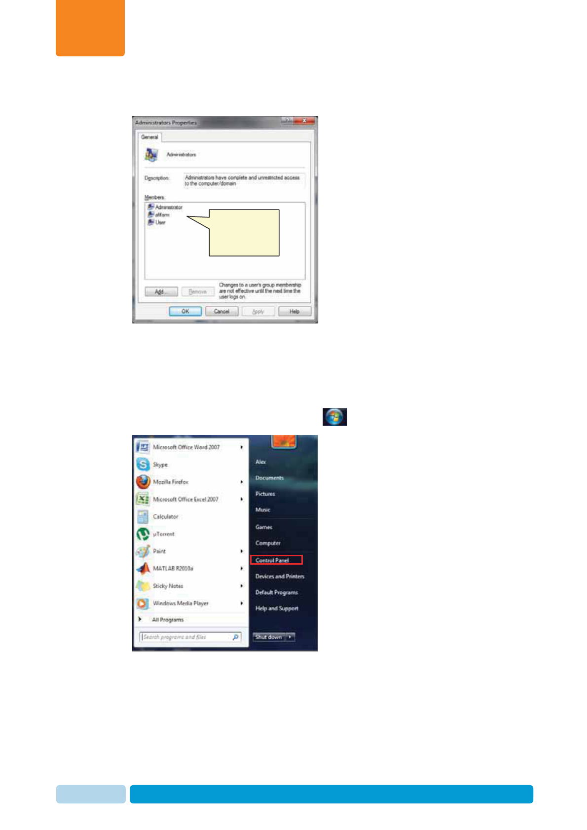
6. In the Administrators Properties window, verify that the user name under which
you logged-in appears in the list of Administrators in the Members box.
7. If the user name under which you logged-in does not appear, log-out, and log-in
under an administrator user name.
2.4.4.2 Configure Power Settings
1. In your system tray, click the Start icon , and select Control Panel
Verify the user
you are using
appears in this
list.
Prerequisites and Site Planning
Chapter
2
Oct 2013 AfiAct II™ Installation Manual30
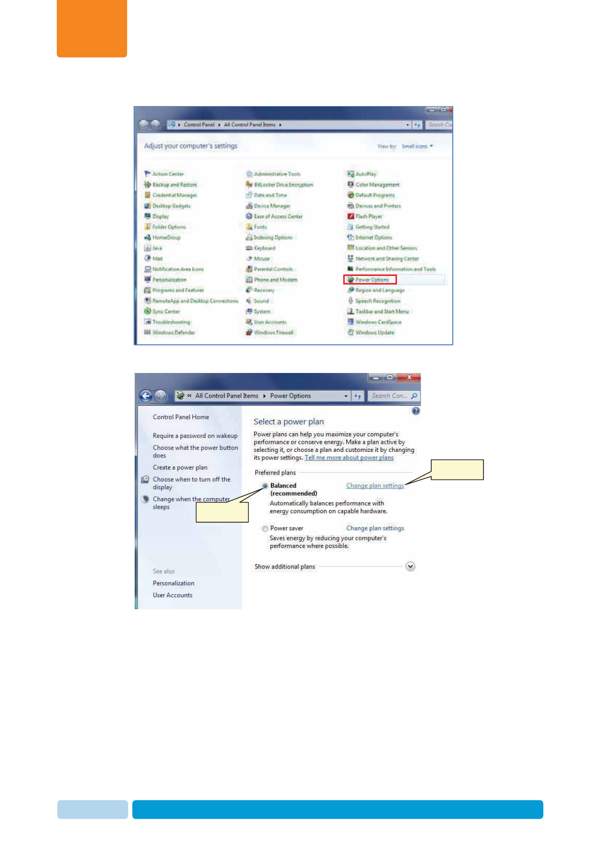
2. Click Power Options.
3. Checkmark Balanced and click Change plan settings.
Checkmark
Click
Prerequisites and Site Planning
Chapter
2
Oct 2013 AfiAct II™ Installation Manual31
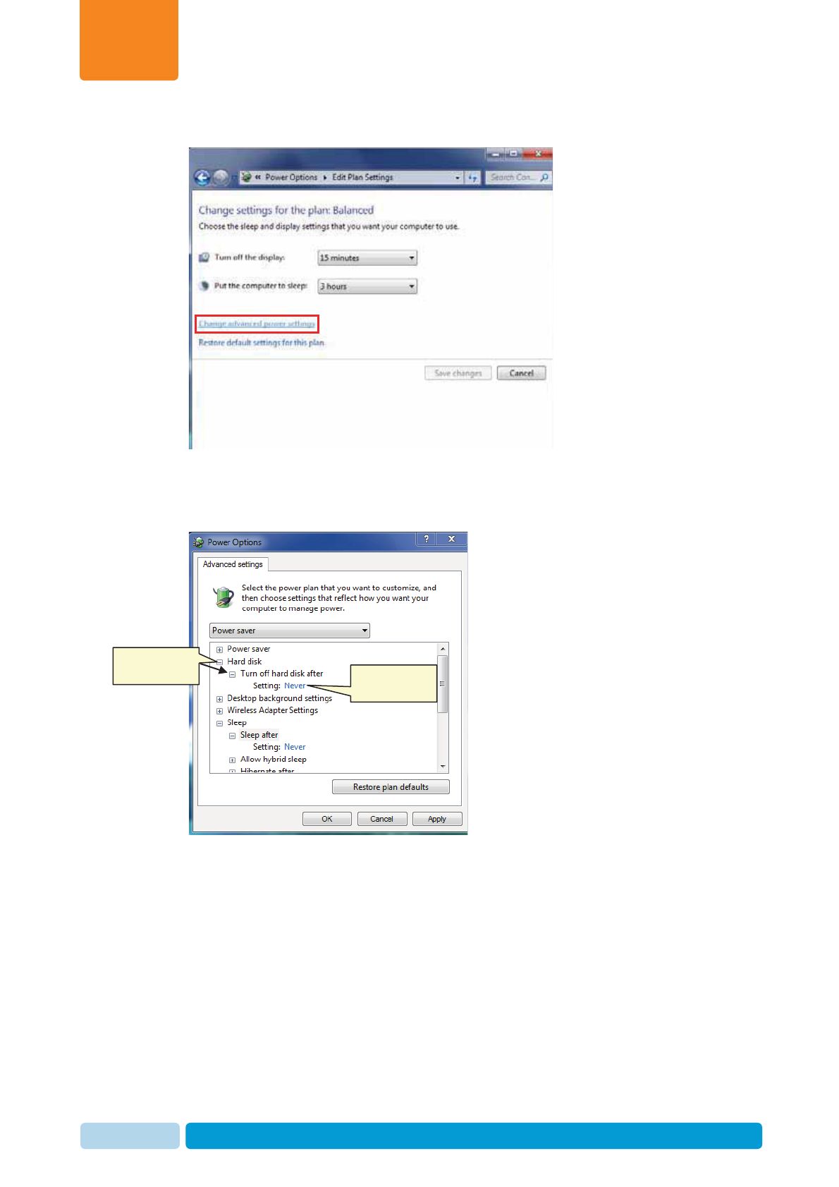
4. Click Change advanced power settings.
5. Expand the Hard disk folder (click the +sign near the folder). Then expand
Turn off hard disk after and change to Never.
6. Expand Sleep. Then expand Sleep after and change to Never.
Click to
expand folders Click to
change value
Prerequisites and Site Planning
Chapter
2
Oct 2013 AfiAct II™ Installation Manual32
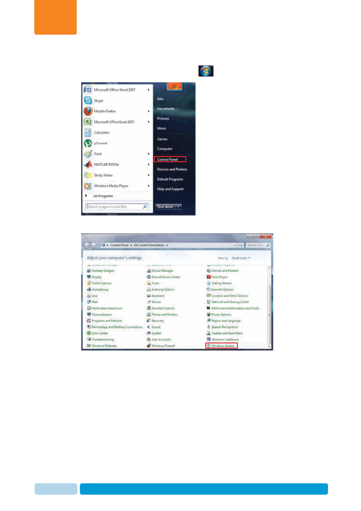
2.4.4.3 Install Windows Updates
1. In your system tray, click the Start icon , and select Control Panel
2. Click Windows updates
Prerequisites and Site Planning
Chapter
2
Oct 2013 AfiAct II™ Installation Manual33
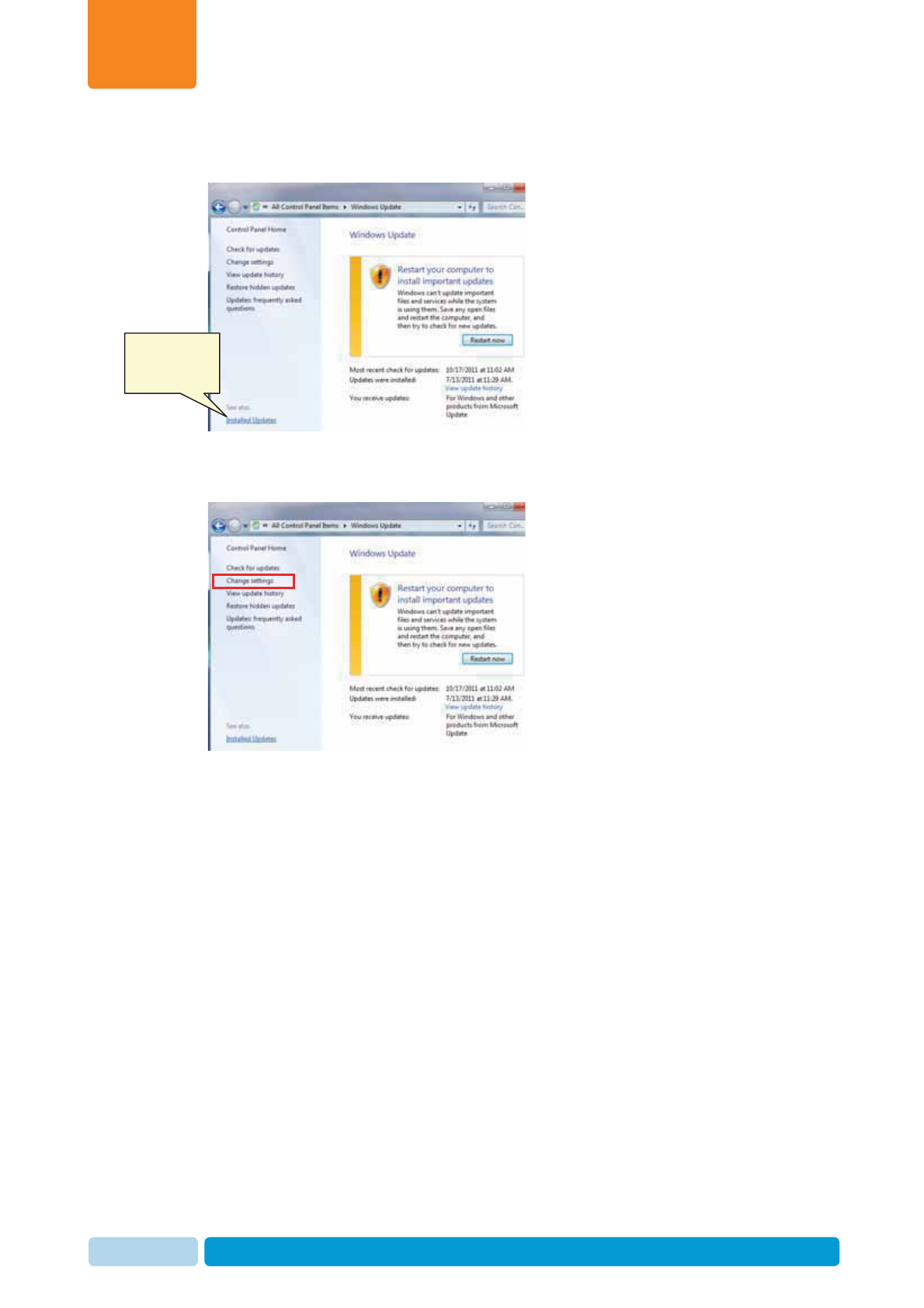
3. Click Install updates and follow the windows wizard to install all available
updates.
4. Click Change settings.
Click to install
windows
updates
Prerequisites and Site Planning
Chapter
2
Oct 2013 AfiAct II™ Installation Manual34
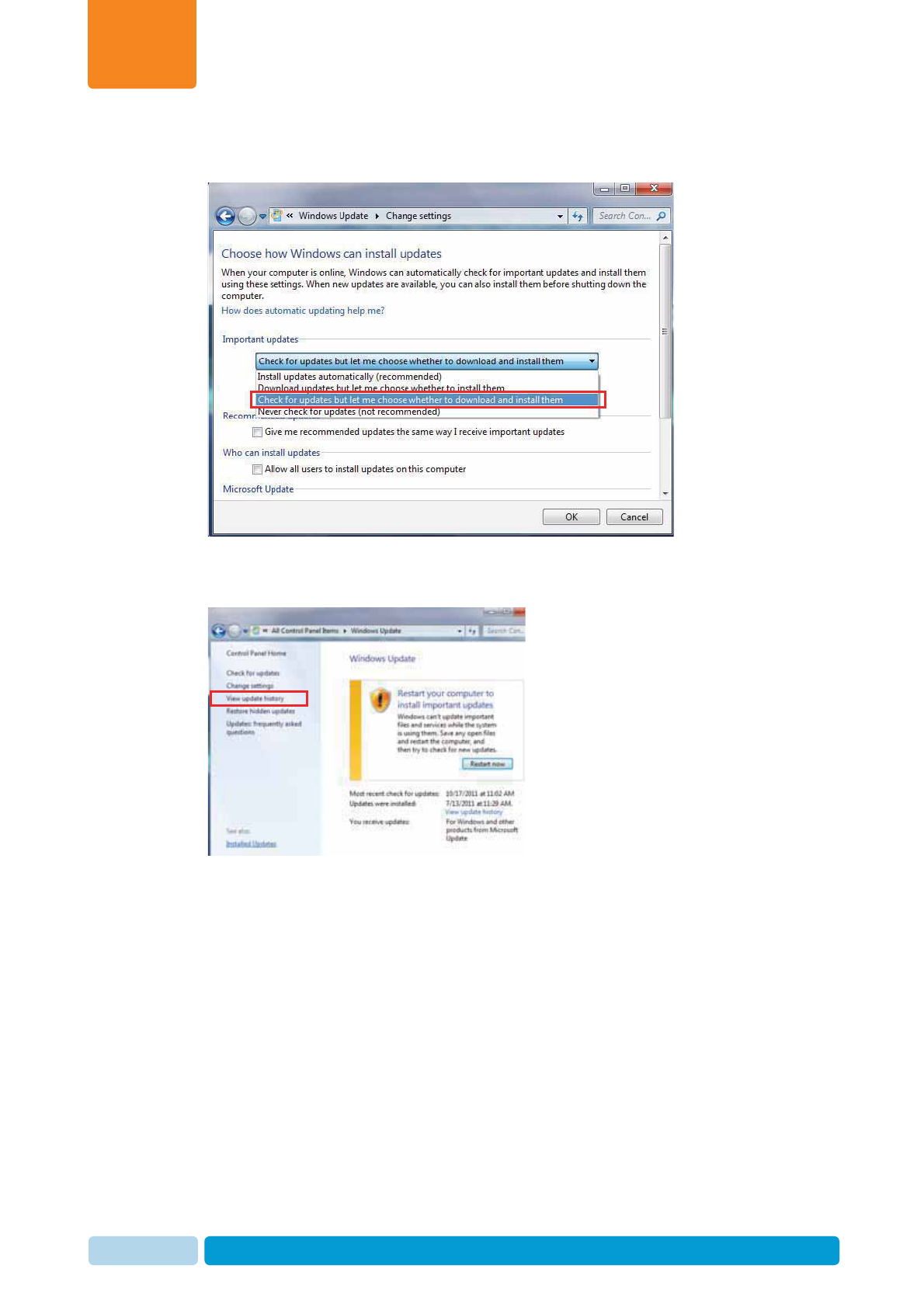
5. In the displayed dialog, choose Check for updates but let me choose whether to
download and install them.
6. Click OK to return to Windows update dialog.
7. Click View update history.
8. Check the status column for any problems and fix if necessary (refer to vendor
instructions).
Prerequisites and Site Planning
Chapter
2
Oct 2013 AfiAct II™ Installation Manual35
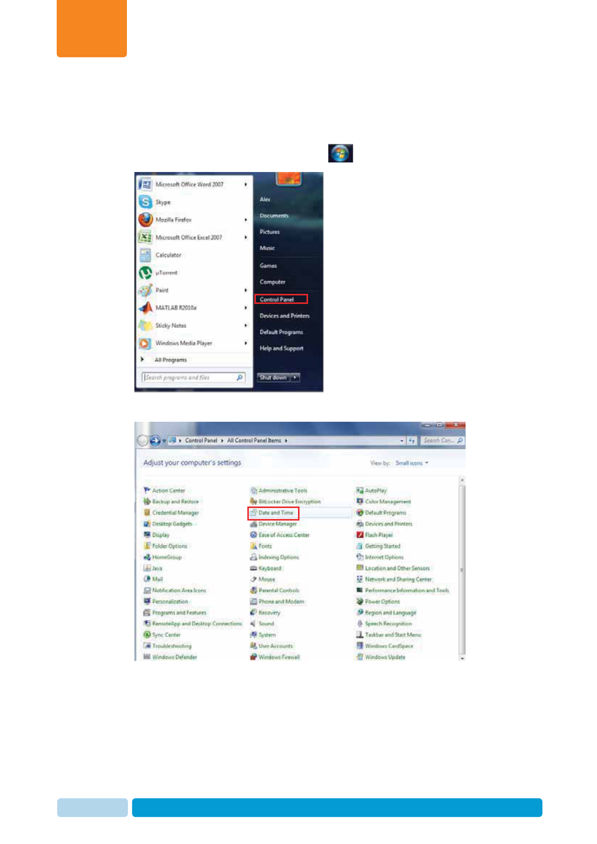
2.4.4.4 Set the Time and Synchronization
Disable the synchronization with the internet time server and check the time zone
settings as follows:
1. In your system tray, click the Start icon , and select Control Panel
2. Click Date and Time
Prerequisites and Site Planning
Chapter
2
Oct 2013 AfiAct II™ Installation Manual36
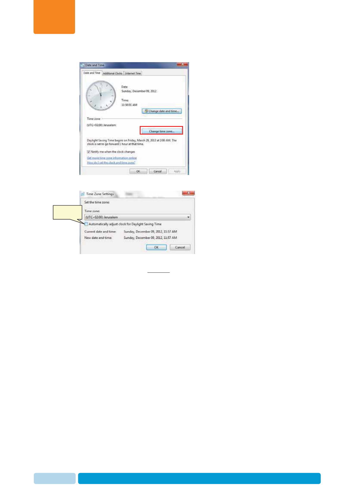
3. Click Change time zone
4. Uncheck Automatic adjustment of daylight saving Time.
5. Verify that the time zone settings are identical in all the used PCs (in a multi PC
system) (in the above example, all PCs should be set to the same time zone
UTC+02:00)
Uncheck
Prerequisites and Site Planning
Chapter
2
Oct 2013 AfiAct II™ Installation Manual37
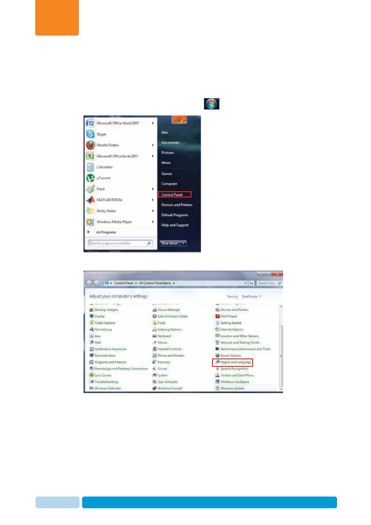
2.4.4.5 Verify Regional Parameters Configuration
For multiple PCs (integrated mode with AfiFarm systems) only: Check that the
Region and Language settings are identical for all the PCs used (in multi PC
system).
1. In your system tray, click the Start icon , and select Control Panel
2. Click on Region and Language.
Prerequisites and Site Planning
Chapter
2
Oct 2013 AfiAct II™ Installation Manual38
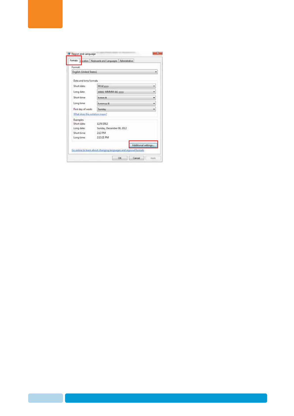
3. Choose the Formats tab and click Additional settings.
4. Record the settings and verify that all recorded attributes are identical for all the
PCs used.
5. Click OK to return to the Region and Language dialog.
6. Click the Location tab. Record the settings and verify that all recorded
attributes are identical for all the PCs used.
7. Click OK to return to the Region and Language.
8. Click Administrative tab. Record the settings and verify that all recorded
attributes are identical for all the PCs used.
Prerequisites and Site Planning
Chapter
2
Oct 2013 AfiAct II™ Installation Manual39
2.4.4.6 Confirm the File Sharing and Network Discovery
Verify proper file sharing setup as follows (for a multi PCs system):
1. In your system tray, click the Start icon , and select Control Panel
2. Click on Network and sharing center.
Prerequisites and Site Planning
Chapter
2
Oct 2013 AfiAct II™ Installation Manual40
3. Click Change advanced sharing settings.
4. Expand Home or Work (click the arrow )
5. Verify the following attributes are turned ON:
x Network discovery is ON.
x File and printer sharing is ON.
x Access to read and write files in Public folders for anyone with network
access is ON.
x Using user accounts and passwords to connect to other computers is ON.
Expand
Turn ON
Prerequisites and Site Planning
Chapter
2
Oct 2013 AfiAct II™ Installation Manual41
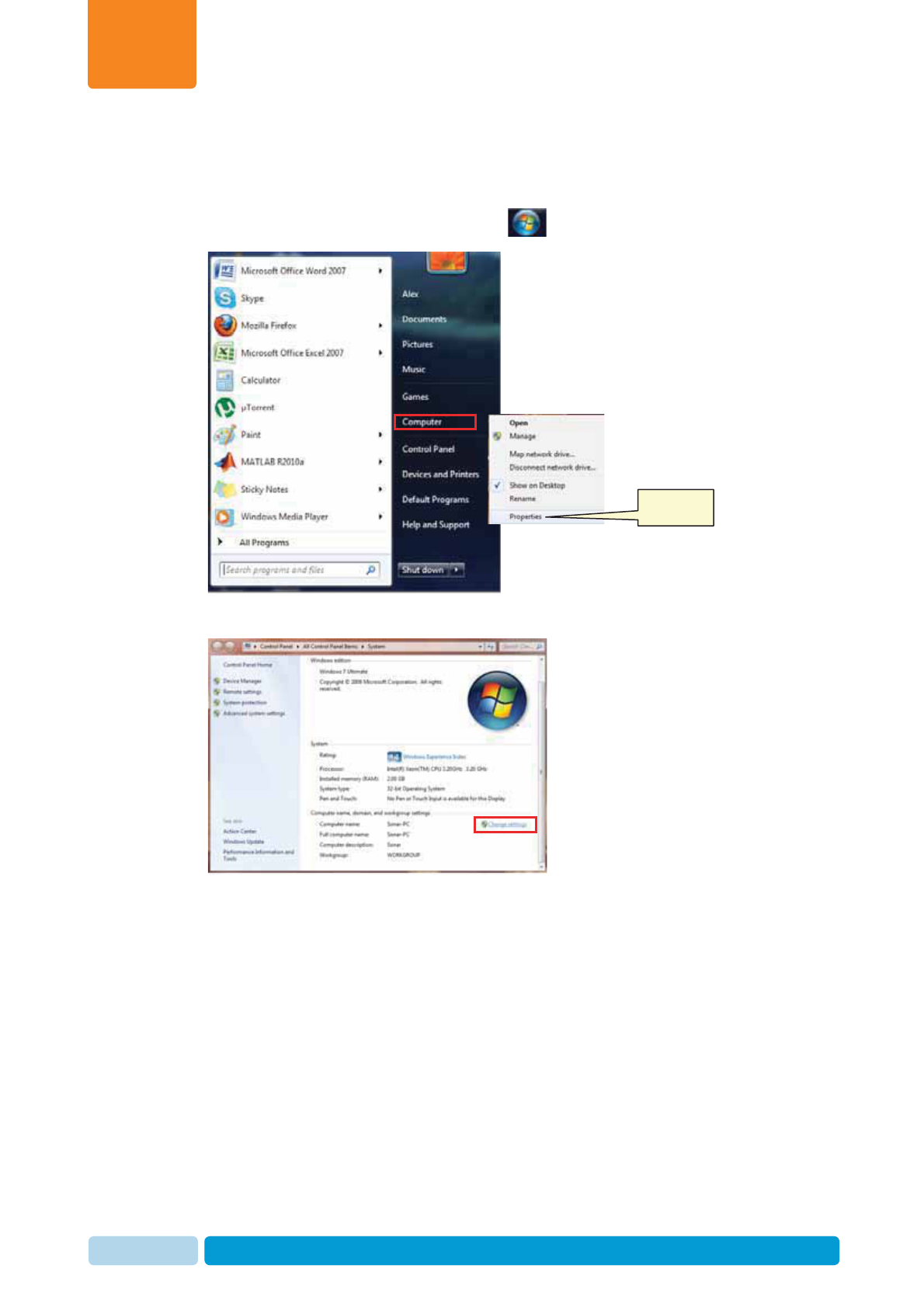
2.4.4.7 Verify Unique PC Names
Verify that all of the systems PCs have a Unique PC Name as follows:
1. In your system tray, click the Start icon , and right click on Computer.
2. Click Properties. The computer basic information dialog appears.
Click
Prerequisites and Site Planning
Chapter
2
Oct 2013 AfiAct II™ Installation Manual42
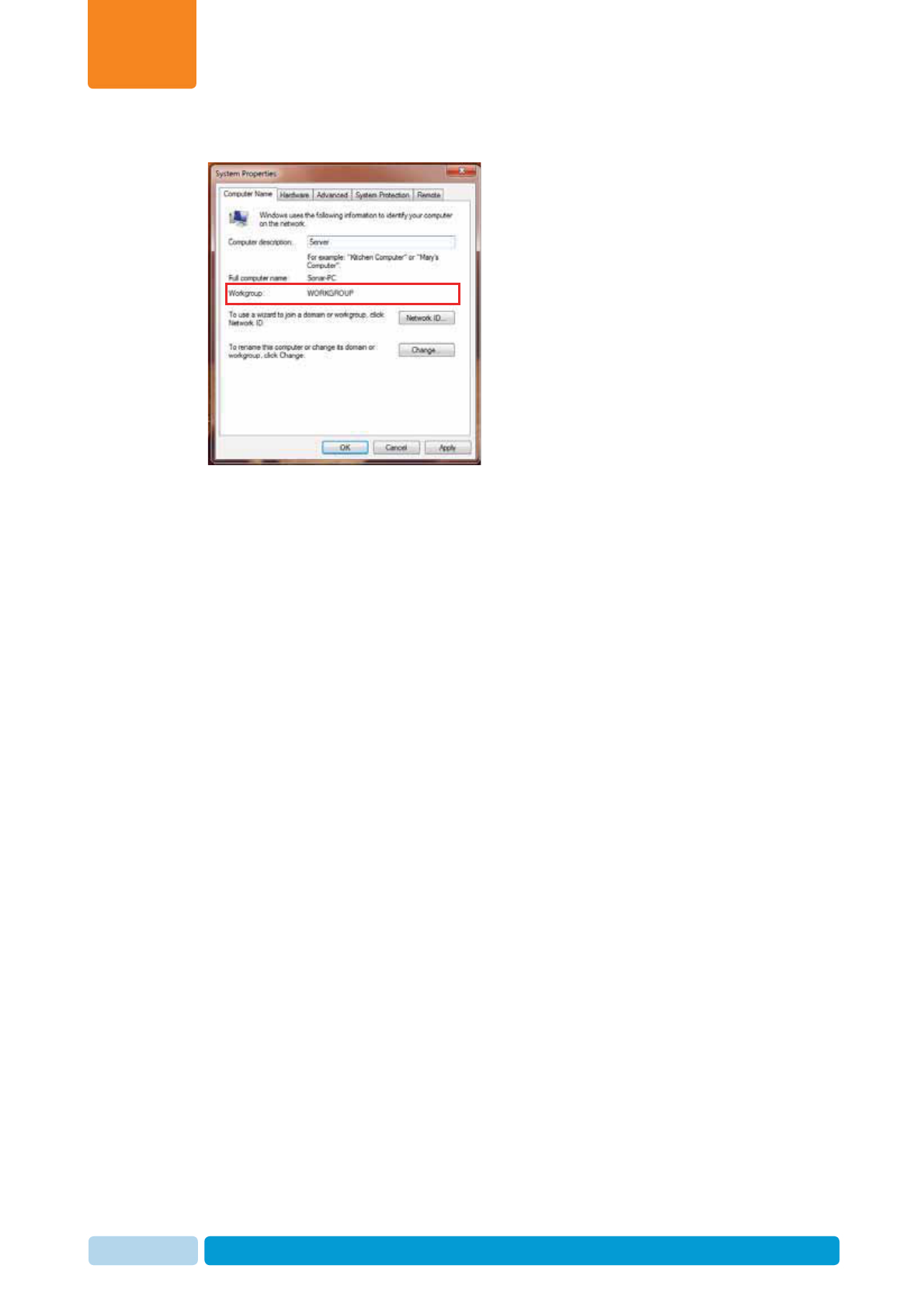
3. Click on Change settings.
4. In the Computer description field, write a meaningful PC name (e.g. “Server”,
“Controller”, or “Client 1”,”Client 2”...).
5. Click OK

Prerequisites and Site Planning
Chapter
2
Oct 2013 AfiAct II™ Installation Manual43
2.4.4.8 Verify Windows Firewall is Configured
Note: Only Windows Firewall is supported. Ensure that no other Antivirus or Firewall
systems are installed.
Before the installation, the required rules are automatically enabled in WIN firewall,
to allow the system to run properly with this FW on.
2.4.5 Verify System is Prepared
As the successful completion of the installation process is strongly dependent on the
environmental preparations previously performed, it is essential at this phase,
before starting to install the system, that the user performs preparations checkup.
Review the pre-requisites list and verify that all of them were implemented.
What Next?
Your system is now ready for installation.
Assemble the Reader Basic Elements
Chapter
3
Oct 2013 AfiAct II™ Installation Manual44
3 Assemble the Reader Basic Elements
Before proceeding with the installation steps, the basic Reader assembly is
performed. This includes:
x Reader antennas
x Reader’s bracket plate
To assemble the Reader basic elements
1. Open the Reader and the power-supply boxes, and verify that all of the
elements are available (see 1.2.1, 1.2.2)
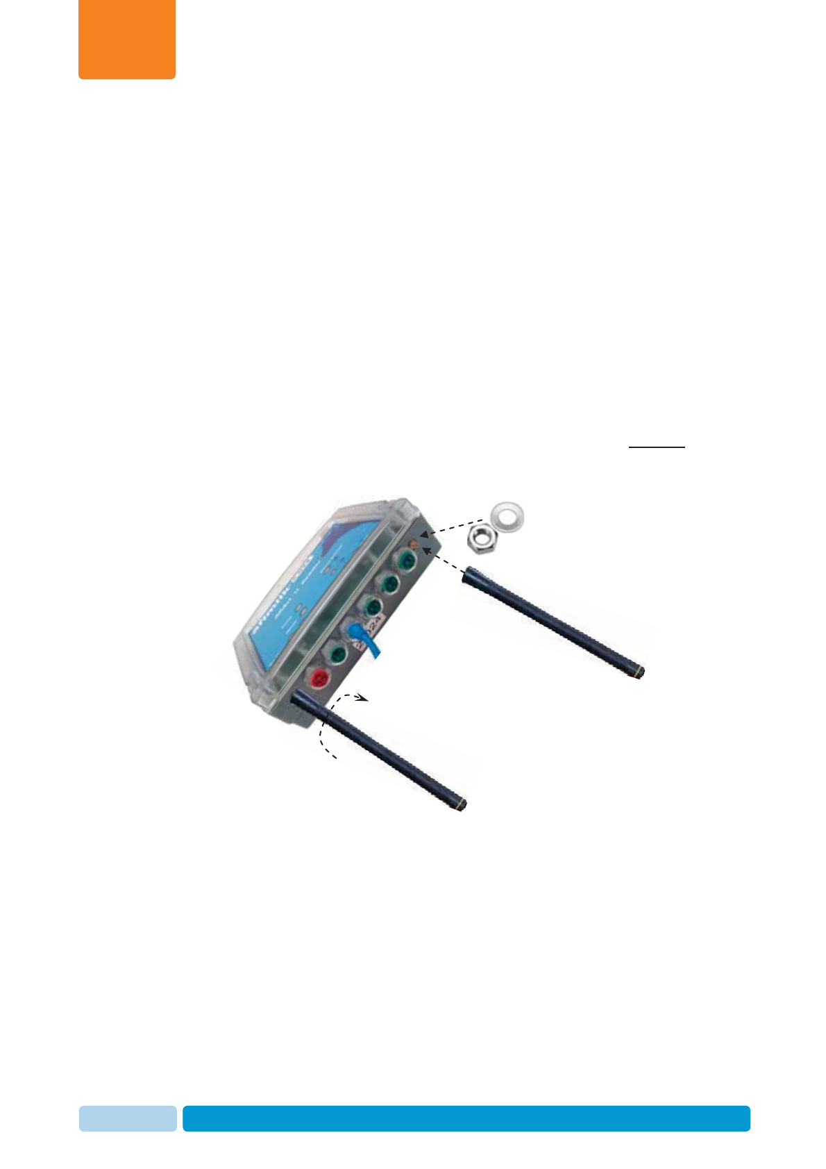
2. Connect the Lower LR Antennas:
a. Place the nut and washer on the Reader’s lower antenna connectors
(located on the panel with the blue electricity cable).
b. Insert the antennas into the outer connectors and screw them in GENTLY
but tightly (turn them clockwise). Make sure the antennas are fastened "all
the way" and are stable.
Assemble the Reader Basic Elements
Chapter
3
Oct 2013 AfiAct II™ Installation Manual45
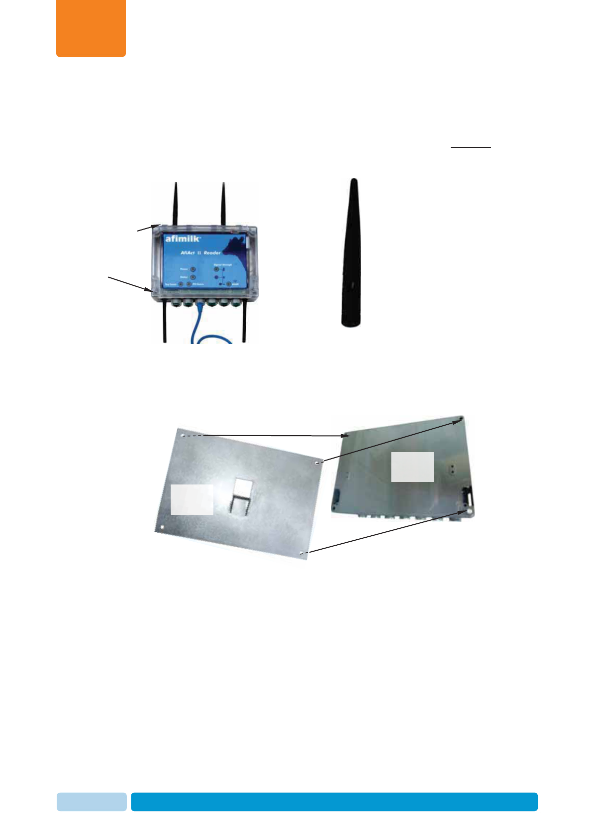
3. Connect the upper antennas (see 1.2.1) to the upper Reader connectors:
a. Place the nut and washer on the Reader’s upper antenna connectors
(located on the panel without the blue electricity cable).
b. Insert the antennas into the outer connectors and screw them in GENTLY
but tightly (turn them clockwise). Make sure the antennas are fastened "all
the way" and are stable.
4. Connect the bracket plate to the Reader’s back:
x Place the bracket plate at the back side of the Reader (bracket’s projecting
part facing away from Reader), aligning the screw holes of both elements.
Reader’s
back
Bracket
plate
Lower panel
Upper panel
Assemble the Reader Basic Elements
Chapter
3
Oct 2013 AfiAct II™ Installation Manual46
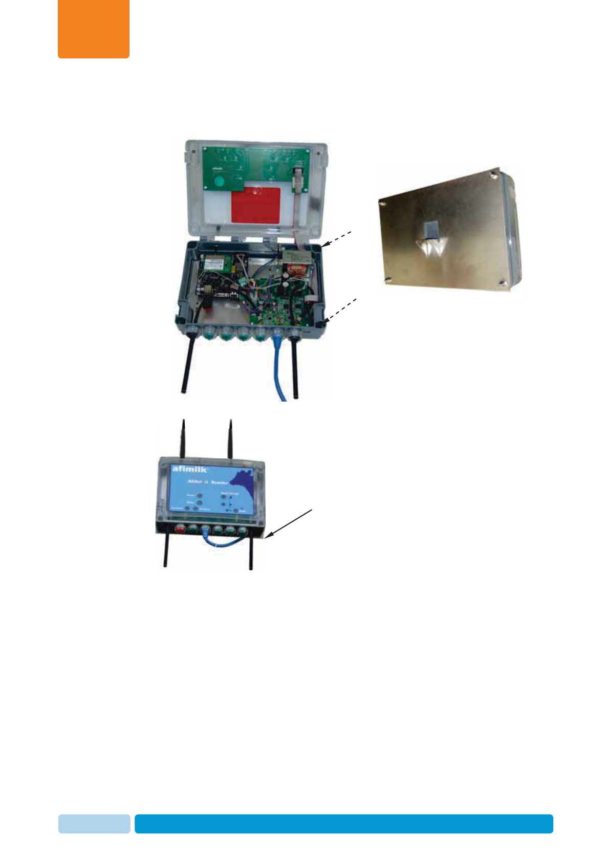
x Open the Reader enclosure (ensure the power is disconnected), and use
the provided Allen screws (PN) and nuts to screw the plate and the Reader
together.
5. Close the Reader enclosure.
Connected
bracket plate

Install and Set AfiAct II Software
Chapter
4
Oct 2013 AfiAct II™ Installation Manual47
4 Install and Set AfiAct II Software
AfiAct II software is installed on a single PC. It consists of two installed modules:
xAfiFarm5 – contains the AfiAct II program and reports. In farms that do
not use other AfiFarm elements, the data entry screens and activities are also
accessed through this component.
x Afimilk RT System module – this module controls and monitors the
system and collects data from the animals through the Reader.
This chapter details the installation phases of the two modules:
1. Install AfiFarm5, see 4.1
2. Install the RT (Real Time) system, see 4.2
3. Configure the RT System mandatory parameters (quick start), see 4.3
4. For integrated mode with AfiFarm systems only: Install the sync-agent in the
existing AfiFarm4, see 4.4
4.1 Install AfiFarm5 Module
This section details the AfiAct II installation steps, as performed by following the
instructions of the installation wizard. To install AfiFarm5 follow these steps:
1. Review general notes before starting, see 4.1.1
2. Initiate the installation wizard, see 4.1.2
3. Install the HASP (software license key)
firewall, database elements, see 4.1.3
4. Supervise the automatic installation steps, see 4.1.4
4.1.1 General Notes
Before starting, review the following general notes.
Installation time
The installation time varies according to the specific PC characteristics and specific
issues or wrong configurations. Generally: clean installations may take around 50
minutes.
Install and Set AfiAct II Software
Chapter
4
Oct 2013 AfiAct II™ Installation Manual48
Process sub-steps
During the installation, the wizard automatically performs several steps, as required
by the specific scenario. These include the installation of various components (SQL,
.Net 4, drivers, database operations, configurations, etc.).
Note: In AfiAct II’s AfiFarm5, the AfiFarm configuration is done via the RT System.
While the main steps for the configuration are described in this manual (see
Appendix C), an additional and more detailed description of the tool usage is
provided in the RT System configuration manual (see referred documents, page vii).
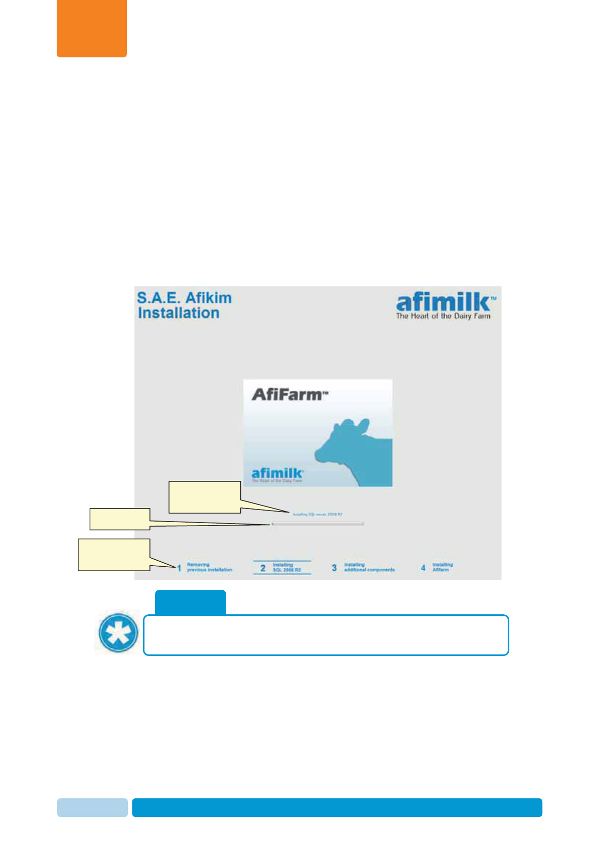
Installation dialog layout
The following main dialog appears during the installation, displaying various
messages and indications, allowing the user to follow the background phases. In
addition, the lower area provides information on the overall installation progress:
NOTE
The installation procedure might vary slightly for different operating systems.
Event currently in
progress
Progress bar
Current
installation phase
Install and Set AfiAct II Software
Chapter
4
Oct 2013 AfiAct II™ Installation Manual49
4.1.2 Set & Initiate the Installation Wizard
After verifying your PC is prepared for installation (see 2.4.5), initiate the installation
wizard according to the following steps.
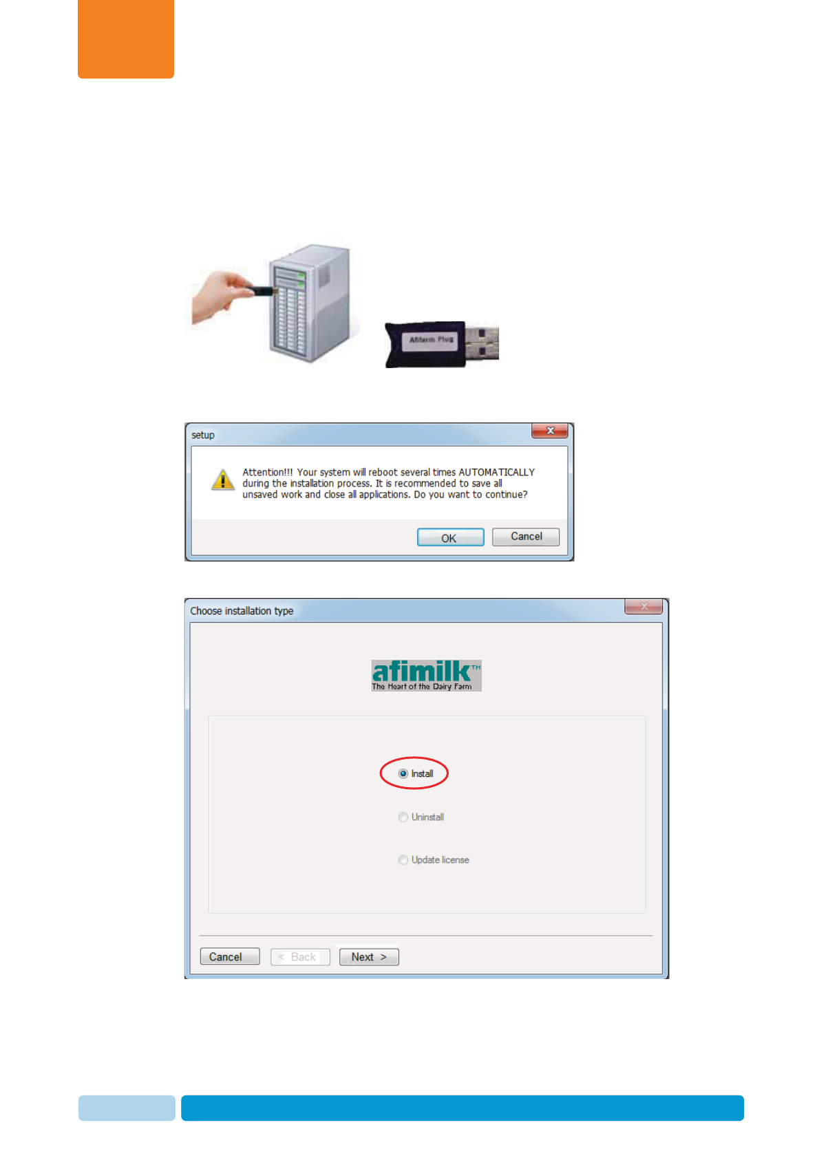
1. Insert the provided AfiFarm5 HASP USB key into the USB port of the PC.
2. Open AfiFarm5 DVD and double-click on the installation file: setup.exe. The
installation wizard is launched and the following message appears:
3. Click OK. The installation type dialog opens: choose Install.
Install and Set AfiAct II Software
Chapter
4
Oct 2013 AfiAct II™ Installation Manual50
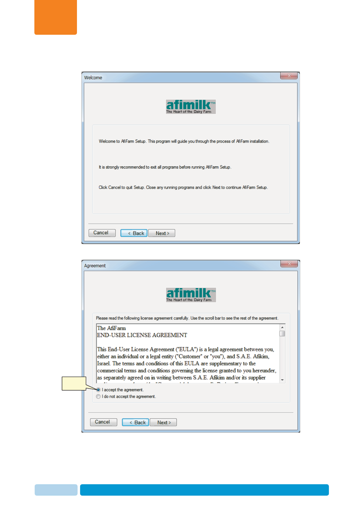
4. Click Next. The welcome dialog opens. Make sure you close any programs
running in the background.
5. Click Next. The License Agreement dialog opens
Select
Install and Set AfiAct II Software
Chapter
4
Oct 2013 AfiAct II™ Installation Manual51
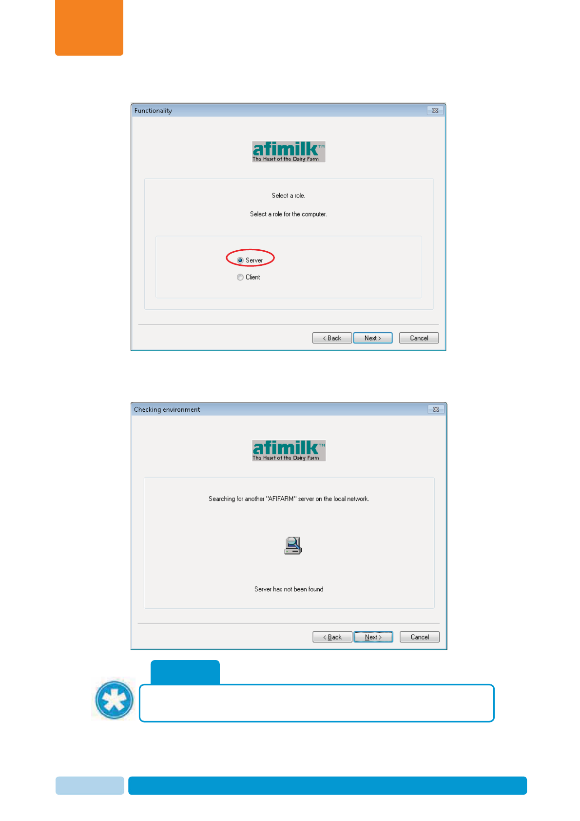
6. Select I accept the agreement and click Next. The Functionality dialog opens
7. Choose Server and click Next. The system searches the local network to
ensure there are no other servers found. When done searching, the Next button
becomes available.
NOTE
If a server has been detected, the problem must be resolved before
continuing the installation. Contact afimilk helpdesk, see page ii.
Install and Set AfiAct II Software
Chapter
4
Oct 2013 AfiAct II™ Installation Manual52
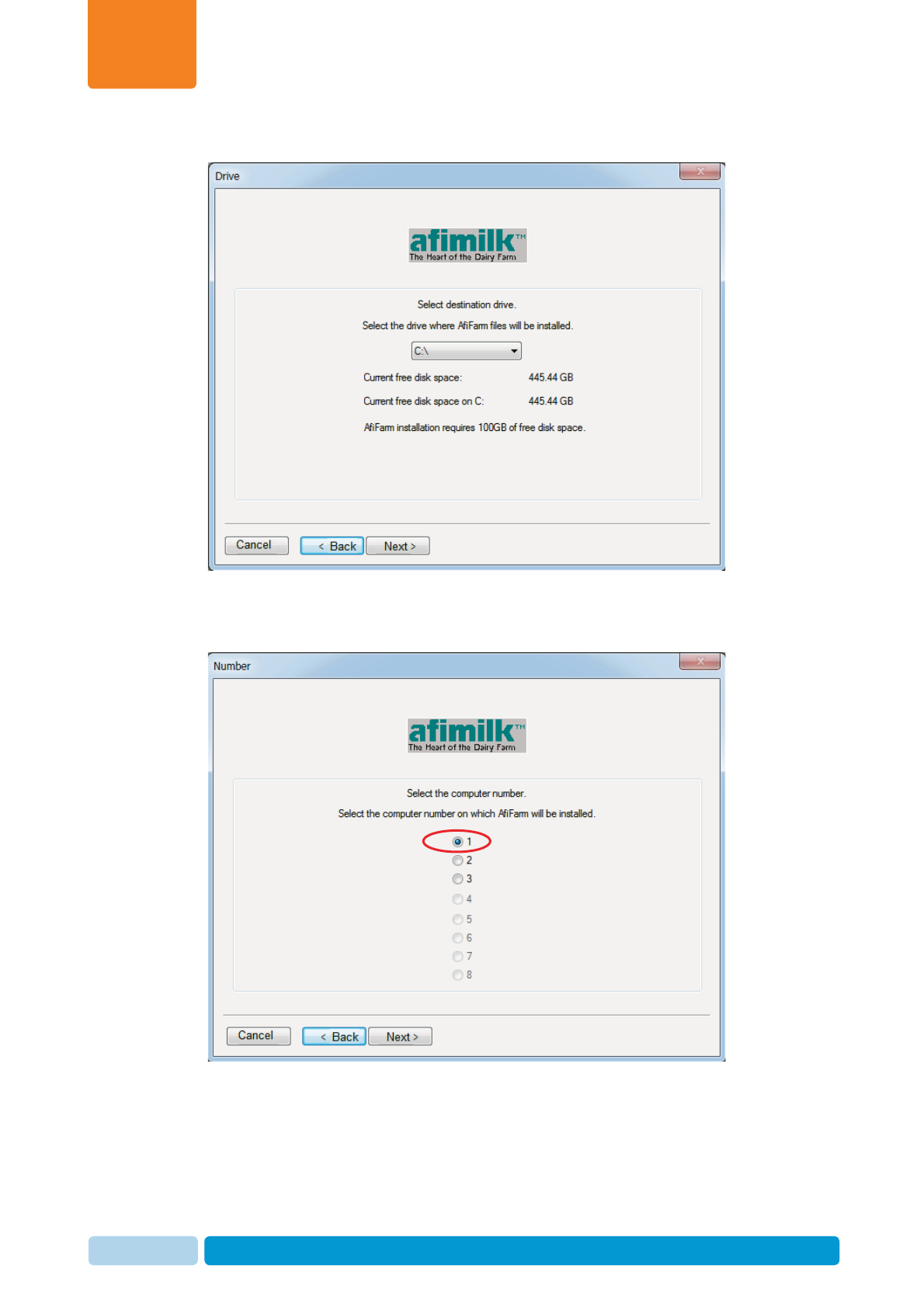
8. Click Next. The Drive dialog opens.
9. Select the hard drive where AfiFarm files are to be installed. This is the hard
drive previously prepared, where there are at least 100GB of free space
available (see 2.4.2.2). Click Next. The Number dialog opens:
Install and Set AfiAct II Software
Chapter
4
Oct 2013 AfiAct II™ Installation Manual53
10. Select a unique computer number for the computer you are installing
(default: #1)
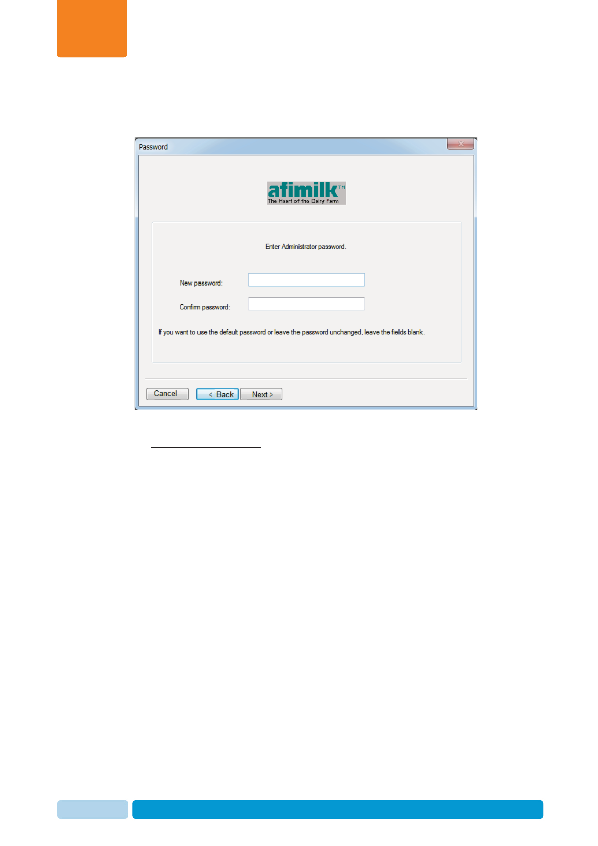
11. Click Next. The Password dialog opens, where the default password is afi.
12. To keep your existing password: do not type any value into the boxes.
To change the password: type the new password. Then re-type your password
in the Confirm password box.
Install and Set AfiAct II Software
Chapter
4
Oct 2013 AfiAct II™ Installation Manual54
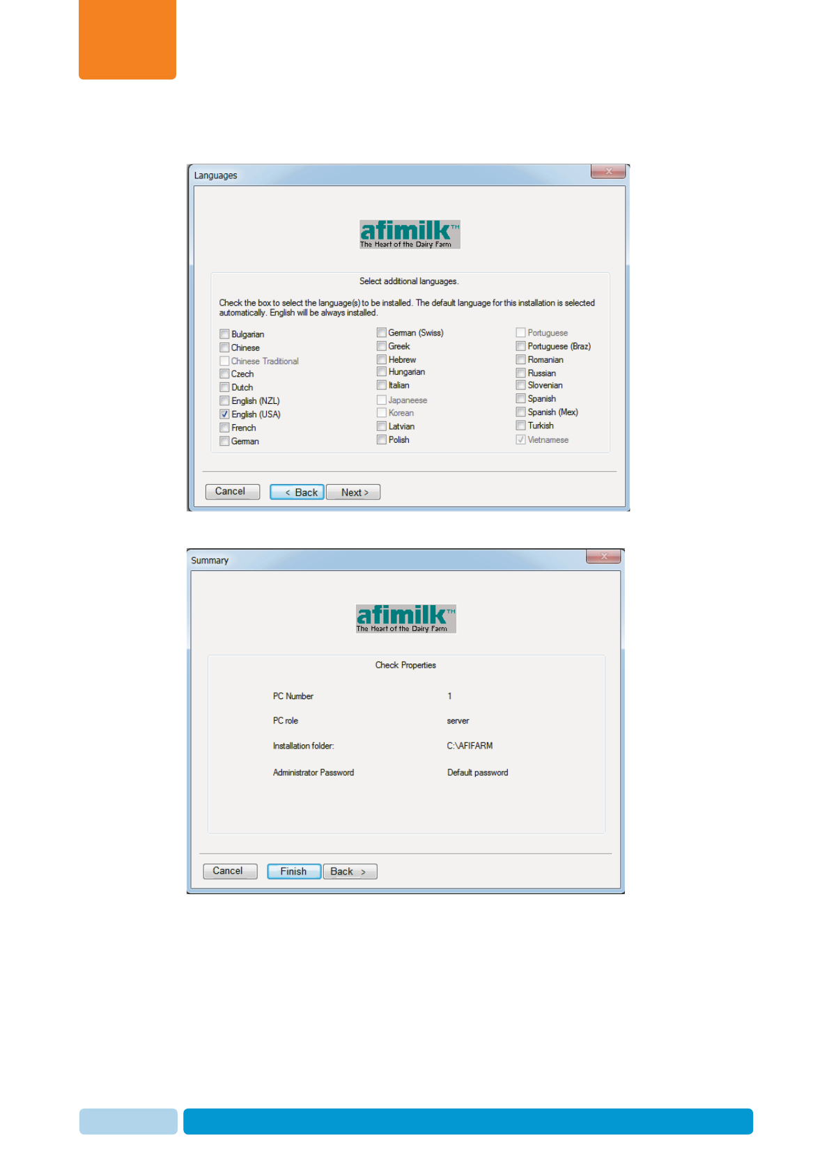
13. Click Next. The Language dialog opens, where the default language is check-
marked in gray (in the following example: Vietnamese).
14. Select the desired language(s) and click Next. The Summary dialog opens
Install and Set AfiAct II Software
Chapter
4
Oct 2013 AfiAct II™ Installation Manual55
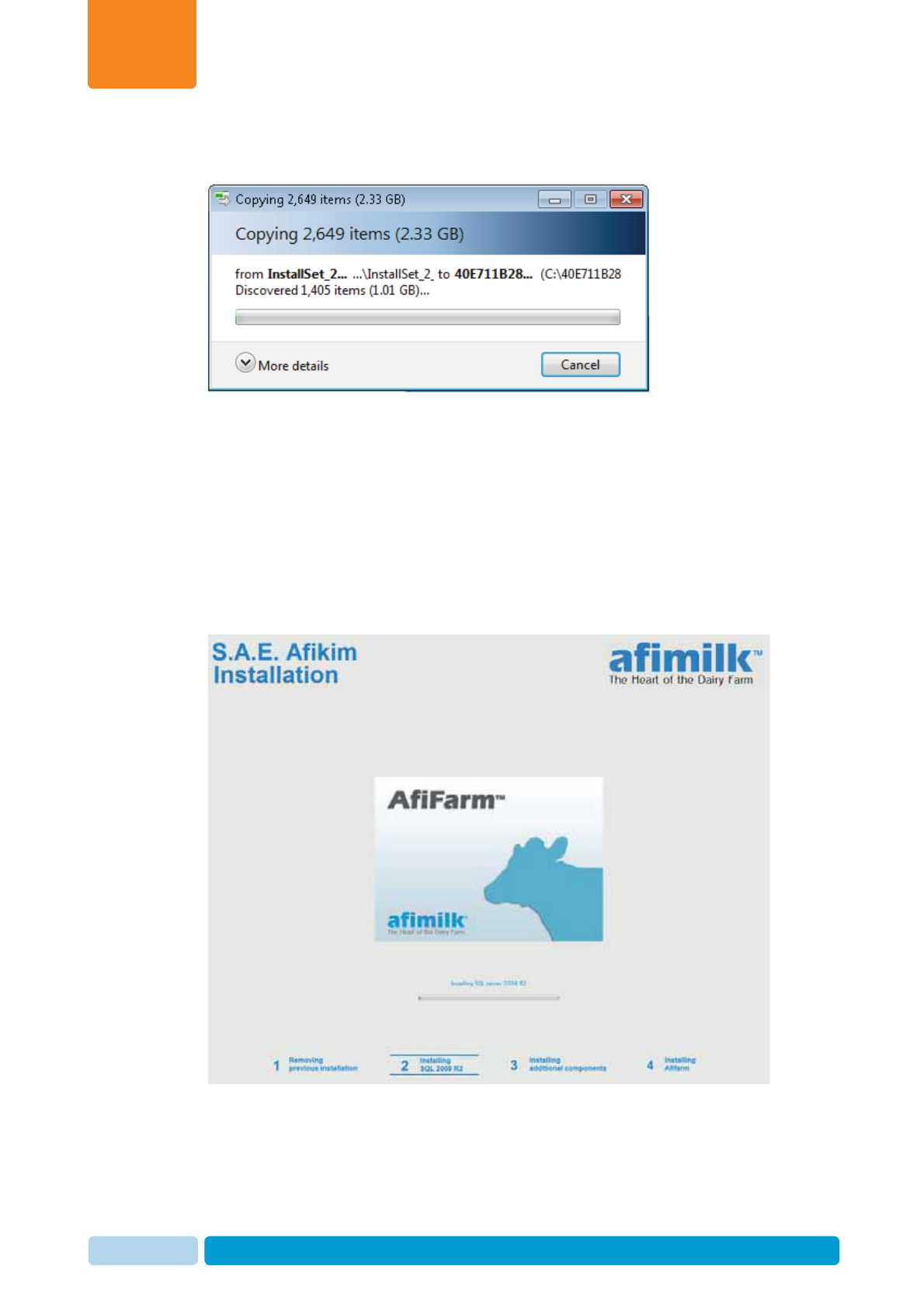
15. Click Finish. The automatic installation process starts, and the following dialog
appears. (This may take a few minutes).
What next?
The installation wizard will now automatically perform the required background
procedures. Verify that the process is done according to the following steps. If a
problem occurs, refer to the troubleshooting chapter, or contact afimilk Helpdesk
(see page ii for details).
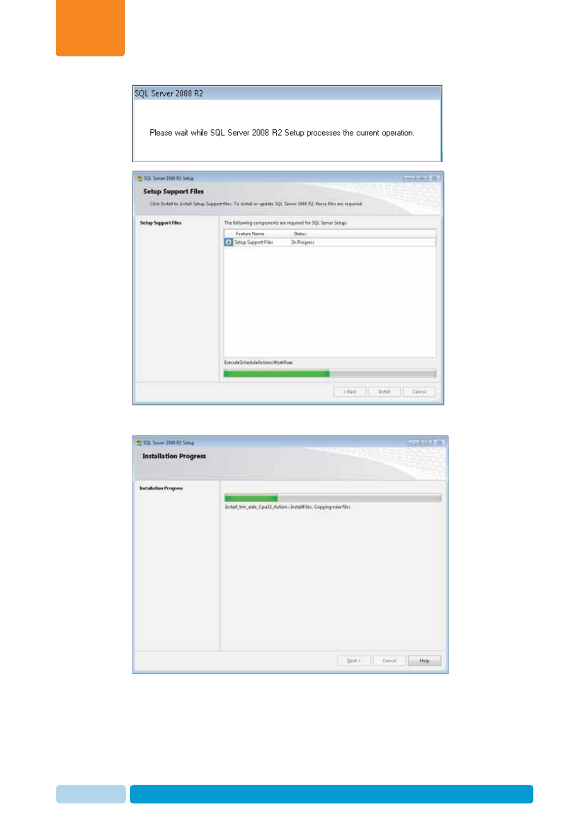
4.1.3 Install HASP, Firewall and Database Elements
1. The next screens indicate that the database is being installed. The SQL
installation may take 30-50 minutes.
Install and Set AfiAct II Software
Chapter
4
Oct 2013 AfiAct II™ Installation Manual56
Install and Set AfiAct II Software
Chapter
4
Oct 2013 AfiAct II™ Installation Manual57
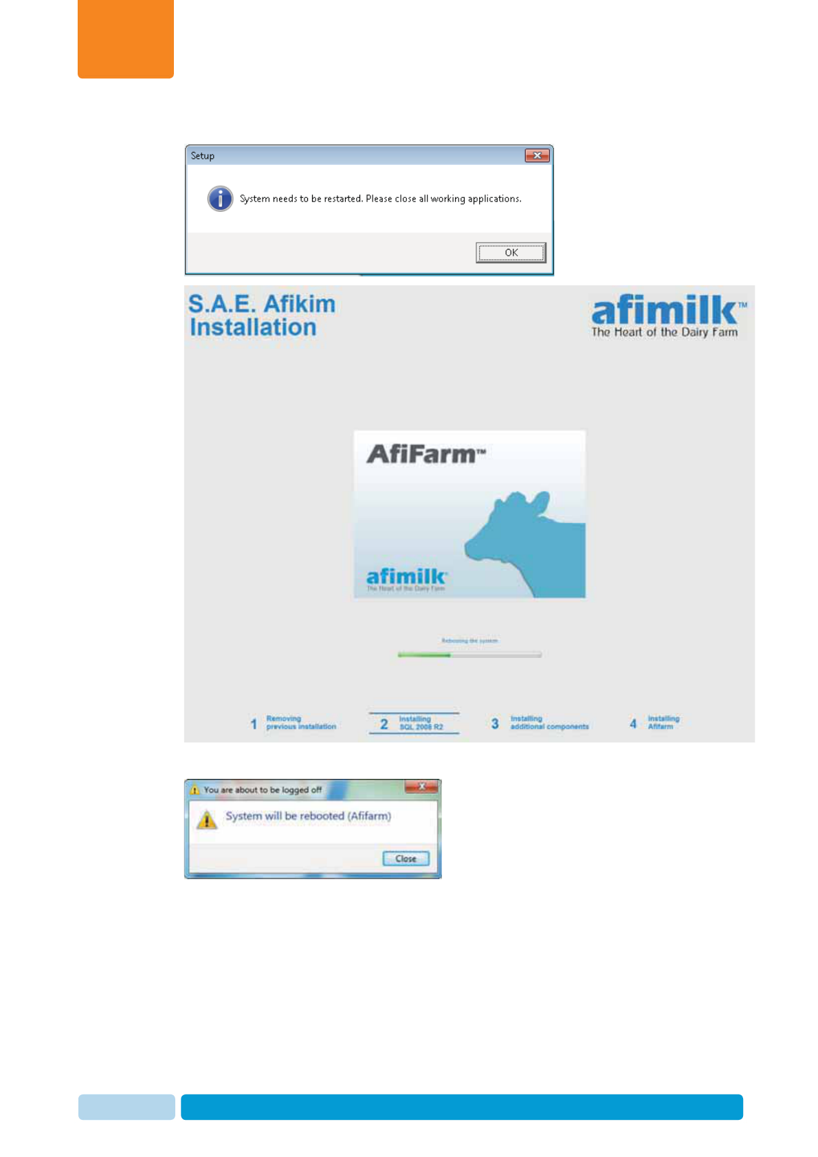
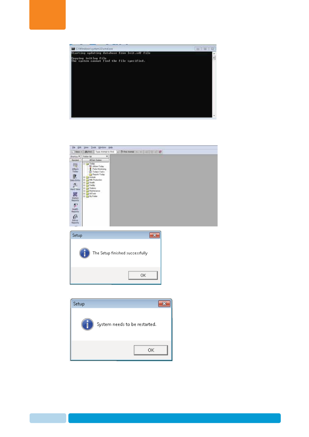
2. The system will need permission to restart: Click OK
3. Reboot notification appears
Install and Set AfiAct II Software
Chapter
4
Oct 2013 AfiAct II™ Installation Manual58
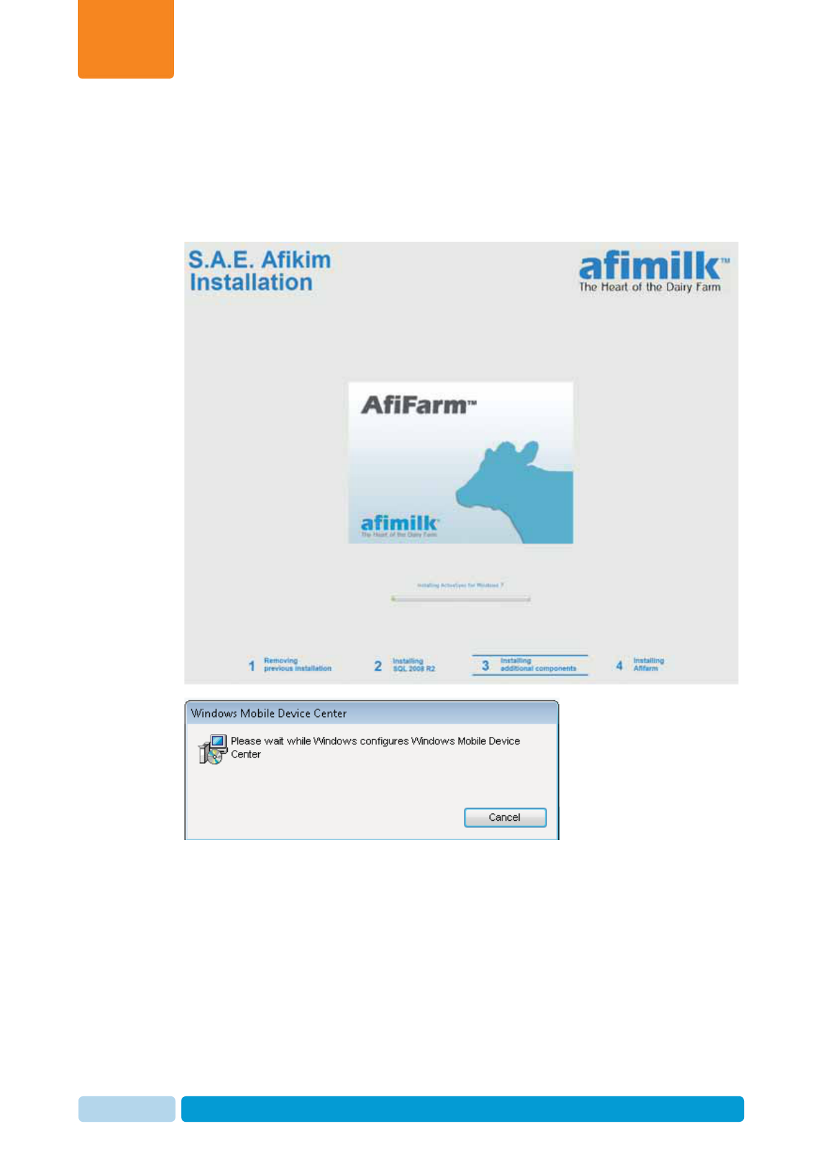
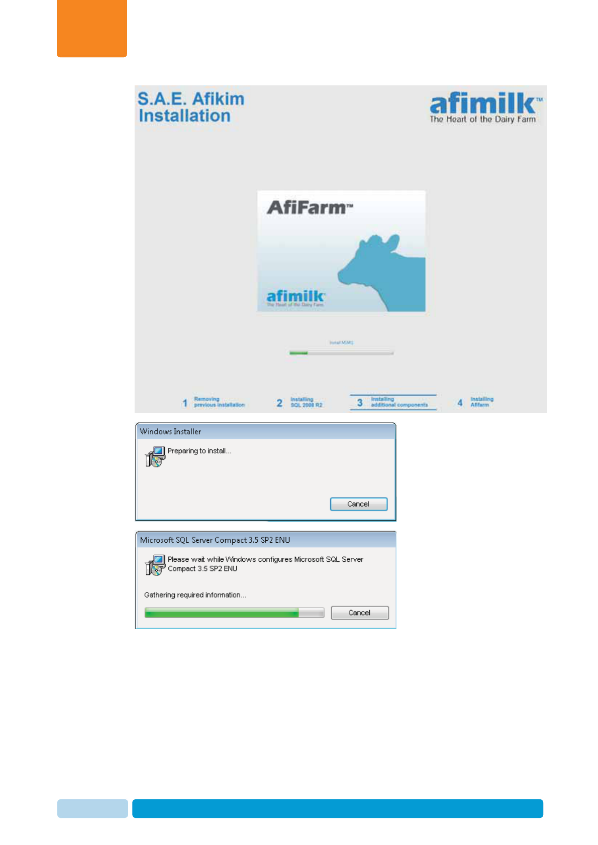
4.1.4 Supervise Automatic Installation Steps
1. After rebooting, the following dialogs appear, while the system installs the
required elements. This process may take 10-15 minutes. Make sure that the
progress bar shows (slow) progress. IMPORTANT! Do not touch any of the
screens shown below during the process!
Install and Set AfiAct II Software
Chapter
4
Oct 2013 AfiAct II™ Installation Manual59
Install and Set AfiAct II Software
Chapter
4
Oct 2013 AfiAct II™ Installation Manual60
Install and Set AfiAct II Software
Chapter
4
Oct 2013 AfiAct II™ Installation Manual61
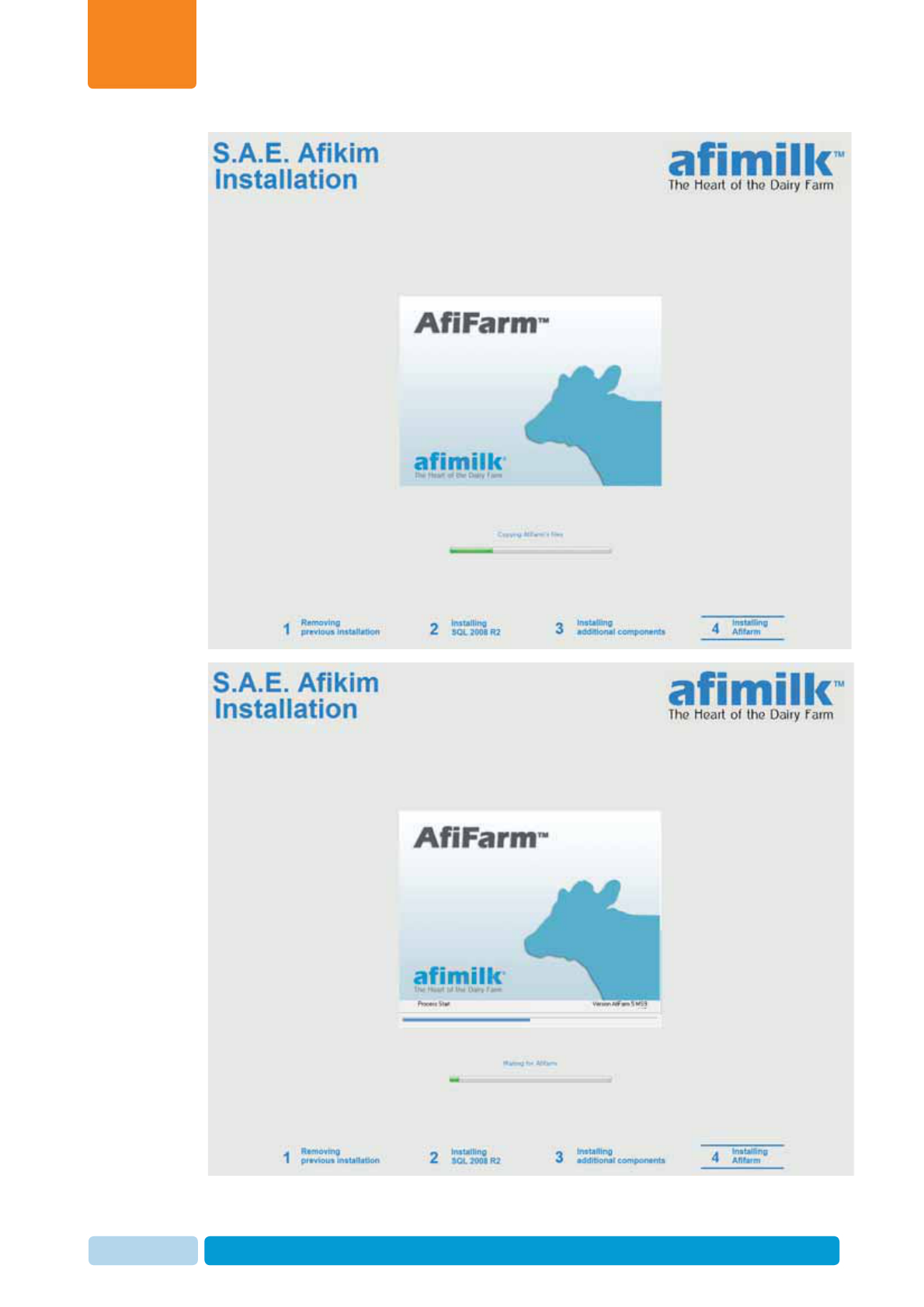
2. AfiFarm application will automatically be started by the system:
3. The installation process has been completed. Restart is required.
Install and Set AfiAct II Software
Chapter
4
Oct 2013 AfiAct II™ Installation Manual62
4.2 Install the AfiFarm RT System Module
After the AfiFarm5 is installed, install the AfiFarm RT (Real Time) System. The
AfiFarm RT System includes four elements that are installed separately. Three will
be installed now, and the fourth is installed at a later phase, after performing basic
system configuration.
Install the AfiFarm RT system according to the following steps:
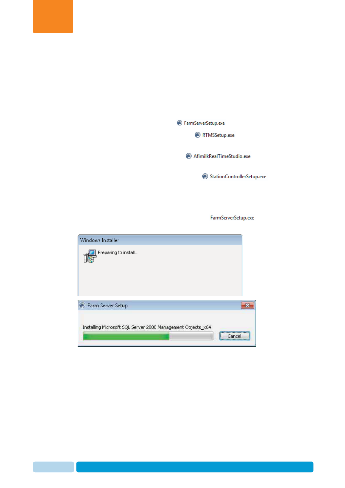
1. Install FarmServer Setup module: (~15 minutes), see 4.2.1
2. Install Real Time Setup (RTMS) module: (~10 minutes), see
4.2.2
3. Install Real Time GUI (RTG) module: (2-5 minutes),
see 4.2.3
4. Install Real Time Station Controller module: (2-5
minutes), see 4.2.4
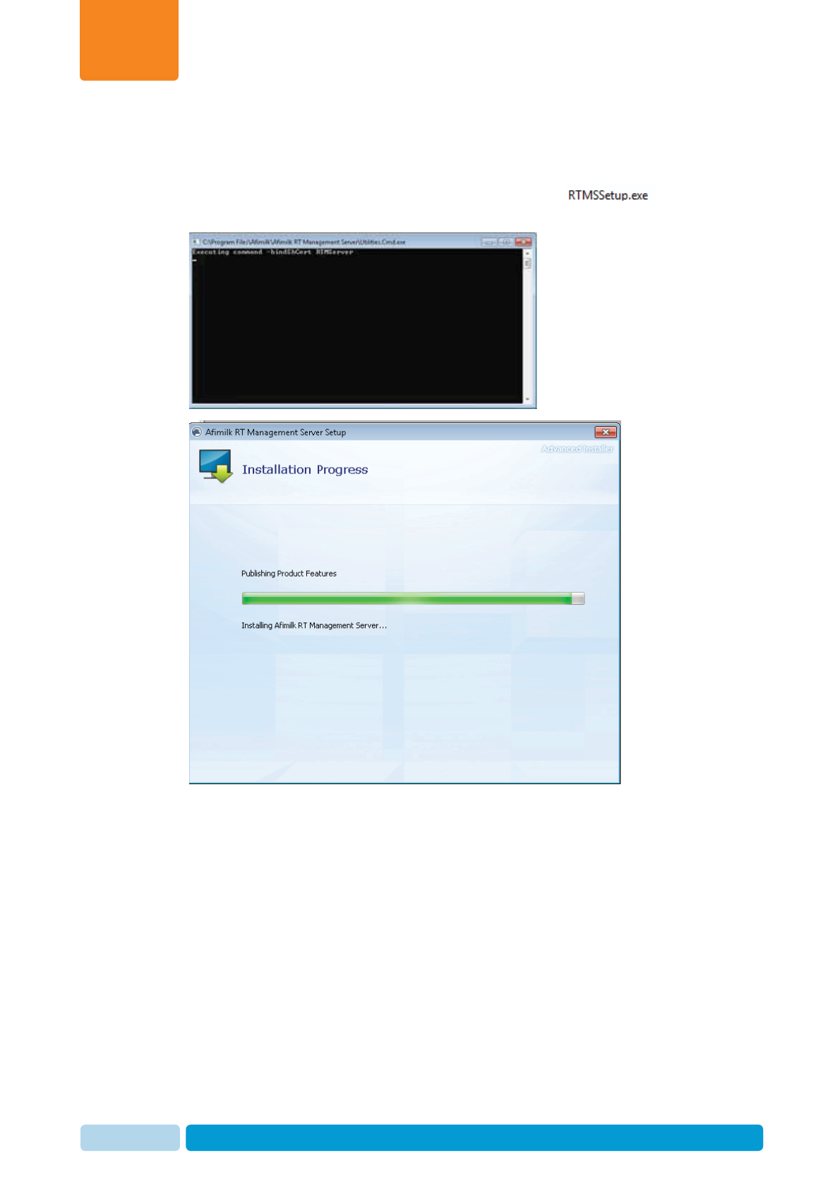
4.2.1 Install the Server Setup
1. Open the AfiFarmRT folder and double click on . The
following pre-installation screens are displayed:
Install and Set AfiAct II Software
Chapter
4
Oct 2013 AfiAct II™ Installation Manual63
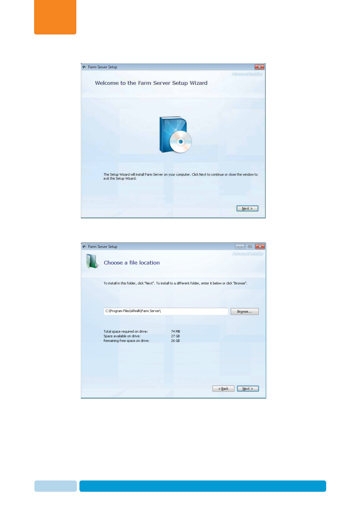
2. The setup wizard welcome screen appears. Click Next.
3. Select the location where the Farm server setup files are to be installed. The
default appears automatically. Click Next.
Install and Set AfiAct II Software
Chapter
4
Oct 2013 AfiAct II™ Installation Manual64
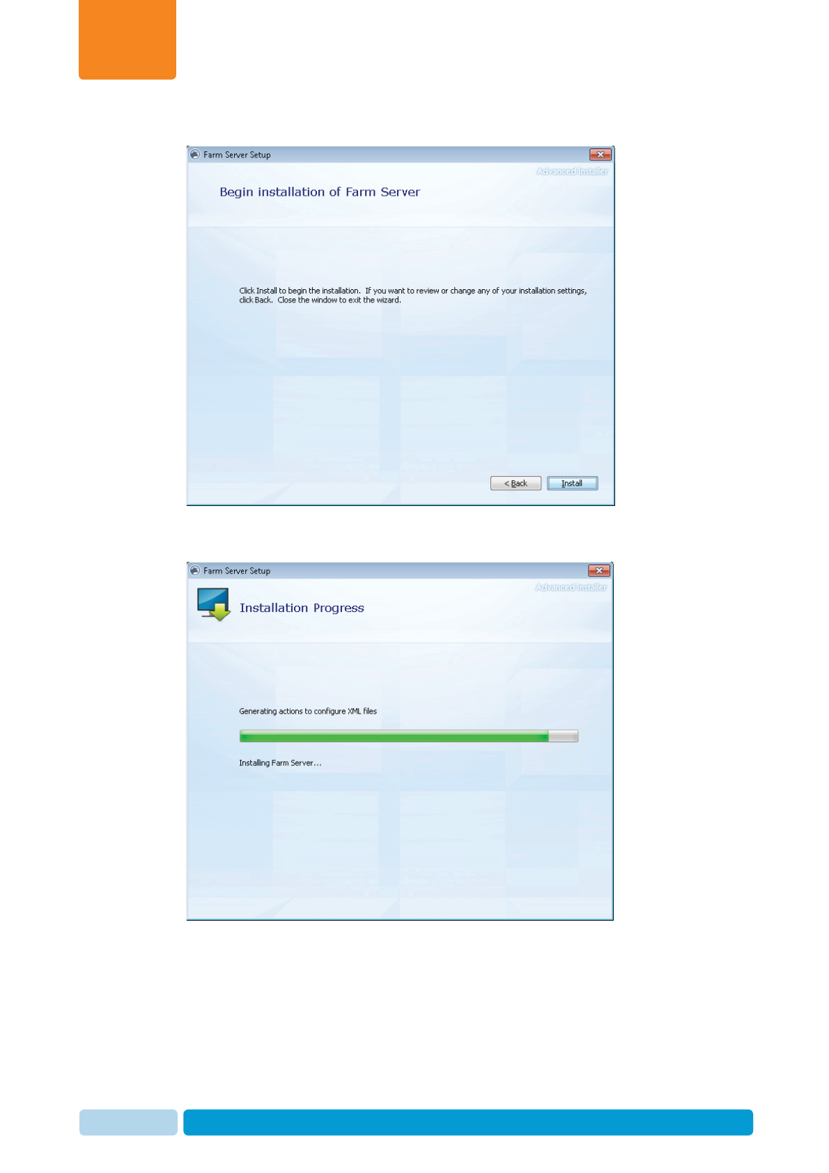
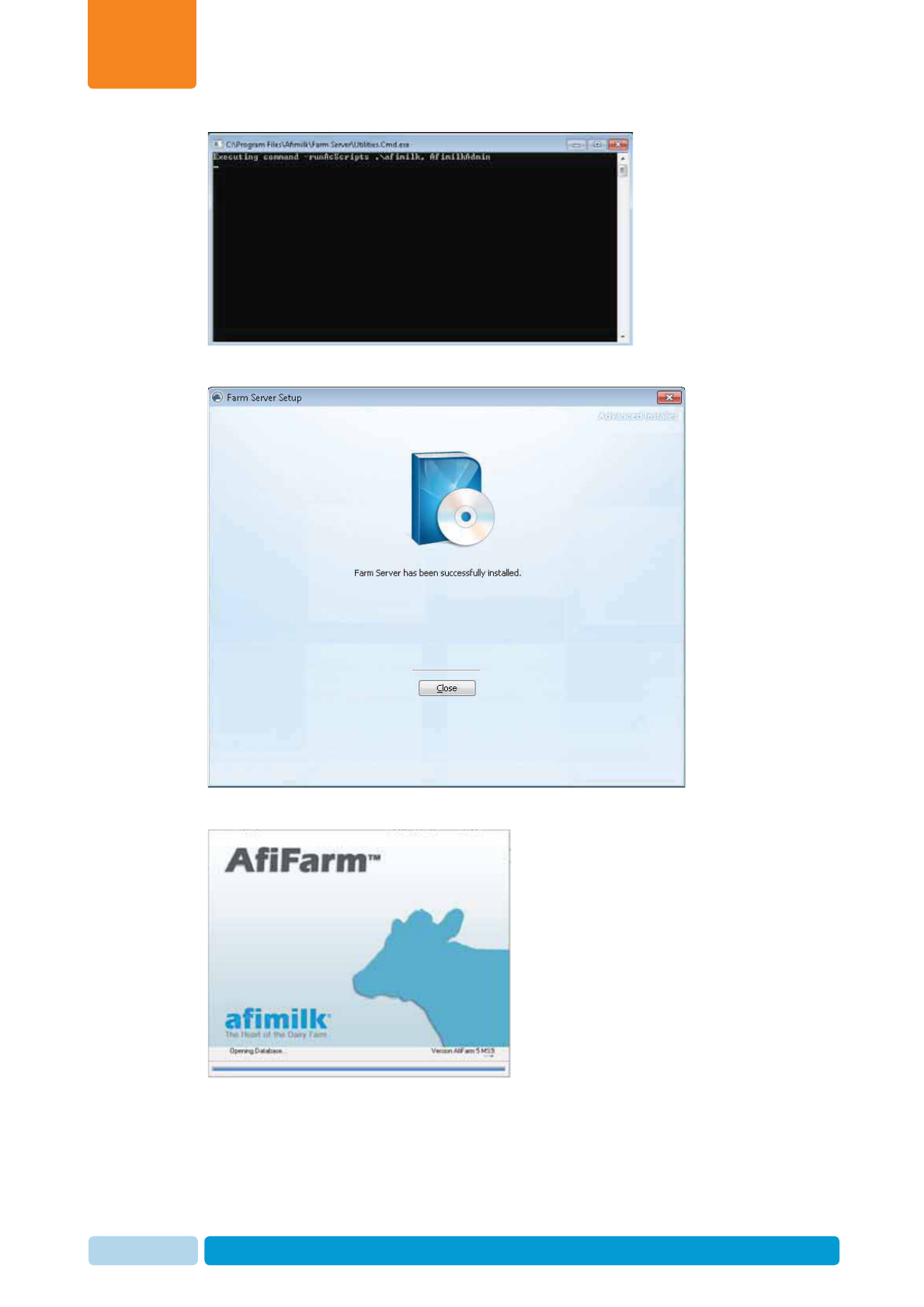
4. The Begin Installation screen appears.
5. Click Install. The automatic installation process starts and the following
progress screens appear. (This may take a few minutes).
Install and Set AfiAct II Software
Chapter
4
Oct 2013 AfiAct II™ Installation Manual65
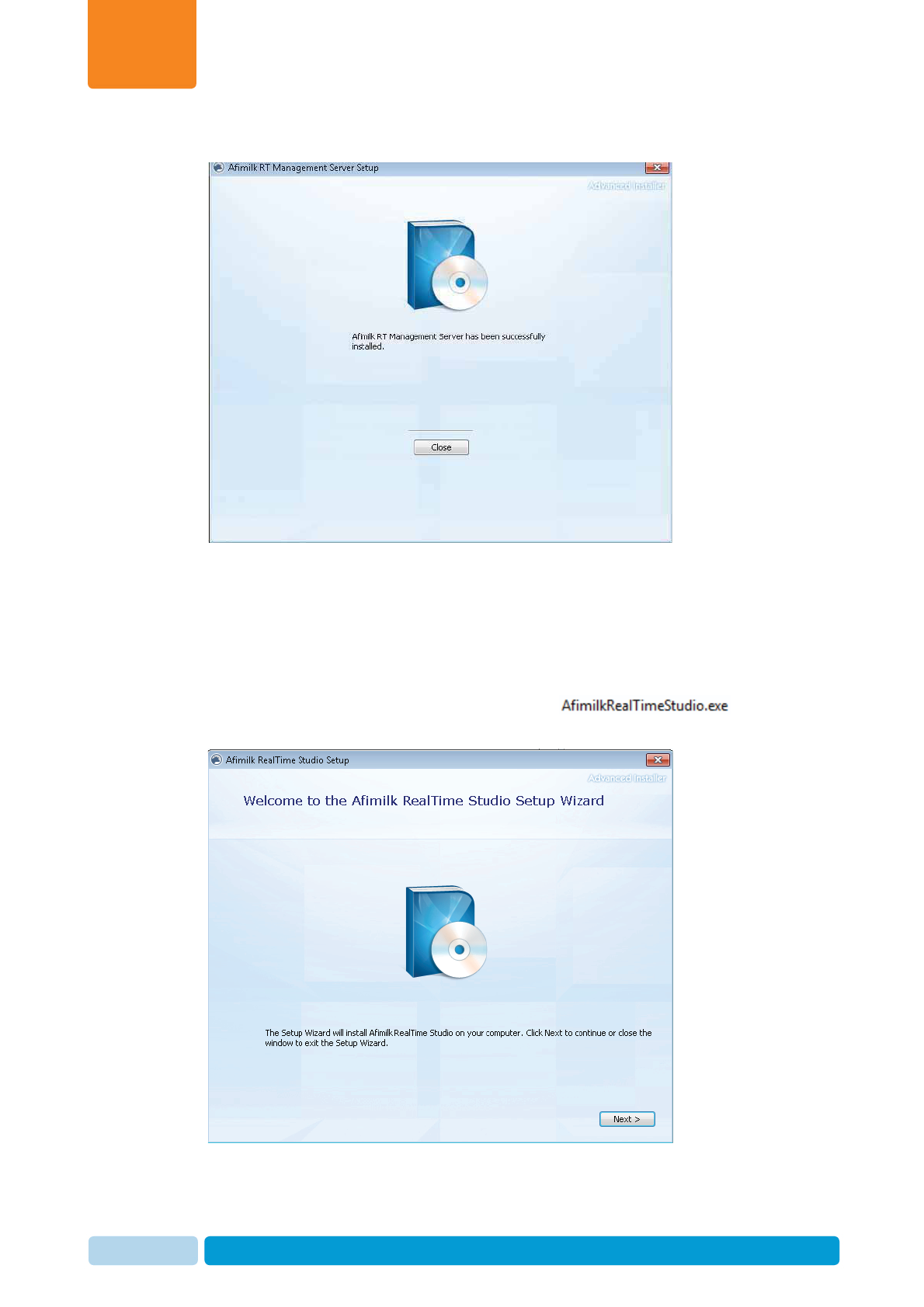
6. When the process ends, the following dialog appears. Click Close.
7. AfiFarm will automatically open
Install and Set AfiAct II Software
Chapter
4
Oct 2013 AfiAct II™ Installation Manual66
8. The server setup installation is complete.
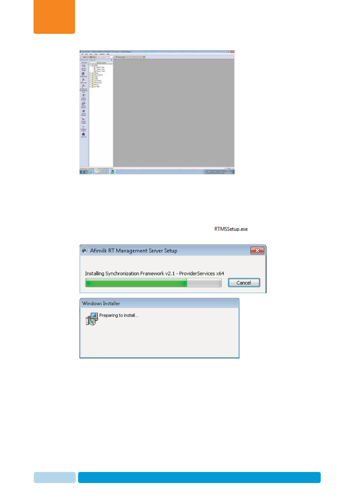
4.2.2 Install the RTMS
After the server setup completes successfully, install the RTMS as follows:
1. Open the AfiFarmRT folder and double click on . The following
pre-installation screens are displayed:
Install and Set AfiAct II Software
Chapter
4
Oct 2013 AfiAct II™ Installation Manual67
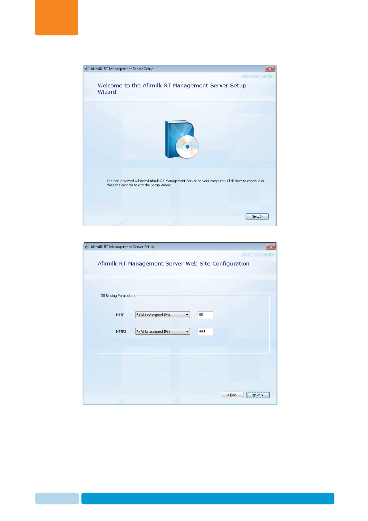
2. The setup wizard welcome screen appears. Click Next.
3. The default web configuration appears. Click Next.
Install and Set AfiAct II Software
Chapter
4
Oct 2013 AfiAct II™ Installation Manual68
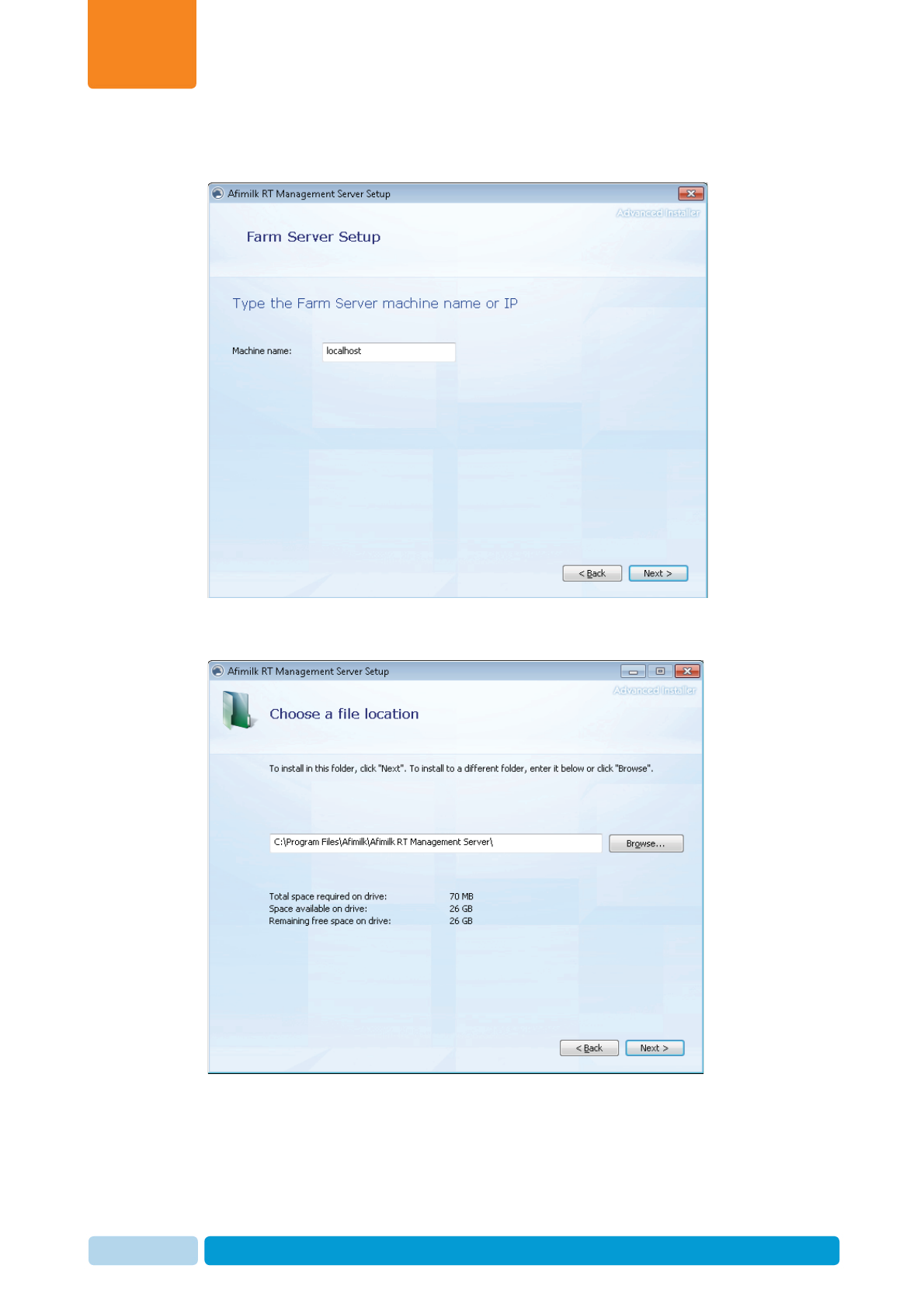
4. The user is requested to enter the server computer location. The default
appears as localhost, as the server is on the current machine. Click Next.
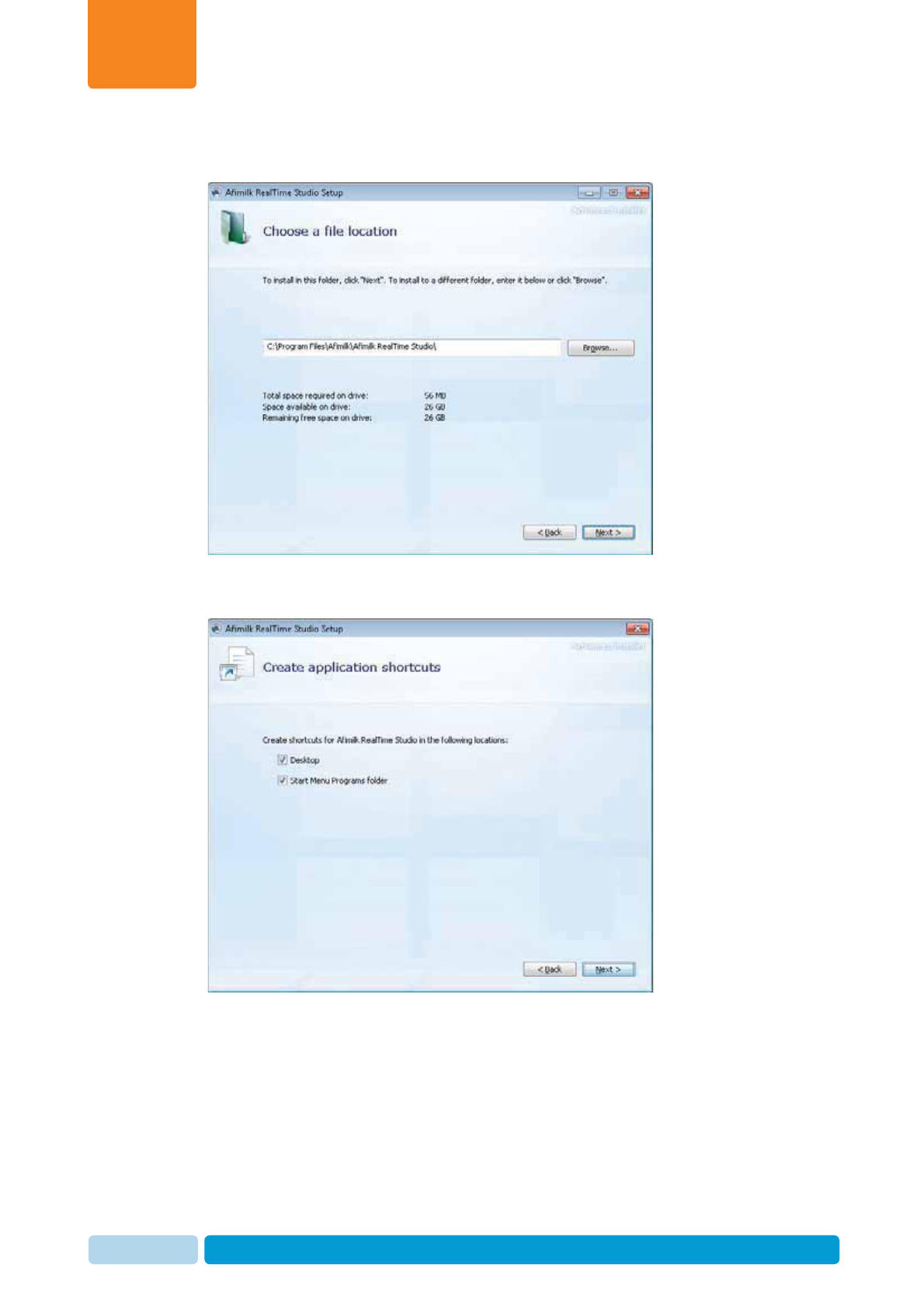
5. Select the location where RTMS files are to be installed. The default appears
automatically. Click Next.

Install and Set AfiAct II Software
Chapter
4
Oct 2013 AfiAct II™ Installation Manual69
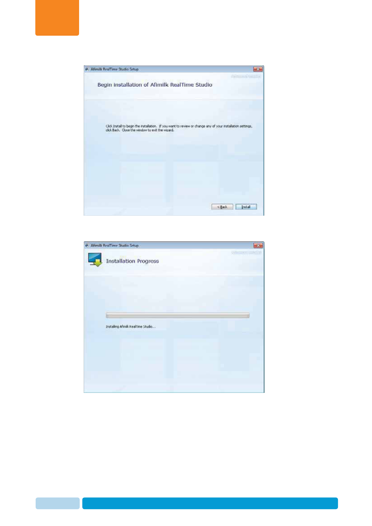
6. The Begin Installation screen appears.
7. Click Install. The automatic installation process starts and the following
progress screens appear. (This may take a few minutes).
Install and Set AfiAct II Software
Chapter
4
Oct 2013 AfiAct II™ Installation Manual70
8. The user is requested to restart the computer. Click Yes.
9. After reboot, the RTMS wizard continues automatically, repeating steps 2-7
above (Note: If the process is not initiated automatically, re-run the process
manually, by double-clicking on the RTMS module again ). Then
the following progress screens appear:
Install and Set AfiAct II Software
Chapter
4
Oct 2013 AfiAct II™ Installation Manual71
10. When the installation is complete, the following screen appears. Click Close.
11. Now the AfiFarm application automatically opens. The RTMS installation is
completed.
4.2.3 Install the RTG Component
After the RTMS installation completes successfully, install the RTG as follows:
1. Open the AfiFarmRT folder and double click on . The
setup wizard welcome screen appears. Click Next.
Install and Set AfiAct II Software
Chapter
4
Oct 2013 AfiAct II™ Installation Manual72
2. Select the location where RTG files are to be installed. The default appears
automatically. Click Next.
3. By default, the wizard generates a shortcut on the desktop and in the start
menu. Click Next.
Install and Set AfiAct II Software
Chapter
4
Oct 2013 AfiAct II™ Installation Manual73
4. The Begin Installation screen appears.
5. Click Install. The automatic installation process starts and the following
progress screens appear. (This may take a few minutes).
Install and Set AfiAct II Software
Chapter
4
Oct 2013 AfiAct II™ Installation Manual74
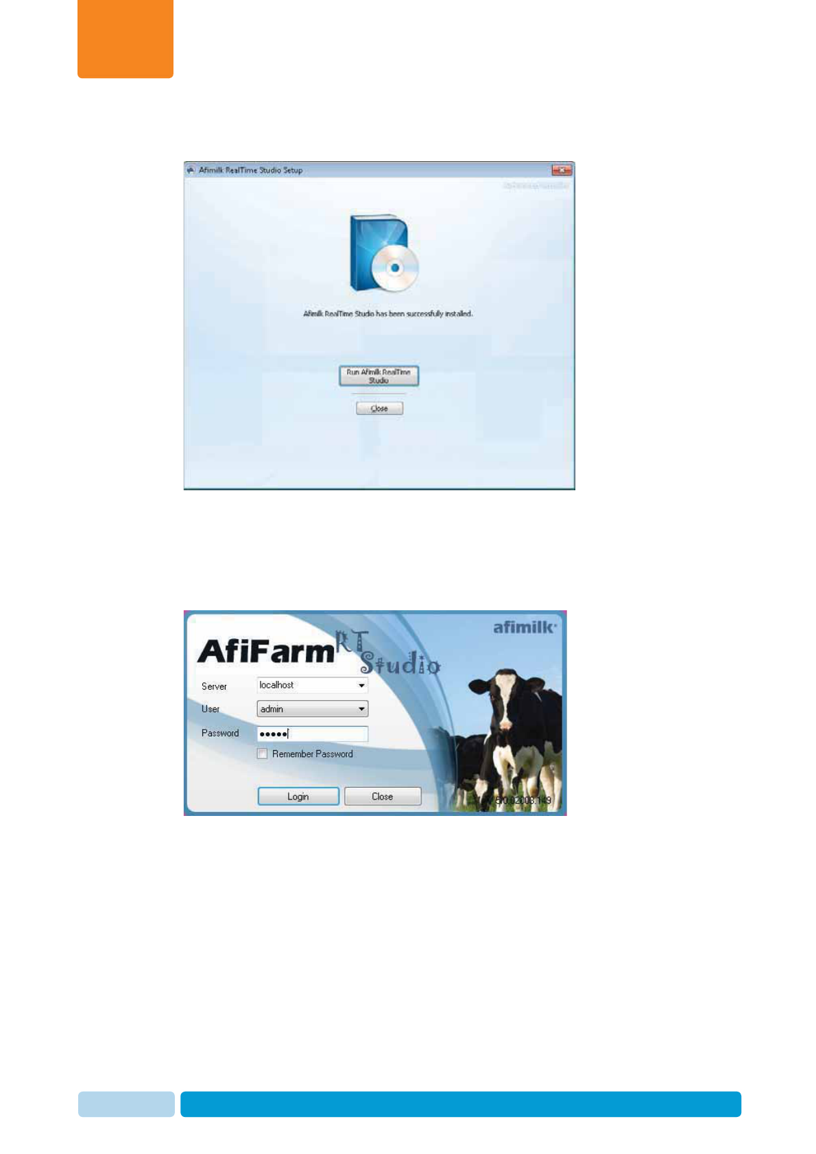
6. When the installation is done, the following screen appears. Click Run afimilk
RealTime Studio.
7. The login screen appears. Enter the following attributes:
xServer:localhost
xUser:admin
xPassword:admin
Install and Set AfiAct II Software
Chapter
4
Oct 2013 AfiAct II™ Installation Manual75
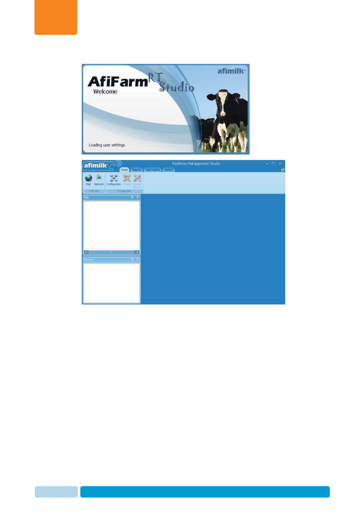
8. Click Login. The Real Time GUI opens.
Install and Set AfiAct II Software
Chapter
4
Oct 2013 AfiAct II™ Installation Manual76
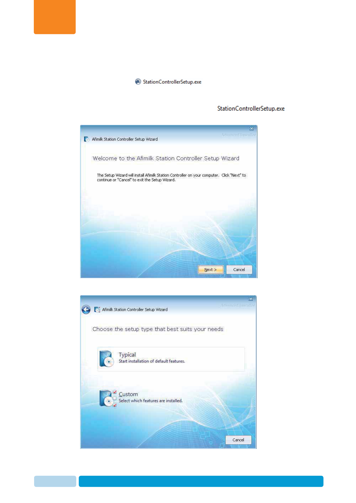
4.2.4 Install the RT Station Controller Component
After installing the RTMS, the final RT module is installed: the RT Station Controller
Setup RTC module: .
To install the RT Station Controller Setup RTC
1. Open the AfiFarmRT folder and double click on . The
setup wizard welcome screen appears. Click Next.
2. Select Typical for a standard configuration. Click Next.
Install and Set AfiAct II Software
Chapter
4
Oct 2013 AfiAct II™ Installation Manual77
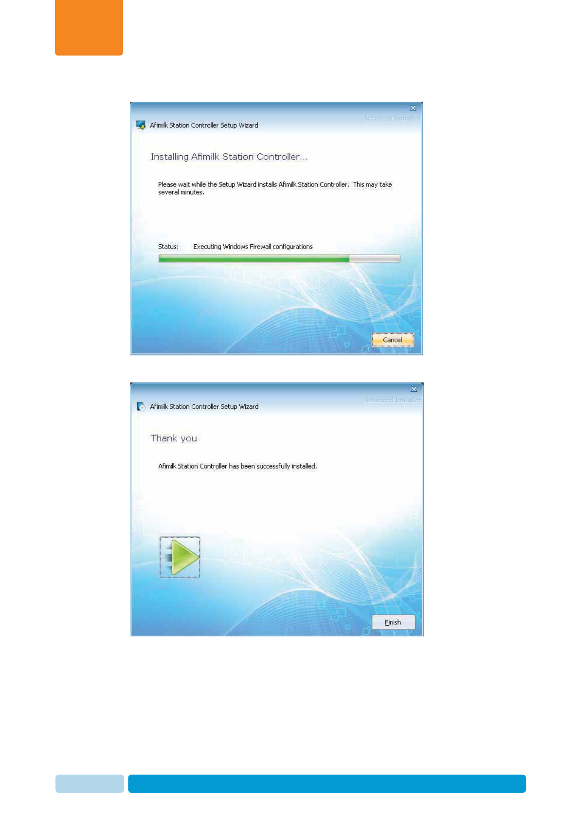
3. The controller installation starts, showing a progress bar.
4. When the installation is done, the following screen appears. Click Finish.

Install and Set AfiAct II Software
Chapter
4
Oct 2013 AfiAct II™ Installation Manual78
4.3 Set the RT System (Quick Start)
AfiAct II components are connected via the network (wired or wireless), where the
AfiFarm RT System manages the communication between the components (AfiAct
II software, Reader, etc.).
The AfiFarm RT system client-server architecture involves three types of computer
functions, all running on the same PC for AfiAct II:Server (manages herd database,
system configuration and licensing); Controller (manages the real-time processes,
and includes a small database to control the stations and collect data when the
communication with the server is interrupted), Client (for user access to herd data).
To allow basic system functionality and overall system communication, the following
basic parameters must be set in the AfiFarm RT System for quick-start:
xHW system layout: PCs, devices (e.g. Reader(s) Unique ID), adaptors, ports,
etc.)
xLogical system definitions, reflecting the stations (i.e. AfiAct, AfiSort, milking-
parlors,…), sites (aggregation of all the stations with the same identification
system – usually geographically close to each other), tracks (monitored animals;
heifers/milking cows) and required sampling sessions.
x Deployment of the software to support the previously defined site(s) (in this
case: AfiAct II) via the tray configurator.
The following sections provide an overview of the RT System navigation, session-
definition requirements, and explain how to set up the mandatory system fields via
the AfiFarm RT System.
NOTE
The AfiFarm RT system is a powerful tool, allowing the technician to perform
Reader settings, tags identified by the system, view map of connected
network elements, station reports, etc. For a summary on the AfiFarm RT
System capabilities refer to Appendix C.
NOTE
The setup done via the RT System interface is checked at a later stage, when
the whole system is connected (including the Reader, see 5.2).
NOTENOTE
For better system monitoring, it is recommended to define a user report that
detects tags not assigned to animals), see Appendix C.
Install and Set AfiAct II Software
Chapter
4
Oct 2013 AfiAct II™ Installation Manual79
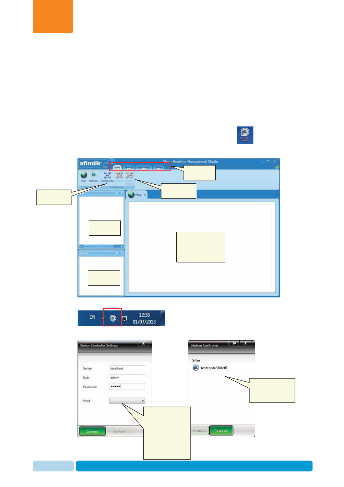
4.3.1 Navigating the RT System
The RT system includes two accessible GUI elements:
xThe RT Studio screens – for configuring the system, managing reports, etc.
xThe Station Controller screens – used for:
x Deployment of the specific-site-type supporting software (here: AfiAct II)
x Monitoring connections with the defined system sites
The RT Studio Screens are accessed via the AfiFarm RT icon , and include
the following areas (see Appendix C for details)
The Station Controller screens are accessed from the icon in the system tray
and displays the monitoring screen (connected
sites) and the configuration screen (connecting to server host)
Ribbon control
tabs
Corresponding
sub-options
Network map
window
Network
window
Main display:
selected report,
configuration
parameters, etc.
Monitoring
screen:
Connected sites
Configuration
screen: Selecting
host (i.e.
previously defined
site type) for
corresponding SW
deployment
System
configuration

Install and Set AfiAct II Software
Chapter
4
Oct 2013 AfiAct II™ Installation Manual80
4.3.2 Determine the Required Sampling Sessions
To allow AfiAct II algorithms to analyze the data correctly, the system must be set to
reflect the specific farm monitoring needs. These are set by the following
parameters:
xTracks –Tracks determine the type of animals that are monitored: heifers/cows.
xStations – Stations determine the specific monitored activity: milking, AfiAct II,
AfiSort, etc.
xSites – The group of stations in the same geographical area, using the same
identification system
xSessions – The sessions are set to reflect the specific farm’s daily scheduled
activities. (E.g. milking times, breeding times, pasture times, feeding times, and
other activities done in the farm).
To determine the above parameters correctly, the dealer personnel together with the
farmer must collect and consider the relevant information. The following items
provide guidelines for determining the farm’s sessions via the RT System. Fine
tuning may be done after running the system for a test period.
To determine the sessions, refer to the following criteria and guidelines
1. Tracks reflect the specific animals monitored (milking cows / heifers / both).
Check what types of animals will be carrying tags.
2. Check when breeding is done during the day.
3. Session times are set according to the tracked animal as follows:
xFor milking cows: the session times are set based on milking times:
x Check what are the milking times (i.e. when is the first group brought
to the milking parlor; when does the last cow leave the milking parlor)
x Start the session 1-1.5 hours before each milking time, and at least one
hour after the preceding milking. If the gap time between milking is not
long enough, configure the beginning time of the sessions to 1/2 an
hour after the last cow of the preceding milking leaves the parlor.
xFor heifers: Configure one session of 24 hours.
Check the heifers’ data after 3-4 days. If there is very high activity during
part of the day – configure two sessions: one for the high activity and one
for lower activity. Configure the high activity session for 1.5 hours before the
high activity occurs, and up to 1.5 hours after the high activity occurs.
4. The recommended number of sessions per day is between 1 and 3.
5. The session times must be continuous, ensuring 24 hours coverage
NOTE
If the session intervals or schedules are changed, contact afimilk
representative to re-configure the system.
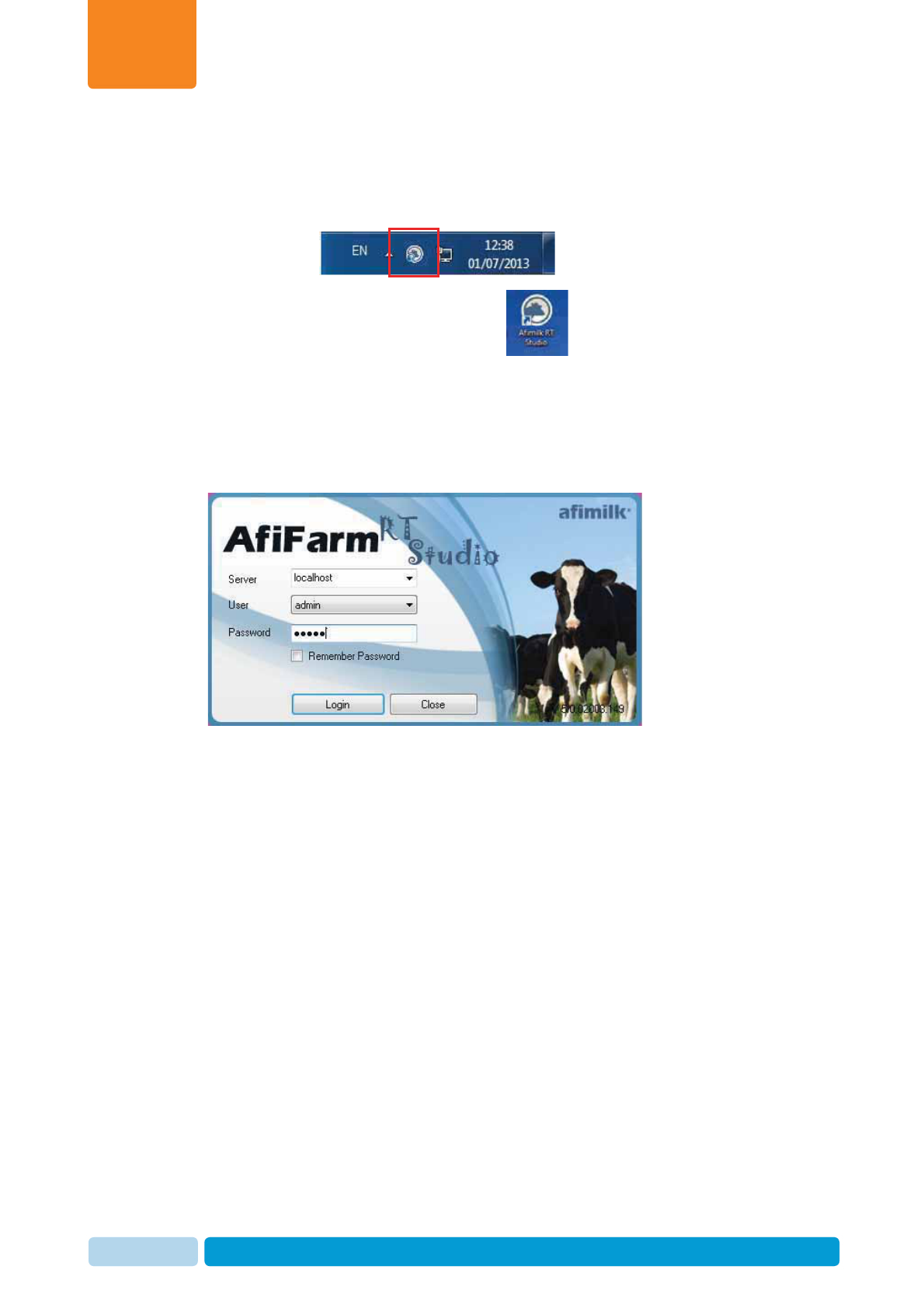
Install and Set AfiAct II Software
Chapter
4
Oct 2013 AfiAct II™ Installation Manual81
4.3.3 Set System Mandatory Parameters
To define the system computers (server and system controller)
1. Verify that the Station Controller is up and running by checking the icon in the
system tray
2. Open the AfiFarm RT system (click the icon).
3. The login screen appears. Enter the following login attributes:
xServer:localhost
xUser:admin
xPassword:admin
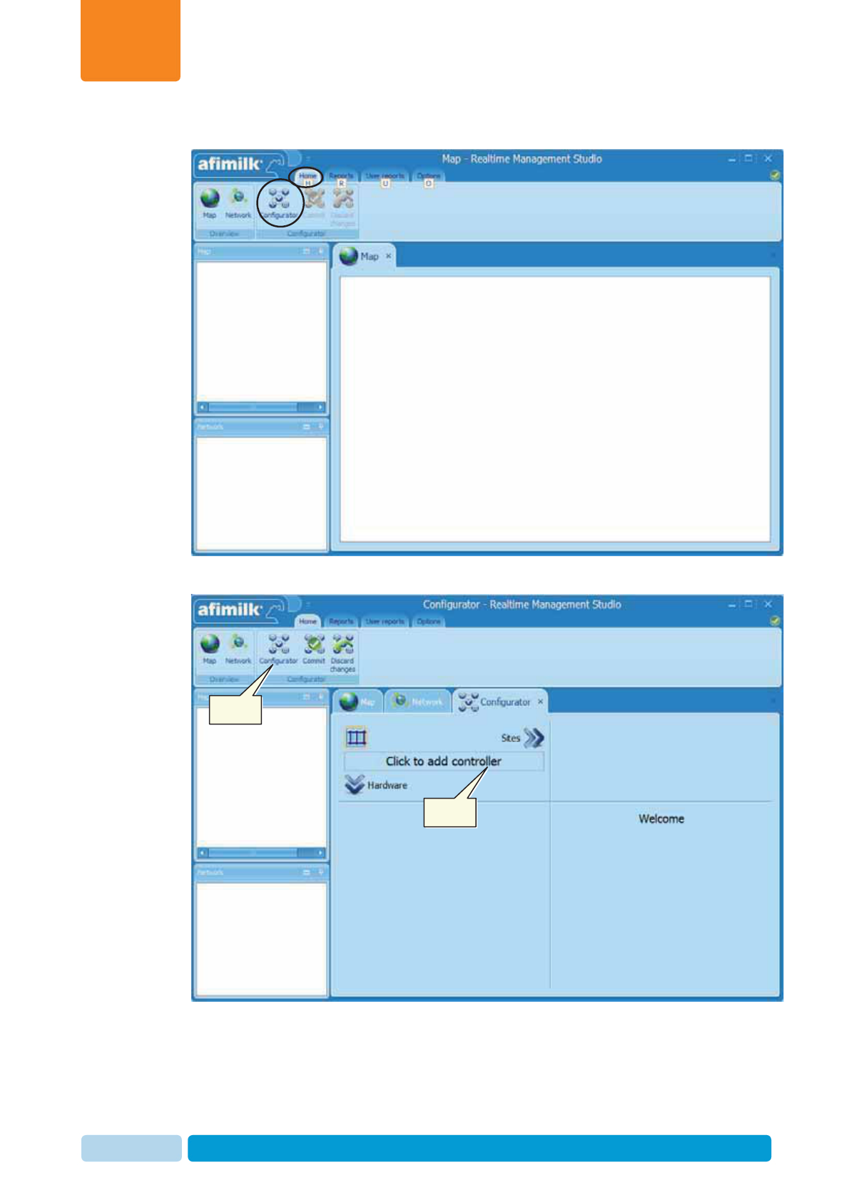
Install and Set AfiAct II Software
Chapter
4
Oct 2013 AfiAct II™ Installation Manual82
4. Click Login. The RT main screen appears.
5. Under the Home tab, select Configurator from the tab sub-options.
Select
Click
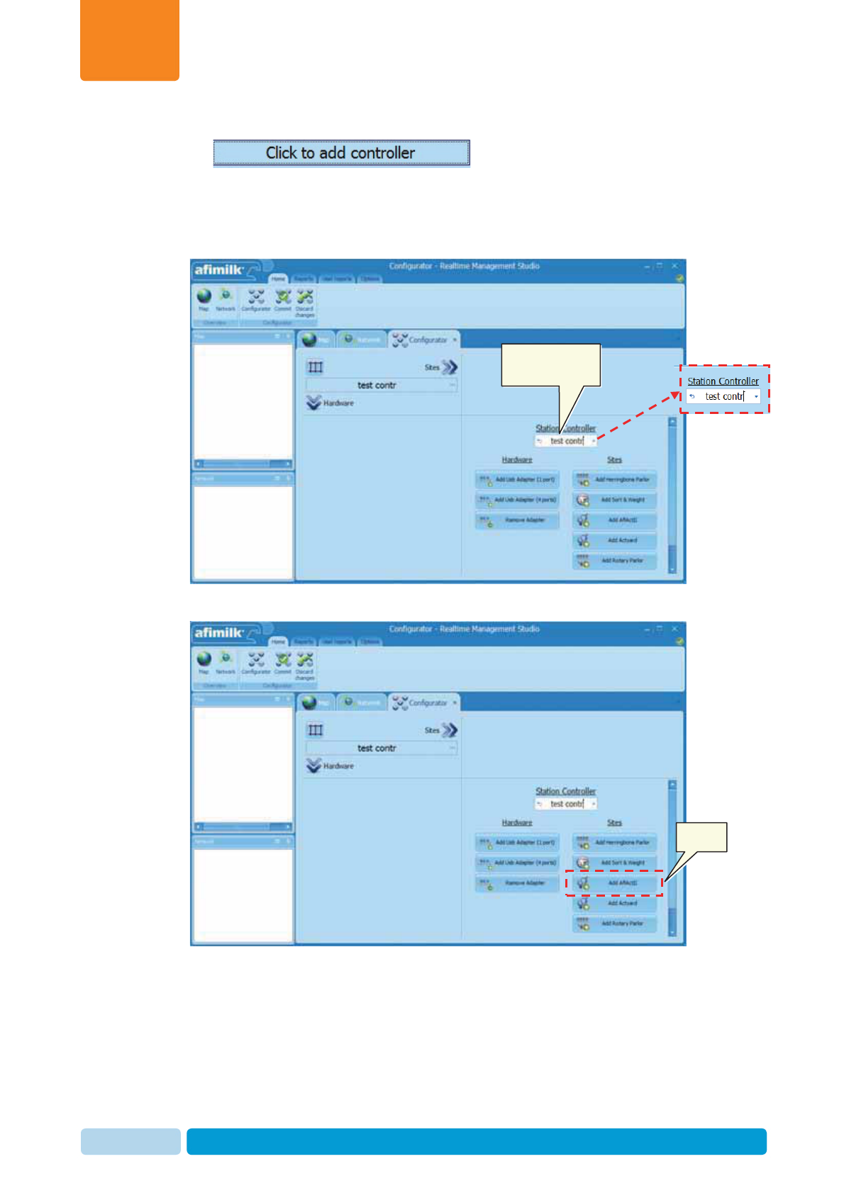
Install and Set AfiAct II Software
Chapter
4
Oct 2013 AfiAct II™ Installation Manual83
6. To determine the controller used click on the “Click to Add controller”
To define the new AfiAct II site
7. In the New Controller screen enter a meaningful name for the controller (in the
following example: test contr), then choose Add AfiAct II from the Sites
8. Add an AfiAct II site: Choose Add AfiAct II from the sites menu
Enter a
meaningful name
Choose
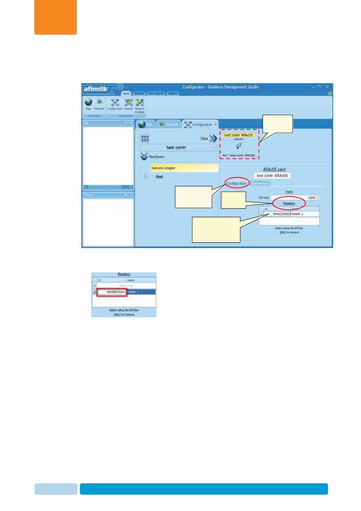
Install and Set AfiAct II Software
Chapter
4
Oct 2013 AfiAct II™ Installation Manual84
Set the Reader(s) and Ports
9. Click the Configuration sub-tab. The relevant TCP port is set to the default
value.
10. In the Readers area, enter the Reader UID (as obtained from the label on the
Reader, see 1.3.4). Then enter a Reader name. Example:
Note: If the system includes more than a single Reader, enter all of the Reader’s
UIDs and names.
AfiAct II site
added
Click
Configuration
sub-tab
Enter reader ID (as
appears on the
reader’s label)
Readers
area
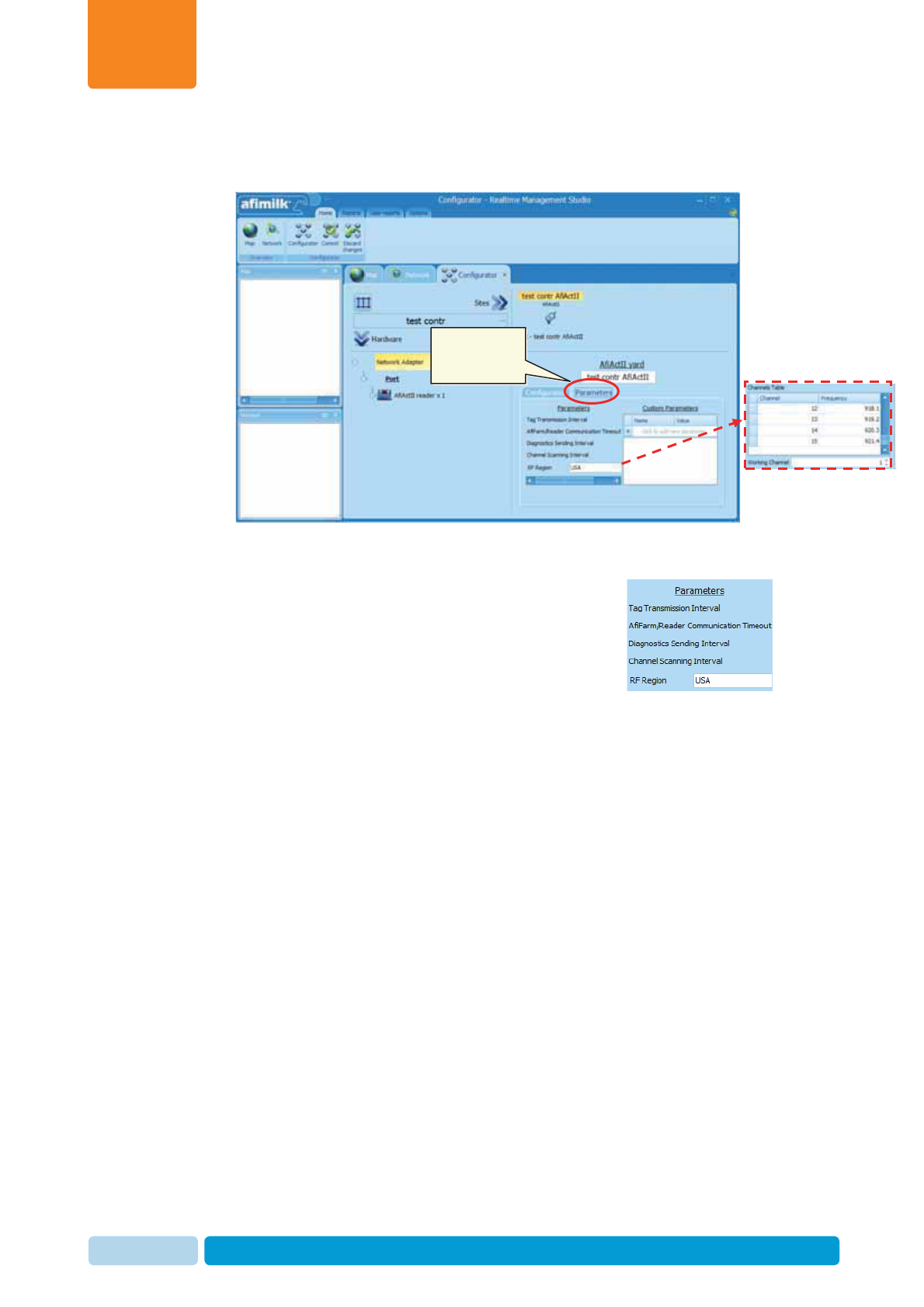
Install and Set AfiAct II Software
Chapter
4
Oct 2013 AfiAct II™ Installation Manual85
Set the relevant parameters
11. To enter the relevant parameters, click on the Parameters sub tab
The following parameters are available:
xTag transmission interval - sets the interval in
which the tags send their data to the Reader
(default 15)
xAfiFarm/Reader Communication Timeout – not
to be changed (default 3)
xDiagnosis Sending Interval – not to be changed
(default 60)
xChannel Scanning Interval – not to be changed
(default 60)
xRF Region – Determines the transmission region
with its relevant frequency range. When clicked – a
corresponding frequency channel table opens,
allowing the user to select a different channel (in
case of interferences). (Default is set according to
your region (e.g. USA); your tags are factory-set to
the same default channels as the Reader).
Click
Parameters
sub-tab
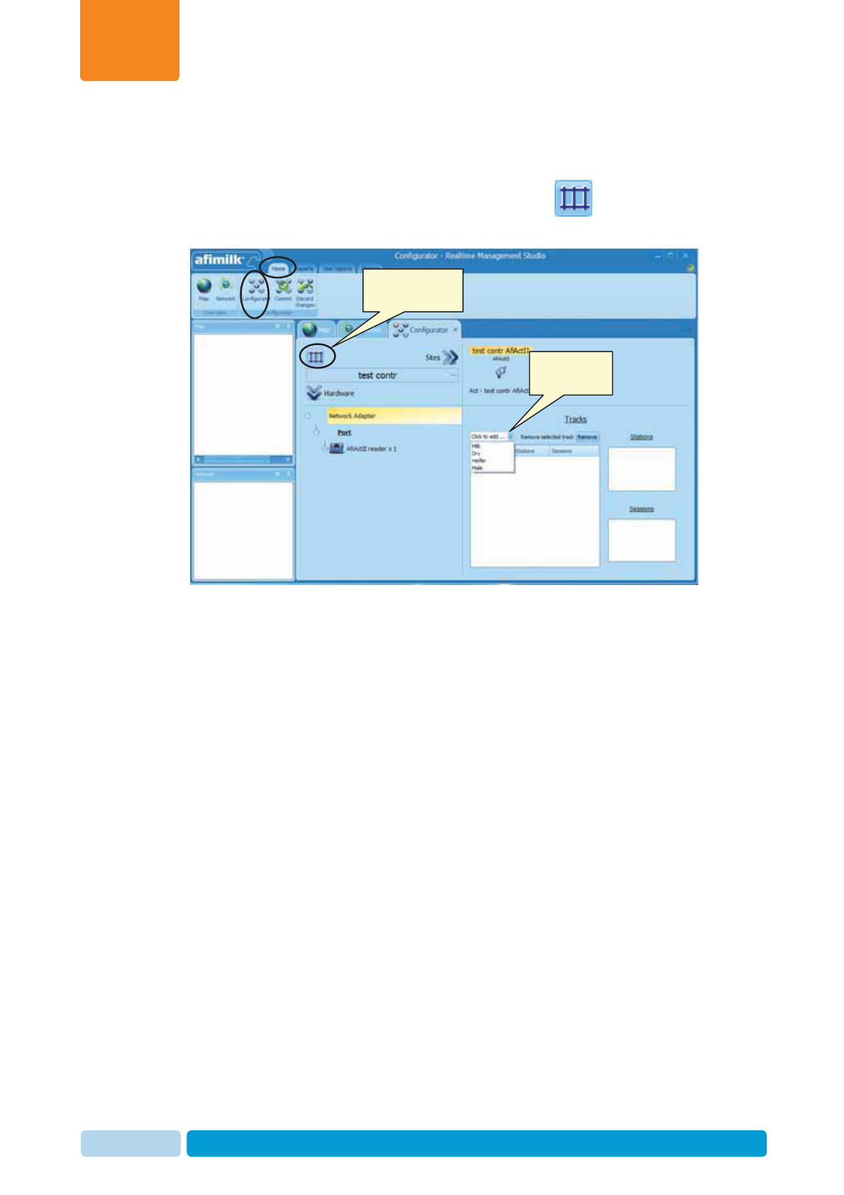
Install and Set AfiAct II Software
Chapter
4
Oct 2013 AfiAct II™ Installation Manual86
12. Select your RF Region and relevant working channel
Set a track with stations and their sessions
13. Under the Home ÆConfigurator tab, click the Track button, and select
the type of track to be defined (Milk cows or Heifers).
14. The displayed screen shows the following main areas:
x Track management area
x Station definition area
x Sessions definition area
Enter a meaningful name to the track
Click to set track
& sessions
Choose track
type
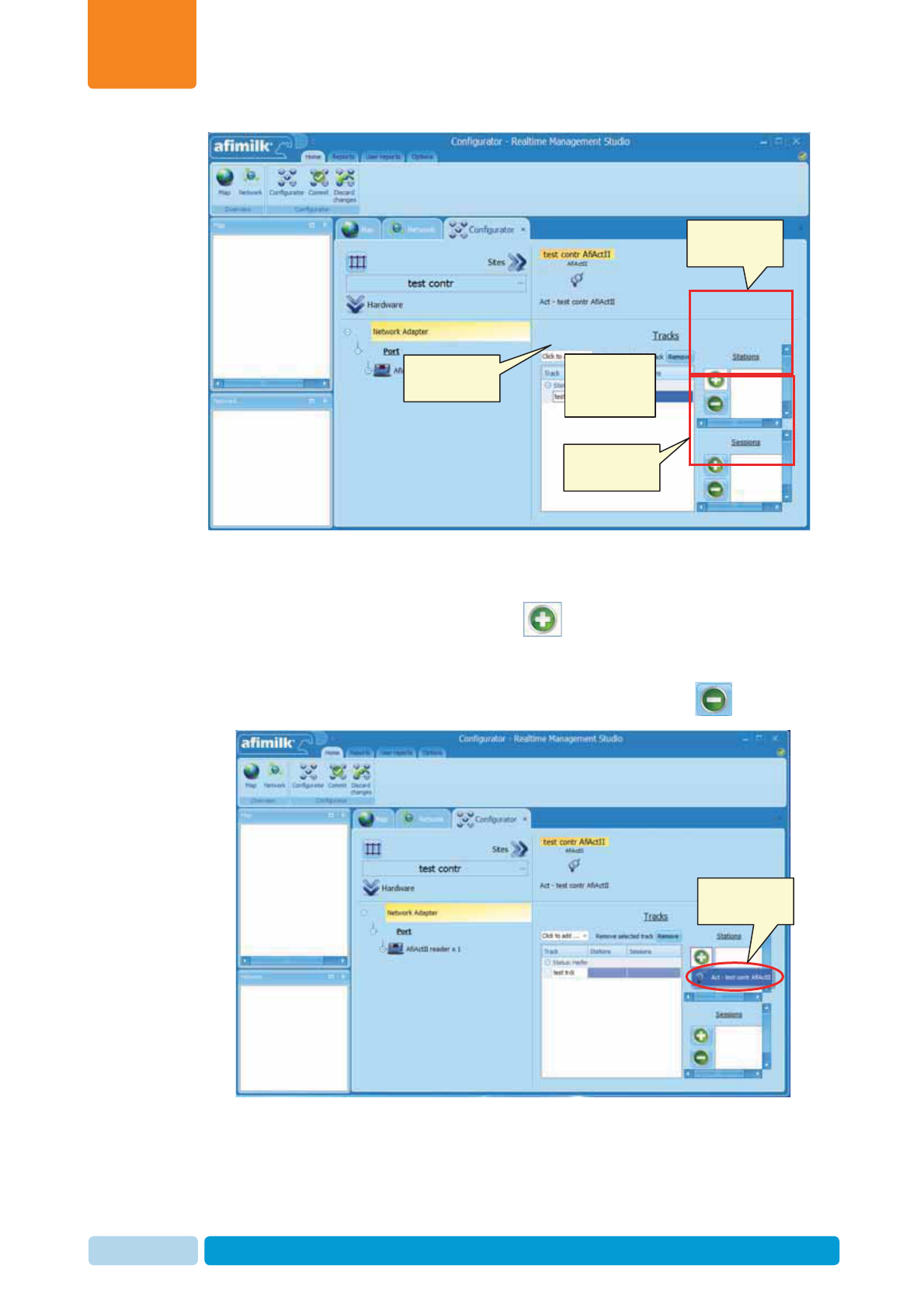
Install and Set AfiAct II Software
Chapter
4
Oct 2013 AfiAct II™ Installation Manual87
15. Add the AfiAct II station to your track, as follows:
x In the station definition area, click the sign.
x Choose the Act station from the roll-down list
Note: To remove a station, select the required station and click the sign
Track
management
area
Station
definition area
Session
definition area
Name the
Track
Choose the Act
station
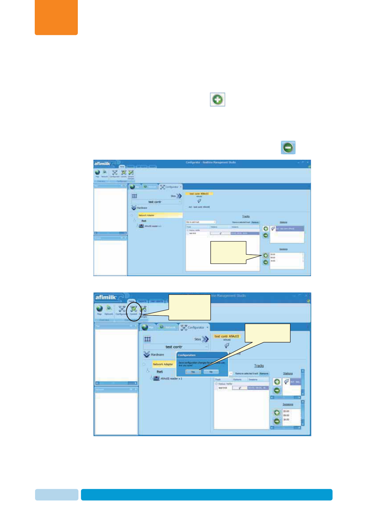
Install and Set AfiAct II Software
Chapter
4
Oct 2013 AfiAct II™ Installation Manual88
16. Define sessions for each defined track’s station, corresponding to the farm
schedule (Heifers will usually require only one or two sessions) as follows:
x In the station definition area, select the station to be updated (in this
example: Act on Test contrl).
x In the session definition area, click the sign to add a session. Repeat
this to add the required number of sessions (in the following example: 3)
x If the sessions are not distributed evenly during the 24 hours: For each
session, select the time in which the session starts.
Note: To remove a session, select the required session and click the sign
17. When done updating, click Commit. A confirmation window appears.
18. Click Yes to approve changes, Then wait a few seconds while AfiFarm restarts,
and until all the processes are up and running.
When done,
click to commit
changes
Click to add a
session for
the station
Click to confirm
changes
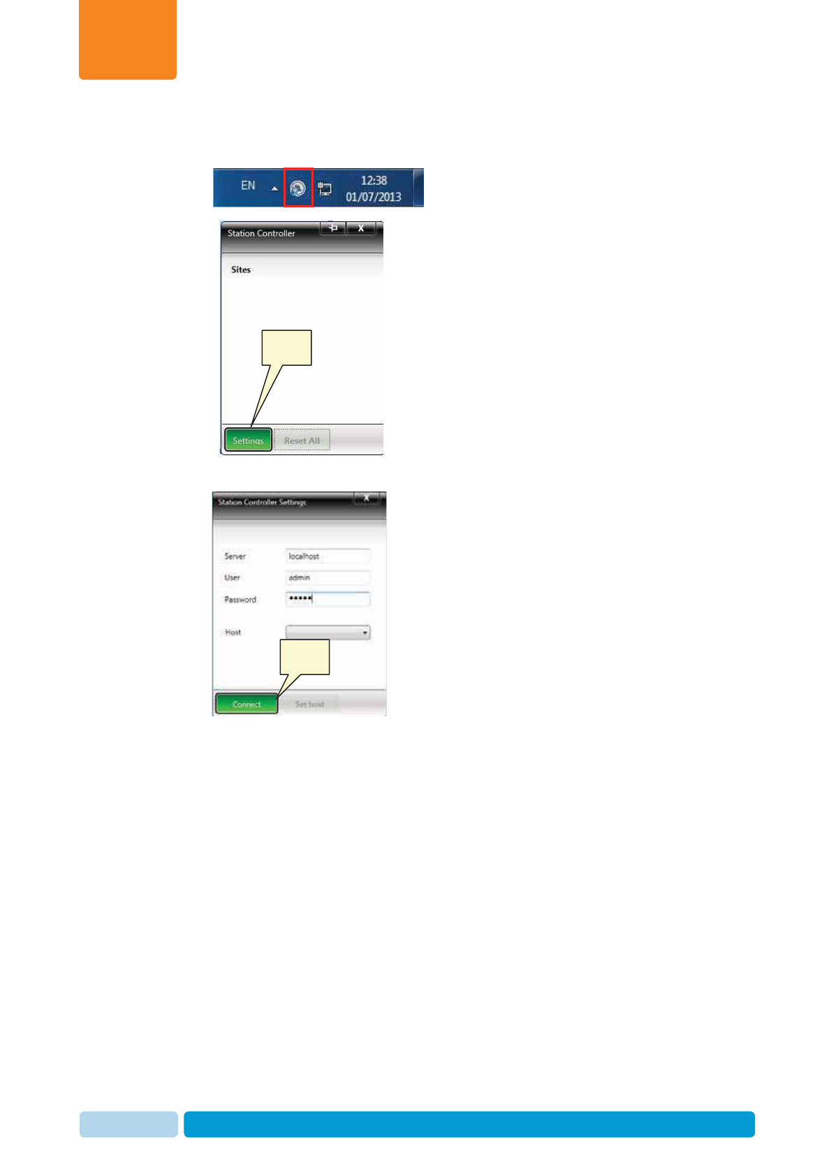
Install and Set AfiAct II Software
Chapter
4
Oct 2013 AfiAct II™ Installation Manual89
Deployment of the software according to the defined station (i.e. AfiAct)
19. Open the Station Controller manager by clicking the icon in the system tray
. The following dialog appears
20. Click settings. The following Station Controller Settings dialog appears
21. Enter the following attributes:
x Server: localhost
x User: admin
x Password: admin
Click the connect button.
Click
Click
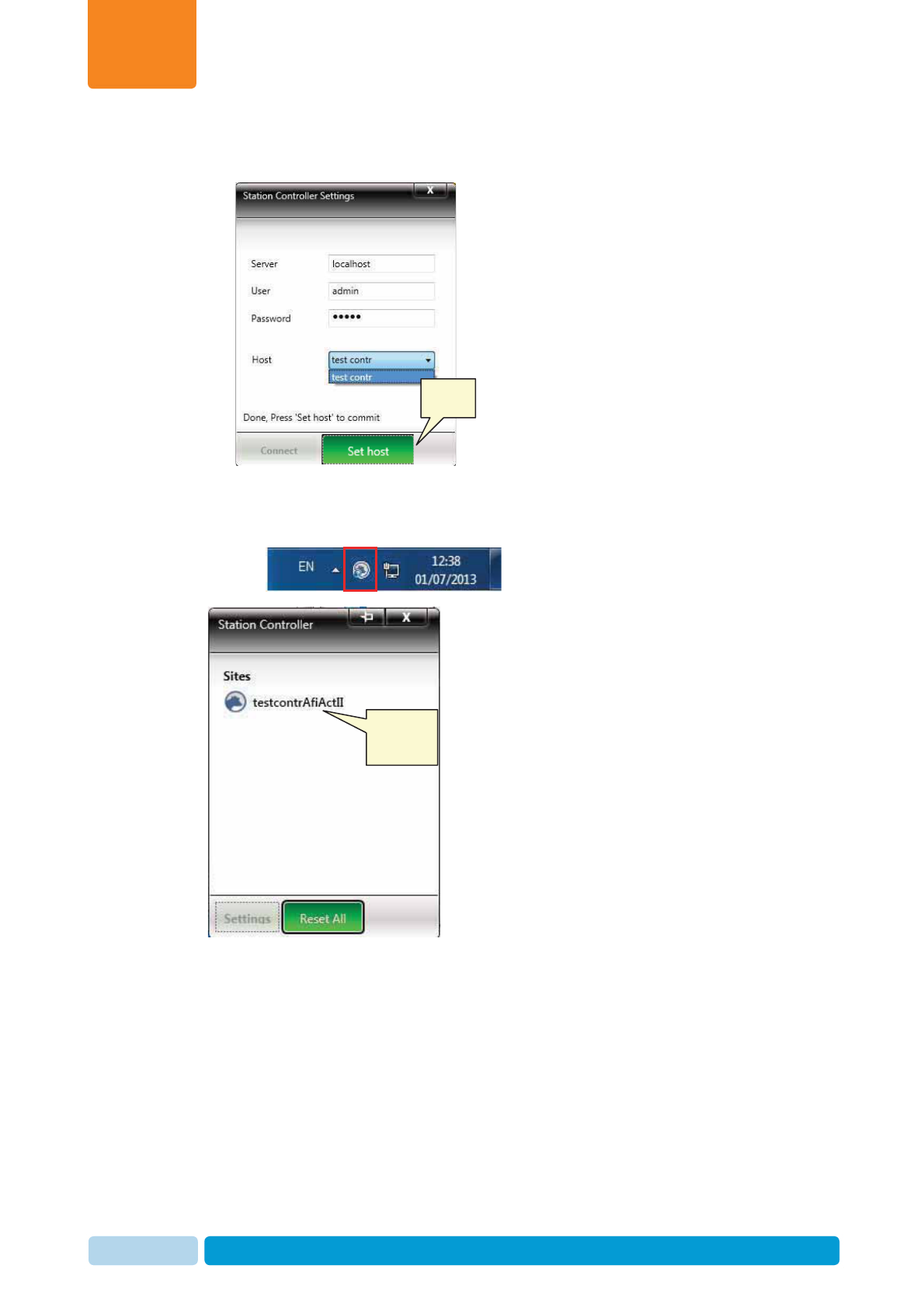
Install and Set AfiAct II Software
Chapter
4
Oct 2013 AfiAct II™ Installation Manual90
22. In the updated dialog, from the available list of hosts (i.e. computers with
defined controllers), select the desired Host (in this example: test contrl).
23. Click the Set host button. The software configuration corresponding to the
selected-defined track-station is now installed. Close the above settings window.
24. Open the Station Controller manager again by clicking the icon in the system
tray . The following dialog appears
25. You will now be able to monitor the software that manages the defined Reader.
(If the defined controller is not displayed, you may click Reset All).
Note: after configuring the station controller, when connecting the Reader (see 5),
the Reader’s PC comm. LED should indicate communication between the Reader
and PC.
Click
Defined &
connected
site

Install and Set AfiAct II Software
Chapter
4
Oct 2013 AfiAct II™ Installation Manual91
4.3.4 Additional RT Configurations and Monitoring
For better system monitoring, it is recommended to perform some basic settings:
x Define a user report for detecting unassigned tags.
x Verify that the newly defined site appears as an icon in the icon’s tab. (Click on
the site icon, and verify that it is connected; if the site is connected: the Reader
name and IP_Address will be displayed).
x Check the list of faulty tags.
x Customize the system to your specific farm.
These setups may be fine-tuned or updated at any time after mounting the Reader.
For details on system configurations and maintenance via the RT System, refer to
Appendix C.
NOTE
Before the system may be used for detecting cows in heat, average behavior
performance baseline should be generated by the application. This can take 5
to 6 days
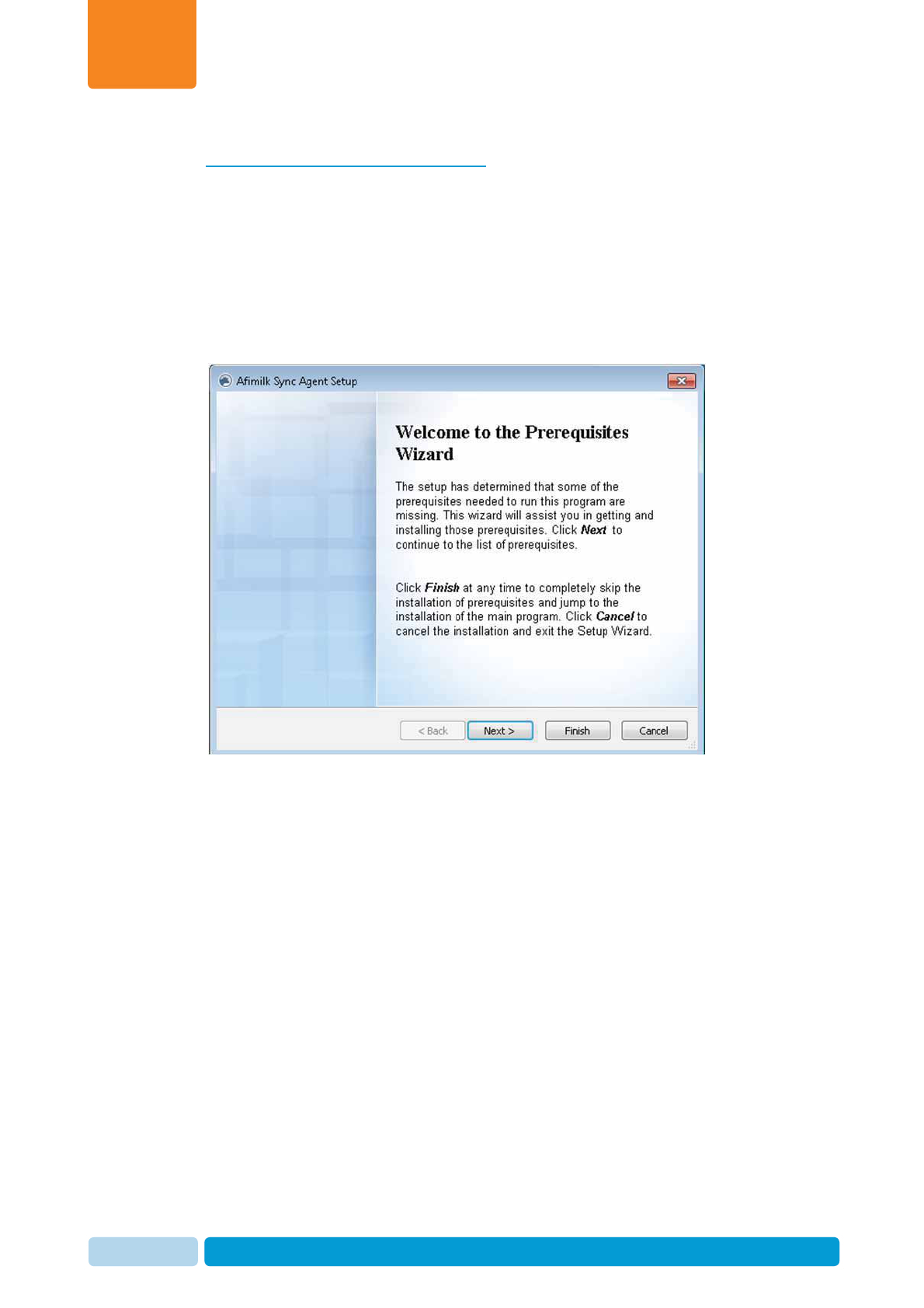
Install and Set AfiAct II Software
Chapter
4
Oct 2013 AfiAct II™ Installation Manual92
4.4 In Integrated Systems: Install the Sync Agent
In integrated mode with AfiFarm systems, where existing AfiFarm 4 software is
already installed, install the Sync agent on the AfiFarm 4 computer. (The installation
time is about 2-5 minutes).
To install the sync agent:
1. Open the AfiFarm folder (in the provided software CD) and double click on
SyncAgentSetup.exe. The setup wizard Prerequisites welcome screen appears.
Click Next.
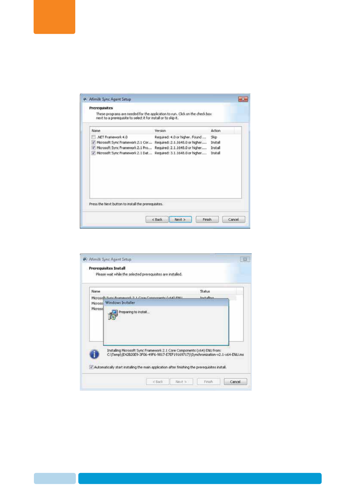
Install and Set AfiAct II Software
Chapter
4
Oct 2013 AfiAct II™ Installation Manual93
2. The default list of prerequisite programs that will be installed appears.
Note: To change the default, you may uncheck the box near the element not to
be installed. However, this is not recommended.
Click Next.
3. The following messages appear while the checked items are now being
installed. This may take a few minutes.
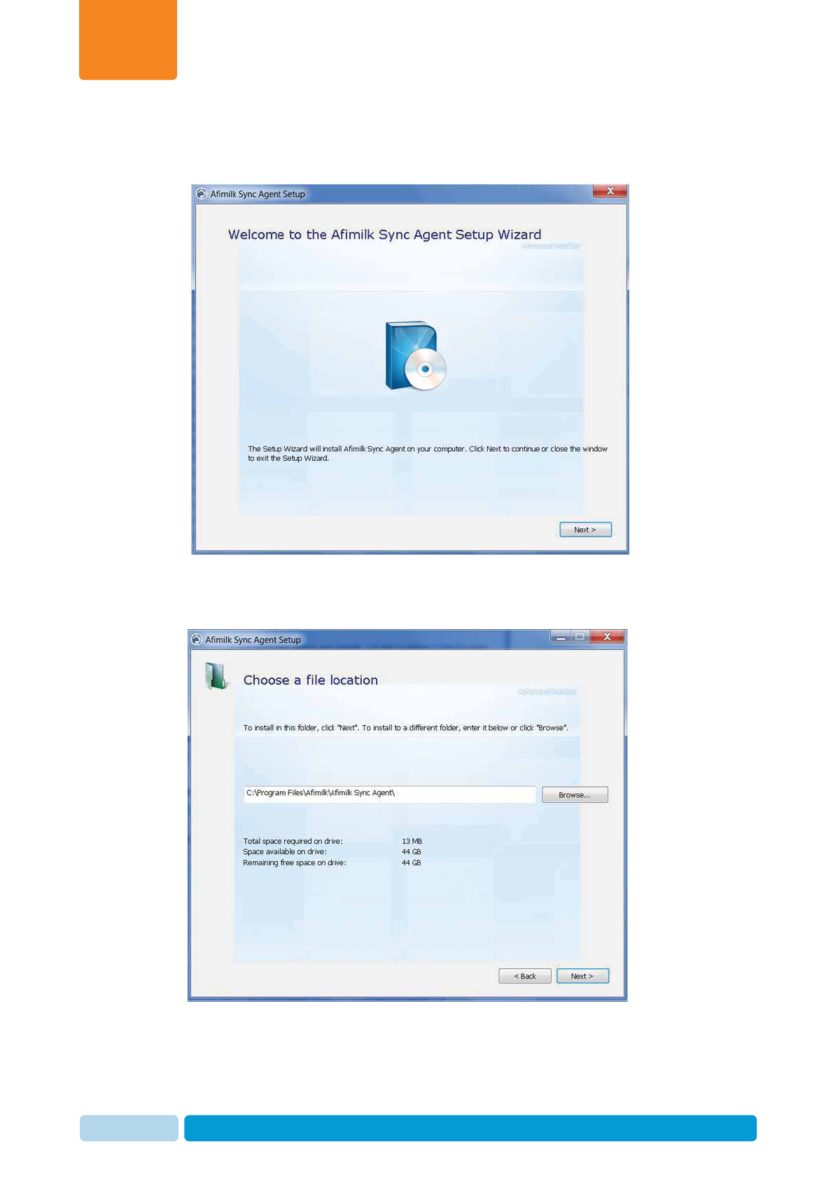
Install and Set AfiAct II Software
Chapter
4
Oct 2013 AfiAct II™ Installation Manual94
4. When the pre-requisite installation is complete, the Next button becomes
available. Click Next to start the Sync setup. The Sync Agent Setup Welcome
screen appears.
5. Click Next. The Choose file location dialog appears, displaying the default path
where the sync files will be located. To change the default you may either type a
different path or click the Browse button to navigate to your desired location.
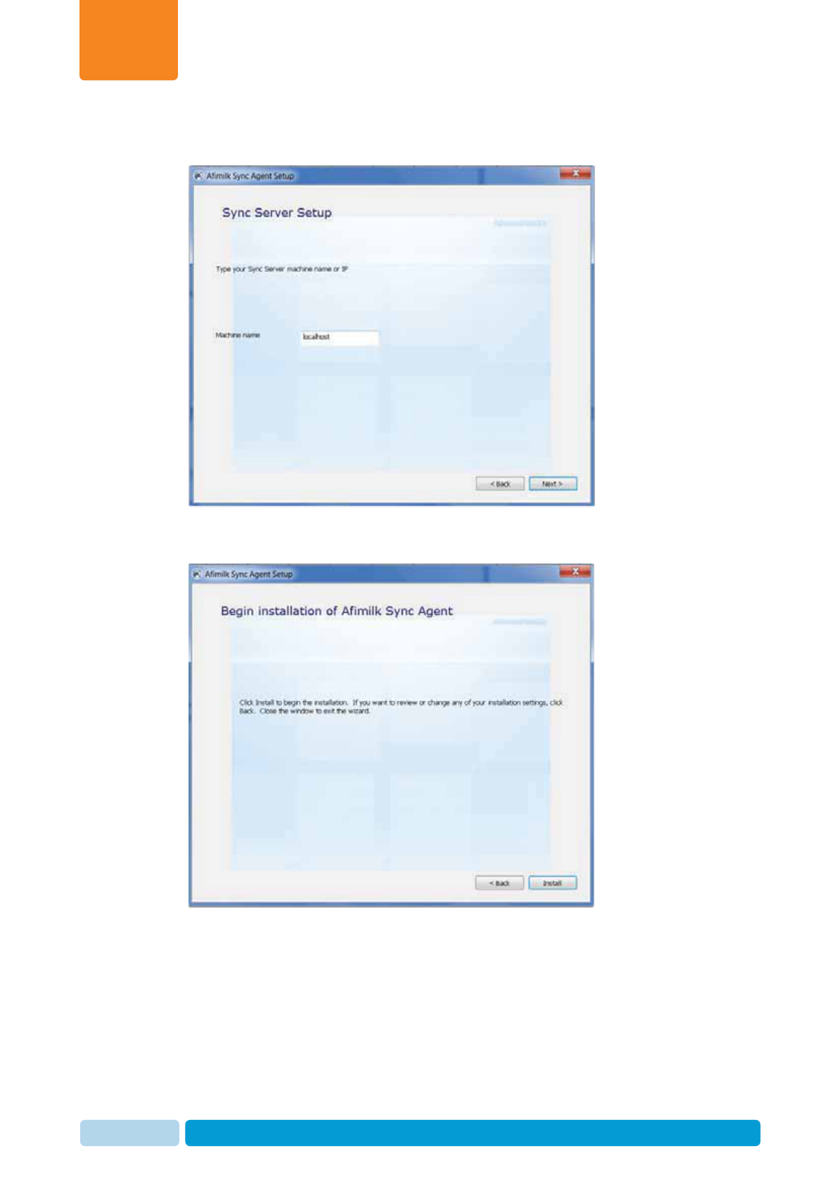
Install and Set AfiAct II Software
Chapter
4
Oct 2013 AfiAct II™ Installation Manual95
6. Click Next. The following dialog appears, indicating the default name of the
AfiFarm Server. Specify the name of Afifarm5 server.
7. Click Next. The following screen appears. Click Install to start the Sync agent
installation.

Install and Set AfiAct II Software
Chapter
4
Oct 2013 AfiAct II™ Installation Manual96
8. The following dialog appears, showing the installation process progress bar.
9. At the end of the installation click Finish.
The Sync Agent is installed.
Initial Reader Communication
Chapter
5
Oct 2013 AfiAct II™ Installation Manual97
5 Initial Reader Communication
Before mounting the Reader, connect the Reader to the local network (same
network as the computer) via a network cable, and verify connectivity with the
AfiFarm RT system. The AfiFarm RT System locates the Reader’s MAC and IP to
perform a handshake (RT sends a broadcast message searching for the Reader
unique ID; then the Reader replies to the sender (RT) providing its IP address).
Setting the Reader initial communication includes the following steps:
1. Connect the Reader to the wired network, see 5.1
2. Verify communication (handshake) via the RT system, see 5.2
3. If Wi-Fi is used, connect the Reader to the Wi-Fi network, see 5.3
4. Disconnect the Reader and transfer it to the shed, see 5.4
NOTE
After each Reader restart, wait until the Reader’s internal boot LED is
blinking, see 1.3.6
NOTE
It is recommended that the AfiAct II Reader initial connection is performed
immediately after the AfiAct II SW was installed.
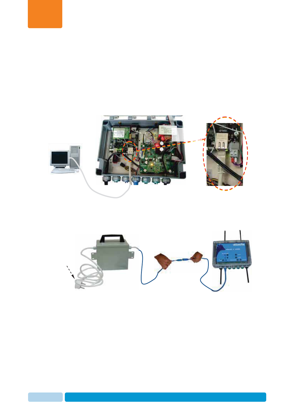
Initial Reader Communication
Chapter
5
Oct 2013 AfiAct II™ Installation Manual98
5.1 Connect the Reader to the Wired Network
A network cable is used for connecting the Reader to the PC. Then the Reader is
connected to the power source, and the connectivity is verified via the AfiFarm RT
system.
To connect the Reader to the network and obtain an IP address
1. Connect network cable: Open the Reader box and connect a network cable to
the Reader’s network connector. Connect the other side of the network cable to
the PC USB connector.
2. Connect to power: Use the power supply transformer box to power the Reader
on:
a. Connect the power transformer box cable to the Reader’s blue power cable.
b. Connect the transformer box to the power outlet.
blue
po
wer
ca
bl
e.
To power
outlet
Towards
PC USB
Connected
Network cable
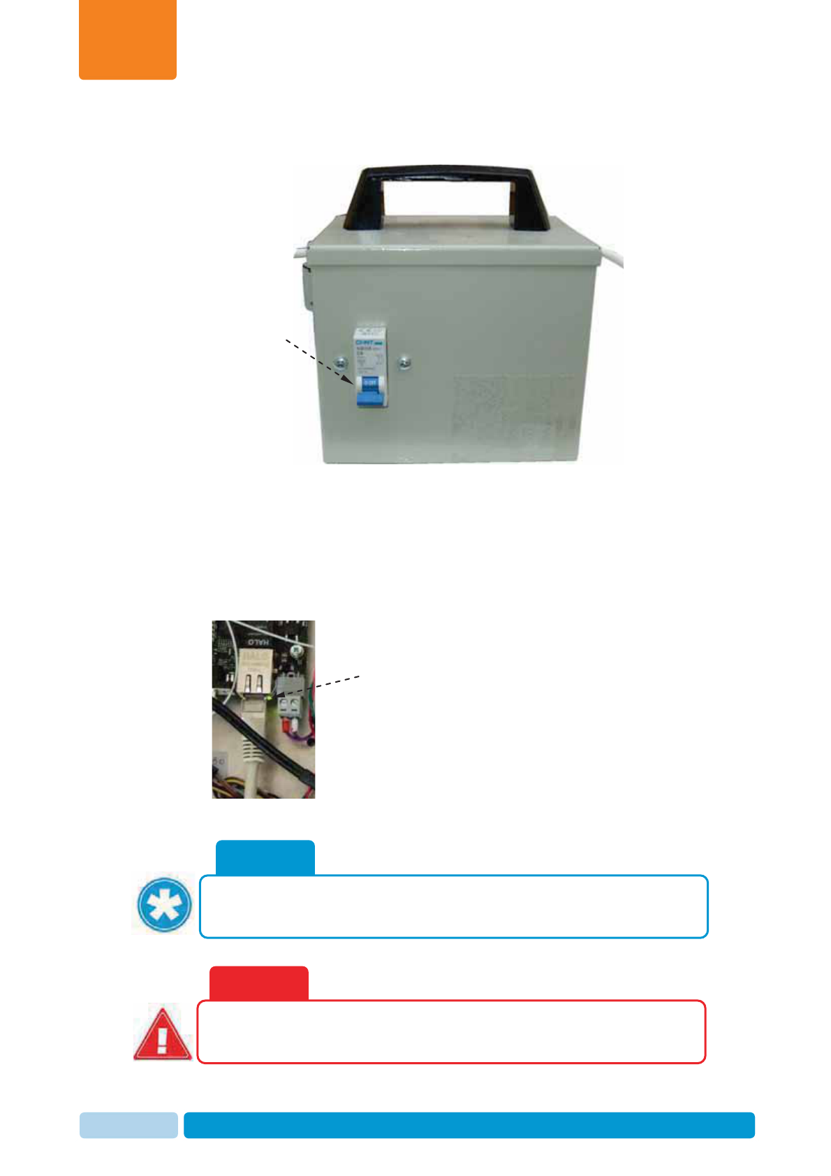
Initial Reader Communication
Chapter
5
Oct 2013 AfiAct II™ Installation Manual99
c. Turn on the transformer box switch, and verify that the Reader’s LEDs are
on.
3. If a DHCP exists and is configured to provide a dynamic IP to the Reader, the
Reader will automatically obtain an IP. If not, the Reader will use the factory IP
address 172.20.1.1.
The Connector orange LED indicates physical connection (physical link), and
the green LED blinks to indicate data flow over the network line. Verify that the
connection has been established by checking that the Reader’s main board
Computer Network Interface Card (NIC) is blinking green:
WARNING
Ensure taking all precautions when working with the high voltage
components.
NOTE
If the Reader does not show correct network connection (green blinks), restart
the reader by turning the power off and on again.
Turn ON
Blinking Green
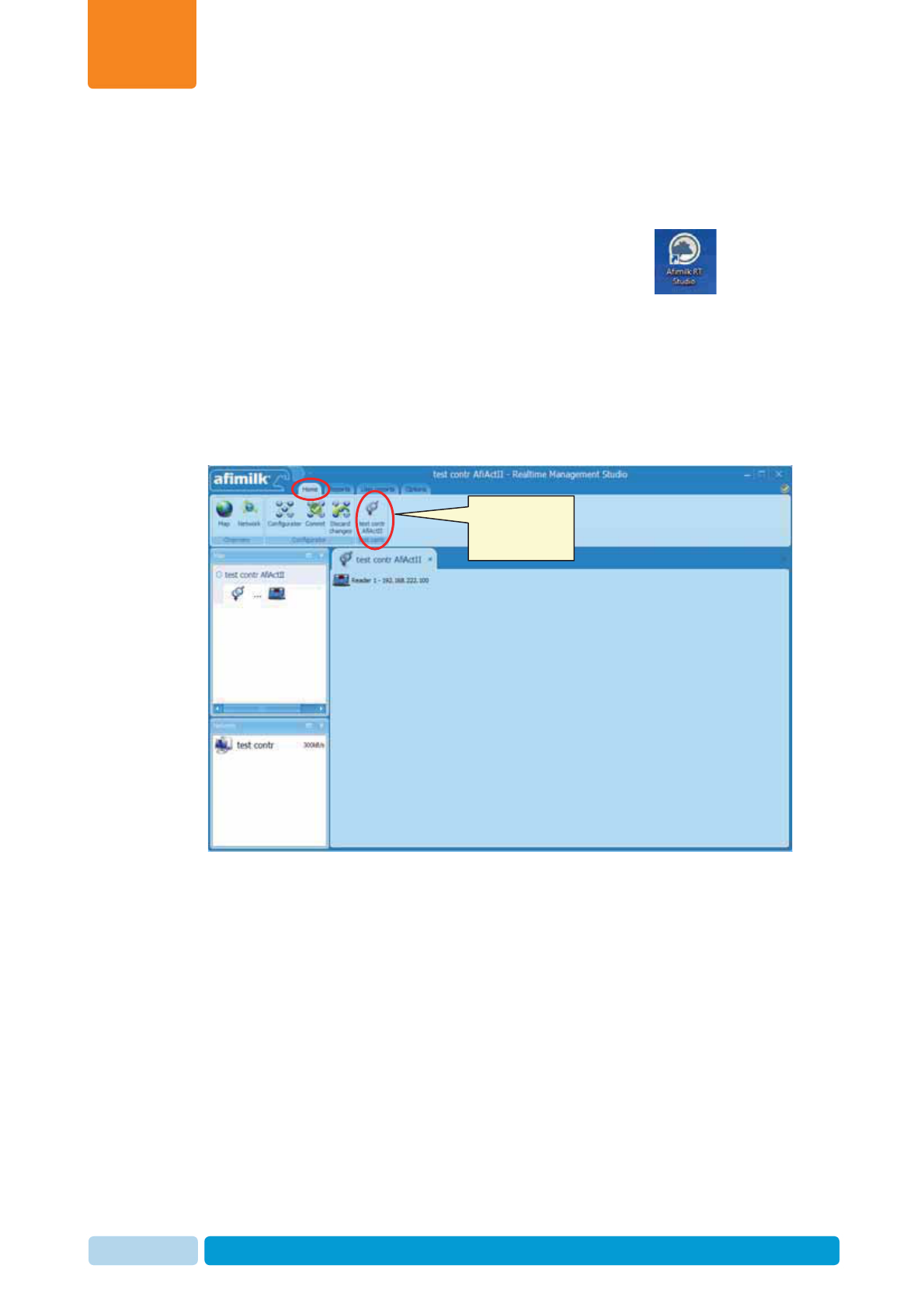
Initial Reader Communication
Chapter
5
Oct 2013 AfiAct II™ Installation Manual100
5.2 Verify Reader & RT System Communication
To ensure that the Reader handshake has been successful
1. (If not already open), open the AfiFarm RT system (click the icon).
2. In the login screen enter the login attributes:
xServer:localhost
xUser:admin
xPassword:admin
3. Under the Home tab, click on the new tab related to your controller (in this
example: Test Controller AfiAct II)
Click to view
network
elements
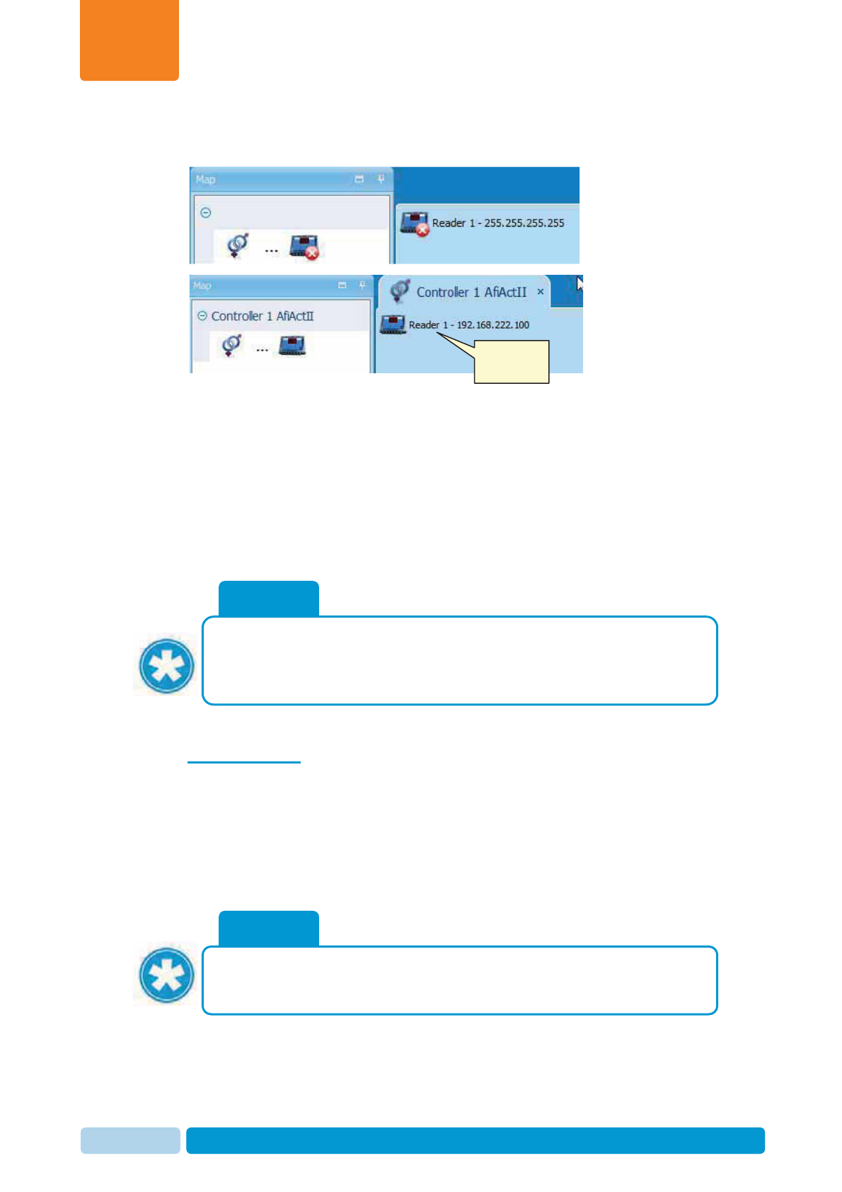
Initial Reader Communication
Chapter
5
Oct 2013 AfiAct II™ Installation Manual101
4. The connected elements (readers) are shown, and are most likely to appear as
disconnected (with a red X) during the first few seconds.
5. Wait a few seconds for the reader-controller connection to be established. When
the connection is established, the RT System will show the reader as
connected, with its relevant IP address, indicating that the Reader and RT
system Controller are now communicating. In addition, the Reader’s PC Comm
LED will show that the Reader and PC are communicating.
Write down this reader’s dynamic IP address (in the above example:
192.168.220.100).
Note: When there is no DHCP mechanism, you may use the Reader static IP
address 172.20.1.10 for back-to-back connection, see 9.5
5.3 If Needed: Set Wi-Fi Communication
If the Reader is to use Wi-Fi communication, the Reader should be connected to the
Wi-Fi network at the office, before proceeding with the Reader mounting. This is
done via the Reader’s direct Wi-Fi networking GUI application (Luci), (accessed
via the PC browser), which allows manual management and troubleshooting of the
connection between the Reader’s main board and the local network (e.g: entering
the Wi-Fi network SSID (Service Set Identifier) manually).
NOTE
If there is NO Wi-Fi coverage in the office, the Wi-Fi network assignment will
be set in the office as shown below, and the verification will be performed in
the shed
(
Wi-Fi communication LEDs
)
.
NOTE
For troubleshooting - The Reader is provided with a label showing its ID (and
MAC), to which an IP address will be assigned during the connection
procedure. You may obtain the IP address that has been assigned to your
Reader, by using a standard IP/MAC scanner application (e.g. ip-scanner).
Connected
reader
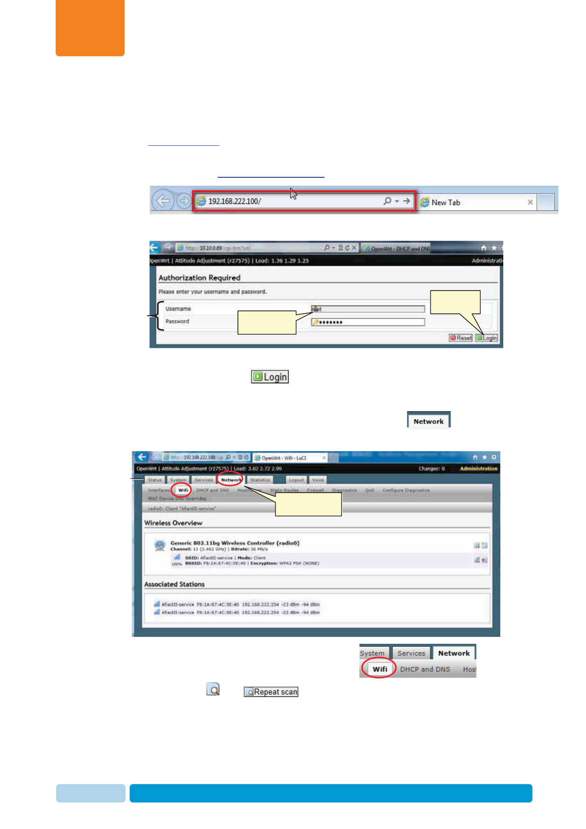
Initial Reader Communication
Chapter
5
Oct 2013 AfiAct II™ Installation Manual102
To Connect Wi-Fi Communication
1. Open your PC browser and enter the Reader interface by typing the following in
the browser’s navigation bar:
http://170.20.1.1
(Note: Alternatively – you may also enter the IP address (Obtained from the
Reader’s map): http://reader_ip_address).
The login screen appears:
2. Enter the Reader username and password (default: user: root, password:
afimilk). Then click the button.
3. In the displayed Reader communication options, select the tab from
the navigation options.
4. Under the Network tab sub-options select Wi-Fi ,
and click the (OR ) button at the bottom of the page to obtain
the list of available Wi-Fi networks.
Login
area
Click to login
Enter username
and password
Navigation-
tabs
Select to access
network options
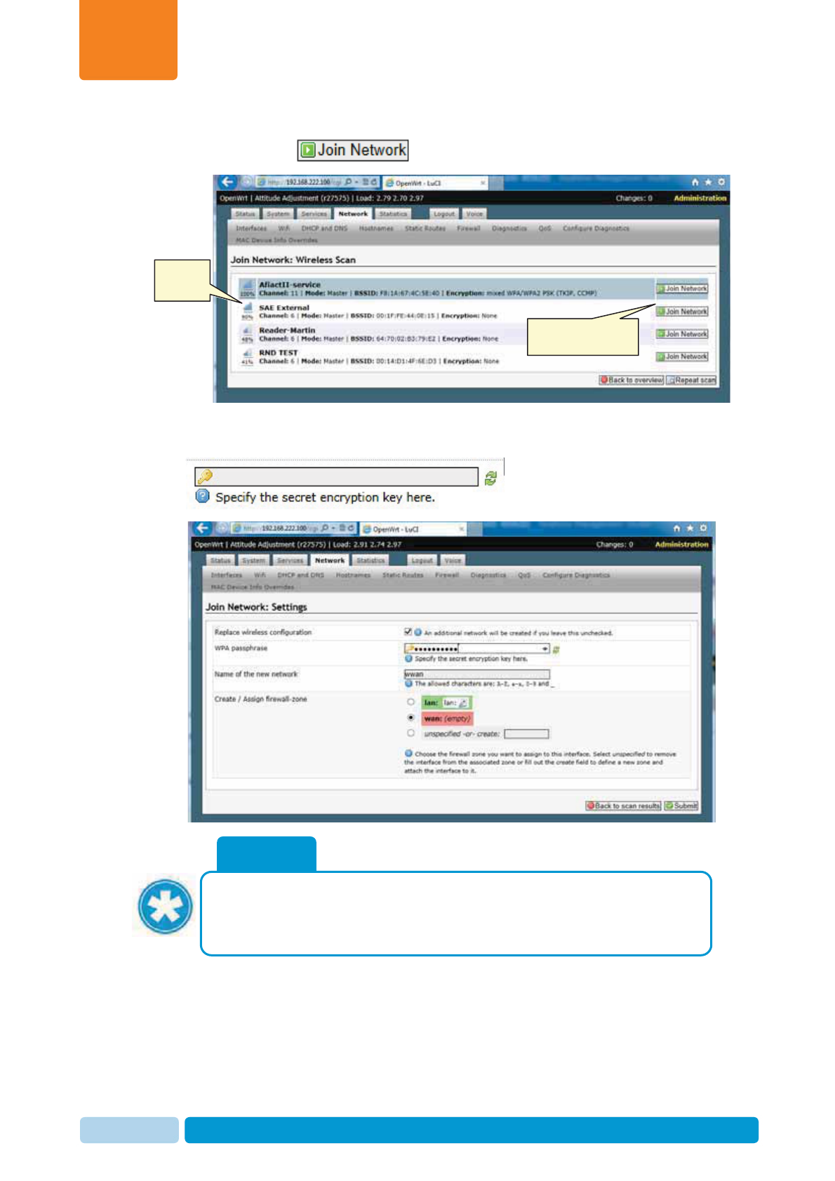
Initial Reader Communication
Chapter
5
Oct 2013 AfiAct II™ Installation Manual103
5. From the displayed list of available networks, select the requested network
and click the button.
6. If the network is secured, the system will wait for the user to enter the protocol
used and the password. Type the Wi-Fi Network password in the correct place:
NOTE
It is the user’s responsibility to verify that the correct password had been
entered. Entering a wrong password will end with no network connection, and
the whole process will need to be performed again (starting at phase 1
above
)
Click to connect to the
selected network
Selected
network
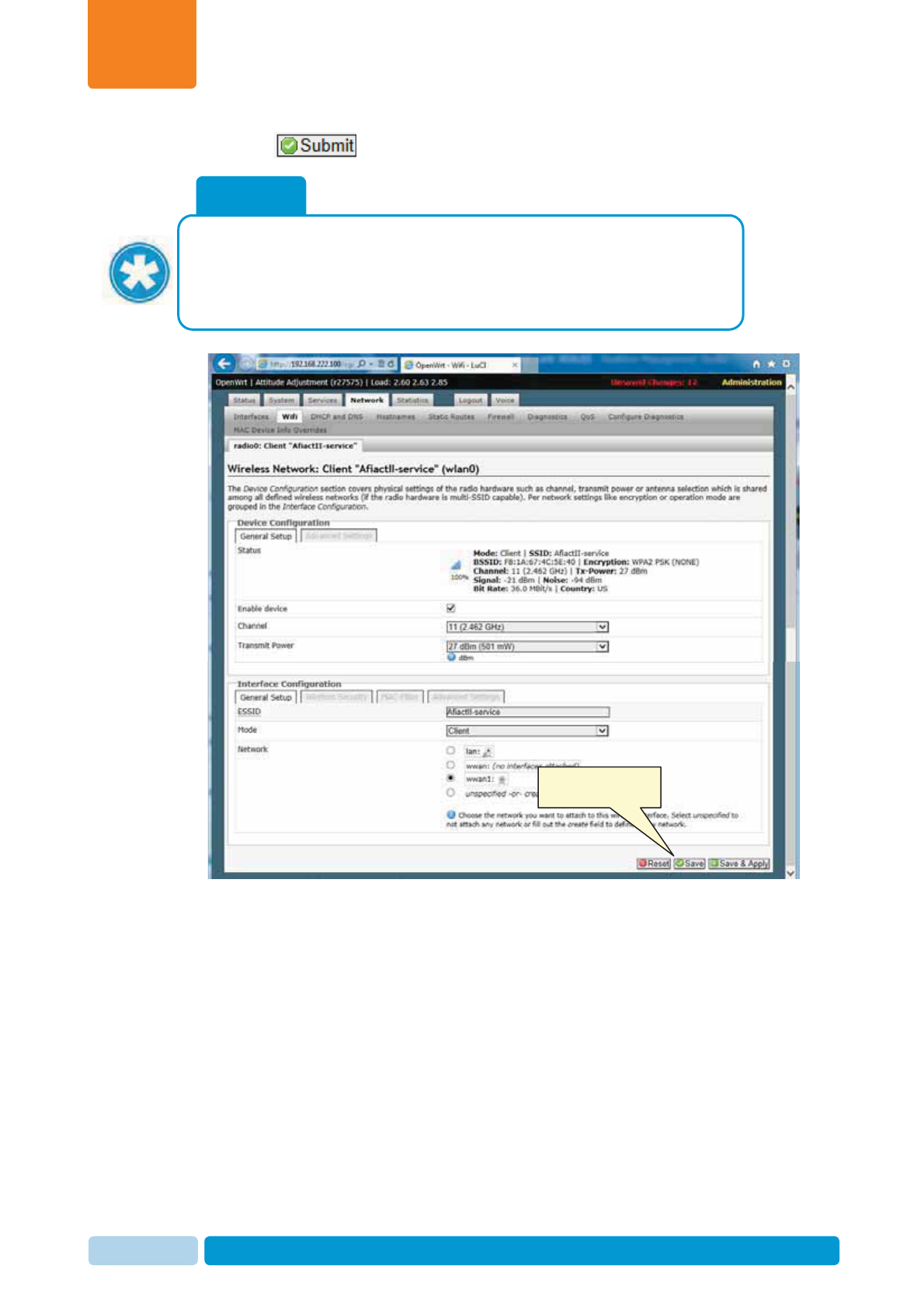
Initial Reader Communication
Chapter
5
Oct 2013 AfiAct II™ Installation Manual104
7. Click at the button to submit the new configuration.
8. In the displayed screen all the details that will be sent to the device are
displayed. Roll down and click Save & Apply.
NOTE
To ensure that the connection to the wireless network is generated with the
correct parameters, it is recommended that the WAN interface settings are
deleted at this stage (only if the interface already exists) OR
if there are problems connecting due to wrong network name – add the digit 1
to the name and re-tr
y
.
Click to connect to the
selected network
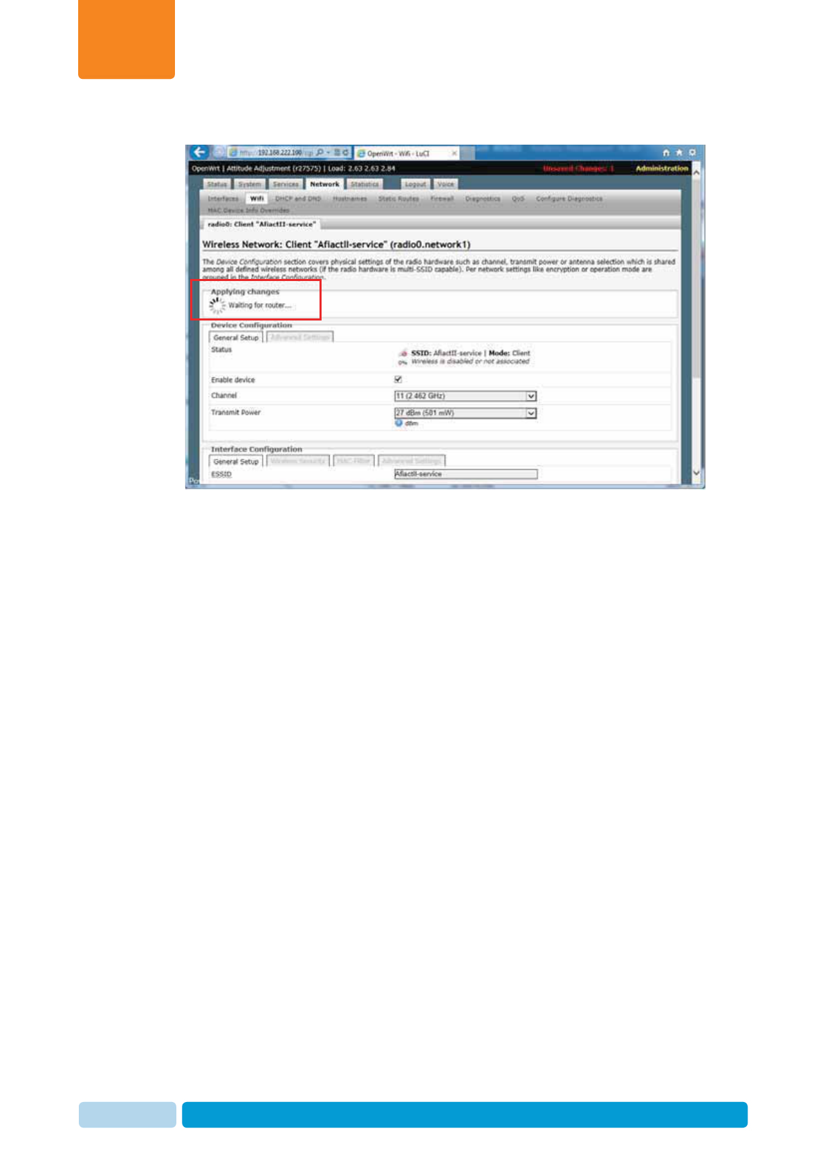
Initial Reader Communication
Chapter
5
Oct 2013 AfiAct II™ Installation Manual105
9. Wait until the system is connected.
Note: If the connection takes too long (more than 30 seconds), restart the
Reader (POWER OFF and then back ON.
10. Verify that all the Wi-Fi LEDs (WLAN & signal strength) on the Reader are ON
(see 1.3.1). If the Wi-Fi LEDs don’t work then you will have to start this stage
from the beginning.
11. After connecting to the wireless network, disconnect the network cable and re-
start the Reader:
a. Use the transformer power button to turn the device off.
b. Disconnect the network cable.
c. Power the Reader ON using the transformer switch
d. Wait for the device to locate the network (~1 minute).
e. The communication verification is now done by checking:
x All the Wi-Fi (WLAN & signal strength) LEDs on the Reader are ON
x The PC Comm LED is ON, indicating Reader / PC software connection
x The AfiFarm RT system displays the Reader’s IP, see 5.2
f. Close the Reader configuration interface (browser)
5.4 Disconnect and Take the Reader to the Shed
1. Switch off the Reader’s power via the transformer box switch.
2. Disconnect the Reader from the power cable (and from the network cable, if not
already disconnected).
3. Close the Reader enclosure securely.
4. Bring the Reader, transformer box, laptop, and all other elements to the shed.
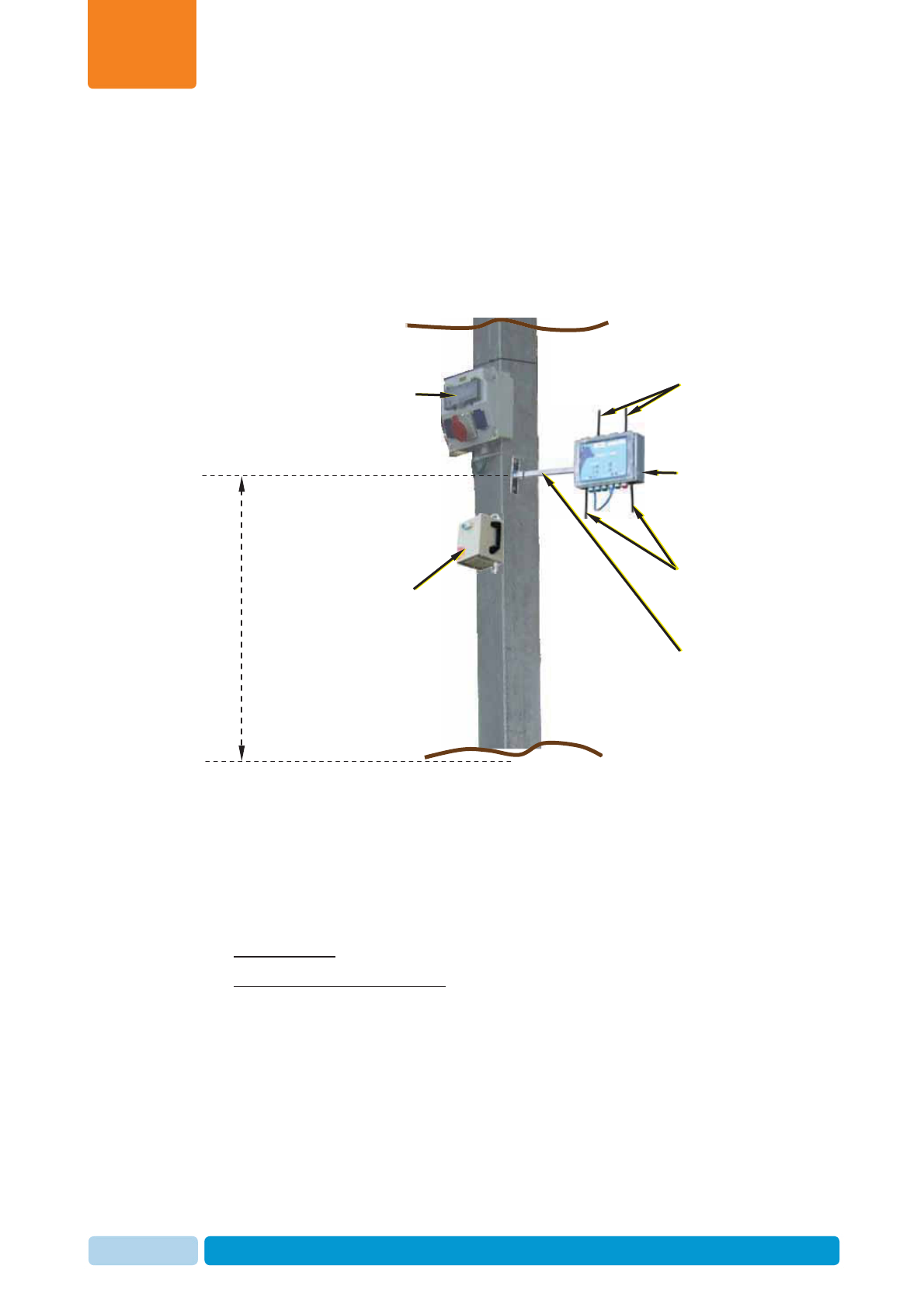
Mount the Reader
Chapter
6
Oct 2013 AfiAct II™ Installation Manual106
6 Mount the Reader
After configuring the Reader, mount the Reader and its power elements in the
location determined previously (see 2.1, 2.2), after verifying that there is both tag
and network coverage in the cowshed (Wi-Fi or cable, as determined by the
customer).
6.1 Mounting Location Verification
Verify the mounting location according to the following steps:
1. Check that the location has been properly defined (see 2.1, 2.2)
2. Connect the Reader to the power temporarily, see 6.1.1
3. Verify tag communication, see 6.1.2
4. If Wi-Fi is used: Verify Wi-Fi coverage, see 6.1.3
5. If wired communication is used: connect the communication cable, see 6.1.4
6. Disconnect the Reader from the temporary power connection, see 6.1.5
Bracket
arm
Reader
Antennas
(towards tags)
Power
box
Wi-Fi Antennas
(towards PC)
Power
outlet
Ground
Cowshed
roo
f
3.5 m
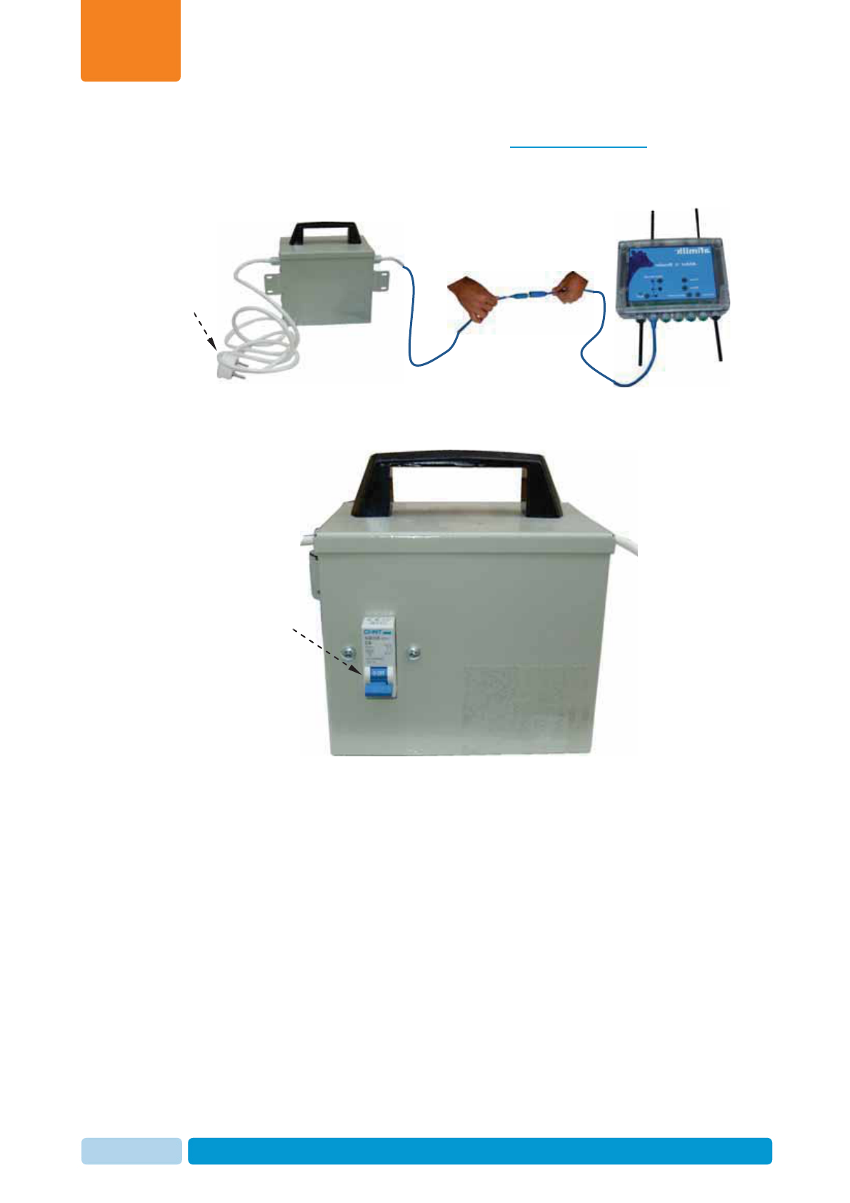
Mount the Reader
Chapter
6
Oct 2013 AfiAct II™ Installation Manual107
6.1.1 Connect the Reader to the Power TEMPORARILY
To connect the Reader to the power supply temporarily:
1. Connect the power transformer box cable to the Reader’s blue power cable.
2. Connect the transformer box to the power outlet.
3. Turn on the transformer box switch, and verify that the Reader’s LEDs are ON.
power cable.
To power
outlet
Turn ON
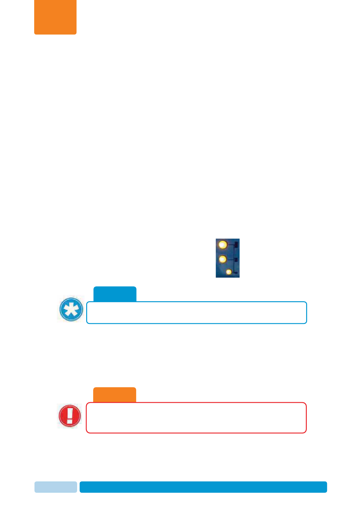
Mount the Reader
Chapter
6
Oct 2013 AfiAct II™ Installation Manual108
6.1.2 Tag LR RF Survey
To verify tag communication:
1. Change the Reader’s transmission interval to 5 minutes, see 4.3.3 (the Reader
will automatically change the Tags transmission interval to correspond to the
Reader, so ther5e is no need to update test tags via the RPU).
2. Change the Reader’s transmission interval via the RT System configurator to 5
minutes (before going out), see 4.3.3.
3. Locate tags statically at the required coverage area borderline.
4. Turn on the Reader. Make sure the PC Comm LED is on, see 1.3.1
5. Wait 15 minutes, check the Activity Log Report, and verify that all of the tags
are identified in the report, with a message every 5 minutes.
6. When the location is approved, mount the Reader and set the steady state
interval back to the default (15 minutes) in the configurator only.
6.1.3 If Wi-Fi is used: Coverage Verification
To test the mounting point for proper Wi-Fi coverage
Verify that at least two stable Wi-Fi Signal Strength LEDs (i.e. Low and Medium) are
ON, indicating strong signal, see 1.3.1
Note: If the 2nd (Medium-strength) LED is not
lit steadily (i.e. blinking) it is not good enough!
6.1.4 If Wired Communication is used: Setup
To connect the Reader to the network cable
1. Open the Reader box and REMOVE the RED grommet: Unscrew the grommet
nut and remove the grommet.
CAUTION
Remove a plug only where a cable will replace it. If grommet holes are
left open, the box will not be waterproof, and components may be
damaged.
NOTE
For troubleshooting the connection, use back-to-back connection to your
la
p
to
p
, see 9.5
Good signal strength
Medium signal strength
Low signal strength
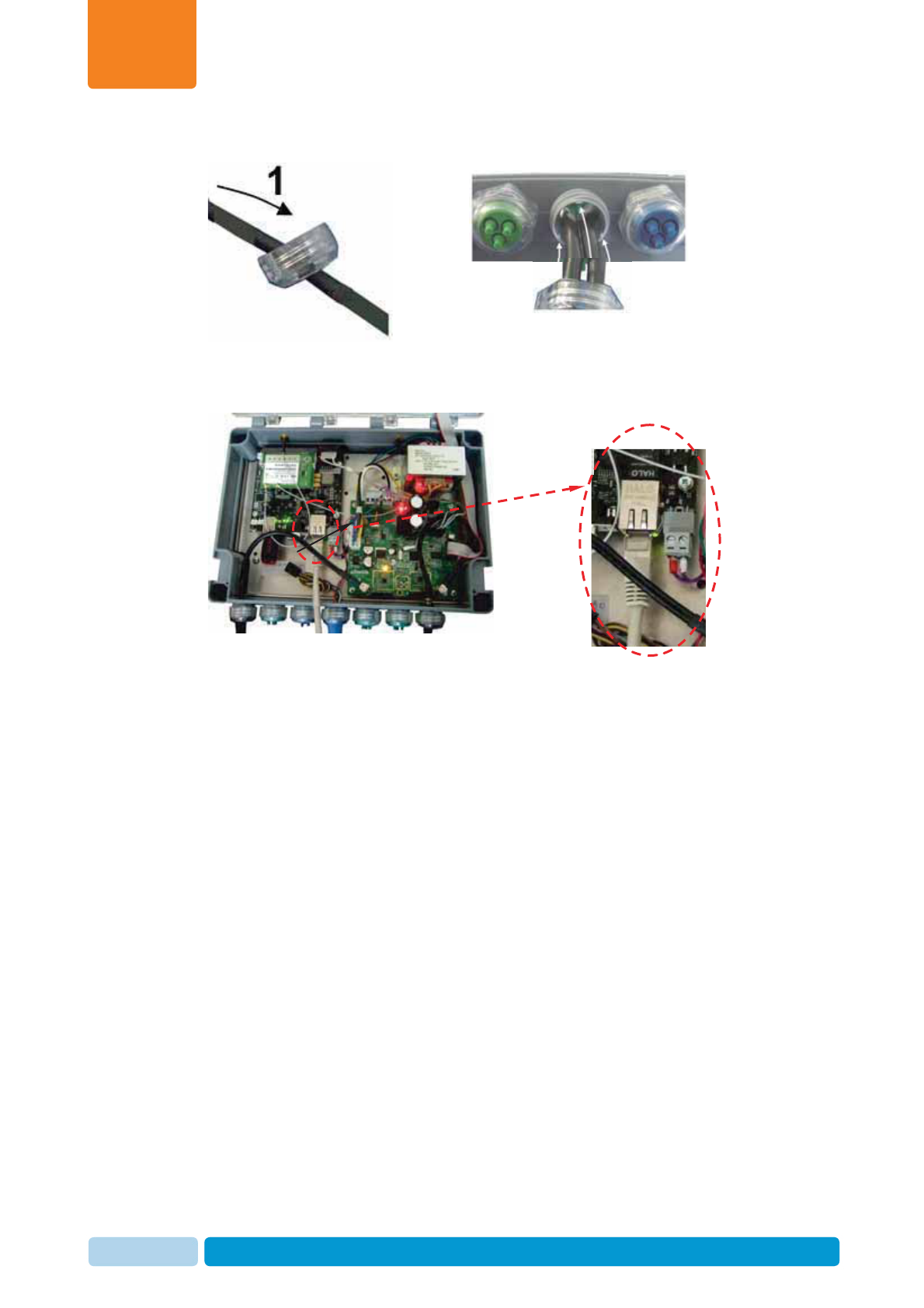
Mount the Reader
Chapter
6
Oct 2013 AfiAct II™ Installation Manual109
2. Insert the network cable through the nut into the socket.
3. Rotate the nut one revolution on the threads, so that it is loosely held in position.
4. Connect the network cable to the Reader’s network connector.
5. Close the Reader enclosure securely.
6. Verify that the Reader and RT System are communicating, see 5.2
6.1.5 Disconnect the Reader from the Power
To disconnect the Reader from the temporary power connection
1. Switch off the Reader’s power via the transformer box switch.
2. Disconnect the Reader from the power cable.
3. Close the Reader enclosure securely.
Position grommet slots,
for rotation-proof stability
Connected
Ethernet cable
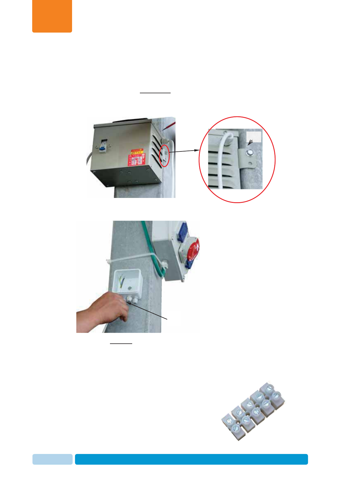
Mount the Reader
Chapter
6
Oct 2013 AfiAct II™ Installation Manual110
6.2 Mount the Power and Electricity Boxes
1. Connect the power supply unit to the pole, near the power outlet access:
x Locate the box on the pole, higher than the cows can reach but accessible
for maintenance. If necessary - bend the bracket ear manually to fit the
pole.
x Use the electric screwdriver to screw the bracket to the pole.
2. Open the electricity box and screw it to the pole, preferably close above the
power box, using the supplied screw and an electrical screwdriver.
3. From the free end of the white power cable, strip 2 inches of the insulation to
expose the conductors. Then insert the cable into the electrical box through its
lower connection holes.
4. Thread the exposed blue and black conductors into a cable terminal box.
“Ear”
Insert
cable
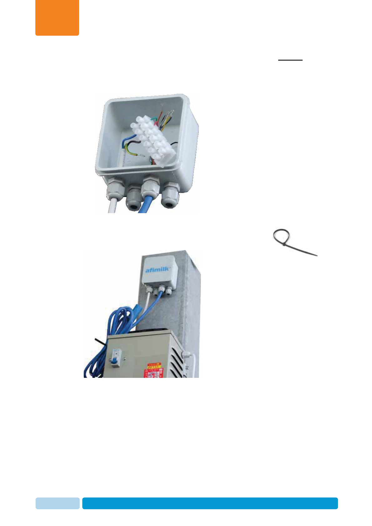
Mount the Reader
Chapter
6
Oct 2013 AfiAct II™ Installation Manual111
5. Strip 2 inches of the insulation of the blue extension power cable’s free end, to
expose the conductors.
Insert the exposed green and red cable-ends into the electrical box and thread
the conductors into the cable terminal box.
6. If the blue cable has loose ends, secure the cable to the power box using cable
ties.
7. Close the electrical connection box.
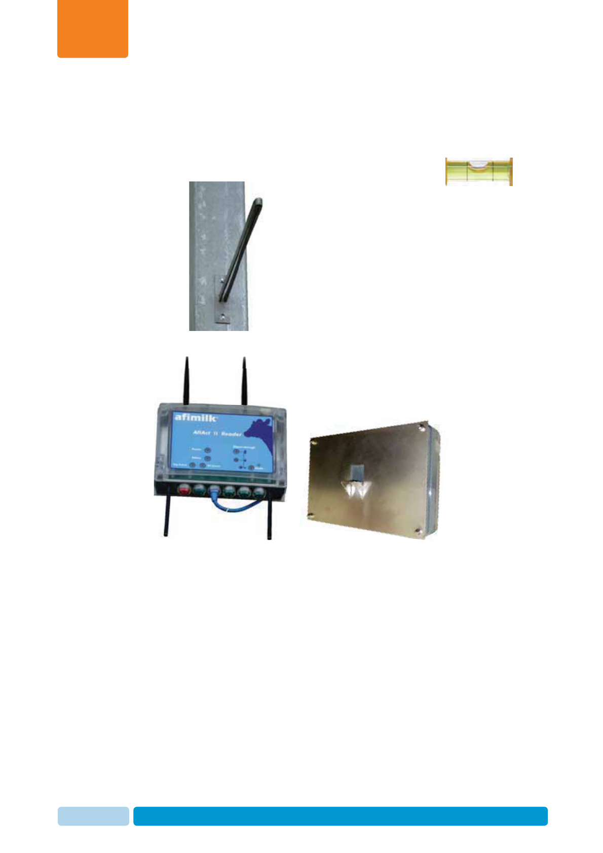
Mount the Reader
Chapter
6
Oct 2013 AfiAct II™ Installation Manual112
6.3 Mount the Reader to the Pole
1. Connect the bracket arm to the pole (3.5 meters from the ground level):
x Use the supplied screws and an electrical screwdriver.
x Verify that the bracket arm is leveled (use a leveling device).
2. Verify that the Reader antennas and bracket plate are assembled. If not – refer
to 3.
o
3
.
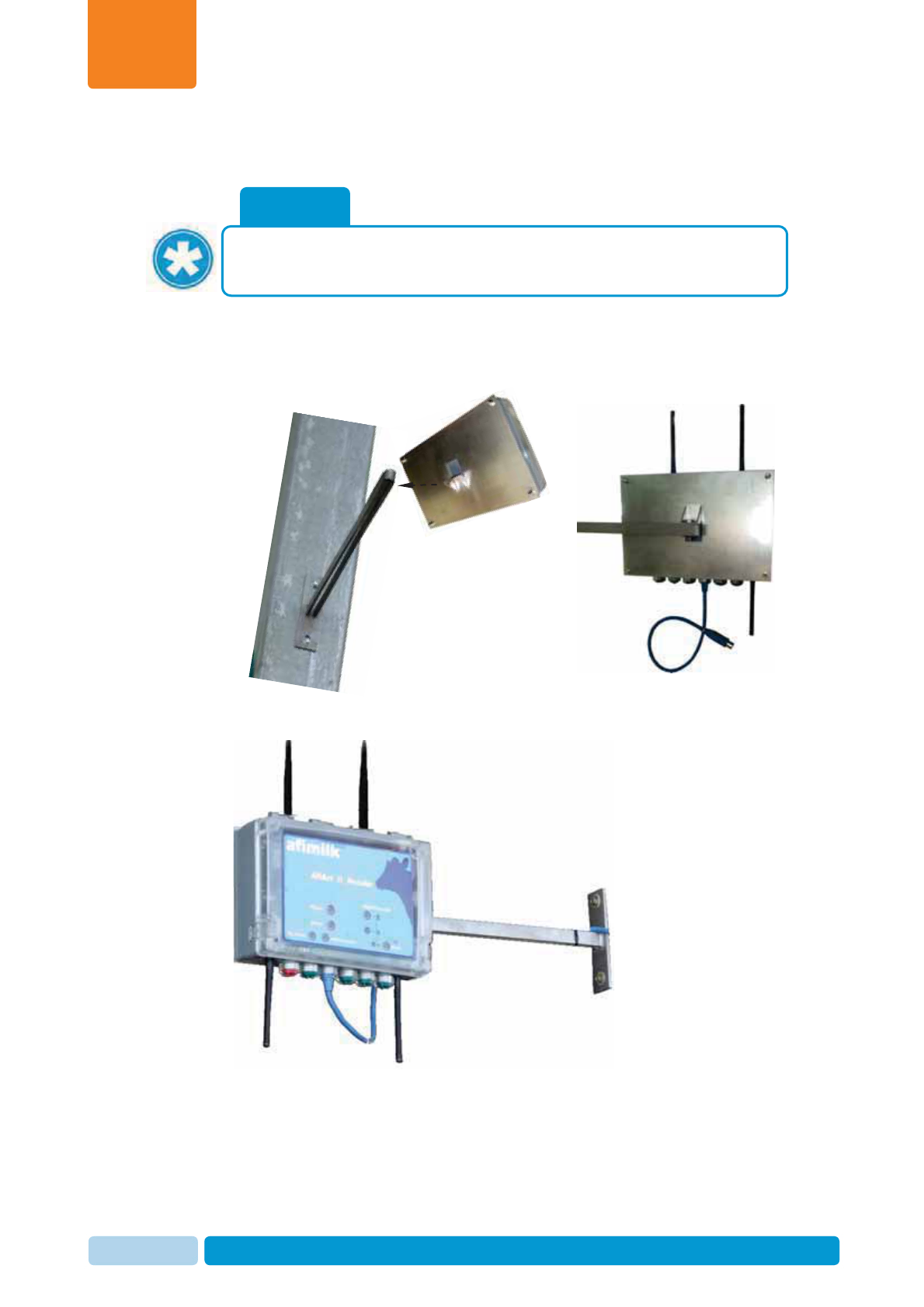
Mount the Reader
Chapter
6
Oct 2013 AfiAct II™ Installation Manual113
3. Insert the bracket arm’s free end into the plate attached to the Reader, and
screw them together.
The Reader is now mounted on the pole.
NOTE
Before screwing the Reader to the arm, “play” with the Reader and antennas
angle, until optimal transmission is shown via the Wi-Fi signal strength LEDs.
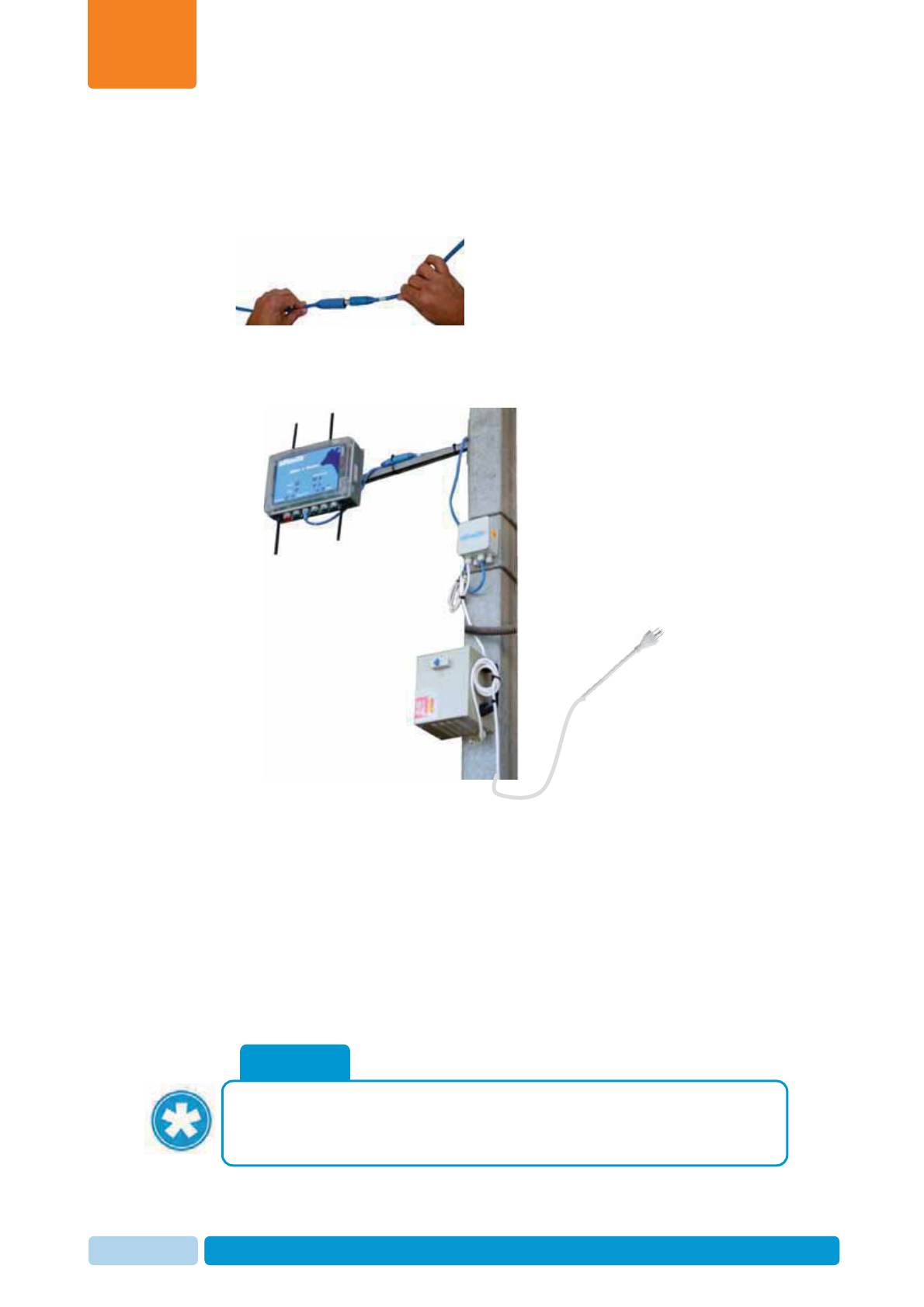
Mount the Reader
Chapter
6
Oct 2013 AfiAct II™ Installation Manual114
6.4 Connect the Reader to Power
1. Connect the blue power cable from the Reader and the blue cable from the
electrical power box.
2. Make sure that the blue power cable does not dangle under the Reader – it
should not be parallel to the antenna. Secure the connector and remaining blue
cable to the bracket arm using cable ties.
3. Connect the power box to the power outlet.
4. Power the Reader on, using the power switch located on the power box. Verify
that the LEDs show good reception for both tags and Wi-Fi, see 1.3.1
5. When done with the installation, wait to see that the Activity Log Report is
being updated with tag messages.
Note: You may set the Reader’s transmission interval via the RT System
configurator to 5 minutes (see 4.3.3), so that you will be able to check that all
tags transmit, within no longer than 15 minutes, and then change it back to 15
minutes. The tags can be viewed in the Activity log report, see Appendix C
NOTE
Before the system may be used for detecting cows in heat, average behavior
performance baseline should be generated by the application. This can take 5
to 6 days.
Towards
power
outlet
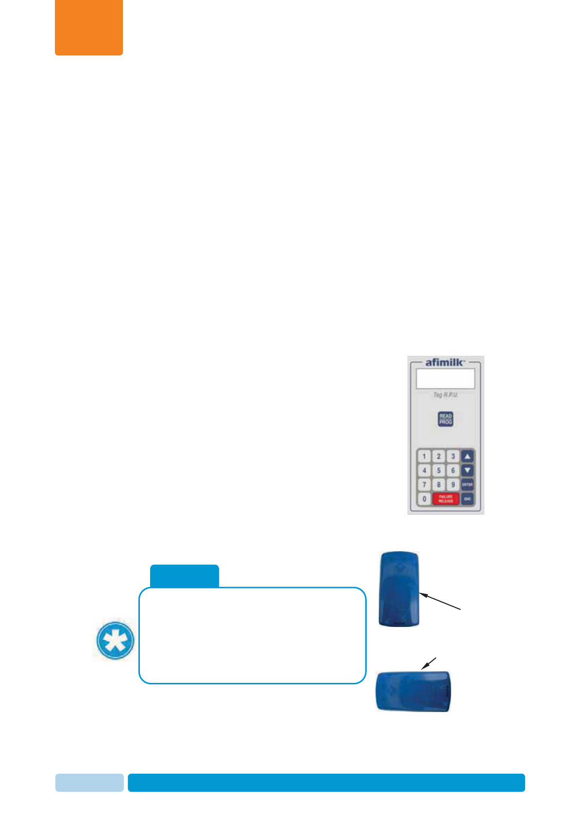
Handle AfiTag II
Chapter
7
Oct 2013 AfiAct II™ Installation Manual115
7 Handle AfiTag II
AfiTag II is responsible for continuously sending cow data to AfiAct II system. It is
factory-set to use the specific frequency and channel corresponding to your region.
It is the farmer’s responsibility to attach the tags to all cows in the group and enter
their ID into the system. Furthermore, when a cow is removed from the group, it is
the farmer’s responsibility to remove the tag from its leg and inform the system. A
removed tag may be stored or immediately re-used on another animal.
The tag is attached to the cow’s leg using a flexible strap. It is mandatory to use an
original afimilk strap.
This chapter provides detailed instructions for tag management:
x Tag attachment, see 7.1
x Tag replacement (when a tag is moved from one animal to another) , see 7.2
x Tag storage, see 7.3
Note: Technicians may manage (i.e. read and program) tag
data via the Tag Reading/Programming Unit (RPU).
This includes changing channels, when needed (e.g. if the
pre-set factory channel does not function due to interference).
In this case, the Reader’s channel frequency must also be
changed to correspond with the tags channel (see 4.3.3)
For a description of the basic actions done via the RPU, refer
to Appendix B. For full usage instructions of RPU, refer to the
RPU document (see referred documents on page vii).
NOTE
The tags only transmit when held in vertical
position. Therefore, when tags are transported,
ensure they are in horizontal position.
When a cow is lying down, the data is
collected, but will only be transmitted when the
cow is up again.
Tag transmits
Tag does not
transmit
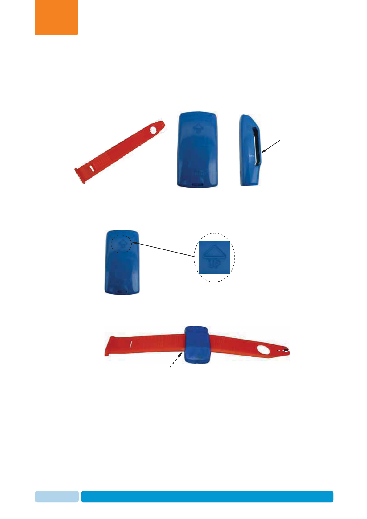
Handle AfiTag II
Chapter
7
Oct 2013 AfiAct II™ Installation Manual116
7.1 Attach AfiAct II Tags
To attach the tag onto a cow’s leg:
1. Identify the tag elements, as shown below:
2. Connect the strap to the tag as follows:
a. Locate the tag with the arrow pointing upwards.
b. Insert the narrow side of the strap through the back of the tag’s “ear”.
c. Pull the strap to the right, until it is locked in the tag’s “ear”. (Ensure the
strap is locked by pulling it back).
Tag arrow pointing
upwards
Tag “ear”
Tag front view
Insert strap through tag ear.
Strap
Tag side view
Insert strap through tag ear.
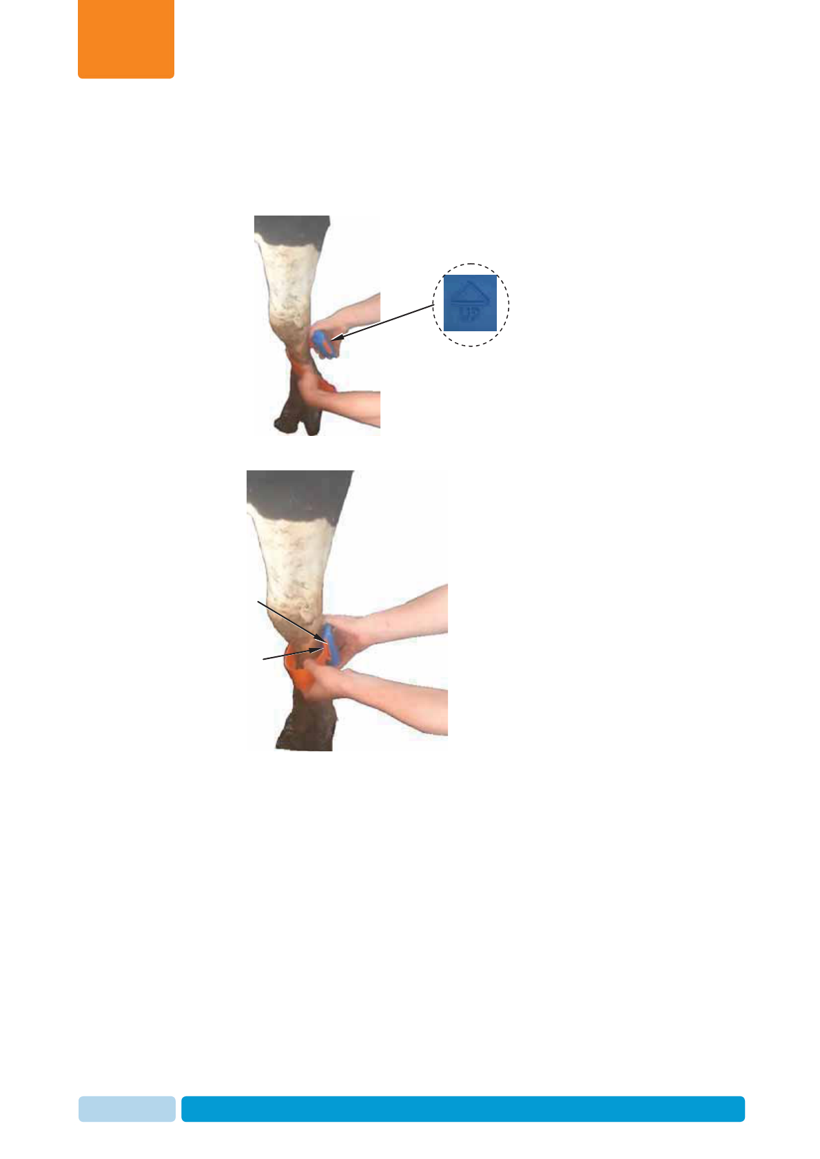
Handle AfiTag II
Chapter
7
Oct 2013 AfiAct II™ Installation Manual117
3. Prepare all tags for attachment as described in steps 1, 2.
4. Apply the tag to the cow’s leg as follows:
a. Position the arrow of the tag upwards and wrap the strap around the cow’s
leg above the hoof, about 20cm/8inch above floor level.
b. Insert the narrow side of the strap through the tag’s ear.
Tag arrow
pointing upwards
Narrow side
of strap
Tag ear
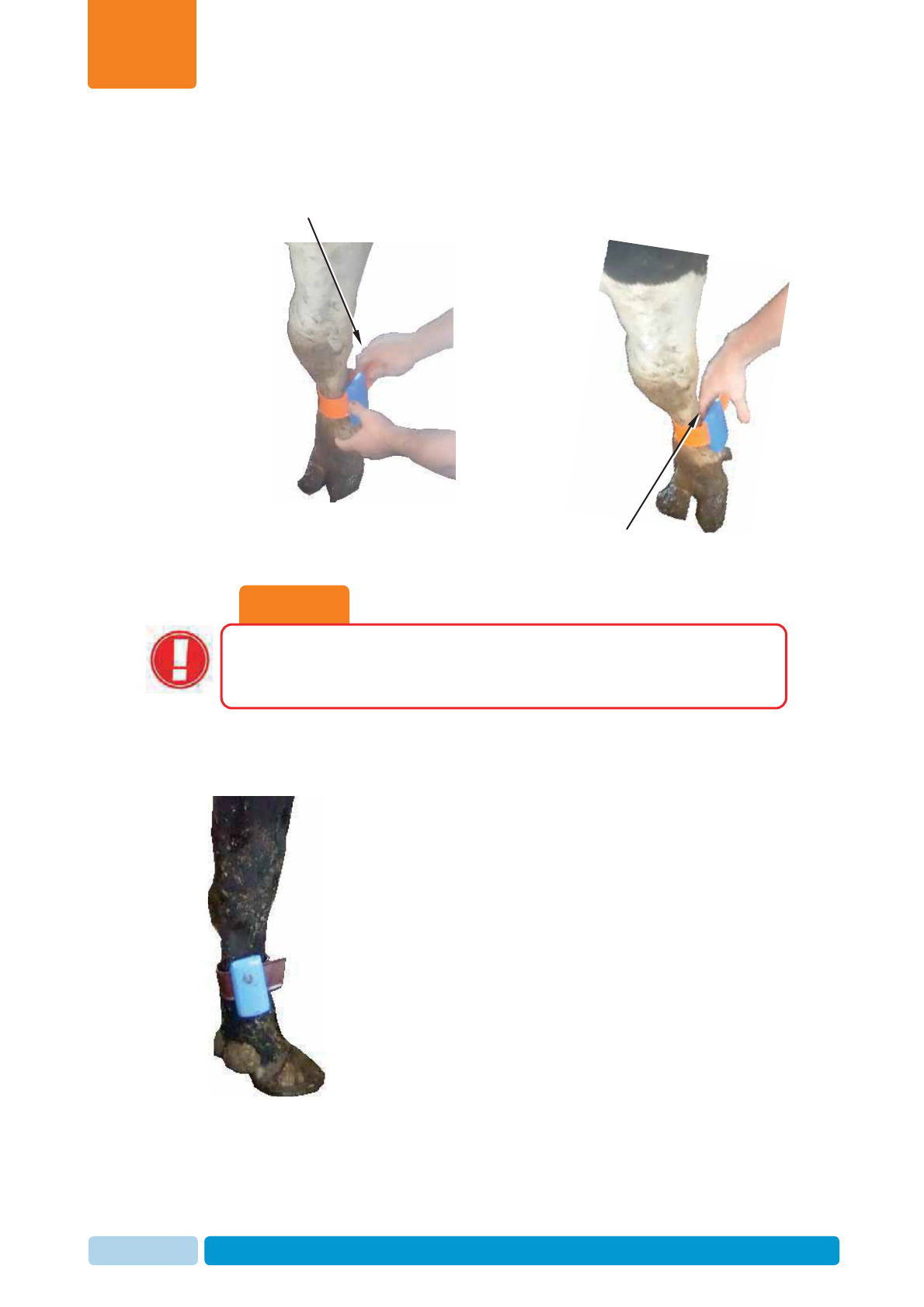
Handle AfiTag II
Chapter
7
Oct 2013 AfiAct II™ Installation Manual118
c. Pull the strap through the ear, ensuring the tag is not too tight, by inserting
two fingers between the strap and the cow’s leg.
5. Cut off the excess length of strap.
6. Keep a record of each cow with its corresponding AfiTag II number.
7. When entering a new cow into AfiAct II software, enter its corresponding AfiTag
II number. See 8.
CAUTION
The AfiTag II attached to a cow should be loose enough to rotate freely
around the cows’ leg, to avoid injuries or leg disease. This is especially
important with heifers, where the legs are still growing.
Pull strap
Two fingers distance
between tag and cow’s leg
Handle AfiTag II
Chapter
7
Oct 2013 AfiAct II™ Installation Manual119
7.2 Replace Tags
AfiTag II can be transferred from one cow to another, for example, on the following
occasions:
x Removing from culled cows.
x Removing from cows that are dry until the time of their calving.
x Removing from a heifer that is ready for calving.
As the legs of a heifer grow, the straps can become too tight. In this case, it is highly
recommended to remove the tag from a heifer before calving (if heifer heat detection
is used). When the heifer starts its first lactation, the tag can be reattached with new
straps.
To ensure proper maintenance and storage of tags and increase tag longevity,
handle tags as follows:
xWhen removing a tag from a cow's leg, cut off the strap. Do not re-use straps.
x AfiTags II are encased in sealed plastic containers. A tag can be washed under
running water (warm or cold) before storage or before attaching to new cows.
However, tags should not be soaked in water for long periods (hours) of time.
CAUTION
Soaking AfiTags in water for hours may reduce their life expectancy.

Handle AfiTag II
Chapter
7
Oct 2013 AfiAct II™ Installation Manual120
To remove a tag or move it to another animal’s leg:
1. Use pruning-shears and carefully cut the strap of the attached tag.
2. Hold the tag removed from the cow’s leg and use Leatherman pliers to remove
the remaining strap edges as demonstrated below:
a. Insert the pliers into the tag-ear and grip one of the strap edges.
y
c
Insert pliers into the tag ear.
Strap edges to be removed
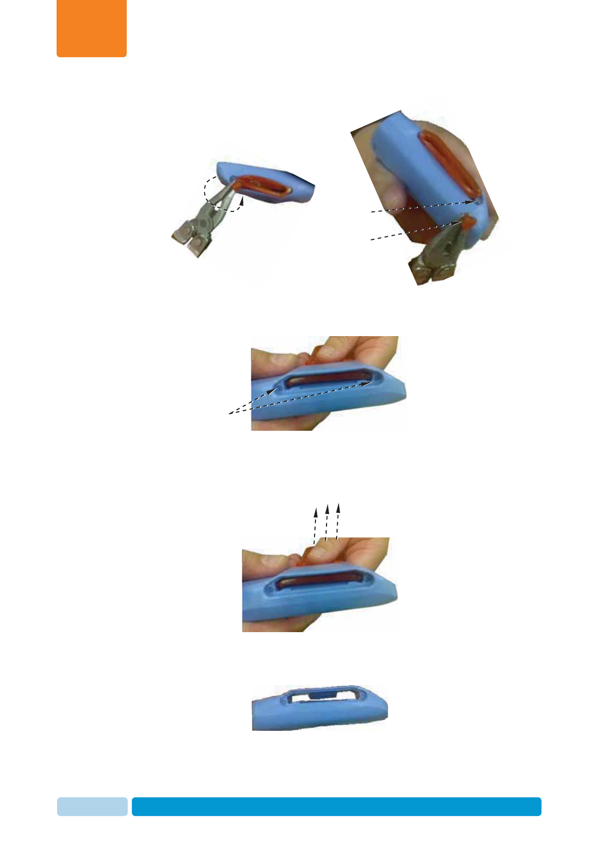
Handle AfiTag II
Chapter
7
Oct 2013 AfiAct II™ Installation Manual121
b. Twist the strap edge using the pliers, until the edge breaks off, leaving the
tag corner clear.
c. Repeat phase B with the second edge, leaving two clear corners.
3. Pull the strap out of the tag.
4. Your tag is now clear for re-use or storage. Make sure you record each cow
with its corresponding AfiTag number. When a tag is removed – inform the
system of the removed/replaced tag and the reason (e.g. culling), See 8.
o
ff
,
Twist
Edge breaks of
f
Clear tag corner
Clear tag corners
Pull strap out of tag
Handle AfiTag II
Chapter
7
Oct 2013 AfiAct II™ Installation Manual122
7.3 Store Tags
When necessary, AfiTag II should be stored in a dry protected area. Storage should
be at least 1 meter (3 feet) away from any radiating device such as main power
cables, PC screens, electric crowd gates, and other high power devices.
In order to save battery life, it is recommended to lay the tag horizontally.
Following all recommendations for AfiTag II care will ensure smooth operation and
maximize AfiTag II longevity.
CAUTION
Radiating devices may create an electromagnetic field that energizes the
AfiTa
g
s
,
thus shortenin
g
their life ex
p
ectanc
y
.

Enter Herd’s Data into AfiFarm
Chapter
8
Oct 2013 AfiAct II™ Installation Manual123
8 Enter Herd’s Data into AfiFarm
Animals to be tracked by the system must be entered into the AfiFarm application.
The interface for entering the data depends on your specific configuration as
follows:
x For standalone AfiAct II systems without any other afimilk components (i.e. no
AfiFarm application is used) – the data is entered via AfiAct II report interface.
x For a comprehensive afimilk system (i.e. AfiFarm4 is installed) – the data is
entered via the existing AfiFarm4 screens, and AfiAct II interface is only used for
viewing reports.
To allow the system to perform an aggregated analysis that is based on activity and
events, the following animal data is mandatory for using the AfiAct II system:
xTag Number - AfiTag II has a unique number. This
data is written on the tag case.
xCow Number – The cow’s unique ID is entered
into the system manually.
xGroup Number
xDate of Birth
xLactation Number
xLast calving date
xLast Heat/Breed date (if the cow was in heat during the current lactation)
xAny other event that could be relevant
To enter the herd data via AfiAct II application, refer to AfiAct II user manual, see
referred documents on page vii.
After entering the animal data, the following events must be entered regularly:
x Heat
x Bred
x PD+
x PD-
x Synch injection (drugs)
x Change group
x Hoof trimming
x Diseases (mastitis, lameness, other)
For details on entering events refer to AfiAct II user manual, see referred documents
on page vii.

Fault Identification and Troubleshooting
Chapter
9
Oct 2013 AfiAct II™ Installation Manual124
9 Fault Identification and Troubleshooting
The following sections detail the most common faults, their most probable cause,
and the suggested solution.
9.1 Reader Connection to the RT System or Network Fault
The following table details the most common faults related to the Reader
communication with the RT System OR with the network.
Table 9-1. Reader Connection to RT System or Network Problems
Description & Indication Suggested Solution
D
Description
: The RT System tool
shows no Reader connection
OR
the Reader’s communication LEDs show
bad communication
I
Indication
: RT system shows Reader
as OR
communication LEDs show low reception
M
Most probable cause
:
Wi-Fi network problem or bad network
cable.
S
Suggested solution:
Consult with your farm network provider. If
problem persists, restart the Reader
D
Description
: Reader does not display
the SSID of the wireless Network
although other devices can see the
Network.
Check the region configurations in the AP
and in the Reader. For example: Reader is
in USA region (11 channels) and AP is in
Europe region (13 channels). The Reader
and AP should be in the same region.
D
Description
: Reader is not connected
to the AP (after it was already
configured and connected)
Restart the AP
D
Description
: Configuring the wireless
network doesn't end (see 5.3)
I
Indication
:
:
The progress icon keeps
rotating endlessly.
Turn the reader off and on (using the
transformer switch).
Low signal strength

Fault Identification and Troubleshooting
Chapter
9
Oct 2013 AfiAct II™ Installation Manual125
Description & Indication Suggested Solution
D
Description
: After the initial
configuration (using a network cable),
the AfiFarm RT System still cannot
connect to the reader
I
Indication
:
:
RT system shows Reader
as
Suggested solution:
1. In the Reader’s internal panel, check if
the green right LED of the NIC is blinking.
If not - Check that the network cable is
tightly inserted to the NIC and connected
to the network on the other side.
2. Check that the computer is connected to
the same network as the reader and the
network cable is tight (green blinks should
appear on the computers NIC from time
to time).
3. Try to turn the reader off and then back
on (using the transformer switch)
4. In the RT System configurator – check
that the UniqueID of the reader is correct.
If not – correct it and click commit (see
4.3.3).
5. Reconnect the station controller to the
new site by clicking the Reset All button
and then reconnecting to the site (see
4.3.3).
6. If the above did not help there is a
possibility that either the network is not
configured correctly or the UniqueID
registered in the MainBoard is not the
same as written on the sticker. Please
call Support to check that.
Blinking Green

Fault Identification and Troubleshooting
Chapter
9
Oct 2013 AfiAct II™ Installation Manual126
9.2 Reader Connection to the RT System Controller Fault
The following table details the most common faults related to the Reader
communication with the RT Controller.
Table 9-2. Reader Connection to RT System Controller Faults
Description & Indication Suggested Solution
D
Description
: The RT System shows an
unstable connection indication between
the Reader and the RT Controller.
I
Indication
: The Reader is shown as
being connected and then disconnected
every few seconds.
The Reader’s PC Comm LED is off, the
Reader’s icon in the RT System is
blinking fault.
Check the firewall settings: if after disabling
the FW, the Reader towards RT Controller
connection is stable, change the RT
Controller's PC firewall settings.
D
Description
: The Reader does not
connect with the RT Controller although
there is ping between the RT Controller
PC and the Reader.
I
Indication
:
:
The Reader’s PC Comm
LED is off;
The RT system shows Reader as
Check the station controller indication. If
the indication is not OK (error or warning),
restart it.
Description
:
:
The Reader and RT
System Controller are not set to the
same time (tag messages’ time stamp is
wrong).
Indication
:
The Reader’s PC Comm
LED is on but the tag messages in the
Activity log report carry a wrong time
stamp.
Execute the Reader-RT System Controller
pairing process (change the unique ID in
the configurator to a bogus number,
commit and then set the correct unique ID
and commit), see 4.3.3

Fault Identification and Troubleshooting
Chapter
9
Oct 2013 AfiAct II™ Installation Manual127
9.3 Reader and Tag Communication Faults
The following table details the most common faults related to the Reader
communication with the tags.
Table 9-3. Reader to Tag Connection Problems
Description & Indication Suggested Solution
D
Description
: The Reader is not
receiving any tag messages
I
Indication
: The Reader’s Status LED
is blinking, PC Comm LED is ON, but no
new messages appear in the RT System
ActivityLogReport.
M
Most probable cause
:
Wi-Fi network problem or bad network
cable.
S
Suggested solution:
Verify that the tags and the reader are
using the same channel (tag channel can
be verified using opcode 65468 in the RPU,
see Appendix B)
The tags might be in channel detection
mode. This might take up to 1.5 hours.
Make sure the tags are in the coverage
region of the Reader.
9.4 Reader’s Luci Cannot be Accessed
Description:
You cannot log in to the Reader Management (Luci) GUI.
Most probable cause:
Wrong Reader IP address is used
Suggested solution:
1. Open the RT studio >> Home >> Act Module and see what is the current
registered IP ADDRESS of the Reader.
2. Try to connect to the Reader again with this IP ADDRESS.
9.5 Back-to-Back Connection
Back-To-Back connection procedure allows the user to directly connect a laptop to
the Reader using a network cable, and log in to the "Luci" management console for
Wi-Fi network management.
This method allows communicating with the Reader in the field, when the Reader is
not connected to the wireless network for some reason. It is a tool for solving field
connection/general problems in the Reader (e.g. for switching the connection from
one AP to the other), without taking the Reader into the office to connect it with a
cable to the main computer.

Fault Identification and Troubleshooting
Chapter
9
Oct 2013 AfiAct II™ Installation Manual128
The process is simple, and requires only that the user set the Reader’s host static IP
in the laptop NIC; then user may access the Luci interface.
Method:
Connect the Reader directly to your laptop:
1. Open the Reader box and connect a network cable to the NIC.
2. Connect the other side of the network cable to the laptop Ethernet port.
3. In the laptop, set the connected NIC to use static IP 172.20.1.10 and subnet
mask 255.255.255.0. This procedure varies according to the laptop’s Operating
System. For example, instructions for the Windows 7 operating system are
provided in Appendix A
4. After laptop's NIC is set to use static IP, then follow instructions on section 5.3
(you may now communicate with the Reader via the laptop, via the Luci
interface. It is now possible to have access to the available wireless networks,
and obtain connection).
9.6 Region Transmission Setup
Description:
Region transmission setup is wrong.
Suggested solution:
Set the Reader transmission area and channel via the RT System tool, see 4.3.3
9.7 AfiFarm Installation Problems
Description:
A problem occurs during the AfiAct software installation.
Most probable cause:
The system pre-requisites were not fully performed.
Suggested solution:
Review the system installation pre-requisites, see 2.4.