Agere Systems Nederland MPCIDE3 2.4 GHz RLAN MiniPCI Card User Manual 02031401 manual RF Exposure
Agere Systems Nederland B.V. 2.4 GHz RLAN MiniPCI Card 02031401 manual RF Exposure
Contents
- 1. User manual
- 2. 02031401 manual RF Exposure
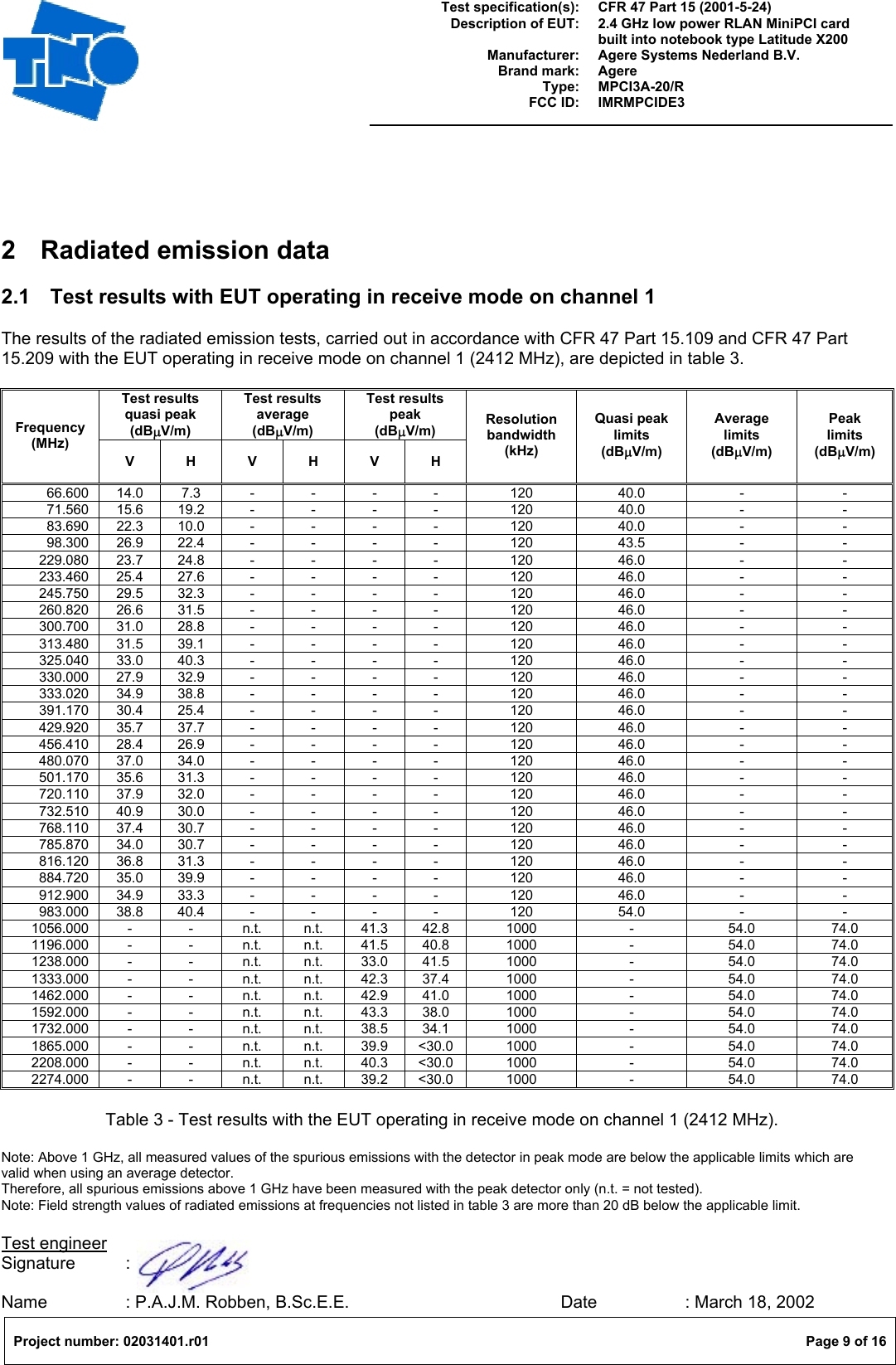
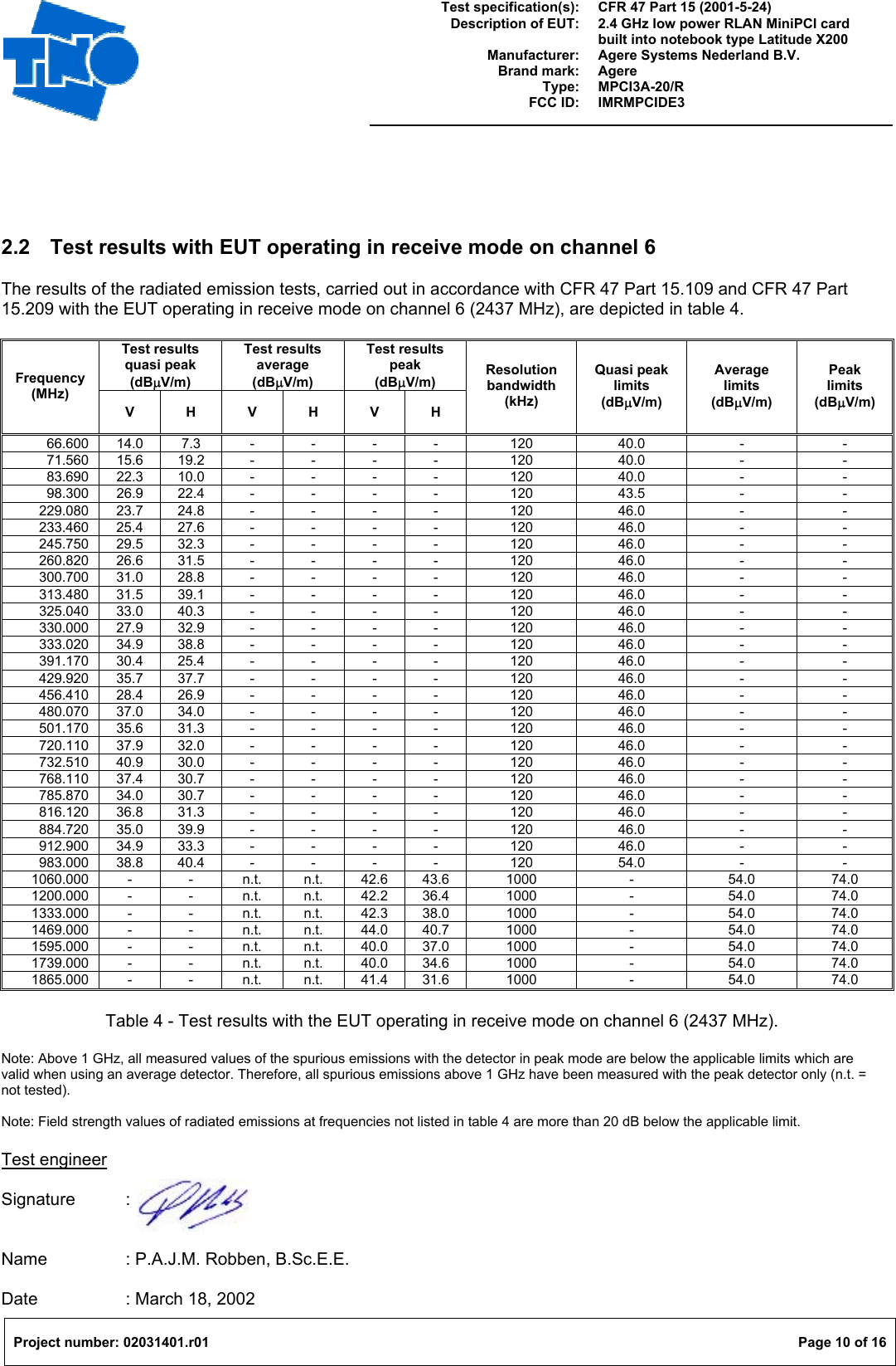
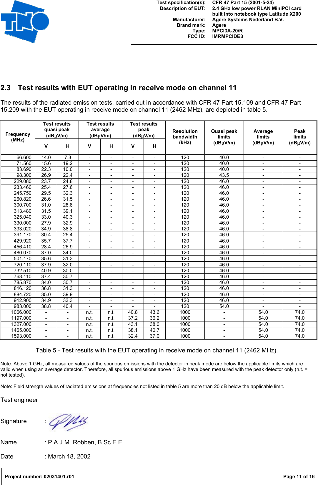
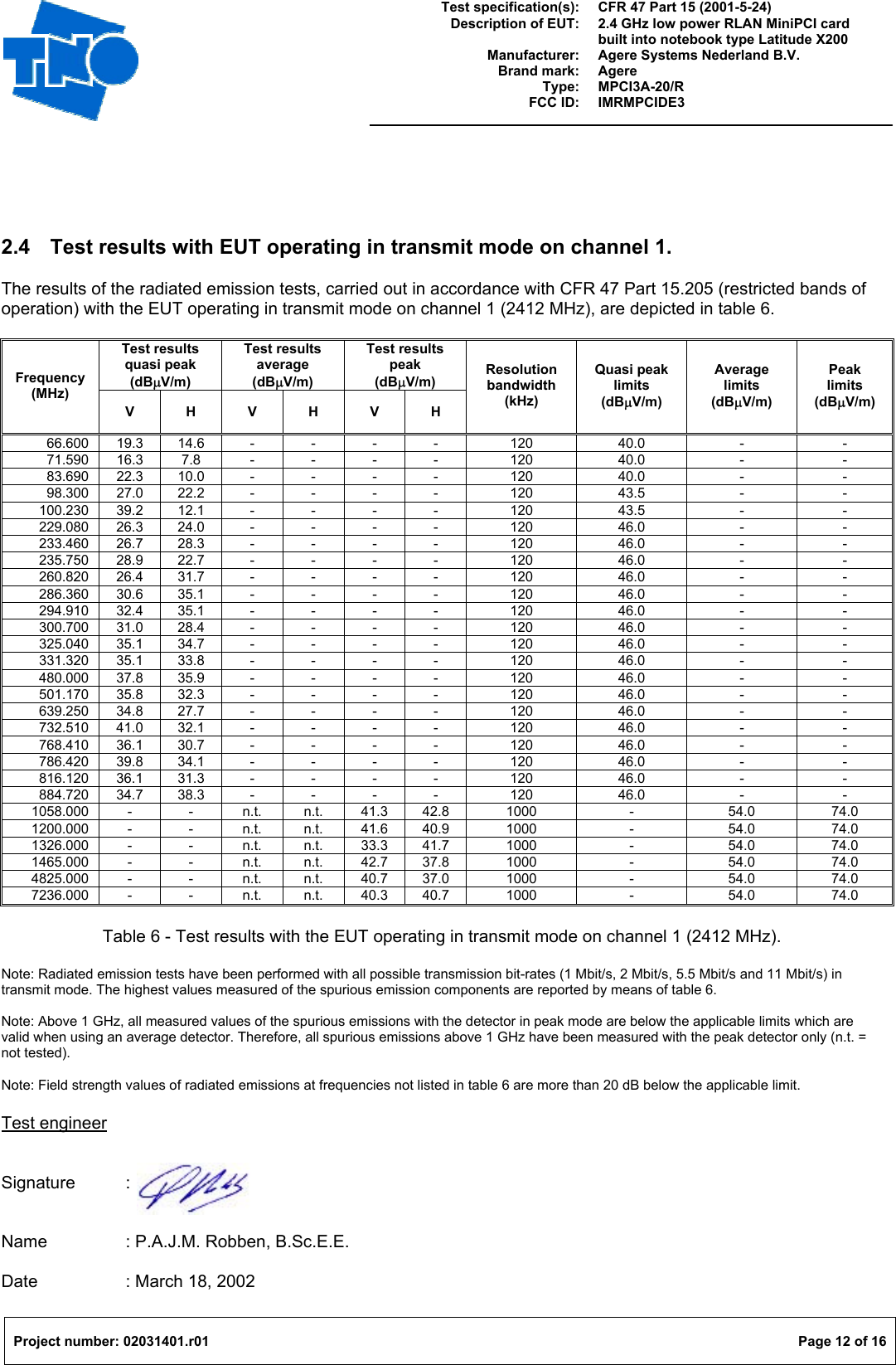
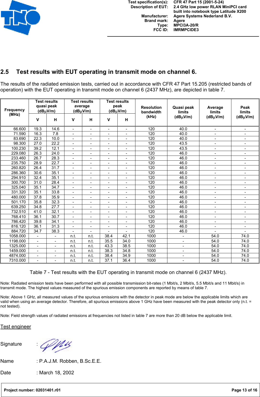
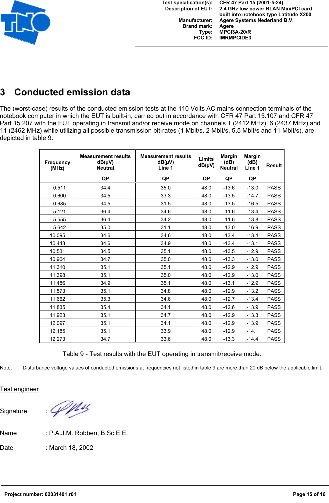
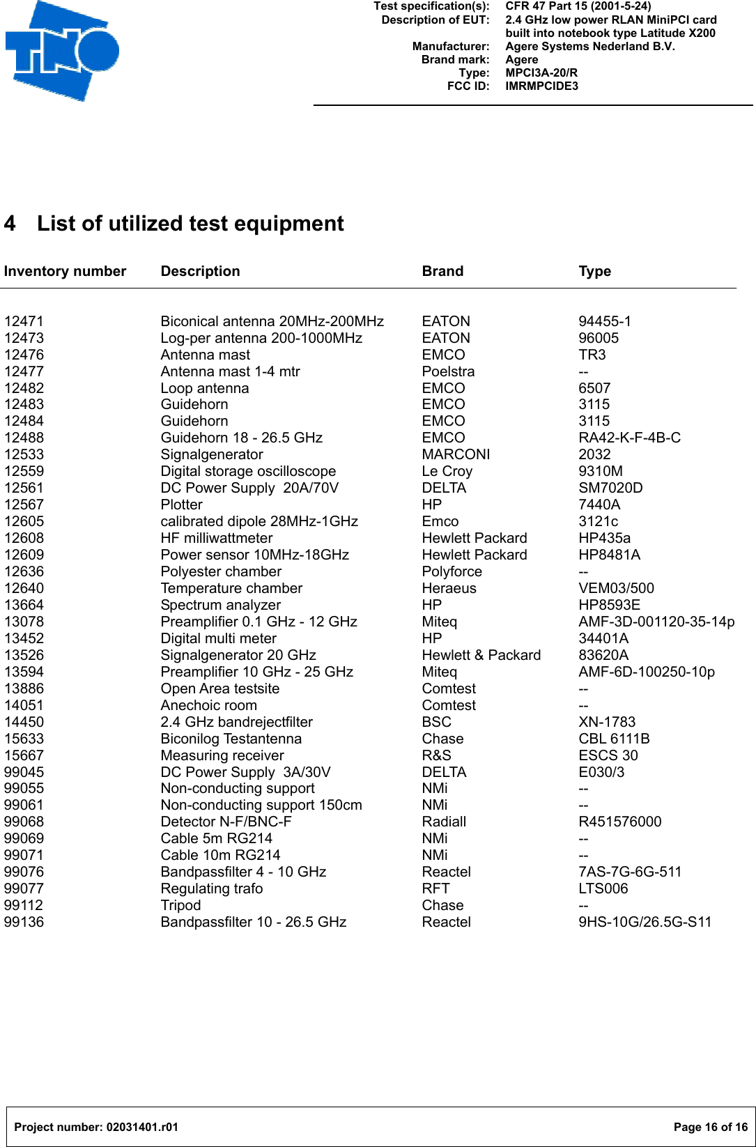
02031401 manual RF Exposure