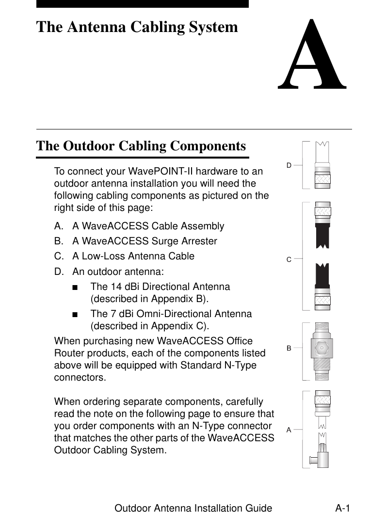
Agere Systems Nederland WLPCE24H WaveLAN IEEE PC Card Turbo 11Mb User Manual Outdoor Antenna Installation Guide

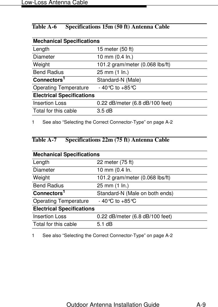
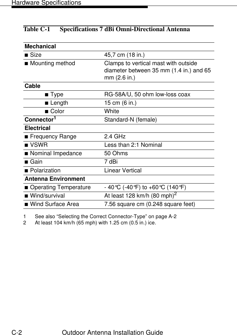
Agere Systems Nederland B.V. WaveLAN IEEE PC Card Turbo 11Mb Outdoor Antenna Installation Guide

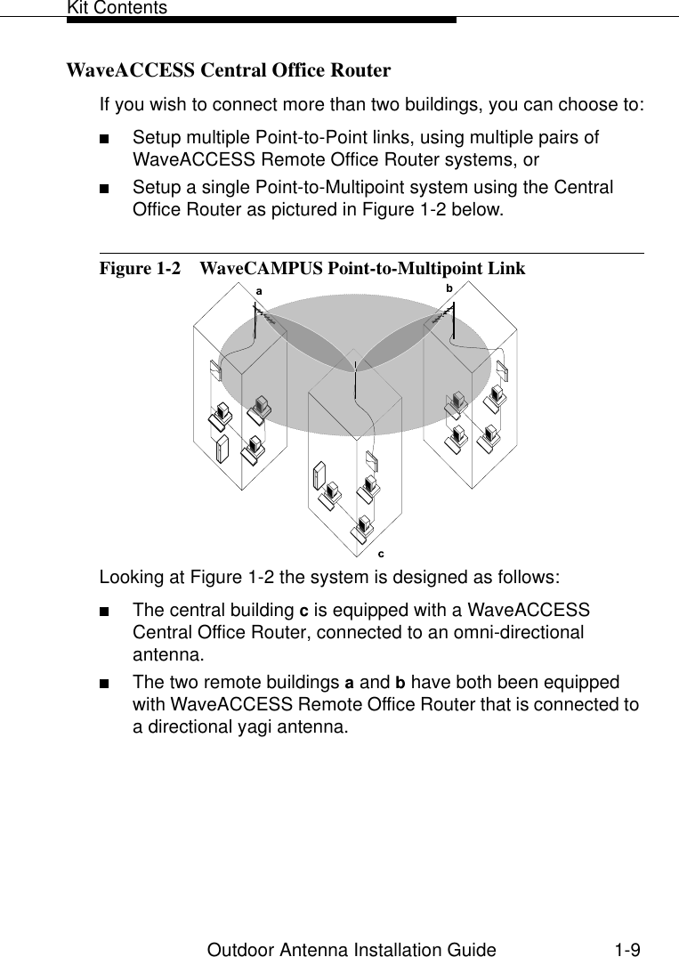
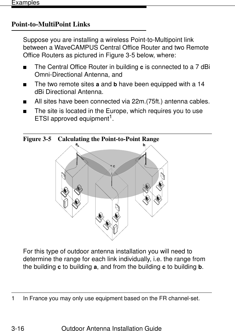
Outdoor antennae guide

Outdoor Antenna Installation Guide;EZI%'')773JJMGI6SYXIV012706/A November 1999Copyright © 1999 Lucent Technologies Inc. All Rights ReservedYou can find the latest software & documentation at:http://www.wavelan.com/supportCOV_ODC.fm  Page 1  Friday, November 5, 1999  2:24 PM
Outdoor Antenna Installation Guide iTable of Contents iWaveLAN Technical Support vRegulatory Information vi1 Welcome 1-1Introducing WaveACCESS Office Router  1-1■About This Guide  1-1■Who Should Use This Guide  1-2■Overview of this Guide  1-3■Finding Additional Information  1-4Kit Contents  1-7■About WaveACCESS Office Router  1-8■About the WaveACCESS PC Card  1-102 Preparing for Installation 2-1Site Prerequisites  2-1Overview of the Indoor Installation  2-3■Selecting the Right WaveACCESS Card  2-4■Placement of the WavePOINT-II Hardware  2-6■Placement of the Surge Arrester  2-8■Antenna Cable Route  2-8Table of Contents
Table of Contentsii Outdoor Antenna Installation GuideTable of ContentsOverview of the Outdoor Installation  2-10■Antenna Placement  2-11■Antenna Mast/Wall Bracket  2-14■Grounding System  2-15■Lucent Technologies Antenna  2-16■Antenna Cable Routing  2-19Before Climbing the Roof...  2-203 Determine Range & Clearance 3-1Introduction  3-1Determine the Outdoor Range  3-2■Determine the Maximum Range  3-3■Determine the Cable Factor  3-8■Determine the Clearance Factor  3-9Examples  3-13■Point-to-Point Links  3-13■Point-to-MultiPoint Links  3-164 Installing the Antenna 4-1Planning Antenna Installation  4-1■Safety Precautions  4-2■Installation Overview  4-5Mounting the Antenna  4-6■Mounting the Directional Antenna  4-6■Mounting the Omni-directional Antenna  4-9Connecting the Antenna Cable  4-11■Sealing the Cable Connectors  4-12
Table of ContentsOutdoor Antenna Installation Guide iiiA The Antenna Cabling System A-1The Outdoor Cabling Components  A-1■Selecting the Correct Connector-Type  A-2WaveACCESS Cable Assembly  A-5WaveACCESS Surge Arrester  A-6Low-Loss Antenna Cable  A-8B 14 dBi Directional Antenna B-1General Description  B-1■Contents of the Antenna Box  B-1C 7 dBi Omni-Directional Antenna C-1Hardware Specifications  C-1Index IX-1List of Figures LOF-1List of Tables LOT-1Warranty Repair Card War-1
v Outdoor Antenna Installation GuideYou can find the most recent software and user documentation for all WaveLAN products on our internet site.If you encounter problems when installing or using this product, or would like information about our other WaveLAN products, please contact your local Authorized WaveLAN Reseller or regional Lucent Technologies Sales Office. Addresses of Resellers and Sales Offices can be found on the WaveLAN website.In case no local or regional support is available, you can reach us at the addresses or telephone numbers listed below.When contacting WaveLAN Support, please complete the WaveLAN Problem Report form and include it with your email or fax. The form (report.txt) is available on the WaveLAN Software CD-ROM, or you can go to the Feedback section of the WaveLAN website and fill out the Problem Report form on-line.Software and DocumentationWorld Wide Web http://www.wavelan.comFTP Server ftp://ftp.wavelan.com/pubWaveLAN Regional SupportU.S.A/ Canada usasupport@wavelan.comCaribbean/ Latin America calasupport@wavelan.comEurope/ Middle-East/ Africa emeasupport@wavelan.comAsia/ Pacific apasupport@wavelan.comWaveLAN Global SupportU.S.A/ Canada Voice: +1 800 WAVELAN - 3Caribbean/ Latin AmericaWaveLAN Technical Support
Outdoor Antenna Installation Guide viTo comply with the regulations listed above, you may only use the Lucent Technologies WaveLAN products, Surge Arrester, Cables and Antennas as described in this document. Each of these WaveACCESS Office Router Kit components must be installed and used in strict accordance with the manufacturer’s instructions. Canada:The products included with the WaveACCESS Office Router kit for outdoor antenna installations comply with RSS 139 of Industry and Science Canada.Europe - EU Declaration of ConformityLucent Technologies declares that the WaveLAN products included with the WaveACCESS Office Router kit conform to the specifications listed below, following the provisions of the EMC Directive 89/336/EEC:■EMC  ETS 300-826 General EMC requirements for Radio equipment.■Radio ETS 300-328 Technical requirements for Radio equipment.USA - Federal Communications Commission (FCC)The devices included with this WaveACCESS Office Router kit comply with Part 15 of FCC Rules. Operation of the devices in a WaveACCESS Office Router system is subject to the following two conditions:■This device may not cause harmful interference.■This device must accept any interference that may cause undesired operation.Interference StatementThis equipment has been tested and found out to comply with the limits for a Class B digital device, pursuant to Part 15 of the FCC rules. These limits are designed to provide reasonable protection against harmful interference in a residential installation. This equipment generates, uses, and can radiate radio frequency energy. If not installed and used in accordance with the instructions, it may cause harmful interference to radio communications. However, there is no guarantee that interference will not occur in a particular installation. If this equipment does cause harmful interference to radio or television reception, which can be determined by turning the equipment off and on, the user is encouraged to try and correct the interference by one or more of the following measures:■Reorient or relocate the receiving antenna.■Increase the distance between the equipment and the receiver.■Connect the equipment to an outlet on a circuit different from that to which the receiver is connected.■Consult the dealer or an experienced radio/TV technician for help.Exposure to Radio Frequency radiation.Antennas shall be mounted in such a manner to minimize the potential for human contact during normal operation. In order to avoid the possibillity of exceeding the FCC radio frequency exposure limits, human proximity to the antenna shall not be less than 20cm (8 inches) during normal operation. Regulatory Information
Regulatory InformationOutdoor Antenna Installation Guide viiInformation to the userWhen connecting WaveLAN devices to other equipment than the Lucent Technologies WaveACCESS Office Router equipment described in this document, the antenna installation may no longer comply with the regulations as defined above. In that case it will be the responsibility of the user to ensure that the entire antenna installation complies with local radio regulations. ■Consult the user documentation that came with the other equipment to determine whether additional instructions or regulations apply.■Verify that the antenna installer is aware of these regulations. In case the device does cause harmful interference with an authorized radio service, the user/operator shall promptly stop operating the device until harmful interference has been eliminated. DisclaimerLucent Technologies is not responsible for any radio or television interference caused by unauthorized modification of the devices included with the WaveACCESS Office Router kit, or the substitution or attachment of connecting cables and equipment other than specified by Lucent Technologies. The correction of interference caused by such unauthorized modification, substitution or attachment will be the responsibility of the user.
Contents1WelcomeIntroducing WaveACCESS Office Router 1-1About This Guide 1-1Who Should Use This Guide 1-2Overview of this Guide 1-3Finding Additional Information 1-4■Installing WavePOINT-II Hardware  1-4■Configuration and Management  1-4■Context-Sensitive Help  1-5■Hardware Specifications  1-5■Additional files on your Software CD-ROM  1-6■Other Sources of Information  1-6Kit Contents 1-7About WaveACCESS Office Router 1-8■WaveACCESS Remote Office Router  1-8■WaveACCESS Central Office Router  1-9■Upgrading WaveACCESS Office Router  1-10About the WaveACCESS PC Card 1-10
Outdoor Antenna Installation Guide 1-11WelcomeIntroducing WaveACCESS Office Router 1Welcome to WaveACCESS Office Router, the easy way to wireless computing. Building your own wireless campus has never been easier.The WaveACCESS Office Router family consists of various dedicated WaveACCESS Office Router kits, that enable you to setup the wireless outdoor antenna link of your choice to connect multiple buildings or LANs.About This Guide 1This Outdoor Antenna Installation Guide explains how to install and set-up an outdoor antenna installation based on WaveACCESS/IEEE Turbo 11 Mb PC Cards that will be used in combination with:■WaveACCESS Office Router  products1■WaveACCESS  Internet Client productsThere is also a chapter about verifying the wireless link quality and correcting problems that might arise during installation or operation.1 Formerly also referred to as WavePOINT-II PTP Bridge, WaveACCESS Link WP-II.
Introducing WaveACCESS Office Router1-2 Outdoor Antenna Installation GuideThis document does not describe the special antennas for WaveACCESS LINK BR132, SM1042 or WaveACCESS NET CU, MDU and SDU products.Although you can use this document as a general reference guide for outdoor antenna placement, you are advised to consult the documentation that came with the dedicated antennas for these products for specific antenna characteristics, regulatory information and installation instructions.Neither does this guide explain how to erect antenna masts, or how to install a safety grounding system. These are pre-requisites that must be in place before the directional antenna is installed.Who Should Use This Guide 1The installation of Outdoor Antenna Links requires technical expertise. At the very least, you should be able to:■Install and configure the network components, such as the WavePOINT-II access point and the WaveACCESS administrator (WaveMANAGER) station.■Understand or have a working knowledge of the installation procedures for network operating systems under Microsoft Windows 95/98 and/or Microsoft Windows NT.■Mount the outdoor antenna and surge arrester. Lucent Technologies recommends that the installation is performed by a qualified antenna installation service.!DANGER:The WaveACCESS Office Router outdoor antennas are intended for mounting on a roof, or the side of a building. Installation shall not be attempted by someone who is not trained or experienced in this type of work.The antenna has to be installed by a suitably trained professional installation technician or a qualified antenna
Introducing WaveACCESS Office RouterOutdoor Antenna Installation Guide 1-3installation service. The site pre-requisites have to be checked by a person familiar with the national electrical code, and other regulations governing this type of installation.Overview of this Guide 1This User’s Guide describes how to extend a Local Area Network (LAN) system with an outdoor antenna link. In this manual you will find information that you will need to prepare or verify the antenna installation. Chapter 1 “Welcome” (This Chapter) 1Introduces the Outdoor Kit and describes where you can find the information you need to set up a wireless system.Chapter 2 “Preparing for Installation” 1Describes the requirements that a site must meet before you start installing the equipment.Chapter 3 “Determine Range & Clearance” 1Describes the how to calculate the typical and/or maximum distance that you can achieve using WaveACCESS Office Router  products.Chapter 4 “Installing the Antenna” 1Describes how to mount the Lucent Technologies antennas to a mast or wall, and how to connect the antenna to the cable and Surge Arrester.
Introducing WaveACCESS Office Router1-4 Outdoor Antenna Installation GuideAppendix A “The Antenna Cabling System” 1Describes the hardware specifications of the certified WaveACCESS Cable Assembly, Surge Arrester and Low-loss Antenna Cable that you will need to connect the WavePOINT-II hardware or other computing device to an outdoor antenna installation.Appendix B “14 dBi Directional Antenna” 1Describes the hardware specifications of this antenna that you can use to set up long-distance point-to-point antenna links.Appendix C “7 dBi Omni-Directional Antenna” 1Describes the hardware specifications of this antenna that you can use to set up wide-range antenna links.Finding Additional Information 1Installing WavePOINT-II Hardware 1WaveACCESS outdoor antenna installations are typically connected to WavePOINT-II devices. The hardware installation of these devices is described in the WavePOINT-II Quick Installation Guide that is included with each WavePOINT-II unit.Configuration and Management  1The configuration and management of outdoor antenna links is controlled via the WaveMANAGER/OR (Office Router) program; an MS-Windows based application that can be installed on almost any computer running Windows 95, 98 or Windows NT (v4.0). How to install this program is described in the WavePOINT-II Quick Installation Guide that is included with each WavePOINT-II unit.
Introducing WaveACCESS Office RouterOutdoor Antenna Installation Guide 1-5How to use this program is described in:■The Context-Sensitive Help described on page 1-5.■The WaveMANAGER/OR User’s Guide provided on the software CD-ROM that came with the WavePOINT-II device (inserted inside the back-side cover of the WavePOINT-II Quick Installation Guide).The WaveMANAGER/OR User’s Guide also describes how to monitor the performance of your wireless network, and provides hints and scenarios for troubleshooting performance degradation.To view and/or print this document, you will need to install the Adobe Acrobat Reader provided on the software CD-ROM.Context-Sensitive Help 1Context-sensitive help for the WaveMANAGER/OR program is available by clicking the “Help” button on the screen or pressing the  function key. Hardware Specifications 1■WavePOINT-II hardware specifications are described in the “WavePOINT-II Quick Installation Guide” that is shipped with each WavePOINT-II device.■Radio Frequency specifications of the WavePOINT-II are described in the Quick Installation Guide of the WaveACCESS/IEEE Turbo 11 Mb PC Card. ■Hardware specifications for the outdoor antennas, the cabling system and the WaveACCESS Surge Arrester are listed in the Appendix of this “Outdoor Antenna Installation Guide”.F1
Introducing WaveACCESS Office Router1-6 Outdoor Antenna Installation GuideAdditional files on your Software CD-ROM  1All software CD-ROM (or diskettes) that come with your WaveACCESS products, include a file called “readme.txt”. This file contains information about the software version and/or drivers on the diskette. You are advised to print and read the “readme.txt” file prior to installing your WaveACCESS products, as it may contain additional information that was not available when this document was printed.Other Sources of Information  1All documentation listed above can be downloaded from the WaveLAN/WaveACCESS website at: HTTP://WWW.WAVELAN.COM. You are advised to visit the website at regular intervals for the latest available information, documentation and software updates and other WaveACCESS news.
Kit ContentsOutdoor Antenna Installation Guide 1-7Kit Contents 1The WaveACCESS Office Router Starter Kit contains the following items:■One WavePOINT-II device, loaded with the dedicated WaveACCESS Office Router router software (see page 1-8).■One WaveACCESS/IEEE Turbo 11 Mb PC Card (see page 1-10).■One Cable Assembly (described in Appendix A).■One WaveACCESS Surge Arrester (described in Appendix A).■One External Antenna for Outdoor use. The External Antenna may either be:■14 dBi directional Yagi antenna (described in Appendix B).■7 dBi omni-directional antenna (described in Appendix C).Each of the items is shipped in dedicated boxes to avoid damage during shipment.Together with this kit you should have received a Lucent Low-loss antenna cable (a separately ordered item) which can either be a:■6 m (20 ft.) cable■15 m (50 ft.) cable■22 m (75 ft.) cableIf any of these items is missing, please contact your authorized WaveLAN/WaveACCESS Reseller or Distributor. You can find the addresses on the WaveLAN/WaveACCESS website at http://www.wavelan.com.
Kit Contents1-8 Outdoor Antenna Installation GuideAbout WaveACCESS Office Router 1The WaveACCESS Office Router is based on a standard WavePOINT-II device that has been loaded with dedicated software to enable you to setup a wireless system that supports:■WaveACCESS Remote Office Router functionality, or■WaveACCESS Central Office Router functionality. WaveACCESS Remote Office Router  1With two WaveACCESS Remote Office Router kits, it’s easy to setup a wireless Point-to-Point link as pictured in Figure 1-1 below.Figure 1-1  Wireless Point-to-Point LinkThe Point-to-Point (PTP) Link functionality enables you to setup a connection between two locations as an alternative to:■Leased lines in building-to-building connections, or ■Wired Ethernet backbones between WavePOINT-II access points in ‘hard-to-wire’ environments.
Kit ContentsOutdoor Antenna Installation Guide 1-9WaveACCESS Central Office Router 1If you wish to connect more than two buildings, you can choose to:■Setup multiple Point-to-Point links, using multiple pairs of WaveACCESS Remote Office Router systems, or■Setup a single Point-to-Multipoint system using the Central Office Router as pictured in Figure 1-2 below.Figure 1-2  WaveCAMPUS Point-to-Multipoint LinkLooking at Figure 1-2 the system is designed as follows:■The central building c is equipped with a WaveACCESS Central Office Router, connected to an omni-directional antenna.■The two remote buildings a and b have both been equipped with WaveACCESS Remote Office Router that is connected to a directional yagi antenna.
Kit Contents1-10 Outdoor Antenna Installation GuideUpgrading WaveACCESS Office Router 1If you wish to extend the features of previously purchased hardware you can purchase dedicated Software License Kits to upgrade:■WavePOINT-II Access Points into one of the WaveACCESS Office Router Routers described on the previous pages.■Extend the features of a previously purchased WaveACCESS Office Router Routers. For more information about the software license upgrade program, please consult:■Your authorized WaveLAN/WaveACCESS Reseller or local Lucent Technologies Sales office for more information. ■The WaveLAN/WaveACCESS website at:HTTP://WWW.WAVELAN.COMAbout the WaveACCESS PC Card 1The WaveACCESS PC Card shipped with the WaveACCESS Office Router Starter kit can be used in any computing device that supports a PC Card Type II slot including the WavePOINT-II bridge.
Kit ContentsOutdoor Antenna Installation Guide 1-11■In FCC regulated countries2, all WaveACCESS Office Router kits will include the standard black-colored WaveACCESS/IEEE Turbo 11 Mb PC Card.■In ETSI regulated countries3, France & Japan, the type of WaveACCESS/IEEE Turbo 11 Mb PC Card will be related to the type of antenna:■WaveACCESS Office Router kits that include a 7 dBi omni-directional antenna, will be shipped with the standard black-colored WaveACCESS/IEEE Turbo 11 Mb PC Card. ■WaveACCESS Office Router kits that include the 14 dBi directional antenna, will be shipped with the red-colored ‘Fixed Wireless System Card’. !CAUTION:When installing an outdoor antenna installation in Europe and/or Japan you must always use the red-colored ‘Fixed Wireless PC Card’ to connect the Lucent Technologies 14 dBi directional antenna to a host device. Failing to comply with these guidelines may be in violation of the local radio regulations and be subject to fines and/or prosecution. It is the responsibility of the end-user to ensure that the antenna installer is aware of these regulations, and that the correct type of card is used to connect a host device to the outdoor antenna installation. Lucent Technologies and its resellers or distributors are not liable for violation of government regulations that may arise from failing to comply with these guidelines.2 Radio regulations as defined by the Federal Communications Commission (FCC) apply in the USA, Canada and most countries in Latin America.3 Radio regulations as defined by the European Telecommunications Standards Institute (ETSI). WaveACCESS PC Cards sold in these countries are identified by the channel-set ETS, FR or JP (printed on the back-side label of the WaveACCESS PC Card).
Contents2Preparing for InstallationSite Prerequisites 2-1Overview of the Indoor Installation 2-3Selecting the Right WaveACCESS Card 2-4Placement of the WavePOINT-II Hardware 2-6Placement of the Surge Arrester 2-8Antenna Cable Route 2-8Overview of the Outdoor Installation 2-10Antenna Placement 2-11Antenna Mast/Wall Bracket 2-14■Tripod Mount  2-14■Wall (Side) Mount  2-14■Antenna Mast Requirements  2-15Grounding System 2-15Lucent Technologies Antenna 2-16■Antenna Alignment  2-17■Antenna Polarization  2-18Antenna Cable Routing 2-19Before Climbing the Roof... 2-20
Outdoor Antenna Installation Guide 2-12Preparing for InstallationSite Prerequisites 2Please review all requirements outlined within the sections listed below before starting the installation procedure:■Overview of the Indoor Installation■Overview of the Outdoor Installation■Verify Before Climbing the Roof...Prior to climbing on the roof or any other area where you intend to install the outdoor antenna, you are advised to:■Verify you have arranged all safety measures for outdoor/rooftop installation.■Verify you have all equipment and tools required to install the outdoor antennas.■Install and verify proper operation of the equipment.!WARNING:Carefully plan the day for your antenna installation. Do not install the antenna in wet or windy conditions, during a thunderstorm, or when the area where the equipment will be installed is covered with ice and/or snow.
Site Prerequisites2-2 Outdoor Antenna Installation Guide!DANGER:The WaveACCESS Office Router outdoor antennas are intended for mounting on a roof, or the side of a building. Installation shall not be attempted by someone who is not trained or experienced in this type of work.The antenna has to be installed by a suitably trained professional installation technician or a qualified antenna installation service. The site pre-requisites have to be checked by a person familiar with the national electrical code, and other regulations governing this type of installation.
Overview of the Indoor InstallationOutdoor Antenna Installation Guide 2-3Overview of the Indoor Installation 2To setup a point-to-point wireless connection, you will need:■Two WaveACCESS Office Router Kits, and ■Two Low-loss antenna cables.Figure 2-1 shows an overview of the hardware setup for the indoor installation.Figure 2-1  Overview Indoor InstallationOn each end of the wireless link you will need:A. A WaveACCESS IEEE adapter card (see “Selecting the Right WaveACCESS Card” on page 2-4).B. A WavePOINT-II device that has been loaded with WaveACCESS Office Router Router software.C. The Cable Assembly to connect the WaveACCESS IEEE adapter card (A) to the Surge Arrester.D. A surge arrester to protect your sensitive WaveACCESS equipment from static discharge and transients that may occur to your antenna.E. A low-loss antenna cable to connect the indoor installation to the outdoor antenna.
Overview of the Indoor Installation2-4 Outdoor Antenna Installation Guide!WARNING:The WaveACCESS Office Router, the WaveACCESS Surge Arrester and the antenna mast must be connected to the same grounding system as described in “Grounding System” on page 2-15.Selecting the Right WaveACCESS Card  2Wireless communications are usually subject to local radio regulations, where additional regulations may apply to outdoor antenna communications. To comply with such regulations, Lucent Technologies offers two types of WaveACCESS Cards, that can be used to connect a WavePOINT-II or other computing device to an outdoor antenna installation:■In countries that adhere to the FCC regulations1, you can use the standard black-colored WaveACCESS IEEE 802.11 card.■In countries that adhere to the ETSI regulations2, France and Japan, you must select the card-type based upon the antenna that will be used:■You can use the black-colored WaveACCESS IEEE 802.11 card when connecting the device to standard Lucent 7 dBi omni-directional antennas. ■You must use the red-colored IEEE Fixed Wireless PC Card when connecting the device to the standard Lucent 14 dBi directional antenna for outdoor use.When you order a WaveACCESS Office Router kit for outdoor antenna installations, the kit marketed in your country will include 1 As defined by the US Federal Communications Commission (FCC)2 As defined by the European Telecommunications Standards Institute (ETSI)
Overview of the Indoor InstallationOutdoor Antenna Installation Guide 2-5the correct card type that complies with the regulations that apply in your country.When you order the WaveACCESS outdoor antenna equipment as separate components, make sure that you order the correct product items. In case you are not certain about the regulations that apply in your country, consult your local Lucent Technologies Sales Office. !WARNING:At all times, it will be the responsibility of the end-user to ensure that an outdoor antenna installation complies with local radio regulations. The end-user must verify that:■The antenna installer is aware of these regulations.■The correct type of WaveACCESS card is used to connect the host device to the outdoor antenna installation.■The correct type of cables and surge arrester have been used, according to the instructions described in this document.Lucent Technologies and its resellers or distributors are not liable for any damage or violation of government regulations that may arise from failing to comply with these guidelines.
Overview of the Indoor Installation2-6 Outdoor Antenna Installation GuidePlacement of the WavePOINT-II Hardware 2The WavePOINT-II hardware of your WaveACCESS Office Router device is designed for indoor mounting and operation. The ideal location to install your WavePOINT-II unit must satisfy the following requirements:■The location provides a connection to a grounding type AC wall outlet (100-240 VAC), using the standard power cord as supplied with the unit. The ground of the AC wall outlet must be connected to the same grounding system as the WaveACCESS Surge Arrester and antenna mast (see “Grounding System” on page 2-15).■The location must allow for easily disconnecting the WavePOINT-II unit from the AC wall outlet.■The location provides a connection to the network backbone that may either be:■An Ethernet LAN cable that connects it to a hub, bridge or directly into a patch panel■A WaveACCESS wireless connection via a second WaveACCESS card that is inserted into the other PC Card slot of the WavePOINT-II device.■The location is as close as possible to the point where the antenna cable will enter the building (see also “Placement of the Surge Arrester” on page 2-8).!CAUTION:The WaveACCESS Office Router is designed for indoor installations. At all times the location of the WavePOINT-II unit must be indoors, to protect the unit from extreme weather conditions, excessive heat and humidity and to keep the unit free from vibration and dust.
Overview of the Indoor InstallationOutdoor Antenna Installation Guide 2-7Prior to mounting the WavePOINT-II unit you are advised to, carefully calculate:■The distance between the intended location of your WavePOINT-II unit and the location of the antenna mast, and■The height of the antenna on the mast.If the low-loss antenna cable that came with your kit is not long enough to cover this distance you can select from the following two options:■Select another cable length from the Lucent Technologies low-loss cable offering (see Appendix A ”The Antenna Cabling System”), or■Select another location that satisfies the requirements listed on the previous page to mount your WavePOINT-II device.As the length of the antenna cable may affect the actual range of your outdoor antenna installation, the second one is the preferred option. !WARNING:You are not allowed to change the length of the Lucent Technologies low-loss antenna cable. Shortening the cable will void the Lucent Technologies Warranty, and may conflict with radio certifications and/or approvals.How to install the WavePOINT-II hardware is described in the “WavePOINT-II Quick Installation Guide” that was shipped with the WavePOINT-II device.
Overview of the Indoor Installation2-8 Outdoor Antenna Installation GuidePlacement of the Surge Arrester 2The WaveACCESS Surge Arrester is an indispensable part of your outdoor antenna installation, to protect your sensitive electronic equipment from transients or electro-static discharges at the antenna.For optimal protection the WaveACCESS Surge Arrester must be installed at a location that satisfies the following requirements:■A location as close to the location where the antenna cable will enter the building (see also “Placement of the WavePOINT-II Hardware” on page 2-6).■The location allows for easily (dis-)connecting the surge arrester from/to the WaveACCESS adapter card in the WaveACCESS Office Router using the Cables Assembly pictured in Figure 2-1 on page 2-3. ■The location provides a connection to the same grounding system as the WavePOINT-II unit and the outdoor antenna mast as described in “Grounding System” on page 2-15.Antenna Cable Route 2The antenna cable must be connected to the WavePOINT-II unit via the WaveACCESS Surge Arrester and Cable Assembly as pictured in Figure 2-1 on page 2-3. To plan the route of the antenna cable please consider the following:■Does the cable route require drilling through a wall or ceiling?■Do you have a building plan of the desired location showing any other existing cabling routes like electricity, telephone or networking?■Does the type of building materials require special tools for drilling purposes?
Overview of the Indoor InstallationOutdoor Antenna Installation Guide 2-9The cable should not be installed into “tight” positions, as bending or applying excessive force to the connectors may damage the antenna cable. Always allow the cable to bend naturally around corners. The recommended bend radius is 25 mm (1 in.). The antenna cable must be secured along its complete length. No part of the antenna cable should be allowed to hang free. This is particularly important for cable parts that are installed outdoors. !CAUTION:The antenna cable and cable connectors are not designed to withstand excessive force:a. Do not use the connectors as “cable grips” to pull cable through raceway or conduit.b. Do not use the cable connector to support the weight of the cable during or after installation.c. Do not use any appliances to tighten the connectors.d. Always seal the connectors using the water-proofing tape that is included with your Outdoor Kit.Prior to sealing the outdoor connectors and permanently securing the cable to the wall using cable ties and wall hooks, you may wish to verify if the installation and all components function properly.
Overview of the Outdoor Installation2-10 Outdoor Antenna Installation GuideOverview of the Outdoor Installation 2The outdoor installation of the link (point-to-point or point-to-multipoint) will consist of the following components:■The Lucent Technologies Antenna■The Lucent Technologies proprietary low-loss antenna cable (available in different cable lengths).■Antenna Mast/Wall Bracket for the antenna (not included with kit).■An adequate Grounding System that meets the requirements described on page 2-15.NOTE:All outdoor cable connectors must be sealed with the enclosed weather-proofing stretch tape to permanently waterproof the coax connectors. !DANGER:For your own safety, the antenna mast and the grounding system should be installed only by experienced installation professionals who are familiar with local building and safety codes and/or the national electrical codes. Carefully read the instructions as described for the “Grounding System” on page 2-15 and verify that your installation complies with the appropriate regulations and codes before installing the antenna.
Overview of the Outdoor InstallationOutdoor Antenna Installation Guide 2-11Antenna Placement 2To achieve maximum performance for your wireless outdoor connection, the WaveACCESS Outdoor Antennas must have clear line-of-sight. Line-of-sight can be defined as:■No obstacles in the direct path between the two antennas. ■No obstacles within a defined zone around the antenna beam.You need to be aware that the shape of a radio beam is not straight and narrow like a laser beam. The radio beam, also referred to as Fresnel Zone3, is rather “bulged” in the middle, like for example a “rugby ball”. The exact shape and width of the Fresnel Zone is determined by the path length and frequency of the radio signal.If any significant part of this zone is obstructed, a portion of the radio energy will be lost, resulting in reduced performance. Reduced performance may also occur when obstacles that are close to the antenna beam cause signal reflections or noise that interfere with the radio signal.Figure 2-2 shows some typical examples of obstacles that you must avoid for the Directional Antenna to operate effectively:A. Neighboring BuildingsB. Trees or other obstructionsC. Power linesTo allow optimal performance you will need to ensure that the type and placement of the antennas leaves sufficient clearance of the Fresnel Zone at the maximum width of the bulge, typically at the mid-point between the antennas. For more information turn to Chapter 3 ”Determine Range & Clearance”.3Pronounced as “Fray-Nell”
Overview of the Outdoor Installation2-12 Outdoor Antenna Installation GuideFigure 2-2  Potential Obstacles for a Directional AntennaTo minimize the influence of obstacles, signal interference or reflections please note the following guidelines:■Mount the antenna as high as possible above the “ground” to allow maximum clearance:■In open areas “ground” is the actual surface of the earth■In dense urban areas “ground” is to be interpreted as the height of the highest obstacle in the signal path between the two antenna sites. ■Avoid trees in the signal path to avoid interference or signal absorption due to dynamic changes in seasons (leaves/ice).■Install the antenna at least 2 m (6 ft) away from all other antennas.Other situations where reflections of the radio signal may cause interference are environments where large reflecting surfaces exist in parallel or partly perpendicular to the antenna beam.
Overview of the Outdoor InstallationOutdoor Antenna Installation Guide 2-13Environments with large reflective surfaces include:■Mirrored-glass buildings ■Crowded parking lots ■Water or moist earth and moist vegetation■Above ground power/telephone linesWeather conditions such as rain or snow usually will not have much impact on the performance of your WaveACCESS Outdoor System, provided that you sealed all cable connectors using the weather-proofing tape. Seasonal factors that could have an effect on signal propagation may occur in the following situations: ■A marginal communications quality in late fall (with no leaves on trees in the signal path) might fail in the summer.■In winter, an antenna link may fail when the antenna is exposed to ice buildup, or when the antenna elements are covered with snow. In these cases consult your supplier to take appropriate steps to maintain or optimize wireless performance.
Overview of the Outdoor Installation2-14 Outdoor Antenna Installation GuideAntenna Mast/Wall Bracket 2Basically there are two ways to erect an antenna mast:■Tripod Mount■Wall (Side) MountTripod Mount 2The tripod mount is used primarily on peaked and flat roofs. The antenna mast must be secured to the roof using 3 or 4 guy wires that are equally spaced around the mast. When the height of the antenna mast is more than 3 meters (10 ft), you are advised to use at least three guy wires for each 3 meter (10 ft) section of the mast. Wall (Side) Mount 2A wall (side) mount allows for mounting an antenna (mast) on the side of a building or on the side of an elevator penthouse. This will provide a convenient mounting location when the roof overhang is not excessive and/or the location is high enough to provide a clear line of sight.■When you are installing the 14 dBi Directional Antenna, you can mount the antenna directly to the wall, if the mounting location allows you to aim the antenna to the opposite end of the antenna link.■When you are installing the 7 dBi omni-directional antenna, you will need to mount a special antenna mast using dedicated wall brackets for the mast.
Overview of the Outdoor InstallationOutdoor Antenna Installation Guide 2-15Antenna Mast Requirements 2To accommodate the WaveACCESS antennas, the antenna mast must satisfy the following requirements:a. The construction of the mast must be of a sturdy, weatherproof and non-corrosive material like for example galvanized or stainless steel construction pipe.b. Diameter of the mast should be between 29 mm (1.125 in.) and 41 mm (1.625 in.).c. The height of the antenna mast must be sufficient to allow the antenna to be installed at least 1.5 m (5 ft.) above the peak of roof. If the roof is metal, then the height of the antenna should be a minimum of 3 m (10 ft) above the roof (see also Chapter 3 ”Determine Range & Clearance”).d. The mast or wall-bracket must be free from any substance that may prevent a good electrical connection with the antenna; for example, paint. Grounding System 2Direct grounding of the antenna mast, WaveACCESS Office Router bridge and WaveACCESS Surge Arrester is very important. A safety grounding system is necessary to protect your WaveACCESS Outdoor installation from lightning strikes and the build-up of static electricity.!WARNING:The antenna mast, WaveACCESS Office Router and WaveACCESS Surge Arrester must be connected to the same ground, using an equipotential bonding conductor.A good electrical connection should be made to one or more ground rods, using at least a 10AWG ground wire and non-corrosive hardware. The grounding system must
Overview of the Outdoor Installation2-16 Outdoor Antenna Installation Guidecomply with the National Electrical Code and safety standards that apply in your country. Always check with a qualified electrician if you are in doubt as to whether your WaveACCESS Outdoor installation is properly grounded.Lucent Technologies Antenna 2The Spread Spectrum Technology of the WaveACCESS radio requires high gain antennas. ■The 14 dBi Directional Antenna is a Yagi antenna that has been designed to provide a maximum gain for your outdoor solution while still allowing for ease of use and installation of your outdoor equipment.■The 7 dBi Omni-Directional Antenna is a pole-type antenna that has been designed to provide a wide range radio beam to allow easy alignment of antennas.Another antenna type for outdoor usage is the Lucent Technologies 5 dBi Vehicle Mount Antenna. This omni-directional antenna is typically used for mobile wireless clients such as fork-lift trucks. Together with the high sensitivity of the WaveACCESS radios, these antennas provide the best solution to cover high-speed wireless point-to-point and point-to-multipoint links (see also Chapter 3 ”Determine Range & Clearance”).!WARNING:You are not allowed to connect WaveACCESS devices to any other outdoor antenna than the Lucent Technologies antennas described above. Using different antennas may:■Void Warranty for your WaveACCESS products.■Be in violation of local radio regulations.
Overview of the Outdoor InstallationOutdoor Antenna Installation Guide 2-17It will be the responsibility of the end-user to ensure that an outdoor antenna installation complies with local radio regulations. Lucent Technologies is not liable for any damage or violation of government regulations that may arise from failing to comply with these guidelines.Antenna Alignment 2For optimal performance of your wireless link, make sure that the antennas are properly aligned (facing one another “eye-to-eye”). To align the antennas:■Use a pair of binoculars and/or a map of the area and compass to point the antennas to one another.■Use the Wireless Link Test option of the WaveMANAGER/OR tool as described in the WaveMANAGER/OR User’s Guide to analyze the radio link quality. The Wireless Link Test option will enable you to display the strength of the WaveACCESS radio signal related to the noise that may be appear in the signal path.Looking at the Wireless Link Test screen, you can interactively optimize antenna alignment if required, by making small modifications in the antenna orientation.■Alternatively, consult a professional Antenna Installation Service to optimize the antenna alignment.Omni-directional antennas are characterized by a wide radiation pattern. Therefore alignment of this type of antennas is less critical than for directional antennas.
Overview of the Outdoor Installation2-18 Outdoor Antenna Installation GuideFigure 2-3  WaveMANAGER/OR Wireless Link TestAntenna Polarization 2The standard mounting method for Lucent outdoor antennas is designed for vertical polarization. In some cases you might consider mounting the antenna for horizontal polarization. For example to minimize the influence of cross-talk between antennas when:■You plan to mount multiple directional antennas to the same mast. ■Your wireless link “crosses” another radio beam from a neighboring installation.Mounting for horizontal polarization is only supported by the Lucent 14 dBi Directional Antenna. ■For vertical polarization, the arrow on the protective casing of the 14 dBi Directional Antenna must be pointing upwards.
Overview of the Outdoor InstallationOutdoor Antenna Installation Guide 2-19■For horizontal polarization, the arrow on the protective casing of the 14 dBi Directional Antenna must be pointing left or right.It does not matter what type of polarization you choose, as long as the antennas at both ends of the communications link have been mounted in the same polarity. NOTE:When mounting antennas using different polarization options, always verify that the polarization on both ends of the dedicated links are the same.Antenna Cable Routing 2The antenna cable must be routed and fixed in such a way to clear the passage area for installation technicians. All connectors that are located outdoors, must have a weatherproof seal. You are advised to seal connectors only after you have completed final radio tests.
Before Climbing the Roof...2-20 Outdoor Antenna Installation GuideBefore Climbing the Roof... 2Please consult Chapter 3 ”Determine Range & Clearance” to verify whether you have the correct type of antennas and sufficient clearance in the signal path to cover the distance between the two sites that you wish to connect via the wireless link. Before you start installation, also check the contents of your outdoor kit. If there are signs of shipment damage, or if any of the items are missing, please inform your supplier.Use the following list of items to identify the WaveACCESS Outdoor Kit components and check that you have all the items required:1. WavePOINT-II device loaded with WaveACCESS Office Router software.2. WaveACCESS adapter card.3. WaveACCESS Cable Assembly (to connect item 2 to item 4).4. WaveACCESS Surge Arrester.5. Lucent Technologies low-loss antenna cable (see Note below).6. WaveACCESS Outdoor AntennaDepending on the kit you ordered this could be either the:■14 dBi Directional Antenna.■7 dBi Omni-Directional Antenna.7. Weather-proofing electrical tape. 8. This Outdoor Antenna Installation Guide (this document).NOTE:Not included in the box, but shipped together with your WaveACCESS Office Router kit, you should have received a low-loss antenna cable. Depending on your order, you would have received either a 6 m (20 ft.), 15 m (50 ft.) or a 22 m (75 ft.) cable. Consult Appendix A ”The Antenna Cabling System” for more detailed information.
Contents3Determine Range & ClearanceIntroduction 3-1Determine the Outdoor Range 3-2Determine the Maximum Range 3-3■Type of Outdoor Antenna Equipment  3-4■Data Speed of the Wireless Link  3-7Determine the Cable Factor 3-8Determine the Clearance Factor 3-9Examples 3-13Point-to-Point Links 3-13■Calculate the Clearance effect on Range  3-14■Calculate the Cable effect on Range  3-15Point-to-MultiPoint Links 3-16
Outdoor Antenna Installation Guide 3-13Determine Range & ClearanceIntroduction 3When you read about wireless outdoor products, you will often encounter the terms “output power” of the radio and “gain” of the antenna equipment as measures for the “strength” of the transmitted signal. ■Output Power of radio equipment is often subject to maximum limits as defined by local radio regulations. Consequently Output Power is not by definition the way to enhance wireless performance.■High gain antennas are larger in size than low gain antennas, and are characterized by a narrow “focus” of the radio beam. These two characteristics make it more difficult to aim the antennas, and/or adjust antenna alignment to optimize the performance of the wireless point-to-point link.The Lucent Technologies outdoor solution is based upon the following principles:■An output power and antenna gain that comply with the maximum limits as defined by local governing bodies concerning radio transmissions.■Enhanced radio sensitivity for optimal receive quality of WaveLAN radio signals transmitted by remote antennas.In other words: instead of having transmitting radios “scream out louder”, Lucent Technologies WaveLAN devices are designed with “better ears” to listen more carefully.
Determine the Outdoor Range3-2 Outdoor Antenna Installation GuideDetermine the Outdoor Range  3The range of your outdoor antenna installation is closely related to a number of different factors. To allow you to determine the range of the WaveACCESS Office Router antenna system in your situation, we have defined the formula listed below: Range = Maximum Range x Cable Factor x Clearance Factor■Maximum Range identifies the theoretical maximum that could be achieved under optimal circumstances using the available WaveLAN Outdoor products according to their specs and in compliance with local radio regulations.This value can be read from Table 3-1 or Table 3-2, according to the country where the antenna system will be installed.■Cable Factor identifies a corrective percentage value that compensates additional cable loss in case you are using different cable lengths. The Cable Factor value can be read from Figure 3-1 on page 3-9.■Clearance Factor identifies a corrective percentage value that should be applied in case the signal path of your wireless link does not provide the minimum clearance listed in the Maximum Range table. The Clearance Factor can be read from Figure 3-3 on page 3-12.An example on how to use this formula is described on page 3-13.!CAUTION:This formula should only be used as a rule of thumb to asses the possible range that could be achieved in your situation, and/or to select the type and height of the antenna installations. Always perform on-site measurements to validate the results from the range calculation. To perform such measurements you can use the WaveMANAGER/OR Wireless Link test option as described in the WaveMANAGER/OR User’s Guide.
Determine the Outdoor RangeOutdoor Antenna Installation Guide 3-3Determine the Maximum Range 3The maximum range of your WaveACCESS Office Router antenna system is based on the:■Type of Outdoor Antenna Equipment■Data Speed of the Wireless Link (see page 3-7).■Clearance of the Signal Path (see page 3-9). NOTE:The values listed in this section are based upon calculations that assume “optimal radio conditions”. They do not represent a guarantee that the same maximum distance can be achieved at your location. Different performance figures may result from: ■Incorrect alignment of antennas (see page 2-17).■Sources of interference or unexpected reflections in the signal path that affect the communications quality (see “Antenna Placement” on page 2-11).■Severe weather conditions such as heavy rain or snow fall, or strong winds.■Seasonal influences such as leaves on trees, or icing on the antennas.When selecting equipment for an outdoor antenna link make sure that your selection will include an extra safety margin for the maximum range of 100 m (300 ft) or more.
Determine the Outdoor Range3-4 Outdoor Antenna Installation GuideType of Outdoor Antenna Equipment 3As described in the previous chapters, Lucent Technologies offers different types of outdoor antennas, and cable lengths to design your WaveACCESS Office Router outdoor antenna installation.■The 14 dBi Directional Antenna provides maximum range, but due to its narrow signal beam, requires precise antenna alignment to achieve optimal performance.This antenna is typically used in combination with Remote Office Routers to setup a Point-to-Point link, or connect a Remote Office Routers to a Central Office Router.■The 7 dBi Omni-Directional Antenna, provides a wide angle signal beam which makes antenna installation very easy. This ease of installation, compensates for the smaller range that can be achieved with this type of antenna.This antenna is typically used in combination with Central Office Routers to setup a Point-to-Multipoint link.The length of the antenna cable also has an impact on the maximum range that can be achieved with the antenna combination. For information about the effect of antenna cables, please consult the section “Determine the Cable Factor” on page 3-8.Outdoor antenna installations are also subject to local radio regulations that in a number of countries limit the maximum output power. To comply with such regulations, Lucent Technologies offers different outdoor antenna products in the various countries over the world. Therefore you will need to consult the table that matches the radio regulations as apply in your country:■Table 3-1 on page 3-5, for the USA and Canada and any other country that adheres to the radio regulations as defined by the US Federal Communications Commission (FCC).■Table 3-2 on page 3-5, for all European countries, Japan, and any other country that adheres to the radio regulations as defined by the European Telecommunications Standards Institute (ETSI) and MPT.
Determine the Outdoor RangeOutdoor Antenna Installation Guide 3-5Table 3-1   Outdoor Range for FCC ProductsNOTE:The values listed for ETSI countries, France & Japan in Table 3-2 are based on the correct use of the low-power Fixed Wireless PC Card in compliance with ETSI radio regulations (see also “Selecting the Right WaveACCESS Card” on page 2-4). Table 3-2   Outdoor Range for ETSI, FR & JP ProductsAntenna Type 14 dBi Yagi 7 dBi OmniTransmit Rate Range Clearance Range Clearance14 dBi Yagi Low Speed 15.8 km. 20.3 m. 7.1 km. 11.3 m.9.7 mi. 66.8 ft. 4.3 mi. 37.2 ft.Standard Speed 11.2 km. 15.4 m. 5.0 km. 9.1 m.6.9 mi. 50.7 ft. 3.1 mi. 29.9 ft.Medium Speed 7.9 km. 12.1 m. 3.5 km. 7.5 m.4.8 mi. 39.8 ft. 2.1 mi. 24.7 ft.High Speed 5.6 km. 9.8 m. 2.5 km. 6.3 m.3.4 mi. 32.2 ft. 1.5 mi. 20.7 ft.Antenna Type 14 dBi Yagi 7 dBi OmniTransmit Rate Range Clearance Range Clearance14 dBi Yagi Low Speed 11.4 km. 11.3 m. 5.1 km. 7.1 m.7.1 mi. 37.2 ft. 3.2 mi. 23.4 ft.Standard Speed 8.0 km. 9.1 m. 3.5 km. 5.9 m.5.0 mi. 29.9 ft. 2.2 mi. 19.4 ft.Medium Speed 5.6 km. 7.5 m. 2.6 km. 4.9 m.3.5 mi. 24.7 ft. 1.6 mi. 16.1 ft.High Speed 4.0 km. 6.3 m. 1.8 km. 4.1 m.2.5 mi. 20.7 ft. 1.1 mi. 13.5 ft.
Determine the Outdoor Range3-6 Outdoor Antenna Installation GuideAll values listed in Table 3-1 and Table 3-2 apply to antenna installations where:■Antennas have been mounted for vertical polarization (being the default mounting method).■On both ends of the wireless link the maximum length of the antenna cable is 6 m./15ft., and ■The clearance of the signal path (both horizontally and vertically) is equal or better than the listed value in the grey-shaded column.If you are using different cabling lengths and/or the clearance in your environment is less than the minimum identified in the grey-shaded columns, you will need to calculate the actual range for your environment using the formula listed on page 3-2. To do so please consult:■“Determine the Cable Factor” on page 3-8, and/or■“Determine the Clearance Factor” on page 3-9.
Determine the Outdoor RangeOutdoor Antenna Installation Guide 3-7Data Speed of the Wireless Link 3By default, the radio of WaveACCESS Office Router products will always try to transmit at the highest available transmit rate. As data transmissions at lower speeds can travel larger distances than transmissions at the highest transmit rates, the WaveACCESS Office Routers have been designed to apply an “Automatic Transmit Select” mechanism. If for example a data communication fails as a result of an out-of-range situation, the WaveACCESS Office Router will automatically switch to a lower data rate to retransmit the lost message(s).NOTE:Numerous retransmissions may slow down the throughput performance of your wireless outdoor antenna link.If the actual distance between both ends of the wireless link exceeds the maximum range listed for the highest transmit rates, you may wish to tune the “Automatic Transmit Rate” of your WaveACCESS Office Router equipment to avoid unsuccessful transmission attempts at the highest data rate.To help you to determine the appropriate tuning settings, we have listed the range values that apply to the various transmit rates in Table 3-1 and Table 3-2.
Determine the Outdoor Range3-8 Outdoor Antenna Installation GuideDetermine the Cable Factor 3The range value calculations listed in Table 3-1 and Table 3-2 were based on antenna installations where both antennas were connected to a 6m/15 ft. cable. ■If this is the case in your situation, the Cable Factor for your installation is 100%.■If you are using different cables, you will need to determine the Cable Factor as described below, to calculate the probable range for your WaveACCESS Office Router installation.You can use Table 3-3 in combination with Figure 3-1 on page 3-9 to determine which Cable Factor applies to the cabling systems applied in your installation. NOTE:As the Cable Factor value of the 15m.(50ft.) equals the value for 6m. (20ft.) cables, Table 3-3 does not include separate listings for combinations with 15m.(50 ft.) cables.Table 3-3   Antenna Cabling CombinationsCombination  This Location Remote LocationA6m. (15 ft.) 6m. (15 ft.)B6m. (15 ft.) 22m. (75 ft.)C22m. (75 ft.) 22m. (75 ft.)
Determine the Outdoor RangeOutdoor Antenna Installation Guide 3-9Figure 3-1  Cable Factor DiagramDetermine the Clearance Factor 3For optimal performance of your outdoor antenna link, it is important that the signal path between the two WaveACCESS Office Routers provides sufficient clearance.NOTE:A wireless outdoor antenna link that lacks sufficient clearance will suffer from poor performance, which is typically perceived as slow network response times. Although your WaveACCESS Office Router equipment will automatically retransmit every data frame that got lost due to an out-of-range situation or frame collision, the larger the number of retransmissions attempts, the lower the throughput efficiency of your wireless link.This section will explain how to determine the clearance that applies in your environment, and (if applicable) the effect of insufficient clearance on the range of your outdoor antenna link.In Chapter 2 ”Preparing for Installation” we described the shape of the radio beam being “bulged” in the middle, as pictured in Figure 3-2 on page 3-10 below.
Determine the Outdoor Range3-10 Outdoor Antenna Installation GuideFigure 3-2  Fresnel ZoneIf any significant part of this bulged zone is obstructed, a portion of the radio energy will be lost, which may affect the performance of your wireless link in terms of maximum range and/or transmit rate.Looking at Figure 3-2 you will see two variables that determine the shape of the radio beam, also referred to as Fresnel Zone:a. The distance between the antennasb. The clearance required for optimal performance, where clearance should be interpreted as:■Vertical clearance above the ground and the highest buildings or objects in the signal path, and■Horizontal clearance from neighboring buildings and objects in the signal path.For optimal range and throughput performance, you must ensure that your antenna installation provides maximum clearance in both horizontal and vertical direction.
Determine the Outdoor RangeOutdoor Antenna Installation Guide 3-11The minimum clearance for the various antenna combinations and distances is listed in the grey-shaded columns of Table 3-1 and Table 3-2, where clearance should be interpreted as follows:■In open areas without obstacles in the signal path, clearance is measured as height above the surface of the earth. For example, if the antenna is mounted on the roof, this height includes the height of the building plus the height of the mast above the rooftop.■In areas with obstacles in the signal path between the two antenna(s), clearance should be measured as height above the highest obstacle(s) in the signal path.■In dense urban areas, the clearance should be measured as height above the highest rooftop or any other obstacle(s) in the signal path between the two antenna(s).Looking at the minimum clearance requirements as identified in Table 3-1 and Table 3-2, you may realize that local authorities, the proprietor of the premises, or other reasons may not allow you to set up an antenna mast that will enable you to meet the listed clearance requirement.In such situations, you may not be able to achieve a full line-of-sight clearance. At the same time however, you may not even need full clearance, since the distance that your wireless outdoor installation needs to cover is less than the listed maximum range.
Determine the Outdoor Range3-12 Outdoor Antenna Installation GuideTo determine the effect of insufficient signal path clearance, you will need to determine the Clearance Factor as described below, and calculate its effect on the range for your antenna installation   using the formula described on page 3-2.■If the clearance for your antenna installation is equal to, or better than the minimum clearance requirement identified in Table 3-1 and Table 3-2, the Clearance Factor for your installation is 100%.■If your actual clearance is less than the minimum clearance identified in Table 3-1 and Table 3-2, you will need use the diagram pictured in Figure 3-3 on page 3-12 to determine the actual range that will apply in your situation.Figure 3-3  Clearance Factor Diagram
ExamplesOutdoor Antenna Installation Guide 3-13Examples 3Point-to-Point Links 3Suppose you are installing a wireless point-to-point link between two Remote Office Routers as pictured in Figure 3-4 below, where:■Both sites have been equipped with a 14 dBi Directional Antenna, connected via 6m.(15ft.) antenna cables.■The distance between site a and b is 4 km. (2.5 mi.).■The site is located in the US, which allows the use of FCC approved equipment.Figure 3-4  Calculating the Point-to-Point RangeLooking at Table 3-1 on page 3-5, we learn that a High Speed link between two 14 dBi Yagi antennas may cover a maximum distance of 5.6 Km.(3.4 mi.), provided that the signal path clearance is 9.8 m. (32.2 ft.) or better.Now let’s calculate the probable range for this example using the formula introduced on page 3-2:Range = Maximum Range x Cable Factor  x Clearance Factor
Examples3-14 Outdoor Antenna Installation GuideCalculate the Clearance effect on Range  3In the example pictured in Figure 3-4 on page 3-13, we see a set of trees in the signal path. Let’s suppose the clearance (c) between these trees and the signal path is only be 7.5 m (24.5 ft.).1. Using a calculator we can easily determine that this 7.5 m (24.5 ft.) is about 75% of the required 9.8 m. (32.2 ft.) clearance for maximum range.2. Looking at the Clearance Factor Diagram pictured in Figure 3-3 on page 3-12 we can see that 75% actual clearance, equals a Clearance Factor of 75%. 3. If we apply this Clearance Factor to the range calculation formula, your probable range would become:Range=  5.6 Km.(3.4 mi.) x 75% x 100%  = 4.2 Km (2.6 mi.)This might satisfy your requirements for High Speed data transmissions between the two WaveACCESS Office Routers. However the “safety margin” looks pretty tight. If we would base the calculation on transmissions at Medium speed, your range calculation would look as follows:1. Looking at Table 3-1 on page 3-5, we learn that a Medium Speed link between two 14 dBi Yagi antennas may cover a maximum distance of 7.9 Km.(4.8 mi.), provided that the signal path clearance is 12.1 m. (39.8 ft.) or better.2. As mentioned above however, our actual clearance is only 7.5m. (24.5 ft.), which is about 62% of the required 12.1m. (39.8 ft.).Range=  7.9 Km.(4.8 mi.) x 62% x 100%  = 4.9 Km (3.0 mi.)This result indicates that you can safely rely on the “Automatic Transmit Rate” mechanism of your WaveACCESS Office Router for reliable wireless communications.
ExamplesOutdoor Antenna Installation Guide 3-15Calculate the Cable effect on Range 3On page page 3-13 we presumed that at both sites the antenna were connected via 6m.(15 ft.) cables. If we would replace the 6m.(15 ft.) cable at building b, with a longer 22 m. (75 ft.) cable, we would need to look at the Cable Factor effect of this longer cable. 1. Table 3-3 on page 3-8 tells us that this new cabling combination is marked as cable combination B. 2. Looking at the Cable Factor Diagram pictured in Figure 3-1 on page 3-9, we see that the Cable Factor of cable combination B equals a value of 82%.3. If we apply this Cable Factor to the range calculation formula again, your probable range would become:Range=  7.9 Km.(4.8 mi.) x 62% x 82%  = 4.0 Km (2.5 mi.)This result indicates that the effect of this cable will most likely prevent your wireless link from operating at both High and Medium Speed. In such situations you are advised to:■Relocate the WavePOINT-II hardware to a location that allows you to use a shorter cable length.■Increase the height of the antenna on the mast and/or install taller antenna masts to increase the signal path clearance.■Trade-off data speed versus range, and recalculate the ranges that could be achieved at lower Transmit Rates.Alternatively, you may decide to perform on-site diagnostic measurements to validate the results of this calculation. Please consult the WaveMANAGER/OR User’s Guide for information about using the Wireless Link Test feature to perform on-site diagnostic measurements.The WaveMANAGER/OR User’s Guide is available in electronic format on the WaveACCESS Office Router CD-ROM.
Examples3-16 Outdoor Antenna Installation GuidePoint-to-MultiPoint Links 3Suppose you are installing a wireless Point-to-Multipoint link between a WaveCAMPUS Central Office Router and two Remote Office Routers as pictured in Figure 3-5 below, where:■The Central Office Router in building c is connected to a 7 dBi Omni-Directional Antenna, and■The two remote sites a and b have been equipped with a 14 dBi Directional Antenna.■All sites have been connected via 22m.(75ft.) antenna cables.■The site is located in the Europe, which requires you to use ETSI approved equipment1.Figure 3-5  Calculating the Point-to-Point RangeFor this type of outdoor antenna installation you will need to determine the range for each link individually, i.e. the range from the building c to building a, and from the building c to building b.1 In France you may only use equipment based on the FR channel-set.
ExamplesOutdoor Antenna Installation Guide 3-17NOTE:In this example we will only demonstrate the calculation for the link between building a and c. However as different clearance factors may apply for each of these links, you are advised to calculate the actual range for each link individually when designing a “real” outdoor antenna link.For the purpose of this example we presume that:■The antenna installation will be installed in a dense urban area, where the distance between building a and building c is 1.6 Km.(1.0 mi.). ■The actual clearance is 3m. (9.9ft.), being the height of the antennas on the mast2.Now let’s calculate the probable range for this example using the formula introduced on page 3-2:Range = Maximum Range x Cable Factor  x Clearance Factor 1. Looking at Table 3-2 on page 3-5, we learn that a High Speed link between a 7 dBi Omni-Directional Antenna and a 14 dBi Directional Antenna may cover a maximum distance of 1.8 Km. (3.4 mi.), provided that the signal path clearance is 4.1m. (13.5 ft.) or better.2. Using a calculator we can easily determine that the actual clearance of 3m. (9.9ft.) is about 75% of the required 4.1m. (13.5 ft.) which equals a Clearance Factor of 75%.3. The Cable Factor is 65%, since all sites have been connected via 22m.(75ft.) antenna cables (see Table 3-3 on page 3-8 and the Cable Factor Diagram pictured in Figure 3-1 on page 3-9.2 According to the information about dense urban areas described on page 3-11, we use the height of the antennas above the roof-tops of both buildings to determine the level of actual clearance.
Examples3-18 Outdoor Antenna Installation Guide4. If we import all this information into the range calculation formula, your probable range for High Speed transmissions would become:Range= 1.8 Km. (3.4 mi.) x 75% x 65%  = 0.8 Km (0.5 mi.)For campus type environments, this range will probably be sufficient to connect multiple buildings. However if you would need to cover a larger distance, you can either:■Relocate the WavePOINT-II hardware to a location that allows you to use a shorter cable length.■Increase the height of the antenna on the mast and/or install taller antenna masts to increase the signal path clearance.■Trade-off data speed versus range, and recalculate the ranges that could be achieved at lower Transmit Rates.Alternatively, you may decide to perform on-site diagnostic measurements to validate the results of this calculation. Please consult the WaveMANAGER/OR User’s Guide for information about using the Wireless Link Test feature to perform on-site diagnostic measurements.The WaveMANAGER/OR User’s Guide is available in electronic format on the WaveACCESS Office Router CD-ROM, or can be downloaded from the WaveLAN website at:http://www.wavelan.com. To view or print this file you will need the Adobe Acrobat Reader which is provided on the CD-ROM.
Contents4Installing the AntennaPlanning Antenna Installation 4-1Safety Precautions 4-2Installation Overview 4-5Mounting the Antenna 4-6Mounting the Directional Antenna 4-6■Mounting to a Mast  4-6■Mounting on a Flat Surface  4-8Mounting the Omni-directional Antenna 4-9■Mounting to a Mast  4-9Connecting the Antenna Cable 4-11Sealing the Cable Connectors 4-12
Outdoor Antenna Installation Guide 4-14Installing the AntennaPlanning Antenna Installation 4Carefully plan the day for your outdoor antenna installation. Do not install the antenna in wet or windy conditions, during a thunderstorm or when the area where the equipment will be installed is covered with ice or snow.The grounding system for the antenna mast, WavePOINT-II hardware and WaveACCESS Surge Arrester should be installed before the cable from the antenna is connected to the lightning arrestor. This will protect your WaveACCESS Outdoor System in case lightning should strike the antenna during installation.Familiarize yourself with the antenna and the antenna specific mounting instructions prior to climbing any roof or ladder. Installing and testing all equipment before beginning the actual rooftop installation will help you to determine whether all required equipment and items are available and are functioning properly. To verify the equipment prior to installation, you may need to skip this chapter and first proceed with the guidelines as described in the WaveMANAGER User’s Guide. The WaveMANAGER User’s Guide is shipped with the WavePOINT-II device, and can be downloaded from the WaveLAN/WaveACCESS website at: http://www.wavelan.com
Planning Antenna Installation4-2 Outdoor Antenna Installation GuideSafety Precautions 4Please read this section carefully before beginning the installation. All requirements listed below should be satisfied prior to starting installation of your WaveACCESS outdoor antennas.!DANGER:The WaveACCESS Office Router outdoor antennas are intended for mounting on a roof, or the side of a building. Installation shall not be attempted by someone who is not trained or experienced in this type of work.The antenna has to be installed by a suitably trained professional installation technician or a qualified antenna installation service. The site pre-requisites have to be checked by a person familiar with the national electrical code, and other regulations governing this type of installation.1. Do not climb rooftops in wet or windy conditions, during a thunderstorm or when the area where the equipment will be installed is covered with ice or snow.2. Do not touch antennas, surge arresters and/or antenna cables during a thunderstorm.
Planning Antenna InstallationOutdoor Antenna Installation Guide 4-3!DANGER:Outdoor antennas and antenna cables are electrical conductors. Transients or electrostatic discharges that may occur at the antenna (for example a lightning strike during thunderstorms) may damage your electronic equipment and cause personal injury or death to persons touching the exposed metal connectors of the antenna cable.To avoid damage and personal injury, the entire antenna cabling system must be grounded at all times. When installing, disconnecting or replacing one of the cabling components, you must ensure at all times that each exposed metal connectors of the antenna cabling system will be grounded locally during the work. 3. The location where you will install the antenna(s) must be at a safe distance from power lines or telephone lines. The safe distance should be at least twice the height of the antenna mast plus the height of the antenna.!DANGER:The antennas and cables are electrical conductors. Contact of these components with power lines can result in serious personal injury, or possibly death. Do not install this antenna where there is any possibility of contact with high-voltage arc-over from power cables or service drops to buildings. The antenna, supporting mast and/or tower must not be close to any power lines during installation, removal or in the event of part of the system should accidentally fail.Apply a “Danger” label to a plainly visible area of the antenna support structure.
Planning Antenna Installation4-4 Outdoor Antenna Installation Guide4. Antennas shall be mounted in such a manner to minimize the potential for human contact during normal operation. In order to avoid the possibillity of exceeding the FCC radio frequency exposure limits, human proximity to the antenna shall not be less than 20cm (8 inches) during normal operation. 5. The low-loss antenna cable that will connect the antenna with the lightning arrestor must be at least 1m (3 ft.) away from any high voltage or high current cable.6. Check whether the antenna mast and its guy wires or wall bracket are positioned correctly and secured properly to the roof or wall(s). 7. Check whether the grounding system for the antenna mast, the WavePOINT-II hardware and WaveACCESS Surge Arrester have been installed. The grounding system must comply with the requirements as described in Chapter 2, “Grounding System” on page 2-15. Always consult a qualified electrician if you are in doubt as to whether the antenna mast, the WaveACCESS Surge Arrester and WavePOINT-II hardware are properly grounded.8. The antenna cable between the antenna and the lightning arrestor must be grounded at all times. If the cable is disconnected at one end for some reason (for example, to replace the lightning arrestor) then you must ensure that the exposed metal connector of the cable is grounded locally during the work.
Planning Antenna InstallationOutdoor Antenna Installation Guide 4-5Installation Overview 4The installation process can be summarized in the following seven steps.1. Verify that the support structure for the antenna has been connected to the grounding system. If this is not the case you should do so now.2. Connect the exposed metal connectors of the low-loss antenna cable to the grounding system.3. Mount the antenna to the support structure, following the guidelines as described for your antenna: ■“Mounting the Directional Antenna” on page 4-6■“Mounting the Omni-directional Antenna” on page 4-94. Connect the antenna cable to the antenna5. Route the antenna cable to the WaveACCESS Surge Arrester that has been installed indoors. 6. Connect the antenna cable to the Surge Arrester.7. Connect the Cable Assembly to the Surge Arrester.8. Connect the opposite end of the Cable Assembly to the connector in the extended part of the WaveACCESS card that protrudes from the host device.!CAUTION:When you need to remove or relocate the antenna, follow the Safety Precautions as described on page 4-2, and follow the eight steps listed above in exactly the reverse order.9. Run the Remote Link Test diagnostics of the WaveMANAGER/AP program to aim the antenna and verify optimal placement.10. Once the antenna is correctly positioned, and you have verified the installation works properly, secure all cables and use weather-proofing tape to seal all outdoor connectors.
Mounting the Antenna4-6 Outdoor Antenna Installation GuideMounting the Antenna 4The WaveACCESS Office Router kit is available as a 2.4 GHz Kit with either a 14 dBi directional or a 7 dBi omni-directional antenna. This section includes mounting instructions for each of these antenna types. When mounting multiple antennas on a single mast, use the following methods to minimize the influence of cross-talk interference between the antennas:■Place your antennas as far apart as you can.■Alternate the mounting of directional antennas for vertical and horizontal polarization.The illustrations on the following pages picture the mounting instructions for vertical polarization. Mounting the Directional Antenna 4You can mount the Lucent Technologies 14 dBi Directional Antenna to a mast or a flat vertical surface, such as a wall.In most cases mounting the antenna to a mast will allow for more flexibility in adjusting the height and direction of the antenna to aim it at the opposite end of the wireless link.Mounting to a Mast 4To mount the antenna to a mast proceed as follows:1. Verify if you have all the items listed below:■The WaveACCESS 2.4 GHz antenna■The 2 U-bolts and bolt heads provided■The 4 flatwashers and 4 nuts provided■A socket wrench to tighten the nuts
Mounting the AntennaOutdoor Antenna Installation Guide 4-72. Note the arrows on the mounting plate.3. Mount the antenna with the arrows pointing up. 4. Attach the antenna to the mast as pictured in Figure 4-1 on page 4-7, using the U-bolts and bolt heads, the Metal Backing Plate and nuts.5. Proceed with “Connecting the Antenna Cable” on page 4-11.!CAUTION:Always place flatwashers between heads (or nuts) and the plastic mounting plate. Avoid overtightening the nuts and screws to prevent damage to the mounting plate.Figure 4-1  Mounting the 14 dBi Antenna to a Mast
Mounting the Antenna4-8 Outdoor Antenna Installation GuideMounting on a Flat Surface 4For mounting the antenna to a flat vertical surface, you must provide a smooth surface for the antenna mount. On wall surfaces such as brick, block or stucco, use an intermediate surface such as a plywood board or metal plate between the wall and antenna. The intermediate surface will need to be of sufficient strength to prevent distortion of the antenna base when the mounting hardware is tightened. To mount the antenna proceed as follows:1. Verify if you have all the items listed below:■The WaveACCESS 2.4 GHz antenna■(optional) an intermediate plate■4 plugs and screws■4 flatwashers■An electric drill■A screwdriver to tighten the screwsFigure 4-2  Mounting the 14 dBi Antenna to a Wall
Mounting the AntennaOutdoor Antenna Installation Guide 4-92. Note the arrows on the mounting plate. 3. Mount the antenna with the arrows pointing up. 4. Attach the antenna using the intermediate plate, Metal Backing Plate and flatwashers as shown in Figure 4-2.5. Proceed with “Connecting the Antenna Cable” on page 4-11.!CAUTION:Always use flatwashers between the screws and the plastic mounting plate. Avoid overtightening nuts and screws to prevent damage to the mounting plate.Mounting the Omni-directional Antenna 4You can mount the 7 dBi MHz antenna to a mast only. This antenna uses Vertical Polarization which is the most common type of polarization for omni-directional antennas. Mounting to a Mast 4To mount the antenna to a mast proceed as follows:1. Verify that you have all the items listed below:■The WaveACCESS 7 dBi Pole Antenna■The Z-shaped Metal Bracket.■The hose-clip■A standard screwdriver or small wrench to tighten the nut on the hose-clip2. Position the Bracket (identified as item D in Figure 4-3 on page 4-10) to the top of the antenna mast (item B).3. Place the U-bolt (item C) around the antenna mast, and slide its ends through the corresponding holes of the bracket.4. Use the lock-washers (item E) and nuts (item F) to secure the bracket to the mast.
Mounting the Antenna4-10 Outdoor Antenna Installation GuideUse a wrench to tighten the nuts and ensure the bracket will be fixed to the top of the mast.5. Next feed the antenna cable of the 7 dBi omni-directional antenna (item A) through the hole of the mounting bracket.6. Slide the antenna down, until its metal base is enclosed by the mounting bracket as pictured in Figure 4-3.Figure 4-3  Mounting the 7 dBi Antenna to a Mast7. Use a wrench to tighten the bracket bolt (item G) to fix the antenna into its position.!CAUTION:Avoid overtightening the hose-clip nut to avoid damage to the clip and your antenna.8. Proceed with “Connecting the Antenna Cable” on page 4-11 to connect the antenna to the indoor equipment.
Connecting the Antenna CableOutdoor Antenna Installation Guide 4-11Connecting the Antenna Cable 4Once the antenna is properly installed, you can connect the antenna to the WaveACCESS Wireless System via the WaveACCESS Surge Arrester.1. First connect the antenna cable to the antenna2. Secure the antenna cable to the mast such that the cable connectors do not support the full weight of the cable.3. Connect the opposite end of the antenna cable to the WaveACCESS Surge Arrester.NOTE:To avoid damage to the antenna cable and connectors, refrain from using appliances to tighten the cable connectors4. Prior to securing the cable along its complete length, run the Remote Link Test diagnostics of the WaveMANAGER/AP program to analyze wireless performance and optimal placement of the outdoor antenna (see Figure 2-3 on page 2-18). How to use this program is described in the WaveMANAGER User’s Guide that was shipped with the WavePOINT-II hardware, and/or can be downloaded from the WaveLAN/WaveACCESS website at http://www.wavelan.com5. If required, adjust the direction of the antenna.6. Once the installation has been fully tested, tighten the nuts of the antenna to ‘lock’ the antenna into its position.!CAUTION:Avoid overtightening of the connectors, and nuts and screws used to mount the antenna, to prevent damage to your WaveACCESS Office Router hardware.
Connecting the Antenna Cable4-12 Outdoor Antenna Installation Guide7. Secure the cable along its complete length. No part of the cable should be allowed to hang free. This is especially important for those parts that are routed outside the building.8. Use the stretch tape provided to seal all outdoor connectors. Sealing the Cable Connectors 4Most problems associated with wireless outdoor installations are related to degrading performance due to the effects of corrosion of the antenna cable and cable connectors. To avoid this type of problems, you must always seal the cable connectors that are located outdoors using the weather proofing tape provided.You are advised to seal the connectors only after you have verified optimal alignment of the antennas using the Remote Link Test as described in the WaveMANAGER IEEE User’s Guide. Doing so will enable you to adjust antenna placement and cable routing without removing the tape.1. Prepare the cable and connectors so that they are free from dust, dirt and grease.2. Attach the tip of the weather proofing tape to the cable just above the connector.3. Holding the tape in its position, now stretch the tape and wind it half-lapped around the cable and connectors to form a void-free joint. The degree of stretch may vary in different sections of the joint, as long as the overlaps accomplish a void-free application.To protect the weather-proofing stretch tape from the effects of Ultra-Violet (UV) radiation (for example from direct sun-light), you should protect the joint with two half-lapped layers of any vinyl plastic electrical tape. Alternatively, you can apply silicone sealer to protect the weather-proofing tape from sunlight, rain and other weather conditions.
Outdoor Antenna Installation Guide A-1AThe Antenna Cabling SystemThe Outdoor Cabling Components 1To connect your WavePOINT-II hardware to an outdoor antenna installation you will need the following cabling components as pictured on the right side of this page:A. A WaveACCESS Cable AssemblyB. A WaveACCESS Surge ArresterC. A Low-Loss Antenna CableD. An outdoor antenna:■The 14 dBi Directional Antenna (described in Appendix B).■The 7 dBi Omni-Directional Antenna (described in Appendix C).When purchasing new WaveACCESS Office Router products, each of the components listed above will be equipped with Standard N-Type connectors. When ordering separate components, carefully read the note on the following page to ensure that you order components with an N-Type connector that matches the other parts of the WaveACCESS Outdoor Cabling System.
The Outdoor Cabling ComponentsA-2 Outdoor Antenna Installation GuideSelecting the Correct Connector-Type 1All cabling components of the WaveACCESS Outdoor Antenna system come with Standard-N type connectors as pictured in Table A-1 below. Table A-1   Standard N-Type Connector DiagramNOTE:Previously marketed WaveACCESS outdoor antenna systems in FCC regulated countries (e.g. USA & Canada) were shipped with a different cabling system, identified by Reverse Polarity-N connectors (pictured in Table A-2 on page A-3).
The Outdoor Cabling ComponentsOutdoor Antenna Installation Guide A-3If you are looking for replacement parts, or wish to extend a previously installed Reverse Polarity-N cabling system, please consult your Authorized WaveACCESS Reseller. You can use Table A-2 to:■Determine the type of cabling system currently installed. ■Determine what type of spare part or converter you will need if you intend to upgrade or replace a previously installed outdoor cabling system.Within time the Reverse Polarity-N cabling system will be phased out. Table A-2   Reverse Polarity-N Cabling Diagram
The Outdoor Cabling ComponentsA-4 Outdoor Antenna Installation Guide!DANGER:Outdoor antennas and antenna cables are electrical conductors. Transients or electrostatic discharges that may occur at the antenna (for example a lightning strike during thunderstorms) may damage your electronic equipment and cause personal injury or death to persons touching the exposed metal connectors of the antenna cable.To avoid damage and personal injury, the entire antenna cabling system must be grounded at all times. When installing, disconnecting or replacing one of the cabling components, you must ensure at all times that each exposed metal connectors of the antenna cabling system will be grounded locally during the work. For example when mounting or replacing the WaveACCESS Surge Arrester:1. First connect each of the connectors of the low-loss antenna cables to the grounding system2. Next connect the cable connector of the WaveACCESS Cable Assembly to the grounding system.3. Finally connect the WaveACCESS Surge Arrester to the grounding system.Before you proceed, verify that each of the items is properly grounded, and that the ground will not interrupted when disconnecting one of the antenna system components.Check with a qualified electrician if you are in doubt as to whether the surge arrester, and cable connectors are properly grounded.Only after you have verified that each of the items is properly grounded, replace the surge arrester and re-connect the cables in exactly the reverse order of the previous steps.
WaveACCESS Cable AssemblyOutdoor Antenna Installation Guide A-5WaveACCESS Cable Assembly 1The WaveACCESS Cable Assembly is a Lucent Technologies proprietary cable to connect WaveACCESS IEEE 802.11 PC Cards and/or WaveACCESS Fixed Wireless PC Cards to an outdoor antenna system. This cable is included as part of the WaveACCESS Office Router Router kit.On the end that is connected to the WaveACCESS card, the cable assembly has a Lucent Technologies proprietary connector. The N-Type connector at the opposite end will match the polarity of the N-connectors of the other components that belong to your outdoor antenna cabling system, subject to the country where the WaveACCESS Office Router Kit or Cable Assembly was purchased. Table A-3   Specifications Cable Assembly MechanicalLength  50 cm (19.5 in.)Connectors11See also “Selecting the Correct Connector-Type” on page A-2Standard-N (Male)Operating Temperature  - 40°C to +85°C ElectricalFrequency Range 800-2500 MHzInsertion Loss 0.9 dB
WaveACCESS Surge ArresterA-6 Outdoor Antenna Installation GuideWaveACCESS Surge Arrester 1The ”WaveACCESS Surge Arrester” (sometimes also referred to as “Lightning Protector”) can protect your sensitive WaveACCESS equipment from high-voltage currents caused by discharge and transients at the antennas. Figure A-1  Mounting the WaveACCESS Surge ArresterTo mount the WaveACCESS Surge Arrester:1. Determine a suitable location for the bracket (item B) as described in Chapter 2 “Preparing for Installation”.2. Use the screws (item C) to attach the bracket the wall. 3. Apply a ring-terminal to the ground wire, and use the bolt, lock-washer and nut (item D) to connect the ground-wire (item E) to the mounting bracket.
WaveACCESS Surge ArresterOutdoor Antenna Installation Guide A-7The ring-terminal and ground wire are not included, but must be installed by a certified electrician that is familiar with national electricity & safety codes, according the instructions described under “Grounding System” in Chapter 2.4. Next insert the WaveACCESS Surge Arrester (item A” into the bracket as pictured in Figure A-1 on page A-6.5. Use the hex-nut (item F) to secure the WaveACCESS Surge Arrester in its position, and ensure that the Protector is properly connected to the grounding system. !WARNING:To avoid damage to electronic equipment and your WaveACCESS equipment always apply the ”WaveACCESS Surge Arrester” between the outdoor antenna installation and the WavePOINT-II hardware or other computing device that is connected to the outdoor antenna(s). Table A-4   Specifications Surge Arrester MechanicalSizeHeight 69 mm (2.7 in.)Diameter 26 mm (1 in.)Weight 133 g (4.7 oz.)Connectors11 See also “Selecting the Correct Connector-Type” on page A-2Standard-N (Male)Operating Temperature  - 40°C to +85°C ElectricalFrequency Range 800-2500 MHzInsertion Loss 0.2 dBSurge Current 2000 AmpNominal Impedance  50 Ohms
Low-Loss Antenna CableA-8 Outdoor Antenna Installation GuideLow-Loss Antenna Cable 1The low-loss antenna cable is available in three standard lengths. This cable is not included with the WaveACCESS Office Router Router kit, but should be ordered separately. ■Specifications 6m (20 ft) Antenna Cable.■Specifications 15m (50 ft) Antenna Cable■Specifications 22m (75 ft) Antenna Cable!CAUTION:To ensure you order the right cable length, carefully determine the distance between the intended locations of  the WavePOINT-II hardware and outdoor antennaTable A-5   Specifications 6m (20 ft) Antenna Cable.Mechanical SpecificationsLength  6 meter (20 ft)Diameter 5 mm (0.195 in.)Weight 32,75 gram/meter (0.022 lbs/ft)Bend RadiusConnectors11 See also “Selecting the Correct Connector-Type” on page A-2Standard-N (Male)Operating Temperature  - 40°C to +85°C Electrical SpecificationsInsertion Loss 0.55 dB/meter (16.9 dB/100 feet)Total for this cable 3.5 dB
Low-Loss Antenna CableOutdoor Antenna Installation Guide A-9Table A-6   Specifications 15m (50 ft) Antenna CableTable A-7   Specifications 22m (75 ft) Antenna CableMechanical SpecificationsLength  15 meter (50 ft)Diameter 10 mm (0.4 In.)Weight 101.2 gram/meter (0.068 lbs/ft)Bend Radius 25 mm (1 In.)Connectors11 See also “Selecting the Correct Connector-Type” on page A-2Standard-N (Male)Operating Temperature  - 40°C to +85°C Electrical SpecificationsInsertion Loss 0.22 dB/meter (6.8 dB/100 feet)Total for this cable 3.5 dBMechanical SpecificationsLength  22 meter (75 ft)Diameter 10 mm (0.4 In.Weight 101.2 gram/meter (0.068 lbs/ft)Bend Radius 25 mm (1 In.)Connectors11 See also “Selecting the Correct Connector-Type” on page A-2Standard-N (Male on both ends)Operating Temperature  - 40°C to +85°C Electrical SpecificationsInsertion Loss 0.22 dB/meter (6.8 dB/100 feet)Total for this cable 5.1 dB
Outdoor Antenna Installation Guide B-1B14 dBi Directional AntennaGeneral Description 214 dBi Directional Antenna is a High-Gain WaveACCESS Antenna for the 2.4 GHz frequency band. The antenna is a totally enclosed 16 element Yagi antenna that has been designed for point-to-point communications.It has a typical VSWR of 1.5:1 and is less than 2:1 over the entire frequency band. The gain is 14 dBi and the half-power beamwidth is 30 degrees. This antenna is normally mounted on a mast and is vertically polarized.Contents of the Antenna Box 2■One encapsulated antenna■Metal Backing Plate for the antenna■2 U-bolts, with 2 bolt heads (for mast mounting)■4 flat-washers, and 4 nuts (to attach the antenna to the U-bolts or screws)For mounting instructions please consult Chapter 4 ”Installing the Antenna”.
General DescriptionB-2 Outdoor Antenna Installation GuideTable B-1   Specifications 14 dBi Directional AntennaMechanical■Size 45.7 cm (18 in.)■Mounting Method ■Vertical or horizontal mast with an outside diameter between 29 mm (1.125 in.) and 41 mm (1.625 in.) using u-bolts. ■Wall using plugs and screws.Cable ■Type RG-58A/U, 50 ohm low-loss coax■Length 80 cm (31.5 in.)■Color WhiteConnector11See also “Selecting the Correct Connector-Type” on page A-2Standard-N (Female)Electrical■Frequency Range 2.4 GHz■VSWR Less than 2:1, 1.5:1 Nominal■Nominal Impedance  50 Ohms■Gain 14 dBi ■Front-to-Back Ratio  greater than 20 dB■Half-Power Beamwidth  -3dB■Vertical (E-plane) 30.8 Degrees■Horizontal (H-plane) 31.4 Degrees■Polarization Linear Vertical, Horizontal when mounted differently see (page 4-6).Antenna Environment■Operating Temperature - 40°C (-40°F) to +60°C (140°F) ■Wind/survival At least 128 km/h (80 mph.)22 At least 104 km/h (65 mph) with 1.25 cm (0.5 in.) ice.■Wind Surface Area 7.56 square cm (0.248 square ft.)
Outdoor Antenna Installation Guide C-1C7 dBi Omni-Directional AntennaHardware Specifications 3The Lucent 7 dBi Omni-Directional Antenna is a broadband antenna for the 2.4 GHz frequency band featuring an omni-directional pattern with a nominal gain of 7 dBi.The pole-type antenna is enclosed in a weatherproof protective covering (“radome”). This vertically polarized antenna can be mounted to an antenna mast with an outside diameter of up to 65 mm (2.5 in).For mounting instructions, please consult Chapter 4 ”Installing the Antenna”. For detailed specifications see Table C-1 on page C-2.
Hardware SpecificationsC-2 Outdoor Antenna Installation GuideTable C-1   Specifications 7 dBi Omni-Directional AntennaMechanical■Size 45,7 cm (18 in.)■Mounting method  Clamps to vertical mast with outside diameter between 35 mm (1.4 in.) and 65 mm (2.6 in.)Cable■Type RG-58A/U, 50 ohm low-loss coax■Length 15 cm (6 in.)■Color WhiteConnector11 See also “Selecting the Correct Connector-Type” on page A-2Standard-N (female)Electrical■Frequency Range 2.4 GHz■VSWR Less than 2:1 Nominal■Nominal Impedance  50 Ohms■Gain 7 dBi ■Polarization Linear Vertical Antenna Environment■Operating Temperature - 40°C (-40°F) to +60°C (140°F)■Wind/survival  At least 128 km/h (80 mph)22 At least 104 km/h (65 mph) with 1.25 cm (0.5 in.) ice.■Wind Surface Area 7.56 square cm (0.248 square feet)
Outdoor Antenna Installation Guide IX-1AAntenna14 dBi directional B-17 dBi omni-directional C-1alignment 2-17cable A-8cable routing 2-19connecting 4-11connectors C-2mounting 4-6mounting directional 4-6mounting omni-directional 4-9placement 2-11planning installation 4-1Antenna Cable15 m (50 ft) A-922m (75 ft) A-96 m (20 ft) A-8routing 2-8sealing connectors 4-12Antenna Mastgrounding 2-15placement 2-14requirements 2-15wall (side) mount 2-14Antenna, polarization 2-18CCable Assembly, specifications A-5Cable Factor 3-8CardFixed Wireless PC Card 2-4WaveACCESS PC Card 2-4Check-List 2-20Clearance 3-10, 3-11areas with obstacles 3-11dense urban areas 3-11determine 3-1line-of-sight 2-12open areas 3-11Clearance Factor 3-9Connectorantenna B-2Connectorsantenna cable A-8Surge Arrester A-7DDiagnosticsWaveMANAGER/OR 2-17Documentation Updates vFFresnel Zone 3-10GGain 3-1Grounding System 2-15Index
IndexIX-2 Outdoor Antenna Installation Guide IIEEE Fixed Wireless PC Card 2-4InformationWorld Wide Web vInformation, diskettes 1-6Information, finding additional 1-4Installation, overview outdoor 2-10Installation, preparation 2-1Installation, site prerequisites 2-1LLightning Protectorsee Surge Arrester 2-8specifications A-7MMountingdirectional antenna 4-6omni-directional antenna 4-9OOutput Power 3-1PPerformanceseasonal factors 2-13weather conditions 2-13Pigtail, see cable assembly A-5RRange 3-2Cable Factor 3-8calculating 3-2Clearance Factor 3-9how to determine 3-1Remote Link Testsee Wireless Link Test 2-17RF Obstacles 2-12SSafety, precautions, 4-2Sealing 4-12Sensitivity 3-1Software Updates vSpecifications15m (50 ft) cable A-922m (75 ft) cable A-96m (20 ft) cable A-8cable assembly A-5Surge Arrester A-7SupportWaveLAN vSurge Arresterplacement 2-8TTechnical Support vUUpdates v
IndexOutdoor Antenna Installation Guide IX-3WWaveACCESSCable Assembly A-5IEEE 802.11 PC card 2-4Office Router Kit 2-4WaveACCESS LINK WP-IIsee WaveACCESS Remote Office Router 1-8WaveACCESS Office Routerkit contents 1-7WaveACCESS Surge Arrester A-6WaveCAMPUSsee Central Office Router 1-9WaveLAN Technical Support vWaveMANAGER/ORtool 2-17User’s Guide 2-17Wireless Link Test 2-18WavePOINT-IIhardware installation 2-7placement 2-6WaveACCESS Office Router hardware 2-6WavePOINT-II PTPsee WaveACCESS Remote Office Router 1-8
Outdoor Antenna Installation Guide LOF-1Figure 1-1 Wireless Point-to-Point Link 1-8Figure 1-2 WaveCAMPUS Point-to-Multipoint Link 1-9Figure 2-1 Overview Indoor Installation 2-3Figure 2-2 Potential Obstacles for a Directional Antenna 2-12Figure 2-3 WaveMANAGER/OR Wireless Link Test 2-18Figure 3-1 Cable Factor Diagram 3-9Figure 3-2 Fresnel Zone 3-10Figure 3-3 Clearance Factor Diagram 3-12Figure 3-4 Calculating the Point-to-Point Range 3-13Figure 3-5 Calculating the Point-to-Point Range 3-16Figure 4-1 Mounting the 14 dBi Antenna to a Mast 4-7Figure 4-2 Mounting the 14 dBi Antenna to a Wall 4-8Figure 4-3 Mounting the 7 dBi Antenna to a Mast 4-10Figure A-1 Mounting the WaveACCESS Surge Arrester A-6List of Figures
Outdoor Antenna Installation Guide LOT-1Table 3-1 Outdoor Range for FCC Products 3-5Table 3-2 Outdoor Range for ETSI, FR & JP Products 3-5Table 3-3 Antenna Cabling Combinations 3-8Table A-1 Standard N-Type Connector Diagram A-2Table A-2 Reverse Polarity-N Cabling Diagram  A-3Table A-3 Specifications Cable Assembly  A-5Table A-4 Specifications Surge Arrester A-7Table A-5 Specifications 6m (20 ft) Antenna Cable. A-8Table A-6 Specifications 15m (50 ft) Antenna Cable A-9Table A-7 Specifications 22m (75 ft) Antenna Cable A-9Table B-1 Specifications 14 dBi Directional Antenna B-2Table C-1 Specifications 7 dBi Omni-Directional AntennaC-2List of Tables
Outdoor Antenna Installation Guide Warranty-1In case your IEEE 802.11 WaveLAN product is not working properly, you are advised to consult the Troubleshooting hints, prior to contacting WaveLAN Technical Support. In case your IEEE 802.11 WaveLAN product is defective, return it to your Authorized Reseller or Distributor in the original packaging. Warranty Repairs: 0When returning a defective product for Warranty, always include the following documents:■The Warranty Repair card, and ■A copy of the invoice/proof of purchaseAll other Repairs: 0When returning a defective product for Repair, always include the following documents:■The Warranty Repair card You are advised to read the Information about “Limited Warranty” as described on the following page.Limited Warranty 0Lucent Technologies extends a limited warranty from date of purchase of:■Thirty-six (36) months for  WaveLAN hardware products■Twelve (12) months for WavePOINT access pointsWarranty Repair Card
Warranty Repair CardWarranty-2 Outdoor Antenna Installation GuideUpon proof-of-purchase Lucent Technologies shall at its option, repair or replace the defective item at no cost to the buyer.Defective items shall be returned to the dealer/distributor:■Freight prepaid.■Accompanied by a copy of proof-of-purchase.■Accompanied by a filled out Warranty/Repair card. This warranty is contingent upon proper use in the application for which the products are intended and does not cover products which have been modified without the seller’s approval or which have been subjected to unusual physical or electrical demands or damaged in any way.NOTE:THIS WARRANTY CONSTITUTES THE SOLE AND EXCLUSIVE REMEDY OF ANY BUYER OR SELLER’S EQUIPMENT AND THE SOLE AND EXCLUSIVE LIABILITY OF LUCENT TECHNOLOGIES IN CONNECTION WITH THE PRODUCTS AND IS IN LIEU OF ALL OTHER WARRANTIES, EXPRESS, IMPLIED OR STATUTORY, INCLUDING, BUT NOT LIMITED TO, ANY IMPLIED WARRANTY OF MERCHANTABILITY OF FITNESS FOR A PARTICULAR USE AND ALL OTHER OBLIGATIONS OR LIABILITIES OF LUCENT TECHNOLOGIES.
Warranty Repair CardWarranty-3 Outdoor Antenna Installation Guide"Reported Problem: Problem Description:❑Out-of-Box Failure❑OtherTo be filled out by the User 0Product Description  :COMCODE (Product ID) :Serial Number:Invoice Date: (dd/mm/yyyy)NameTitleCompanyAddressCity/State/ZipcodeCountryTelephoneFaxEmailTo be filled out by the Dealer/Distributor 0Return Approval Reference:0Dealer Name:Address:City/State/Zipcode:Country:Telephone:FaxWarranty Comment 0❑Yes❑No

Navigation menu