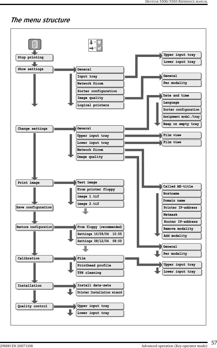
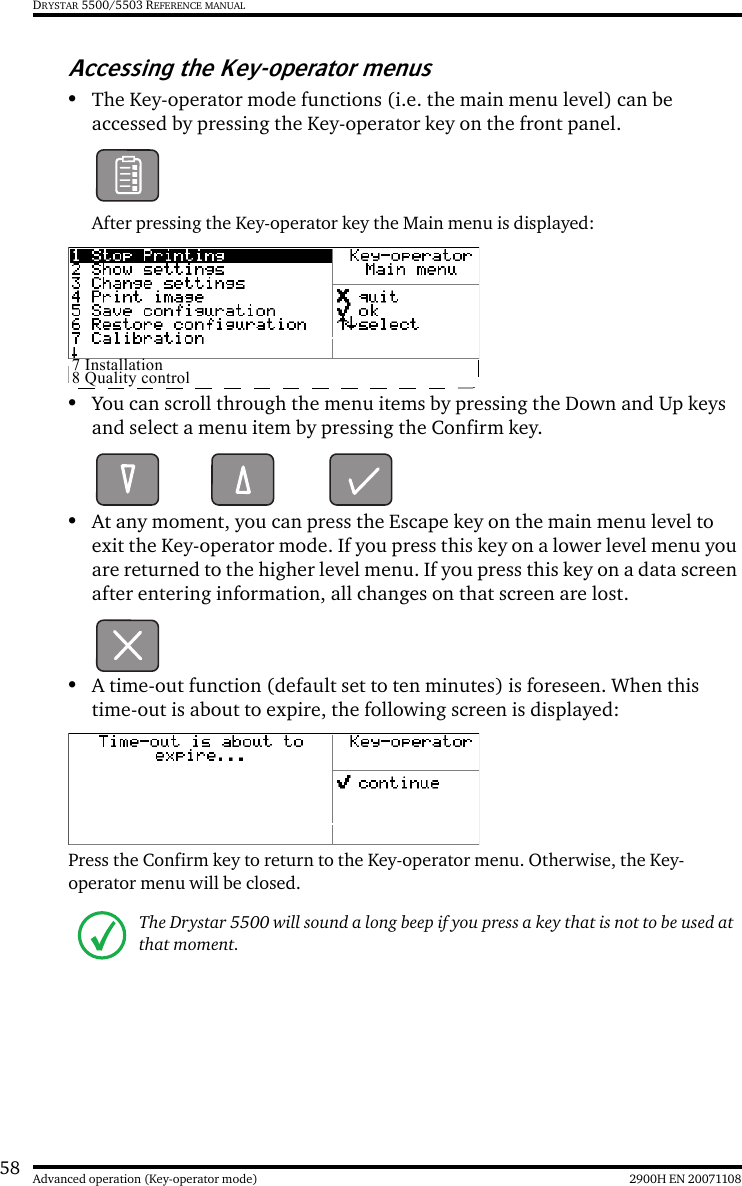
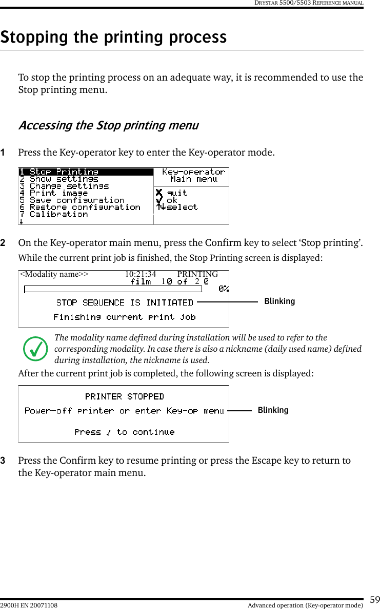
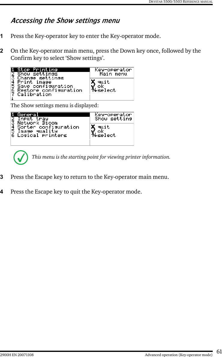
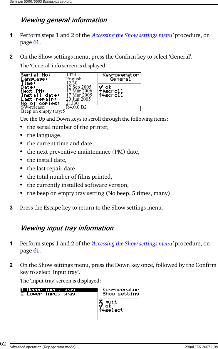
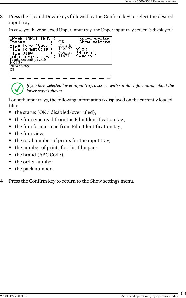
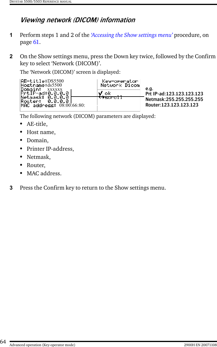
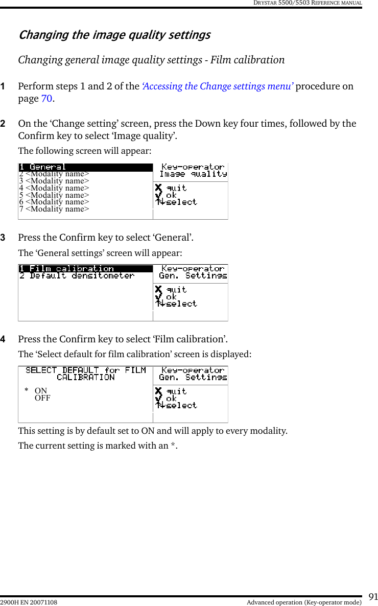
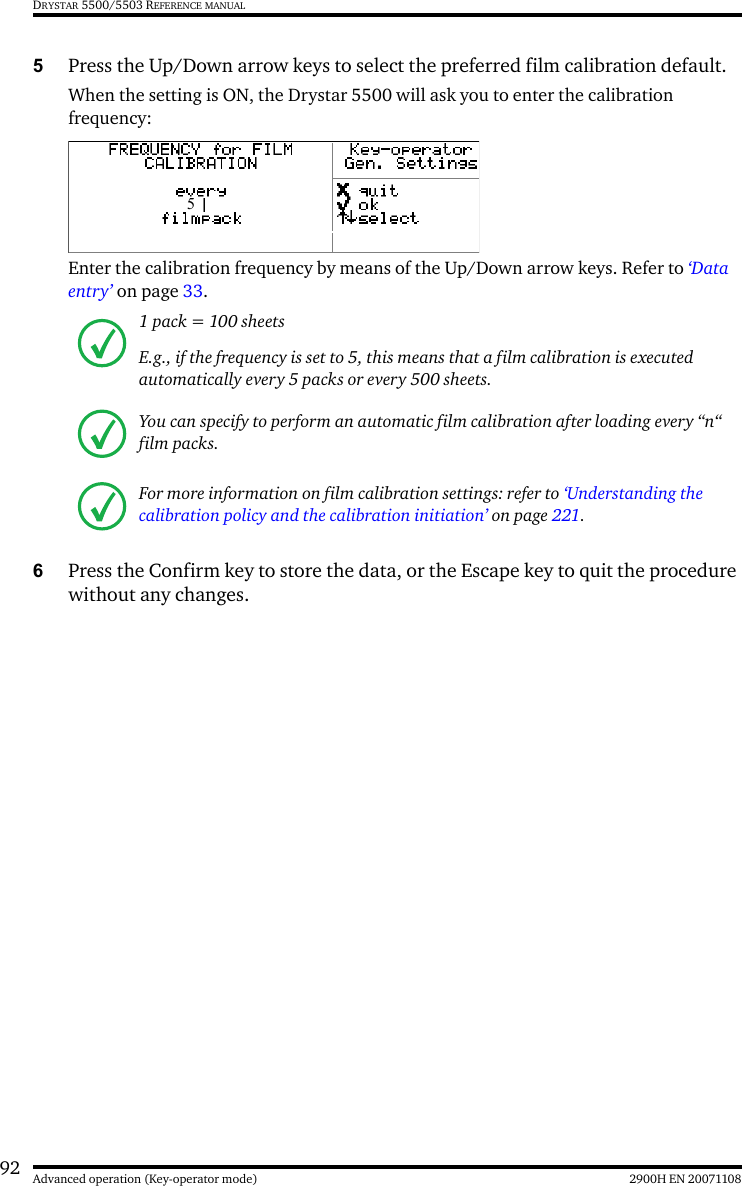
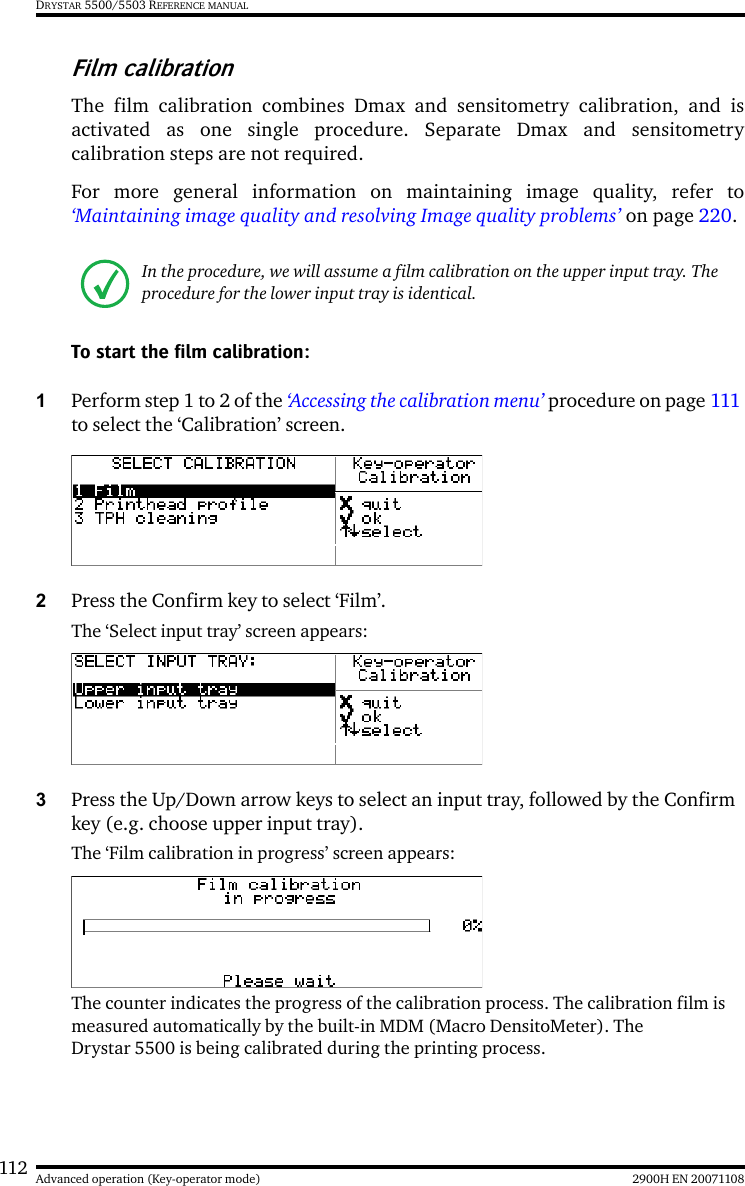
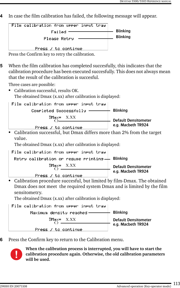
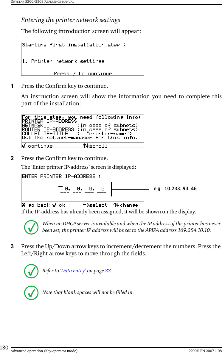
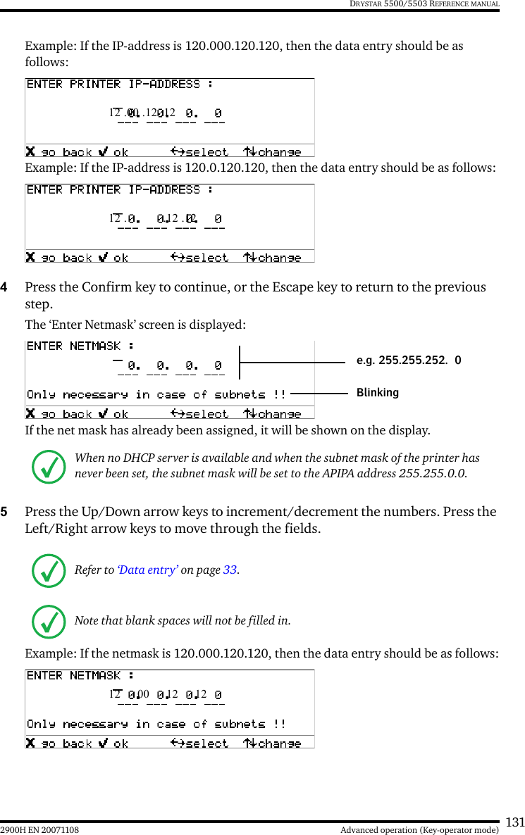
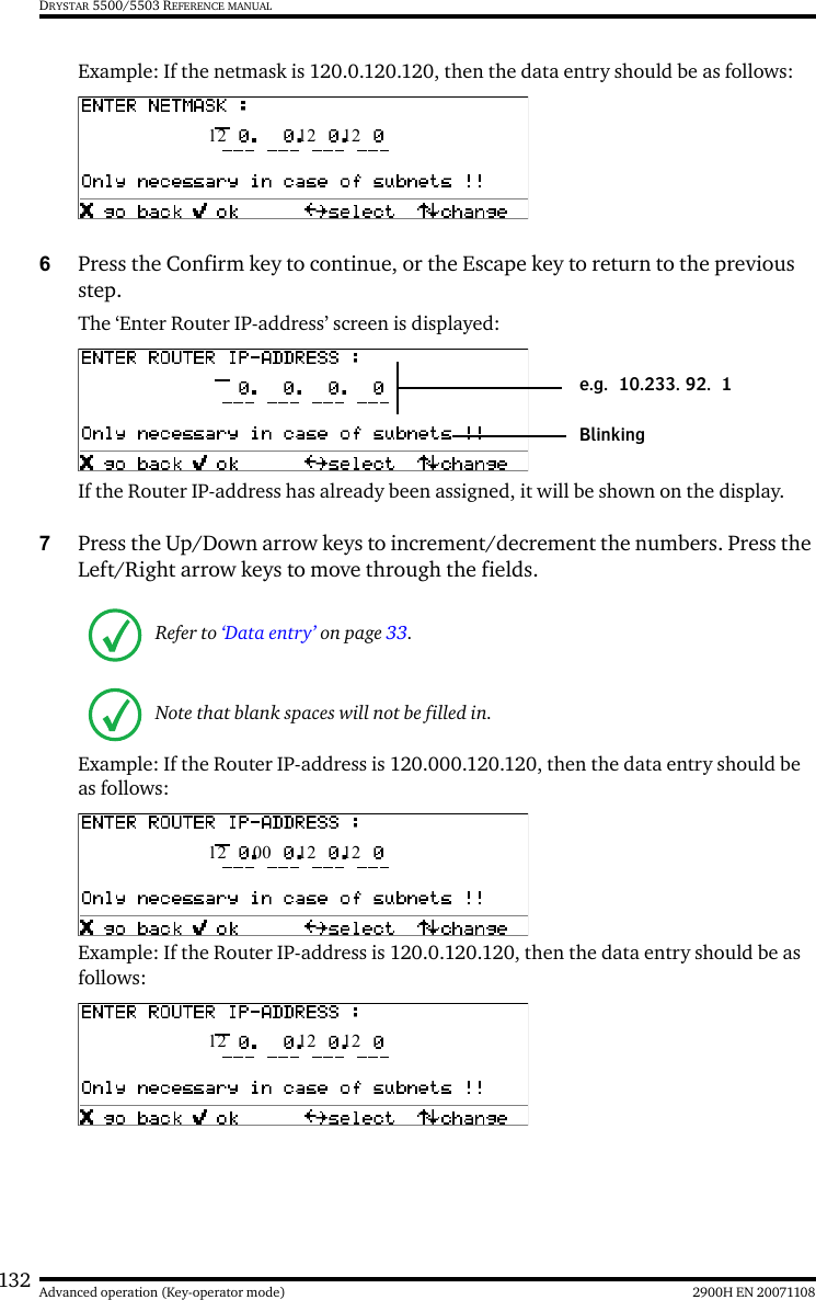
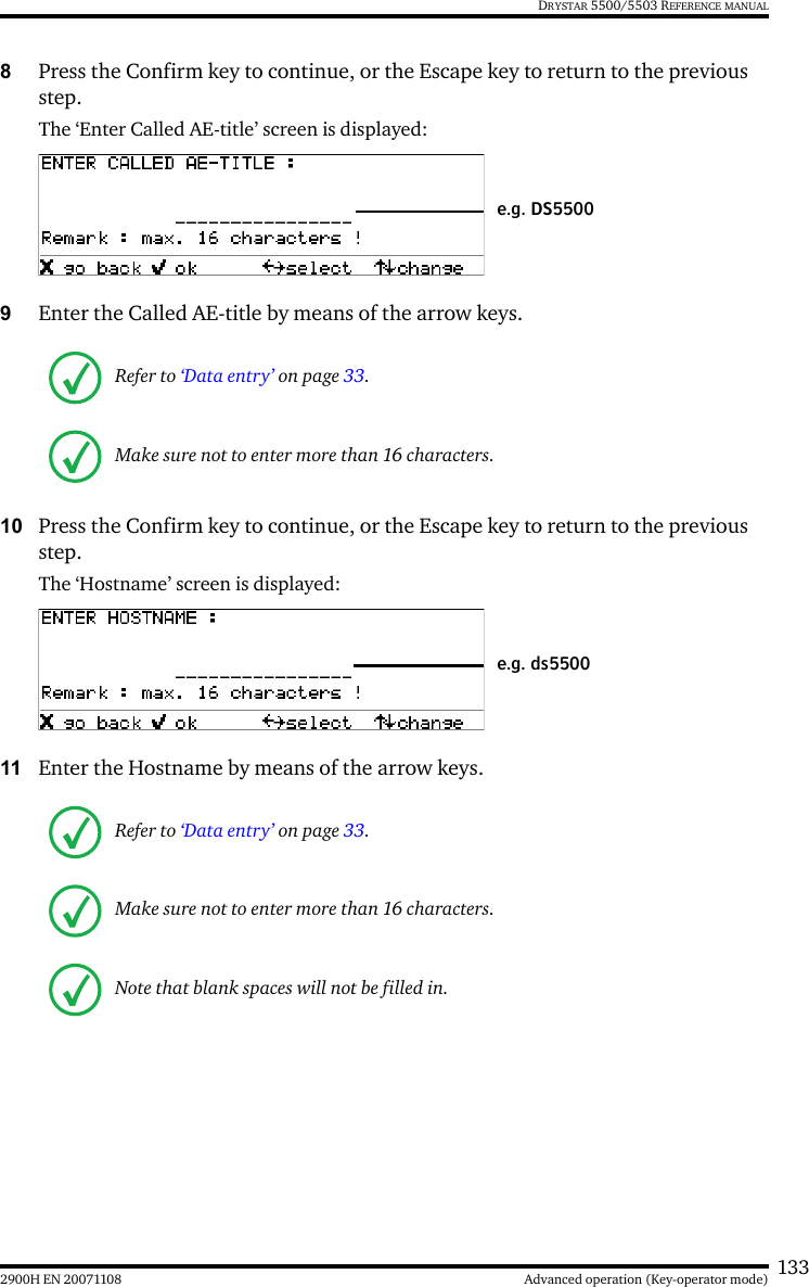
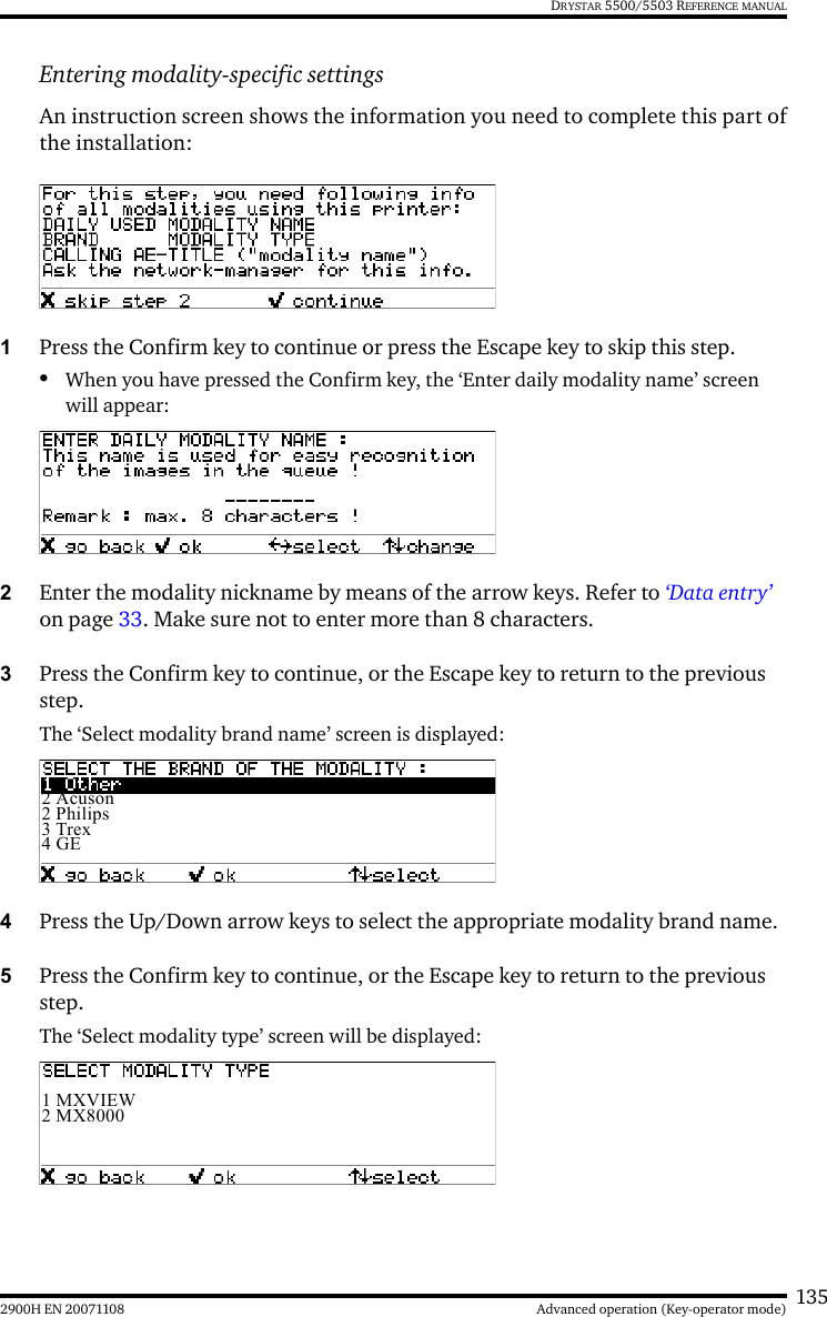
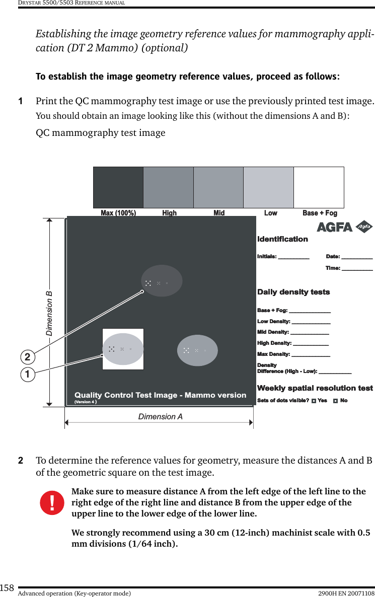
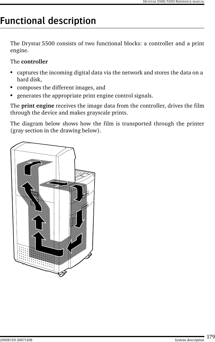
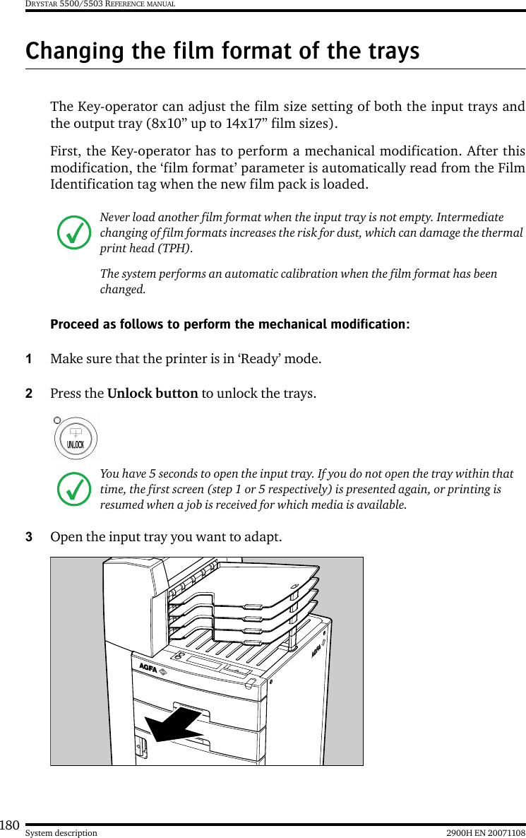
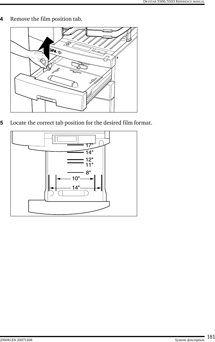
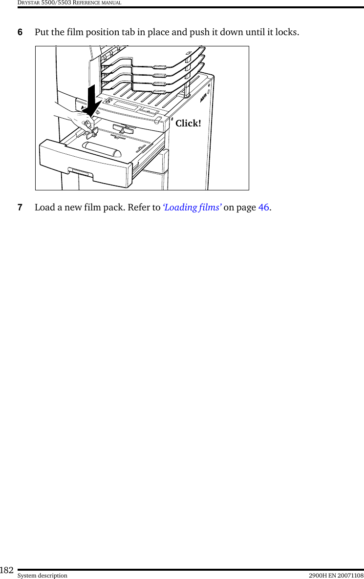
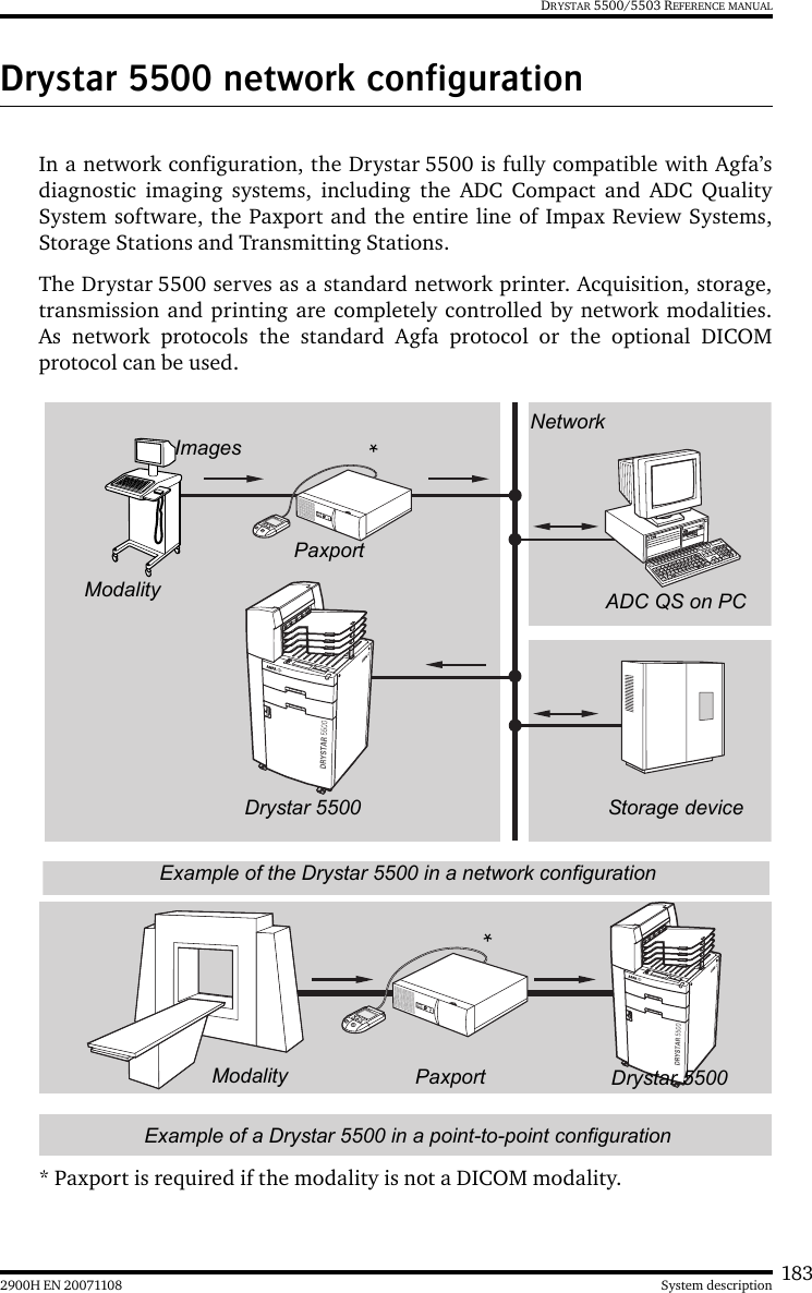
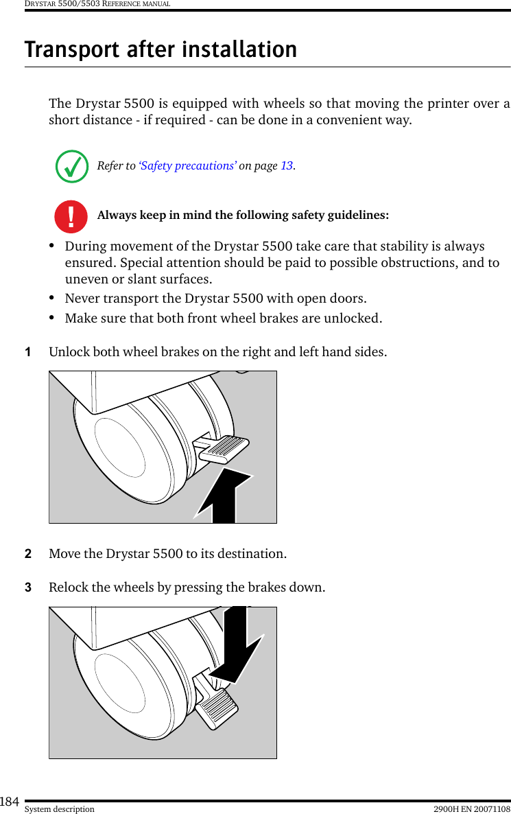
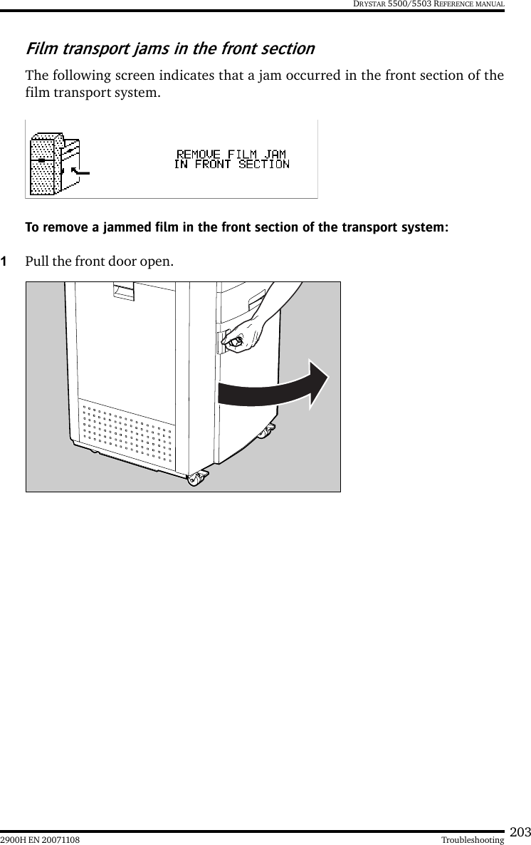
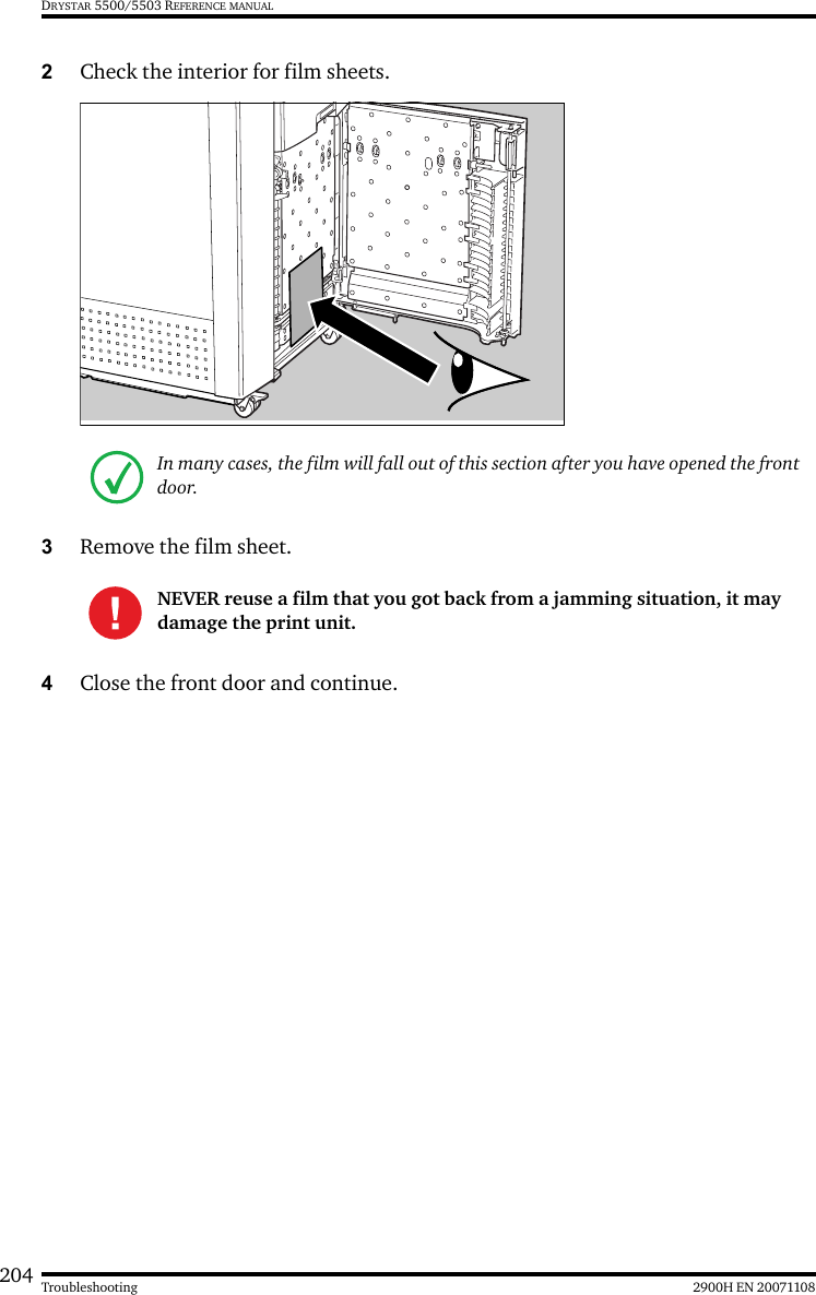
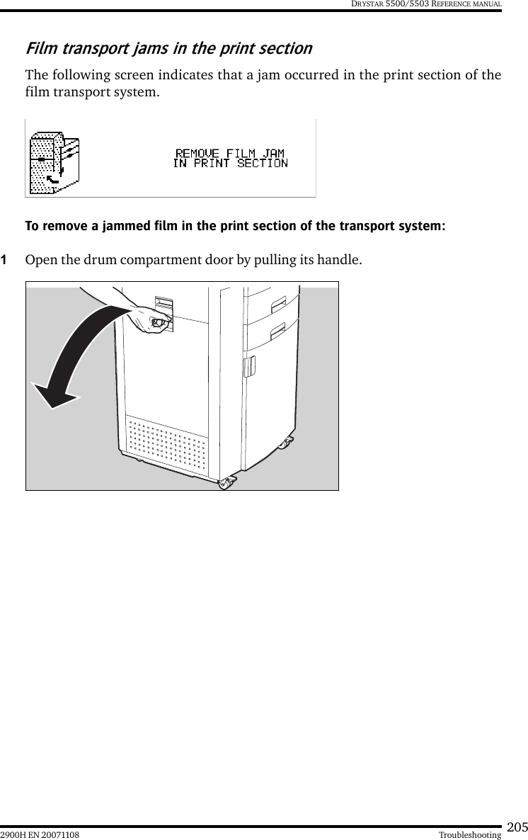
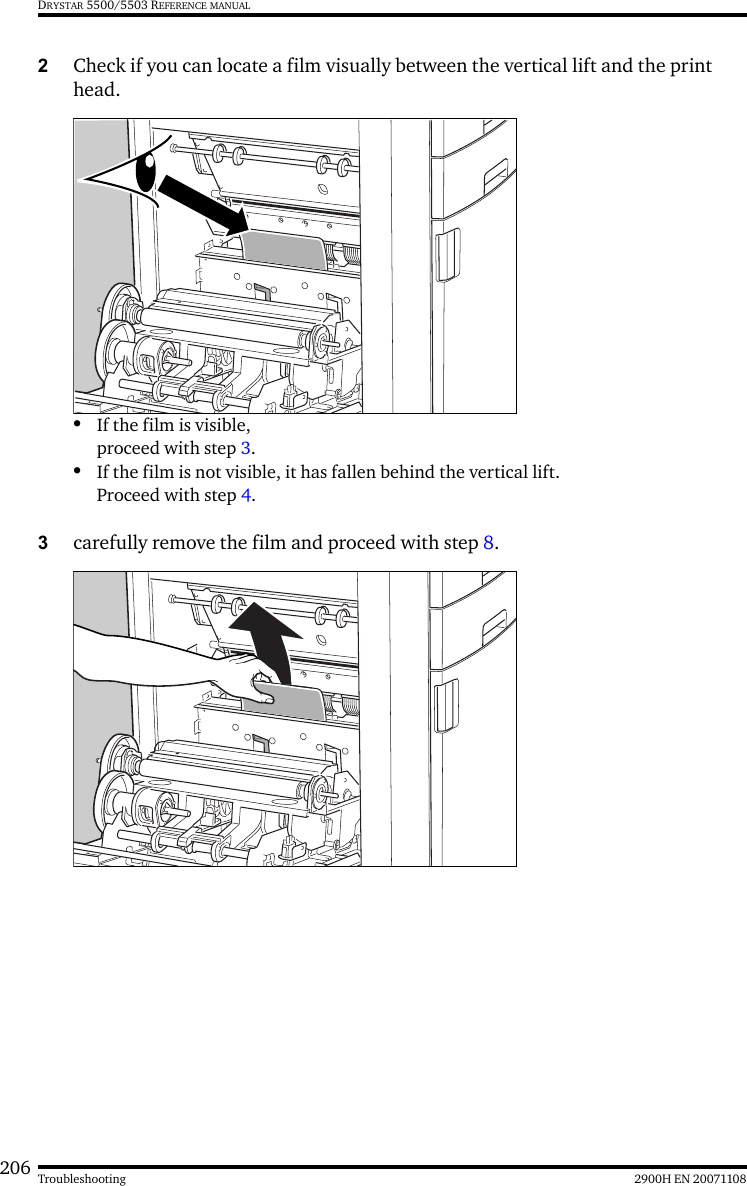
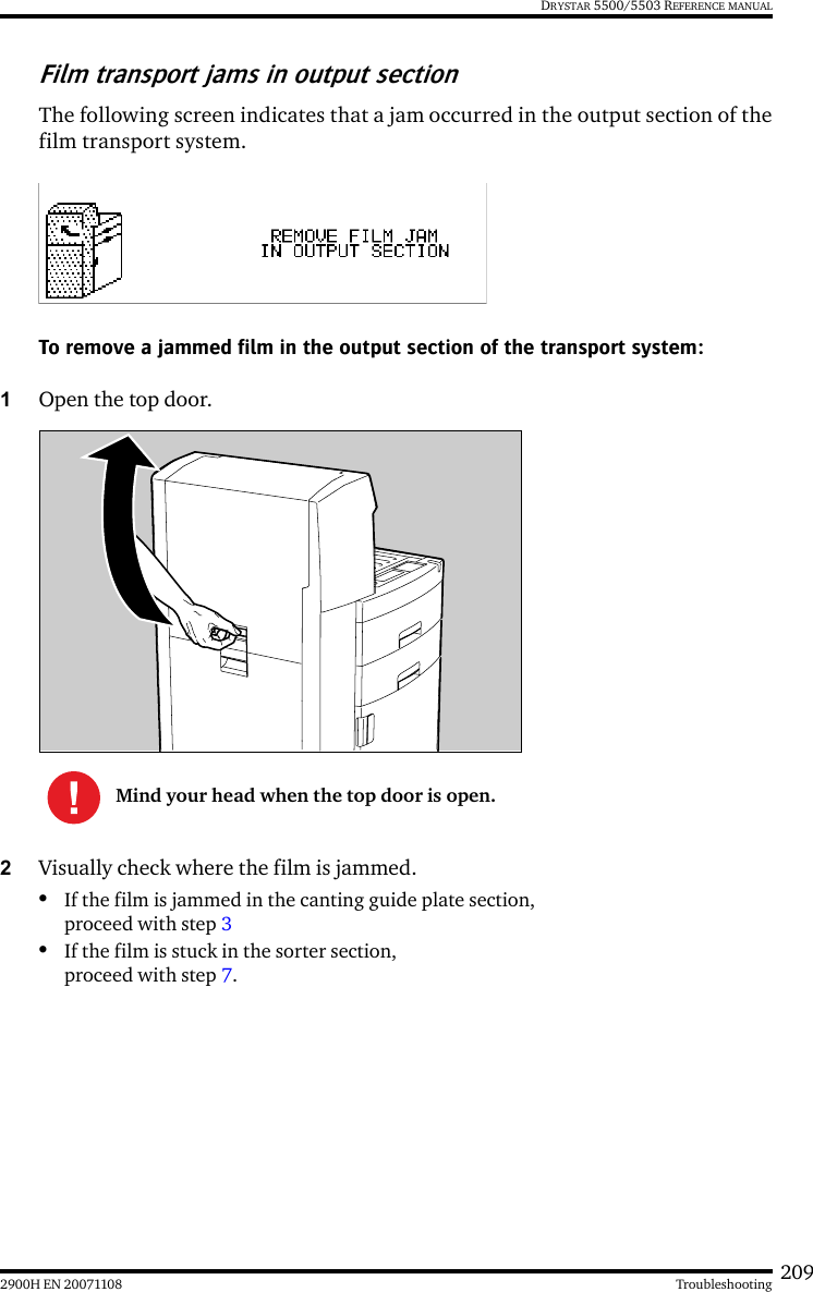
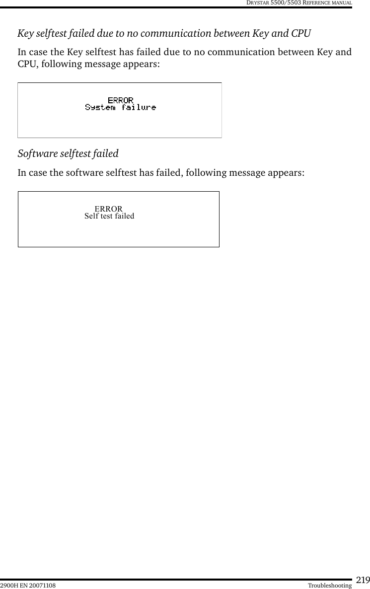
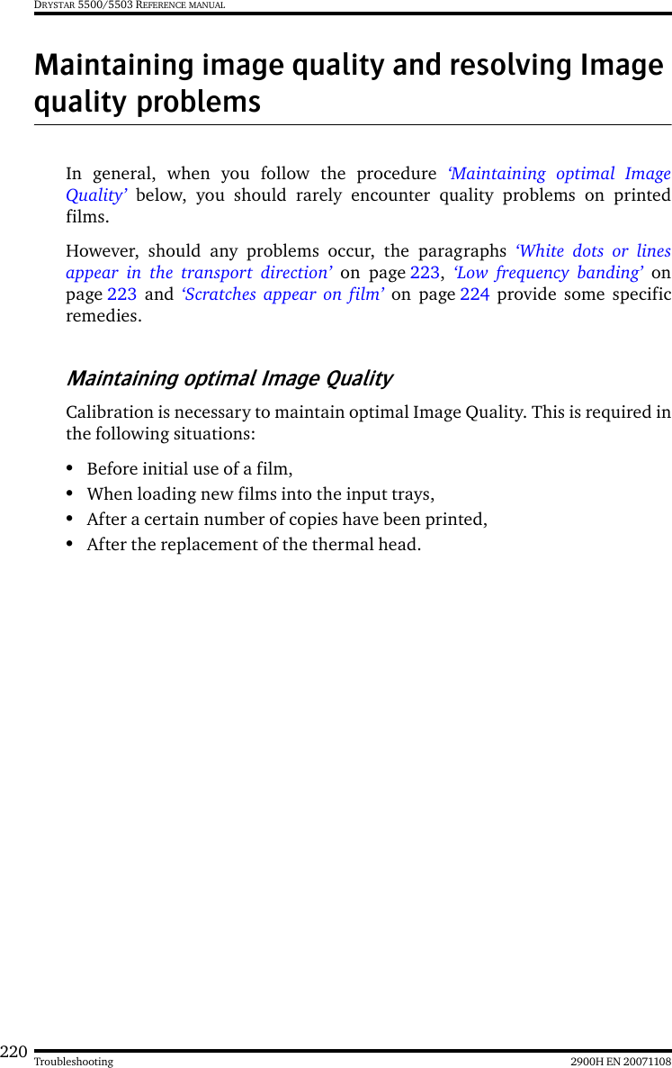
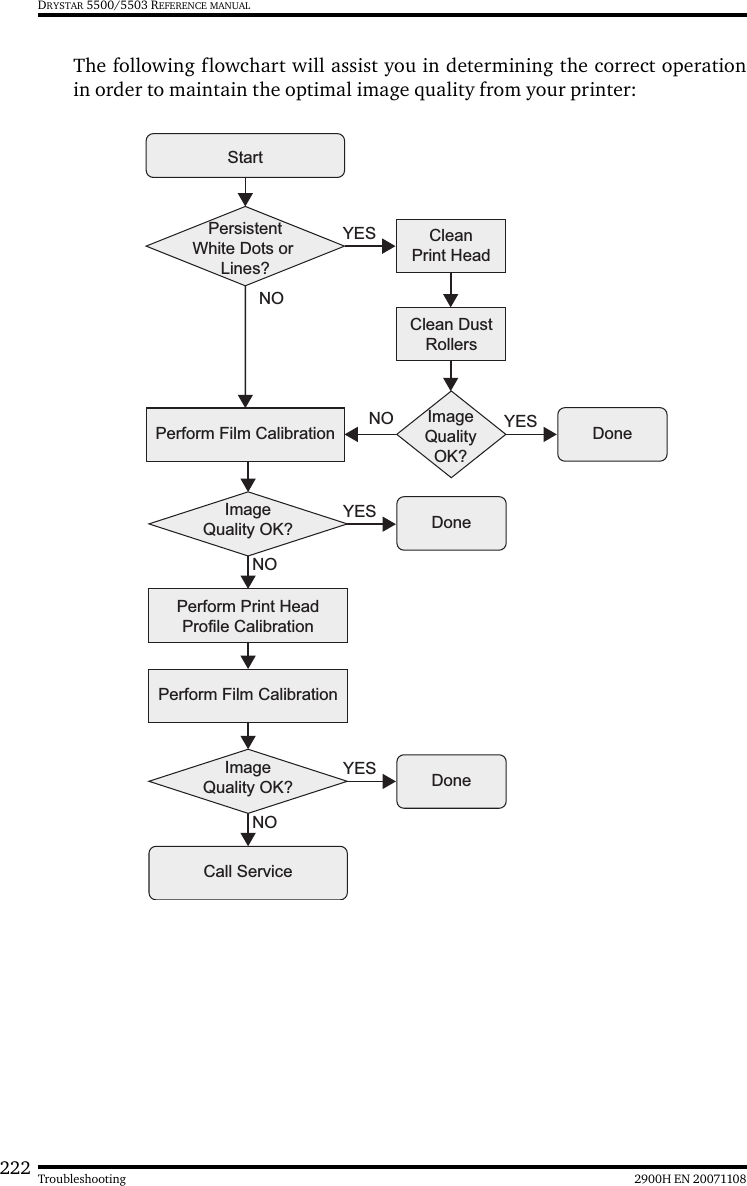
Agfa Gevaert N V 5364A Drystar550X/xxx Medical tabletop printer User Manual Drystar 5500 5503
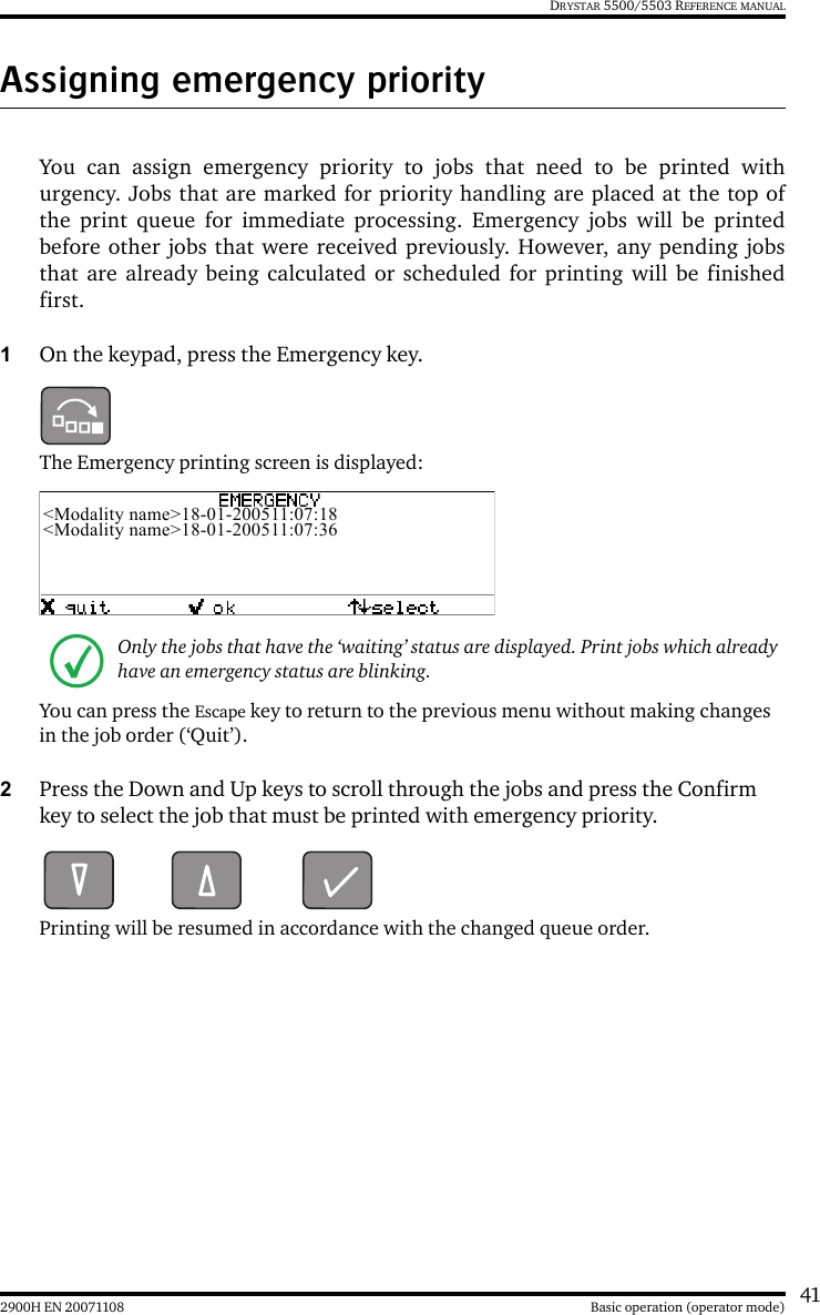
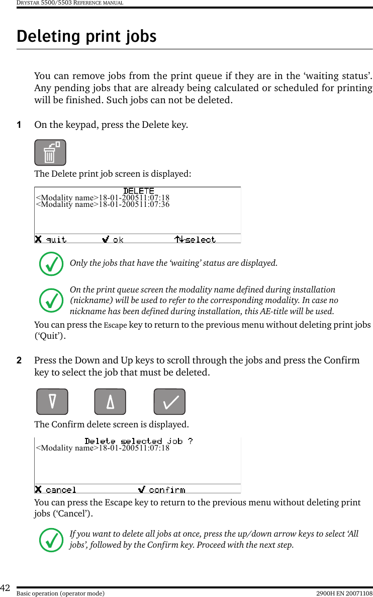
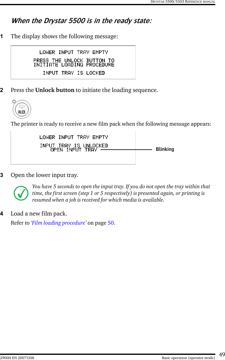
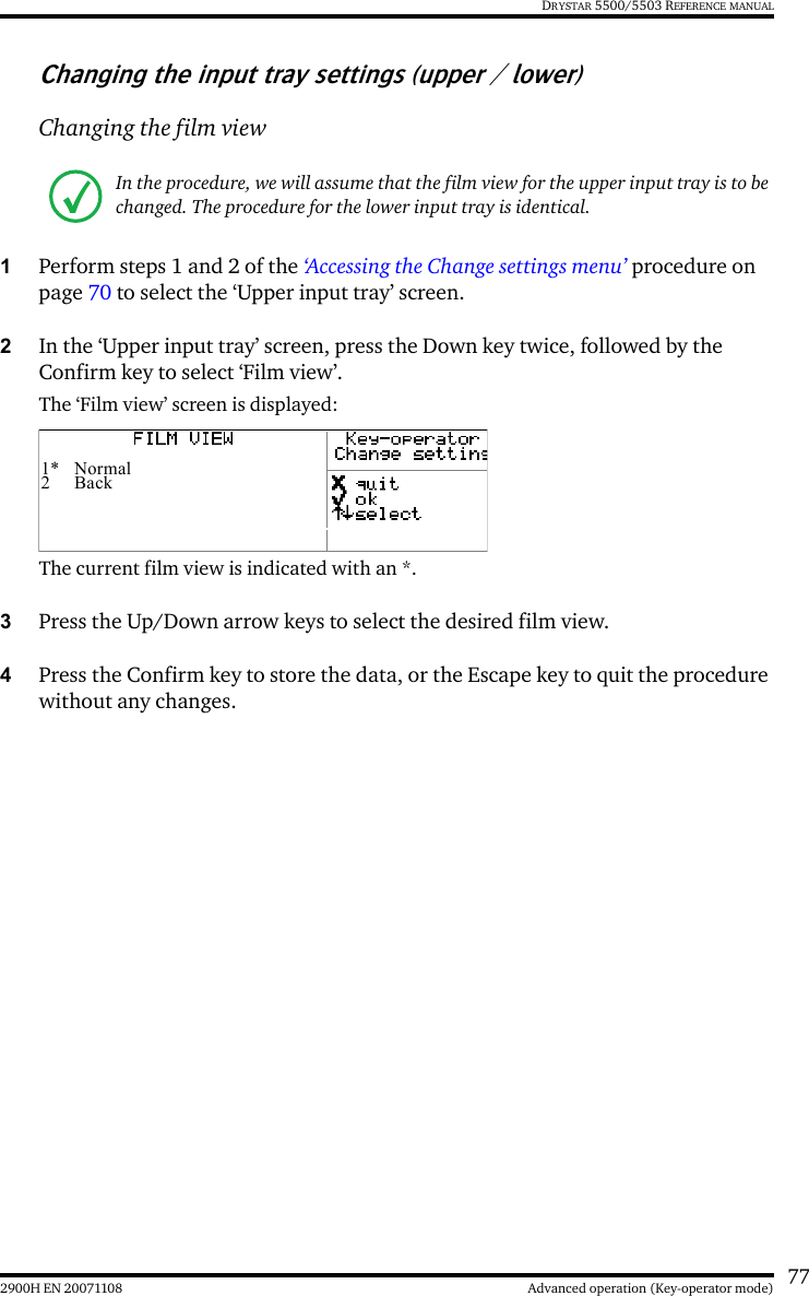
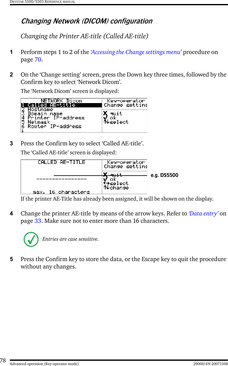
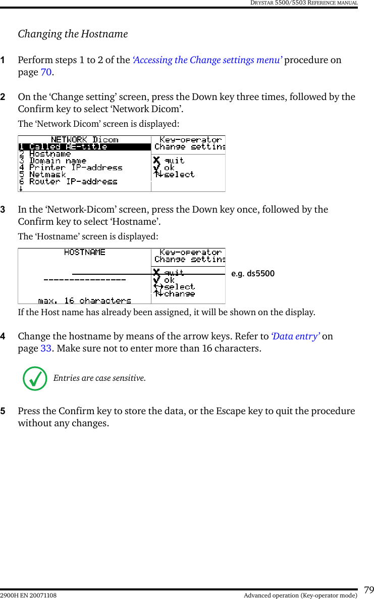
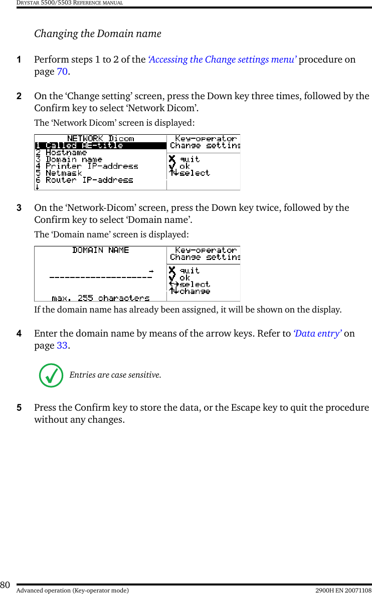
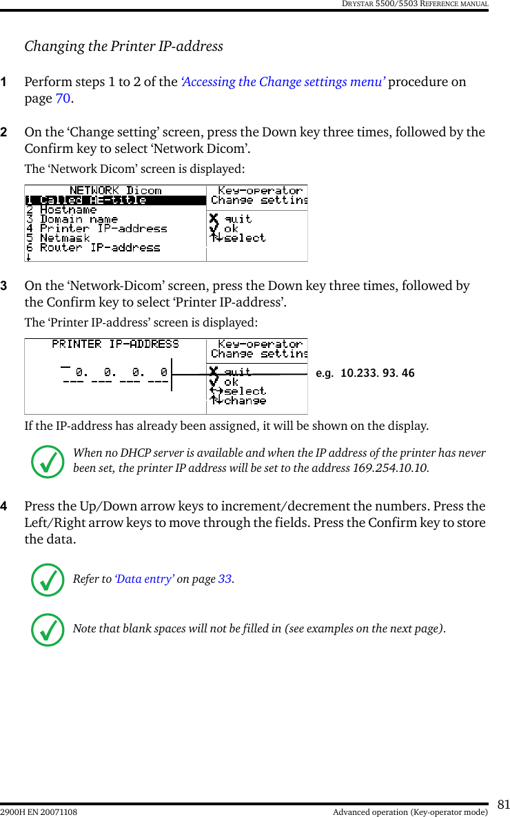
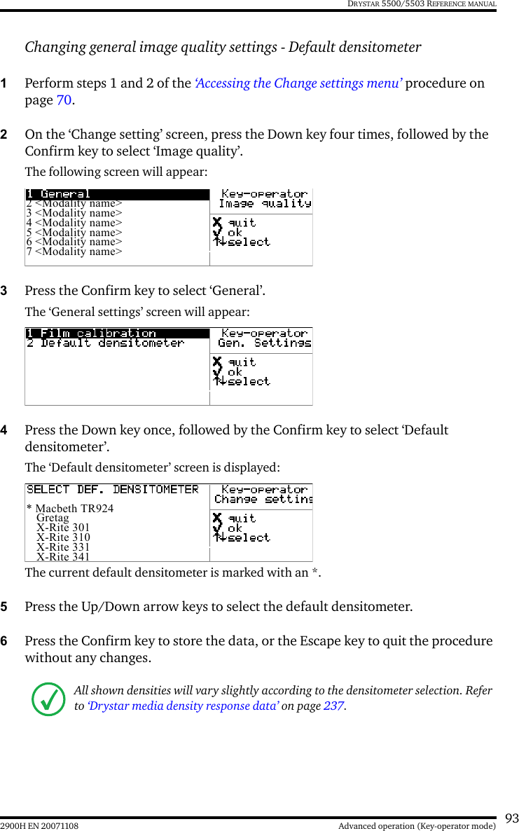
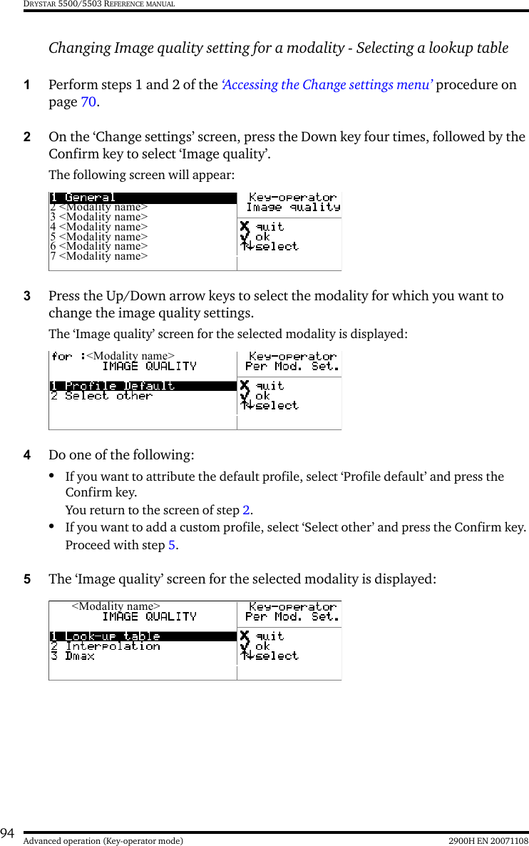
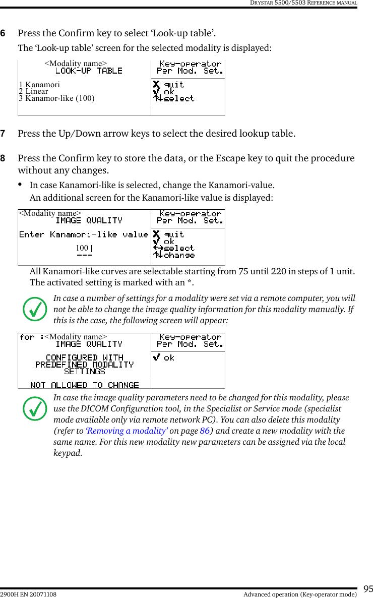
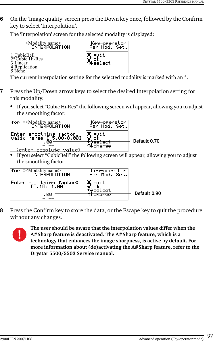
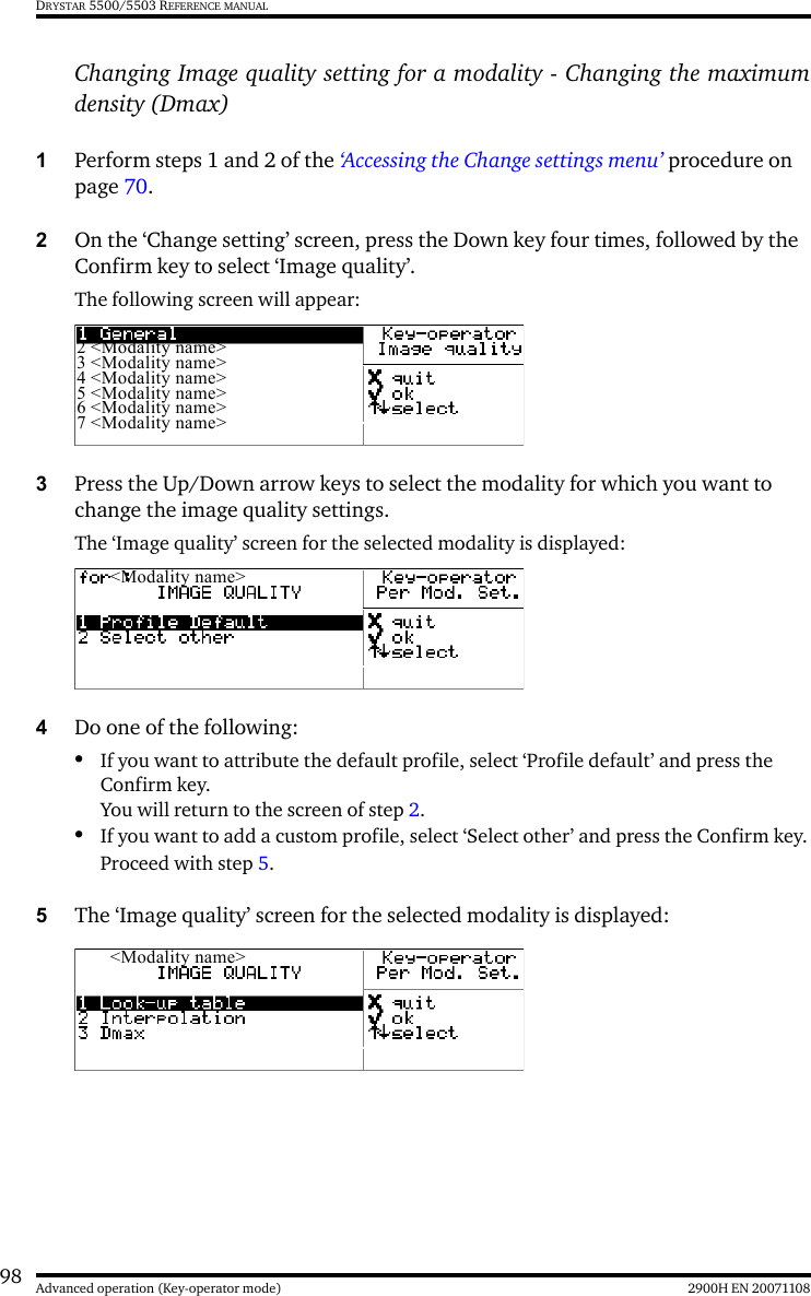
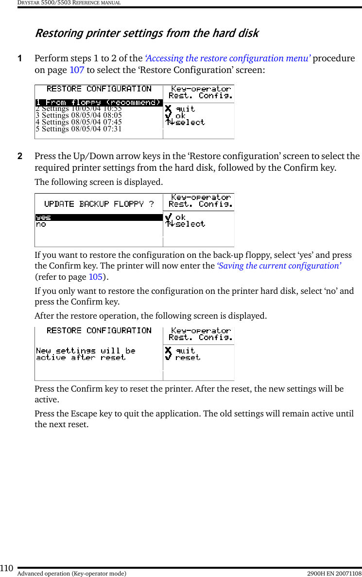
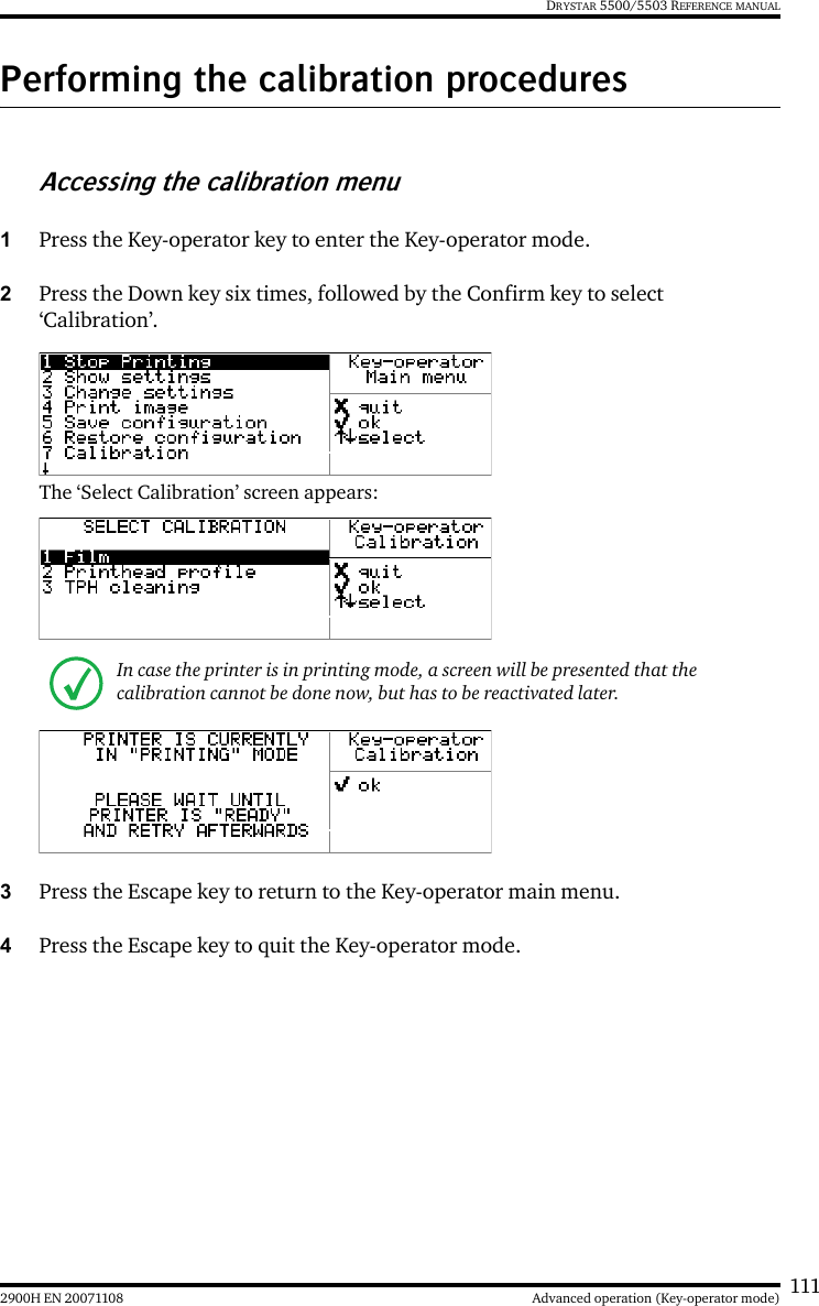
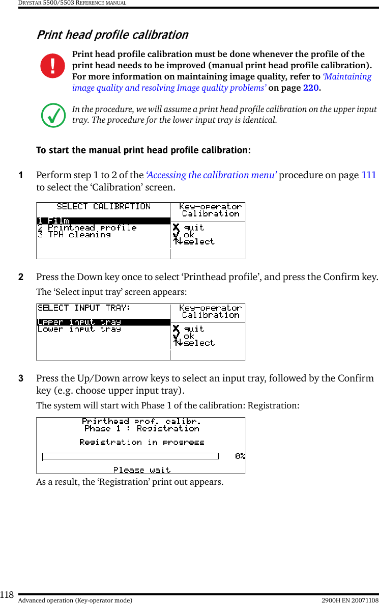
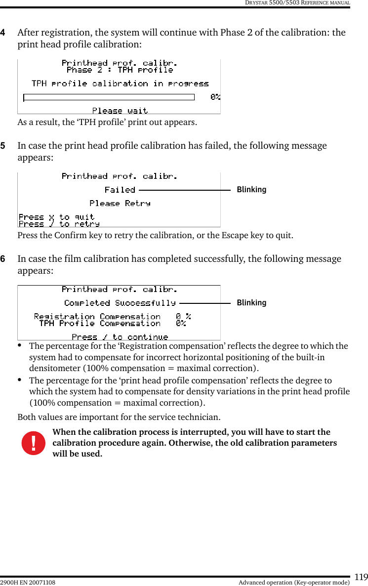
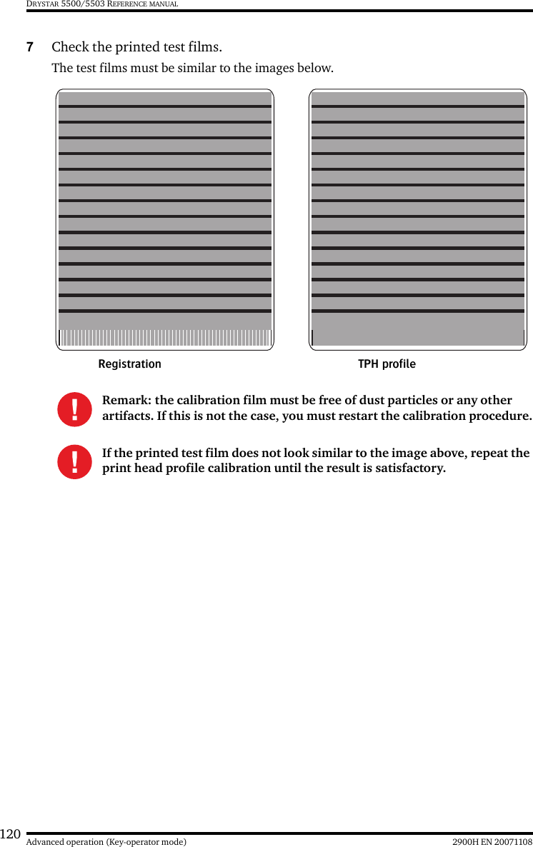
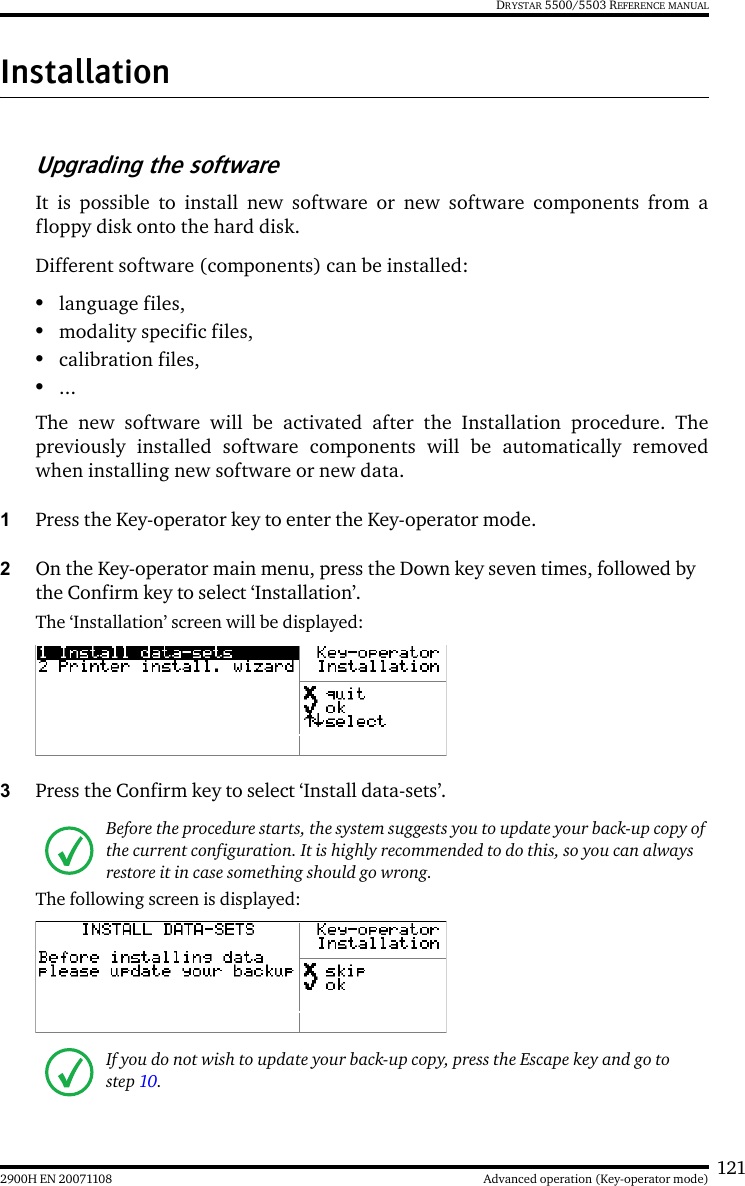
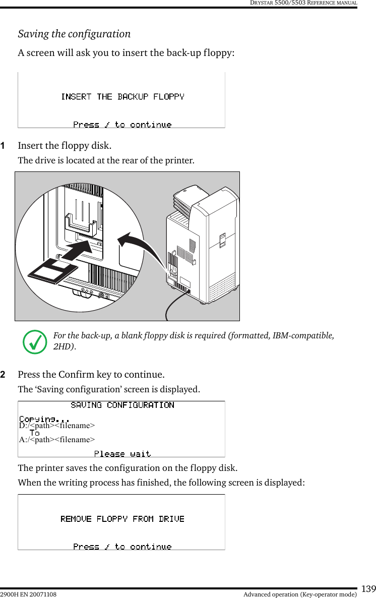
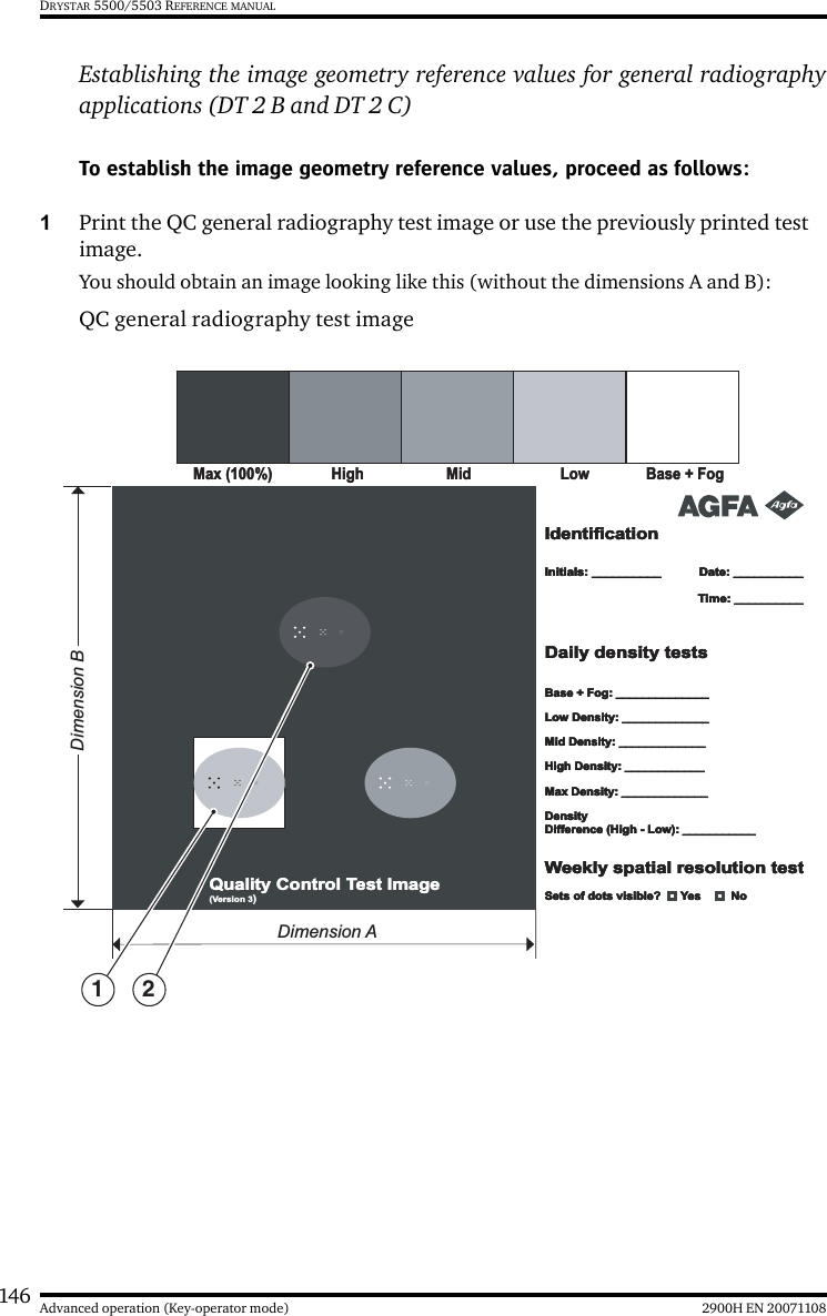
Agfa Gevaert N V Drystar550X/xxx Medical tabletop printer Drystar 5500 5503
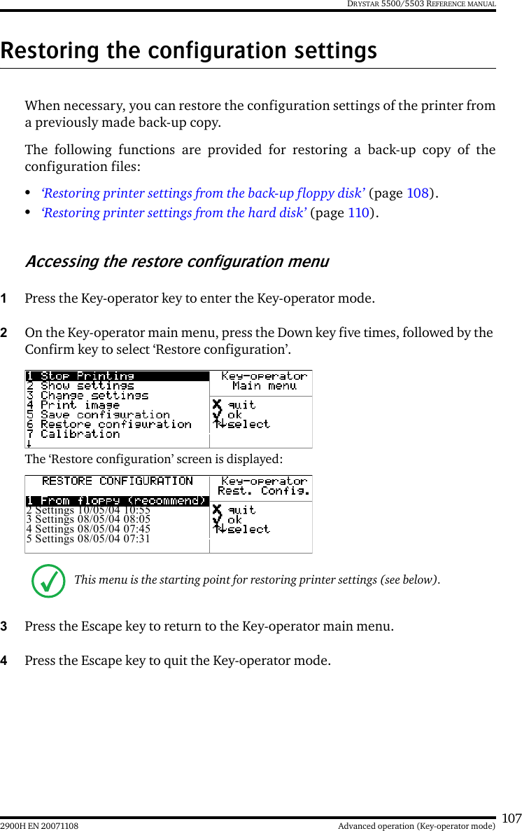
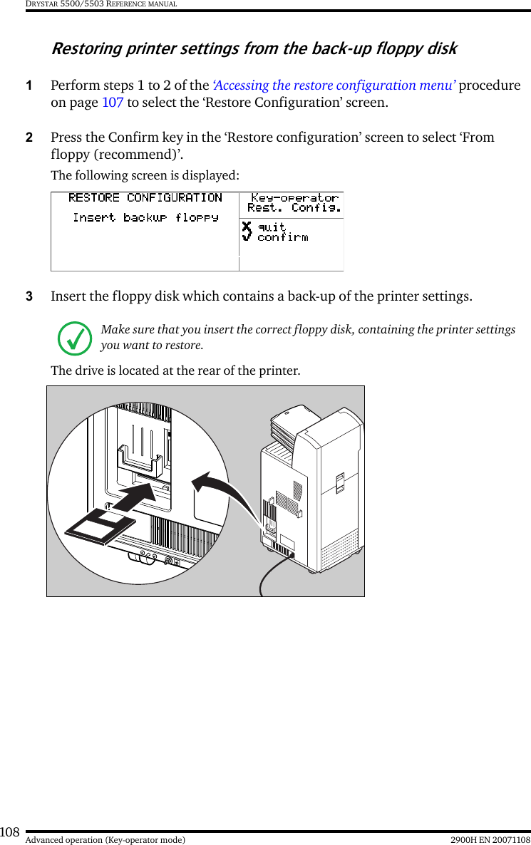
UserManual.wiki
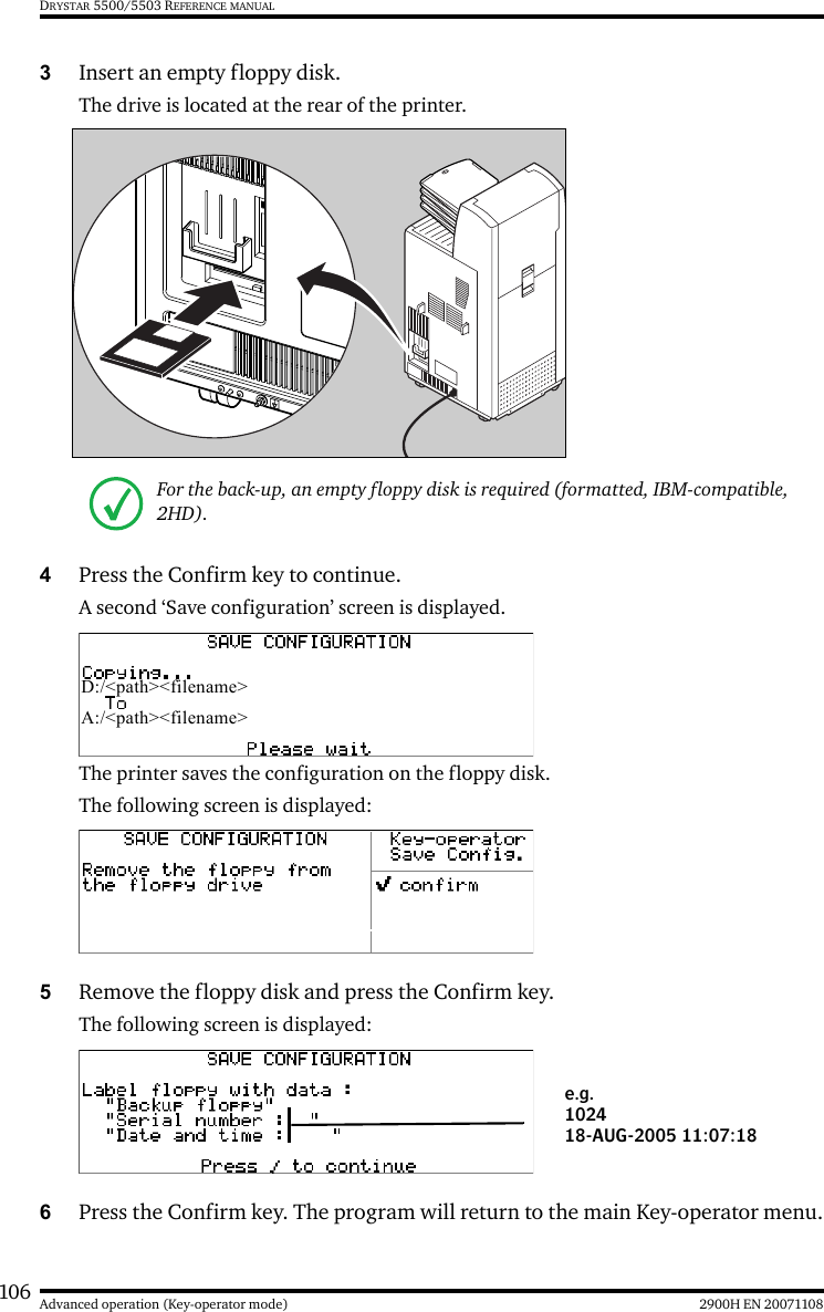
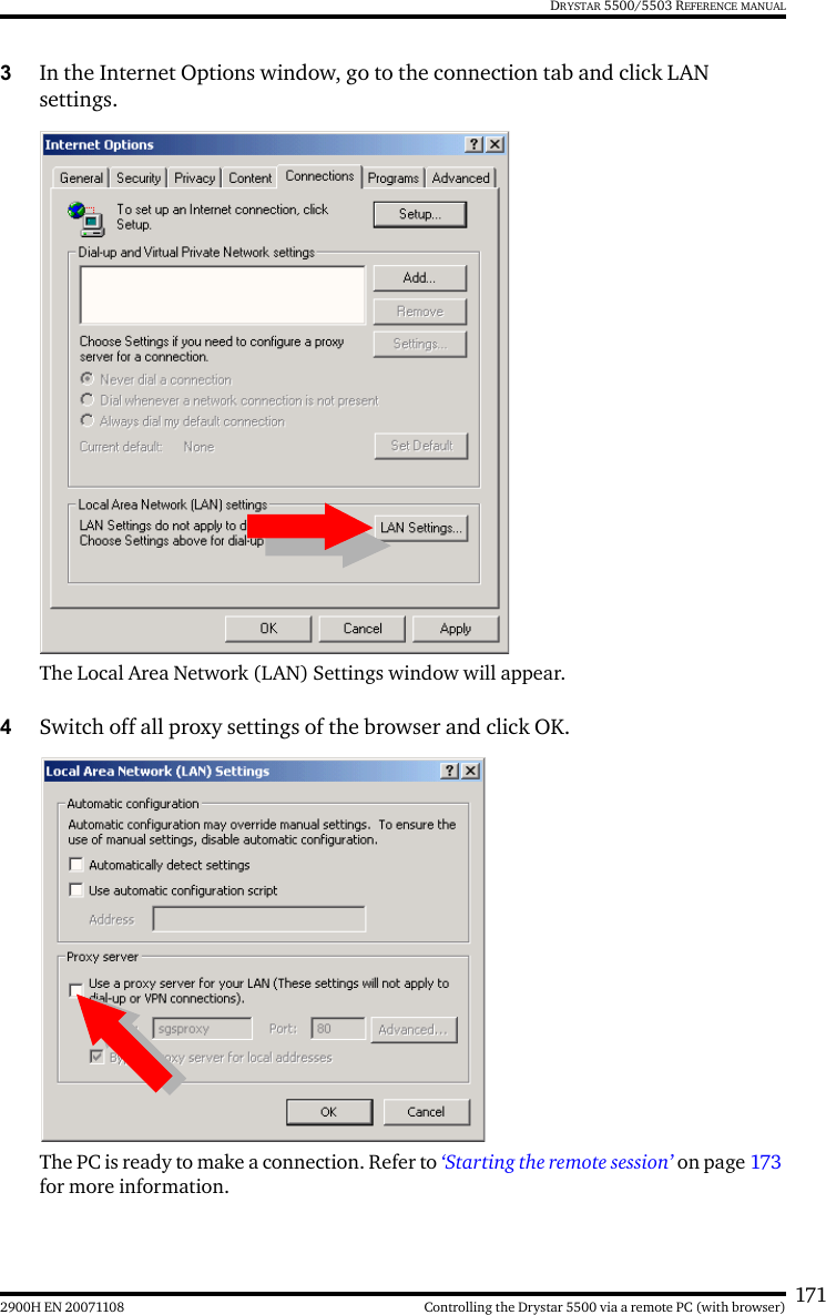
>
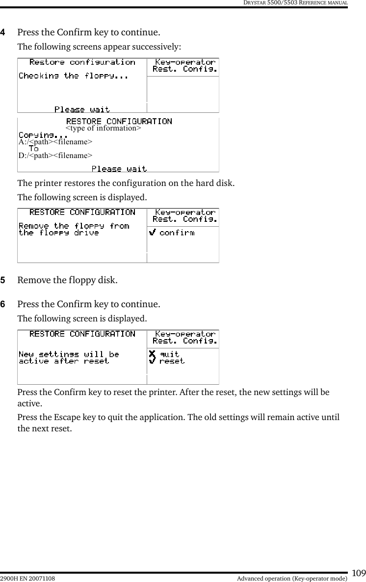
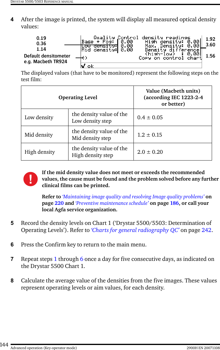
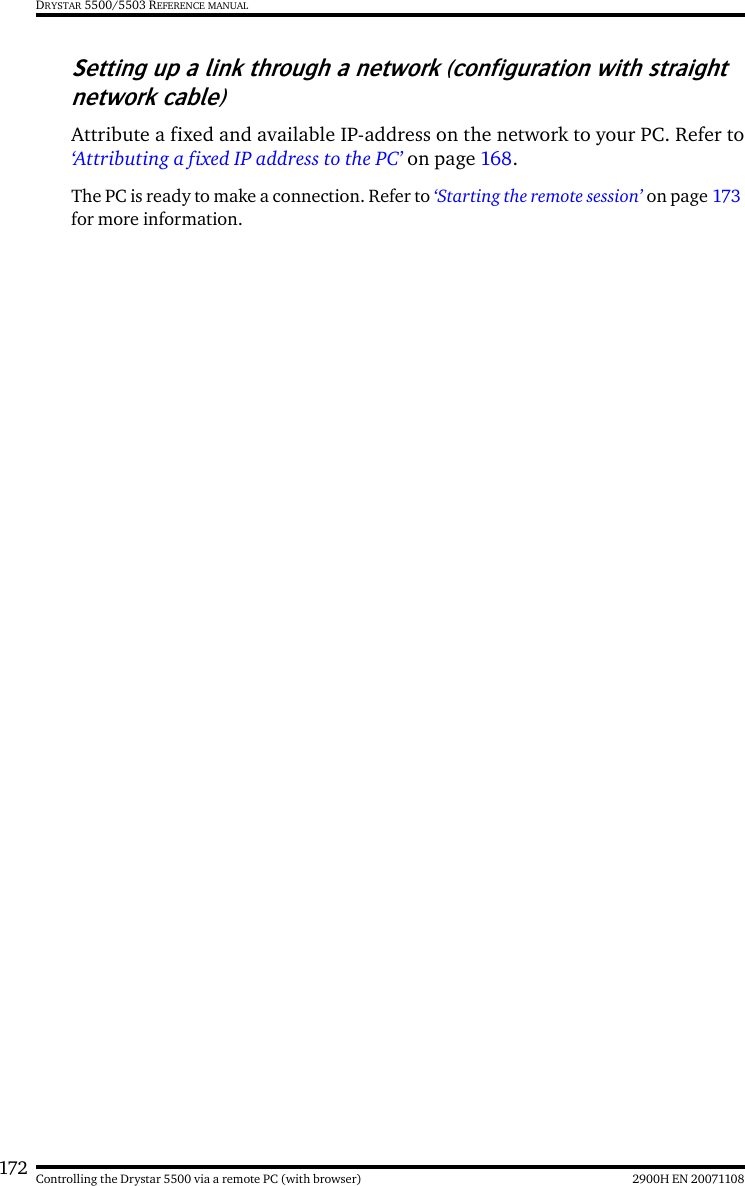
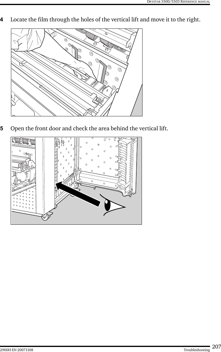
Agfa Gevaert N V
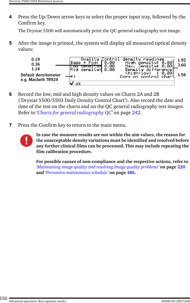
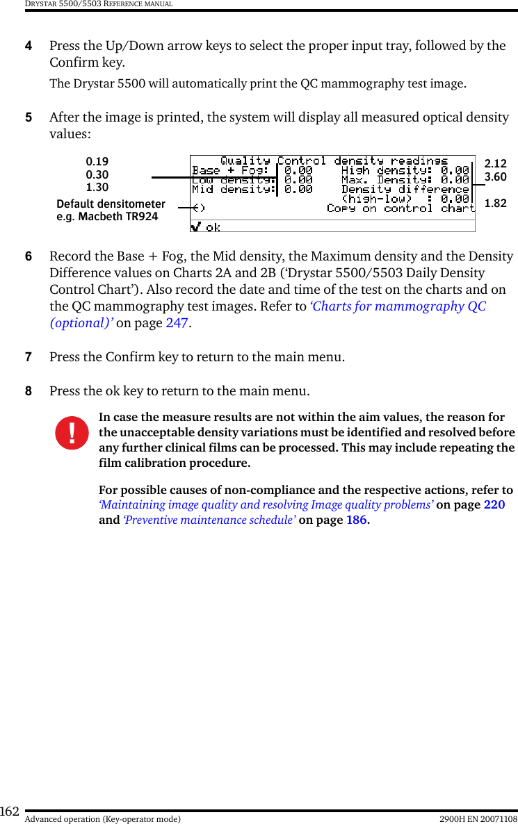
>
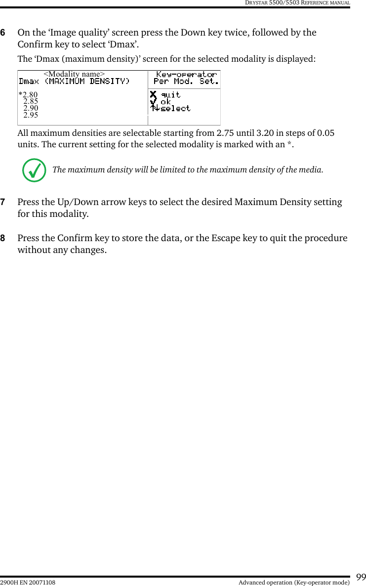
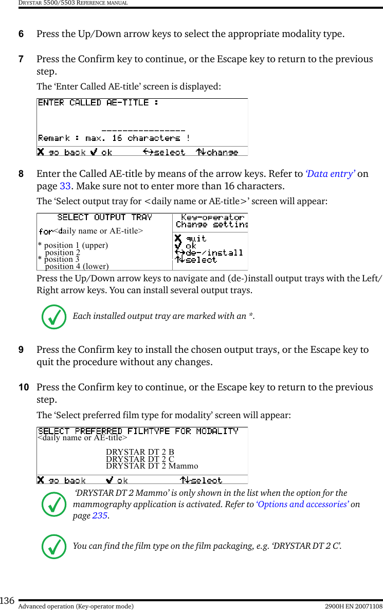
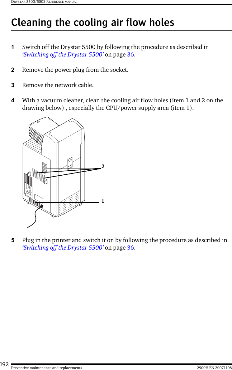
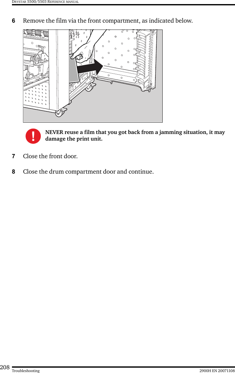
5364A User Manual
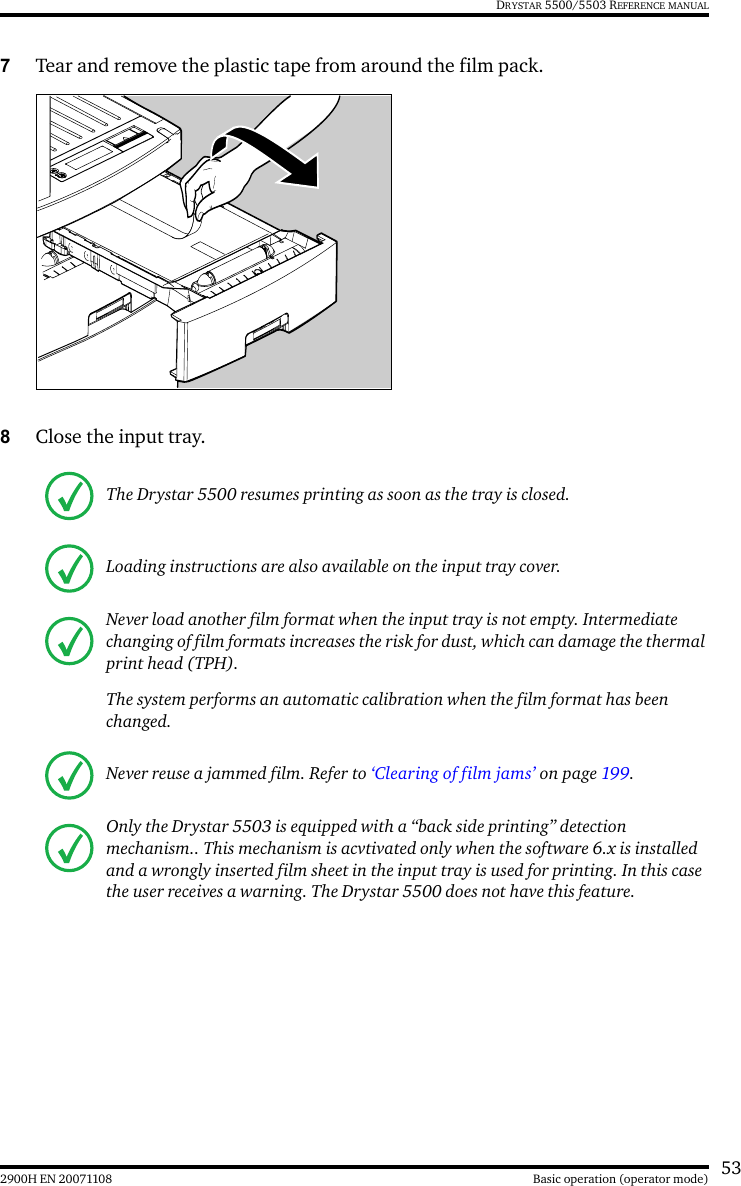
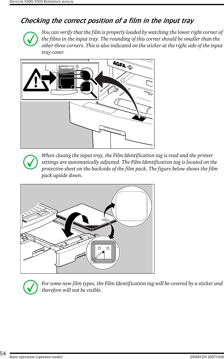
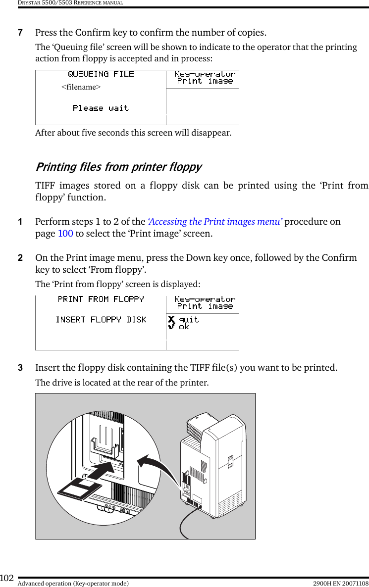
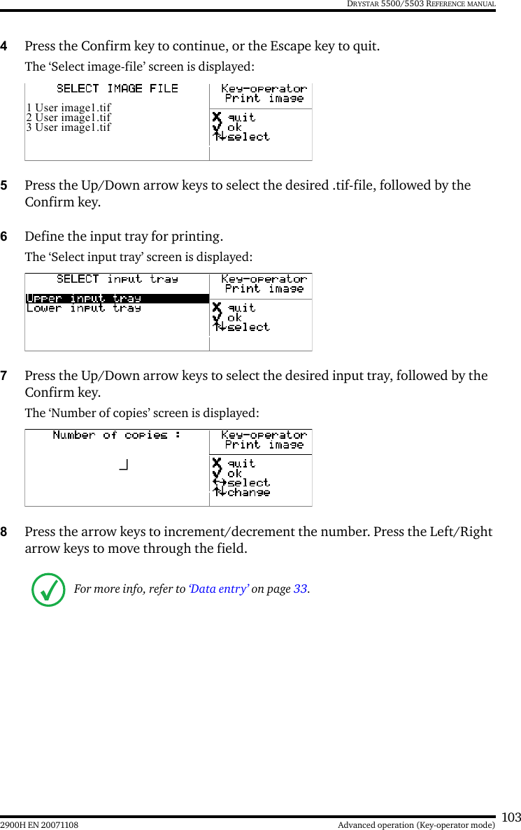
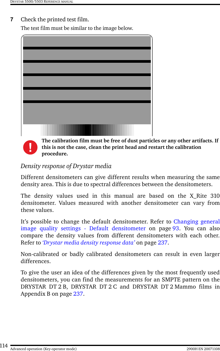
manual
Navigation menu
Upload a User Manual
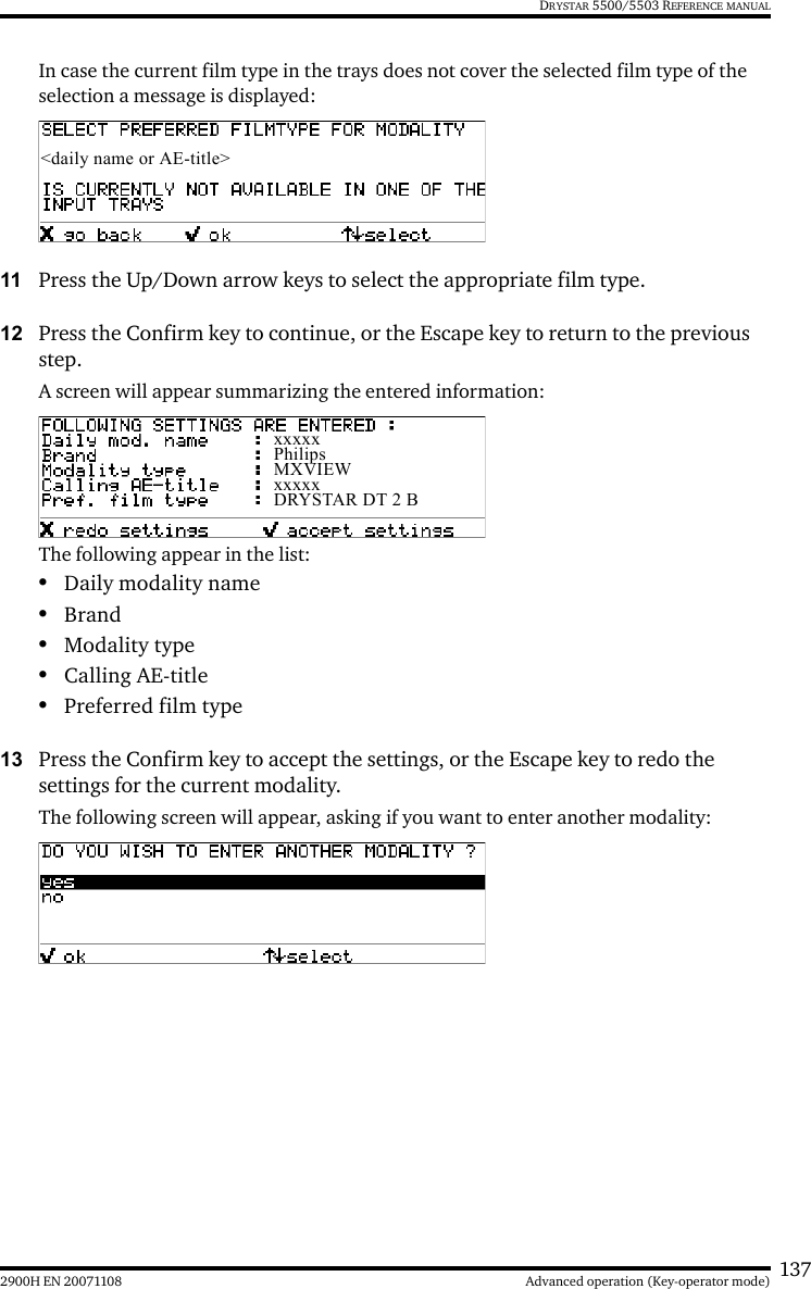
Namespaces
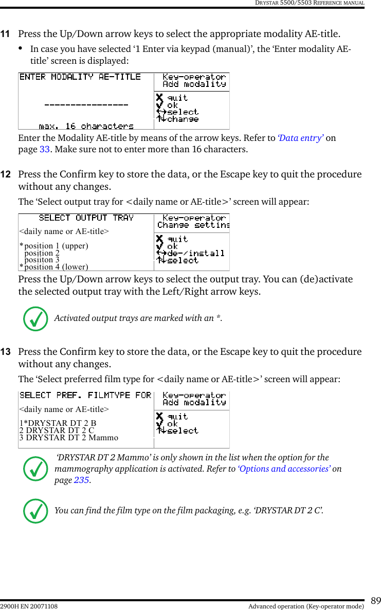
Wiki Guide
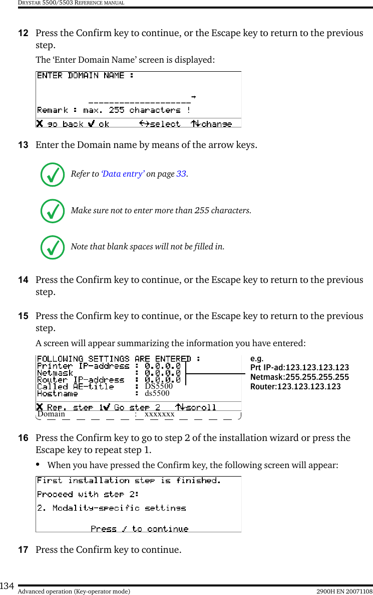
HTML
PDF
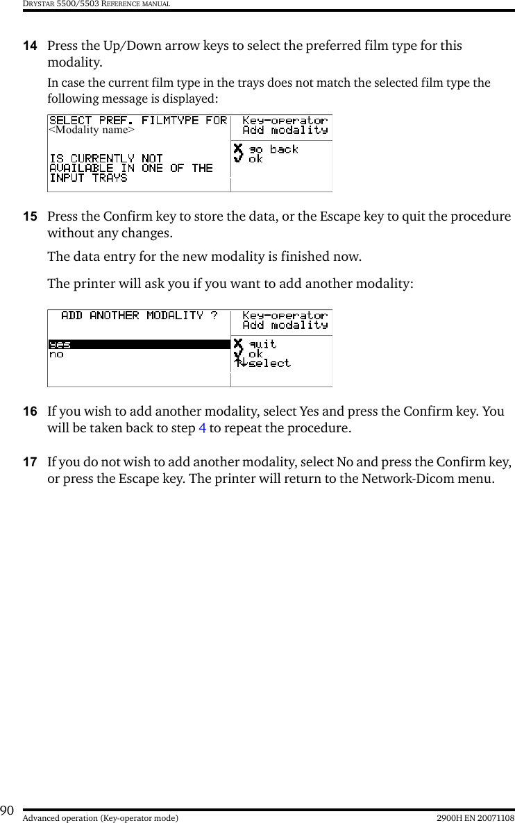
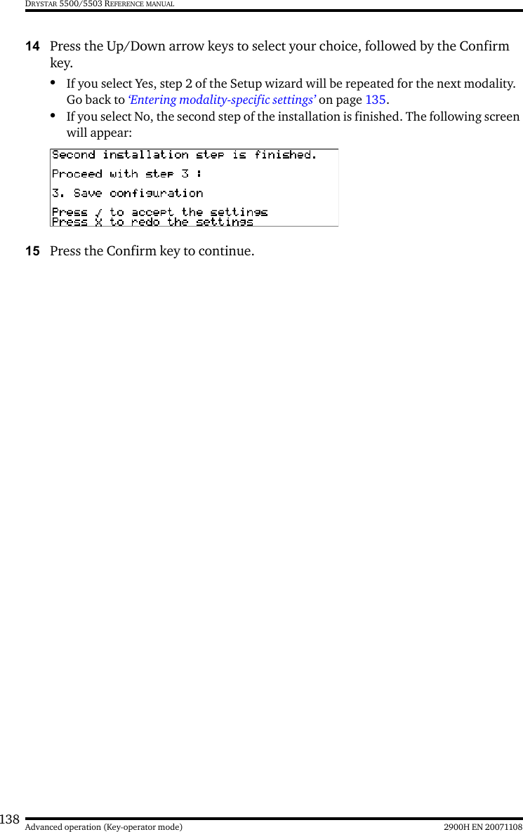
Info
Views
User Manual
Discussion / Help
Navigation