Agfa Gevaert N V 5364A Drystar550X/xxx Medical tabletop printer User Manual Drystar 5500 5503
Agfa Gevaert N V Drystar550X/xxx Medical tabletop printer Drystar 5500 5503
manual
Drystar 5500/5503
Reference manual
2900H EN 20071108
22900H EN 20071108
DRYSTAR 5500/5503 REFERENCE MANUAL
Figure 1: CE-Label
For more information on Agfa products and Agfa HealthCare products, please visit www.agfa.com.
Agfa and the Agfa rhombus are trademarks of Agfa-Gevaert N.V., Belgium or its affiliates. Drystar 5500-5503
is a trademark of Agfa HealthCare N.V., Belgium or one of its affiliates. All other trademarks are held by their
respective owners and are used in an editorial fashion with no intention of infringement.
Agfa HealthCareN.V. makes no warranties or representation, expressed or implied, with respect to the accu-
racy, completeness or usefulness of the information contained in this document and specifically disclaims war-
ranties of suitability for any particular purpose. Products and services may not be available for your local area.
Please contact your local sales representative for availability information. Agfa HealthCare N.V. diligently
strives to provide as accurate information as possible, but shall not be responsible for any typographical error.
Agfa HealthCare N.V. shall under no circumstances be liable for any damage arising from the use or inability to
use any information, apparatus, method or process disclosed in this document. Agfa HealthCare N.V. reserves
the right to make changes to this document without prior notice.
Copyright 2007 Agfa HealthCare N.V.
All rights reserved.
Published by Agfa HealthCare N.V.
B-2640 Mortsel - Belgium.
No part of this document may be reproduced, copied, adapted or transmitted in any form or by any means
without the written permission of Agfa HealthCare N.V.
0413

3
2900H EN 20071108
DRYSTAR 5500/5503 REFERENCE MANUAL
Table of contents
About this manual ..........................................................................................7
Chapter 1: Introducing the Drystar 5500 ..................................................9
Drystar 5500 features...................................................................................10
Safety precautions ........................................................................................13
Security precautions.....................................................................................17
Safety compliance.........................................................................................18
Privacy and security .....................................................................................22
Operating modes ..........................................................................................24
Control modes (local and remote) ...............................................................26
The local user interface ................................................................................27
Switching on the Drystar 5500.....................................................................34
Cooling down the Drystar 5500 ...................................................................36
Switching off the Drystar 5500 ....................................................................36
Chapter 2: Basic operation (operator mode)...........................................37
Overview of operator functions ...................................................................38
Managing the print queue ............................................................................39
Assigning emergency priority ......................................................................41
Deleting print jobs ........................................................................................42
About Drystar 5500 consumables ................................................................44
Loading films ................................................................................................46
Chapter 3: Advanced operation (Key-operator mode)..........................55
Overview of Key-operator functions ............................................................56
Stopping the printing process ......................................................................59
Viewing printer information ........................................................................60
Changing the configuration settings ............................................................69
Printing images...........................................................................................100
Saving the configuration settings...............................................................105
Restoring the configuration settings..........................................................107
Performing the calibration procedures...................................................... 111
Installation .................................................................................................121
Quality control for general radiography applications (DT 2 B & DT 2 C)
.......... 141
Quality control for mammography application (DT 2 Mammo) (optional)
....153

42900H EN 20071108
DRYSTAR 5500/5503 REFERENCE MANUAL
Chapter 4: Controlling the Drystar 5500 via a remote PC (with
browser)......................................................................................................... 165
Features ......................................................................................................166
Setup........................................................................................................... 167
Setting up the connection .......................................................................... 168
Starting the remote session........................................................................ 173
Chapter 5: System description.................................................................. 177
Main components ....................................................................................... 178
Functional description ............................................................................... 179
Changing the film format of the trays........................................................180
Drystar 5500 network configuration .........................................................183
Transport after installation ........................................................................184
Chapter 6: Preventive maintenance and replacements.......................185
Preventive maintenance schedule..............................................................186
Cleaning the exterior.................................................................................. 187
Cleaning the dust rollers ............................................................................188
Cleaning the cooling air flow holes............................................................192
Chapter 7: Troubleshooting....................................................................... 193
Troubleshooting checklist .......................................................................... 194
The Drystar 5500 does not print ................................................................ 196
Clearing of film jams .................................................................................. 199
Film identification problems ...................................................................... 214
Start-up errors............................................................................................ 218
Maintaining image quality and resolving Image quality problems ...........220
Warning messages......................................................................................225
Appendix A: Equipment information sheet............................................227
Specifications .............................................................................................228
Viewing the System info area on a film......................................................233
Options and accessories .............................................................................235
Connectivity................................................................................................236

5
2900H EN 20071108
DRYSTAR 5500/5503 REFERENCE MANUAL
Appendix B: Drystar media density response data ...............................237
DRYSTAR DT 2 B .........................................................................................238
DRYSTAR DT 2 C .........................................................................................239
DRYSTAR DT 2 Mammo (optional) ............................................................240
Appendix C: Quality Control Charts ........................................................ 241
Charts for general radiography QC ............................................................242
Charts for mammography QC (optional) ...................................................247
Appendix D: Remarks for HF-emission and immunity.........................253
Appendix E: Index........................................................................................259

62900H EN 20071108
DRYSTAR 5500/5503 REFERENCE MANUAL
7
2900H EN 20071108
DRYSTAR 5500/5503 REFERENCE MANUAL
About this manual
Scope
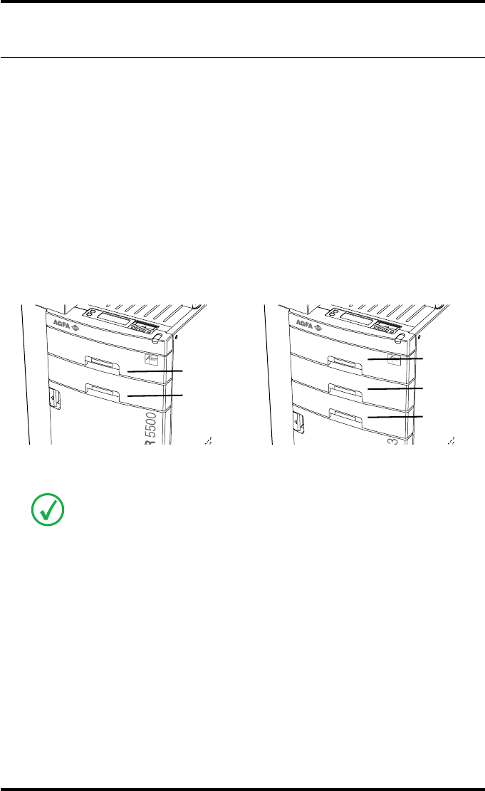
The Drystar 5500/5503 Reference manual is intended for both the
Drystar 5500 and the Drystar 5503 printers.
The only difference between both printers is the number of input trays:
•The Drystar 5500 is fitted with two input trays,
named Upper input tray and Lower input tray.
•The Drystar 5503 is fitted with three input trays,
named Upper input tray, Middle input tray and Lower input tray.
The operation is identical for each input tray.
This manual only deals with the Drystar 5500 printer, equipped with two trays.
As the operation of the Middle input tray is identical to the Upper and Lower input
tray, this manual is also applicable for the Drystar 5503 printer equipped with
three trays.
Upper
Lower
Upper
Middle
Lower
82900H EN 20071108
DRYSTAR 5500/5503 REFERENCE MANUAL
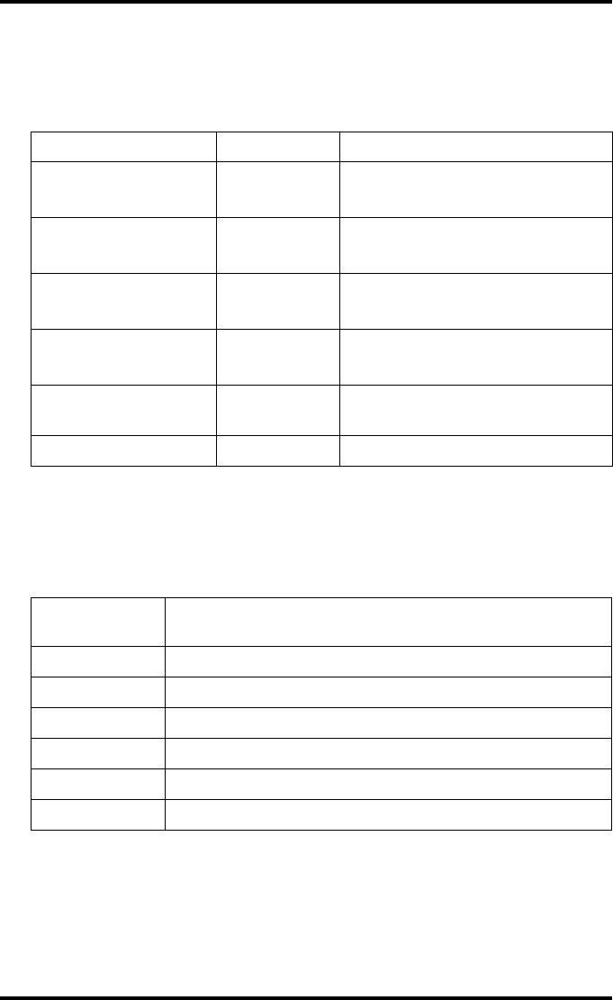
ABC ordering codes
The table below lists the ordering codes for the Drystar 5500, Drystar 5503
and possible options.
Available Software versions
The table below lists the available software versions and the type of printer
they require:
Description ABC code Remark
Drystar 5500 EJ7SX •standard two trays
• A#sharp technology is included
Drystar 5503 ESKZV •standard three trays
• A#sharp technology is included
Mammo option for
Drystar 5500 ER3N3 • applicable for Drystar 5500
• A#sharp technology is included
Mammo option for
Drystar 5503 ER3O5 • applicable for Drystar 5503
• A#sharp technology is included
A#sharp kit for
Drystar 5500 ERA2O applicable for Drystar 5500 with a
software version lower then 3.00
Cleaning roller tissue EQU6Y
Software
version (SW) Printer
3.x supports Drystar 5500
4.0.x supports Drystar 5500
4.2.x supports Drystar 5500 (RoHs compliant)
5.0.x supports Drystar 5503
5.2.x supports Drystar 5503 (RoHs compliant)
6.x supports Drystar 5500 and 5503 (RoHs compliant)

Introducing the
Drystar 5500
This chapter introduces the Drystar 5500 to the user and
draws attention to important safety precautions.
TDrystar 5500 features
TSafety precautions
TSecurity precautions
TSafety compliance
TPrivacy and security
TOperating modes
TControl modes (local and remote)
TThe local user interface
TSwitching on the Drystar 5500
TCooling down the Drystar 5500
TSwitching off the Drystar 5500
Chapter 1

10 2900H EN 20071108Introducing the Drystar 5500
DRYSTAR 5500/5503 REFERENCE MANUAL
Drystar 5500 features
The Drystar 5500 is a dry digital printer for producing diagnostic images. It
can print multiple formats (8x10”, 10x12”, 11x14”, 14x14”, and 14x17”) of
blue-based and clear-based film and offers crisp, dense grayscale images. The
Drystar 5500 can be used for general radiography and optionally for the
mammography application. It is designed for high-throughput and for use as a
central printer.
The Drystar 5500 offers the following features:
QDry technology for printing diagnostic quality hard copies in full daylight offers
important advantages: no chemistry, no wet processing, simple cleaning proce-
dures, no time-consuming adjustments, no darkroom and no chemical disposal
costs. The consumables can be loaded in full daylight.
QWith its compact design, the Drystar 5500 needs little work space and allows
easy customer access. Maintenance and service activities are reduced to the
minimum.
QThe direct thermal printing system provides grayscale images with laser-like
quality: 508 dots per inch resolution, each pixel with a 14 bit contrast resolution
and an average optical density of 3.0 (DT 2 C) and 3.2 (DT 2 B) for general radi-
ography applications and 3.8 for the optional mammography application (if an
X-Rite 310 densitometer is used).
QThe built-in image spooling on hard disk assures a high throughput. Printing
time is kept to a minimum.
QMultiple film formats (8x10”, 10x12”, 11x14”, 14x14”, and 14x17”) can be used.
Any combination of two film formats can be used “on line”. Both input trays can
be adjusted for all film formats.
QThe input trays of the Drystar 5500 are equipped with an RF-tag reader, which
automatically traces the films used in the printer and protects the printer when
detecting non-identified media.
QNumber of input trays.
The Drystar 5500 is delivered with 2 input trays. Both input trays can use
multiple format (8x10” up to 14x17”) films.
The Drystar 5500 is a DICOM-only network printer.
11
2900H EN 20071108 Introducing the Drystar 5500
DRYSTAR 5500/5503 REFERENCE MANUAL
QNumber of output trays
The Drystar 5500 is delivered with 4 output trays, which can be assigned to
modalities in any combination.
QA Quality Control software module is available for the Key-operator. The QC
procedure for general radiography applications has been designed to comply
with the grayscale reproduction constancy test, according to the international
standard IEC 1223-2-4. For more information, refer to ‘Quality control for gen-
eral radiography applications (DT 2 B & DT 2 C)’ on page 141. The QC proce-
dure for the optional mammography application has been designed to comply
with the Mammography Quality Standards Act (MQSA) of the FDA. For more
information, refer to ‘Quality control for mammography application
(DT 2 Mammo) (optional)’ on page 153.
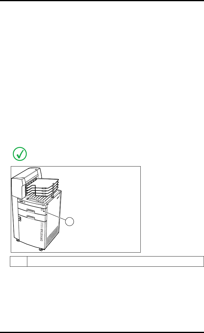
QIntegrated A#sharp technology
A#sharp is a technology that enhances image sharpness for the Drystar 5500.
An A#sharp label on the upper tray shows that the imager has been upgraded
with this technology.
The A#sharp technology is present in Software version 3.00 and higher.
1A#Sharp label
1

12 2900H EN 20071108Introducing the Drystar 5500
DRYSTAR 5500/5503 REFERENCE MANUAL
Network features
QThe modular design offers optimal application to your specific networking
requirements.
In a network configuration, the Drystar 5500 is fully compatible with Agfa’s
diagnostic imaging systems, including the ADC Compact and ADC Quality
System software, the Paxport and the entire line of Impax Review Systems,
Storage Stations and Transmitting Stations.
QThe functionality of the Drystar 5500 is completely controlled via the network.
QYou can control the working of the Drystar 5500 via the local keypad or via a
remote PC featuring a browser functionality.
Customizable features
QNumber of output trays.
The Drystar 5500 is delivered with 4 output trays and a sorter.
QConsumables.
The Drystar 5500 can handle DRYSTAR DT 2 B and DRYSTAR DT 2 C
consumables (both are general radiography film types) in multiple formats
(8x10” up to 14x17”) and optionally DRYSTAR DT 2 Mammo (mammograpy
film type) consumables, available in the formats 8x10”, 10x12” and 11x14”.
Software license information
QThe Drystar 5500 printer uses software developed by the Apache Software
Foundation (http://www.apache.org/licenses/LICENSE).
13
2900H EN 20071108 Introducing the Drystar 5500
DRYSTAR 5500/5503 REFERENCE MANUAL
Safety precautions
When operating or maintaining the Drystar 5500, always observe the
following safety guidelines:
•Have electrical or mechanical defects repaired by skilled personnel only!
•Do not override or disconnect the integrated safety features.
•Ventilation openings may not be covered.
•Always switch off the Drystar 5500 and disconnect the power cord from
the outlet before carrying out any maintenance work.
Always take into account the markings provided on the inside and outside of
the printer. A brief overview of these markings and their meaning is given
below.
The Drystar 5500 must only be operated according to its specifications and its
intended use. Any operation not corresponding to the specifications or intended use
may result in hazards, which in turn may lead to serious injuries or fatal accidents
(for example electric shocks). AGFA positively will not assume any liability in these
cases.
All images created using any image technology can show artifacts which could be
mixed up with diagnostic relevant information. If there is any doubt that the
diagnostic information could not be absolutely true, additional investigations must
be performed to get a clear diagnostic.
Film jam removal or Cleaning the printer thermal head can be done without
switching the power off. Nevertheless, care should be taken and the following
instructions should be respected:
Safety warning, indicating that the Drystar 5500 manuals should be
consulted before making any connections to other equipment. The
use of accessory equipment not complying with the equivalent safety
requirements of this printer may lead to a reduced level of safety of
the resulting system. Consideration relating to the choice of
accessory equipment shall include:
• Use of the accessory equipment in the patient vicinity,
• Evidence that the safety certification of the accessory equipment
has been performed in accordance with the appropriate IEC 601-1
and IEC 601-1-2 harmonized national standard.
In addition all configurations must comply with the medical
electrical systems standard IEC 601-1-2. The party that makes the
connections acts as system configurator and is responsible for
complying with the systems standard.
If required contact your local service organization.
14 2900H EN 20071108Introducing the Drystar 5500
DRYSTAR 5500/5503 REFERENCE MANUAL
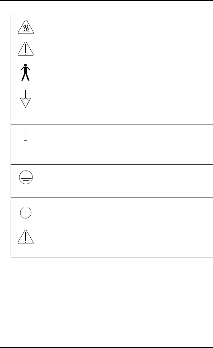
Caution hot:
Keep hands clear from the thermal print head.
In order to reduce the risk of electric shock, do not remove any
covers.
Type B equipment:
Indicates that the Drystar 5500 complies with the limits for type B
equipment.
Supplementary protective earth connector:
Provides a connection between the Drystar 5500 and the potential
equalization busbar of the electrical system as found in medical
environments. This plug should never be unplugged before the
power is turned off and the power plug has been removed.
Intergrounding connector:
Provides a connection between the printer and other equipment
which might exhibit minor ground potential differences. These
differences may degrade the quality of communication between
different equipment. Never remove connections to this terminal.
Protective earth (ground):
Provides a connection between the printer and the protective earth
of the mains. Do not remove this connection, because this will have a
negative influence on the leakage current.
Power button:
Note that the power cord has to be disconnected from the wall outlet
in order to disconnect the unit entirely from the mains.
Precautions for use in USA only:
Make sure that the circuit is single-phase center-tapped, if the printer
is connected to a 240 V/60 Hz source instead of a 120 V/60 Hz
source.
15
2900H EN 20071108 Introducing the Drystar 5500
DRYSTAR 5500/5503 REFERENCE MANUAL
Transport after installation
Before moving the printer, always switch off the machine. The user has to be
very cautious concerning stability, when moving the printer. When doing this,
he has to take into account the condition and the structure of the subsoil,
obstructions and slopes. Also the user has to make sure that the brakes are
loose. The appliance can only be transported with all covers closed. The
appliance may not be transported continuously from one location to the other.
Waste disposal and environmental regulations
To prevent injuries, lock the brakes when the Drystar 5500 is in place at
the right location.
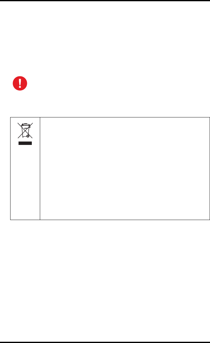
This symbol on the product, or in the manual and in the warranty,
and/or on its packaging indicates that this product shall not be
treated as household waste.
Instead it shall be handled over to the applicable collection point for
the recycling of electrical and electronic equipment. For more
detailed information about take-back and recycling of this product,
please contact your local Agfa service organization.
By ensuring this product is disposed of correctly, you will help
prevent potential negative consequences for the environment and
human health, which could otherwise be caused by inappropriate
waste handling of this product. The recycling of materials will help to
conserve natural resources. If your equipment contains easy
removable batteries or accumulators please dispose these separately
according to your local requirements.

16 2900H EN 20071108Introducing the Drystar 5500
DRYSTAR 5500/5503 REFERENCE MANUAL
Restriction of the Use of Certain Hazardous Substances (RoHS)
The RoHS (Restriction of Hazardous Substances)
Directive No 2002/95/EC of the European Union focuses on the
restriction of the use of certain hazardous substances in electrical
and electronic equipment.
Member States of the European Union (EU) shall ensure that, from 1
July 2006, new electrical and electronic equipment put on the
market (EU countries), does not contain the following substances
above specified concentrations at the homogeneous material level:
• Cadmium (0.01%)
•Hexavalent chromium (0.1%)
•Lead (0.1%)
•Mercury (0.1%)
• Polybrominated biphenyls (PBB) (0.1%)
• Polybrominated diphenyl ethers (PBDE) (0.1%)
At the date of preparation of this manual, Medical Devices are
exempted of the RoHS Directive.
However Agfa HealthCare is committed to meet the requirements of
the European RoHS Directive in case the exemption is cancelled.
If there is a RoHS label at the rear of the printer it means that the
printer is RoHS compliant and does not contain the above listed
substances above the mentioned concentrations at the homogeneous
material level.
In case of questions or more detailed information do not hesitate to
contact your local sales organization.

17
2900H EN 20071108 Introducing the Drystar 5500
DRYSTAR 5500/5503 REFERENCE MANUAL
Security precautions
CAUTION (U.S.A. only): In accordance with U.S. Law, this device can only be
sold to or ordered by a licensed physician.
Printed images should be treated as patient records and should only be
viewed by authorized personnel.
It is good practice not to delete images from the modality, until they are
correctly printed.
It is advisable to do a reprint when film artifacts are present in the image.
In case of general image quality degradation, please refer to ‘Maintaining
image quality and resolving Image quality problems’ on page 220.

18 2900H EN 20071108Introducing the Drystar 5500
DRYSTAR 5500/5503 REFERENCE MANUAL
Safety compliance
EMC issues
•USA: This equipment has been tested and found to comply with the limits
for a class A digital device, pursuant to part 15 of the FCC rules. These
limits are designed to provide reasonable protection against harmful
interference when the equipment is operated in a commercial
environment. This equipment generates, uses, and can radiate radio
frequency energy and, if not installed and used in accordance with the
Reference manual, may cause harmful interference to radio
communications. Operation of this equipment in a residential area is likely
to cause harmful interference in which case the user will be required to
correct the interference at its own expense.
•If required, contact your local service organization.
•Canada: This class A digital apparatus meets all requirements of the
Canadian Interference-Causing Equipment Regulations.
•EC: This is a class A product. In a domestic environment this product may
cause radio interference in which case the user may be required to take
adequate measures.
Compliances
The Drystar 5500 has been tested and found to comply with the following
international standards and regulations:
•The Medical Devices Directive 93/42/EEC
•CFR Part 21
•FDA 510K, FDA Part 820 Good manufacturing Practice for Medical devices
•The Quality Control test procedure for general radiography applications
(refer to ‘Quality control for general radiography applications (DT 2 B &
DT 2 C)’ on page 141 complies with the grayscale reproduction constancy
test, according to the international standard IEC 1223-2-4.
•The Quality Control test procedure for the optional mammography
application (refer to ‘Quality control for mammography application
(DT 2 Mammo) (optional)’ on page 153) complies with the Mammography
Quality Standard Act (MQSA) of the FDA.

19
2900H EN 20071108 Introducing the Drystar 5500
DRYSTAR 5500/5503 REFERENCE MANUAL
Safety standards
•IEC 60601-1
•EN 60601-1
•UL 2601-1
•CSA 22.2 No. 601.1-M90
•GB4943
Radio-interference regulations (interference suppression)
•FCC Rules 47 CFR part 15 subpart B
•FCC Rules 47 CFR part 15 subpart C
•IEC 60601-1-2
•CISPR 11, class A
•CISPR 22, class A
•IEC 61000-4-3
•IEC 61000-4-4
•IEC 61000-4-5
•IEC 61000-4-6
•IEC 61000-3-2
•IEC 61000-3-3
•IEC 61000-4-11
•ETSI 300330
•GB9254, Class A
•GB17625.1
Labels
The Drystar 5500/5503 carries the CE, TÜV, cULus and CCC labels.
20 2900H EN 20071108Introducing the Drystar 5500
DRYSTAR 5500/5503 REFERENCE MANUAL
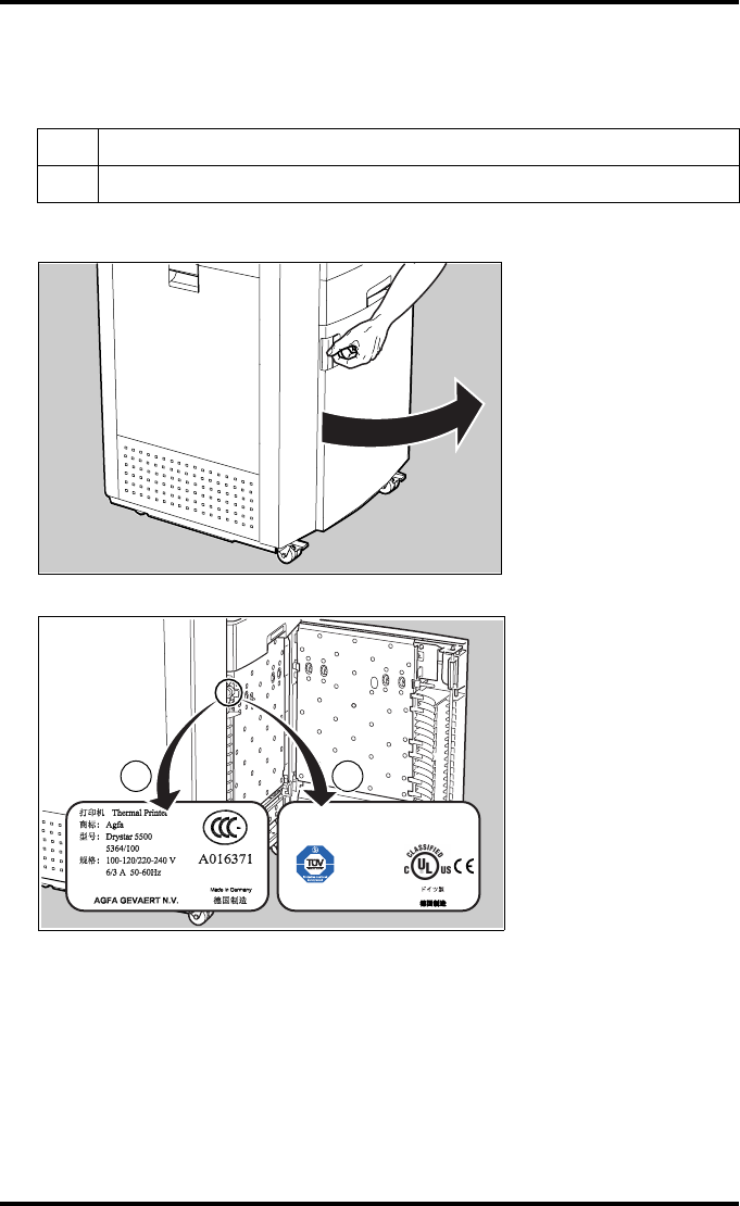
Labels Drystar 5500:
The following labels are located behind the front door:
•Open the front door.
•The labels are visible inside the printer.
1CCC label
2CE, TÜV and cULus labels
Type5364/100Date:MM.JJJJ
F-Nr.xxxxx MFRI.D.:P
100-120/220-240V6/3A50-60Hz
AGFAGEVAERTN.V.
MadeinGermany
MEDICALELECTRIC
EQUIPMENT
WITHRESPECTTOELECTRIC
SHOCK,FIRE,ANDMECHANICAL
HAZARDSONLYIN
ACCORDANCEWITHUL2601-1/
CAN/CSAC22.2NO.601.1
9F03
1 2
21
2900H EN 20071108 Introducing the Drystar 5500
DRYSTAR 5500/5503 REFERENCE MANUAL
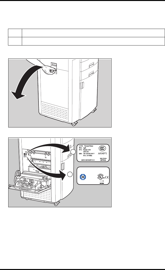
Labels Drystar 5503:
The following labels are located behind the drum compartment door:
•Open the drum compartment door by pulling its handle.
•The labels are visible inside the printer.
Power cord regulations
•Use attached power cord set to the product.
•Do not use attached power cord set for other electric equipment.
1CCC label
2CE, TÜV and cULus labels
Type 5364/100 Date: MM.JJJJ
F-Nr. xxxxx MFR I.D.: P
100-120/220-240V 6 / 3A 50-60Hz
AGFA GEVAERT N.V.
Made in Germany
MEDICAL ELECTRIC
EQUIPMENT
WITH RESPECT TO ELECTRIC
SHOCK, FIRE, AND MECHANICAL
HAZARDS ONLY IN
ACCORDANCE WITH UL2601-1 /
CAN/CSA C22.2 NO.601.1
9F03
1
2

22 2900H EN 20071108Introducing the Drystar 5500
DRYSTAR 5500/5503 REFERENCE MANUAL
Privacy and security
Within the healthcare industry, several standardization efforts are ongoing as
a response to Privacy and Security legislation and regulations. The purpose of
this standardization for hospitals and vendors is to enable information
sharing, interoperability and to support the workflow of hospitals in a
multiple vendor environment.
In order to allow hospitals to comply with HIPAA regulations (Health
Insurance Portability and Accountability Act) and to meet the IHE standards
(Integrated Healthcare Enterprise) some security features are included in the
user interface of the Drystar 5500 (available via the web pages only: under
‘Security tools’. Refer to Chapter 4, ‘Controlling the Drystar 5500 via a remote
PC (with browser)’):
•Product Authentication: HIPAA supported products that communicate with
DICOM use the Transport Layer Security (TLS) protocol. The TLS
protocol uses public key certificates for client and server authentication
(X.509).
•Product Accountability: HIPAA supported products require some level of
user and system activity to be recorded. As a consequence of these actions,
audit records are to be sent to and observed at an Audit Record Repository
(ARR).
•Product User Authentication: 'User Authentication' of HIPAA products
involves password protection for access to User, Key operator, Service
Security/ Administrator and other user interfaces that allow access to
protected health information (PHI). These interfaces include all user
keypads, front panels displays and network connections.
The last two functions are available when access to the Administrator is
granted (i.e. when the Administrator password has been entered correctly).

23
2900H EN 20071108 Introducing the Drystar 5500
DRYSTAR 5500/5503 REFERENCE MANUAL
Node authentication, certificates and Certification Authority
Each device - connected to a network - will receive a unique identifier: the
X.509 certificate, a digital passport. Any device on the network is only
allowed to communicate with another node of which it is holding the
certificate in a ‘communication allowed’ table.
A Certification Authority (CA) is responsible for creating a certificate. The CA
can be the hospital, Agfa or a third party.
This CA distributes the certificate to the hospital security responsible or
service technician, who for his part:
•Imports the device certificate, created by the CA.
•Imports the certificates of all peer devices with which communication is
authorized, i.e. creates the list of ‘communication allowed’ device
certificates.

24 2900H EN 20071108Introducing the Drystar 5500
DRYSTAR 5500/5503 REFERENCE MANUAL
Operating modes
The Drystar 5500 can be operated in five modes: operator mode, Key-
operator mode, service mode, specialist mode, and administrator mode.
Operator mode
The operator mode groups all basic functions which are aimed at
radiographers without special technical skills:
•Producing diagnostic usable hardcopies;
•Loading consumables;
•Ensuring normal operation of the printer.
All functions of the operator mode are described in both User and Reference
manuals. Refer to Chapter 2, ‘Basic operation (operator mode)’.
Acces is possible via the local keypad and via a connected remote PC
(password protected).
Key-operator mode
The Key-operator mode groups advanced functions which are aimed at
technically skilled operators such as X-ray operators, network managers and
service and hospital technicians.
The Key-operator mode is menu-driven. The Key-operator functions are
described in the Reference manual only. Refer to Chapter 3, ‘Advanced
operation (Key-operator mode)’.
Acces is possible via the local keypad and via a connected remote PC
(password protected).
Service mode
The service mode functions are reserved for trained service personnel. The
service mode is password protected.
Acces is possible via the local keypad and via a connected remote PC. In both
cases the service personnel needs a password.

25
2900H EN 20071108 Introducing the Drystar 5500
DRYSTAR 5500/5503 REFERENCE MANUAL
Specialist mode
The specialist mode functions are reserved for trained service personnel of
the Agfa Customer Support Center. The specialist mode is password protected
and is only accessible by browser via a remote PC.
Administrator mode
The Administrator mode functions are reserved for the System Administrator.
The Administrator mode is password protected and is only accessible by
browser via a remote PC. Refer to ‘Privacy and security’ on page 22.
26 2900H EN 20071108Introducing the Drystar 5500
DRYSTAR 5500/5503 REFERENCE MANUAL
Control modes (local and remote)
You can control the working of the Drystar 5500 via the local keypad or via a
network browser based remote PC.
The table below gives an overview of the operating modes you can access
locally or via the remote PC.
The manual describes the controlling of the Drystar 5500 via the keypad.
When controlling the Drystar 5500 via a remote PC, the menus are structured
in the same way. Refer to Chapter 4, ‘Controlling the Drystar 5500 via a remote
PC (with browser)’.
Local Password
protected Remote Password
protected
Operator mode No Operator mode Yes
Key-operator mode No Key-operator mode Yes
Service mode Yes Service mode Yes
Specialist mode No access Specialist mode Yes
Administrator mode No access Administrator mode Yes
27
2900H EN 20071108 Introducing the Drystar 5500
DRYSTAR 5500/5503 REFERENCE MANUAL
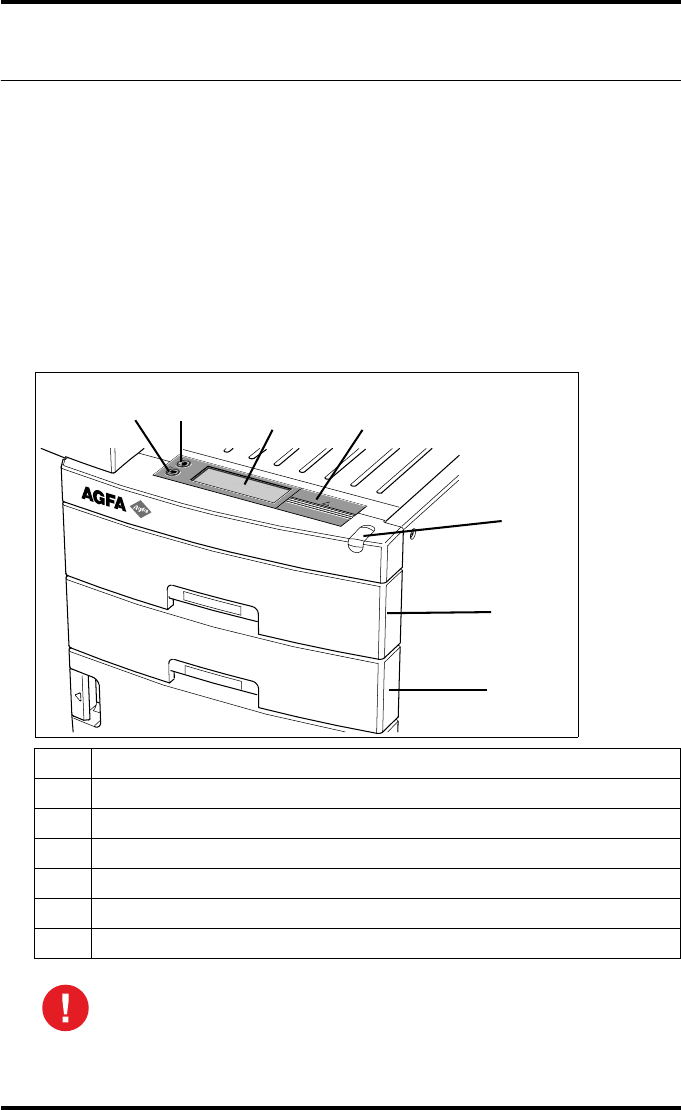
The local user interface
The Drystar 5500 interfaces with the user via the following controls:
•Power button;
•Unlock button;
•a keypad and a display;
•a status indicator LED;
•audio signals.
Overview of user interface controls:
1Unlock button
2Power button
3Display
4Keypad cover
5 Status indicator LED
6Film input tray (Upper input tray)
7Film input tray (Lower input tray)
Never try to open the printer when the Drystar 5500 is busy printing a
film. Always follow the instructions on the display!
1234
5
6
7
28 2900H EN 20071108Introducing the Drystar 5500
DRYSTAR 5500/5503 REFERENCE MANUAL
The status indicator LED
At the right side of the display, a LED indicates the status of the Drystar 5500:
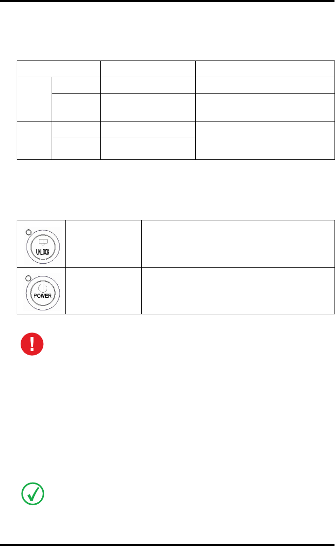
The control buttons
Two control buttons have been provided:
Audio signals
The Drystar 5500 gives status information via beeps. The length of the beep
indicates the response of the system to a key command.
•A short beep means that Drystar 5500 has accepted the key command and
is starting the operation.
•A long beep means that you have pressed a non-active key or that the
Drystar 5500 has rejected the key command.
Color / Light Status Action
Green
Constant Ready (stand-by) Proceed.
Blinking Busy or in Key-
operator mode Wait.
Red
Blinking Warning status Check the display for messages.
Refer to ‘Checking the status
indicator LED’ on page 195.
Constant Error status
Unlock button • To safely unlock the printer for accessing the
input trays or opening the covers.
Power button • To power on or off the printer.
Do NOT press the Power button without first following the procedure to
stop printing when the Drystar 5500 is busy printing a film. Refer to
‘Switching off the Drystar 5500’ on page 36.
Certain conditions can cause an interval beep. An interval beep accompanies an
error or warning message. Refer to ‘Troubleshooting checklist’ on page 194.
29
2900H EN 20071108 Introducing the Drystar 5500
DRYSTAR 5500/5503 REFERENCE MANUAL
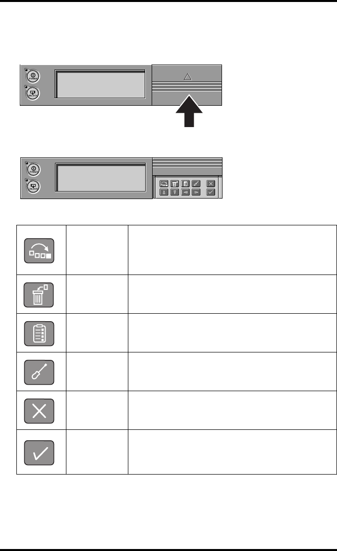
The keypad
To access the keypad, push the keypad cover backward.
The keypad is located under the keypad cover.
The Drystar 5500 keypad features the following keys:
Emergency
key
To rearrange the print queue: emergency jobs can
be placed at the top of the queue to be printed with
priority. Refer to ‘Assigning emergency priority’ on
page 41.
Delete key To delete print jobs. Jobs that are deleted will not be
printed. Refer to ‘Deleting print jobs’ on page 42.
Key-
operator key
To access the advanced functions of the Key-
operator mode. Refer to Chapter 3, ‘Advanced
operation (Key-operator mode)’.
Service key To access service-level functions. Reserved for
trained service personnel.
Escape key To quit the current function or exit a menu without
saving modifications.
Confirm key
(In Key-operator mode)
• To select a menu.
• To accept an entry in a menu.
30 2900H EN 20071108Introducing the Drystar 5500
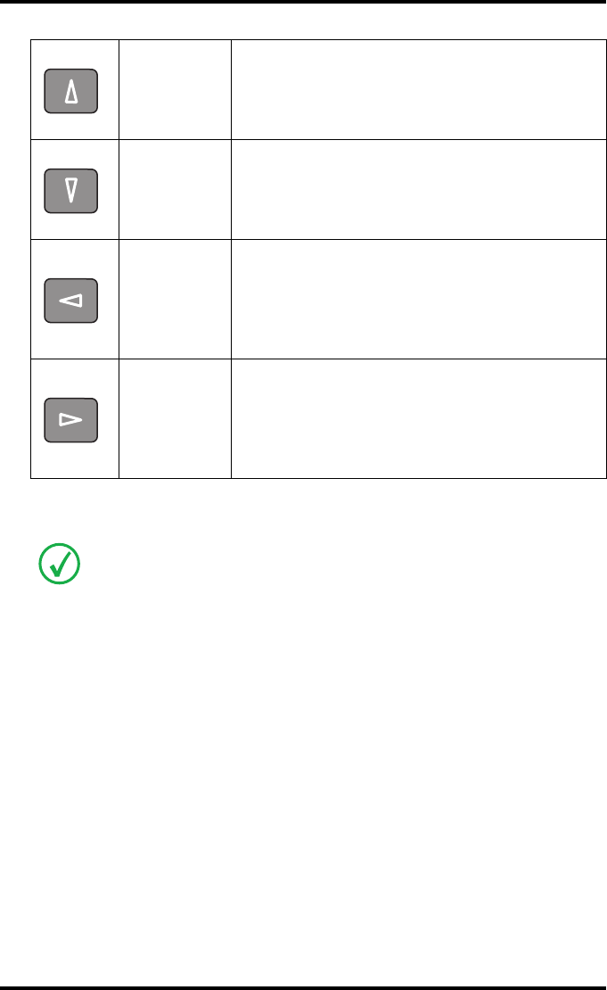
DRYSTAR 5500/5503 REFERENCE MANUAL
Up key
• To move the cursor to the previous entry field.
• To scroll upwards.
• To increment the number in a(n)
(alpha)numerical entry field.
Down key
• To move the cursor to the next entry field.
• To scroll downwards.
• To decrement the number in a(n)
(alpha)numerical entry field.
Left key
• To scroll backwards through multiple choices
within a field.
• To move the entry position in a(n)
(alpha)numerical entry field from right to left.
• To toggle between values in a field.
Right key
• To scroll forwards through multiple choices
within a field.
• To move the entry position in a(n)
(alpha)numerical entry field from left to right.
• To toggle between values in a field.
You can press and hold down an arrow key to scroll quickly through a list or a
menu.
31
2900H EN 20071108 Introducing the Drystar 5500
DRYSTAR 5500/5503 REFERENCE MANUAL
The display
The Drystar 5500 control panel has a backlit LCD display. We distinguish two
panel types depending on the selected language:
•a backlit LCD display with 8 lines for Western languages (e.g. Dutch,
French, Portuguese, Swedisch, ...).
•a backlit LCD display with 4 lines for all other languages (e.g. Greek,
Chinese, Korean, Polish,...).
Whether a display is translated or not depends on the operating mode.
Operator mode
In operator mode, appropriate information is displayed, in accordance with
the status of the printer.
The operator basic screen looks as follows, indicating that the Drystar 5500 is
ready for operation and that no job is currently being executed.
Contact Agfa for the latest Drystar 5500 language availability status.
32 2900H EN 20071108Introducing the Drystar 5500
DRYSTAR 5500/5503 REFERENCE MANUAL
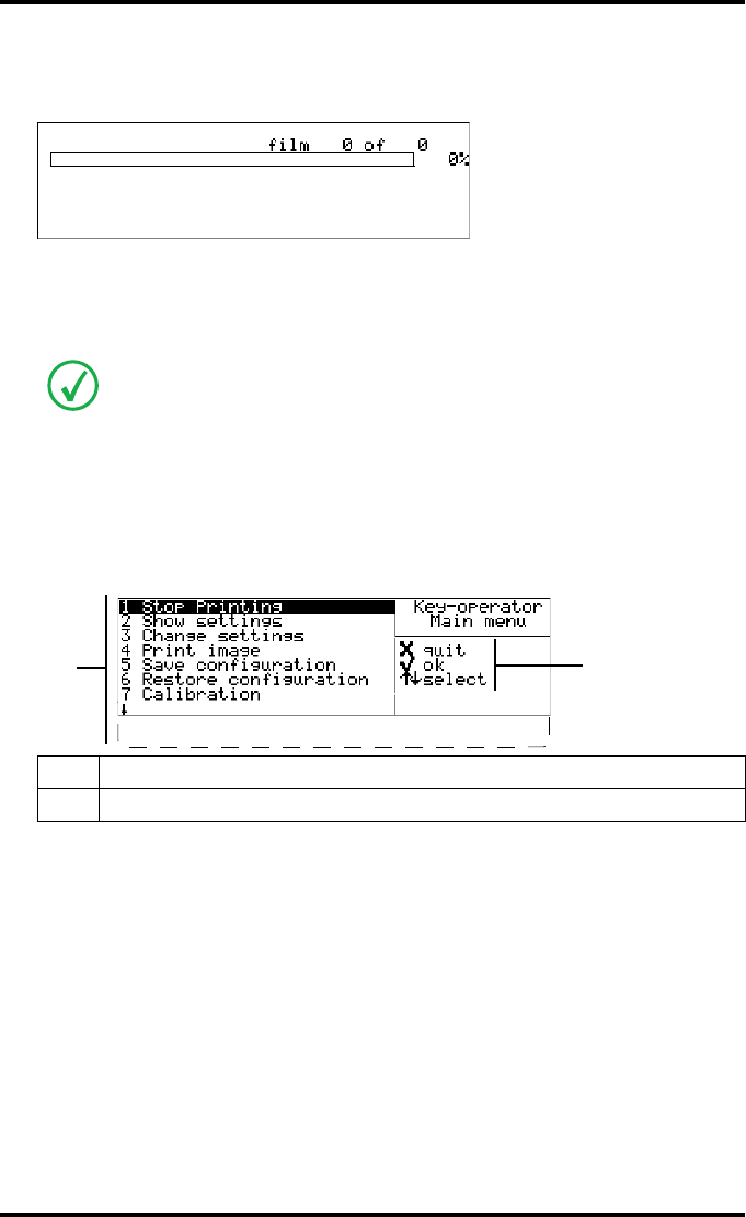
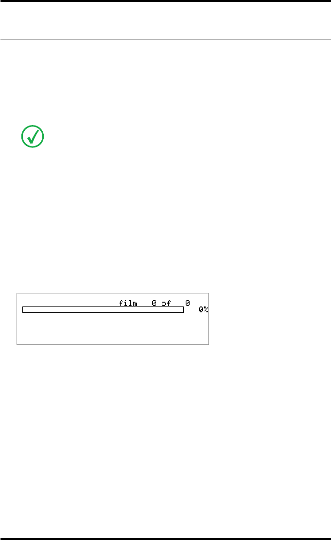
During printing, calculation and other processes, as the printer is busy with at
least one job, the Print queue screen is displayed:
•The progress indicator keeps the user informed of the progress of a
process (e.g., calculation of a bitmap, printing of a film, copying files). The
line is gradually filled from left to right, from 0% to 100% as the process
proceeds.
Refer to ‘Managing the print queue’ on page 39.
Key-operator mode
In Key-operator mode, operation is menu driven. The menu displays the Key-
operator functions and the active keys.
On the print queue screen the modality name defined during installation
(nickname) will be used to refer to the corresponding modality. In case no
nickname has been defined during installation, this AE-title will be used.
1Key-operator main menu functions
2Active keys
<Modality name> 10:21:34 PRINTING
1 2
<Modality name> 10:21:34 CALCULATING
<Modality name> 11:35:27 WAITING
<Modality name> 11:54:02 WAITING
8 Installation
9 Quality Control
2
1

33
2900H EN 20071108 Introducing the Drystar 5500
DRYSTAR 5500/5503 REFERENCE MANUAL
Data entry
When entering numerical or alphanumerical data, always adhere to the
following principles:
•Only (alpha)numerical data can be entered.
•During the data entry, the field is displayed in reverse mode.
•Increment the number in a(n) (alpha)numerical entry field by pressing the
Up key. Transition from 9 to 0 of one figure will also increment the next
figure to the left, respecting the valid limits of the range.
•Decrement the number in a(n) (alpha)numerical entry field by pressing
the Down key. Transition from 0 to 9 of one figure will also decrement the
next figure to the left, respecting the valid limits of the range.
•Move the entry position in a(n) (alpha)numerical entry field from right to
left by pressing the Left key.
•Move the entry position in a(n) (alpha)numerical entry field from left to
right by pressing the Right key.
•Press and hold down a key to repeat arrow key actions.
•To accept an entry in a menu, press the Confirm key.
•A short beep acknowledges and terminates the entry.
•The Drystar 5500 will sound a long beep if you press a key that is not to be
used at that moment.
34 2900H EN 20071108Introducing the Drystar 5500
DRYSTAR 5500/5503 REFERENCE MANUAL
Switching on the Drystar 5500
Follow the procedure below to ensure proper start-up of the Drystar 5500 and
to check that everything is working correctly.
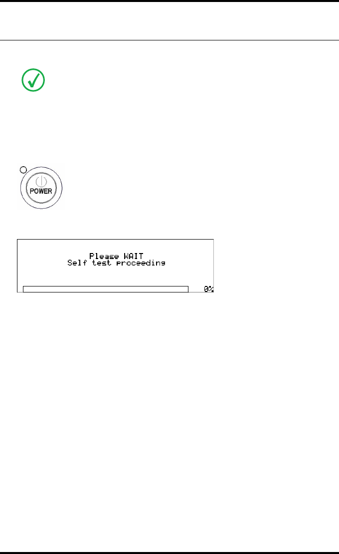
1Check that the power cord is plugged in and then switch on the printer by
pressing the Power button.
On the display, the following message is displayed. After a short while, a progress
indicator will show the proceeding of the self test.
Before switching on the Drystar 5500, read the safety instructions. Refer to
‘Security precautions’ on page 17.
35
2900H EN 20071108 Introducing the Drystar 5500
DRYSTAR 5500/5503 REFERENCE MANUAL
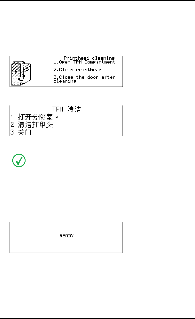
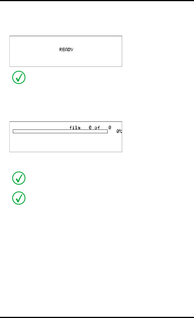
2The printer is ready for operation:
•If, on the front panel display, the READY message is shown, the status
indicator LED is constant green.
•If, on the front panel display, the Print queue screen is shown, the status
indicator LED is green and blinking.
3Make sure that the printer is loaded with appropriate consumables.
It takes 11 minutes before the Drystar 5500 can start printing. After 6 minutes the
READY message appears and from then on you can send print jobs to the printer,
but it will take another five minutes for the printer head to heat up. When you send
print jobs to the Drystar 5500 during this five minutes, the printer will use that
time to calculate the print job and the display will inform you that the printer is
warming up.
Refer to page 46 for detailed information on loading films.
If the job status holds a warning or error indication. Refer to ‘Troubleshooting
checklist’ on page 194.
<Modality name> 10:21:34 PRINTING
1 2
<Modality name> 10:21:34 CALCULATING
<Modality name> 11:35:27 WAITING
<Modality name> 11:54:02 WAITING
36 2900H EN 20071108Introducing the Drystar 5500
DRYSTAR 5500/5503 REFERENCE MANUAL
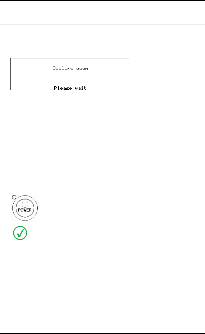
Cooling down the Drystar 5500
If owing to certain circumstances (e.g. extensive printing), the temperature
rises too much, the Drystar 5500 will cool down automatically. The cooling
down message will appaear on the display during the cooling down process.
Switching off the Drystar 5500
When you want to switch off the printer, it is recommended to follow the
procedure as described below, to make sure that any pending jobs are
correctly finished.
1Make sure that the pending jobs are correctly finished. If necessary, follow the
procedure to stop printing. Refer to ‘Stopping the printing process’ on page 59.
2Press the Power button to switch off the Drystar 5500.
In case the printer is ready, it shuts down immediately. Otherwise it can take up to
10 seconds to power down.

Basic operation
(operator mode)
This chapter will inform on how to manage the print queue,
how to print films with priority and how to load new films.
TOverview of operator functions
TManaging the print queue
TAssigning emergency priority
TDeleting print jobs
TAbout Drystar 5500 consumables
TLoading films
Chapter 2

38 2900H EN 20071108Basic operation (operator mode)
DRYSTAR 5500/5503 REFERENCE MANUAL
Overview of operator functions
This section focuses on the basic operating principles of the Drystar 5500.
After reading this chapter, the operator should be able to produce diagnostic
usable hardcopies. No special technical skills are required.
All basic operator functions can be activated directly by pressing a single key
on the keypad.
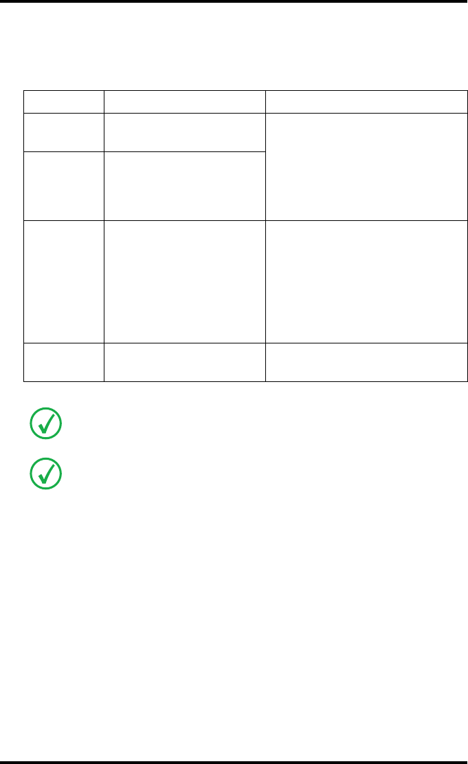
Function / Task Description Page
‘Managing the print queue’
Jobs that have been received are
put in a print queue, waiting to be
printed.
39
‘Assigning emergency priority’
To rearrange the order in which
jobs are waiting to be printed. Jobs
that have emergency priority are
placed on top of the print queue.
41
‘Deleting print jobs’
To remove print jobs from the print
queue. Print jobs that are deleted
will not be printed.
42
‘Loading films’ Instructions for loading new films
on the printer. 46
39
2900H EN 20071108 Basic operation (operator mode)
DRYSTAR 5500/5503 REFERENCE MANUAL
Managing the print queue
You can always check the status of the print jobs.
As long as the jobs are not yet submitted for printing (i.e. they are still in the
‘waiting’ status), you can assign emergency priority and delete individual
print jobs.
Checking the print queue
If jobs have been transmitted from the network to the Drystar 5500, they are
put in the print queue on a first in, first out schedule. New jobs that are added
to the queue get the ‘waiting’ status.
As soon as the last film of a job is ejected in the output tray, the next job that
has been calculated will be put in printing status.
Example of the Print queue screen:
•The first line shows information on the job that is currently being printed:
modality name, a nickname (if defined), time of receipt of the job and the
job status.
•The second line shows how many films are to be printed for the current job,
and also what film from that total is currently being printed.
•On the third line you can watch the progress of the printing process. The
progress indicator is gradually filled from left to right, from 0% to 100% as
the process is completed. If no job is being printed, the progress indicator
will show the proceeding of the calculation process of the next job.
Keep in mind that one print job can hold several films to be printed. In accordance
with the acquisition modality used, and the actual settings, films can be grouped in
a folder to be submitted as one print job for the Drystar 5500. Refer to the User
manual of the acquisition modality for more information.
<Modality name> 10:21:34 PRINTING
1 2
<Modality name> 10:21:34 CALCULATING
<Modality name> 11:35:27 WAITING
<Modality name> 11:54:02 WAITING
40 2900H EN 20071108Basic operation (operator mode)
DRYSTAR 5500/5503 REFERENCE MANUAL
The other lines give information on the jobs that are still waiting in the print
queue. A description of the possible status of each job is listed in the table
below:
Status Description Action
Printing Printing of this job is in
progress.
Wait.
Calculating
The necessary calculations
are being made before
printing of the job can be
started.
Waiting
The job has been put in the
print queue, but no
processing is yet being
done.
Wait.
• To put emergency jobs on top of
the queue, refer to ‘Assigning
emergency priority’ on page 41.
• To remove jobs from the queue,
refer to ‘Deleting print jobs’ on
page 42.
Media size
indication
No compatible media are
loaded for the print job.
Make sure the correct media are
loaded.
On the print queue screen the modality name defined during installation
(nickname) will be used to refer to the corresponding modality. In case no
nickname has been defined during installation, this AE-title will be used.
If the job status holds a warning or error indication, refer to ‘Error messages while
the printer starts up’ on page 218.
41
2900H EN 20071108 Basic operation (operator mode)
DRYSTAR 5500/5503 REFERENCE MANUAL
Assigning emergency priority
You can assign emergency priority to jobs that need to be printed with
urgency. Jobs that are marked for priority handling are placed at the top of
the print queue for immediate processing. Emergency jobs will be printed
before other jobs that were received previously. However, any pending jobs
that are already being calculated or scheduled for printing will be finished
first.
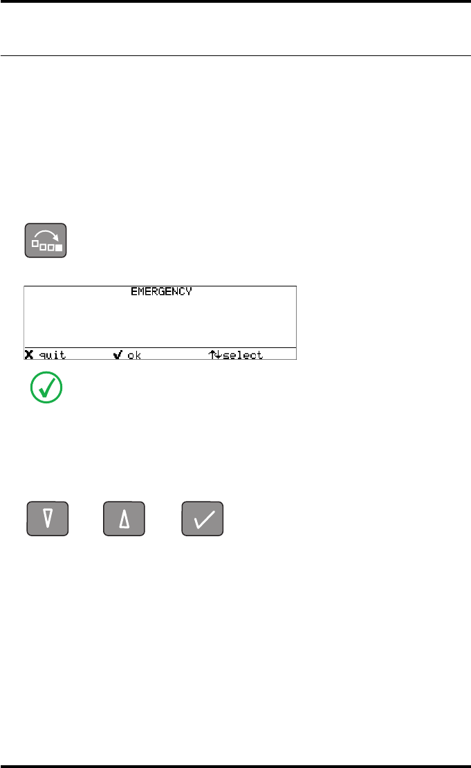
1On the keypad, press the Emergency key.
The Emergency printing screen is displayed:
You can press the Escape key to return to the previous menu without making changes
in the job order (‘Quit’).
2Press the Down and Up keys to scroll through the jobs and press the Confirm
key to select the job that must be printed with emergency priority.
Printing will be resumed in accordance with the changed queue order.
Only the jobs that have the ‘waiting’ status are displayed. Print jobs which already
have an emergency status are blinking.
<Modality name>18-01-200511:07:18
<Modality name>18-01-200511:07:36
42 2900H EN 20071108Basic operation (operator mode)
DRYSTAR 5500/5503 REFERENCE MANUAL
Deleting print jobs
You can remove jobs from the print queue if they are in the ‘waiting status’.
Any pending jobs that are already being calculated or scheduled for printing
will be finished. Such jobs can not be deleted.
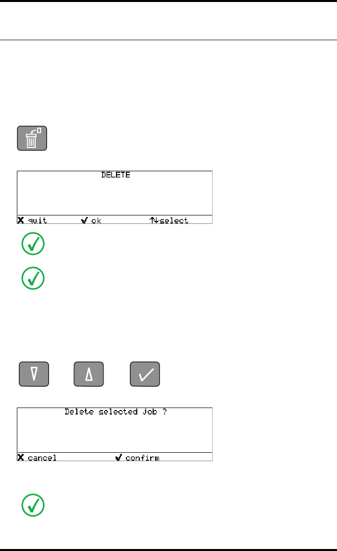
1On the keypad, press the Delete key.
The Delete print job screen is displayed:
You can press the Escape key to return to the previous menu without deleting print jobs
(‘Quit’).
2Press the Down and Up keys to scroll through the jobs and press the Confirm
key to select the job that must be deleted.
The Confirm delete screen is displayed.
You can press the Escape key to return to the previous menu without deleting print
jobs (‘Cancel’).
Only the jobs that have the ‘waiting’ status are displayed.
On the print queue screen the modality name defined during installation
(nickname) will be used to refer to the corresponding modality. In case no
nickname has been defined during installation, this AE-title will be used.
If you want to delete all jobs at once, press the up/down arrow keys to select ‘All
jobs’, followed by the Confirm key. Proceed with the next step.
<Modality name>18-01-200511:07:18
<Modality name>18-01-200511:07:36
<Modality name>18-01-200511:07:18

43
2900H EN 20071108 Basic operation (operator mode)
DRYSTAR 5500/5503 REFERENCE MANUAL
3Press the Confirm key to delete the print job.
Printing will be resumed. The job that has been deleted will not be printed.
44 2900H EN 20071108Basic operation (operator mode)
DRYSTAR 5500/5503 REFERENCE MANUAL
About Drystar 5500 consumables
The Drystar 5500 can handle blue-transparent DT 2 B, clear-transparent
DT 2 C (both for general radiography) and optionally (refer to ‘Options and
accessories’ on page 235) the blue-transparent DT 2 Mammo (for the
mammography application) films.
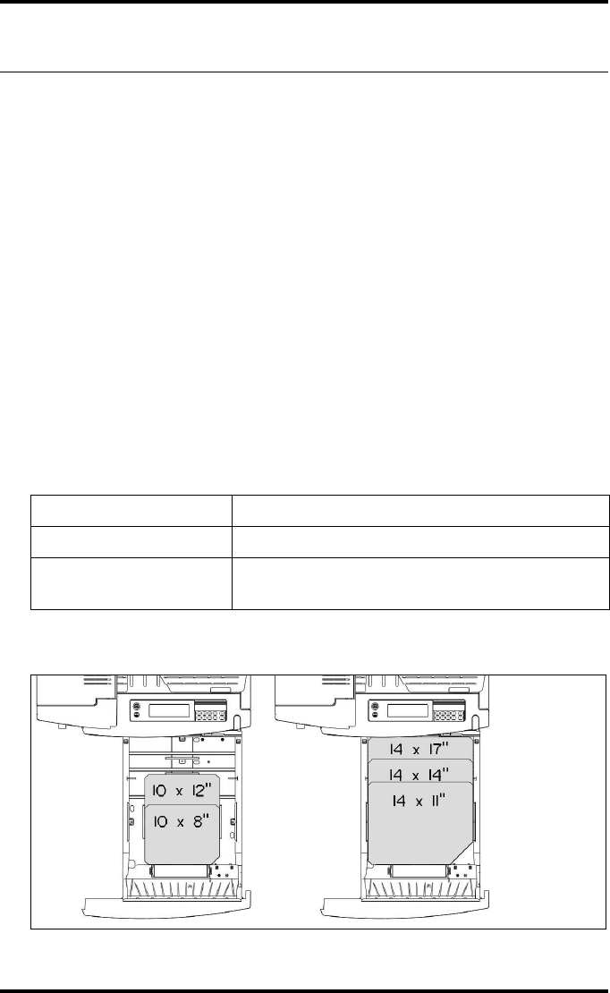
Available film formats for general radiography applications are 8x10”,
10x12”, 11x14”, 14x14”, and 14x17”. Available film formats for the
mammography application are 8x10”, 10x12” and 11x14”.
Both input trays can use all film formats.
The Key-operator can adjust the film size setting for both input trays.
For more information about adjusting film size setting, refer to ‘Changing the film
format of the trays’ on page 180.
Labeling the input trays
The following film types can be used:
The different formats are configurated in following way in a tray:
DRYSTAR DT 2 B 8x10”, 10x12”, 11x14”, 14x14”, and 14x17”
DRYSTAR DT 2 C 8x10”, 10x12”, 11x14”, 14x14”, and 14x17”
DRYSTAR DT 2 Mammo
(optional) 8x10”, 10x12” and 11x14”
45
2900H EN 20071108 Basic operation (operator mode)
DRYSTAR 5500/5503 REFERENCE MANUAL
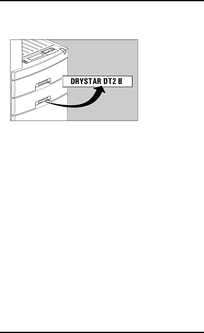
Appropriate labels have been applied on the input tray(s) by the service
personnel at installation of the printer, indicating the type of new film to be
loaded when the tray is empty.

46 2900H EN 20071108Basic operation (operator mode)
DRYSTAR 5500/5503 REFERENCE MANUAL
Loading films
Introduction
This section describes how to load the Drystar 5500 with appropriate films.
The Drystar 5500 can be loaded with 8x10”, 10x12”, 11x14”, 14x14” and
14x17” films.
The Drystar 5500 will inform you in several ways that an input tray is empty:
•An audible signal,
•the Status indicator LED is flashing (red color),
•the Unlock button LED is flashing,
•the display screen shows a message informing you that either the upper or
lower input tray is empty.
The film loading procedure is identical for both input trays. In the examples
below, we will assume that the lower input tray is to be loaded.
The Drystar 5500 can be loaded with new films in full daylight. Loading films is
easy and can be done in no time. Follow the procedures as described in this section.
The procedure is slightly different, depending on the fact wether the Drystar 5500
is printing/calculating or in the ready state.
When the printer is in the ready state, go to ‘When the Drystar 5500 is in the ready
state:’ on page 49.
Never load an additional film sheet or film sheets to a film pack in use.
Only load a new film pack when the current input tray is empty.
47
2900H EN 20071108 Basic operation (operator mode)
DRYSTAR 5500/5503 REFERENCE MANUAL
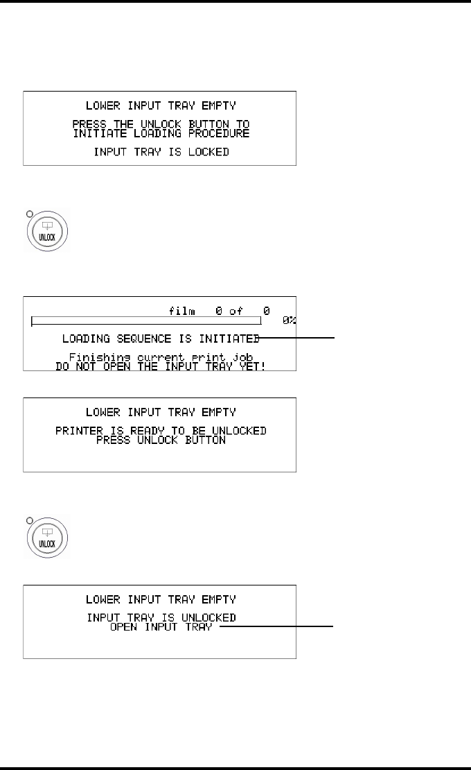
When the Drystar 5500 is printing or calculating:
1The display shows the following message:
2Press the Unlock button to initiate the loading sequence.
3Wait while the printer is finishing calculating/printing any current jobs.
When the film path is cleared, the following message is displayed:
4Press the Unlock button.
The printer is ready to receive a new film pack when the following message appears:
<Modality name> 10:21:34 PRINTING
1 2
Blinking
Blinking

48 2900H EN 20071108Basic operation (operator mode)
DRYSTAR 5500/5503 REFERENCE MANUAL
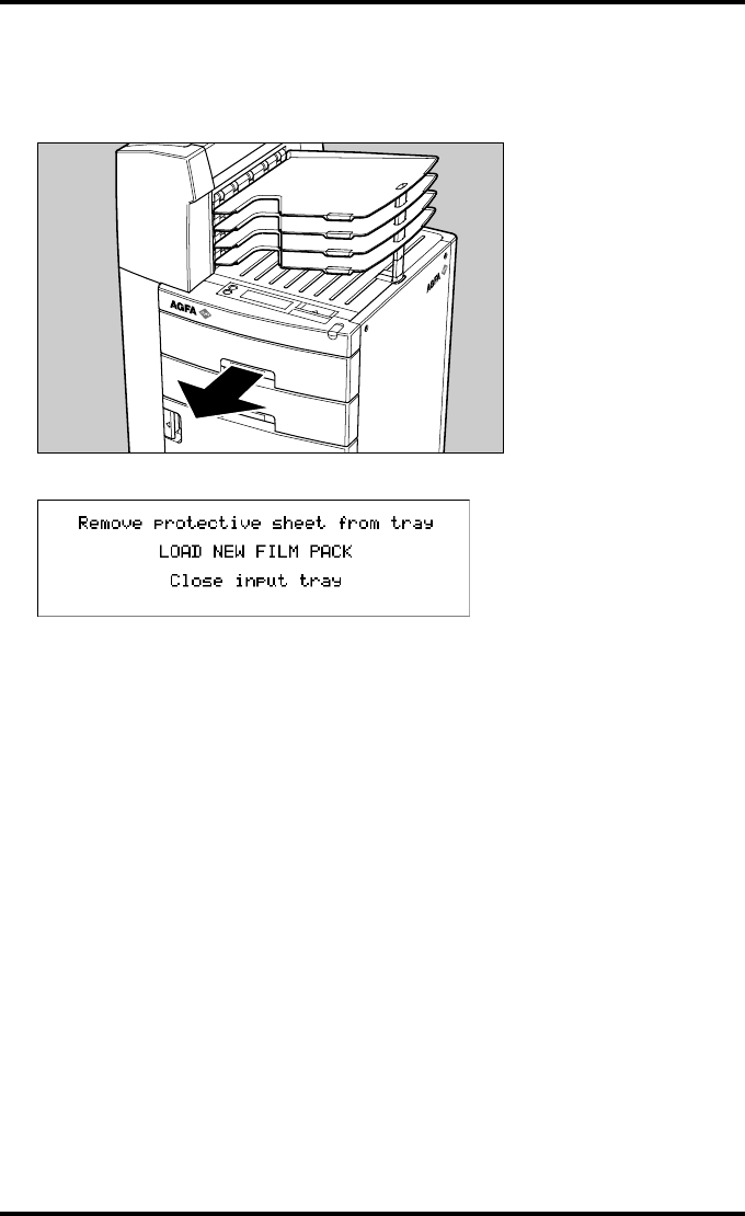
5Open the lower input tray.
6Load a new film pack.
Refer to ‘Film loading procedure’ on page 50.
You have 5 seconds to open the input tray. If you do not open the tray within that
time, the first screen (step 1 or 5 respectively) is presented again, or printing is
resumed when a job is received for which media is available.
49
2900H EN 20071108 Basic operation (operator mode)
DRYSTAR 5500/5503 REFERENCE MANUAL
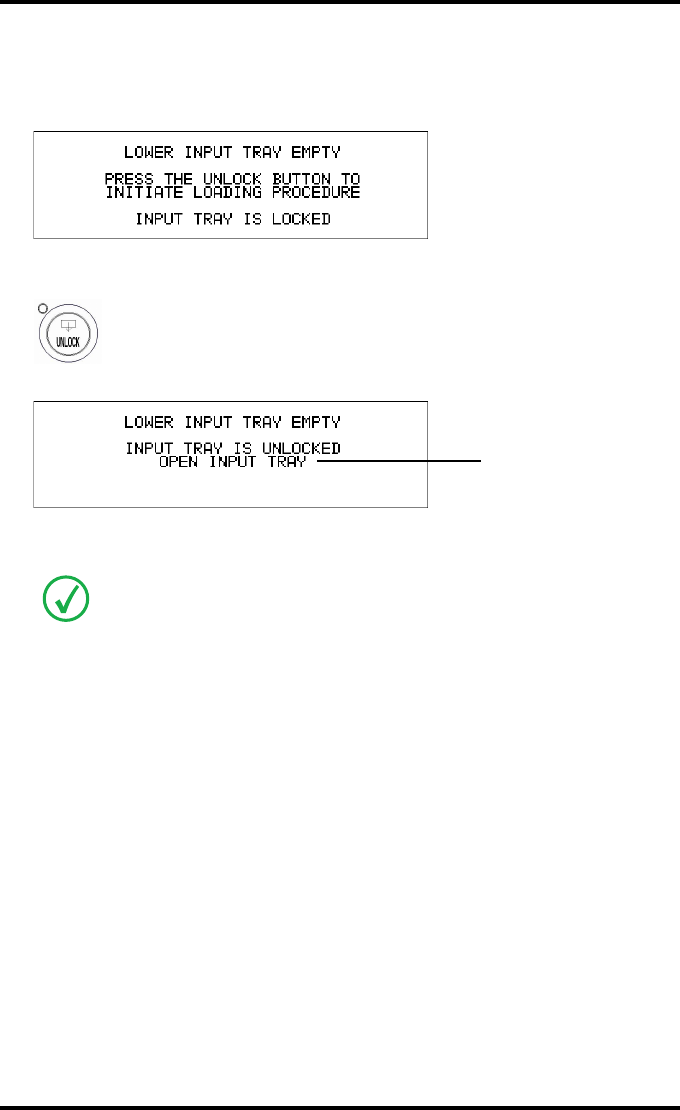
When the Drystar 5500 is in the ready state:
1The display shows the following message:
2Press the Unlock button to initiate the loading sequence.
The printer is ready to receive a new film pack when the following message appears:
3Open the lower input tray.
4Load a new film pack.
Refer to ‘Film loading procedure’ on page 50.
You have 5 seconds to open the input tray. If you do not open the tray within that
time, the first screen (step 1 or 5 respectively) is presented again, or printing is
resumed when a job is received for which media is available.
Blinking
50 2900H EN 20071108Basic operation (operator mode)
DRYSTAR 5500/5503 REFERENCE MANUAL
Film loading procedure
1Open the empty input tray.
The display shows the following message:
2Remove the white cover sheet.
51
2900H EN 20071108 Basic operation (operator mode)
DRYSTAR 5500/5503 REFERENCE MANUAL
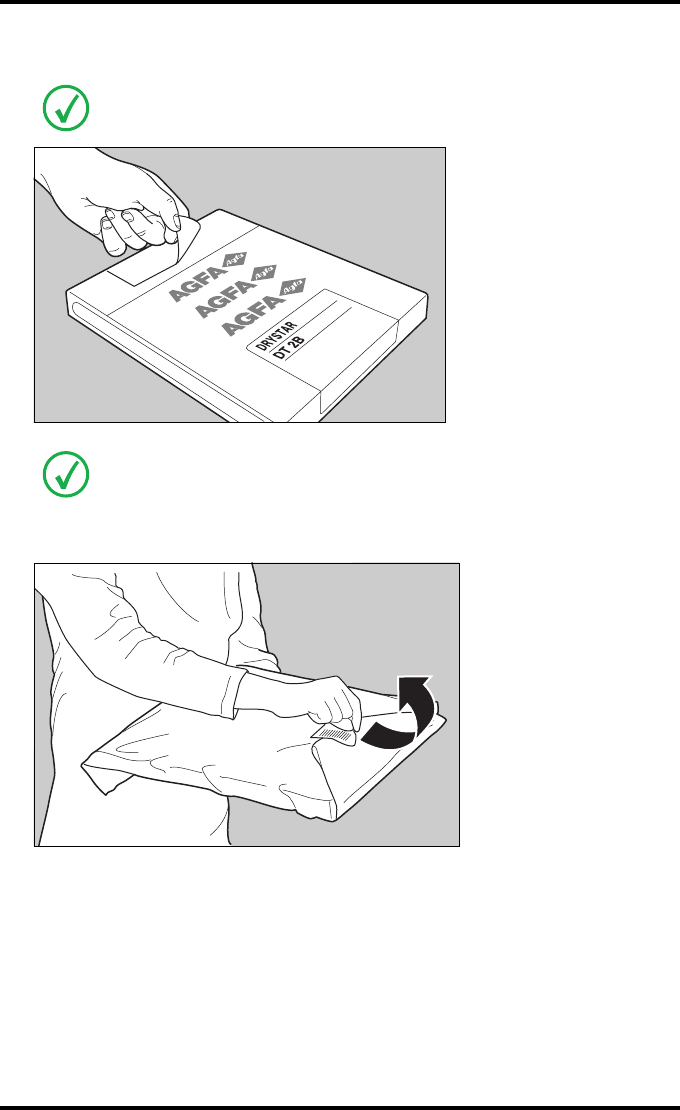
3Take film pack, and open it.
4Remove the sticker from the film pack.
Verify that the film type on the film pack corresponds with the sticker on the tray! If
you do use an other film type, you are advised to change the label on the tray.
You can put the film pack onto a table to make manipulation easier. Before you do
this, make sure that the table is dust-free!
52 2900H EN 20071108Basic operation (operator mode)
DRYSTAR 5500/5503 REFERENCE MANUAL
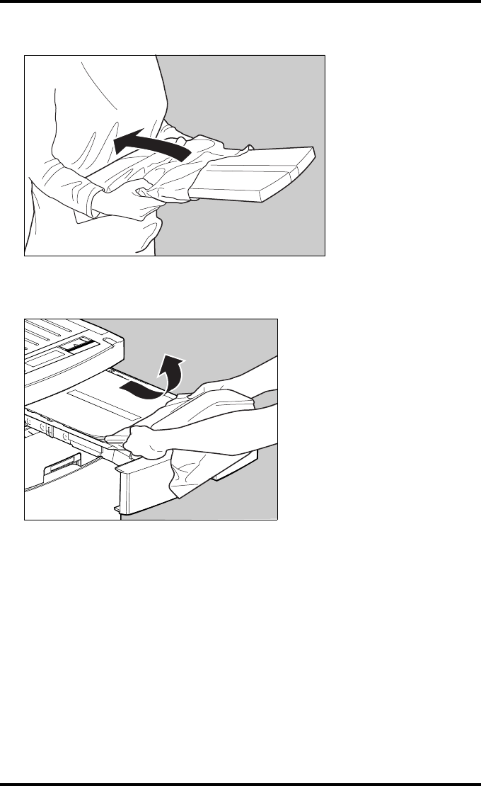
5Remove the plastic film bag partially.
6Slide the film pack into the input tray, and remove the plastic film bag
completely.
53
2900H EN 20071108 Basic operation (operator mode)
DRYSTAR 5500/5503 REFERENCE MANUAL
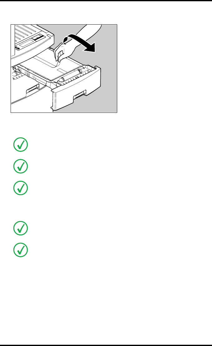
7Tear and remove the plastic tape from around the film pack.
8Close the input tray.
The Drystar 5500 resumes printing as soon as the tray is closed.
Loading instructions are also available on the input tray cover.
Never load another film format when the input tray is not empty. Intermediate
changing of film formats increases the risk for dust, which can damage the thermal
print head (TPH).
The system performs an automatic calibration when the film format has been
changed.
Never reuse a jammed film. Refer to ‘Clearing of film jams’ on page 199.
Only the Drystar 5503 is equipped with a “back side printing” detection
mechanism.. This mechanism is acvtivated only when the software 6.x is installed
and a wrongly inserted film sheet in the input tray is used for printing. In this case
the user receives a warning. The Drystar 5500 does not have this feature.
54 2900H EN 20071108Basic operation (operator mode)
DRYSTAR 5500/5503 REFERENCE MANUAL
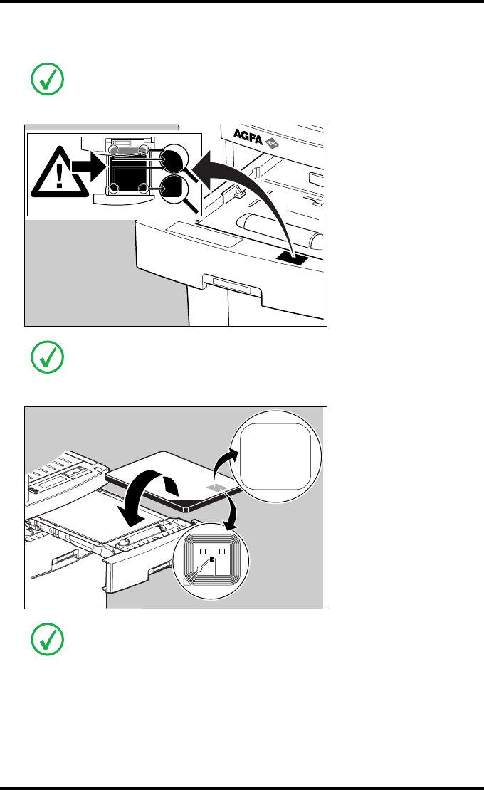
Checking the correct position of a film in the input tray
You can verify that the film is properly loaded by watching the lower right corner of
the films in the input tray. The rounding of this corner should be smaller than the
other three corners. This is also indicated on the sticker at the right side of the input
tray cover.
When closing the input tray, the Film Identification tag is read and the printer
settings are automatically adjusted. The Film Identification tag is located on the
protective sheet on the backside of the film pack. The figure below shows the film
pack upside down.
For some new film types, the Film Identification tag will be covered by a sticker and
therefore will not be visible.

Advanced operation
(Key-operator mode)
This chapter gives an overview of functions for the advanced
user:
TOverview of Key-operator functions
TStopping the printing process
TViewing printer information
TChanging the configuration settings
TPrinting images
TSaving the configuration settings
TRestoring the configuration settings
TPerforming the calibration procedures
TInstallation
TQuality control for general radiography applications
(DT 2 B & DT 2 C)
TQuality control for mammography application
(DT 2 Mammo) (optional)
Chapter 3
56 2900H EN 20071108Advanced operation (Key-operator mode)
DRYSTAR 5500/5503 REFERENCE MANUAL
Overview of Key-operator functions
The Key-operator menus make it possible to use the Drystar 5500 advanced
functions. If not specified otherwise, the functions are described in detail in
this chapter.
For general information on the functions of the Drystar 5500 keys, refer to
‘The local user interface’ on page 27.
Overview
The Drystar 5500 features the following functions on the main menu level of
the Key-operator mode:
Refer to the indicated page for an explanation of the function and the
appropriate procedures.
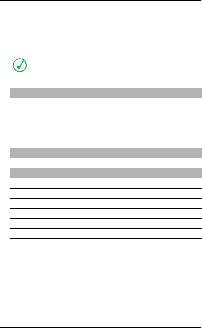
Menu item Function Page
Stop printing To halt the printing procedure 59
Show settings To consult the current settings of the printer. 60
Change settings To change the current settings of the printer. 69
Print Image
To print one of the standard Drystar 5500 test
images. To load and print images from a floppy
disk.
100
Save configuration To make a back-up of the printer settings. 105
Restore
configuration To restore the back-up of the printer settings. 107
Calibration To calibrate the printer. 111
Installation To install the software with the installation
wizard. 121
Quality control
To control with a daily procedure the image
quality respectively of general radiography &
mammography (optional) applications.
141
&
153
57
2900H EN 20071108 Advanced operation (Key-operator mode)
DRYSTAR 5500/5503 REFERENCE MANUAL
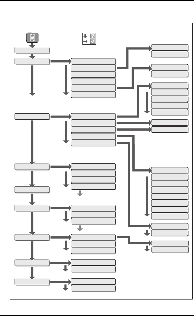
The menu structure
General
Upper input tray
Lower input tray
Network Dicom
Image quality
General
Input tray
Network Dicom
Image quality
Sorter configuration
Test image
From printer floppy
image 1.tif
image 2.tif
General
Sorter configuration
Called AE-title
Hostname
Domain name
Printer IP-address
Netmask
Router IP-address
Remove modality
Add modality
General
Per modality
From floppy (recommended)
Settings 10/09/04 10:55
Film
Printhead profile Upper input tray
Install data-sets
Settings 08/12/04 08:05
TPH cleaning
Assignment modal./tray
Beep on empty tray
Date and time
Language
Film view
Per modality
Installation
Printer Installation wizard
Upper input tray
Quality control
Lower input tray
Calibration
Restore configuration
Save configuration
Change settings
Film view
Lower input tray
Upper input tray
Lower input tray
=
=
Show settings
Stop printing
Print image
Logical printers
58 2900H EN 20071108Advanced operation (Key-operator mode)
DRYSTAR 5500/5503 REFERENCE MANUAL
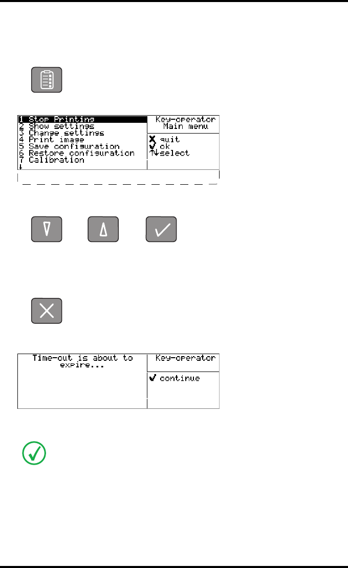
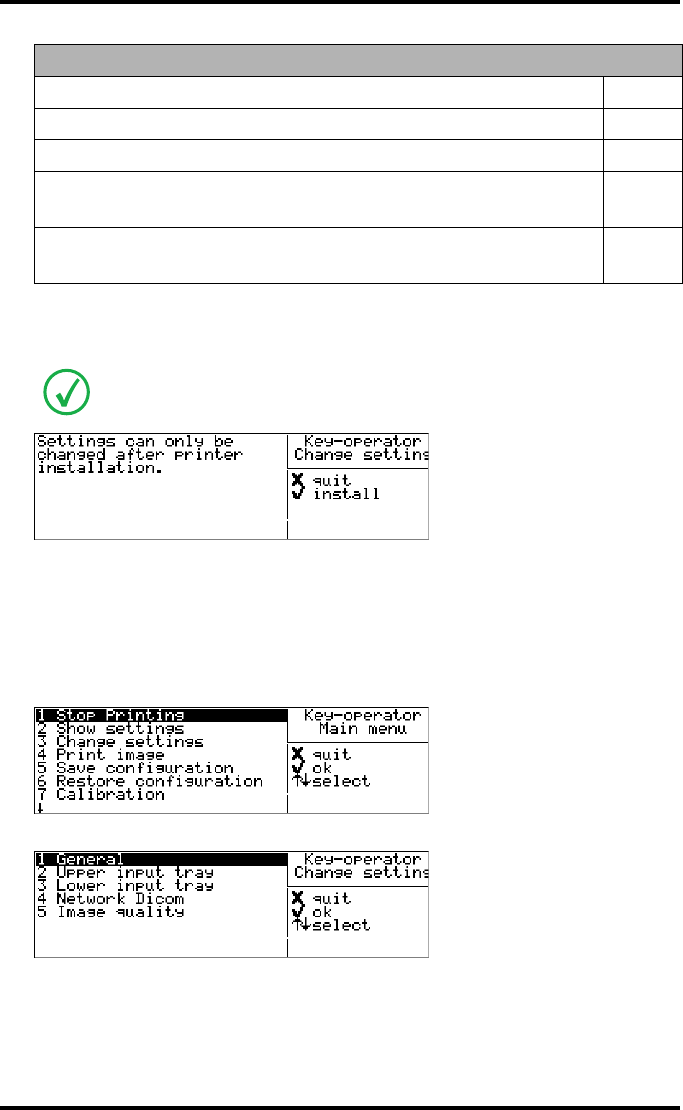
Accessing the Key-operator menus
•The Key-operator mode functions (i.e. the main menu level) can be
accessed by pressing the Key-operator key on the front panel.
After pressing the Key-operator key the Main menu is displayed:
•You can scroll through the menu items by pressing the Down and Up keys
and select a menu item by pressing the Confirm key.
•At any moment, you can press the Escape key on the main menu level to
exit the Key-operator mode. If you press this key on a lower level menu you
are returned to the higher level menu. If you press this key on a data screen
after entering information, all changes on that screen are lost.
•A time-out function (default set to ten minutes) is foreseen. When this
time-out is about to expire, the following screen is displayed:
Press the Confirm key to return to the Key-operator menu. Otherwise, the Key-
operator menu will be closed.
The Drystar 5500 will sound a long beep if you press a key that is not to be used at
that moment.
7 Installation
8 Quality control
59
2900H EN 20071108 Advanced operation (Key-operator mode)
DRYSTAR 5500/5503 REFERENCE MANUAL
Stopping the printing process
To stop the printing process on an adequate way, it is recommended to use the
Stop printing menu.
Accessing the Stop printing menu
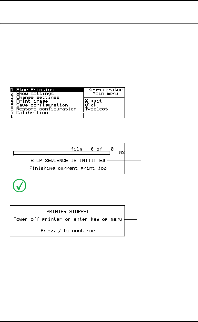
1Press the Key-operator key to enter the Key-operator mode.
2On the Key-operator main menu, press the Confirm key to select ‘Stop printing’.
While the current print job is finished, the Stop Printing screen is displayed:
After the current print job is completed, the following screen is displayed:
3Press the Confirm key to resume printing or press the Escape key to return to
the Key-operator main menu.
The modality name defined during installation will be used to refer to the
corresponding modality. In case there is also a nickname (daily used name) defined
during installation, the nickname is used.
<Modality name>> 10:21:34 PRINTING
1 2
Blinking
Blinking
60 2900H EN 20071108Advanced operation (Key-operator mode)
DRYSTAR 5500/5503 REFERENCE MANUAL
Viewing printer information
A number of data and parameter settings of the printer can be viewed by using
the ‘Show settings’ function:
Show settings Page
General
‘Viewing general information’ 62
Input tray
‘Viewing input tray information’ 62
Network (DICOM)
‘Viewing network (DICOM) information’ 64
Sorter configuration
‘Viewing the sorter configuration’ 65
Image quality
‘Viewing general Image quality information’ 66
‘Viewing Image quality information for a modality’ 67
Logical printers
‘Viewing the logical printers configuration’ 68
61
2900H EN 20071108 Advanced operation (Key-operator mode)
DRYSTAR 5500/5503 REFERENCE MANUAL
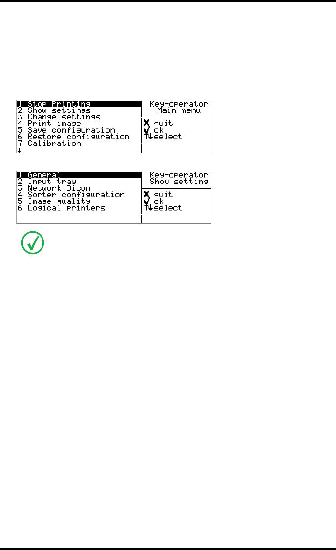
Accessing the Show settings menu
1Press the Key-operator key to enter the Key-operator mode.
2On the Key-operator main menu, press the Down key once, followed by the
Confirm key to select ‘Show settings’.
The Show settings menu is displayed:
3Press the Escape key to return to the Key-operator main menu.
4Press the Escape key to quit the Key-operator mode.
This menu is the starting point for viewing printer information.
62 2900H EN 20071108Advanced operation (Key-operator mode)
DRYSTAR 5500/5503 REFERENCE MANUAL
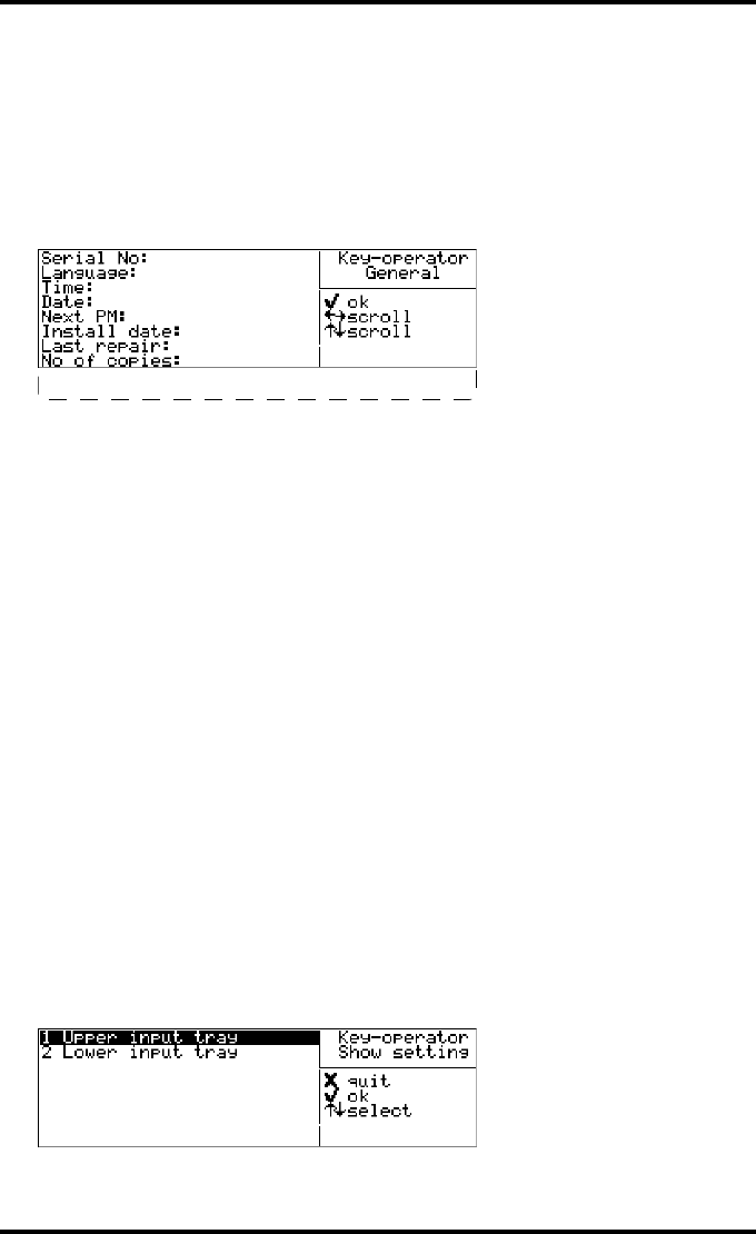
Viewing general information
1Perform steps 1 and 2 of the ‘Accessing the Show settings menu’ procedure, on
page 61.
2On the Show settings menu, press the Confirm key to select ‘General’.
The ‘General’ info screen is displayed:
Use the Up and Down keys to scroll through the following items:
•the serial number of the printer,
•the language,
•the current time and date,
•the next preventive maintenance (PM) date,
•the install date,
•the last repair date,
•the total number of films printed,
•the currently installed software version,
•the beep on empty tray setting (No beep, 5 times, many).
3Press the Escape key to return to the Show settings menu.
Viewing input tray information
1Perform steps 1 and 2 of the ‘Accessing the Show settings menu’ procedure, on
page 61.
2On the Show settings menu, press the Down key once, followed by the Confirm
key to select ‘Input tray’.
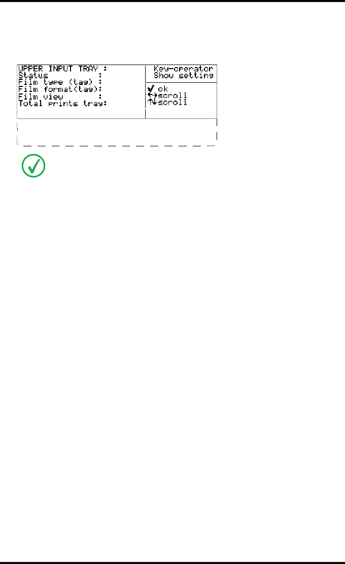
The ‘Input tray’ screen is displayed:
1024
English
12.30
12 Sep 2005
17 Mar 2006
17 Mar 2005
20 Jun 2005
21330
SW-release: R4.0.0 B2
Beep on empty tray:5
63
2900H EN 20071108 Advanced operation (Key-operator mode)
DRYSTAR 5500/5503 REFERENCE MANUAL
3Press the Up and Down keys followed by the Confirm key to select the desired
input tray.
In case you have selected Upper input tray, the Upper input tray screen is displayed:
For both input trays, the following information is displayed on the currently loaded
film:
•the status (OK / disabled/overruled),
•the film type read from the Film Identification tag,
•the film format read from Film Identification tag,
•the film view,
•the total number of prints for the input tray,
•the number of prints for this film pack,
•the brand (ABC Code),
•the order number,
•the pack number.
4Press the Confirm key to return to the Show settings menu.
If you have selected lower input tray, a screen with similar information about the
lower tray is shown.
OK
DT 2 B
14X17"
Normal
11673
Prints current pack:6
EKL38
202458269
83
64 2900H EN 20071108Advanced operation (Key-operator mode)
DRYSTAR 5500/5503 REFERENCE MANUAL
Viewing network (DICOM) information
1Perform steps 1 and 2 of the ‘Accessing the Show settings menu’ procedure, on
page 61.
2On the Show settings menu, press the Down key twice, followed by the Confirm
key to select ‘Network (DICOM)’.
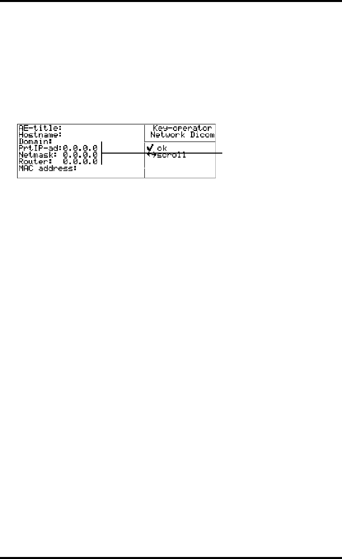
The ‘Network (DICOM)’ screen is displayed:
The following network (DICOM) parameters are displayed:
•AE-title,
•Host name,
•Domain,
•Printer IP-address,
•Netmask,
•Router,
•MAC address.
3Press the Confirm key to return to the Show settings menu.
DS5500
ds5500
xxxxxx
08:00:66:80:
e.g.
Prt IP-ad:123.123.123.123
Netmask:255.255.255.255
Router:123.123.123.123
65
2900H EN 20071108 Advanced operation (Key-operator mode)
DRYSTAR 5500/5503 REFERENCE MANUAL
Viewing the sorter configuration
1Perform steps 1 and 2 of the ‘Accessing the Show settings menu’ procedure, on
page 61.
2On the Show settings menu, press the Down key three times, followed by the
Confirm key to select ‘Sorter Configuration’.
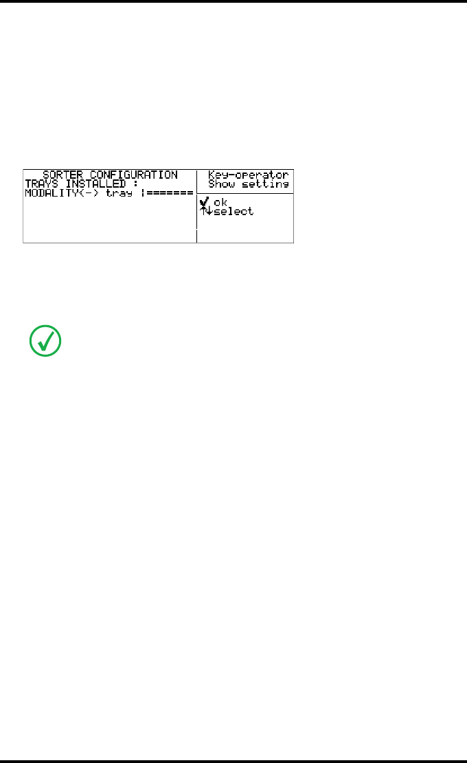
The ‘Sorter Configuration’ screen is displayed:
This screen gives an overview of:
•the installed trays and their positions (the upper tray has position one, the
lower tray position 4).
•the assignment of the installed modalities and corresponding tray(s).
3Press the Up and Down keys to select the modality of your choice.
4Press the Confirm key to return to the Show settings menu.
The previous screen is an example of a situation where only tray 1, 3 and 4 are
installed and the second modality is a fast modality.
1 2 3 4
1 <Modality name> 1
2 <Modality name> 3 4
3 <Modality name> 4
66 2900H EN 20071108Advanced operation (Key-operator mode)
DRYSTAR 5500/5503 REFERENCE MANUAL
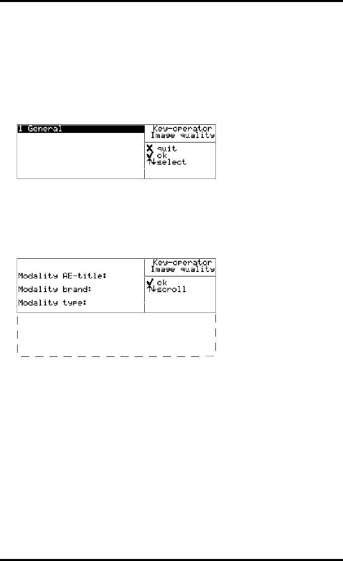
Viewing general Image quality information
1Perform steps 1 and 2 of the ‘Accessing the Show settings menu’ procedure, on
page 61.
2On the Show settings menu, press the Down key four times, followed by the
Confirm key to select ‘Image quality’.
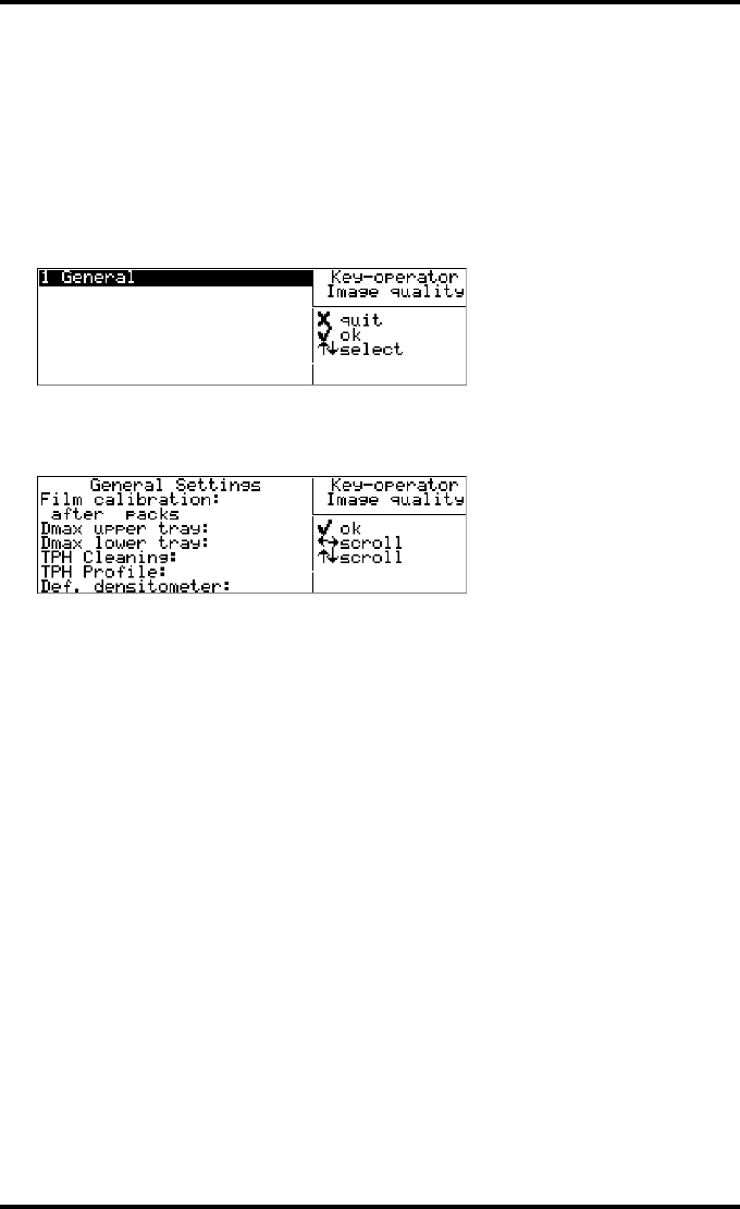
The following screen will appear:
3Press the Confirm key to select ‘General’.
The general Image quality settings are displayed:
The following info is displayed:
•Film calibration setting: OFF/ON with the number of film packs
determining the calibration interval (if ON).
•Dmax upper tray: the maximum density for the upper input tray resulting
from the automatic film calibration.
•Dmax lower tray: the maximum density for the lower input tray resulting
from the automatic film calibration.
•TPH cleaning: the number of prints after the last thermal head cleaning,
and the number of prints to go before a new cleaning session is necessary.
•TPH profile: the number of prints after the last thermal head profile
calibration and the number of prints to go before a new thermal head
profile calibration is necessary.
•Def. densitometer: shows the default densitometer that is used for the
calibrations.
4Press the Confirm key to return to the Image quality menu.
5In the Image quality menu, press the Escape key to return to the Show settings
menu.
2 <Modality name>
3 <Modality name>
4 <Modality name>
5 <Modality name>
6 <Modality name>
7 <Modality name>
OFF
3.12
3.11
OFF
OFF
Macbet
67
2900H EN 20071108 Advanced operation (Key-operator mode)
DRYSTAR 5500/5503 REFERENCE MANUAL
Viewing Image quality information for a modality
1Perform steps 1 and 2 of the ‘Accessing the Show settings menu’ procedure, on
page 61.
2On the Show settings menu, press the Down key four times, followed by the
Confirm key to select ‘Image quality’.
The following screen will appear:
3Press the Up/Down arrow keys, followed by the Confirm key to select the
desired modality.
4Press the Confirm key to display the Image quality settings for the selected
modality, or the Escape key to quit.
5Press the Confirm key to return to the Image quality menu.
6In the Image quality menu, press the Escape key to return to the Show settings
menu.
2 <Modality name>
3 <Modality name>
4 <Modality name>
5 <Modality name>
6 <Modality name>
7 <Modality name>
<Modality name>
DS5500_1
Philips
MXVIEW
Look-up table:
Linear
Interpolation:
Cubic HighRes
Maximum density:
3.00
68 2900H EN 20071108Advanced operation (Key-operator mode)
DRYSTAR 5500/5503 REFERENCE MANUAL
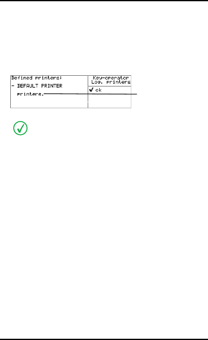
Viewing the logical printers configuration
1Perform steps 1 and 2 of the ‘Accessing the Show settings menu’ procedure, on
page 61.
2On the Show settings menu, press the Down key five times, followed by the
Confirm key to select ‘Logical printers’.
The ‘Logical printers’ screen is displayed:
This screen gives an overview of the logical printers defined in the Drystar 5500.
3Press the Confirm key to return to the Show settings menu.
The Logical printers information can be helpful when assigning a modality output
to a particular Drystar 5500 profile. Configuring logical printers can only be done
via a connected remote pc. Contact your local service organization for more
information.
1 other logical printer
e.g. DS_5500_2
69
2900H EN 20071108 Advanced operation (Key-operator mode)
DRYSTAR 5500/5503 REFERENCE MANUAL
Changing the configuration settings
A number of data and parameters settings of the printer can be viewed and
changed by using the ‘change settings’ function.
Each time the settings have been changed, the new configuration is automatically
stored on the hard disk of the printer. You will be asked to create a back-up floppy
with the new settings.
Change settings Page
General
‘Changing the date and time’ 72
‘Changing the language’ 73
‘Changing the sorter configuration’ 74
‘Changing the assignment modality - output tray’ 75
‘Changing the beep on empty tray settings’ 76
Input tray (Upper or Lower)
‘Changing the film view’ 77
Network (DICOM)
‘Changing the Printer AE-title (Called AE-title)’ 78
‘Changing the Hostname’ 79
‘Changing the Domain name’ 80
‘Changing the Printer IP-address’ 81
‘Changing the Netmask’ 83
‘Changing the Router IP-address’ 84
‘Removing a modality’ 86
‘Adding a modality’ 87
70 2900H EN 20071108Advanced operation (Key-operator mode)
DRYSTAR 5500/5503 REFERENCE MANUAL
Accessing the Change settings menu
Proceed as follows to access the ‘Change settings’ menu:
1Press the Key-operator key to enter the Key-operator mode.
2On the Key-operator main menu, press the Down key twice, followed by the
Confirm key to select ‘Change settings’.
The ‘Change settings’ screen is displayed:
3Press the Escape key to return to the Key-operator main menu.
Image quality
‘Changing general image quality settings - Film calibration’ 91
‘Changing general image quality settings - Default densitometer’ 93
‘Changing Image quality setting for a modality - Selecting a lookup table’ 94
‘Changing Image quality setting for a modality - Changing the
Interpolation’ 96
‘Changing Image quality setting for a modality - Changing the maximum
density (Dmax)’ 98
If the printer has not yet been installed, the ‘printer installation wizard’ should be
executed first. In this case, the following screen is displayed:
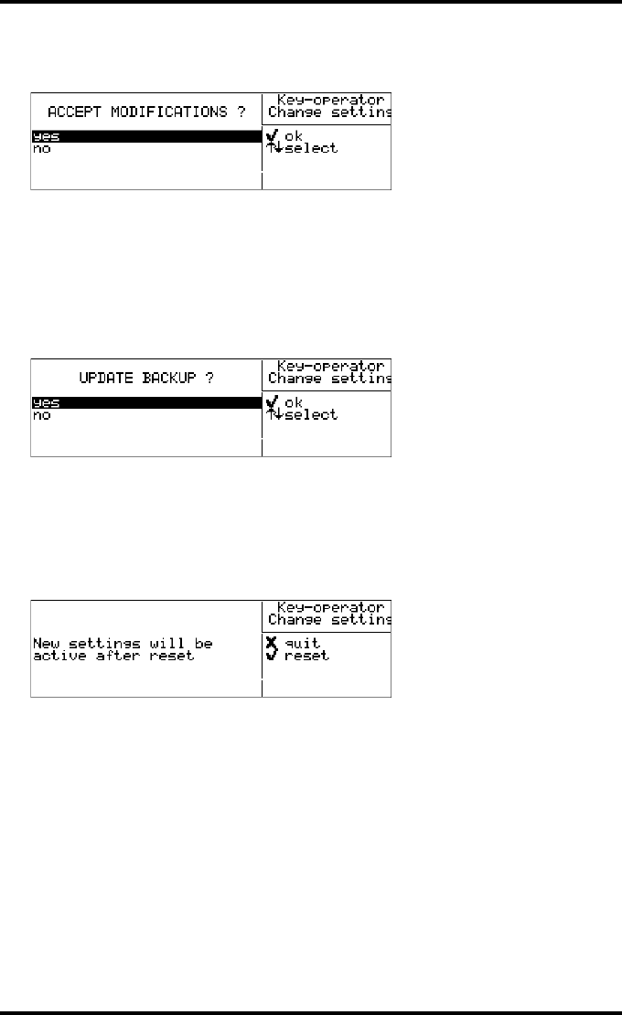
71
2900H EN 20071108 Advanced operation (Key-operator mode)
DRYSTAR 5500/5503 REFERENCE MANUAL
4Press the Escape key to quit the Key-operator mode.
When the settings have been changed, the ‘accept modifications’ window is displayed:
Each time the settings have been changed and confirmed, an automatic back-up of the
new configuration is made on the hard disk. You will also be asked to create a back-up
floppy.
Select ‘yes’ if you wish to accept the changed settings. Press the Confirm key.
Select ‘no’ if you do not wish to accept the changed settings. Press the Confirm key.
You will return to the Main menu.
After selecting ’yes’, the ‘Update back-up’ screen is displayed:
If you want to save the configuration on the back-up floppy, select ‘yes’ and press the
Confirm key. The printer will now enter the ‘Saving the current configuration’ (refer to
page 105).
If you only want to save the configuration on the printer hard disk, select ‘no’ and
press the Confirm key.
Next, the following screen is displayed:
Press the Confirm key to reset. After the reset, the new settings will be active.
Press the Escape key to quit the application. The old settings will remain active until
the next reset.
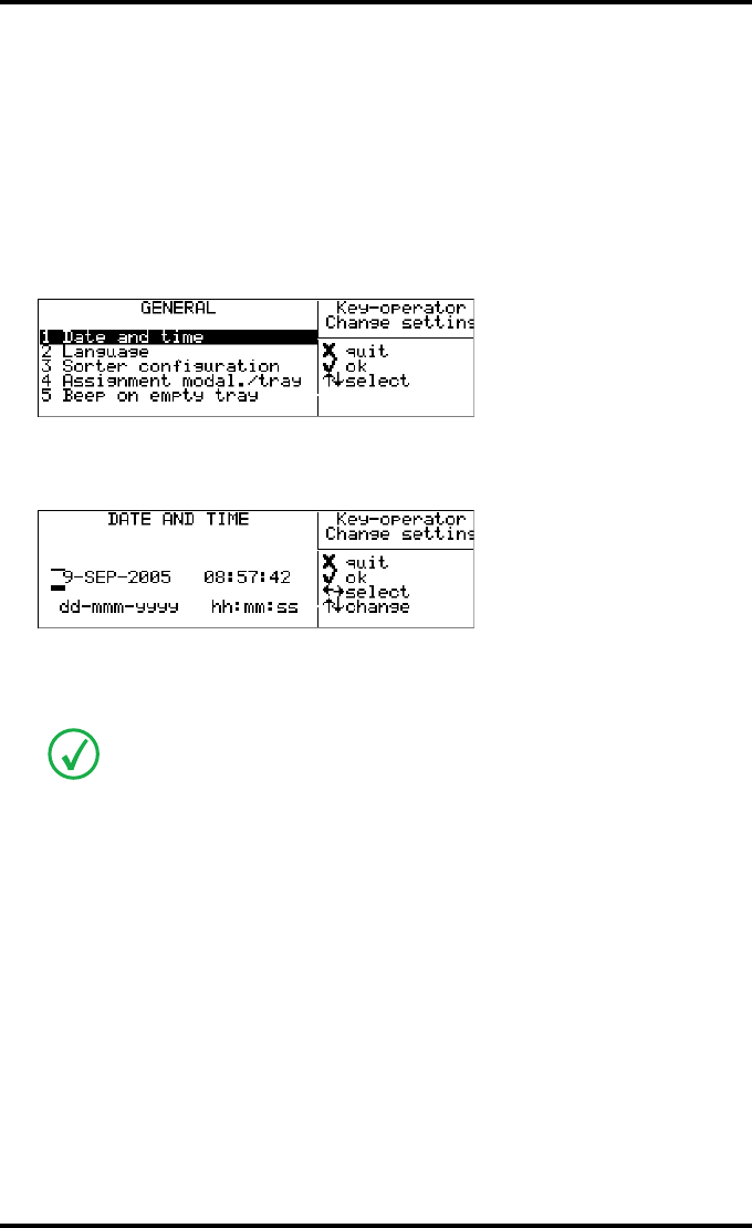
72 2900H EN 20071108Advanced operation (Key-operator mode)
DRYSTAR 5500/5503 REFERENCE MANUAL
Changing the General settings
Changing the date and time
1Perform steps 1 to 2 of the ‘Accessing the Change settings menu’ procedure on
page 70.
2On the ‘Change setting’ screen, press the Confirm key to select ‘General’.
The ‘General’ screen is displayed:
3Press the Confirm key to select ‘Date and time’.
The ‘Date and time’ screen is displayed:
4Press the Up/Down arrow keys to increment/decrement the numbers. Press the
Left/Right arrow keys to move through the digits.
5Press the Confirm key to store the data, or the Escape key to quit the procedure
without any changes.
For more info, refer to ‘Data entry’ on page 33.
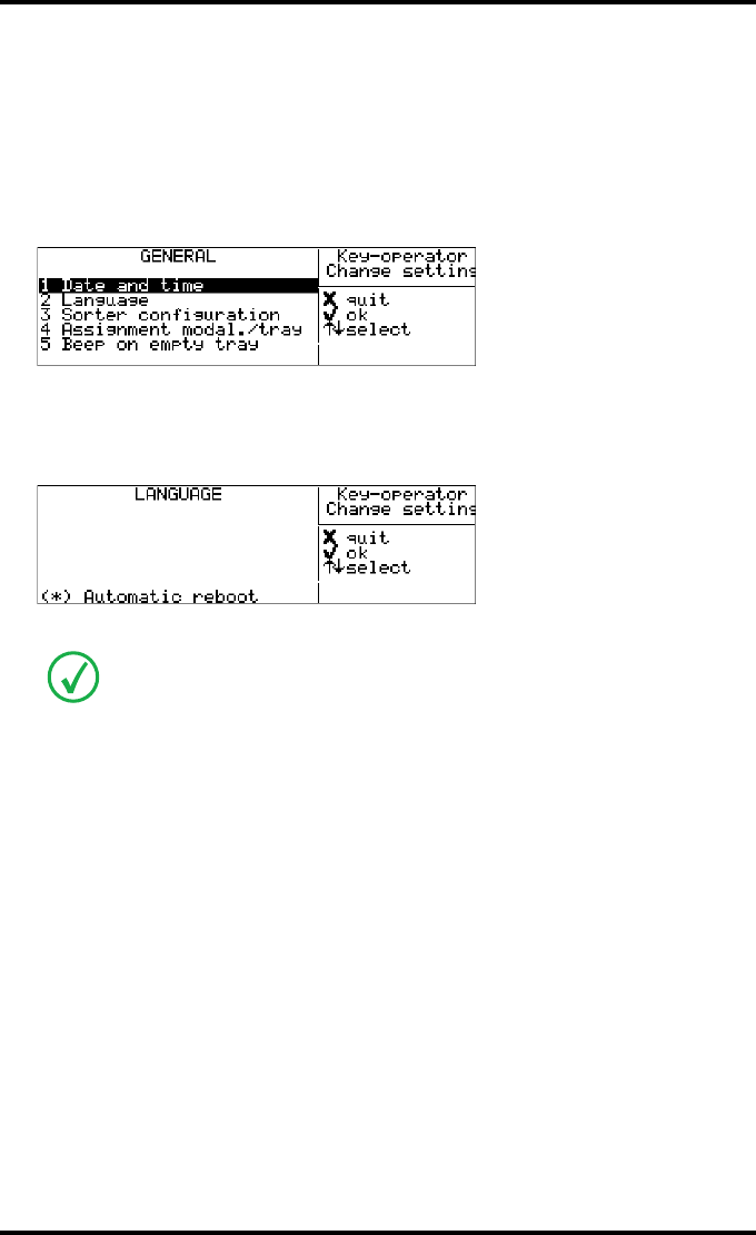
73
2900H EN 20071108 Advanced operation (Key-operator mode)
DRYSTAR 5500/5503 REFERENCE MANUAL
Changing the language
1Perform steps 1 to 2 of the ‘Accessing the Change settings menu’ procedure on
page 70 to select the ‘General’ screen.
2On the ‘Change setting’ screen, press the Confirm key to select ‘General’.
The ‘General’ screen is displayed:
3On the ‘General’ screen, press the Down key once, followed by the Confirm key
to select ‘Language’.
The ‘Language’ screen is displayed with the available languages. For example:
The current language is marked with an asterisk (*).
4Press the Up/Down arrow keys, followed by the Confirm key to select the
desired language.
5Press the Confirm key to store the data, or the Escape key to quit the procedure
without any changes.
The number of displayed languages depends on the installed dataset. Contact your
local Agfa service organization for the latest Drystar 5500 language availability
status.
1*English
2 Nederlands
3 Francais
4 Deutsch
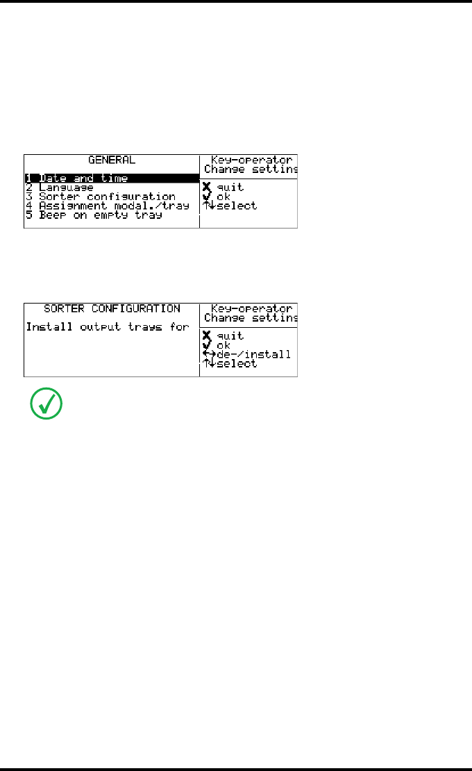
74 2900H EN 20071108Advanced operation (Key-operator mode)
DRYSTAR 5500/5503 REFERENCE MANUAL
Changing the sorter configuration
1Perform steps 1 to 2 of the ‘Accessing the Change settings menu’ procedure on
page 70 to select the ‘General’ screen.
2On the ‘Change setting’ screen, press the Confirm key to select ‘General’.
The ‘General’ screen is displayed:
3On the ‘General’ screen, press the Down key twice, followed by the Confirm key
to select ‘Sorter Configuration’.
The ‘Sorter Configuration’ screen is displayed:
4Use the Up and Down keys to select the output tray you wish to configure and
press the Left/Right arrow keys to install/uninstall the output tray.
5Click OK to install the indicated output tray.
An asterix left from an output tray indicates that the respective output tray is
installed.
*position 1 (upper)
*position 2
position 3
*
p
osition 4
(
lower
)
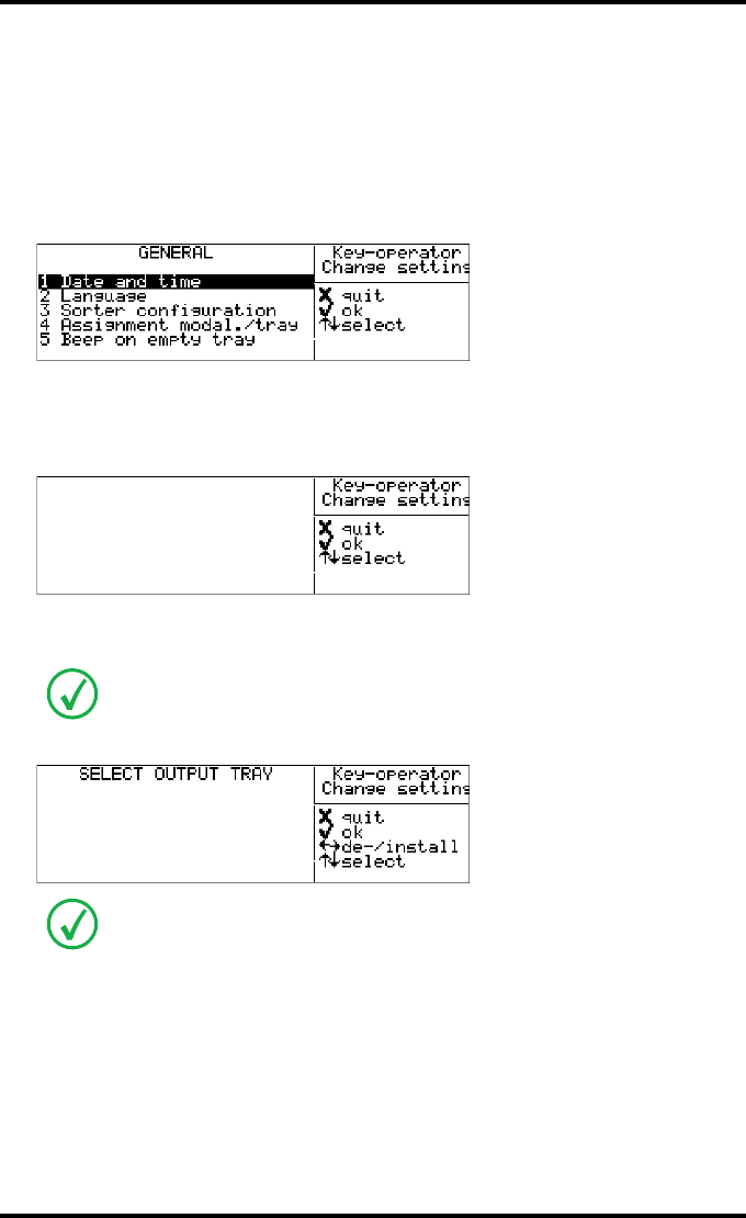
75
2900H EN 20071108 Advanced operation (Key-operator mode)
DRYSTAR 5500/5503 REFERENCE MANUAL
Changing the assignment modality - output tray
1Perform steps 1 to 2 of the ‘Accessing the Change settings menu’ procedure on
page 70 to select the ‘General’ screen.
2On the ‘Change setting’ screen, press the Confirm key to select ‘General’.
The ‘General’ screen is displayed:
3On the ‘General’ screen, press the Down key three times, followed by the
Confirm key to select ‘Assignment modal./tray’.
The ‘Assignment modal./tray’ screen is displayed:
4Select a modality by using the select key and pressing Confirm.
The following window is displayed:
5Use the Up/Down arrow keys to select the output trays for the particular
modality and press the Left/Right arrow keys to install button to uninstall/
install the output tray.
If you have selected more than one input tray, you must consecutively assign the
output trays.
The number of selections depends on the number of modalities defined.
An asterix left from an output tray indicates that the respective output tray is
installed.
1 <Modality name>
2 <Modality name>
3 <Modality name>
4 <Modality name>
5 <Modality name>
6 <Modality name>
7 <Modality name>
<Modality name>
*position 1 (upper)
position 2
position 3
p
osition 4
(
lower
)
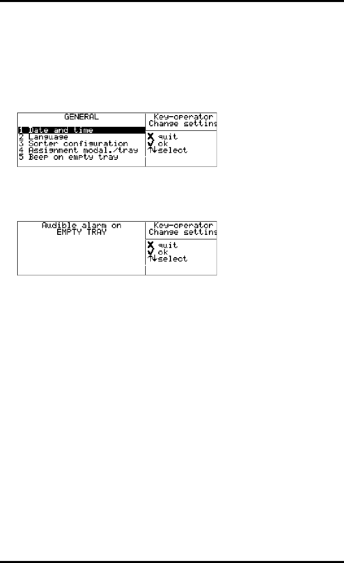
76 2900H EN 20071108Advanced operation (Key-operator mode)
DRYSTAR 5500/5503 REFERENCE MANUAL
Changing the beep on empty tray settings
1Perform steps 1 to 2 of the ‘Accessing the Change settings menu’ procedure on
page 70 to select the ‘General’ screen.
2On the ‘Change setting’ screen, press the Confirm key to select ‘General’.
The ‘General’ screen is displayed:
3On the ‘General’ screen, press the Down key four times, followed by the Confirm
key to select ‘Beep on empty tray’.
The ‘Audible alarm on empty tray’ screen is displayed:
4Use the Up/Down arrow keys to select the desired setting:
•Select ‘No alarm’ if you do not want an audible signal to warn you that a
tray is empty.
•Select 5 times to hear 5 consecutive beeps at the moment a tray gets empty.
•Select ‘While tray is empty’ to hear a beep the whole time a tray is empty.
5Press the Confirm key to store the data, or the Escape key to quit the procedure
without any changes.
No alarm
*5 times
While tray is empty
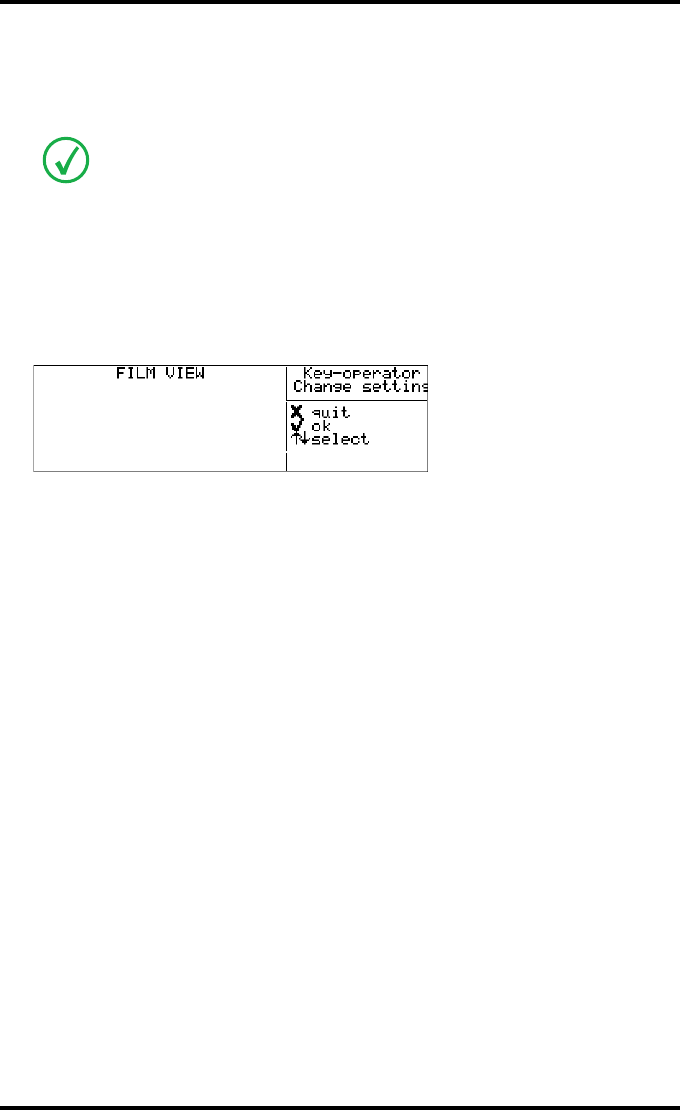
77
2900H EN 20071108 Advanced operation (Key-operator mode)
DRYSTAR 5500/5503 REFERENCE MANUAL
Changing the input tray settings (upper / lower)
Changing the film view
1Perform steps 1 and 2 of the ‘Accessing the Change settings menu’ procedure on
page 70 to select the ‘Upper input tray’ screen.
2In the ‘Upper input tray’ screen, press the Down key twice, followed by the
Confirm key to select ‘Film view’.
The ‘Film view’ screen is displayed:
The current film view is indicated with an *.
3Press the Up/Down arrow keys to select the desired film view.
4Press the Confirm key to store the data, or the Escape key to quit the procedure
without any changes.
In the procedure, we will assume that the film view for the upper input tray is to be
changed. The procedure for the lower input tray is identical.
1* Normal
2Back
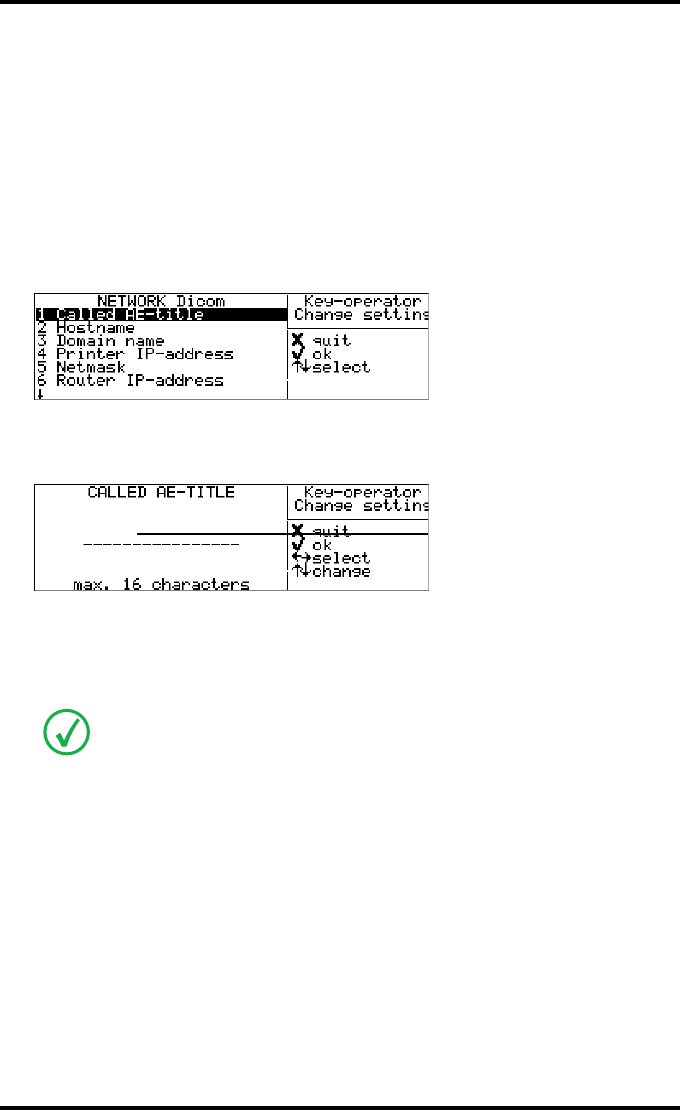
78 2900H EN 20071108Advanced operation (Key-operator mode)
DRYSTAR 5500/5503 REFERENCE MANUAL
Changing Network (DICOM) configuration
Changing the Printer AE-title (Called AE-title)
1Perform steps 1 to 2 of the ‘Accessing the Change settings menu’ procedure on
page 70.
2On the ‘Change setting’ screen, press the Down key three times, followed by the
Confirm key to select ‘Network Dicom’.
The ‘Network Dicom’ screen is displayed:
3Press the Confirm key to select ‘Called AE-title’.
The ‘Called AE-title’ screen is displayed:
If the printer AE-Title has already been assigned, it will be shown on the display.
4Change the printer AE-title by means of the arrow keys. Refer to ‘Data entry’ on
page 33. Make sure not to enter more than 16 characters.
5Press the Confirm key to store the data, or the Escape key to quit the procedure
without any changes.
Entries are case sensitive.
e.g. DS5500e.g. DS5500

79
2900H EN 20071108 Advanced operation (Key-operator mode)
DRYSTAR 5500/5503 REFERENCE MANUAL
Changing the Hostname
1Perform steps 1 to 2 of the ‘Accessing the Change settings menu’ procedure on
page 70.
2On the ‘Change setting’ screen, press the Down key three times, followed by the
Confirm key to select ‘Network Dicom’.
The ‘Network Dicom’ screen is displayed:
3In the ‘Network-Dicom’ screen, press the Down key once, followed by the
Confirm key to select ‘Hostname’.
The ‘Hostname’ screen is displayed:
If the Host name has already been assigned, it will be shown on the display.
4Change the hostname by means of the arrow keys. Refer to ‘Data entry’ on
page 33. Make sure not to enter more than 16 characters.
5Press the Confirm key to store the data, or the Escape key to quit the procedure
without any changes.
Entries are case sensitive.
e.g. ds5500
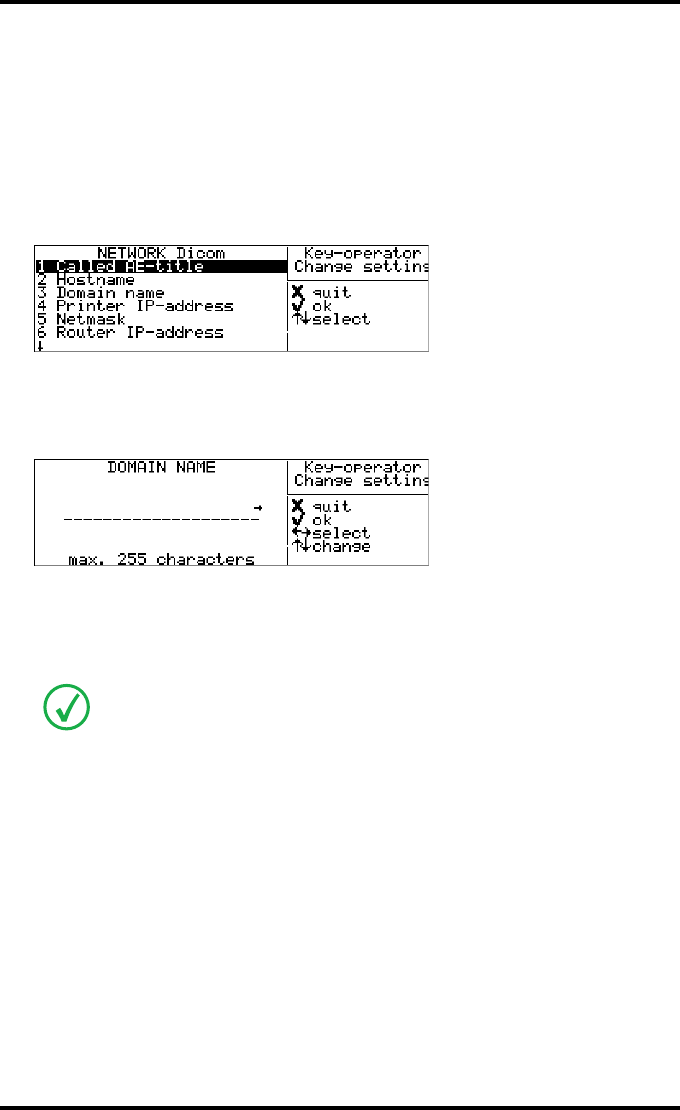
80 2900H EN 20071108Advanced operation (Key-operator mode)
DRYSTAR 5500/5503 REFERENCE MANUAL
Changing the Domain name
1Perform steps 1 to 2 of the ‘Accessing the Change settings menu’ procedure on
page 70.
2On the ‘Change setting’ screen, press the Down key three times, followed by the
Confirm key to select ‘Network Dicom’.
The ‘Network Dicom’ screen is displayed:
3On the ‘Network-Dicom’ screen, press the Down key twice, followed by the
Confirm key to select ‘Domain name’.
The ‘Domain name’ screen is displayed:
If the domain name has already been assigned, it will be shown on the display.
4Enter the domain name by means of the arrow keys. Refer to ‘Data entry’ on
page 33.
5Press the Confirm key to store the data, or the Escape key to quit the procedure
without any changes.
Entries are case sensitive.
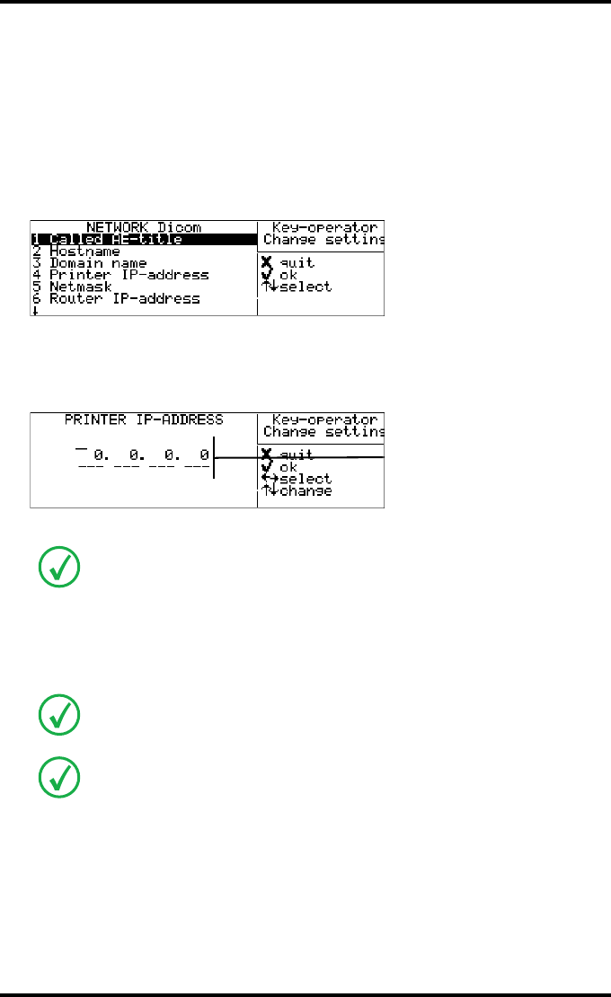
81
2900H EN 20071108 Advanced operation (Key-operator mode)
DRYSTAR 5500/5503 REFERENCE MANUAL
Changing the Printer IP-address
1Perform steps 1 to 2 of the ‘Accessing the Change settings menu’ procedure on
page 70.
2On the ‘Change setting’ screen, press the Down key three times, followed by the
Confirm key to select ‘Network Dicom’.
The ‘Network Dicom’ screen is displayed:
3On the ‘Network-Dicom’ screen, press the Down key three times, followed by
the Confirm key to select ‘Printer IP-address’.
The ‘Printer IP-address’ screen is displayed:
If the IP-address has already been assigned, it will be shown on the display.
4Press the Up/Down arrow keys to increment/decrement the numbers. Press the
Left/Right arrow keys to move through the fields. Press the Confirm key to store
the data.
When no DHCP server is available and when the IP address of the printer has never
been set, the printer IP address will be set to the address 169.254.10.10.
Refer to ‘Data entry’ on page 33.
Note that blank spaces will not be filled in (see examples on the next page).
e.g. 10.233. 93. 46

82 2900H EN 20071108Advanced operation (Key-operator mode)
DRYSTAR 5500/5503 REFERENCE MANUAL
Example: If the IP-address is 120.000.120.120, then the data entry should be as
follows:
Example: If the IP-address is 120.0.120.120, then the data entry should be as follows:
5Press the Confirm key to store the data, or the Escape key to quit the procedure
without any changes.
12 .00 .12 .12
12 . .12 .12

83
2900H EN 20071108 Advanced operation (Key-operator mode)
DRYSTAR 5500/5503 REFERENCE MANUAL
Changing the Netmask
1Perform steps 1 to 2 of the ‘Accessing the Change settings menu’ procedure on
page 70.
2On the ‘Change setting’ screen, press the Down key three times, followed by the
Confirm key to select ‘Network Dicom’.
The ‘Network Dicom’ screen is displayed:
3On the ‘Network-Dicom’ screen, press the Down key four times, followed by the
Confirm key to select ‘Netmask’.
The ‘Netmask’ screen is displayed:
If the Netmask has already been assigned, it will be shown on the display.
4Enter the Netmask by means of the arrow keys. Refer to ‘Data entry’ on page 33.
When no DHCP server is available and when the subnet mask of the printer has
never been set, the subnet mask will be set to the APIPA address 255.255.0.0.
Note that blank spaces will not be filled in (see examples on the next page).
e.g. 255.255.252. 0
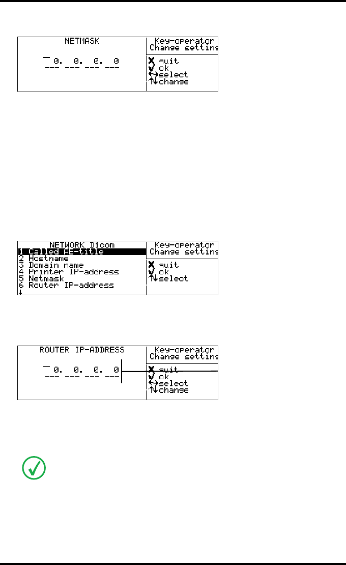
84 2900H EN 20071108Advanced operation (Key-operator mode)
DRYSTAR 5500/5503 REFERENCE MANUAL
Example: If the Netmask is 250.760.560. 0, then the data entry should be as follows:
5Press the Confirm key to store the data, or the Escape key to quit the procedure
without any changes.
Changing the Router IP-address
1Perform steps 1 to 2 of the ‘Accessing the Change settings menu’ procedure on
page 70.
2On the ‘Change setting’ screen, press the Down key three times, followed by the
Confirm key to select ‘Network Dicom’.
The ‘Network Dicom’ screen is displayed:
3On the ‘Network-Dicom’ screen, press the Down key five times, followed by the
Confirm key to select ‘Router IP-address’.
The ‘Router IP-address’ screen is displayed:
If the Router IP-address has already been assigned, it will be shown on the display.
4Enter the Router IP-address by means of the arrow keys. Refer to ‘Data entry’ on
page 33.
Note that blank spaces will not be filled in (see examples on the next page).
25 .76 . 56 .
e.g. 10.233. 92. 1
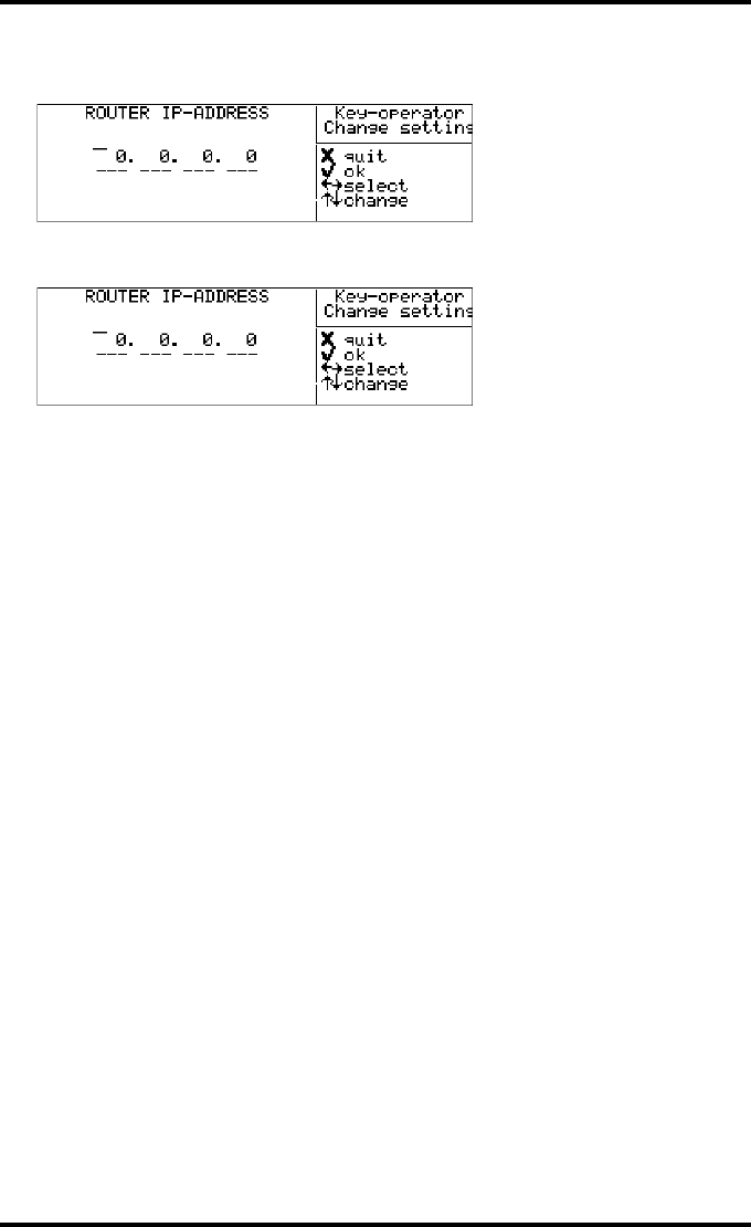
85
2900H EN 20071108 Advanced operation (Key-operator mode)
DRYSTAR 5500/5503 REFERENCE MANUAL
Example: If the Router IP-address is 450.000.210.120, then the data entry should be
as follows:
Example: If the Router IP-address is 450.0.210.120, then the data entry should be as
follows:
5Press the Confirm key to store the data, or the Escape key to quit the procedure
without any changes.
45 . 00 .21 .12
45 . . 21 .12
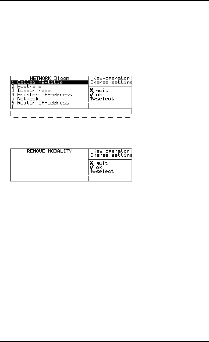
86 2900H EN 20071108Advanced operation (Key-operator mode)
DRYSTAR 5500/5503 REFERENCE MANUAL
Removing a modality
1Perform steps 1 to 2 of the ‘Accessing the Change settings menu’ procedure on
page 70.
2On the ‘Change setting’ screen, press the Down key three times, followed by the
Confirm key to select ‘Network Dicom’.
The ‘Network Dicom’ screen is displayed:
3On the ‘Network-Dicom’ screen, press the Down key six times, followed by the
Confirm key to select ‘Remove modality’.
The ‘Remove modality’ screen is displayed:
The modality names, entered during installation of the printer, are shown in the list. If
no names have been entered, the Called AE-titles are shown instead. In case there is
also a nickname (daily used name) defined during installation, the nickname is used.
4Select the modality which you wish to remove by means of the arrow keys.
5Press the Confirm key to remove the modality name from the list, or the Escape
key to quit the procedure without any changes.
7 Remove modality
8 Add modality
1 <Modality name>
2 <Modality name>
3 <Modality name>
4 <Modality name>
5 <Modality name>
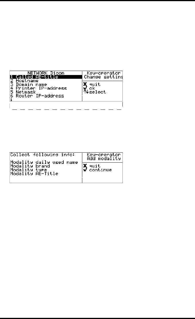
87
2900H EN 20071108 Advanced operation (Key-operator mode)
DRYSTAR 5500/5503 REFERENCE MANUAL
Adding a modality
1Perform steps 1 to 2 of the ‘Accessing the Change settings menu’ procedure on
page 70.
2On the ‘Change setting’ screen, press the Down key three times, followed by the
Confirm key to select ‘Network Dicom’.
The ‘Network Dicom’ screen is displayed:
3On the ‘Network-Dicom’ screen, press the Down key seven times, followed by
the Confirm key to select ‘Add modality’.
4The ‘Add Modality’ screen is displayed, asking you to collect the appropriate
info on the new modality (see your System Administrator if necessary):
5Press the Confirm key to continue, or the Escape key to quit the procedure
without any changes.
7 Remove modality
8 Add modality
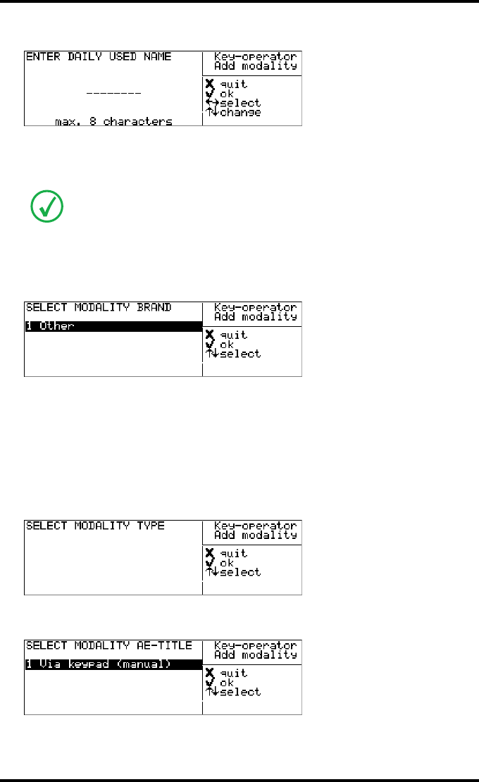
88 2900H EN 20071108Advanced operation (Key-operator mode)
DRYSTAR 5500/5503 REFERENCE MANUAL
The ‘Enter modality daily used name’ screen is displayed:
6Enter the modality daily used name (nickname) by means of the arrow keys.
Refer to ‘Data entry’ on page 33. Make sure not to enter more than 8 characters.
7Press the Confirm key to store the data, or the Escape key to quit the procedure
without any changes.
The ‘Select modality brand’ screen is displayed:
8Press the Up/Down arrow keys to select the appropriate modality brand name.
•In case you have selected ‘Other’, the Modality AE-title will be linked with the
default settings. Proceed with step 10.
9Press the Confirm key to store the data, or the Escape key to quit the procedure
without any changes.
The ‘Select modality type’ screen is displayed:
10 The ‘select modality AE-title’ screen is displayed:
A blank daily used modality name is not allowed.
2 Philips
3 Fuji
4 Siemens
1 MXVIEW
2 MX8000
2 <Modality name>
3 <Modality name>
4 <Modality name>
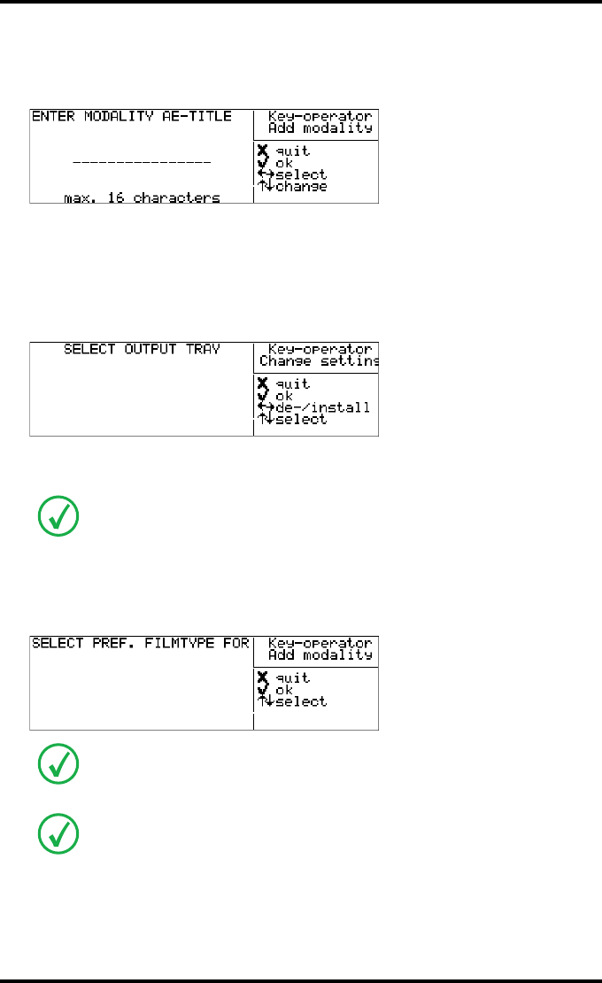
89
2900H EN 20071108 Advanced operation (Key-operator mode)
DRYSTAR 5500/5503 REFERENCE MANUAL
11 Press the Up/Down arrow keys to select the appropriate modality AE-title.
•In case you have selected ‘1 Enter via keypad (manual)’, the ‘Enter modality AE-
title’ screen is displayed:
Enter the Modality AE-title by means of the arrow keys. Refer to ‘Data entry’ on
page 33. Make sure not to enter more than 16 characters.
12 Press the Confirm key to store the data, or the Escape key to quit the procedure
without any changes.
The ‘Select output tray for <daily name or AE-title>’ screen will appear:
Press the Up/Down arrow keys to select the output tray. You can (de)activate
the selected output tray with the Left/Right arrow keys.
13 Press the Confirm key to store the data, or the Escape key to quit the procedure
without any changes.
The ‘Select preferred film type for <daily name or AE-title>’ screen will appear:
Activated output trays are marked with an *.
‘DRYSTAR DT 2 Mammo’ is only shown in the list when the option for the
mammography application is activated. Refer to ‘Options and accessories’ on
page 235.
You can find the film type on the film packaging, e.g. ‘DRYSTAR DT 2 C’.
<daily name or AE-title>
*position 1 (upper)
position 2
posiiton 3
*
p
osition 4
(
lower
)
<daily name or AE-title>
1*DRYSTAR DT 2 B
2 DRYSTAR DT 2 C
3 DRYSTAR DT 2 Mammo
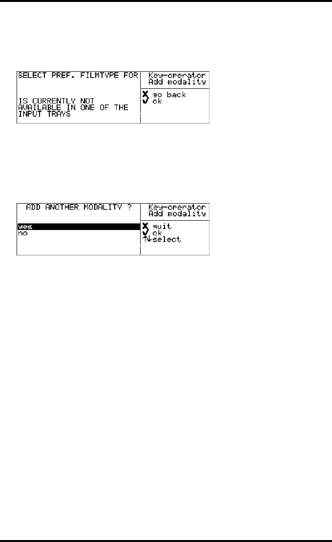
90 2900H EN 20071108Advanced operation (Key-operator mode)
DRYSTAR 5500/5503 REFERENCE MANUAL
14 Press the Up/Down arrow keys to select the preferred film type for this
modality.
In case the current film type in the trays does not match the selected film type the
following message is displayed:
15 Press the Confirm key to store the data, or the Escape key to quit the procedure
without any changes.
The data entry for the new modality is finished now.
The printer will ask you if you want to add another modality:
16 If you wish to add another modality, select Yes and press the Confirm key. You
will be taken back to step 4 to repeat the procedure.
17 If you do not wish to add another modality, select No and press the Confirm key,
or press the Escape key. The printer will return to the Network-Dicom menu.
<Modality name>
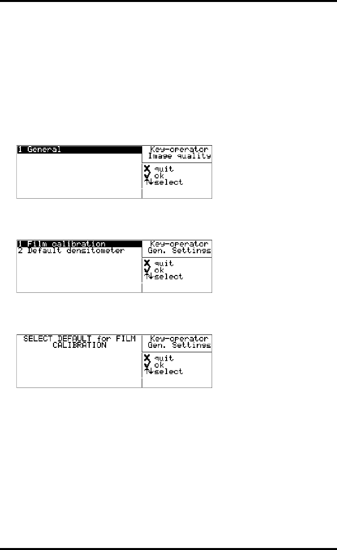
91
2900H EN 20071108 Advanced operation (Key-operator mode)
DRYSTAR 5500/5503 REFERENCE MANUAL
Changing the image quality settings
Changing general image quality settings - Film calibration
1Perform steps 1 and 2 of the ‘Accessing the Change settings menu’ procedure on
page 70.
2On the ‘Change setting’ screen, press the Down key four times, followed by the
Confirm key to select ‘Image quality’.
The following screen will appear:
3Press the Confirm key to select ‘General’.
The ‘General settings’ screen will appear:
4Press the Confirm key to select ‘Film calibration’.
The ‘Select default for film calibration’ screen is displayed:
This setting is by default set to ON and will apply to every modality.
The current setting is marked with an *.
2 <Modality name>
3 <Modality name>
4 <Modality name>
5 <Modality name>
6 <Modality name>
7 <Modality name>
*ON
OFF
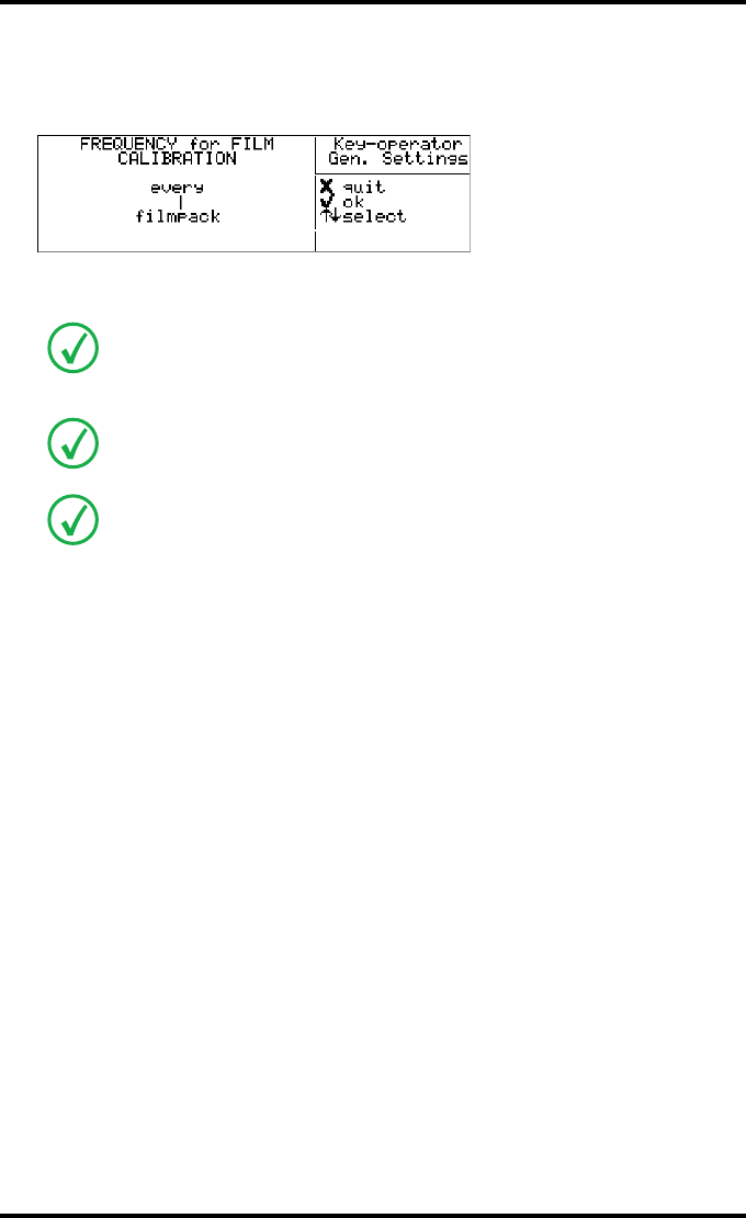
92 2900H EN 20071108Advanced operation (Key-operator mode)
DRYSTAR 5500/5503 REFERENCE MANUAL
5Press the Up/Down arrow keys to select the preferred film calibration default.
When the setting is ON, the Drystar 5500 will ask you to enter the calibration
frequency:
Enter the calibration frequency by means of the Up/Down arrow keys. Refer to ‘Data
entry’ on page 33.
6Press the Confirm key to store the data, or the Escape key to quit the procedure
without any changes.
1 pack = 100 sheets
E.g., if the frequency is set to 5, this means that a film calibration is executed
automatically every 5 packs or every 500 sheets.
You can specify to perform an automatic film calibration after loading every “n“
film packs.
For more information on film calibration settings: refer to ‘Understanding the
calibration policy and the calibration initiation’ on page 221.
5
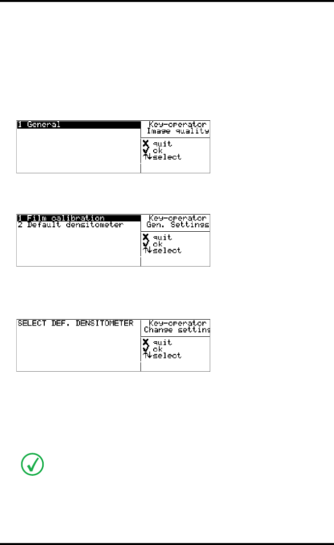
93
2900H EN 20071108 Advanced operation (Key-operator mode)
DRYSTAR 5500/5503 REFERENCE MANUAL
Changing general image quality settings - Default densitometer
1Perform steps 1 and 2 of the ‘Accessing the Change settings menu’ procedure on
page 70.
2On the ‘Change setting’ screen, press the Down key four times, followed by the
Confirm key to select ‘Image quality’.
The following screen will appear:
3Press the Confirm key to select ‘General’.
The ‘General settings’ screen will appear:
4Press the Down key once, followed by the Confirm key to select ‘Default
densitometer’.
The ‘Default densitometer’ screen is displayed:
The current default densitometer is marked with an *.
5Press the Up/Down arrow keys to select the default densitometer.
6Press the Confirm key to store the data, or the Escape key to quit the procedure
without any changes.
All shown densities will vary slightly according to the densitometer selection. Refer
to ‘Drystar media density response data’ on page 237.
2 <Modality name>
3 <Modality name>
4 <Modality name>
5 <Modality name>
6 <Modality name>
7 <Modality name>
* Macbeth TR924
Gretag
X-Rite 301
X-Rite 310
X-Rite 331
X-Rite 341
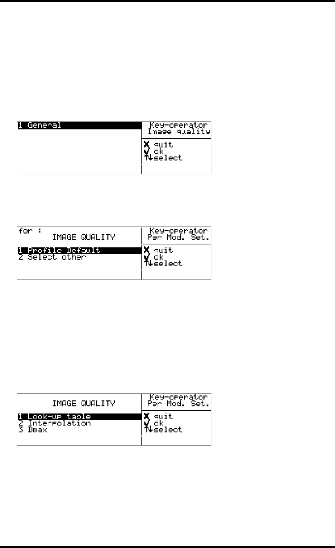
94 2900H EN 20071108Advanced operation (Key-operator mode)
DRYSTAR 5500/5503 REFERENCE MANUAL
Changing Image quality setting for a modality - Selecting a lookup table
1Perform steps 1 and 2 of the ‘Accessing the Change settings menu’ procedure on
page 70.
2On the ‘Change settings’ screen, press the Down key four times, followed by the
Confirm key to select ‘Image quality’.
The following screen will appear:
3Press the Up/Down arrow keys to select the modality for which you want to
change the image quality settings.
The ‘Image quality’ screen for the selected modality is displayed:
4Do one of the following:
•If you want to attribute the default profile, select ‘Profile default’ and press the
Confirm key.
You return to the screen of step 2.
•If you want to add a custom profile, select ‘Select other’ and press the Confirm key.
Proceed with step 5.
5The ‘Image quality’ screen for the selected modality is displayed:
2 <Modality name>
3 <Modality name>
4 <Modality name>
5 <Modality name>
6 <Modality name>
7 <Modality name>
<Modality name>
<Modality name>
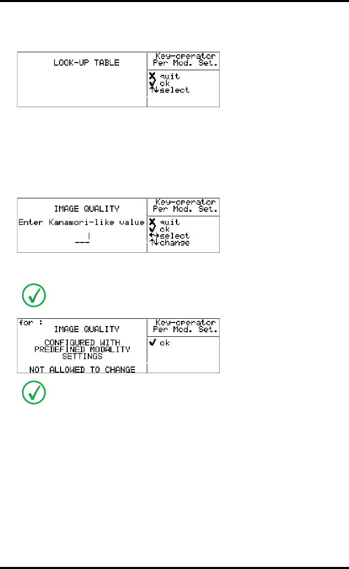
95
2900H EN 20071108 Advanced operation (Key-operator mode)
DRYSTAR 5500/5503 REFERENCE MANUAL
6Press the Confirm key to select ‘Look-up table’.
The ‘Look-up table’ screen for the selected modality is displayed:
7Press the Up/Down arrow keys to select the desired lookup table.
8Press the Confirm key to store the data, or the Escape key to quit the procedure
without any changes.
•In case Kanamori-like is selected, change the Kanamori-value.
An additional screen for the Kanamori-like value is displayed:
All Kanamori-like curves are selectable starting from 75 until 220 in steps of 1 unit.
The activated setting is marked with an *.
In case a number of settings for a modality were set via a remote computer, you will
not be able to change the image quality information for this modality manually. If
this is the case, the following screen will appear:
In case the image quality parameters need to be changed for this modality, please
use the DICOM Configuration tool, in the Specialist or Service mode (specialist
mode available only via remote network PC). You can also delete this modality
(refer to ‘Removing a modality’ on page 86) and create a new modality with the
same name. For this new modality new parameters can be assigned via the local
keypad.
<Modality name>
1 Kanamori
2 Linear
3 Kanamor-like (100)
<Modality name>
100
<Modality name>
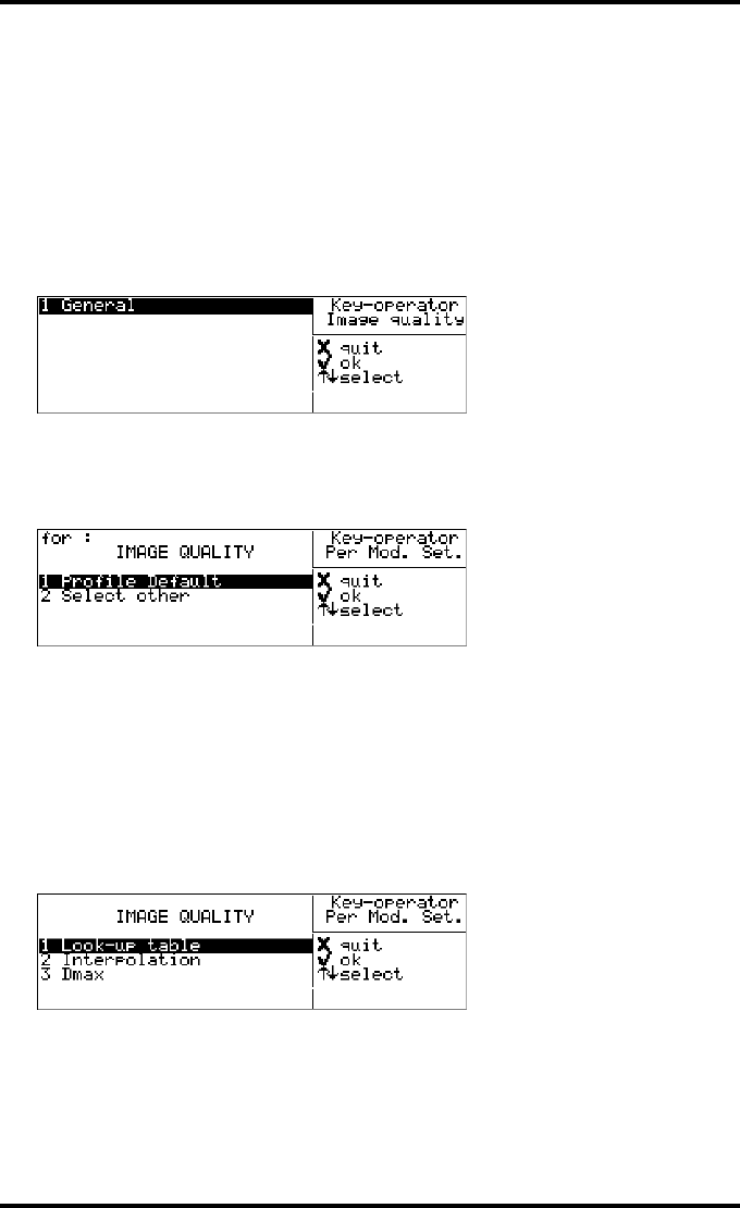
96 2900H EN 20071108Advanced operation (Key-operator mode)
DRYSTAR 5500/5503 REFERENCE MANUAL
Changing Image quality setting for a modality - Changing the Interpola-
tion
1Perform steps 1 and 2 of the ‘Accessing the Change settings menu’ procedure on
page 70.
2On the ‘Change setting’ screen, press the Down key four times, followed by the
Confirm key to select ‘Image quality’.
The following screen will appear:
3Press the Up/Down arrow keys to select the modality for which you want to
change the image quality settings.
The ‘Image quality’ screen for the selected modality is displayed:
4Do one of the following:
•If you want to attribute the default profile, select ‘Profile default’ and press the
Confirm key.
You will return to the screen of step 2.
•If you want to add a custom profile, select ‘Select other’ and press the Confirm key.
Proceed with step 5.
5The ‘Image quality’ screen for the selected modality is displayed:
2 <Modality name>
3 <Modality name>
4 <Modality name>
5 <Modality name>
6 <Modality name>
7 <Modality name>
<Modality name>
<Modality name>
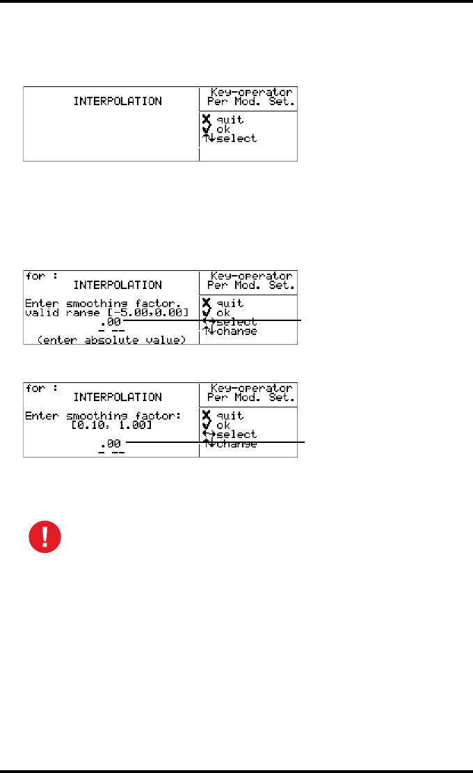
97
2900H EN 20071108 Advanced operation (Key-operator mode)
DRYSTAR 5500/5503 REFERENCE MANUAL
6On the ‘Image quality’ screen press the Down key once, followed by the Confirm
key to select ‘Interpolation’.
The ‘Interpolation’ screen for the selected modality is displayed:
The current interpolation setting for the selected modality is marked with an *.
7Press the Up/Down arrow keys to select the desired Interpolation setting for
this modality.
•If you select “Cubic Hi-Res” the following screen will appear, allowing you to adjust
the smoothing factor:
•If you select “CubicBell” the following screen will appear, allowing you to adjust
the smoothing factor:
8Press the Confirm key to store the data, or the Escape key to quit the procedure
without any changes.
The user should be aware that the interpolation values differ when the
A#Sharp feature is deactivated. The A#Sharp feature, which is a
technology that enhances the image sharpness, is active by default. For
more information about (de)activating the A#Sharp feature, refer to the
Drystar 5500/5503 Service manual.
<Modality name>
1 CubicBell
2*Cubic Hi-Res
3 Linear
4 Replication
5 None
<Modality name>
Default 0.70
<Modality name>
Default 0.90

98 2900H EN 20071108Advanced operation (Key-operator mode)
DRYSTAR 5500/5503 REFERENCE MANUAL
Changing Image quality setting for a modality - Changing the maximum
density (Dmax)
1Perform steps 1 and 2 of the ‘Accessing the Change settings menu’ procedure on
page 70.
2On the ‘Change setting’ screen, press the Down key four times, followed by the
Confirm key to select ‘Image quality’.
The following screen will appear:
3Press the Up/Down arrow keys to select the modality for which you want to
change the image quality settings.
The ‘Image quality’ screen for the selected modality is displayed:
4Do one of the following:
•If you want to attribute the default profile, select ‘Profile default’ and press the
Confirm key.
You will return to the screen of step 2.
•If you want to add a custom profile, select ‘Select other’ and press the Confirm key.
Proceed with step 5.
5The ‘Image quality’ screen for the selected modality is displayed:
2 <Modality name>
3 <Modality name>
4 <Modality name>
5 <Modality name>
6 <Modality name>
7 <Modality name>
<Modality name>
<Modality name>

99
2900H EN 20071108 Advanced operation (Key-operator mode)
DRYSTAR 5500/5503 REFERENCE MANUAL
6On the ‘Image quality’ screen press the Down key twice, followed by the
Confirm key to select ‘Dmax’.
The ‘Dmax (maximum density)’ screen for the selected modality is displayed:
All maximum densities are selectable starting from 2.75 until 3.20 in steps of 0.05
units. The current setting for the selected modality is marked with an *.
7Press the Up/Down arrow keys to select the desired Maximum Density setting
for this modality.
8Press the Confirm key to store the data, or the Escape key to quit the procedure
without any changes.
The maximum density will be limited to the maximum density of the media.
<Modality name>
*2.80
2.85
2.90
2.95
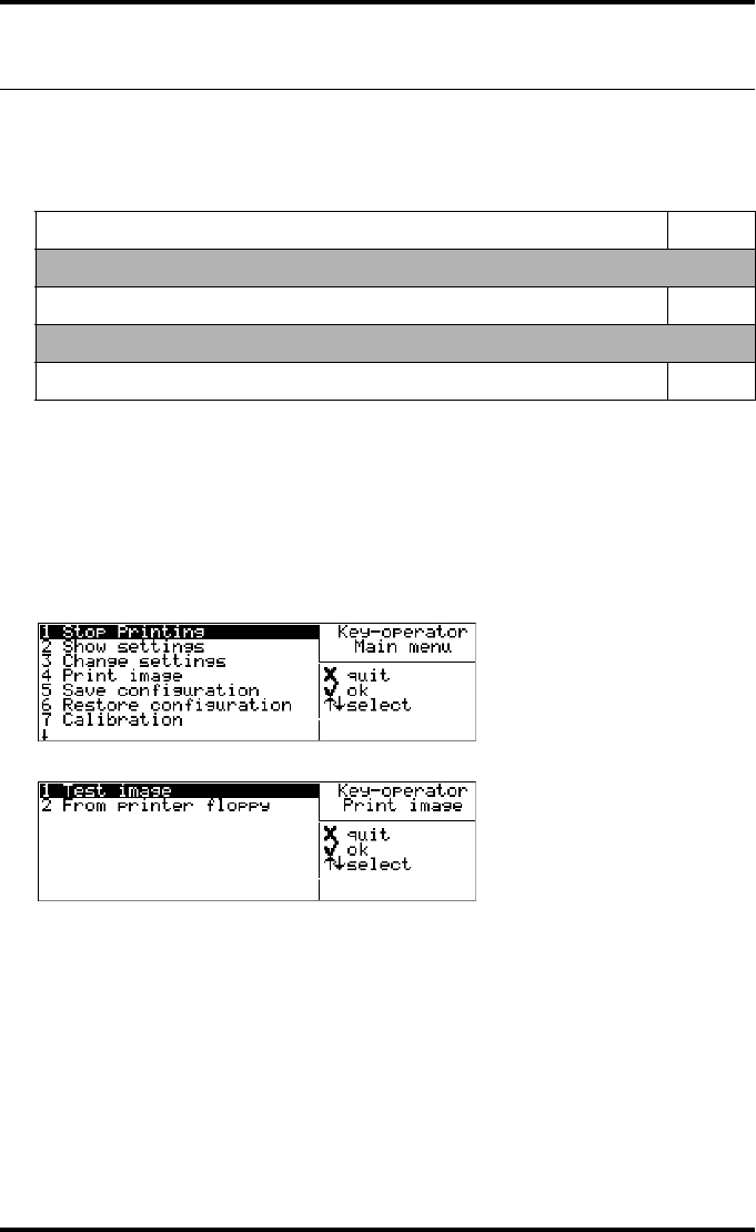
100 2900H EN 20071108Advanced operation (Key-operator mode)
DRYSTAR 5500/5503 REFERENCE MANUAL
Printing images
A number of ‘test’ images can be printed, either from floppy disk or from the
hard disk:
Accessing the Print images menu
1Press the Key-operator key to enter the Key-operator mode.
2On the Key-operator main menu, press the Down key three times followed by
the Confirm key to select ‘Print image’.
The Print image menu is displayed:
3Press the Escape key to return to the Key-operator main menu.
4Press the Escape key to quit the Key-operator mode.
Show settings Page
Test image
‘Printing test images from the hard disk’ 101
Floppy disk
‘Printing files from printer floppy’ 102
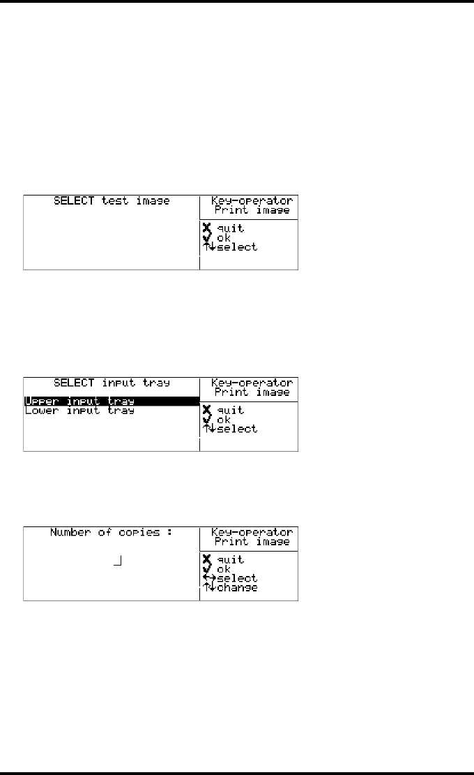
101
2900H EN 20071108 Advanced operation (Key-operator mode)
DRYSTAR 5500/5503 REFERENCE MANUAL
Printing test images from the hard disk
Test images are useful for checking the print quality. The Drystar 5500 offers
a number of built-in test images stored on the hard disk.
1Perform steps 1 to 2 of the ‘Accessing the Print images menu’ procedure on
page 100 to select the ‘Print image’ screen.
2On the ‘Print image’ menu, press the Confirm key to select ‘Test image’.
The ‘Select test image’ screen is displayed:
3Press the Up/Down arrow keys to select the desired test image, followed by the
Confirm key.
4Define the input tray for printing.
The ‘Select input tray’ screen is displayed:
5Press the Up/Down arrow keys to select the desired input tray, followed by the
Confirm key.
The ‘Number of copies’ screen is displayed:
6Press the arrow keys to increment/decrement the number. Press the Left/Right
arrow keys to move through the field.
For more info, refer to ‘Data entry’ on page 33.
1 smpte_lin.tif
2 smpte_1300.tif
3 smpte_kan.tif
4 Artefac_5500.tif
5 TG18QC.tif
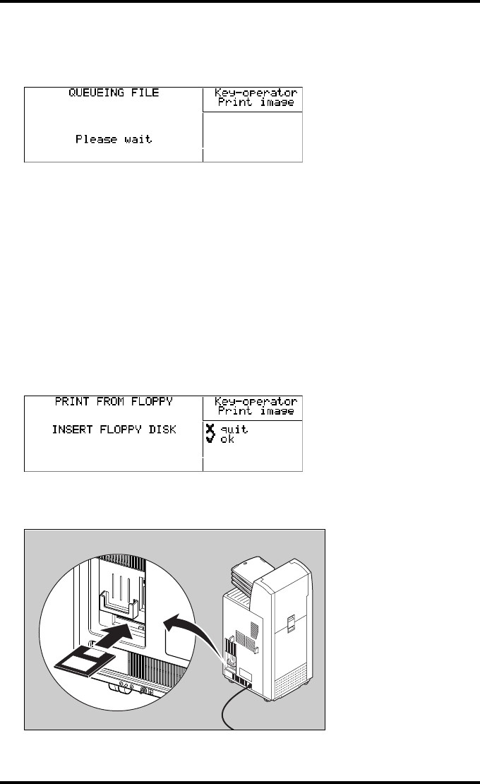
102 2900H EN 20071108Advanced operation (Key-operator mode)
DRYSTAR 5500/5503 REFERENCE MANUAL
7Press the Confirm key to confirm the number of copies.
The ‘Queuing file’ screen will be shown to indicate to the operator that the printing
action from floppy is accepted and in process:
After about five seconds this screen will disappear.
Printing files from printer floppy
TIFF images stored on a floppy disk can be printed using the ‘Print from
floppy’ function.
1Perform steps 1 to 2 of the ‘Accessing the Print images menu’ procedure on
page 100 to select the ‘Print image’ screen.
2On the Print image menu, press the Down key once, followed by the Confirm
key to select ‘From floppy’.
The ‘Print from floppy’ screen is displayed:
3Insert the floppy disk containing the TIFF file(s) you want to be printed.
The drive is located at the rear of the printer.
<filename>
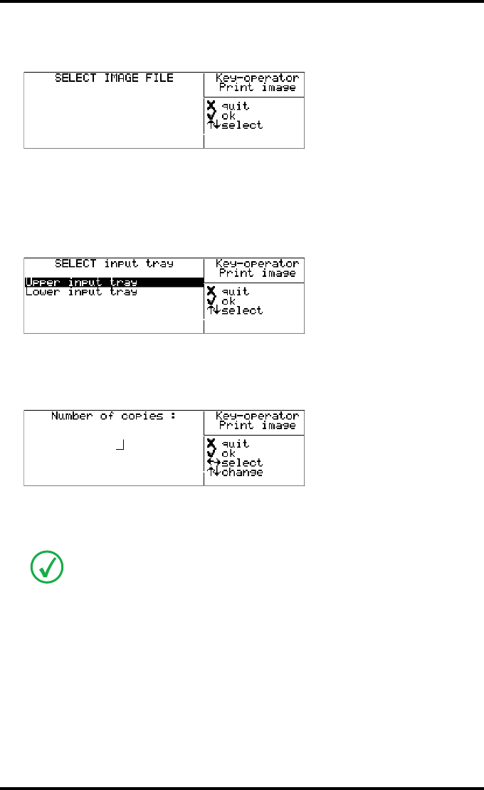
103
2900H EN 20071108 Advanced operation (Key-operator mode)
DRYSTAR 5500/5503 REFERENCE MANUAL
4Press the Confirm key to continue, or the Escape key to quit.
The ‘Select image-file’ screen is displayed:
5Press the Up/Down arrow keys to select the desired .tif-file, followed by the
Confirm key.
6Define the input tray for printing.
The ‘Select input tray’ screen is displayed:
7Press the Up/Down arrow keys to select the desired input tray, followed by the
Confirm key.
The ‘Number of copies’ screen is displayed:
8Press the arrow keys to increment/decrement the number. Press the Left/Right
arrow keys to move through the field.
For more info, refer to ‘Data entry’ on page 33.
1 User image1.tif
2 User image1.tif
3 User image1.tif
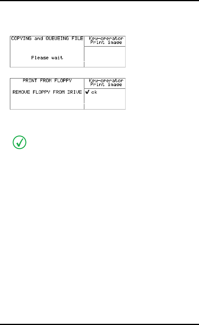
104 2900H EN 20071108Advanced operation (Key-operator mode)
DRYSTAR 5500/5503 REFERENCE MANUAL
9Press the Confirm key to confirm the number of copies.
The ‘Copying and Queuing file’ screen will be shown to indicate to the operator that
the (printing) action is accepted and in progress:
After about 20 seconds the following screen appears:
10 Remove the floppy disk from the drive and press the Confirm key to continue.
The print job is stored in the print queue.
Alternatively, you can print images directly from a connected Remote PC to the
printer. Refer to ‘Starting the remote session’ on page 173.
<filename>
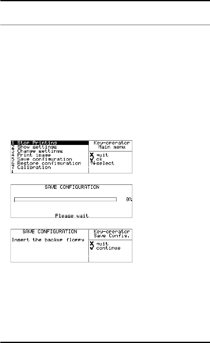
105
2900H EN 20071108 Advanced operation (Key-operator mode)
DRYSTAR 5500/5503 REFERENCE MANUAL
Saving the configuration settings
Each time the settings have been changed and confirmed, an automatic back-
up of the new configuration is made on the hard disk. You will also be asked to
create a back-up floppy.
It is also possible (and recommended) to regularly make a back-up of the
printer settings to ensure safe restoring of the values when required.
Saving the current configuration
1Press the Key-operator key to enter the Key-operator mode.
2On the Key-operator main menu, press the Down key four times, followed by
the Confirm key to select ‘Save configuration’.
The following screen appears:
When 100% is reached, the following the ‘Save configuration’ screen is displayed:
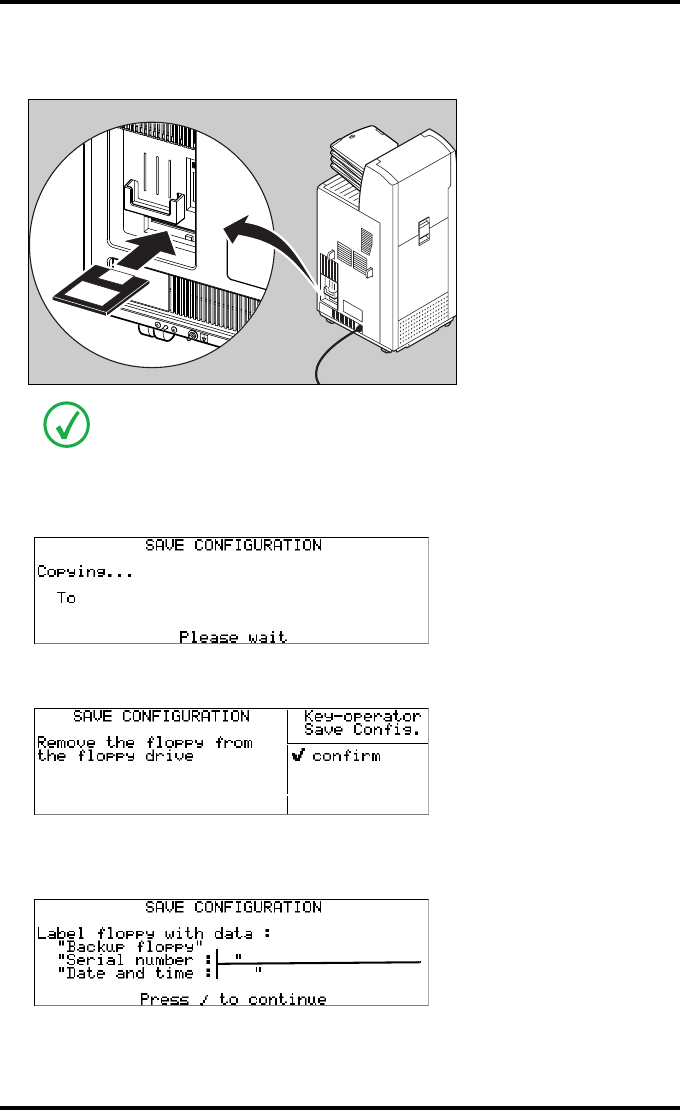
106 2900H EN 20071108Advanced operation (Key-operator mode)
DRYSTAR 5500/5503 REFERENCE MANUAL
3Insert an empty floppy disk.
The drive is located at the rear of the printer.
4Press the Confirm key to continue.
A second ‘Save configuration’ screen is displayed.
The printer saves the configuration on the floppy disk.
The following screen is displayed:
5Remove the floppy disk and press the Confirm key.
The following screen is displayed:
6Press the Confirm key. The program will return to the main Key-operator menu.
For the back-up, an empty floppy disk is required (formatted, IBM-compatible,
2HD).
D:/<path><filename>
A:/<path><filename>
e.g.
1024
18-AUG-2005 11:07:18
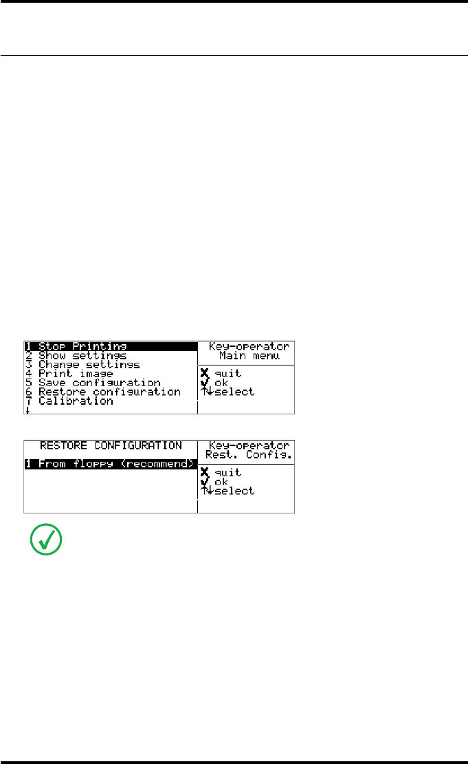
107
2900H EN 20071108 Advanced operation (Key-operator mode)
DRYSTAR 5500/5503 REFERENCE MANUAL
Restoring the configuration settings
When necessary, you can restore the configuration settings of the printer from
a previously made back-up copy.
The following functions are provided for restoring a back-up copy of the
configuration files:
•‘Restoring printer settings from the back-up floppy disk’ (page 108).
•‘Restoring printer settings from the hard disk’ (page 110).
Accessing the restore configuration menu
1Press the Key-operator key to enter the Key-operator mode.
2On the Key-operator main menu, press the Down key five times, followed by the
Confirm key to select ‘Restore configuration’.
The ‘Restore configuration’ screen is displayed:
3Press the Escape key to return to the Key-operator main menu.
4Press the Escape key to quit the Key-operator mode.
This menu is the starting point for restoring printer settings (see below).
2 Settings 10/05/04 10:55
3 Settings 08/05/04 08:05
4 Settings 08/05/04 07:45
5 Settings 08/05/04 07:31
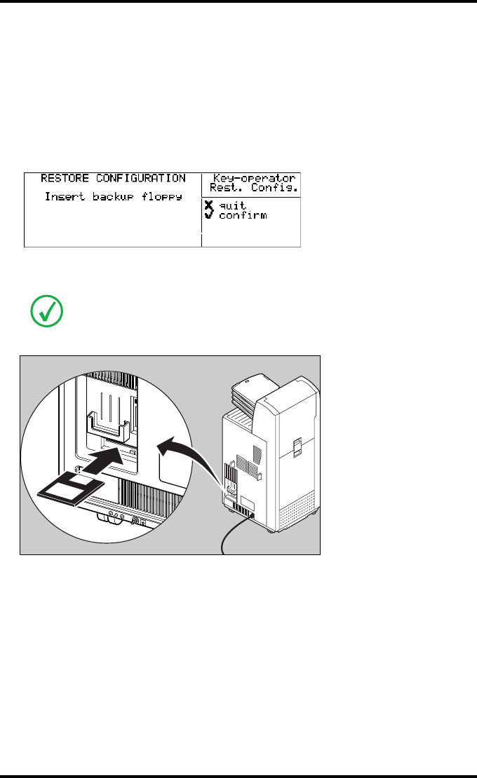
108 2900H EN 20071108Advanced operation (Key-operator mode)
DRYSTAR 5500/5503 REFERENCE MANUAL
Restoring printer settings from the back-up floppy disk
1Perform steps 1 to 2 of the ‘Accessing the restore configuration menu’ procedure
on page 107 to select the ‘Restore Configuration’ screen.
2Press the Confirm key in the ‘Restore configuration’ screen to select ‘From
floppy (recommend)’.
The following screen is displayed:
3Insert the floppy disk which contains a back-up of the printer settings.
The drive is located at the rear of the printer.
Make sure that you insert the correct floppy disk, containing the printer settings
you want to restore.
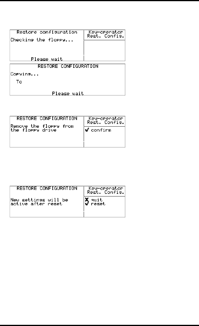
109
2900H EN 20071108 Advanced operation (Key-operator mode)
DRYSTAR 5500/5503 REFERENCE MANUAL
4Press the Confirm key to continue.
The following screens appear successively:
The printer restores the configuration on the hard disk.
The following screen is displayed.
5Remove the floppy disk.
6Press the Confirm key to continue.
The following screen is displayed.
Press the Confirm key to reset the printer. After the reset, the new settings will be
active.
Press the Escape key to quit the application. The old settings will remain active until
the next reset.
<type of information>
A:/<path><filename>
D:/<path><filename>
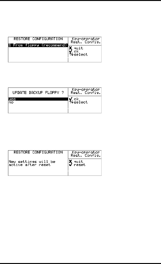
110 2900H EN 20071108Advanced operation (Key-operator mode)
DRYSTAR 5500/5503 REFERENCE MANUAL
Restoring printer settings from the hard disk
1Perform steps 1 to 2 of the ‘Accessing the restore configuration menu’ procedure
on page 107 to select the ‘Restore Configuration’ screen:
2Press the Up/Down arrow keys in the ‘Restore configuration’ screen to select the
required printer settings from the hard disk, followed by the Confirm key.
The following screen is displayed.
If you want to restore the configuration on the back-up floppy, select ‘yes’ and press
the Confirm key. The printer will now enter the ‘Saving the current configuration’
(refer to page 105).
If you only want to restore the configuration on the printer hard disk, select ‘no’ and
press the Confirm key.
After the restore operation, the following screen is displayed.
Press the Confirm key to reset the printer. After the reset, the new settings will be
active.
Press the Escape key to quit the application. The old settings will remain active until
the next reset.
2 Settings 10/05/04 10:55
3 Settings 08/05/04 08:05
4 Settings 08/05/04 07:45
5 Settings 08/05/04 07:31
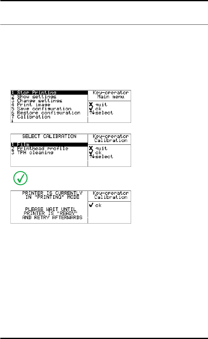
111
2900H EN 20071108 Advanced operation (Key-operator mode)
DRYSTAR 5500/5503 REFERENCE MANUAL
Performing the calibration procedures
Accessing the calibration menu
1Press the Key-operator key to enter the Key-operator mode.
2Press the Down key six times, followed by the Confirm key to select
‘Calibration’.
The ‘Select Calibration’ screen appears:
3Press the Escape key to return to the Key-operator main menu.
4Press the Escape key to quit the Key-operator mode.
In case the printer is in printing mode, a screen will be presented that the
calibration cannot be done now, but has to be reactivated later.
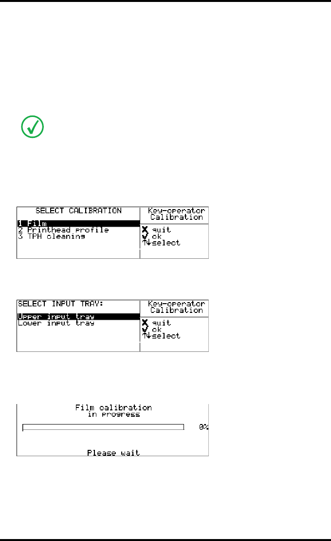
112 2900H EN 20071108Advanced operation (Key-operator mode)
DRYSTAR 5500/5503 REFERENCE MANUAL
Film calibration
The film calibration combines Dmax and sensitometry calibration, and is
activated as one single procedure. Separate Dmax and sensitometry
calibration steps are not required.
For more general information on maintaining image quality, refer to
‘Maintaining image quality and resolving Image quality problems’ on page 220.
To start the film calibration:
1Perform step 1 to 2 of the ‘Accessing the calibration menu’ procedure on page 111
to select the ‘Calibration’ screen.
2Press the Confirm key to select ‘Film’.
The ‘Select input tray’ screen appears:
3Press the Up/Down arrow keys to select an input tray, followed by the Confirm
key (e.g. choose upper input tray).
The ‘Film calibration in progress’ screen appears:
The counter indicates the progress of the calibration process. The calibration film is
measured automatically by the built-in MDM (Macro DensitoMeter). The
Drystar 5500 is being calibrated during the printing process.
In the procedure, we will assume a film calibration on the upper input tray. The
procedure for the lower input tray is identical.
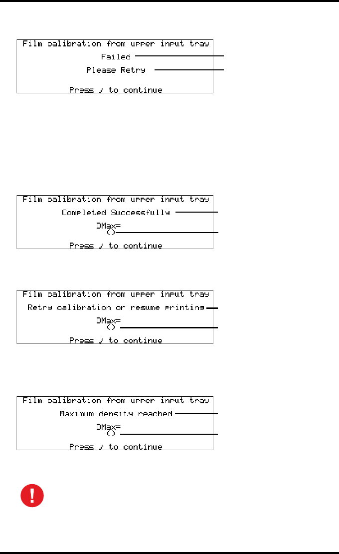
113
2900H EN 20071108 Advanced operation (Key-operator mode)
DRYSTAR 5500/5503 REFERENCE MANUAL
4In case the film calibration has failed, the following message will appear.
Press the Confirm key to retry the calibration.
5When the film calibration has completed succesfully, this indicates that the
calibration procedure has been executed succesfully. This does not always mean
that the result of the calibration is succesful.
Three cases are possible:
•Calibration successful, results OK.
The obtained Dmax (x.xx) after calibration is displayed:
•Calibration successful, but Dmax differs more than 2% from the target
value.
The obtained Dmax (x.xx) after calibration is displayed:
•Calibration procedure succesful, but limited by film-Dmax. The obtained
Dmax does not meet the required system Dmax and is limited by the film
sensitometry.
The obtained Dmax (x.xx) after calibration is displayed:
6Press the Confirm key to return to the Calibration menu.
When the calibration process is interrupted, you will have to start the
calibration procedure again. Otherwise, the old calibration parameters
will be used.
Blinking
Blinking
X.XX
Blinking
Default Densitometer
e.g. Macbeth TR924
X.XX
Blinking
Default Densitometer
e.g. Macbeth TR924
X.XX
Blinking
Default Densitometer
e.g. Macbeth TR924

114 2900H EN 20071108Advanced operation (Key-operator mode)
DRYSTAR 5500/5503 REFERENCE MANUAL
7Check the printed test film.
The test film must be similar to the image below.
Density response of Drystar media
Different densitometers can give different results when measuring the same
density area. This is due to spectral differences between the densitometers.
The density values used in this manual are based on the X_Rite 310
densitometer. Values measured with another densitometer can vary from
these values.
It’s possible to change the default densitometer. Refer to Changing general
image quality settings - Default densitometer on page 93. You can also
compare the density values from different densitometers with each other.
Refer to ‘Drystar media density response data’ on page 237.
Non-calibrated or badly calibrated densitometers can result in even larger
differences.
To give the user an idea of the differences given by the most frequently used
densitometers, you can find the measurements for an SMPTE pattern on the
DRYSTAR DT 2 B, DRYSTAR DT 2 C and DRYSTAR DT 2 Mammo films in
Appendix B on page 237.
The calibration film must be free of dust particles or any other artifacts. If
this is not the case, clean the print head and restart the calibration
procedure.
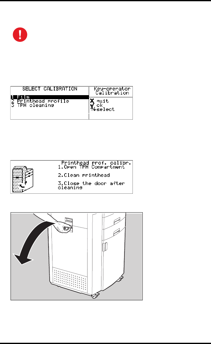
115
2900H EN 20071108 Advanced operation (Key-operator mode)
DRYSTAR 5500/5503 REFERENCE MANUAL
Print head cleaning
To clean the print head:
1Perform step 1 to 2 of the ‘Accessing the calibration menu’ procedure on page 111
to select the ‘Calibration’ screen.
2Press the Down key twice to select ‘TPH cleaning’ and press the Confirm key.
The printer will automatically shut down.
3The ‘print head cleaning’ screen will give instructions on what to do:
4Open the drum compartment door by pulling its handle.
Print head cleaning must be done when image quality problems occur. For
more information on maintaining image quality, refer to ‘Maintaining image
quality and resolving Image quality problems’ on page 220.
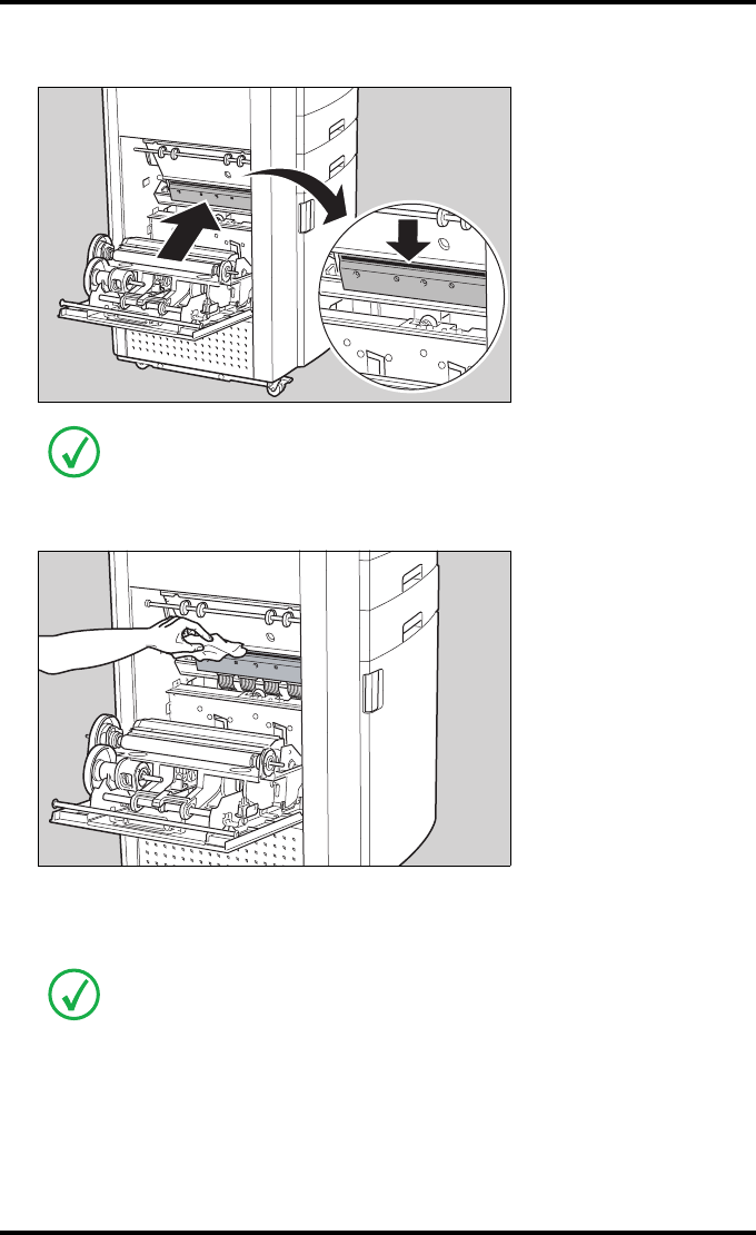
116 2900H EN 20071108Advanced operation (Key-operator mode)
DRYSTAR 5500/5503 REFERENCE MANUAL
5Locate and check on sight the print head resistor line.
6Clean the print head resistor line.
Gently pass over the resistor line a few times with a lint free cloth, slightly moistened
with Isopropyl alcohol or Ethanol. Do this in only one direction, i.e. from left to
right, without lifting the cloth.
Be careful not to touch the print head resistor line.
Do not apply any pressure on the print head because this pressure may cause
damage on the interconnections underneath the print head.

117
2900H EN 20071108 Advanced operation (Key-operator mode)
DRYSTAR 5500/5503 REFERENCE MANUAL
7Close the drum compartment door.
After you have cleaned the print head resistor line and closed the drum compartment
door, the printer will restart automatically.
If residue dust is present as part of the cleaning procedure it will disappear after a
few prints. However, if dust lines persist even after a few prints, the dust rollers
need to be cleaned. Proceed with ‘Cleaning the dust rollers’ on page 188.
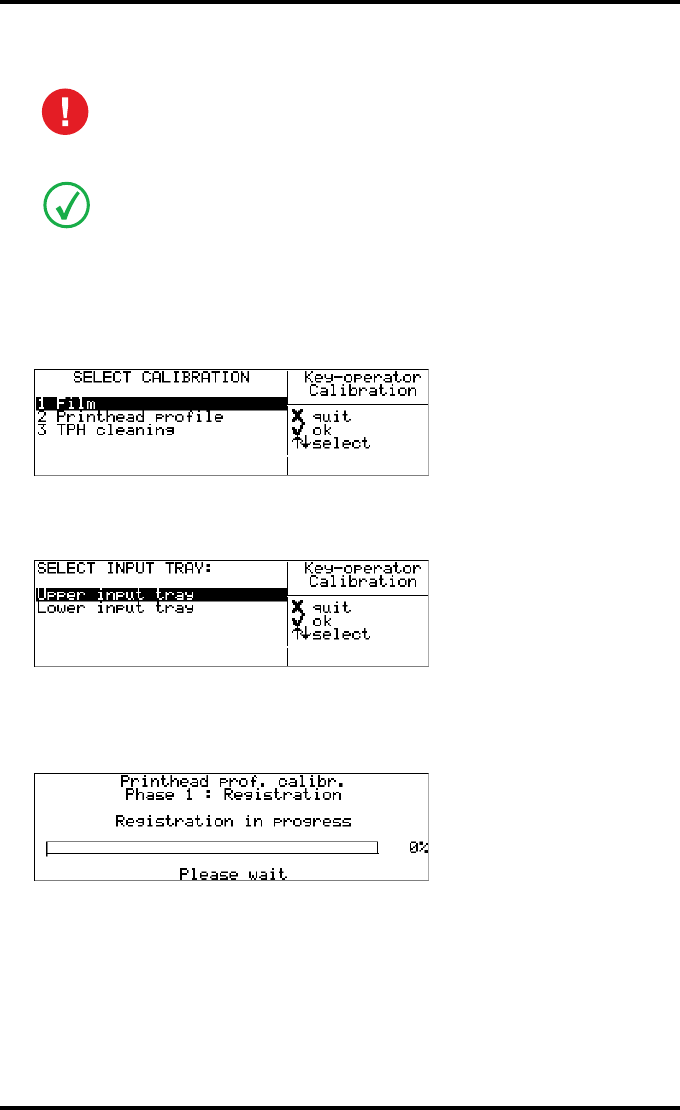
118 2900H EN 20071108Advanced operation (Key-operator mode)
DRYSTAR 5500/5503 REFERENCE MANUAL
Print head profile calibration
To start the manual print head profile calibration:
1Perform step 1 to 2 of the ‘Accessing the calibration menu’ procedure on page 111
to select the ‘Calibration’ screen.
2Press the Down key once to select ‘Printhead profile’, and press the Confirm key.
The ‘Select input tray’ screen appears:
3Press the Up/Down arrow keys to select an input tray, followed by the Confirm
key (e.g. choose upper input tray).
The system will start with Phase 1 of the calibration: Registration:
As a result, the ‘Registration’ print out appears.
Print head profile calibration must be done whenever the profile of the
print head needs to be improved (manual print head profile calibration).
For more information on maintaining image quality, refer to ‘Maintaining
image quality and resolving Image quality problems’ on page 220.
In the procedure, we will assume a print head profile calibration on the upper input
tray. The procedure for the lower input tray is identical.
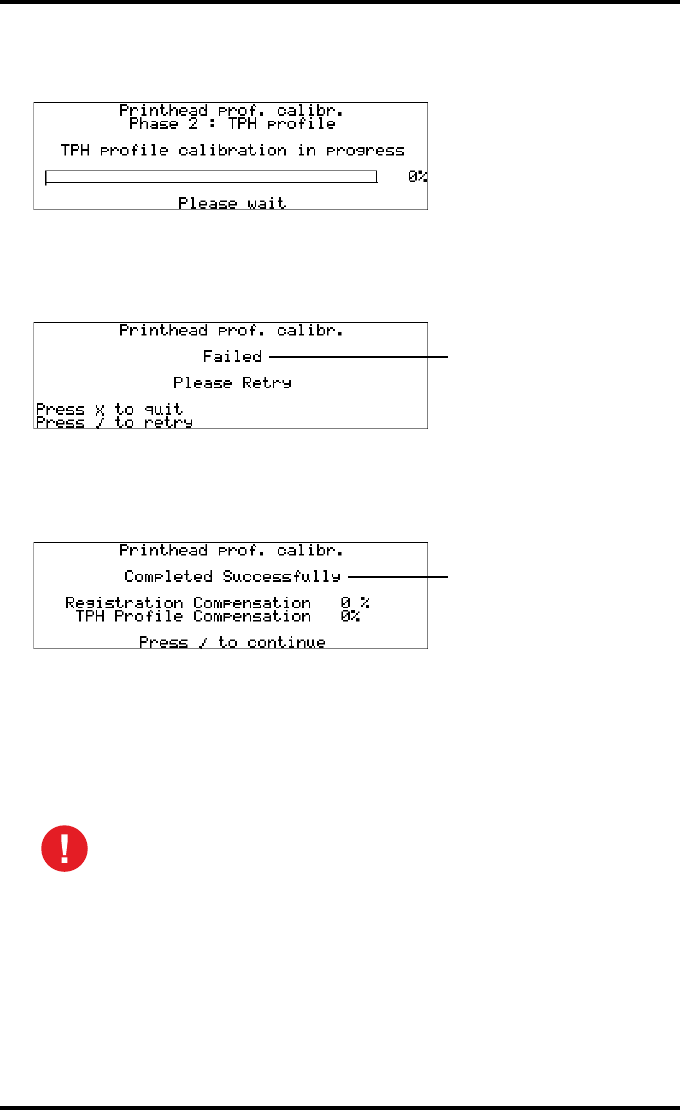
119
2900H EN 20071108 Advanced operation (Key-operator mode)
DRYSTAR 5500/5503 REFERENCE MANUAL
4After registration, the system will continue with Phase 2 of the calibration: the
print head profile calibration:
As a result, the ‘TPH profile’ print out appears.
5In case the print head profile calibration has failed, the following message
appears:
Press the Confirm key to retry the calibration, or the Escape key to quit.
6In case the film calibration has completed successfully, the following message
appears:
•The percentage for the ‘Registration compensation’ reflects the degree to which the
system had to compensate for incorrect horizontal positioning of the built-in
densitometer (100% compensation = maximal correction).
•The percentage for the ‘print head profile compensation’ reflects the degree to
which the system had to compensate for density variations in the print head profile
(100% compensation = maximal correction).
Both values are important for the service technician.
When the calibration process is interrupted, you will have to start the
calibration procedure again. Otherwise, the old calibration parameters
will be used.
Blinking
Blinking
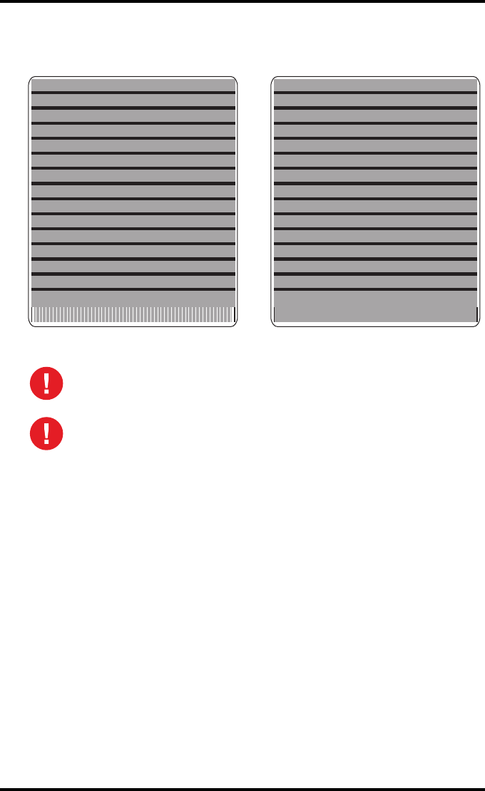
120 2900H EN 20071108Advanced operation (Key-operator mode)
DRYSTAR 5500/5503 REFERENCE MANUAL
7Check the printed test films.
The test films must be similar to the images below.
Remark: the calibration film must be free of dust particles or any other
artifacts. If this is not the case, you must restart the calibration procedure.
If the printed test film does not look similar to the image above, repeat the
print head profile calibration until the result is satisfactory.
TPH profileRegistration
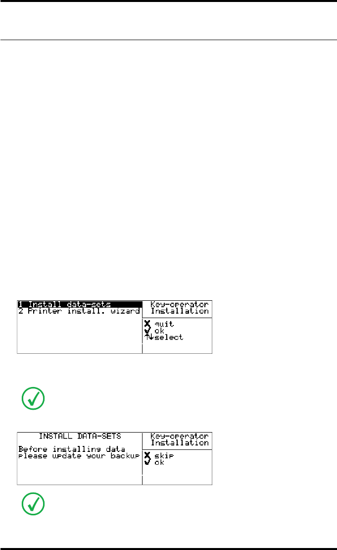
121
2900H EN 20071108 Advanced operation (Key-operator mode)
DRYSTAR 5500/5503 REFERENCE MANUAL
Installation
Upgrading the software
It is possible to install new software or new software components from a
floppy disk onto the hard disk.
Different software (components) can be installed:
•language files,
•modality specific files,
•calibration files,
•...
The new software will be activated after the Installation procedure. The
previously installed software components will be automatically removed
when installing new software or new data.
1Press the Key-operator key to enter the Key-operator mode.
2On the Key-operator main menu, press the Down key seven times, followed by
the Confirm key to select ‘Installation’.
The ‘Installation’ screen will be displayed:
3Press the Confirm key to select ‘Install data-sets’.
The following screen is displayed:
Before the procedure starts, the system suggests you to update your back-up copy of
the current configuration. It is highly recommended to do this, so you can always
restore it in case something should go wrong.
If you do not wish to update your back-up copy, press the Escape key and go to
step 10.
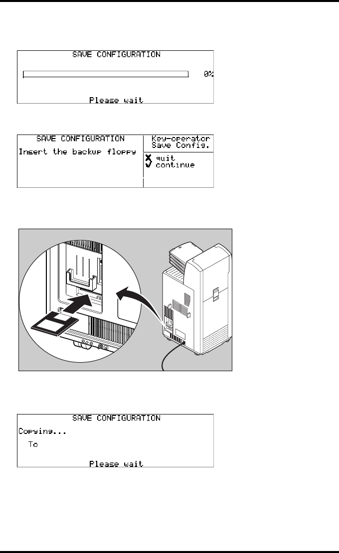
122 2900H EN 20071108Advanced operation (Key-operator mode)
DRYSTAR 5500/5503 REFERENCE MANUAL
4Press the Confirm key to confirm the back-up.
The following screens appears successively:
5After saving, the printer asks you to insert the back-up floppy.
6Insert the back-up floppy disk.
The drive is located at the rear of the printer.
7Press the Confirm key to continue.
The following screen is displayed:
The printer saves the configuration on the back-up floppy disk.
D:/<path><filename>
A:/<path><filename>
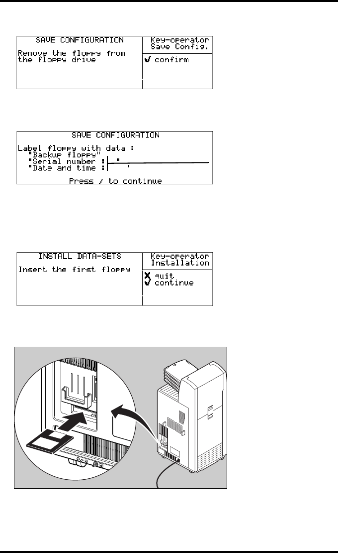
123
2900H EN 20071108 Advanced operation (Key-operator mode)
DRYSTAR 5500/5503 REFERENCE MANUAL
When the writing process has finished, the following screen is displayed:
8Remove the floppy disk and press the Confirm key.
The following screen is displayed:
9Press the Confirm key.
The back-up is finished and the system will now proceed with the actual upgrade.
10 The ‘Install data-sets’ screen is displayed:
11 Insert the (first) floppy disk.
The drive is located at the rear of the printer.
e.g.
1024
18-AUG-2005 11:07:18
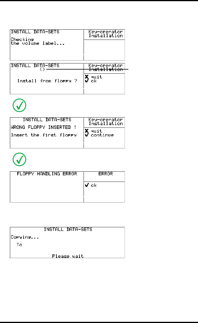
124 2900H EN 20071108Advanced operation (Key-operator mode)
DRYSTAR 5500/5503 REFERENCE MANUAL
12 Press the Confirm key to continue.
The following screens appear successively:
13 Press the Confirm key to continue, or the Escape key to quit.
The printer will copy the new software data onto the hard disk.
In case a wrong disk has been inserted, the following message is displayed:
In case no floppy has been inserted, the following message is displayed:
Print head data
No floppy detected
A:/<path><filename>
D:/<path><filename>
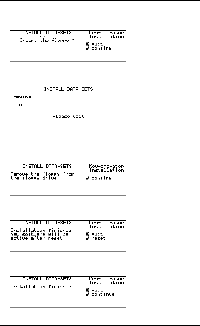
125
2900H EN 20071108 Advanced operation (Key-operator mode)
DRYSTAR 5500/5503 REFERENCE MANUAL
14 When the contents of the floppy is copied onto the hard disk, the following
message asks you to insert the next floppy (if a next one is required):
15 Remove the floppy disk and insert the next floppy disk (‘disk x/y’) when
necessary. Press the Confirm key to continue.
The printer will copy the new software data onto the hard disk.
16 Repeat steps 14 and 15 until all floppy disks have been copied onto the
hard disk.
When all the files have been copied from the last floppy disk, the following screen is
displayed:
17 Remove the last floppy disk and press the Confirm key.
In case the software requires a reset, the following screen will be displayed:
18 Press the Confirm key to reset the printer.
In case the software requires no reset, the following screen will be displayed:
Disk x/y
Print head data
A:/<path><filename>
D:/<path><filename>
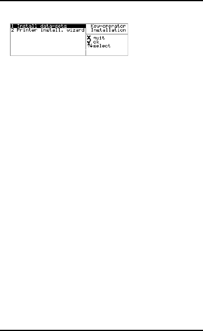
126 2900H EN 20071108Advanced operation (Key-operator mode)
DRYSTAR 5500/5503 REFERENCE MANUAL
19 Press the Confirm key to continue. You will return to the ‘Installation’ screen.

127
2900H EN 20071108 Advanced operation (Key-operator mode)
DRYSTAR 5500/5503 REFERENCE MANUAL
Using the installation wizard
When you install the Drystar 5500, the installation wizard will guide you
through the complete installation procedure.
The Installation wizard consists of three steps:
•‘Entering the printer network settings’ (page 130),
•‘Entering modality-specific settings’ (page 135),
•‘Saving the configuration’ (page 139).
When you have entered the required data, the installation is complete.
In case the display software has been updated (e.g. when installing language files),
the ‘Updating display software’ screen is displayed during the downloading of the
display software:
Although the Installation wizard consists of three separate steps, these steps cannot
be performed separately.
To change the settings once the installation has completed, refer to ‘Changing the
configuration settings’ on page 69.
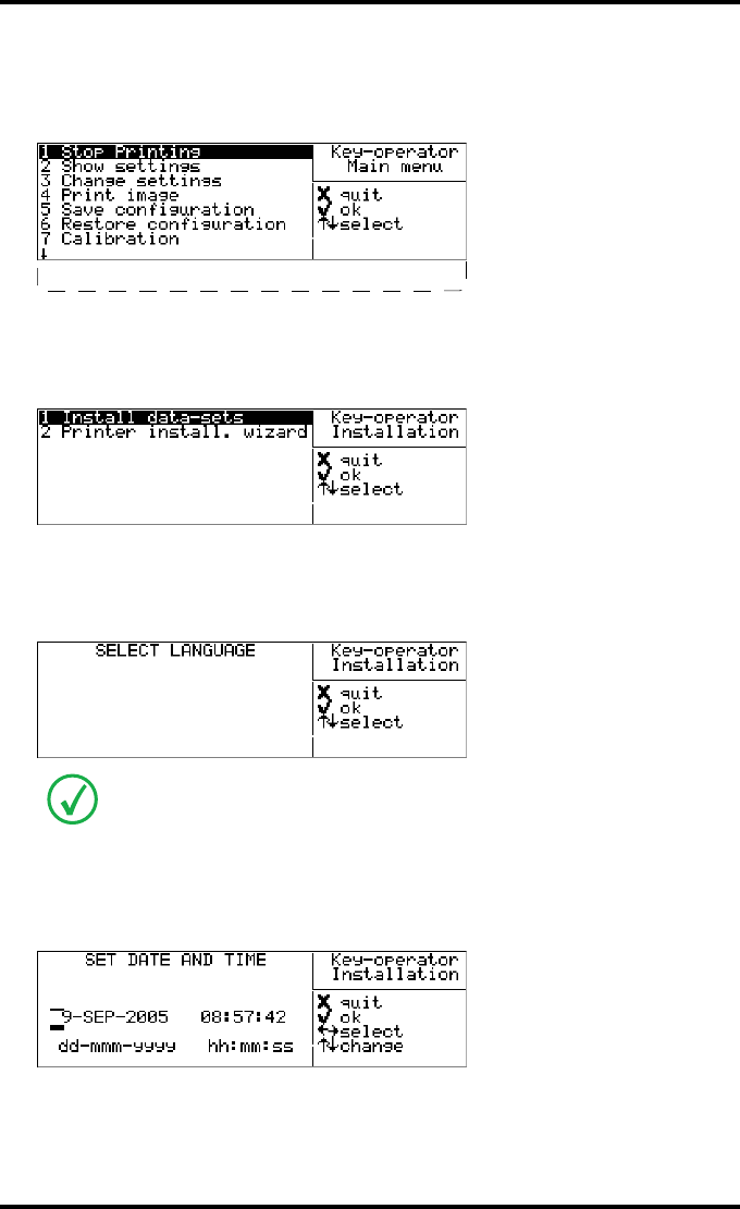
128 2900H EN 20071108Advanced operation (Key-operator mode)
DRYSTAR 5500/5503 REFERENCE MANUAL
Starting the Installation wizard
1Press the Key-operator key to enter the Key-operator mode.
2On the Key-operator main menu, press the Down key seven times, followed by
the Confirm key to select ‘Installation’.
The ‘Installation’ screen will be displayed:
3Press the Down key once, followed by the Confirm key to select ‘Printer instal.
wizard’.
The ‘Select language’ screen is displayed:
4Press the Up/Down arrow keys to select the desired language, followed by the
Confirm key.
The ‘Set date and time’ screen is displayed:
The number of displayed languages depends on the installed dataset. Contact your
local Agfa service organization for the latest Drystar 5500 language availability
status.
7 Installation
8 Quality control
1*English
2 Nederlands
3 Francais
4 Deutsch
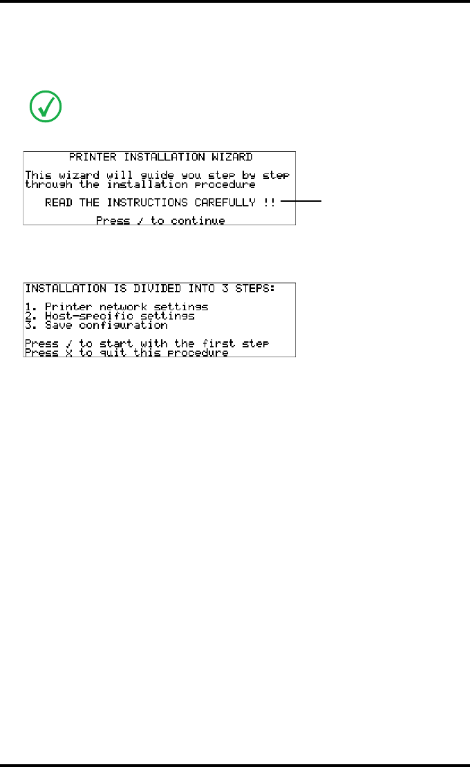
129
2900H EN 20071108 Advanced operation (Key-operator mode)
DRYSTAR 5500/5503 REFERENCE MANUAL
5Press the Up/Down arrow keys to increment/decrement the numbers. Press the
Left/Right arrow keys to move through the fields. Press the Confirm key to store
the data.
The ‘Printer installation wizard’ screen will appear:
6Press the Confirm key to continue.
A screen with information on the sequence of the steps will appear:
7Press the Confirm key to start with the first step or press the Escape key to quit
the procedure.
Refer to ‘Data entry’ on page 33.
Blinking
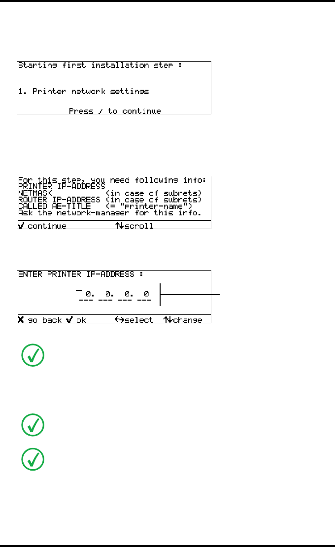
130 2900H EN 20071108Advanced operation (Key-operator mode)
DRYSTAR 5500/5503 REFERENCE MANUAL
Entering the printer network settings
The following introduction screen will appear:
1Press the Confirm key to continue.
An instruction screen will show the information you need to complete this
part of the installation:
2Press the Confirm key to continue.
The ‘Enter printer IP-address’ screen is displayed:
If the IP-address has already been assigned, it will be shown on the display.
3Press the Up/Down arrow keys to increment/decrement the numbers. Press the
Left/Right arrow keys to move through the fields.
When no DHCP server is available and when the IP address of the printer has never
been set, the printer IP address will be set to the APIPA address 169.254.10.10.
Refer to ‘Data entry’ on page 33.
Note that blank spaces will not be filled in.
e.g. 10.233. 93. 46
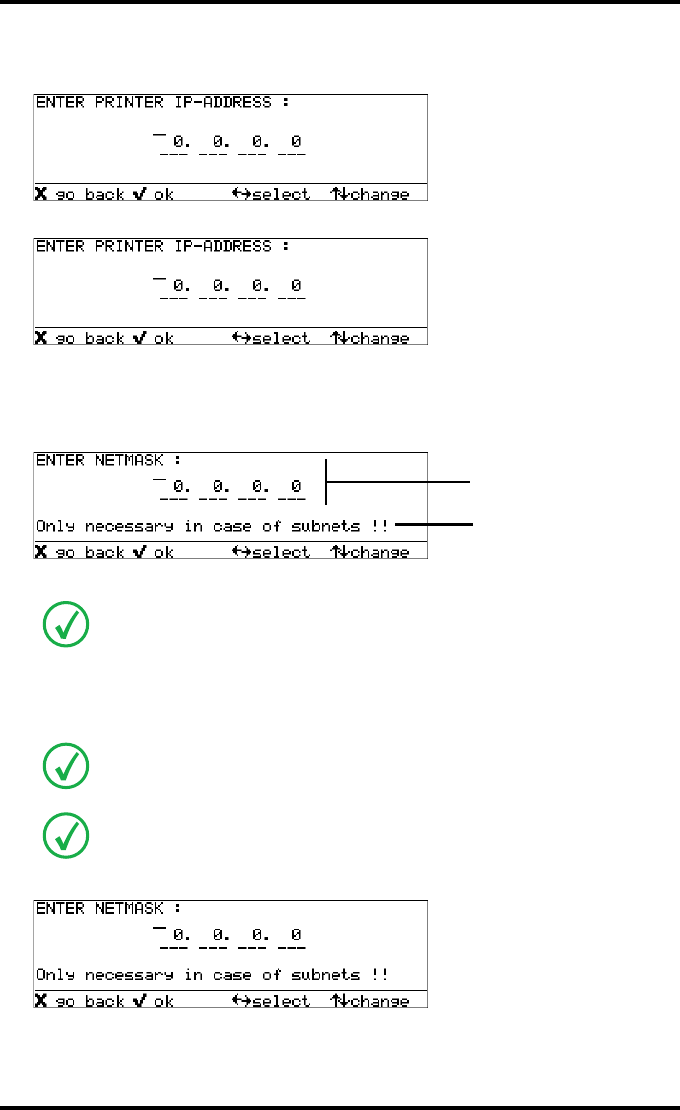
131
2900H EN 20071108 Advanced operation (Key-operator mode)
DRYSTAR 5500/5503 REFERENCE MANUAL
Example: If the IP-address is 120.000.120.120, then the data entry should be as
follows:
Example: If the IP-address is 120.0.120.120, then the data entry should be as follows:
4Press the Confirm key to continue, or the Escape key to return to the previous
step.
The ‘Enter Netmask’ screen is displayed:
If the net mask has already been assigned, it will be shown on the display.
5Press the Up/Down arrow keys to increment/decrement the numbers. Press the
Left/Right arrow keys to move through the fields.
Example: If the netmask is 120.000.120.120, then the data entry should be as follows:
When no DHCP server is available and when the subnet mask of the printer has
never been set, the subnet mask will be set to the APIPA address 255.255.0.0.
Refer to ‘Data entry’ on page 33.
Note that blank spaces will not be filled in.
12 .00 .12 .12
12 . .12 .12
Blinking
e.g. 255.255.252. 0
12 00 12 12
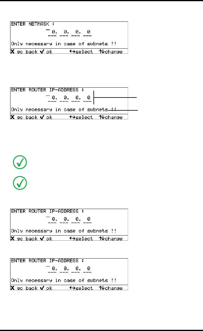
132 2900H EN 20071108Advanced operation (Key-operator mode)
DRYSTAR 5500/5503 REFERENCE MANUAL
Example: If the netmask is 120.0.120.120, then the data entry should be as follows:
6Press the Confirm key to continue, or the Escape key to return to the previous
step.
The ‘Enter Router IP-address’ screen is displayed:
If the Router IP-address has already been assigned, it will be shown on the display.
7Press the Up/Down arrow keys to increment/decrement the numbers. Press the
Left/Right arrow keys to move through the fields.
Example: If the Router IP-address is 120.000.120.120, then the data entry should be
as follows:
Example: If the Router IP-address is 120.0.120.120, then the data entry should be as
follows:
Refer to ‘Data entry’ on page 33.
Note that blank spaces will not be filled in.
12 12 12
Blinking
e.g. 10.233. 92. 1
12 00 12 12
12 12 12
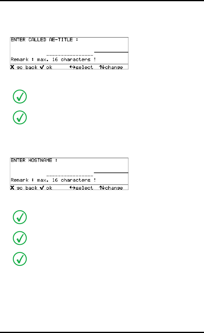
133
2900H EN 20071108 Advanced operation (Key-operator mode)
DRYSTAR 5500/5503 REFERENCE MANUAL
8Press the Confirm key to continue, or the Escape key to return to the previous
step.
The ‘Enter Called AE-title’ screen is displayed:
9Enter the Called AE-title by means of the arrow keys.
10 Press the Confirm key to continue, or the Escape key to return to the previous
step.
The ‘Hostname’ screen is displayed:
11 Enter the Hostname by means of the arrow keys.
Refer to ‘Data entry’ on page 33.
Make sure not to enter more than 16 characters.
Refer to ‘Data entry’ on page 33.
Make sure not to enter more than 16 characters.
Note that blank spaces will not be filled in.
e.g. DS5500
e.g. ds5500
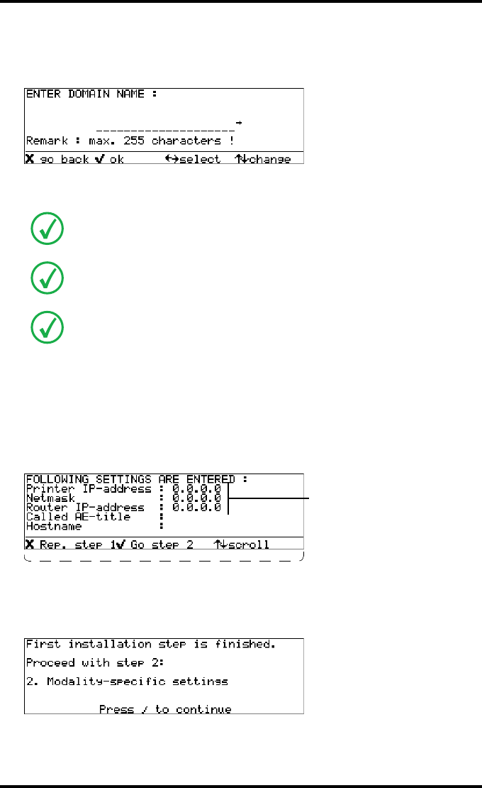
134 2900H EN 20071108Advanced operation (Key-operator mode)
DRYSTAR 5500/5503 REFERENCE MANUAL
12 Press the Confirm key to continue, or the Escape key to return to the previous
step.
The ‘Enter Domain Name’ screen is displayed:
13 Enter the Domain name by means of the arrow keys.
14 Press the Confirm key to continue, or the Escape key to return to the previous
step.
15 Press the Confirm key to continue, or the Escape key to return to the previous
step.
A screen will appear summarizing the information you have entered:
16 Press the Confirm key to go to step 2 of the installation wizard or press the
Escape key to repeat step 1.
•When you have pressed the Confirm key, the following screen will appear:
17 Press the Confirm key to continue.
Refer to ‘Data entry’ on page 33.
Make sure not to enter more than 255 characters.
Note that blank spaces will not be filled in.
DS5500
ds5500
Domain : xxxxxxx
e.g.
Prt IP-ad:123.123.123.123
Netmask:255.255.255.255
Router:123.123.123.123
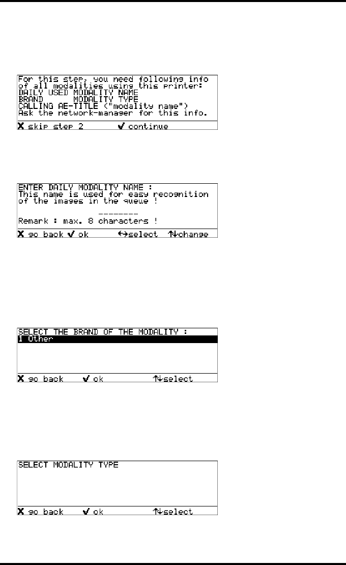
135
2900H EN 20071108 Advanced operation (Key-operator mode)
DRYSTAR 5500/5503 REFERENCE MANUAL
Entering modality-specific settings
An instruction screen shows the information you need to complete this part of
the installation:
1Press the Confirm key to continue or press the Escape key to skip this step.
•When you have pressed the Confirm key, the ‘Enter daily modality name’ screen
will appear:
2Enter the modality nickname by means of the arrow keys. Refer to ‘Data entry’
on page 33. Make sure not to enter more than 8 characters.
3Press the Confirm key to continue, or the Escape key to return to the previous
step.
The ‘Select modality brand name’ screen is displayed:
4Press the Up/Down arrow keys to select the appropriate modality brand name.
5Press the Confirm key to continue, or the Escape key to return to the previous
step.
The ‘Select modality type’ screen will be displayed:
2 Acuson
2 Philips
3 Trex
4 GE
1 MXVIEW
2 MX8000
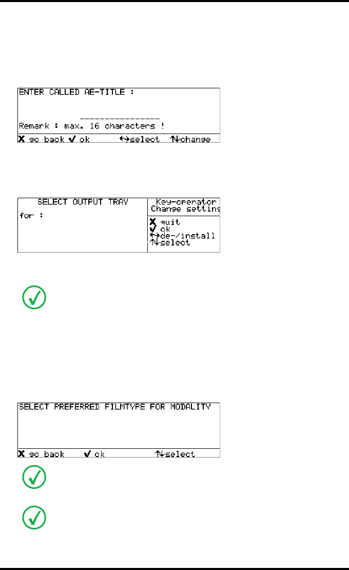
136 2900H EN 20071108Advanced operation (Key-operator mode)
DRYSTAR 5500/5503 REFERENCE MANUAL
6Press the Up/Down arrow keys to select the appropriate modality type.
7Press the Confirm key to continue, or the Escape key to return to the previous
step.
The ‘Enter Called AE-title’ screen is displayed:
8Enter the Called AE-title by means of the arrow keys. Refer to ‘Data entry’ on
page 33. Make sure not to enter more than 16 characters.
The ‘Select output tray for <daily name or AE-title>’ screen will appear:
Press the Up/Down arrow keys to navigate and (de-)install output trays with the Left/
Right arrow keys. You can install several output trays.
9Press the Confirm key to install the chosen output trays, or the Escape key to
quit the procedure without any changes.
10 Press the Confirm key to continue, or the Escape key to return to the previous
step.
The ‘Select preferred film type for modality’ screen will appear:
Each installed output tray are marked with an *.
‘DRYSTAR DT 2 Mammo’ is only shown in the list when the option for the
mammography application is activated. Refer to ‘Options and accessories’ on
page 235.
You can find the film type on the film packaging, e.g. ‘DRYSTAR DT 2 C’.
<daily name or AE-title>
* position 1 (upper)
position 2
* position 3
p
osition 4
(
lower
)
<daily name or AE-title>
DRYSTAR DT 2 B
DRYSTAR DT 2 C
DRYSTAR DT 2 Mammo
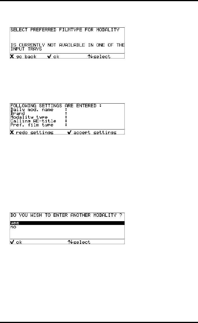
137
2900H EN 20071108 Advanced operation (Key-operator mode)
DRYSTAR 5500/5503 REFERENCE MANUAL
In case the current film type in the trays does not cover the selected film type of the
selection a message is displayed:
11 Press the Up/Down arrow keys to select the appropriate film type.
12 Press the Confirm key to continue, or the Escape key to return to the previous
step.
A screen will appear summarizing the entered information:
The following appear in the list:
•Daily modality name
•Brand
•Modality type
•Calling AE-title
•Preferred film type
13 Press the Confirm key to accept the settings, or the Escape key to redo the
settings for the current modality.
The following screen will appear, asking if you want to enter another modality:
<daily name or AE-title>
xxxxx
Philips
MXVIEW
xxxxx
DRYSTAR DT 2 B
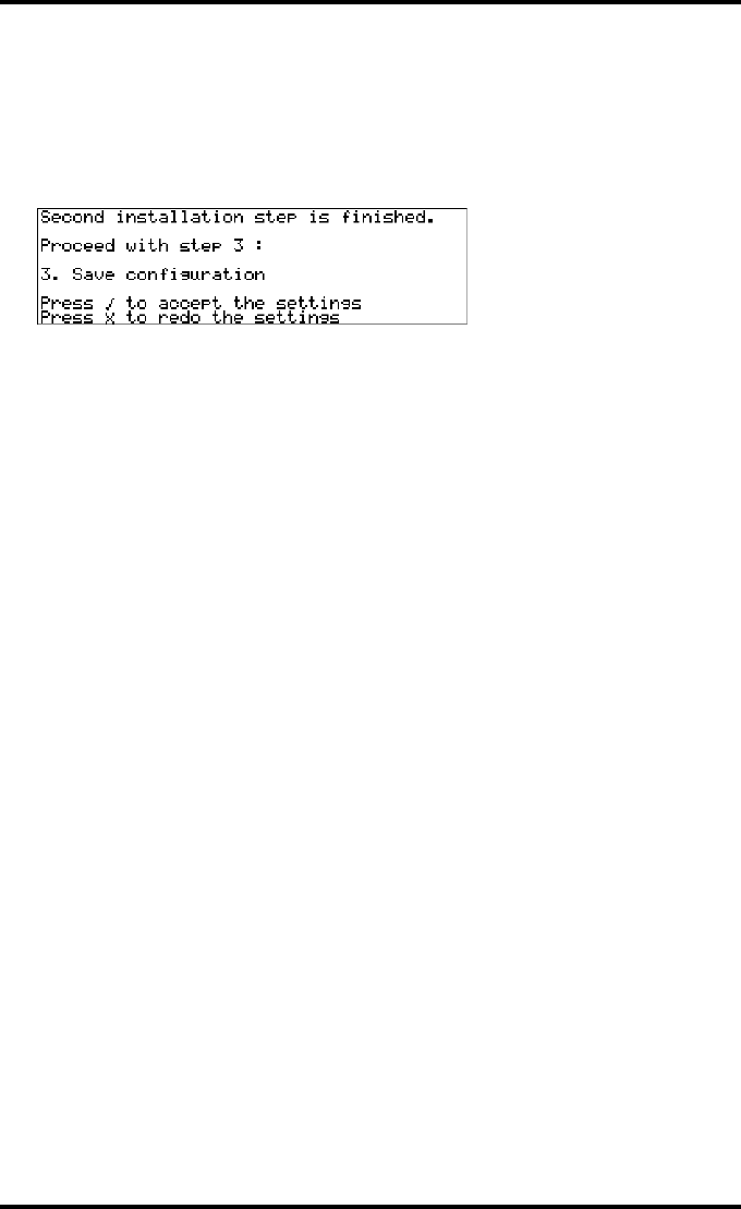
138 2900H EN 20071108Advanced operation (Key-operator mode)
DRYSTAR 5500/5503 REFERENCE MANUAL
14 Press the Up/Down arrow keys to select your choice, followed by the Confirm
key.
•If you select Yes, step 2 of the Setup wizard will be repeated for the next modality.
Go back to ‘Entering modality-specific settings’ on page 135.
•If you select No, the second step of the installation is finished. The following screen
will appear:
15 Press the Confirm key to continue.
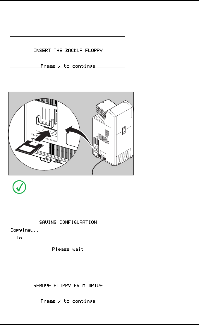
139
2900H EN 20071108 Advanced operation (Key-operator mode)
DRYSTAR 5500/5503 REFERENCE MANUAL
Saving the configuration
A screen will ask you to insert the back-up floppy:
1Insert the floppy disk.
The drive is located at the rear of the printer.
2Press the Confirm key to continue.
The ‘Saving configuration’ screen is displayed.
The printer saves the configuration on the floppy disk.
When the writing process has finished, the following screen is displayed:
For the back-up, a blank floppy disk is required (formatted, IBM-compatible,
2HD).
D:/<path><filename>
A:/<path><filename>
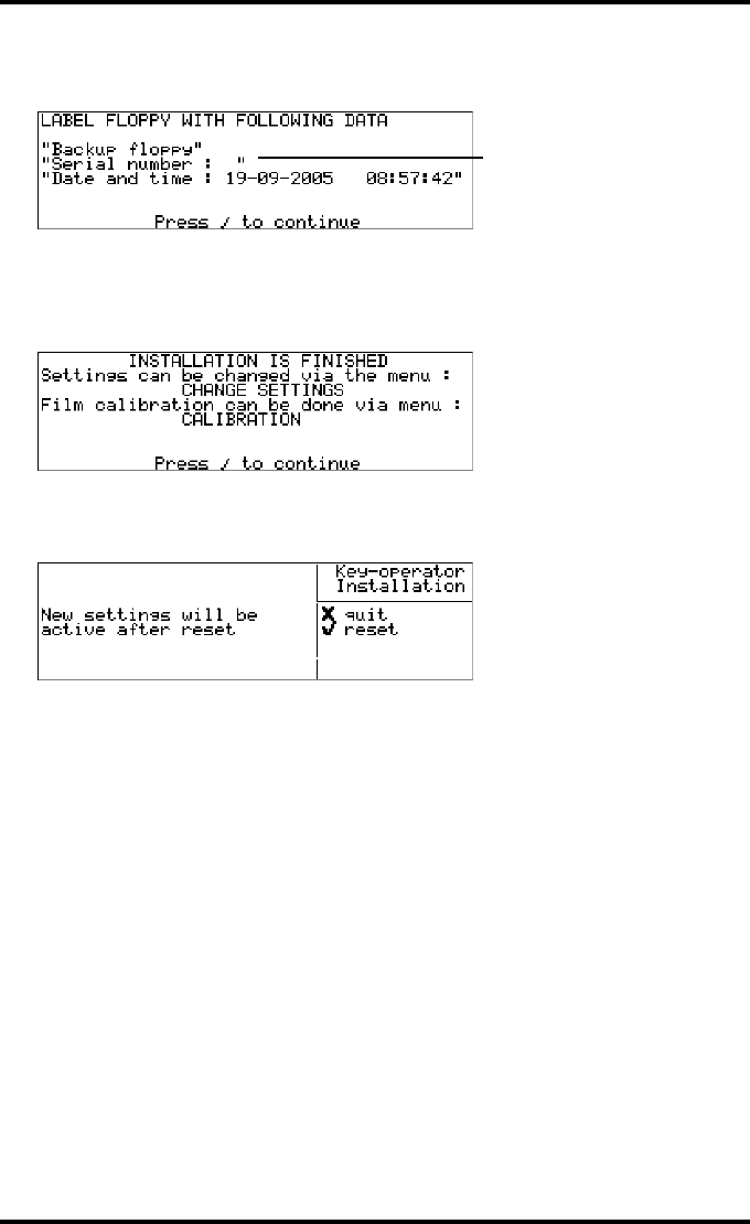
140 2900H EN 20071108Advanced operation (Key-operator mode)
DRYSTAR 5500/5503 REFERENCE MANUAL
3Remove the floppy disk and press the Confirm key.
The following screen is displayed:
4Press the Confirm key.
The installation is now finished.
The following screen is displayed:
5Press the Confirm key.
The following screen is displayed:
6Press the Escape key if you want to reboot the printer later. Press Confirm key to
reboot the printer.
The Drystar 5500 will now restart, and the new settings will be active.
e.g. 1024

141
2900H EN 20071108 Advanced operation (Key-operator mode)
DRYSTAR 5500/5503 REFERENCE MANUAL
Quality control for general radiography
applications (DT 2 B & DT 2 C)
In order to establish and maintain consistent image quality, a regular
evaluation of the image quality is advised.
The Drystar 5500 contains an automatic QC procedure for general
radiography applications and has been designed to comply with the grayscale
reproduction constancy test, according to the international standard IEC
1223-2-4. If the option for the mammography application is activated,
another QC procedure is available for the mammography application (refer to
‘Quality control for mammography application (DT 2 Mammo) (optional)’ on
page 153). This QC procedure has been designed to comply with the
Mammography Quality Standards Act (MQSA) of the FDA (refer to ‘Safety
compliance’ on page 18). In this chapter we will discuss how to control the
quality of general radiography applications.
Local Regulations may require other procedures.
The Drystar 5500 Hard Copy quality control procedures consist of two main
steps:
•Before initial use, establishing a number of reference values that will be
used for further follow-up and verifying initial image quality.
•After establishing these values, performing regular daily, weekly and
annual quality tests.
The results of these tests are recorded on Quality Control Charts.
The QC image (Refer to the ‘QC general radiography test image’ on page 146)
has several additional fields where the QC data can be filled in. This image
should be filed as part of the QC procedure.
For more information, please refer to ‘Quality Control Charts’ on page 241.
Repeat the two main steps of the Hard Copy quality procedures for each input tray
loaded with DT 2 B and/or DT 2 C films.

142 2900H EN 20071108Advanced operation (Key-operator mode)
DRYSTAR 5500/5503 REFERENCE MANUAL
Establishing the reference values and verifying image quality for
general radiography applications (DT 2 B and DT 2 C)
After installation of a new Drystar 5500 and before initial use you must
establish Quality Control aim values. These values will be used as the base
line for comparison when daily Quality Control is done. These values should
be determined again after major service, repair or software update.
The following Quality Control aim values must be determined:
•The daily operating density levels. Refer to ‘Establishing the daily operating
reference density levels for general radiography applications (DT 2 B and
DT 2 C)’ on page 143.
•Drystar 5500 image geometry. Refer to ‘Establishing the image geometry
reference values for general radiography applications (DT 2 B and DT 2 C)’ on
page 146.
Once Quality Control aim values are established you must evaluate the
Spatial Resolution, the Artifact Levels and the Low Contrast Visibility to
determine if the image quality is acceptable. Refer to ‘Verifying Acceptable
Spatial Resolution, Artifact Levels and Low Contrast Visibility for general
radiography applications (DT 2 B and DT 2 C)’ on page 148.
The Quality Control aim values, the Spatial Resolution and Artifact Levels and
the Image Geometry values are all recorded on the Quality Control charts.
Refer to ‘Charts for general radiography QC’ on page 242.
On these charts, the following test conditions are also recorded:
•The type and serial number of the Drystar 5500.
•The type and emulsion number of the film used to determine the reference
values.
•The type of densitometer used.
•The time (day, month, year) that the values were established.
Before you can establish the daily operating levels, the Drystar 5500 must
be switched on for at least 15 minutes and it must be calibrated as well.
Refer to ‘Switching on the Drystar 5500’ on page 34 and ‘Performing the
calibration procedures’ on page 111.
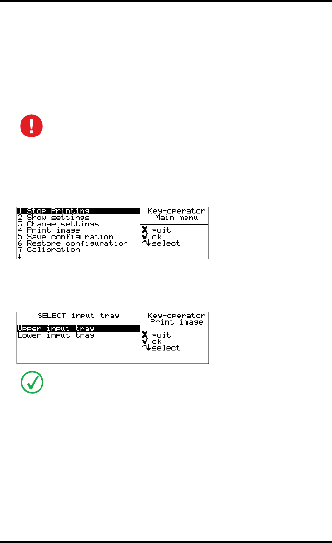
143
2900H EN 20071108 Advanced operation (Key-operator mode)
DRYSTAR 5500/5503 REFERENCE MANUAL
Establishing the daily operating reference density levels for general radiog-
raphy applications (DT 2 B and DT 2 C)
This procedure enables you to establish the base line values for:
•Low density
•Mid density
•High density
To establish the daily operating levels, proceed as follows:
1Press the Key-operator key to enter the Key-operator mode.
The ‘Key-operator main menu’ screen appears:
2Press the Down key eight times, followed by the Confirm key to select ‘Quality
Control’
The ‘Select input tray’ screen appears:
3Press the Up/Down arrow keys to select the proper input tray, followed by the
Confirm key.
The Drystar 5500 will automatically print the QC general radiography test image.
The densitometer of the Drystar 5500 is calibrated at installation.
Authorized service personnel should recalibrate the densitometer
annually or after major service or repair.
When controlling the Drystar 5500 via a remote PC, The ‘Select input tray’ screen is
preceded by a screen, which allows you to:
• Start the quality control procedure immediately,
• Edit additional data for the last quality control measuring.
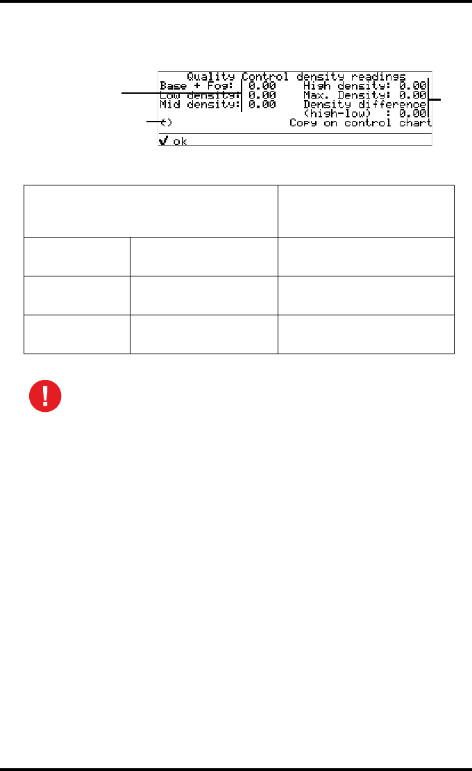
144 2900H EN 20071108Advanced operation (Key-operator mode)
DRYSTAR 5500/5503 REFERENCE MANUAL
4After the image is printed, the system will display all measured optical density
values:
The displayed values (that have to be monitored) represent the following steps on the
test film:
5Record the density levels on Chart 1 (‘Drystar 5500/5503: Determination of
Operating Levels’). Refer to ‘Charts for general radiography QC’ on page 242.
6Press the Confirm key to return to the main menu.
7Repeat steps 1 through 6 once a day for five consecutive days, as indicated on
the Drystar 5500 Chart 1.
8Calculate the average value of the densities from the five images. These values
represent operating levels or aim values, for each density.
Operating Level
Value (Macbeth units)
(according IEC 1223-2-4
or better)
Low density the density value of the
Low density step 0.4 ± 0.05
Mid density the density value of the
Mid density step 1.2 ± 0.15
High density the density value of the
High density step 2.0 ± 0.20
If the mid density value does not meet or exceeds the recommended
values, the cause must be found and the problem solved before any further
clinical films can be printed.
Refer to ‘Maintaining image quality and resolving Image quality problems’ on
page 220 and ‘Preventive maintenance schedule’ on page 186, or call your
local Agfa service organization.
Default densitometer
e.g. Macbeth TR924
0.19
0.36
1.14
1.92
3.60
1.56

145
2900H EN 20071108 Advanced operation (Key-operator mode)
DRYSTAR 5500/5503 REFERENCE MANUAL
9Record the respective aim (average) values as the ‘Operating levels’ on Charts
2a and 2b (‘Drystar 5500/5503 Daily Density Control Chart’). Refer to ‘Charts
for general radiography QC’ on page 242.
The calculated ‘Operating levels’ should be as follows:
10 These charts will be used for the daily quality test. For more information, refer
to ‘Performing the daily QC test for general radiography applications (DT 2 B and
DT 2 C)’ on page 149.
Operating Level Value (Macbeth units)
(according IEC 1223-2-4 or better)
Low density 0.4 ± 0.05
Mid density 1.2 ± 0.15
High density 2.0 ± 0.20
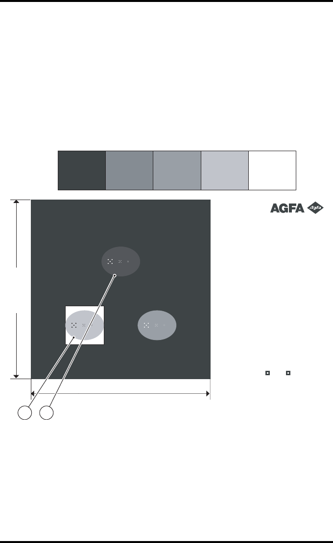
146 2900H EN 20071108Advanced operation (Key-operator mode)
DRYSTAR 5500/5503 REFERENCE MANUAL
Establishing the image geometry reference values for general radiography
applications (DT 2 B and DT 2 C)
To establish the image geometry reference values, proceed as follows:
1Print the QC general radiography test image or use the previously printed test
image.
You should obtain an image looking like this (without the dimensions A and B):
QC general radiography test image
LowLow Base + FogBase + Fog
Max (100%)Max (100%)
HighHigh MidMid
IdentificationIdentificationIdentificationIdentification
Initials: __________Initials: __________Initials: __________Initials: __________
Base + Fog: ______________Base + Fog: ______________Base + Fog: ______________Base + Fog: ______________
Low Density: _____________Low Density: _____________Low Density: _____________Low Density: _____________
Mid Density: _____________Mid Density: _____________Mid Density: _____________Mid Density: _____________
High Density: ____________High Density: ____________High Density: ____________High Density: ____________
Max Density: _____________Max Density: _____________Max Density: _____________Max Density: _____________
Density
Difference (High - Low): ___________
Density
Difference (High - Low): ___________
Density
Difference (High - Low): ___________
Density
Difference (High - Low): ___________
Date: __________Date: __________Date: __________Date: __________
Time: _________
_
Time: _________
_
Time: _________
_
Time: _________
_
Daily density testsDaily density testsDaily density testsDaily density tests
Weekly spatial resolution tes
t
Weekly spatial resolution tes
t
Weekly spatial resolution tes
t
Weekly spatial resolution tes
t
Quality Control Test ImageQuality Control Test Image
(Version 3
)
Sets of dots visible? Yes NoSets of dots visible? Yes NoSets of dots visible? Yes NoSets of dots visible? Yes No
Dimension B
Dimension A
1 2

147
2900H EN 20071108 Advanced operation (Key-operator mode)
DRYSTAR 5500/5503 REFERENCE MANUAL
2To determine the reference values for geometry, measure the distances A and B
of the geometric square on the test image.
3Record these values as reference dimensions Aref and Bref on Chart 4
(‘Drystar 5500/5503 Geometric Consistency Control Chart’). Refer to ‘Charts
for general radiography QC’ on page 242.
These charts will be used for the annual quality test. For more information, refer to
‘Performing the Annual QC tests for general radiography applications (DT 2 B and
DT 2 C)’ on page 152.
4Save this film for future reference.
Make sure to measure distance A from the left edge of the left line to the
right edge of the right line and distance B from the upper edge of the
upper line to the lower edge of the lower line.
We strongly recommend using a 30 cm (12 inch) machinist scale with
0.5 mm divisions (1/64 inch).

148 2900H EN 20071108Advanced operation (Key-operator mode)
DRYSTAR 5500/5503 REFERENCE MANUAL
Verifying Acceptable Spatial Resolution, Artifact Levels and Low Contrast
Visibility for general radiography applications (DT 2 B and DT 2 C)
To verify acceptable spatial resolution, artifact levels and low contrast
visibility, proceed as follows:
1Print the QC general radiography test image or use the previously printed QC
general radiography test image used to establish the daily operating density
levels.
2Visually check the QC general radiography test image for artifacts: no
significant disturbing artifacts should be visible.
3Check the spatial resolution in each of the three ovals. Within each oval there
are three groups, each having five dots. All five dots of each group must be
visible with a magnifying glass. The smallest cluster of 5 dots is only visible if
the viewing conditions are good.
4Check the Low Contrast Visibility at both the high (100 / 95%) and low end
(0 / 5%) of the density scale. You should be able to see the circle in the square
(refer to item 1 on the ‘QC general radiography test image’ on page 146) and the
upper circle (refer to item 2 on the ‘QC general radiography test image’ on
page 146).
5Record these values at the top of Chart 3 (‘Drystar 5500/5503 Artifacts and
Spatial Resolution Control Chart’). Refer to ‘Charts for general radiography QC’
on page 242.
6These charts will be used for the weekly quality test. For more information,
refer to ‘Performing the Weekly QC tests for general radiography applications
(DT 2 B and DT 2 C)’ on page 151.
Good viewing conditions are important for the correct interpretation of
both diagnostic and test images. Make sure that the light box intensity
(luminance) is between 2000 and 4000 cd/m² (4500 and 6500 °K) for
general radiography. Use a magnifying glass and use shutters to collimate.
Make sure the ambient light is low.
In case of significant artifacts or insufficient spatial resolution, the cause
must be found and the problem solved before any further clinical films can
be printed.
Refer to ‘Maintaining image quality and resolving Image quality problems’ on
page 220 and ‘Preventive maintenance schedule’ on page 186, or call your
local Agfa service organization.
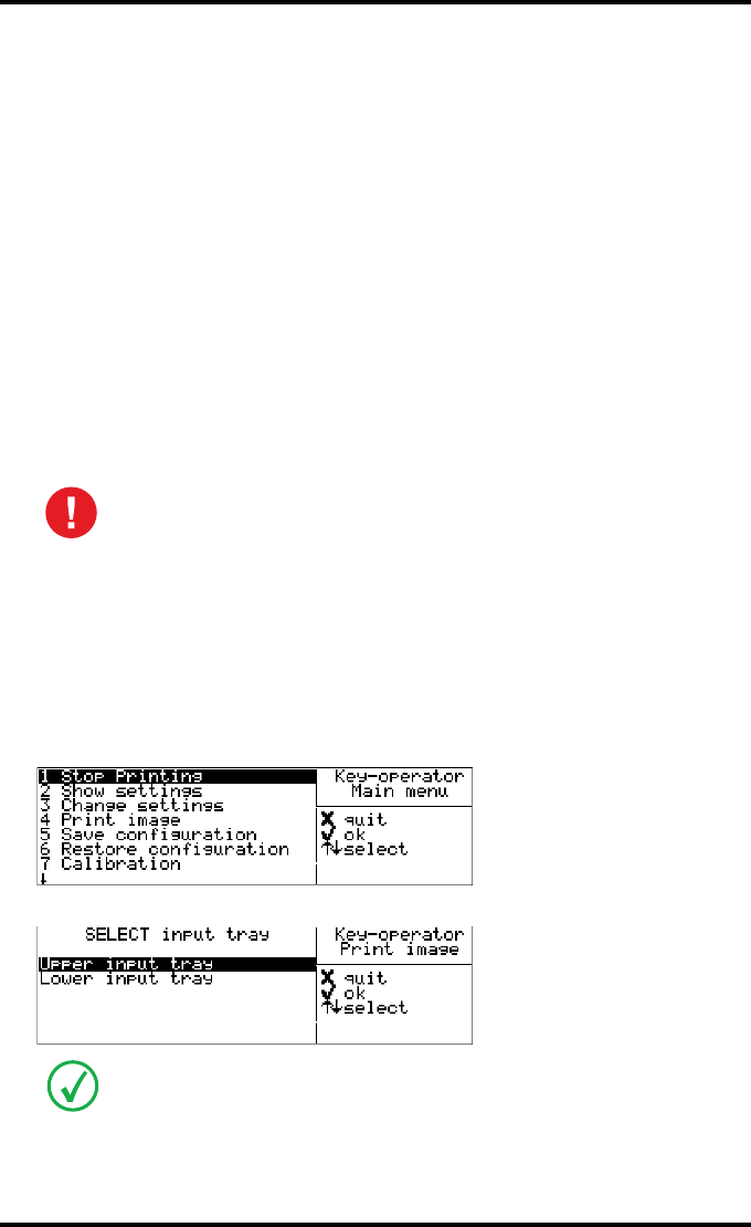
149
2900H EN 20071108 Advanced operation (Key-operator mode)
DRYSTAR 5500/5503 REFERENCE MANUAL
Performing quality control (QC) tests for general radiography
applications (DT 2 B and DT 2 C)
The following procedures must be performed daily, weekly or annually as
indicated. When used in a mobile application it is required to perform QC
after every move.
The reason for performing quality control tests is to determine if any
significant image quality variation or deterioration has occurred which may
require corrective action. Comparing the results of the tests with the reference
values previously established does this.
This procedure allows the operator to take the necessary preventive actions
before any image quality loss can take place.
Performing the daily QC test
for general radiography applications (DT 2 B
and DT 2 C)
1Turn on the Drystar 5500 and wait at least for 15 minutes. Refer to ‘Switching on
the Drystar 5500’ on page 34.
2Press the Key-operator key to enter the Key-operator mode.
3Press the Down key eight times, followed by the Confirm key to select ‘Quality
Control’.
The ‘Select input tray’ screen appears:
This test must be performed every day before any clinical film can be
processed.
When controlling the Drystar 5500 via a remote PC, The ‘Select input tray’ screen is
preceded by a screen, which allows you to:
• Start the quality control procedure immediately,
• Edit additional data for the last quality control measuring.
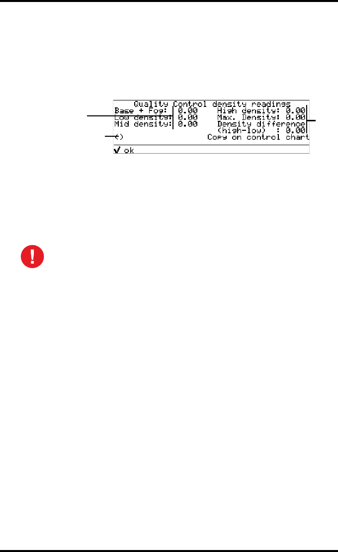
150 2900H EN 20071108Advanced operation (Key-operator mode)
DRYSTAR 5500/5503 REFERENCE MANUAL
4Press the Up/Down arrow keys to select the proper input tray, followed by the
Confirm key.
The Drystar 5500 will automatically print the QC general radiography test image.
5After the image is printed, the system will display all measured optical density
values:
6Record the low, mid and high density values on Charts 2A and 2B
(‘Drystar 5500/5503 Daily Density Control Chart’). Also record the date and
time of the test on the charts and on the QC general radiography test images.
Refer to ‘Charts for general radiography QC’ on page 242.
7Press the Confirm key to return to the main menu.
In case the measure results are not within the aim values, the reason for
the unacceptable density variations must be identified and resolved before
any further clinical films can be processed. This may include repeating the
film calibration procedure.
For possible causes of non-compliance and the respective actions, refer to
‘Maintaining image quality and resolving Image quality problems’ on page 220
and ‘Preventive maintenance schedule’ on page 186.
Default densitometer
e.g. Macbeth TR924
0.19
0.36
1.14
1.92
3.60
1.56

151
2900H EN 20071108 Advanced operation (Key-operator mode)
DRYSTAR 5500/5503 REFERENCE MANUAL
Performing the Weekly QC tests for general radiography applications
(DT 2 B and DT 2 C)
Spatial Resolution, Artifact Test and Low Contrast Visibility
To identify artifacts and verify spatial resolution you must perform the
following test weekly or as needed for troubleshooting image quality
problems.
1First, print out the QC general radiography test image. Refer to ‘Performing the
daily QC test for general radiography applications (DT 2 B and DT 2 C)’ on
page 149.
2Check the QC general radiography test image visually for artifacts: no
significant disturbing artifacts should be visible.
3Check the spatial resolution.
The test film also shows three squares which each contains an oval. These 3 ovals
contain 3 groups, each having 5 dots. All five dots of each group must be visible with a
magnifying glass. The smallest cluster of 5 dots is only visible if the viewing conditions
are good.
4Check the Low Contrast Visibility at both the high (100 / 95%) and low end
(0 / 5%) of the density scale. You should be able to see the circle in the square
(refer to item 1 on the ‘QC general radiography test image’ on page 146) and the
upper circle (refer to item 2 on the ‘QC general radiography test image’ on
page 146).
5Record these values on Chart 3 (‘Drystar 5500/5503 Artifacts and Spatial
Resolution Control Chart’). Refer to ‘Charts for general radiography QC’ on
page 242.
Good viewing conditions are important for the correct interpretation of
both diagnostic and test images. Make sure that the light box intensity
(luminance) is between 2000 and 4000 cd/m² (4500 and 6500 °K) for
general radiography. Use a magnifying glass and use shutters to collimate.
Make sure the ambient light is low.
In case of significant artifacts, insufficient spatial resolution or failure of
any other recommended QC tests, the cause of the problem must be
identified, and corrective action must be taken before the Drystar 5500
can be used for any further clinical imaging.
Refer to ‘Maintaining image quality and resolving Image quality problems’ on
page 220 and ‘Preventive maintenance schedule’ on page 186, or call your
local Agfa service organization for assistance.

152 2900H EN 20071108Advanced operation (Key-operator mode)
DRYSTAR 5500/5503 REFERENCE MANUAL
Performing the Annual QC tests for general radiography applications
(DT 2 B and DT 2 C)
Geometric Consistency Test
To be able to notice fluctuations in image size and aspect ratio, you must
perform this procedure once a year.
1First, perform the daily test.
2Measure the distances A and B of the geometric square on the QC general
radiography test image. Refer to ‘Establishing the image geometry reference
values for general radiography applications (DT 2 B and DT 2 C)’ on page 146.
3Record these values as measured distances A and B on Chart 4 (‘Drystar 5500/
5503 Geometric Consistency Control Chart’). Refer to ‘Charts for general
radiography QC’ on page 242.
4Compare the measured A and B dimensions with the reference dimension
values, Aref and Bref on Chart 4 (‘Drystar 5500/5503 Geometric Consistency
Control Chart’). Refer to ‘Charts for general radiography QC’ on page 242.
The differences between the measured dimensions of A and B and the reference
values Aref and Bref should be less than or equal to 1.0%.
5Check for image distortion.
6Calculate the aspect ratio by dividing A by B.
The result must be 1 +/- 0.01
Make sure to measure distance A from the left edge of the left line to the
right edge of the right line and distance B from the upper edge of the
upper line to the lower edge of the lower line.
We strongly recommend using a 30 cm (12 inch) machinist scale with
0.5 mm divisions (1/64 inch).
If the image size or distortion values exceed the limits, contact Agfa
service to resolve the problem.

153
2900H EN 20071108 Advanced operation (Key-operator mode)
DRYSTAR 5500/5503 REFERENCE MANUAL
Quality control for mammography application
(DT 2 Mammo) (optional)
In order to establish and maintain consistent image quality, a regular
evaluation of the image quality is advised.
The Drystar 5500 contains an automatic QC procedure for general
radiography applications (refer to ‘Quality control for general radiography
applications (DT 2 B & DT 2 C)’ on page 141) and has been designed to comply
with the grayscale reproduction constancy test, according to the international
standard IEC 1223-2-4. If the option for the mammography application is
activated, another QC procedure is available for the mammography
application. This QC procedure has been designed to comply with the
Mammography Quality Standards Act (MQSA) of the FDA (refer to ‘Safety
compliance’ on page 18). In this chapter we will discuss how to control the
quality of general radiography applications.
Local Regulations may require other procedures.
The Drystar 5500 Hard Copy quality control procedures consist of two main
steps:
•Before initial use, establishing a number of reference values that will be
used for further follow-up and verifying initial image quality.
•After establishing these values, performing regular daily, weekly and
annual quality tests.
The results of these tests are recorded on Quality Control Charts.
The QC image (Refer to the ‘QC mammography test image’ on page 158) has
several additional fields where the QC data can be filled in. This image should
be filed as part of the QC procedure.
For more information, please refer to ‘Quality Control Charts’ on page 241.
Repeat the two main steps of the Hard Copy quality procedures for each input tray
loaded with DT 2 Mammo films.

154 2900H EN 20071108Advanced operation (Key-operator mode)
DRYSTAR 5500/5503 REFERENCE MANUAL
Establishing the reference values and verifying image quality for
mammography application (DT 2 Mammo) (optional)
After installation of a new Drystar 5500 and before initial use you must
establish Quality Control aim values. These values will be used as the base
line for comparison when daily Quality Control is done. These values should
be determined again after major service, repair or software update.
The following Quality Control aim values must be determined:
•The daily operating density levels. Refer to ‘Establishing the daily operating
reference density levels for mammography application (DT 2 Mammo)
(optional)’ on page 155.
•Drystar 5500 image geometry. Refer to ‘Establishing the image geometry
reference values for mammography application (DT 2 Mammo) (optional)’
on page 158.
Once Quality Control aim values are established you must evaluate the
Spatial Resolution, the Artifact Levels and the Low Contrast Visibility to
determine if the image quality is acceptable. Refer to ‘Verifying Acceptable
Spatial Resolution and Artifact Levels and Low Contrast Visibility for mammography
application (DT 2 Mammo) (optional)’ on page 160.
The Quality Control aim values, the Spatial Resolution and Artifact Levels and
the Image Geometry values are all recorded on the Quality Control charts.
Refer to ‘Charts for mammography QC (optional)’ on page 247.
On these charts, the following test conditions are also recorded:
•The type and serial number of the Drystar 5500.
•The type and emulsion number of the film used to determine the reference
values.
•The type of densitometer used.
•The time (day, month, year) that the values were established.
Before you can establish the daily operating levels, the Drystar 5500 must
be switched on for at least 15 minutes and it must be calibrated as well.
Refer to ‘Switching on the Drystar 5500’ on page 34 and ‘Performing the
calibration procedures’ on page 111.
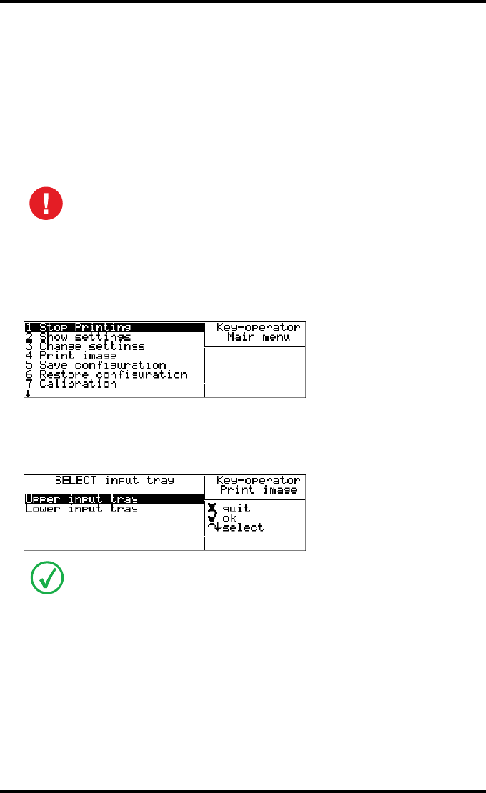
155
2900H EN 20071108 Advanced operation (Key-operator mode)
DRYSTAR 5500/5503 REFERENCE MANUAL
Establishing the daily operating reference density levels for mammography
application (DT 2 Mammo) (optional)
This procedure enables you to establish the base line values for:
•Base + Fog density
•Low density
•Mid density
•High density
To establish the daily operating levels, proceed as follows:
1Press the Key-operator key to enter the Key-operator mode.
The ‘Key-operator main menu’ screen appears:
2Press the Down key eight times, followed by the Confirm key to select ‘Quality
Control’.
The ‘Select input tray’ screen appears:
3Press the Up/Down arrow keys to select the proper input tray, followed by the
Confirm key.
The Drystar 5500 will automatically print the QC mammography test image.
The densitometer of the Drystar 5500 is calibrated at installation.
Authorized service personnel should recalibrate the internal densitometer
annually or after major service or repair.
When controlling the Drystar 5500 via a remote PC, The ‘Select input tray’ screen is
preceded by a screen, which allows you to:
• Start the quality control procedure immediately,
• Edit additional data for the last quality control measuring.
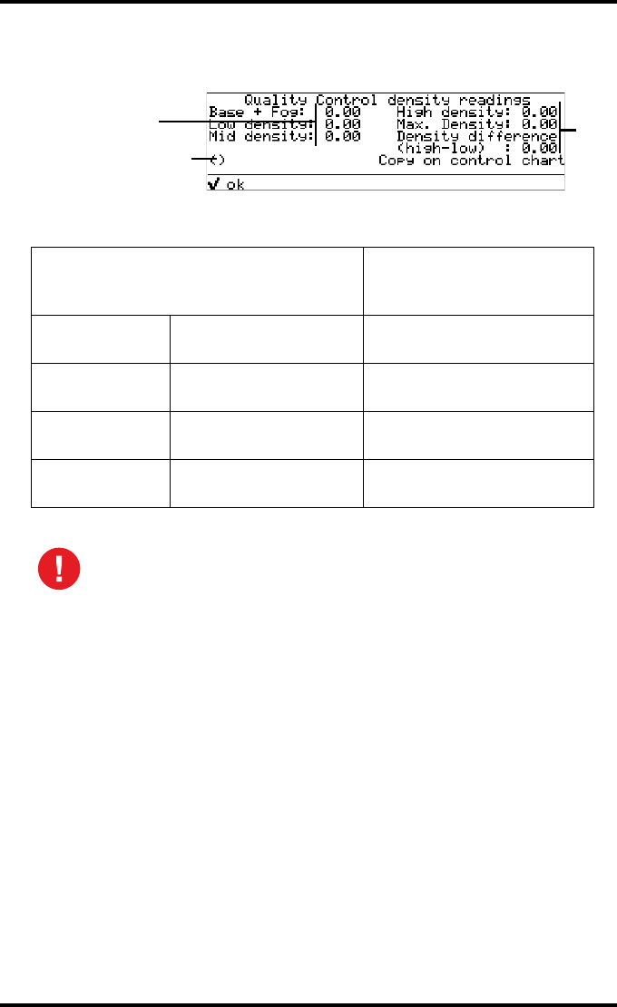
156 2900H EN 20071108Advanced operation (Key-operator mode)
DRYSTAR 5500/5503 REFERENCE MANUAL
4After the image is printed, the system will display all measured optical density
values:
The displayed values (that have to be monitored) represent the following steps on the
test film:
5Record the density levels on Chart 1 (‘Drystar 5500/5503: Determination of
Operating Levels’). Refer to ‘Charts for mammography QC (optional)’ on
page 247.
6Press the Confirm key to return to the main menu.
7Repeat steps 1 through 6 once a day for five consecutive days, as indicated on
the Drystar 5500 Chart 1.
8Calculate the average value of the densities from the five images. These values
represent operating levels or aim values, for each density.
Operating Level
Value (Macbeth units)
(according to NEMA
standards XR 23-2006)
Base + Fog the density value of the
Base + Fog step 0.22 ± 0.03
Low density the density value of the
low density step 0.52 ± 0.07
Mid density the density value of the
mid density step 1.35 ± 0.15
High density the density value of the
high density step 2.35 ± 0.15
If the mid density value does not meet or exceeds the recommended
values, the cause must be found and the problem solved before any further
clinical films can be printed.
Refer to ‘Maintaining image quality and resolving Image quality problems’ on
page 220 and ‘Preventive maintenance schedule’ on page 186, or call your
local Agfa service organization.
Default densitometer
e.g. Macbeth TR924
0.19
0.50
1.30
2.23
3.60
1.73

157
2900H EN 20071108 Advanced operation (Key-operator mode)
DRYSTAR 5500/5503 REFERENCE MANUAL
9Record the respective aim (average) values as the ‘Operating levels’ on Charts
2a and 2b (‘Drystar 5500/5503 Daily Density Control Chart’). Refer to ‘Charts
for mammography QC (optional)’ on page 247.
The calculated ‘Operating levels’ should be as follows:
10 These charts will be used for the daily quality test. For more information, refer
to ‘Performing the daily QC test for mammography application (DT 2 Mammo)
(optional)’ on page 161.
Operating Level Value (Macbeth units)
(according to NEMA standards XR 23-2006)
Base + Fog 0.22 ± 0.03
Low density 0.52 ± 0.07
Mid density 1.35 ± 0.15
High density 2.35 ± 0.15
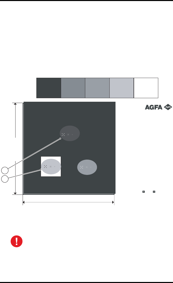
158 2900H EN 20071108Advanced operation (Key-operator mode)
DRYSTAR 5500/5503 REFERENCE MANUAL
Establishing the image geometry reference values for mammography appli-
cation (DT 2 Mammo) (optional)
To establish the image geometry reference values, proceed as follows:
1Print the QC mammography test image or use the previously printed test image.
You should obtain an image looking like this (without the dimensions A and B):
QC mammography test image
2To determine the reference values for geometry, measure the distances A and B
of the geometric square on the test image.
Make sure to measure distance A from the left edge of the left line to the
right edge of the right line and distance B from the upper edge of the
upper line to the lower edge of the lower line.
We strongly recommend using a 30 cm (12-inch) machinist scale with 0.5
mm divisions (1/64 inch).
LowLow Base + FogBase + Fog
Max (100%)Max (100%)
HighHigh MidMid
IdentificationIdentificationIdentificationIdentification
Initials: __________Initials: __________Initials: __________Initials: __________
Base + Fog: ______________Base + Fog: ______________Base + Fog: ______________Base + Fog: ______________
Low Density: _____________Low Density: _____________Low Density: _____________Low Density: _____________
Mid Density: _____________Mid Density: _____________Mid Density: _____________Mid Density: _____________
High Density: ____________High Density: ____________High Density: ____________High Density: ____________
Max Density: _____________Max Density: _____________Max Density: _____________Max Density: _____________
Density
Difference (High - Low): ___________
Density
Difference (High - Low): ___________
Density
Difference (High - Low): ___________
Density
Difference (High - Low): ___________
Date: __________Date: __________Date: __________Date: __________
Time: _________
_
Time: _________
_
Time: _________
_
Time: _________
_
Daily density testsDaily density testsDaily density testsDaily density tests
Weekly spatial resolution tes
t
Weekly spatial resolution tes
t
Weekly spatial resolution tes
t
Weekly spatial resolution tes
t
Quality Control Test Image - Mammo version
(Version 4
)
Sets of dots visible? Yes NoSets of dots visible? Yes NoSets of dots visible? Yes NoSets of dots visible? Yes No
Dimension B
Dimension A
1
2

159
2900H EN 20071108 Advanced operation (Key-operator mode)
DRYSTAR 5500/5503 REFERENCE MANUAL
3Record these values as reference dimensions Aref and Bref on Chart 4
(‘Drystar 5500/5503 Geometric Consistency Control Chart’). Refer to ‘Charts
for mammography QC (optional)’ on page 247.
These charts will be used for the annual quality test. For more information, refer to
‘Performing the Annual QC tests for mammography application (DT 2 Mammo)
(optional)’ on page 164.
4Save this film for future reference.

160 2900H EN 20071108Advanced operation (Key-operator mode)
DRYSTAR 5500/5503 REFERENCE MANUAL
Verifying Acceptable Spatial Resolution and Artifact Levels and Low Con-
trast Visibility for mammography application (DT 2 Mammo) (optional)
To verify acceptable spatial resolution, artifact levels and low contrast
visibility, proceed as follows:
1Print the QC mammography test image or use the previously printed QC
mammography test image used to establish the daily operating density levels.
2Visually check the test image for artifacts: no significant disturbing artifacts
should be visible.
3Check the spatial resolution in each of the three ovals. Within each oval there
are three groups, each having five dots. All five dots of each group must be
visible with a magnifying glass. The smallest cluster of 5 dots is only visible if
the viewing conditions are good.
4Check the Low Contrast Visibility at both the high (100 / 95%) and low end
(0 / 5%) of the density scale. You should be able to see the circle in the square
(refer to item 1 on the ‘QC mammography test image’ on page 158) and the
upper circle (refer to item 2 on the ‘QC mammography test image’ on page 158).
5Record these values at the top of Chart 3 (‘Drystar 5500/5503 Artifacts and
Spatial Resolution Control Chart’). Refer to ‘Charts for mammography QC
(optional)’ on page 247.
6These charts will be used for the weekly quality test. For more information,
refer to ‘Performing the Weekly QC tests for mammography application
(DT 2 Mammo) (optional)’ on page 163.
Good viewing conditions are important for the correct interpretation of
both diagnostic and test images. Make sure that the light box intensity
(luminance) is between 3000 and 6000 cd/m² (4500 and 6500 °K) for
mammography. Use a magnifying glass and use shutters to collimate.
Make sure the ambient light is low.
In case of significant artifacts or insufficient spatial resolution, the cause
must be found and the problem solved before any further clinical films can
be printed.
Refer to ‘Maintaining image quality and resolving Image quality problems’ on
page 220 and ‘Preventive maintenance schedule’ on page 186, or call your
local Agfa service organization.
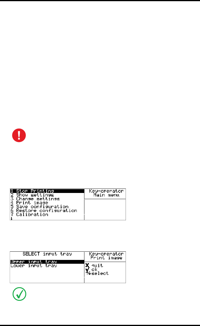
161
2900H EN 20071108 Advanced operation (Key-operator mode)
DRYSTAR 5500/5503 REFERENCE MANUAL
Performing quality control (QC) tests for mammography
application (DT 2 Mammo) (optional)
The following procedures must be performed daily, weekly or annually as
indicated. When used in a mobile application it is required to perform QC
after every move.
The reason for performing quality control tests is to determine if any
significant image quality variation or deterioration has occurred which may
require corrective action. Comparing the results of the tests with the reference
values previously established does this.
This procedure allows the operator to take the necessary preventive actions
before any image quality loss can take place.
Performing the daily QC test for mammography application
(DT 2 Mammo) (optional)
1Turn on the Drystar 5500 and wait at least for 15 minutes. Refer to ‘Switching on
the Drystar 5500’ on page 34.
2Press the Key-operator key to enter the Key-operator mode.
The ‘Key-operator main menu’ screen appears:
3Press the Down key eight times, followed by the Confirm key to select ‘Quality
Control’.
The ‘Select input tray’ screen appears:
This test must be performed every day before any clinical film can be
processed.
When controlling the Drystar 5500 via a remote PC, The ‘Select input tray’ screen is
preceded by a screen, which allows you to:
• Start the quality control procedure immediately,
• Edit additional data for the last quality control measuring.
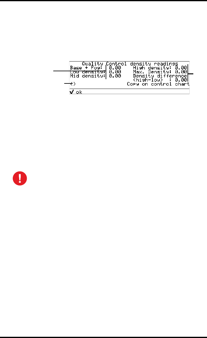
162 2900H EN 20071108Advanced operation (Key-operator mode)
DRYSTAR 5500/5503 REFERENCE MANUAL
4Press the Up/Down arrow keys to select the proper input tray, followed by the
Confirm key.
The Drystar 5500 will automatically print the QC mammography test image.
5After the image is printed, the system will display all measured optical density
values:
6Record the Base + Fog, the Mid density, the Maximum density and the Density
Difference values on Charts 2A and 2B (‘Drystar 5500/5503 Daily Density
Control Chart’). Also record the date and time of the test on the charts and on
the QC mammography test images. Refer to ‘Charts for mammography QC
(optional)’ on page 247.
7Press the Confirm key to return to the main menu.
8Press the ok key to return to the main menu.
In case the measure results are not within the aim values, the reason for
the unacceptable density variations must be identified and resolved before
any further clinical films can be processed. This may include repeating the
film calibration procedure.
For possible causes of non-compliance and the respective actions, refer to
‘Maintaining image quality and resolving Image quality problems’ on page 220
and ‘Preventive maintenance schedule’ on page 186.
Default densitometer
e.g. Macbeth TR924
0.19
0.30
1.30
2.12
3.60
1.82

163
2900H EN 20071108 Advanced operation (Key-operator mode)
DRYSTAR 5500/5503 REFERENCE MANUAL
Performing the Weekly QC tests for mammography application
(DT 2 Mammo) (optional)
Spatial Resolution, Artifact Test and Low Contrast Visibility
To identify artifacts and verify spatial resolution you must perform the
following test weekly or as needed for troubleshooting image quality
problems.
1First, print out the QC mammography test image. Refer to ‘Performing the daily
QC test for mammography application (DT 2 Mammo) (optional)’ on page 161.
2Check the test image visually for artifacts: no significant disturbing artifacts
should be visible.
3Check the spatial resolution.
The test film also shows three squares which each contains an oval. These 3 ovals
contain 3 groups, each having 5 dots. All five dots of each group must be visible with a
magnifying glass. The smallest cluster of 5 dots is only visible if the viewing conditions
are good.
4Check the Low Contrast Visibility at both the high (100 / 95%) and low end
(0 / 5%) of the density scale. You should be able to see the circle in the square
(refer to item 1 on the ‘QC mammography test image’ on page 158) and the
upper circle (refer to item 2 on the ‘QC mammography test image’ on page 158).
5Record these values on Chart 3 (‘Drystar 5500/5503 Artifacts and Spatial
Resolution Control Chart’). Refer to ‘Charts for mammography QC (optional)’
on page 247.
Good viewing conditions are important for the correct interpretation of
both diagnostic and test images. Make sure that the light box intensity
(luminance) is 3000 and 6000 cd/m² (4500 and 6500 °K) for
mammography. Use a magnifying glass and use shutters to collimate.
Make sure the ambient light is low.
In case of significant artifacts, insufficient spatial resolution or failure of
any other recommended QC tests, the cause of the problem must be
identified, and corrective action must be taken before the Drystar 5500
can be used for any further clinical imaging.
Refer to ‘Maintaining image quality and resolving Image quality problems’ on
page 220 and ‘Preventive maintenance schedule’ on page 186 or call your local
Agfa service organization for assistance.

164 2900H EN 20071108Advanced operation (Key-operator mode)
DRYSTAR 5500/5503 REFERENCE MANUAL
Performing the Annual QC tests for mammography application
(DT 2 Mammo) (optional)
Geometric Consistency Test
To be able to notice fluctuations in image size and aspect ratio, you must
perform this procedure once a year.
1First, perform the daily test.
2Measure the distances A and B of the geometric square on the QC
mammography test image. Refer to ‘Establishing the image geometry reference
values for mammography application (DT 2 Mammo) (optional)’ on page 158.
3Record these values as measured distances A and B on Chart 4 (‘Drystar 5500/
5503 Geometric Consistency Control Chart’). Refer to ‘Charts for
mammography QC (optional)’ on page 247.
4Compare the measured A and B dimensions with the reference dimension
values, Aref and Bref on Chart 4 (‘Drystar 5500/5503 Geometric Consistency
Control Chart’). Refer to ‘Charts for mammography QC (optional)’ on page 247.
The differences between the measured dimensions of A and B and the reference
values A ref and B ref should be less than or equal to 1.0%.
5Check for image distortion.
6Calculate the aspect ratio by dividing A by B.
The result must be 1 +/- 0.01
Make sure to measure distance A from the left edge of the left line to the
right edge of the right line and distance B from the upper edge of the
upper line to the lower edge of the lower line.
We strongly recommend using a 30 cm (12-inch) machinist scale with 0.5
mm divisions (1/64 inch).
If the image size or distortion values are outside of limits, contact Agfa
service to resolve the problem.


166 2900H EN 20071108Controlling the Drystar 5500 via a remote PC (with browser)
DRYSTAR 5500/5503 REFERENCE MANUAL
Features
QAll functions that can be accessed via the local keypad and display can also be
accessed via a remote PC via the network.
Brief: LOCAL corresponds with MAIN features.
QAll functions that can be accessed via a remote connection are not necessarily
available via the local keypad.
Brief: REMOTE corresponds with ALL features.
QThis remote access allows controlling multiple printers from a networked cen-
tral PC.
QThe prerequisites for remote access are:
•A PC (Windows 2000 is advised),
•Browser software (preferably Microsoft Internet Explorer 6.0),
•A network adapter,
•A cross-link Ethernet cable (for a direct link between PC and
Drystar 5500) or a straight Ethernet cable (for a connection via an
existing network).
QUsing the remote PC, you have access to five operating modes of the
Drystar 5500: Operator mode, Key-operator mode, Service mode, Specialist
mode, and Administrator (Security) mode.
Depending on the operating mode, you will need a password to have access:
Need password Local Remote
Operator No Yes
Key-operator No Yes
Service Yes Yes
Specialist No access Yes
Administrator No access Yes
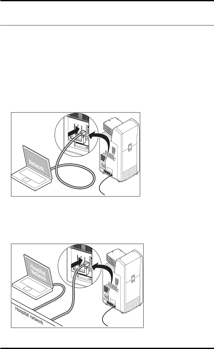
167
2900H EN 20071108 Controlling the Drystar 5500 via a remote PC (with browser)
DRYSTAR 5500/5503 REFERENCE MANUAL
Setup
The Drystar 5500 and the remote PC can be set up in two ways:
•using a crossed network cable, or
•using a straight network cable.
Configuration with crossed network cable
In this configuration, a crossed network UTP cable is used to connect the PC
directly to the printer.
Configuration with straight network cable
In this configuration, the PC is connected to the network with a straight
network cable.
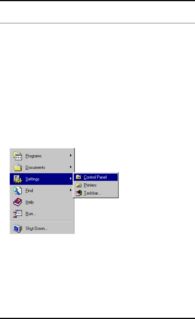
168 2900H EN 20071108Controlling the Drystar 5500 via a remote PC (with browser)
DRYSTAR 5500/5503 REFERENCE MANUAL
Setting up the connection
Setting up a direct link (configuration with crossed network
cable)
To set up a direct link, you have to follow two procedures:
•Attribute a fixed IP address to the PC,
•Switch off all proxy setting in the browser.
When setting up a link, bare in mind the following important hints:
•Always make the physical connection first,
•Depending on the PC and/or Operating System, a reboot may be necessary
in order to make the new configuration work.
Attributing a fixed IP address to the PC
1Go to Settings via the Start menu of Windows and click Control Panel.
The Control Panel menu will appear.
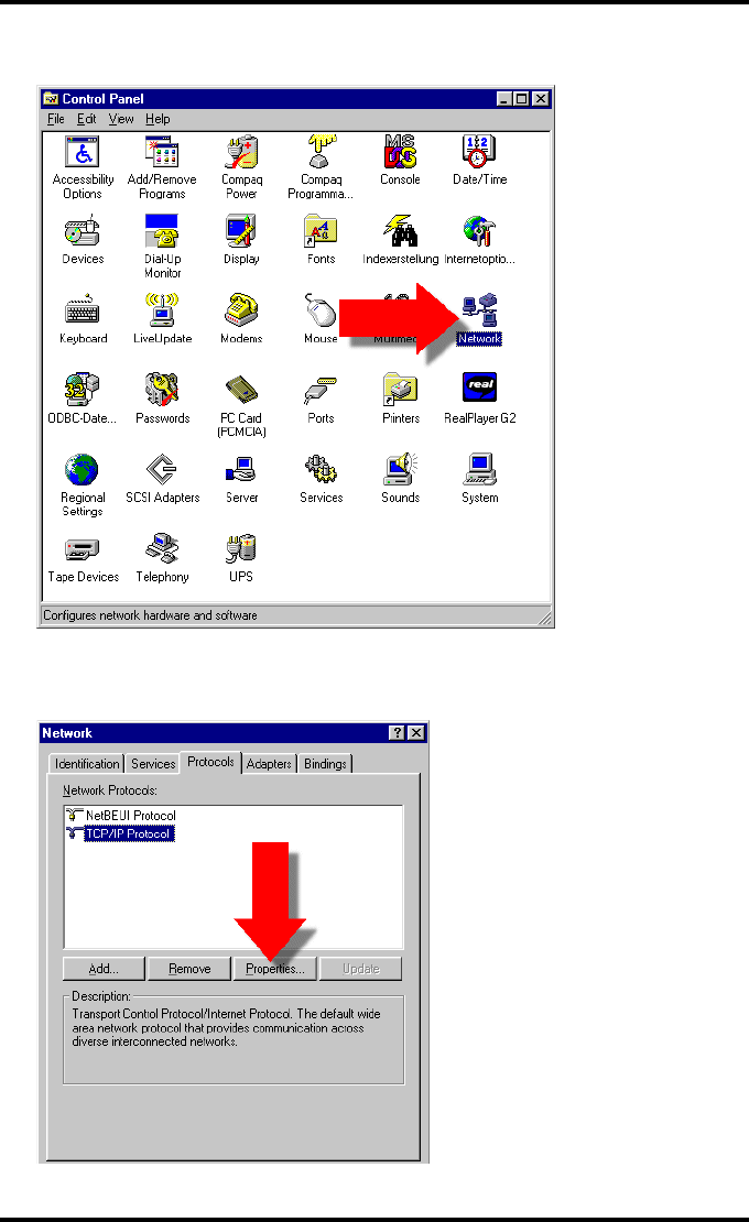
169
2900H EN 20071108 Controlling the Drystar 5500 via a remote PC (with browser)
DRYSTAR 5500/5503 REFERENCE MANUAL
2In the Control Panel menu, click Network.
3In the Network window, select TCP/IP protocol, select the Protocols tab, and
click Properties.
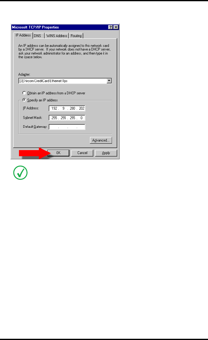
170 2900H EN 20071108Controlling the Drystar 5500 via a remote PC (with browser)
DRYSTAR 5500/5503 REFERENCE MANUAL
4Specify IP address and subnet mask and click OK.
Switching off the proxy settings of the browser
1Open the browser.
2In the Tools menu, click Internet options.
The Internet Options window will appear.
In case of APIPA assigned addresses, set the printer IP address to 169.245.10.10 and
the printer subnet mask to 255.255.0.0.
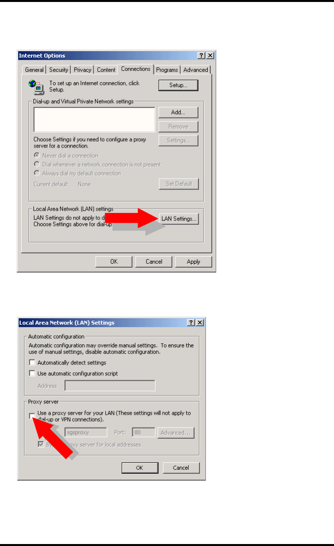
171
2900H EN 20071108 Controlling the Drystar 5500 via a remote PC (with browser)
DRYSTAR 5500/5503 REFERENCE MANUAL
3In the Internet Options window, go to the connection tab and click LAN
settings.
The Local Area Network (LAN) Settings window will appear.
4Switch off all proxy settings of the browser and click OK.
The PC is ready to make a connection. Refer to ‘Starting the remote session’ on page 173
for more information.

172 2900H EN 20071108Controlling the Drystar 5500 via a remote PC (with browser)
DRYSTAR 5500/5503 REFERENCE MANUAL
Setting up a link through a network (configuration with straight
network cable)
Attribute a fixed and available IP-address on the network to your PC. Refer to
‘Attributing a fixed IP address to the PC’ on page 168.
The PC is ready to make a connection. Refer to ‘Starting the remote session’ on page 173
for more information.
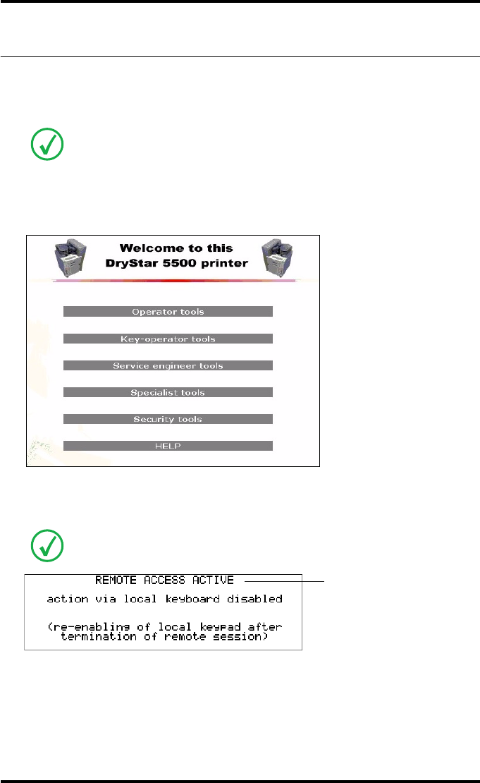
173
2900H EN 20071108 Controlling the Drystar 5500 via a remote PC (with browser)
DRYSTAR 5500/5503 REFERENCE MANUAL
Starting the remote session
Starting the remote session
To start the remote session, enter the IP address of the printer in the Address
bar of the browser.
The Browser welcome page appears:
There are five access levels: operator, Key-operator, service engineer, specialist and
security administrator. Each level, except the operator level, has its own user name
and password.
When starting the remote session, make sure the printer is in ‘Ready’ mode.
A remote session disables the local keypad and display. While you work remotely,
the following screen is displayed:
Blinking
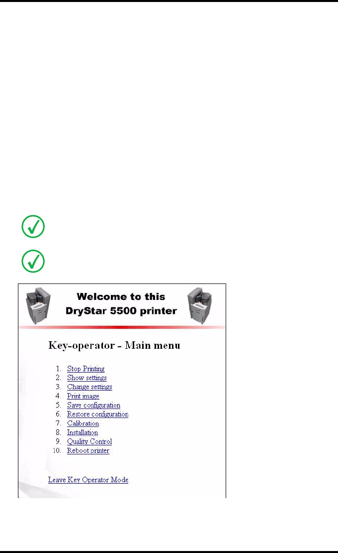
174 2900H EN 20071108Controlling the Drystar 5500 via a remote PC (with browser)
DRYSTAR 5500/5503 REFERENCE MANUAL
Entering the operator level
To enter the operator level, enter the following user name and password:
•User name: Operator
•Password: Operator
This level enables the operator to follow print jobs and perform common
tasks.
Entering the Key-operator level
To enter the Key-operator level, enter the following user name and password:
•User name: Drystar
•Password: 5500
You now have access to the functions in the Key-operator mode.
Only one session is active at one time on one printer.
Mostly, the menu structure and the browser screens are structured in the same way
as the local display of the printer. Sometimes they differ slightly as in following
example:

175
2900H EN 20071108 Controlling the Drystar 5500 via a remote PC (with browser)
DRYSTAR 5500/5503 REFERENCE MANUAL
The screens are in English only.
The functionality of some features is extended via Remote access. For example, you
can also print TIF-images which are “residing” on the Remote PC.
Do not use the Back and Forward buttons of your browser. Use the different links on
the pages instead.

176 2900H EN 20071108Controlling the Drystar 5500 via a remote PC (with browser)
DRYSTAR 5500/5503 REFERENCE MANUAL

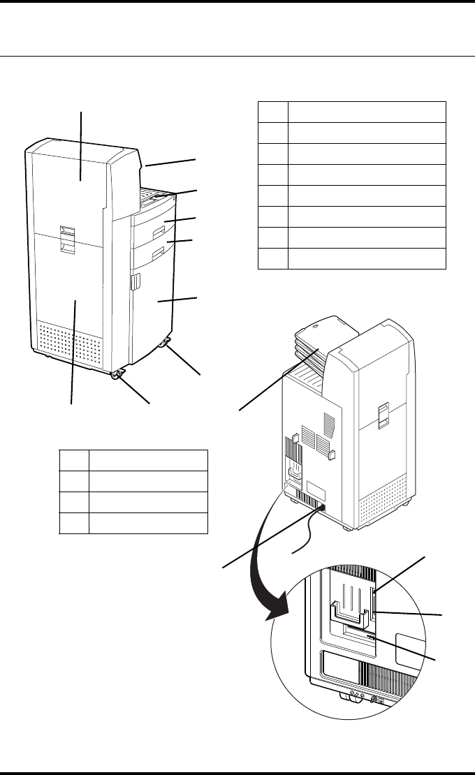
178 2900H EN 20071108System description
DRYSTAR 5500/5503 REFERENCE MANUAL
Main components
1Output tray
2User interface
3Upper input tray
4Lower input tray
5Front door
6Top door
7Drum compartment door
8Wheels with brakes
3
6
1
2
4
5
8
8
7
9
10
12
1
9Network connector
10 PC connector
11 Power connector
12 Floppy disk drive
11
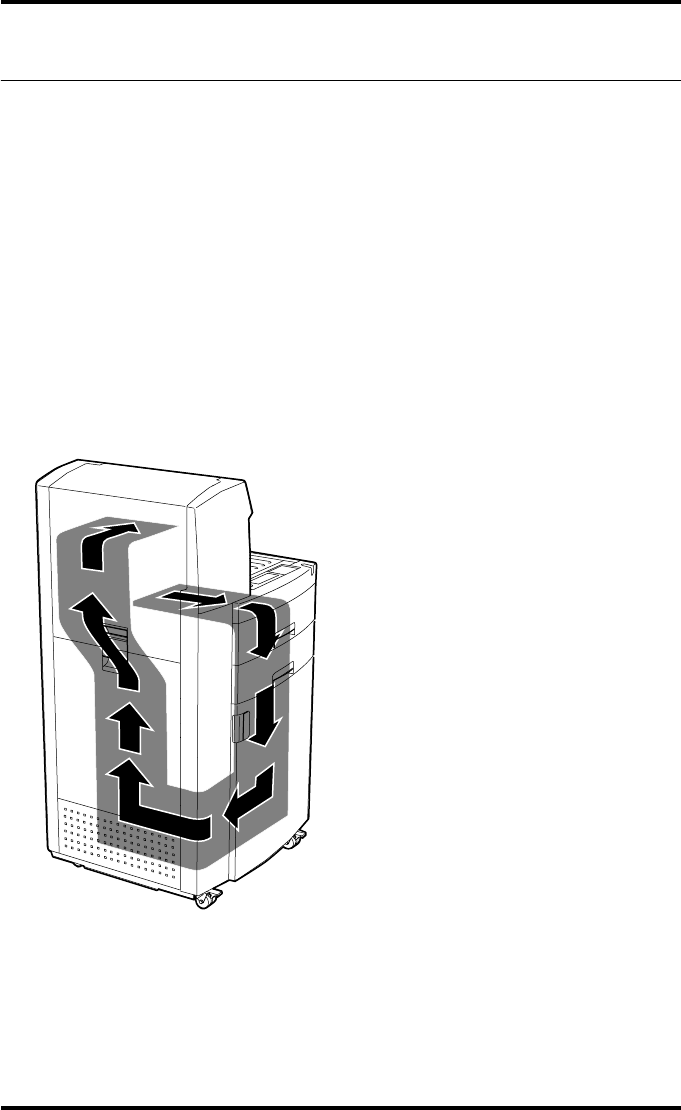
179
2900H EN 20071108 System description
DRYSTAR 5500/5503 REFERENCE MANUAL
Functional description
The Drystar 5500 consists of two functional blocks: a controller and a print
engine.
The controller
•captures the incoming digital data via the network and stores the data on a
hard disk,
•composes the different images, and
•generates the appropriate print engine control signals.
The print engine receives the image data from the controller, drives the film
through the device and makes grayscale prints.
The diagram below shows how the film is transported through the printer
(gray section in the drawing below).
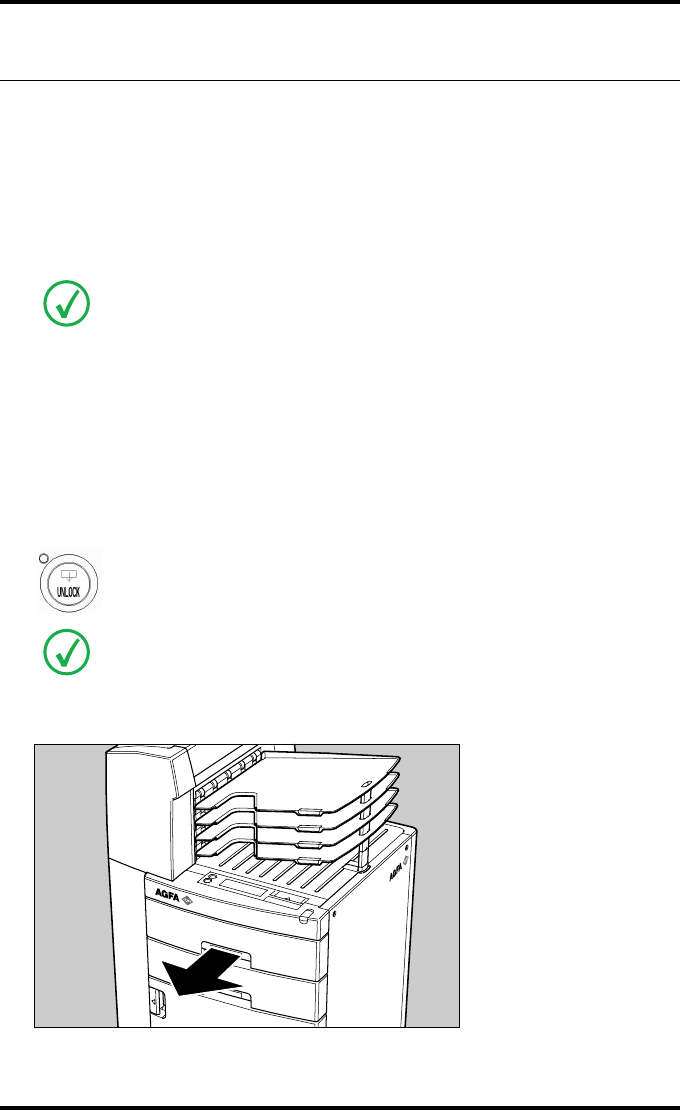
180 2900H EN 20071108System description
DRYSTAR 5500/5503 REFERENCE MANUAL
Changing the film format of the trays
The Key-operator can adjust the film size setting of both the input trays and
the output tray (8x10” up to 14x17” film sizes).
First, the Key-operator has to perform a mechanical modification. After this
modification, the ‘film format’ parameter is automatically read from the Film
Identification tag when the new film pack is loaded.
Proceed as follows to perform the mechanical modification:
1Make sure that the printer is in ‘Ready’ mode.
2Press the Unlock button to unlock the trays.
3Open the input tray you want to adapt.
Never load another film format when the input tray is not empty. Intermediate
changing of film formats increases the risk for dust, which can damage the thermal
print head (TPH).
The system performs an automatic calibration when the film format has been
changed.
You have 5 seconds to open the input tray. If you do not open the tray within that
time, the first screen (step 1 or 5 respectively) is presented again, or printing is
resumed when a job is received for which media is available.
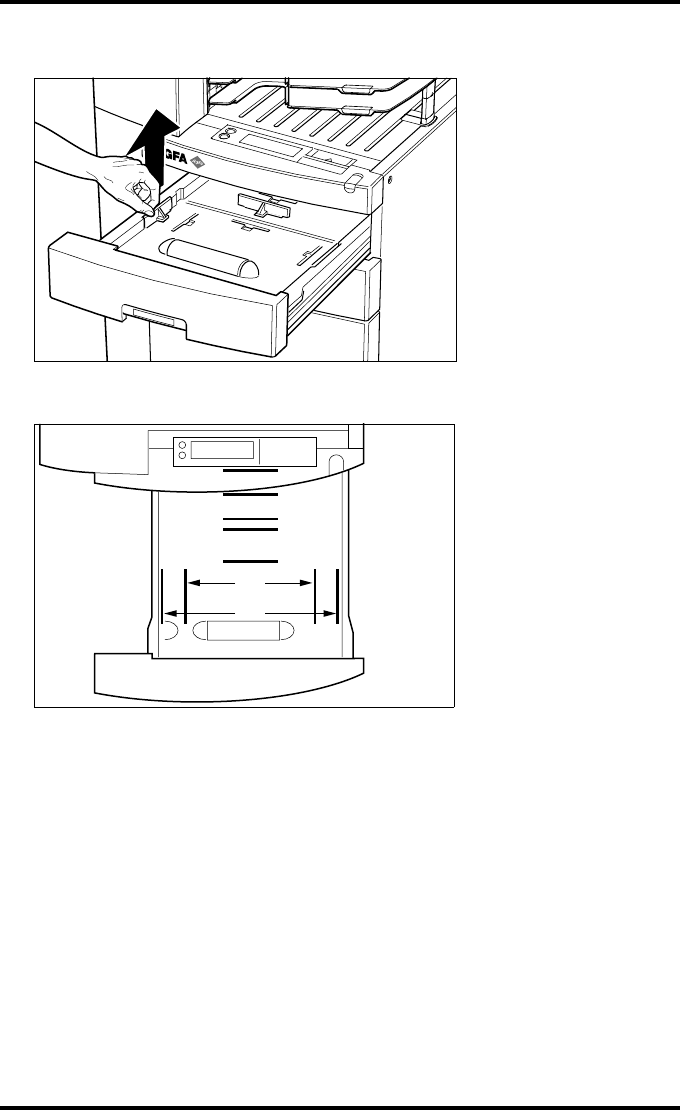
181
2900H EN 20071108 System description
DRYSTAR 5500/5503 REFERENCE MANUAL
4Remove the film position tab.
5Locate the correct tab position for the desired film format.
8"
11"
12"
14"
10"
14"
17"
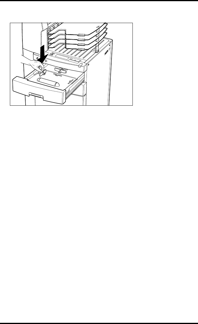
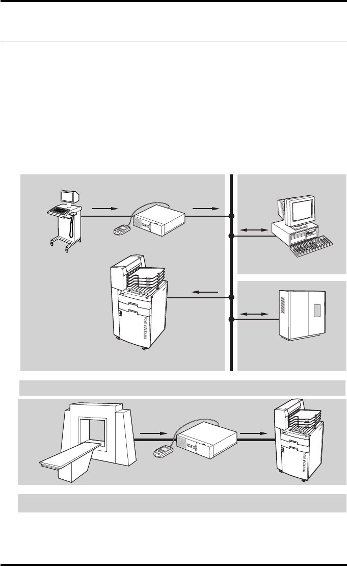
183
2900H EN 20071108 System description
DRYSTAR 5500/5503 REFERENCE MANUAL
Drystar 5500 network configuration
In a network configuration, the Drystar 5500 is fully compatible with Agfa’s
diagnostic imaging systems, including the ADC Compact and ADC Quality
System software, the Paxport and the entire line of Impax Review Systems,
Storage Stations and Transmitting Stations.
The Drystar 5500 serves as a standard network printer. Acquisition, storage,
transmission and printing are completely controlled by network modalities.
As network protocols the standard Agfa protocol or the optional DICOM
protocol can be used.
* Paxport is required if the modality is not a DICOM modality.
Paxport
Modality
Drystar 5500 Storage device
ADC QS on PC
Network
Images
Example of the Drystar 5500 in a network configuration
*
Paxport
Example of a Drystar 5500 in a point-to-point configuration
Modality Drystar 5500
*
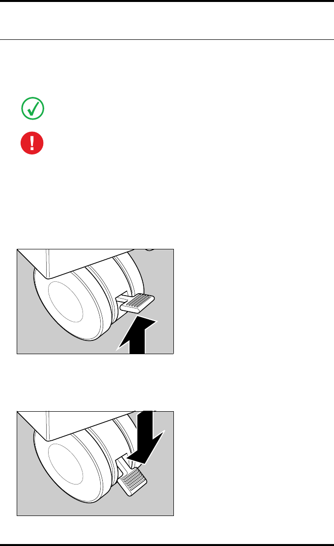
184 2900H EN 20071108System description
DRYSTAR 5500/5503 REFERENCE MANUAL
Transport after installation
The Drystar 5500 is equipped with wheels so that moving the printer over a
short distance - if required - can be done in a convenient way.
•During movement of the Drystar 5500 take care that stability is always
ensured. Special attention should be paid to possible obstructions, and to
uneven or slant surfaces.
•Never transport the Drystar 5500 with open doors.
•Make sure that both front wheel brakes are unlocked.
1Unlock both wheel brakes on the right and left hand sides.
2Move the Drystar 5500 to its destination.
3Relock the wheels by pressing the brakes down.
Refer to ‘Safety precautions’ on page 13.
Always keep in mind the following safety guidelines:

186 2900H EN 20071108Preventive maintenance and replacements
DRYSTAR 5500/5503 REFERENCE MANUAL
Preventive maintenance schedule
The Drystar 5500 is designed for trouble-free operation. Maintenance and
cleaning involve only some minor user tasks. Refer to the following pages for
the appropriate cleaning procedure.
Safety guidelines
•Do not lubricate the printer.
•Do not attempt to disassemble the printer.
•Do not touch the resistor line of the print head.
•Always switch off the Drystar 5500 and disconnect the power cord from
the outlet before carrying out any maintenance work.
Interval What to do? Page
Ad hoc ‘Cleaning the exterior’ 187
Ad hoc ‘Print head cleaning’ 115
Ad hoc ‘Cleaning the dust rollers’ 188
Each 6 months
(or more if required).
‘Cleaning the cooling air flow
holes’ 192
When image quality tends to
degrade. ‘Print head profile calibration’ 118
To prevent damage to the printer while performing maintenance, observe
the following safety precautions:
Film jam removal or cleaning the printer head can be done without switching the
power off.

187
2900H EN 20071108 Preventive maintenance and replacements
DRYSTAR 5500/5503 REFERENCE MANUAL
Cleaning the exterior
1Switch off the Drystar 5500 by following the procedure as described in
‘Switching off the Drystar 5500’ on page 36.
2Remove the power plug from the socket.
3Remove the network cable.
4Wipe the exterior of the printer with a clean, soft, damp cloth.
Use a mild soap or detergent if required but never use an ammonia-based cleaner. Be
careful not to get any liquid in the power cord port.
5Plug in the printer and switch it on by following the procedure as described in
‘Switching on the Drystar 5500’ on page 34.
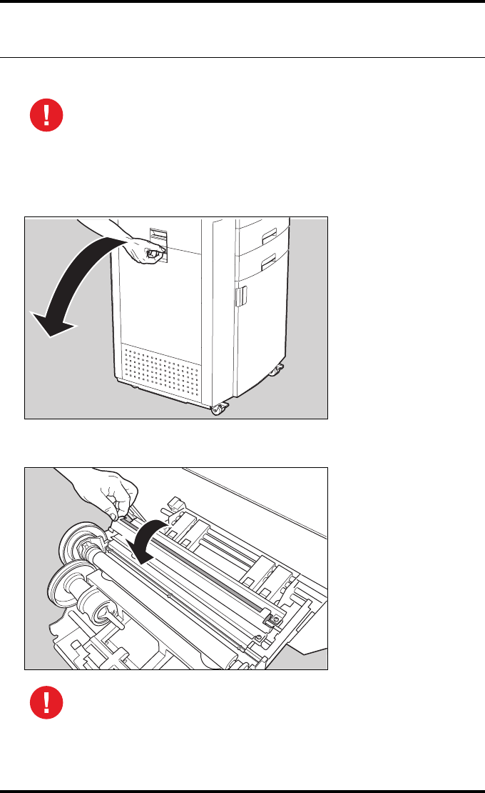
188 2900H EN 20071108Preventive maintenance and replacements
DRYSTAR 5500/5503 REFERENCE MANUAL
Cleaning the dust rollers
To clean the dust rollers, proceed as follows:
1Open the drum compartment door by pulling its handle.
2Open the sheet metal cover of the dust rollers.
Cleaning the dust rollers must be done when white lines appear on the
prints. For more information on maintaining image quality, refer to
‘Maintaining image quality and resolving Image quality problems’ on page 220.
Grab the cover at left side to avoid pinching of fingers.
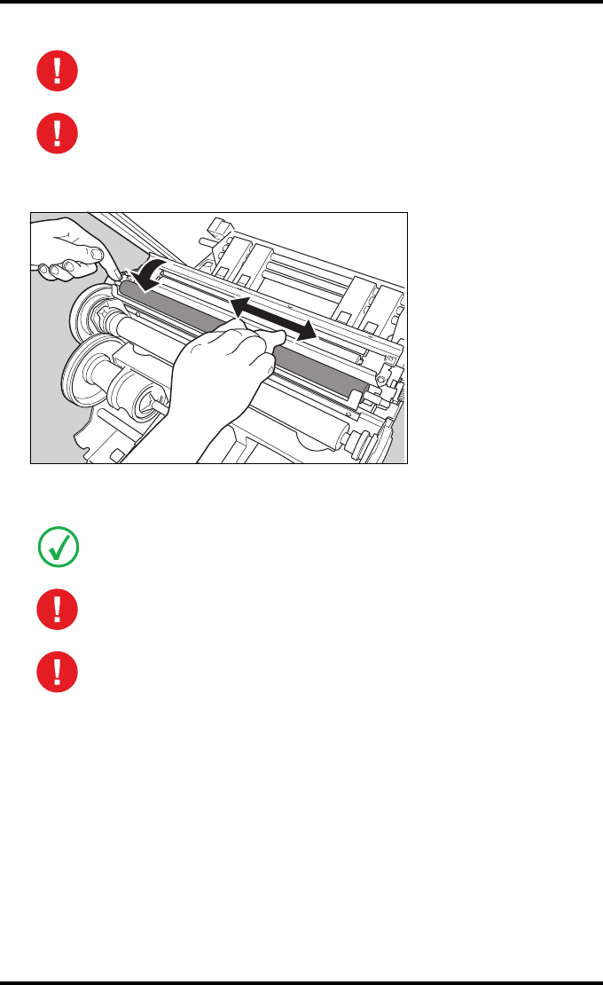
189
2900H EN 20071108 Preventive maintenance and replacements
DRYSTAR 5500/5503 REFERENCE MANUAL
3Clean the upper roller
Use a dust roller cleaning tissue to clean the roller. Turn the roller at its axle during
cleaning and rub in the length direction of the roller.
Do not touch the discharge brushes!
Keep all the other covers closed as much as possible to avoid extra dust
into the printer.
Refer to ‘ABC ordering codes’ for the ABC code of the dust roller cleaning tissue.
As the rollers are sticky it’s very important to use a lint free cloth!
Never clean the roller with water or soap.
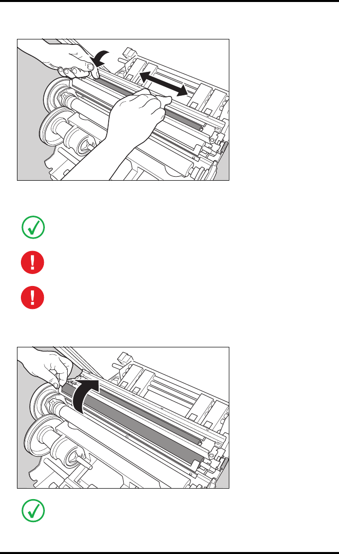
190 2900H EN 20071108Preventive maintenance and replacements
DRYSTAR 5500/5503 REFERENCE MANUAL
4Clean the lower roller
Use a dust roller cleaning tissue to clean the roller. Turn the roller at its axle during
cleaning and rub in the length direction of the roller.
5Close the sheet metal cover of the dust rollers.
Refer to ‘ABC ordering codes’ for the ABC code of the dust roller cleaning tissue.
As the rollers are sticky it’s very important to use a lint free cloth!
Never clean the roller with water or soap.
Grab the cover at left side to avoid oppressing of hands.

191
2900H EN 20071108 Preventive maintenance and replacements
DRYSTAR 5500/5503 REFERENCE MANUAL
6Close the drum compartment door.
After you have cleaned the dust rollers and you have closed the drum compartment
door, the printer will restart automatically.
After the cleaning the level of dust stripes can be slightly increased depending on
the amount of dust coming into the printer during the repair work. The level of dust
stripes usually improves after several prints (max. 1 film pack).
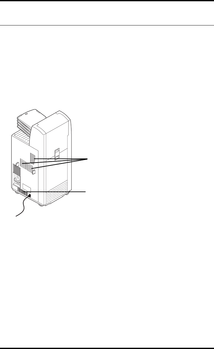
192 2900H EN 20071108Preventive maintenance and replacements
DRYSTAR 5500/5503 REFERENCE MANUAL
Cleaning the cooling air flow holes
1Switch off the Drystar 5500 by following the procedure as described in
‘Switching off the Drystar 5500’ on page 36.
2Remove the power plug from the socket.
3Remove the network cable.
4With a vacuum cleaner, clean the cooling air flow holes (item 1 and 2 on the
drawing below) , especially the CPU/power supply area (item 1).
5Plug in the printer and switch it on by following the procedure as described in
‘Switching off the Drystar 5500’ on page 36.
1
2

Troubleshooting
This chapter serves as a guide to identify and solve possible
problems you may encounter.
TTroubleshooting checklist
TThe Drystar 5500 does not print
TClearing of film jams
TFilm identification problems
TStart-up errors
TMaintaining image quality and resolving Image qual-
ity problems
TWarning messages
Chapter 7

194 2900H EN 20071108Troubleshooting
DRYSTAR 5500/5503 REFERENCE MANUAL
Troubleshooting checklist
General problems
The table below lists some general problems which can occur when working
with the Drystar 5500.
•The Drystar 5500 does not print.
•The quality of the printed images is bad (printing remains possible).
Action Refer to Page
Check the Drystar 5500 ‘The Drystar 5500 does not print’ 196
Remove a jammed film
‘Film input tray feed jams’ 200
‘Film transport jams in the front
section’ 203
‘Film transport jams in the print
section’ 205
‘Film transport jams in output
section’ 209
‘Unauthorized opening of the
printer’ 213
Resolve error messages ‘Checking error messages’ 196
Handle floppy disk error ‘Checking floppy disk error
messages’ 198
Action Refer to Page
Resolve film quality problems
‘Maintaining optimal Image Quality’ 220
‘White dots or lines appear in the
transport direction’ 223
‘Low frequency banding’ 223
‘Scratches appear on film’ 224
Resolve warning messages ‘Warning messages’ 225
Have electrical or mechanical defects repaired by skilled personnel only!
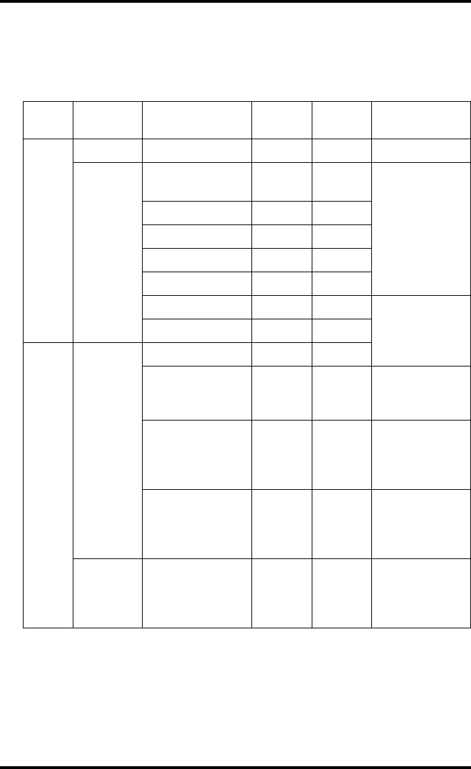
195
2900H EN 20071108 Troubleshooting
DRYSTAR 5500/5503 REFERENCE MANUAL
Checking the status indicator LED
The LED on the front panel indicates the Drystar 5500 operating status. Use
the following table to determine the status of your printer.
Color Light Status Receive
jobs?
Printing
OK? Action
Green
Constant Ready (standby) Yes Yes Proceed.
Blinking
Start-up
sequence No No
Wait.
Receiving jobs Yes Yes
Calculating Yes Yes
Printing Yes Yes
Calibrating Yes No
Installation No No
Proceed with
the activity.
Key-operator Yes/No Yes/No
Red
Blinking
Service mode No No
Upper/Lower
Input tray empty Yes Yes/No
Refer to
‘Loading films’
on page 46.
Film jam Yes No
Refer to
‘Clearing of film
jams’ on
page 199.
Warning Yes Yes
Refer to
‘Warning
messages’ on
page 225
Constant Error status No No
Refer to
‘Checking error
messages’ on
page 196.
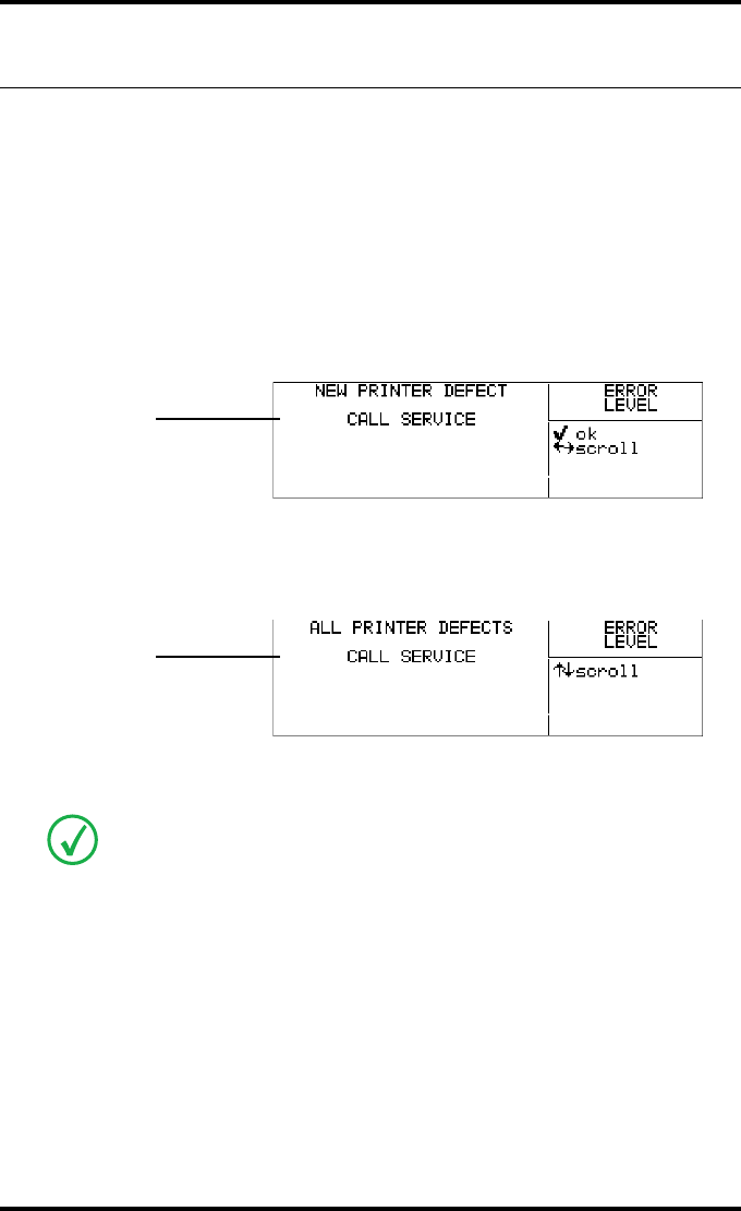
196 2900H EN 20071108Troubleshooting
DRYSTAR 5500/5503 REFERENCE MANUAL
The Drystar 5500 does not print
Proceed as follows when the Drystar 5500 does not print:
Checking error messages
1Check the display messages
If the Drystar 5500 is not printing your job, you should check the front panel display
to see if the Drystar 5500 is indicating an error status.
The operator is notified of the situation by means of an Error screen and a beep:
2Acknowledge the new error condition.
A new Ready screen will appear, holding all error messages. With the Up and Down
keys you can scroll through the error messages:
3Call the service operator.
An error message is different from a warning message. A warning means that an
event occurred which might result in a decreased image quality. Printing is still
possible, which is not the case when an error message appears.
ERROR CODE
ERROR CODE
ERROR CODE
ERROR CODE
Blinking
ERROR CODE
ERROR CODE
ERROR CODE
ERROR CODE
Blinking
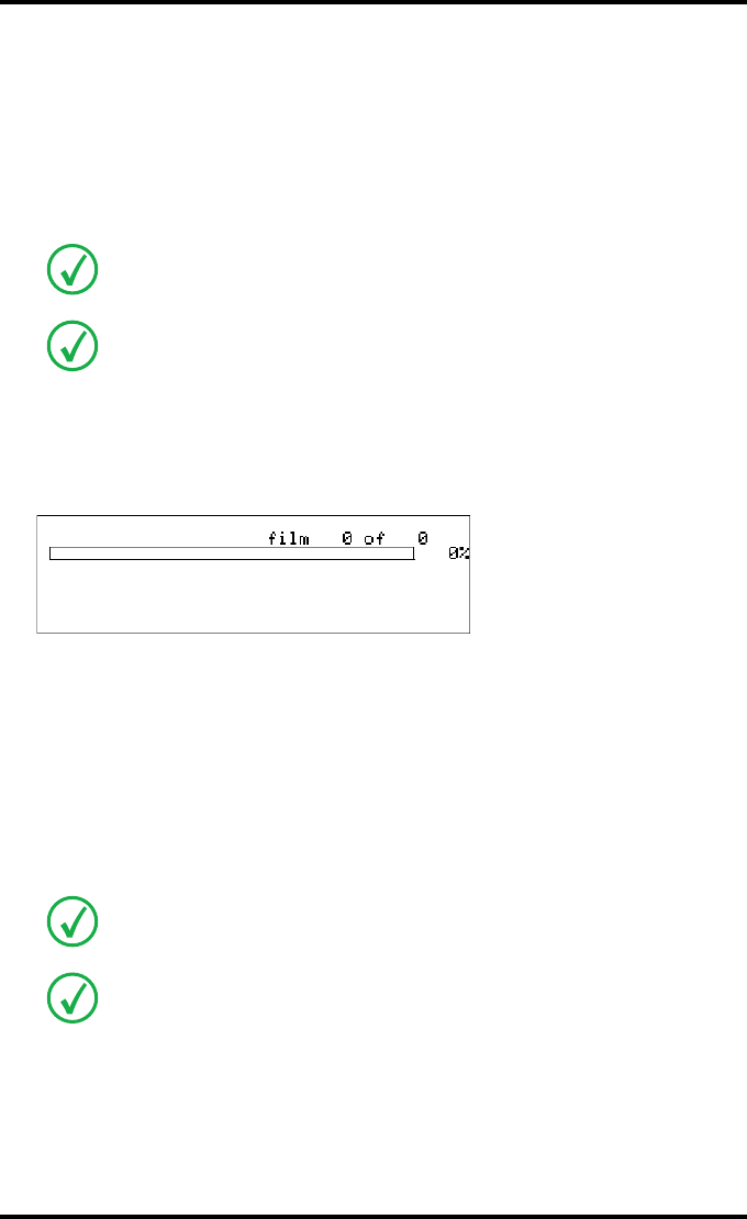
197
2900H EN 20071108 Troubleshooting
DRYSTAR 5500/5503 REFERENCE MANUAL
Checking the connections
If no error messages are displayed and you are unable to get the printer to
respond, the problem may be caused by a fault in the connections. In this
case, check that all connectors and cables are firmly attached to the printer.
•If the connections are OK, reset the Drystar 5500.
•If the Drystar 5500 still does not print, consult your local service organization.
Checking the print queue
If no error message is displayed, you should check the print queue:
For each line of the queue, the status can be:
•printing,
•calculating,
•waiting,
•warning,
•error.
A warning or error status indicates that there is a print queue problem.
Regularly check all electrical connections. When interference occurs with other
devices, consult your local service organization.
Call your local service organization in case cables are disconnected. The user is not
allowed to add or remove any connectors.
For more information, refer to ‘Warning messages’ on page 225 and ‘Start-up
errors’ on page 218.
For more information about the print queue status, refer to ‘Managing the print
queue’ on page 39.
<Modality name> 10:21:34 PRINTING
1 2
<Modality name> 10:21:34 CALCULATING
<Modality name> 11:35:27 WAITING
<Modality name> 11:54:02 WAITING

198 2900H EN 20071108Troubleshooting
DRYSTAR 5500/5503 REFERENCE MANUAL
Checking floppy disk error messages
If the Drystar 5500 is not printing your job, you should check the front panel
display to see if the Drystar 5500 is indicating an error status.
A floppy disk error can occur when the inserted floppy disk is full, write
protected or when no floppy disk is inserted.
1Correct the error following the error message on the screen:
After you have corrected the action the screen will disappear.
<error message> Blinking
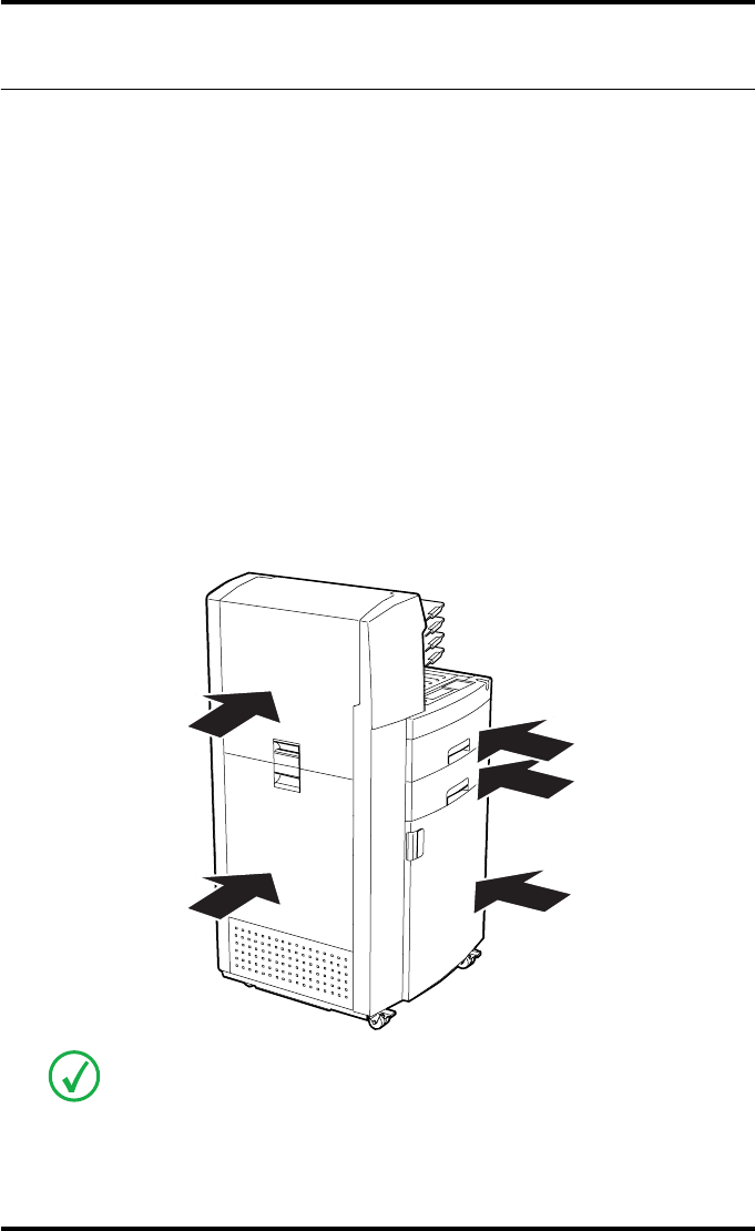
199
2900H EN 20071108 Troubleshooting
DRYSTAR 5500/5503 REFERENCE MANUAL
Clearing of film jams
A film jam can be situated either:
•In the input tray section. Refer to ‘Film input tray feed jams’ on page 200.
•In the alignment section. Refer to ‘Film transport jams in the front section’
on page 203.
•In the drum and print head section. Refer to ‘Film transport jams in the print
section’ on page 205.
•In the sorter/exit section. Refer to ‘Film transport jams in output section’ on
page 209.
Jams can be caused by:
•Loading consumables in a wrong way, e.g. loading film upside down.
•Opening the printer door(s) or input tray(s) while a film is actually being
printed. Refer to ‘Unauthorized opening of the printer’ on page 213.
Overview of sections:
A pictogram on the display depicts where the film jam is situated in the printer.
Film feed jams
(clearing from the
input trays)
Film transport jams
(clearing from the
alignment section)
Film transport
jams (clearing
from the sorter/
exit section)
Film transport
jams (clearing
from the drum and
print head
section)
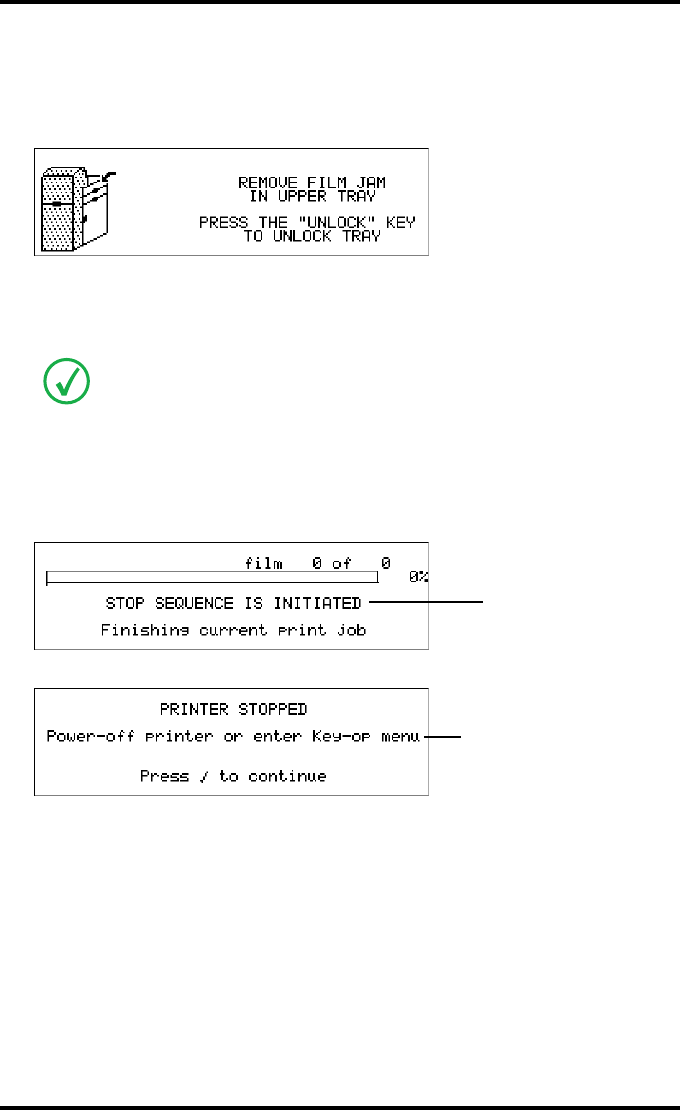
200 2900H EN 20071108Troubleshooting
DRYSTAR 5500/5503 REFERENCE MANUAL
Film input tray feed jams
The following screen indicates that a jam occurred in the feed section of the
input tray(s):
A message will inform you if either the upper or lower input tray is jammed.
To remove a jammed film in the input tray (e.g. upper input tray):
1Start the procedure to stop printing as described in ‘Stopping the printing
process’ on page 59.
2Wait while the printer is finishing printing any current jobs.
The printer is ready when the following message appears:
In the procedure, we will assume that the upper input tray is to be cleared. The
procedure for the lower input tray is identical.
<Modality name> 10:21:34 PRINTING
1 2
Blinking
Blinking
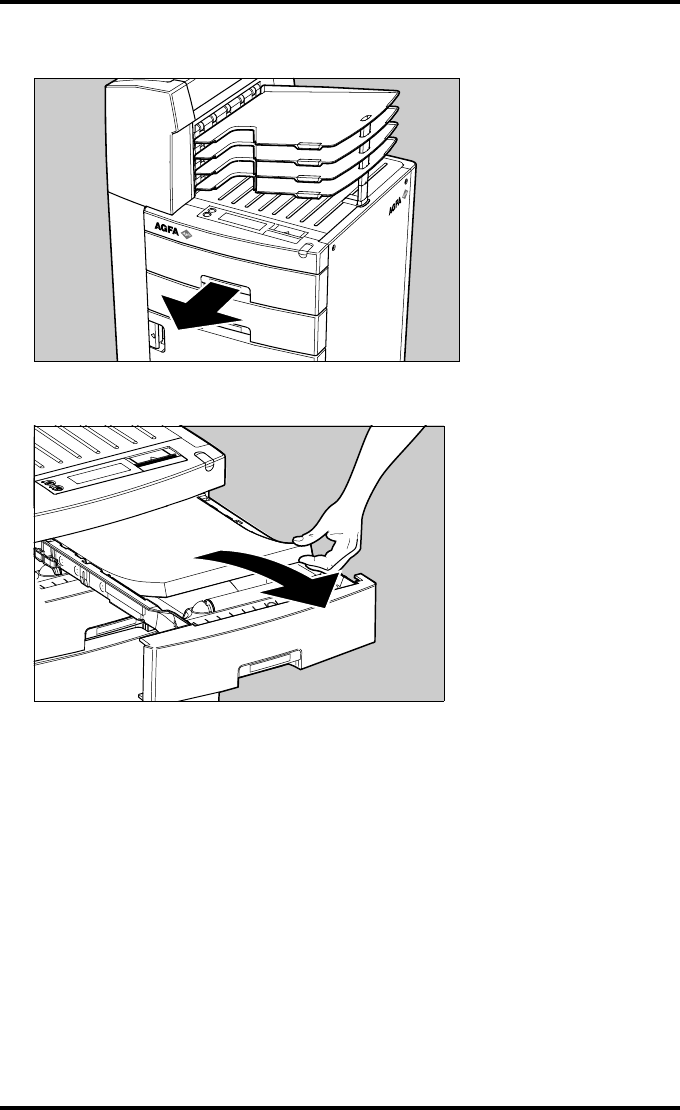
201
2900H EN 20071108 Troubleshooting
DRYSTAR 5500/5503 REFERENCE MANUAL
3Open the film input tray.
4To get a clear view, remove any remaining film sheets.
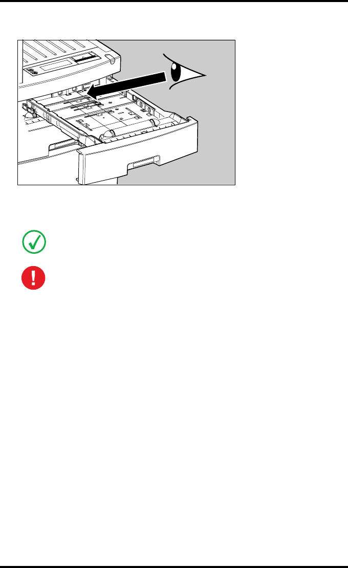
202 2900H EN 20071108Troubleshooting
DRYSTAR 5500/5503 REFERENCE MANUAL
5Check the film feed section of the input tray.
If a film is jammed, gently remove the sheet. Reposition the film stack in the input
tray, making sure that all the sheets are kept correctly in place (refer to ‘Loading films’
on page 46).
Never use force to clear the jammed film. If it is not possible to gently remove the
jammed film, call your local service organization.
Never reuse a jammed film. This may cause damage to the thermal head
and/or dust problems.
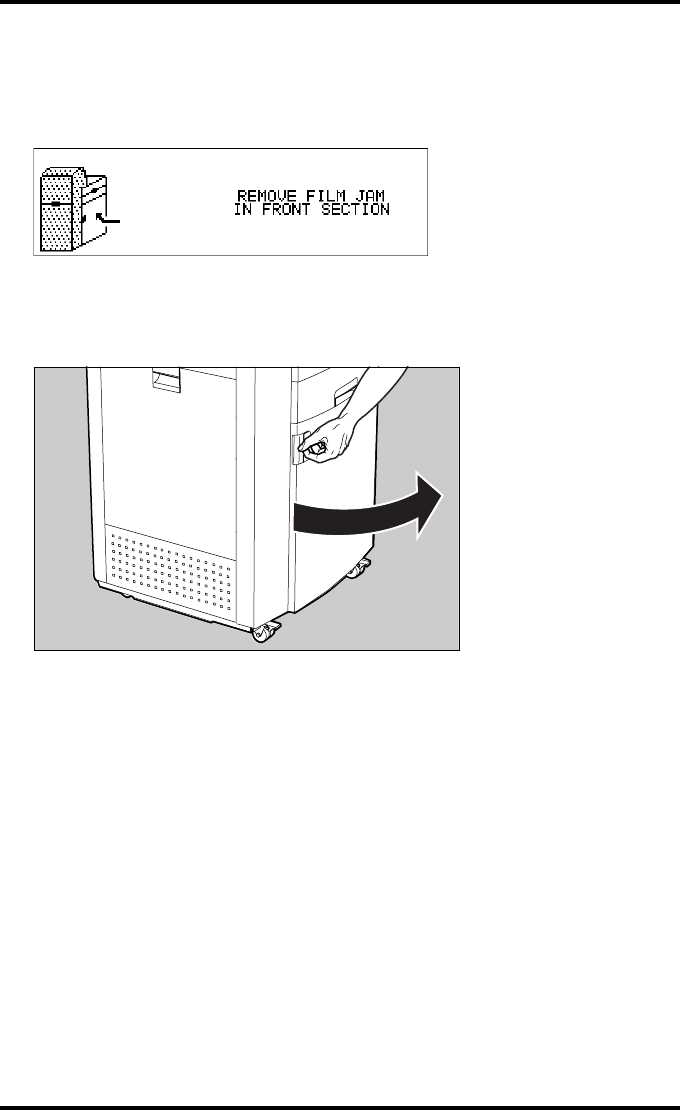
203
2900H EN 20071108 Troubleshooting
DRYSTAR 5500/5503 REFERENCE MANUAL
Film transport jams in the front section
The following screen indicates that a jam occurred in the front section of the
film transport system.
To remove a jammed film in the front section of the transport system:
1Pull the front door open.
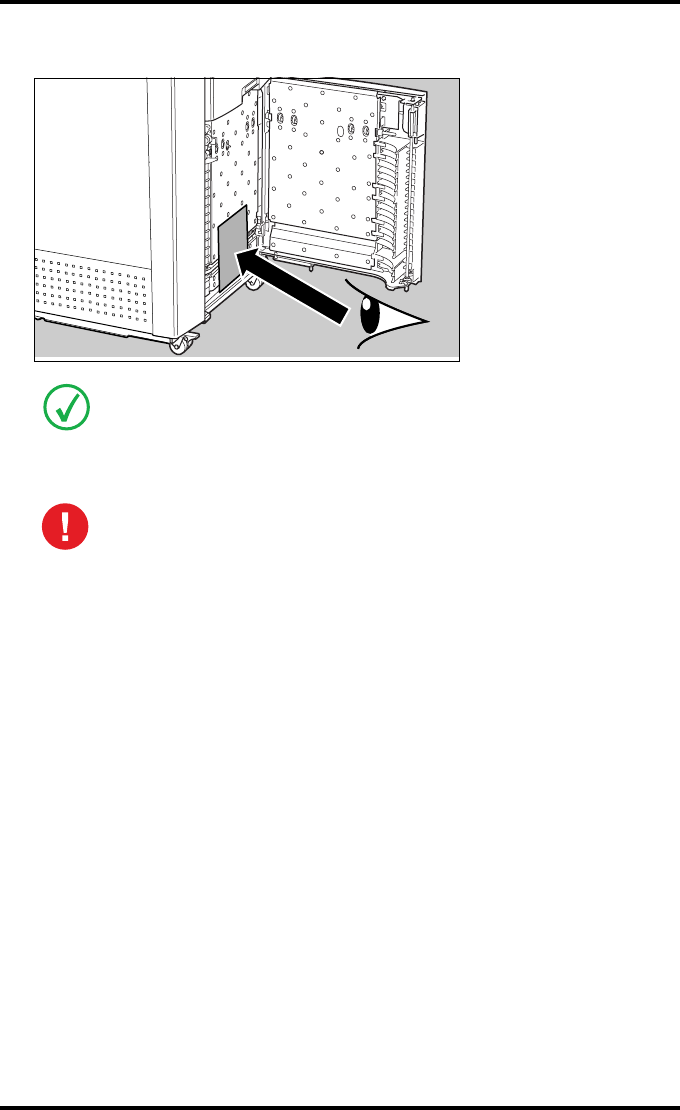
204 2900H EN 20071108Troubleshooting
DRYSTAR 5500/5503 REFERENCE MANUAL
2Check the interior for film sheets.
3Remove the film sheet.
4Close the front door and continue.
In many cases, the film will fall out of this section after you have opened the front
door.
NEVER reuse a film that you got back from a jamming situation, it may
damage the print unit.
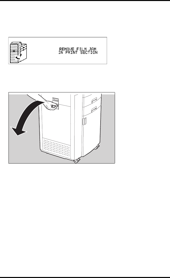
205
2900H EN 20071108 Troubleshooting
DRYSTAR 5500/5503 REFERENCE MANUAL
Film transport jams in the print section
The following screen indicates that a jam occurred in the print section of the
film transport system.
To remove a jammed film in the print section of the transport system:
1Open the drum compartment door by pulling its handle.
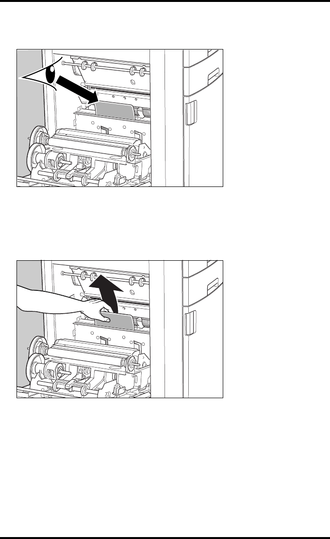
206 2900H EN 20071108Troubleshooting
DRYSTAR 5500/5503 REFERENCE MANUAL
2Check if you can locate a film visually between the vertical lift and the print
head.
•If the film is visible,
proceed with step 3.
•If the film is not visible, it has fallen behind the vertical lift.
Proceed with step 4.
3carefully remove the film and proceed with step 8.
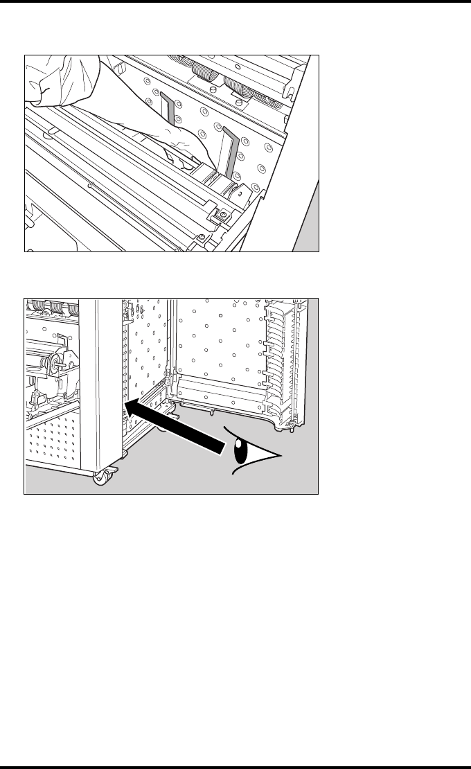
207
2900H EN 20071108 Troubleshooting
DRYSTAR 5500/5503 REFERENCE MANUAL
4Locate the film through the holes of the vertical lift and move it to the right.
5Open the front door and check the area behind the vertical lift.
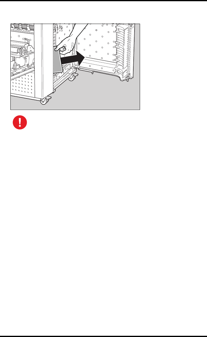
208 2900H EN 20071108Troubleshooting
DRYSTAR 5500/5503 REFERENCE MANUAL
6Remove the film via the front compartment, as indicated below.
7Close the front door.
8Close the drum compartment door and continue.
NEVER reuse a film that you got back from a jamming situation, it may
damage the print unit.

209
2900H EN 20071108 Troubleshooting
DRYSTAR 5500/5503 REFERENCE MANUAL
Film transport jams in output section
The following screen indicates that a jam occurred in the output section of the
film transport system.
To remove a jammed film in the output section of the transport system:
1Open the top door.
2Visually check where the film is jammed.
•If the film is jammed in the canting guide plate section,
proceed with step 3
•If the film is stuck in the sorter section,
proceed with step 7.
Mind your head when the top door is open.
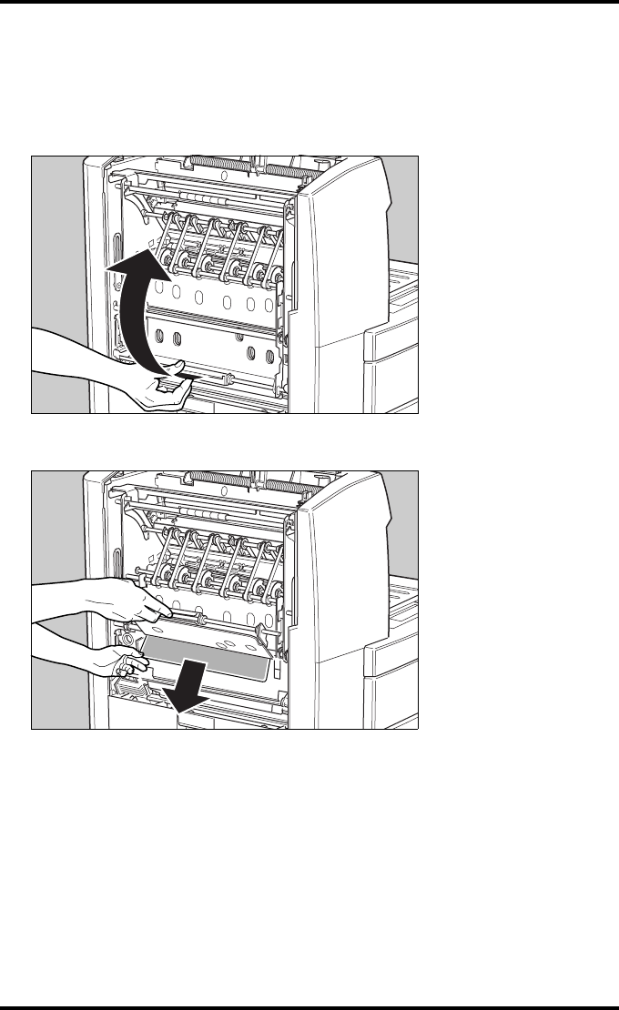
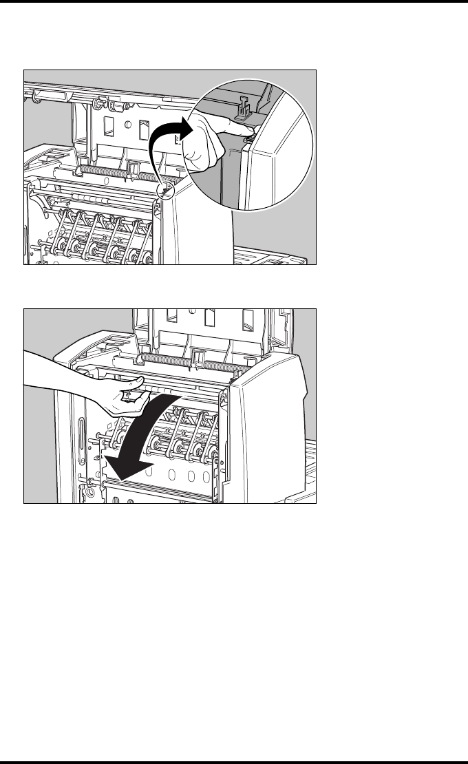
211
2900H EN 20071108 Troubleshooting
DRYSTAR 5500/5503 REFERENCE MANUAL
7Locate the film. First try to use the transport buttons to help clearing the
jammed film.
8Open this sorter unit as follows:
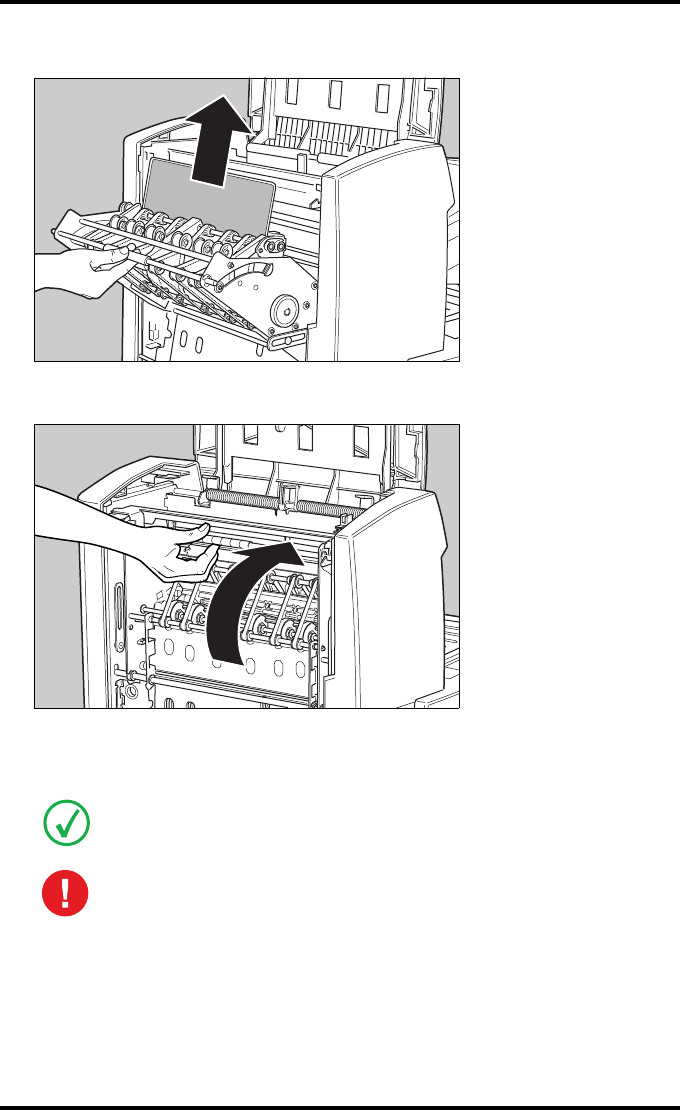
212 2900H EN 20071108Troubleshooting
DRYSTAR 5500/5503 REFERENCE MANUAL
9Remove the jammed film.
10 Close the section.
11 If the film jam has been cleared, close the printer.
You can resume work.
If the jam is not cleared at this moment, call you local service organization.
NEVER reuse a film that you got back from a jamming situation, it may
damage the print unit.
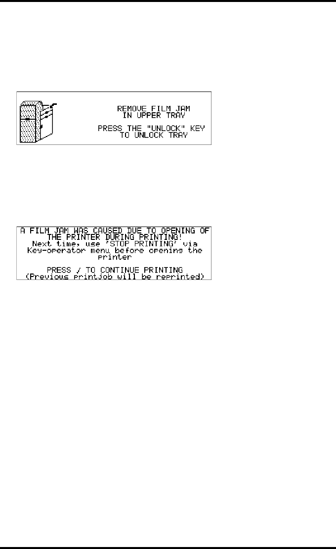
213
2900H EN 20071108 Troubleshooting
DRYSTAR 5500/5503 REFERENCE MANUAL
Unauthorized opening of the printer
A jam can be caused by opening the printer doors while a film is actually being
printed.
The following screen indicates that a jam has occurred.
Proceed as follows:
1Remove the jammed sheet.
Refer to ‘Clearing of film jams’ on page 199.
After removal of the jammed film, the user is informed that he caused the film jam by
opening the printer without using the appropriate procedure to stop printing.
2Make sure to follow carefully the procedures as described in this manual before
attempting to open the printer.
Refer to ‘Switching off the Drystar 5500’ on page 36.
Refer to ‘Loading films’ on page 46.
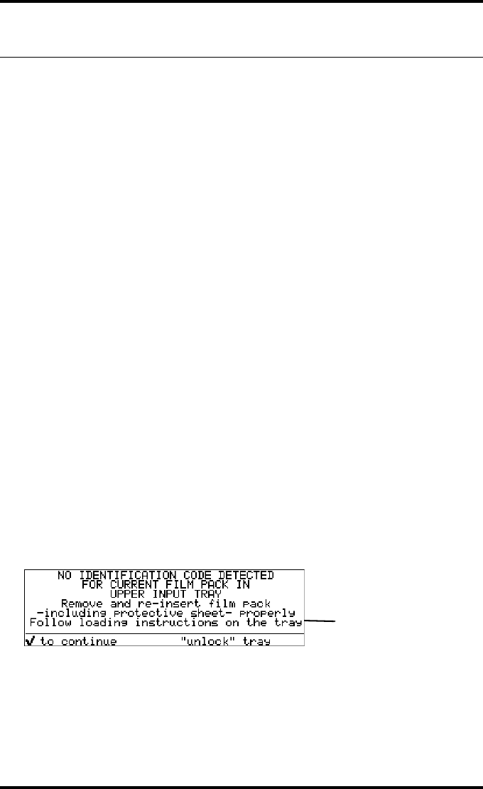
214 2900H EN 20071108Troubleshooting
DRYSTAR 5500/5503 REFERENCE MANUAL
Film identification problems
When you load a new film pack, the new Film Identification tag is read and
the tray film format and type are set based upon the info in the Film
Identification tag (RF-tag).
This tag is only readable when the film pack is inserted in the correct way.
There are four possible error messages regarding film identification:
•No identification code detected
•Identification code error for upper/lower input tray
•Identical identification code detected in upper/lower input tray
•Film overrun from current pack
The following sections descibe the solution for each of these problems in more
detail.
No identification code detected
This error message appears when the Film Identification tag is not readable.
There are two possible solutions for this problem:
•Reload the current film pack or load another film pack
•Overrule the Film Identification tag of the film pack
To reload the current or another film pack
1In case the Drystar 5500 does not start printing after re-inserting a film pack,
first check if this film pack is inserted correctly.
If the Drystar 5500 still does not resume printing, the following message will appear:
Blinking
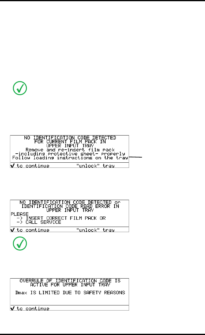
215
2900H EN 20071108 Troubleshooting
DRYSTAR 5500/5503 REFERENCE MANUAL
2Press the Unlock button to initiate the loading sequence and check again if the
film pack is inserted correctly. If you re-insert the film pack, the Drystar 5500
will perform the same check-sequence until printing is resumed.
To overrrule the Film Identification tag of the film pack
If the “Overrule RF-tag Reading” setting is active, you can overrule the Film
Identification tag setting of the current film pack. In this case you can
continue printing using a limited Maximum Density.
1In case the Drystar 5500 does not start printing after inserting a new film pack,
check if this film pack is inserted correctly.
If the film pack is inserted correctly and the Drystar 5500 does not resume printing,
the following message will appear:
2To continue with the current (not identified) film pack, press the Confirm
button.
The following message is displayed:
3Press the Confirm button.
If the “Overrule RF-tag Reading” Setting is active, the following message is displayed:
Only your local service organization has the possibility to enable the “Overrule RF-
tag Reading” setting!
If you wish, you can try again to re-insert the current or an other film pack. Press
the Unlock button to initiate the loading sequence. If you re-insert a film pack, the
Drystar 5500 will perform the check-sequence.
Blinking
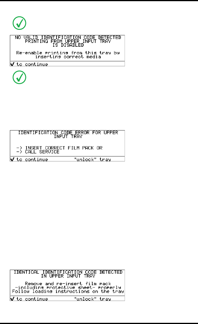
216 2900H EN 20071108Troubleshooting
DRYSTAR 5500/5503 REFERENCE MANUAL
4Press the Confirm key again to resume printing using a limited Maximum
Density.
Identification code error for upper/lower input tray
This identification code error appears in the following cases:
•you insert a new film pack with a encryption error in the Film
Identification tag,
•you have loaded a Mammo film pack or a Mammo film, whereas the
Mammo license is not activated.
Call your local service organization to resolve this problem. You can unlock
the tray to insert another film pack.
Identical identification code detected in upper/lower input tray
In case you have loaded a film pack with a non-unique Film Identification tag
(meaning that the current tag has been used with a previous film pack), the
following message is displayed:
Proceed as follows:
If the “Overrule RF-tag Reading” Setting is not activated, the following message will
be displayed:
In this case, press the Confirm key to initiate the loading procedure again or call
your local service organization to enable the “Overrule RF-tag Reading” Setting.
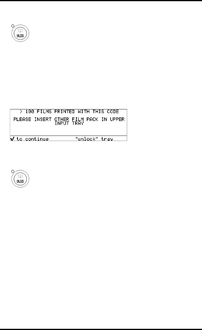
217
2900H EN 20071108 Troubleshooting
DRYSTAR 5500/5503 REFERENCE MANUAL
1Press the Unlock button to initiate the loading sequence.
2Reload a new film pack.
The Drystar 5500 will resume printing.
Film overrun from current pack
The following message is presented when more than 100 copies have been
printed from the current film pack:
Proceed as follows:
1Press the Unlock button to initiate the loading sequence.
2Reload a new film pack.
The Drystar 5500 will resume printing.
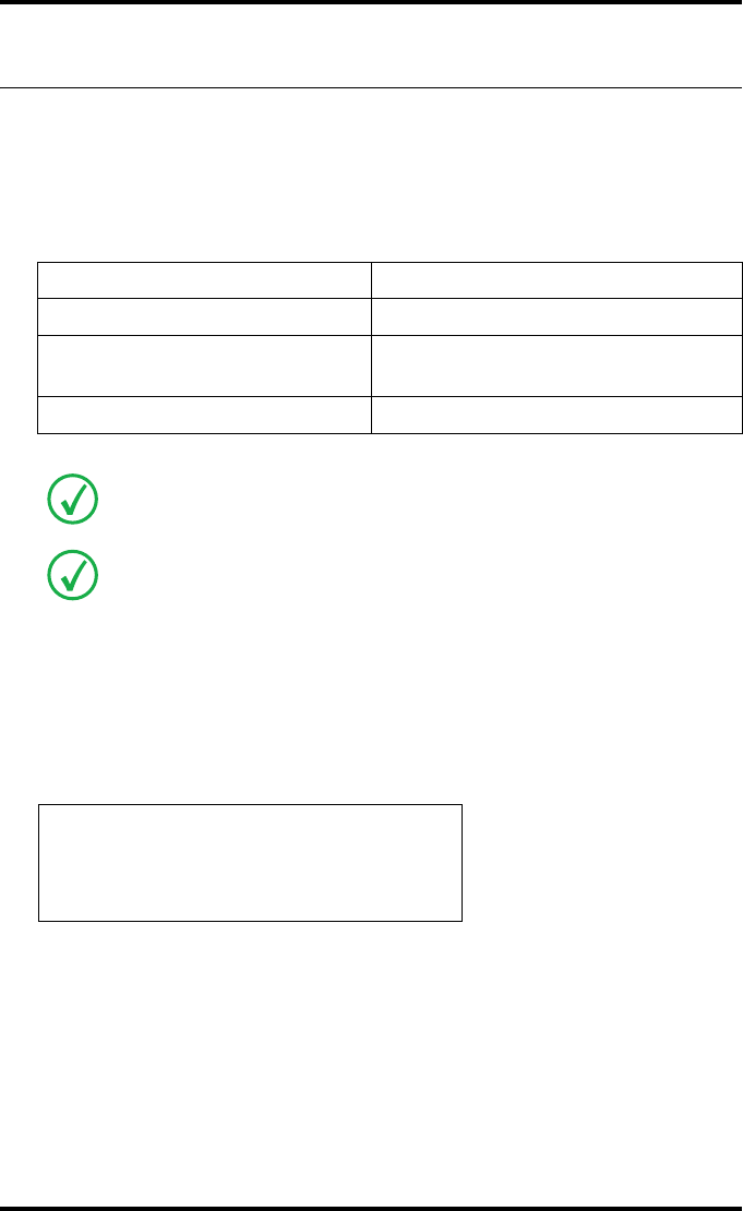
218 2900H EN 20071108Troubleshooting
DRYSTAR 5500/5503 REFERENCE MANUAL
Start-up errors
Error messages while the printer starts up
The table below lists the possible error messages which can appear on the
display of the control panel while the printer starts up.
After starting up the Drystar 5500, the printer performs a selftest. A progress
indicator will show the proceeding of this self test. During the self test, a
number of messages can appear, meaning that the selftest has failed.
Key selftest failed
In case the Key selftest has failed, following message appears:
Error message Cause of error
Error display failure (Firmware) ‘Key selftest failed’
Error system failure ‘Key selftest failed due to no
communication between Key and CPU’
Error self test failure (Firmware) ‘Software selftest failed’
Contact your local service organization in case the selftest fails.
Error messages can also appear when the printer has already started up. Refer to
‘Checking error messages’ on page 196.
ERROR
Display failure
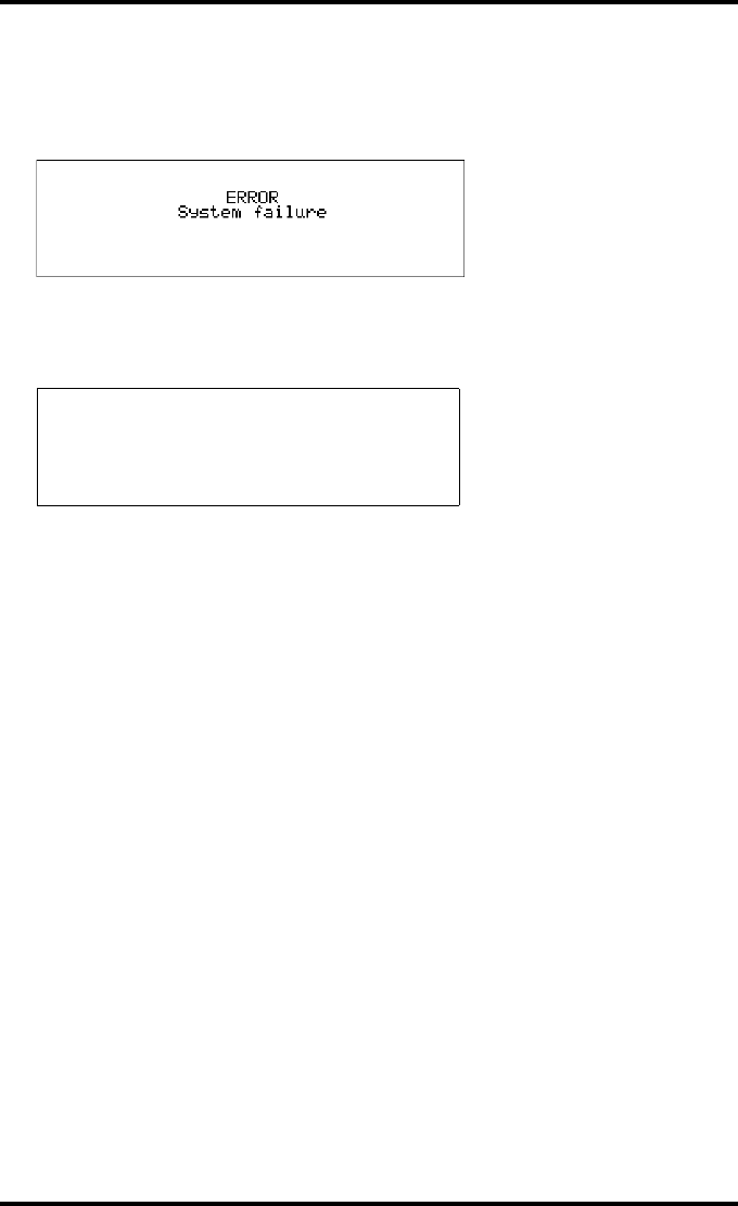
219
2900H EN 20071108 Troubleshooting
DRYSTAR 5500/5503 REFERENCE MANUAL
Key selftest failed due to no communication between Key and CPU
In case the Key selftest has failed due to no communication between Key and
CPU, following message appears:
Software selftest failed
In case the software selftest has failed, following message appears:
ERROR
Self test failed

220 2900H EN 20071108Troubleshooting
DRYSTAR 5500/5503 REFERENCE MANUAL
Maintaining image quality and resolving Image
quality problems
In general, when you follow the procedure ‘Maintaining optimal Image
Quality’ below, you should rarely encounter quality problems on printed
films.
However, should any problems occur, the paragraphs ‘White dots or lines
appear in the transport direction’ on page 223, ‘Low frequency banding’ on
page 223 and ‘Scratches appear on film’ on page 224 provide some specific
remedies.
Maintaining optimal Image Quality
Calibration is necessary to maintain optimal Image Quality. This is required in
the following situations:
•Before initial use of a film,
•When loading new films into the input trays,
•After a certain number of copies have been printed,
•After the replacement of the thermal head.
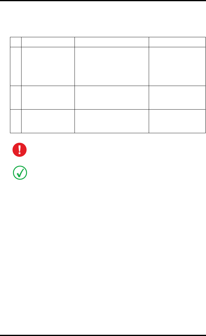
221
2900H EN 20071108 Troubleshooting
DRYSTAR 5500/5503 REFERENCE MANUAL
Overview of calibration functions
Three calibration functions are provided for the Drystar 5500.
Understanding the calibration policy and the calibration initiation
You should regularly perform a film calibration to assure that the image
quality remains optimal.
Film calibration can be initiated in 2 ways:
•Automatically, i.e. after loading every ‘x’ new film packs (automatic
initiation),
•Manually, i.e. you decide for yourself when to perform a film calibration,
e.g. daily, once a week, or only when the image quality tends to degrade.
For setting automatic or manual film calibration initiation, refer to ‘Changing
general image quality settings - Film calibration’ on page 91.
Calibration Purpose When?
1‘Film calibration’
• To measure and set the
system density of the
printer.
• To measure and set the
film sensitometry values.
•Automatic.
• After an explicit
action of the
operator.
2‘Print head cleaning’ To eliminate white dots or
lines in transport direction.
•When image
quality problems
occur.
3‘Print head profile
calibration’
To reduce vertical density
irregularities on the film.
• After an explicit
action of the
operator.
Some calibration functions are interrelated, so do not perform any of the
above calibration functions as an isolated procedure.
Before performing a calibration, read the general guidelines as described in
‘Understanding the calibration policy and the calibration initiation’ on page 221.
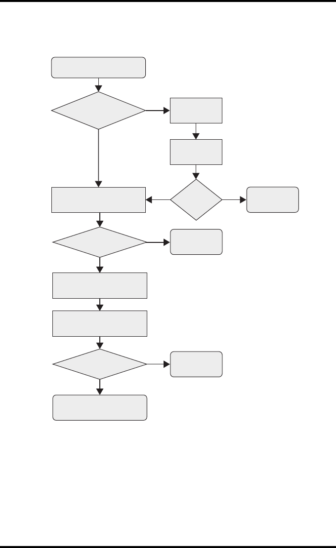
222 2900H EN 20071108Troubleshooting
DRYSTAR 5500/5503 REFERENCE MANUAL
The following flowchart will assist you in determining the correct operation
in order to maintain the optimal image quality from your printer:
Image
Quality OK?
NO
YES
Persistent
White Dots or
Lines?
Start
Call Service
Done
Clean Dust
Rollers
YES
NO
Clean
Print Head
Image
Quality
OK?
Image
Quality OK?
NO
YES Done
YES Done
Perform Film Calibration
Perform Print Head
Profile Calibration
Perform Film Calibration
NO

223
2900H EN 20071108 Troubleshooting
DRYSTAR 5500/5503 REFERENCE MANUAL
White dots or lines appear in the transport direction
If fine white dots and one or more fine white lines appear in the transport
direction (mostly due to dust infiltration), try the following remedies:
1Clean the print head resistor line.
Refer to ‘Print head cleaning’ on page 115.
2If dust stripes remains visible, clean the dust roller.
Refer to ‘Cleaning the dust rollers’ on page 188.
3Print a few test sheets using the ‘Print test image’ function.
Refer to ‘Printing test images from the hard disk’ on page 101.
4If the white lines are still visible, contact your local service organization.
Low frequency banding
If you notice density non uniformity (low frequency banding) in the print
head direction, perform print head profile calibration.
Refer to ‘Print head profile calibration’ on page 118.
Use a lint free cloth, slightly moistened with Isopropyl alcohol or Ethanol.
As the rollers are sticky it’s very important to use a lint free cloth!
Never clean the roller with water or soap.

224 2900H EN 20071108Troubleshooting
DRYSTAR 5500/5503 REFERENCE MANUAL
Scratches appear on film
If you notice scratches on the film in the print head direction, this may be due
to the fact that a film sheet has been placed upside-down in the input tray.
Refer to ‘Checking the correct position of a film in the input tray’ on page 54.
Verify the correct position of the films in the input trays.
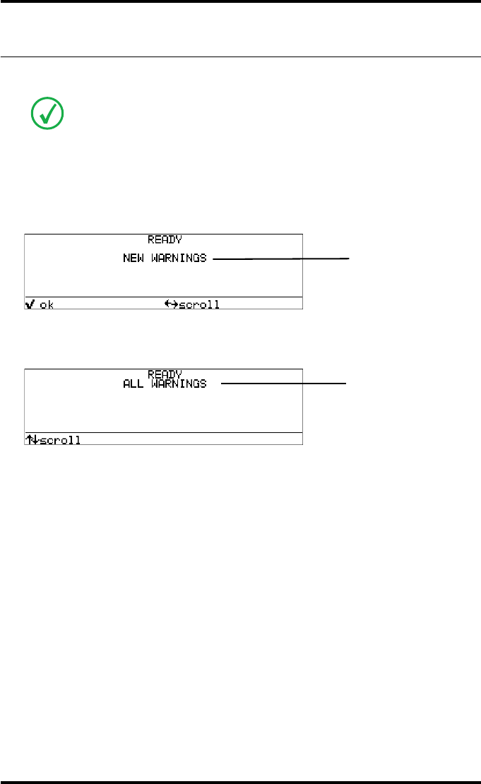
225
2900H EN 20071108 Troubleshooting
DRYSTAR 5500/5503 REFERENCE MANUAL
Warning messages
This section will inform you what to do when warning messages appear. A
warning message is displayed when an event has occurred that might
decrease image quality.
The Warning screen is displayed:
1Press the Confirm key to acknowledge the new warning condition.
The Ready screen will appear, holding all warning conditions:
2Contact your local service organization.
A warning message is different from an error message. A warning means that an
event occurred which might result in a decreased image quality. Printing is still
possible.
warning-message + code
warning-message + code
warning-message + code
Blinking
warning-message + code
warning-message + code
Blinking

226 2900H EN 20071108Troubleshooting
DRYSTAR 5500/5503 REFERENCE MANUAL

Equipment information
sheet
Appendix A

228 2900H EN 20071108Equipment information sheet
DRYSTAR 5500/5503 REFERENCE MANUAL
Specifications
Product description
Type of product Printer
Commercial name Drystar 5500, Drystar 5503
Original seller/manufacturer Agfa HealthCare N.V.
Labelling
TÜV-, cULus-Certification Mark,
CE-marking
CCC Mark
A#Sharp Mark
Dimensions
Dimensions (approx. values in cm)
• Unpacked: width 74, length 72,
height 142
• Packed: width 90, length 83,
height 160
Weight Drystar 5500/5503
•Unpacked: approx. 189.4kg /
192.4kg
• Packed: approx. 239 kg / 242 kg
Hard disk capacity 18 GByte or higher
Floppy disk capacity 2HD 1.44 Mbyte floppy disks
RAM memory 2x256 MB
Floppy disk container Four 2HD 1.44 Mbyte floppy disks

229
2900H EN 20071108 Equipment information sheet
DRYSTAR 5500/5503 REFERENCE MANUAL
Electrical connection
Operating voltage 100-120 V; 220-240 V AC
Rated current 4/2 A
Mains fuse protection
220-240 V operation 16/15 A slow blow, max.
100-120 V operation 16/15 A slow blow, max.
Mains frequency 50/60 Hz
Network connectivity
Ethernet / connectors RJ45 twisted pair for 10/100Base-TX;
Serial RS232 connection
Network protocols (TCP/IP services) FTP, Telnet, HTTP, SNMP, LPD
Image formats DICOM (Default)
TIFF
Power consumption - heat dissipation
During operation 450 W - 1620 kJ/h
In standby 200 W - 720 kJ/h
Peak power (absolute max. rating) 700 W - 2520 kJ/h
Protection against
Electrical shocks Class 1 (grounded)
Ingress of water IPXØ
Environmental conditions (operation)
Room temperature Between +15°C and +30°C
Relative humidity Between 20% and 75%
Note: Films may not become wet!
Atmospheric pressure 70 kPa - 106 kPa
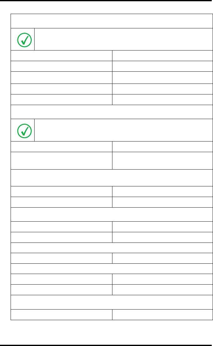
230 2900H EN 20071108Equipment information sheet
DRYSTAR 5500/5503 REFERENCE MANUAL
Environmental storage conditions
Climate conditions for storage are in accordance with EN60721-3-1-class 1K4.
Room temperature Between -25°C and 55°C (storage)
Relative humidity Between 10% and 100%
Absolute humidity Between 0.1 g/m3 and 35 g/m3
Rate of change of temperature 1°C/min
Atmospheric pressure 70 kPa - 106 kPa
Environmental transport conditions
Climate conditions for transport are in accordance with
EN60721-3-2-class 2K4.
Temperature Between -40°C and 70°C (transport)
Relative humidity not combined with
rapid temperature changes 95% at +45°C
Total acoustic A-weighted noise power (method of measurement in accordance
with ISO 3746:1995)
During operation 67 dB (=6.7B)
During stand-by 57 dB (=5.7B)
Consumables
DRYSTAR DT 2 B and DRYSTAR DT 2 C 8x10” up to 14x17” film sizes
DRYSTAR DT 2 Mammo (optional) 8x10”, 10x12” and 11x14” film sizes
Film throughput
14x17” > 100/h
Access time
1 film 14x17” Max. 90 sec.
4 films 14x17” Max. 200 sec.
Print technology
Direct thermal printing

231
2900H EN 20071108 Equipment information sheet
DRYSTAR 5500/5503 REFERENCE MANUAL
Reliability
Estimated product life
(if regularly serviced and maintained
according to Agfa instructions)
> 5 years and > 150,000 films
Service interventions Max. 2 interventions / 3 years
Earthquake (standard) Meets the CA requirements
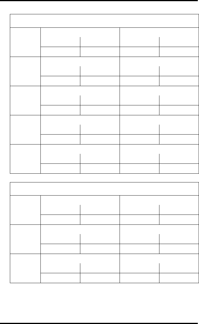
232 2900H EN 20071108Equipment information sheet
DRYSTAR 5500/5503 REFERENCE MANUAL
Imaging Array - Diagnostic area - General radiography
8x10” 8” dimensions 10” dimensions
pixels mm pixels mm
3852 192,6 4880 244
10x12” 10” dimensions 12” dimensions
pixels mm pixels mm
4880 244 5860 293
11x14” 11” dimensions 14” dimensions
pixels mm pixels mm
5376 268,8 6922 346,1
14x14” 14” dimensions 14” dimensions
pixels mm pixels mm
6882 344,1 6882 344,1
14x17” 14” dimensions 17” dimensions
pixels mm pixels mm
6922 346,1 8368 418,4
Imaging Array - Diagnostic area - Mammography (optional)
8x10” 8” dimensions 10” dimensions
pixels mm pixels mm
3828 191,4 4958 247,9
10x12” 10” dimensions 12” dimensions
pixels mm pixels mm
4892 244,6 5810 290,5
11x14” 11” dimensions 14” dimensions
pixels mm pixels mm
5376 268,8 6922 346,1

233
2900H EN 20071108 Equipment information sheet
DRYSTAR 5500/5503 REFERENCE MANUAL
Viewing the System info area on a film
General radiography applications
On the top right corner of each film, a “System info” area will be printed.
This info can only be read using a magnifying glass.
The System info area contains info about:
•The printer: (serial number, densitometer info, film counts, software
version, etc.),
•The controller (image source, date, time, etc.).
For more detailed information, refer to the Drystar 5500 Service
documentation.
Film
Diagnostic area
Clear border
Black border
System info area
Transport direction
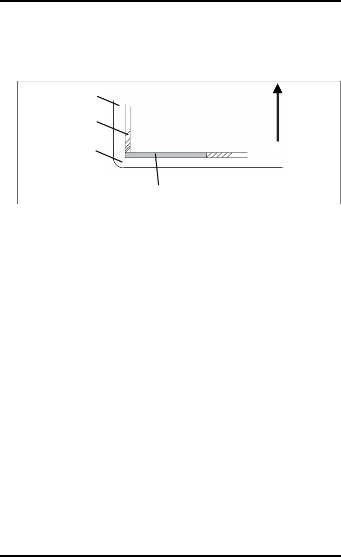
234 2900H EN 20071108Equipment information sheet
DRYSTAR 5500/5503 REFERENCE MANUAL
Mammography application (optional)
On the bottom left corner of each film, a “System info” area will be printed.
This info can only be read using a magnifying glass.
The System info area contains info about:
•The printer: (serial number, densitometer info, film counts, software
version, etc.),
•The controller (image source, date, time, etc.).
For more detailed information, refer to the Drystar 5500 Service
documentation.
Clear border
Diagnostic area
Film
Black border
System info area
Transport direction
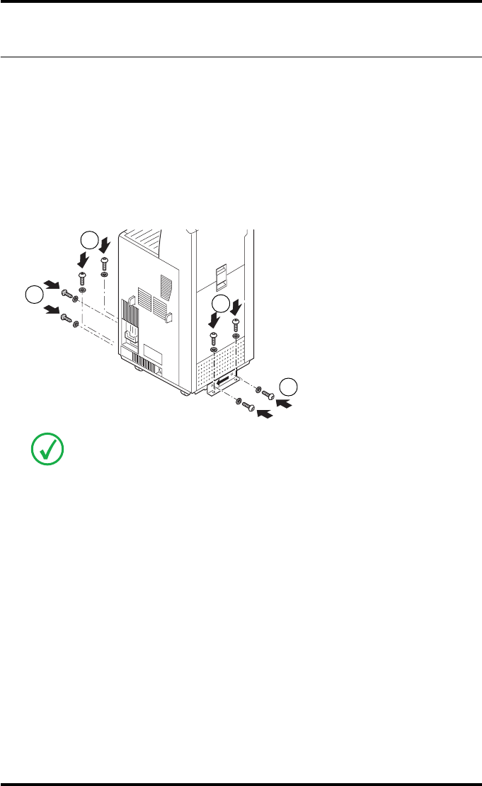
235
2900H EN 20071108 Equipment information sheet
DRYSTAR 5500/5503 REFERENCE MANUAL
Options and accessories
Mobile installation kit
The default installation kit allows you to use the Drystar 5500 (Mammo
inclusive) in mobile applications (e.g. a van), or in unstable environments.
Safe transportation is ensured by two fixation bars that lock the Drystar 5500
to its location (see illustration below). The fixation bars are included in the
default installation kit.
Mammography application
The Drystar 5500 can be used for printing mammography application films.
For this option, a license has to be activated by an Agfa service technician.
The feature comes with a QC procedure that complies with the
Mammography Quality Standards Act (MQSA) of the FDA. For more
information, refer to ‘Quality control for mammography application
(DT 2 Mammo) (optional)’ on page 153.
Contact your local service organization for more information.
For more information, refer to the “Remove Drystar 5500 from pallet” instructions
of the Drystar 5500 Plug & Play Installation manual (document 2903I or 2903J).
1
2
1
2

236 2900H EN 20071108Equipment information sheet
DRYSTAR 5500/5503 REFERENCE MANUAL
Connectivity
Drystar 5500-5503 must only be used in combination with other equipment or
components if these are expressly recognized by Agfa as compatible. A list of
such equipment and components is available from Agfa service on request.
Changes or additions to the equipment must only be carried out by persons
authorized to do so by Agfa. Such changes must comply with best engineering
practice and all applicable laws and regulations that have the force of law
within the jurisdiction of the hospital.
Drystar 5500-5503 is a Dicom printer and can therefore be connected to Agfa
equipment and all modalities supporting Dicom. Although, to ensure optimal
operation and image quality, Agfa has made the effort to test and release the
Drystar 5500-5503 with most of modalities on the market. For the complete list
or if you want to check on a specific modality, contact your Agfa representative.

Drystar media
density response data
Appendix B

238 2900H EN 20071108Drystar media density response data
DRYSTAR 5500/5503 REFERENCE MANUAL
DRYSTAR DT 2 B
dens. MacBeth
TR-924
Gretag
D200-2
X-rite
301
X-rite
310
X-rite
331
X-rite
341
0% 0.22 0,18 0.18 0,24 0.19 0.19
10% 0,51 0,48 0,48 0,54 0,49 0,49
20% 0,80 0,76 0,76 0,83 0,78 0,77
30% 1,09 1,05 1,06 1,13 1,08 1,07
40% 1,37 1,32 1,33 1,42 1,36 1,35
50% 1,67 1,62 1,62 1,72 1,65 1,64
60% 1,96 1,92 1,91 2,02 1,95 1,94
70% 2,25 2,20 2,19 2,31 2,23 2,23
80% 2,55 2,50 2,48 2,61 2,53 2,53
90% 2,83 2,79 2,76 2,90 2,81 2,81
100% 3,11 3,08 3,05 3,20 3,11 3,10
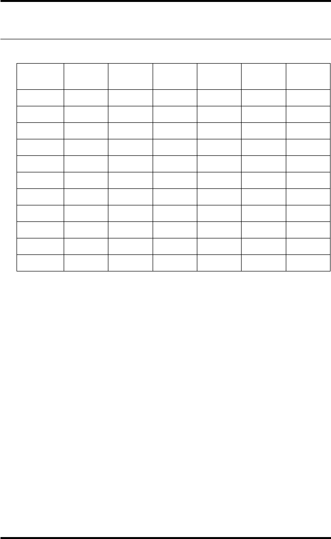
239
2900H EN 20071108 Drystar media density response data
DRYSTAR 5500/5503 REFERENCE MANUAL
DRYSTAR DT 2 C
dens. MacBeth
TR-924
Gretag
D200-2
X-rite
301
X-rite
310
X-rite
331
X-rite
341
0% 0,11 0,09 0,08 0,10 0,08 0,08
10% 0,39 0,38 0,36 0,39 0,38 0,37
20% 0,68 0,66 0,65 0,68 0,67 0,66
30% 0,96 0,94 0,93 0,97 0,95 0,94
40% 1,25 1,21 1,20 1,26 1,22 1,22
50% 1,52 1,49 1,47 1,55 1,50 1,50
60% 1,81 1,78 1,75 1,84 1,79 1,78
70% 2,09 2,06 2,03 2,13 2,07 2,07
80% 2,37 2,33 2,31 2,42 2,35 2,35
90% 2,65 2,62 2,59 2,71 2,63 2,63
100% 2,94 2,91 2,88 3,00 2,92 2,92
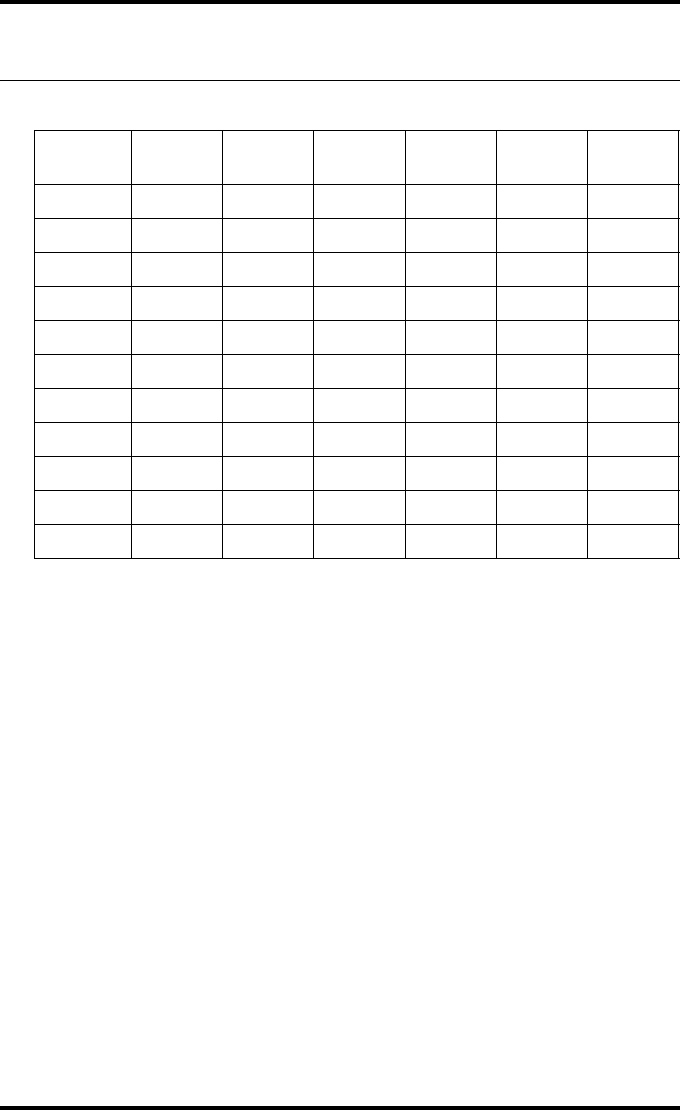
240 2900H EN 20071108Drystar media density response data
DRYSTAR 5500/5503 REFERENCE MANUAL
DRYSTAR DT 2 Mammo (optional)
dens. MacBeth
TR-924
Gretag
D200-2
X-rite
301
X-rite
310
X-rite
331
X-rite
341
0% 0,22 0,18 0,20 0,22 0,18 0,19
10% 0,57 0,52 0,54 0,58 0,52 0,54
20% 0,91 0,86 0,88 0,94 0,86 0,88
30% 1,25 1,19 1,20 1,29 1,19 1,21
40% 1,60 1,54 1,54 1,65 1,54 1,55
50% 1,94 1,88 1,88 2,01 1,88 1,89
60% 2,28 2,21 2,20 2,36 2,21 2,22
70% 2,62 2,56 2,54 2,72 2,55 2,56
80% 2,97 2,90 2,88 3,08 2,89 2,90
90% 3,32 3,24 3,21 3,44 3,23 3,25
100% 3,66 3,59 3,55 3,80 3,58 3,59

Quality Control Charts
Appendix C
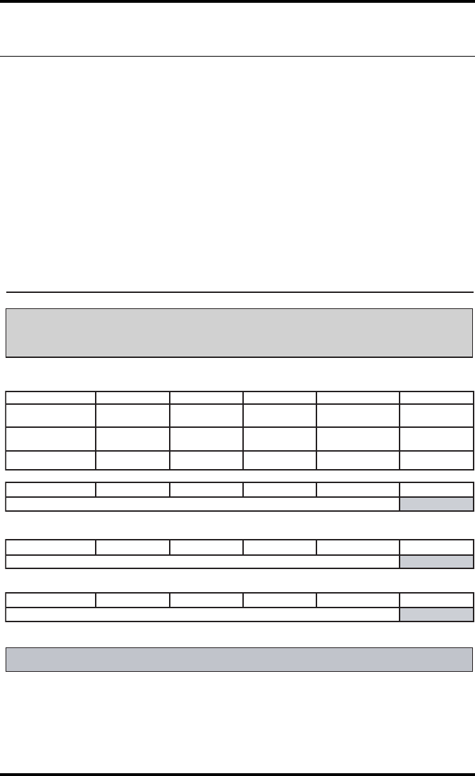
242 2900H EN 20071108Quality Control Charts
DRYSTAR 5500/5503 REFERENCE MANUAL
Charts for general radiography QC
Drystar 5500/5503: Determination of Operating Levels
Imager Type: __________ Serial #: _________________ Date ____________________
Film Type: ____________ Emulsion #: ______________
Densitometer: ________________ (default selection)
Day 1 Day 2 Day 3 Day 4 Day 5
Month
Day
Initials
Low Density
Average of 5 Values = calculated reference ìLow Densityî level
Mid Density
Average of 5 Values = calculated reference "Mid Density" level
High Density
Average of 5 Values = calculated reference ìHigh Densityî level
Step 1: Print QC Test images on five consecutive days. Record the optical densities
measurements in the tables below. After five days, average the values to determine
the reference levels for each of the parameters.
Step 2: Copy the calculated reference levels to Charts 2A/B ('Daily Density Control Chart')
General radiography applications
Input Tray: _______________
Quality Control for Chart 1
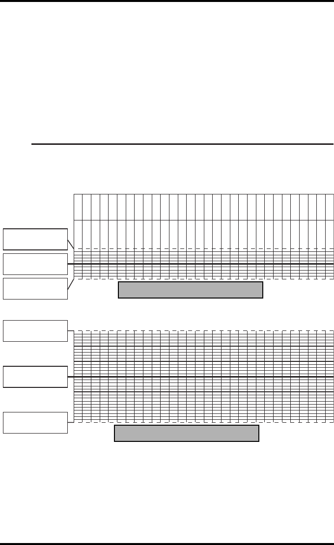
243
2900H EN 20071108 Quality Control Charts
DRYSTAR 5500/5503 REFERENCE MANUAL
Drystar 5500/5503 Daily Density
Control Chart
Imager Type: __________ Serial #: _____________ Film Type:____________ Emul #:__________
_
Densitometer Internal: ____________ (default selection)
Date:
Initials:
Low Density
Mid Density
Upper Control limit =
+0.05
Calculated Reference
Low Density Level
Lower Control Limit =
-0.05
Upper Control limit =
+0.15
Calculated Reference
Mid Density Level
Lower Control Limit =
-0.15
General radiography applications
Input Tray: ________
Quality Control for
Chart 2A
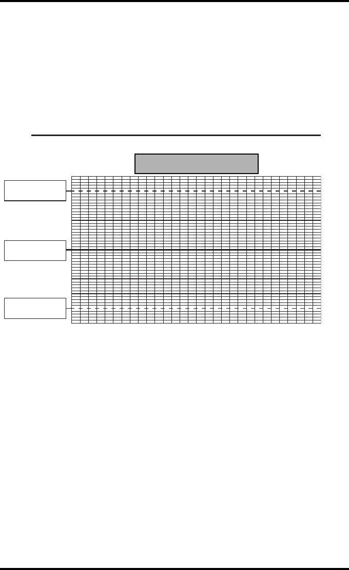
244 2900H EN 20071108Quality Control Charts
DRYSTAR 5500/5503 REFERENCE MANUAL
Drystar 5500/5503 Daily Density
Control Chart
Imager
Type: __________ Serial #: _____________ Film Type:____________ Emul #:__________
_
Densitometer Internal: _____________ (default selection)
High Density
Upper Control limit =
+0.20
Lower Control Limit =
-0.20
Calculated Reference
High Density Level
General radiography applications
Input Tray: ________
Quality Control for Chart 2B
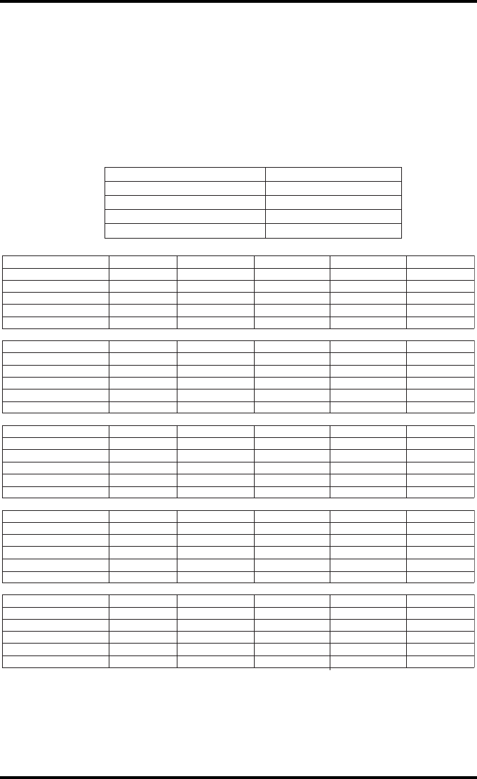
245
2900H EN 20071108 Quality Control Charts
DRYSTAR 5500/5503 REFERENCE MANUAL
Drystar 5500/5503 Artifacts and Spatial Resolution
Control Chart
Test Frequency: Weekly Drystar 5500/5503 Serial # _____________
Initial Reference Test Date
Initial Reference Artifacts
Initial Reference Dot Visibility
Initial Reference Low Contrast
Month
Day
Artifacts
Visibility of all Dots
Month
Day
Artifacts
Visibility of all Dots
Month
Day
Artifacts
Visibility of all Dots
Month
Day
Artifacts
Visibility of all Dots
Month
Day
Artifacts
Visibility of all Dots
Low Contrast Visibility
Low Contrast Visibility
Low Contrast Visibility
Low Contrast Visibility
Low Contrast Visibility
General radiography applications
Input Tray: ____________
Quality Control for
Chart 3
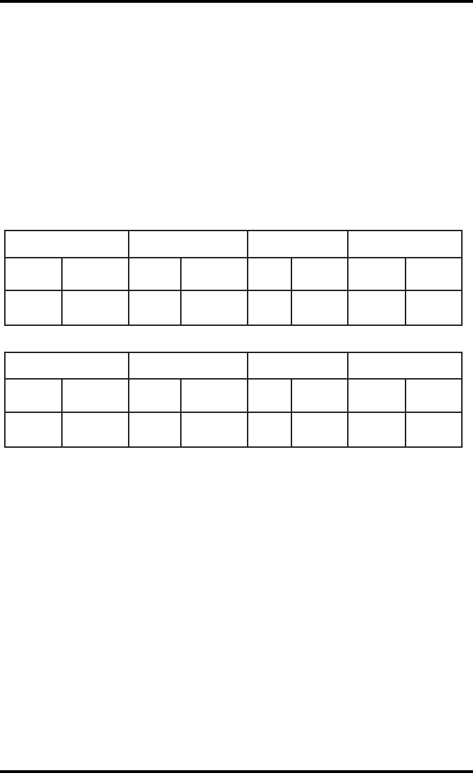
246 2900H EN 20071108Quality Control Charts
DRYSTAR 5500/5503 REFERENCE MANUAL
Drystar 5500/5503 Geometric Consistency
Control Chart
Test Frequency: Annually or as required Drystar 5500/5503 Serial # _____________
_
Reference Dimensions
Date:
Measured Dimensions
Date:
Consistency Aspect Ratio
Aref A: A/Aref A/B
Bref B: B/Bref
Reference Dimensions
Date:
Measured Dimensions
Date:
Consistency Aspect Ratio
Aref A: A/Aref A/B
Bref B: B/Bref
General radiography applications
Input Tray: _______________________
Quality Control for Chart 4
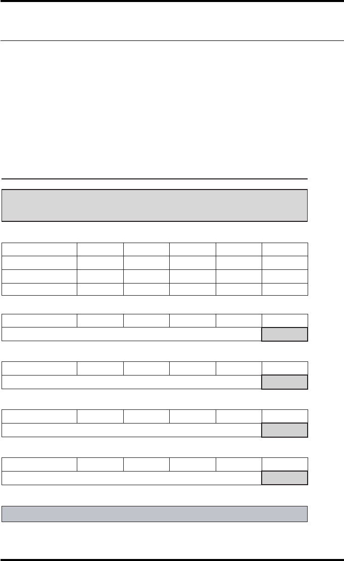
247
2900H EN 20071108 Quality Control Charts
DRYSTAR 5500/5503 REFERENCE MANUAL
Charts for mammography QC (optional)
Drystar 5500/5503 : Determination of Operating Levels
Imager Type: __________ Serial #: _________________ Date ____________________
Film Type: ____________ Emulsion #: ______________
Densitometer
: _________________ (default selection)
Step 1: Print QC Test images on five consecutive days. Record the optical densities
measurements in the tables below. After five days, average the values to determine
the reference levels for each of the parameters.
Mammography applications
Month
Day 1 Day 2 Day 3 Day 4 Day 5
Date
Initials
Average of 5 values = calculated reference "Base + Fog" level
Base + Fog
Average of 5 values = calculated reference "Low Density" level
Low Density
Average of 5 values = calculated reference "Mid Density" level
Mid Density
Average of 5 values = calculated reference "High Density" level
High Density
Step 2: Copy the calculated reference levels to Charts 2A/B ('Daily Density Control Chart')
Input Tray: _______________
Quality Control for Chart 1
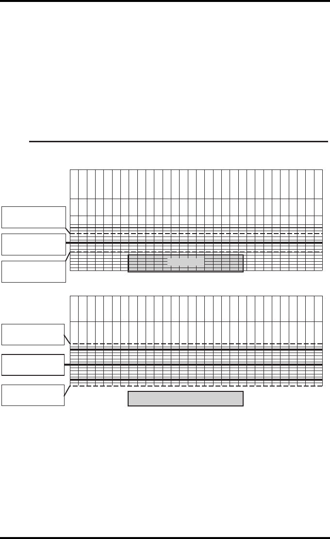
248 2900H EN 20071108Quality Control Charts
DRYSTAR 5500/5503 REFERENCE MANUAL
Drystar 5500/5503 Daily Density
Control Chart
Imager Type: __________ Serial #: _____________ Film Type:____________ Emul #:__________
_
Densitometer: _________________ (default selection)
Mammography applications
Input Tray: ________
Quality Control for Chart 2A
Date:
Initials:
Upper Control limit =
+0.03
Calculated Reference
Base + Fog Level
Base + Fog
Low Density
Lower Control limit =
-0.03
Date:
Initials:
Upper Control limit =
+0.07
Calculated Reference
Low Density Level
Lower Control Limit =
-0.07
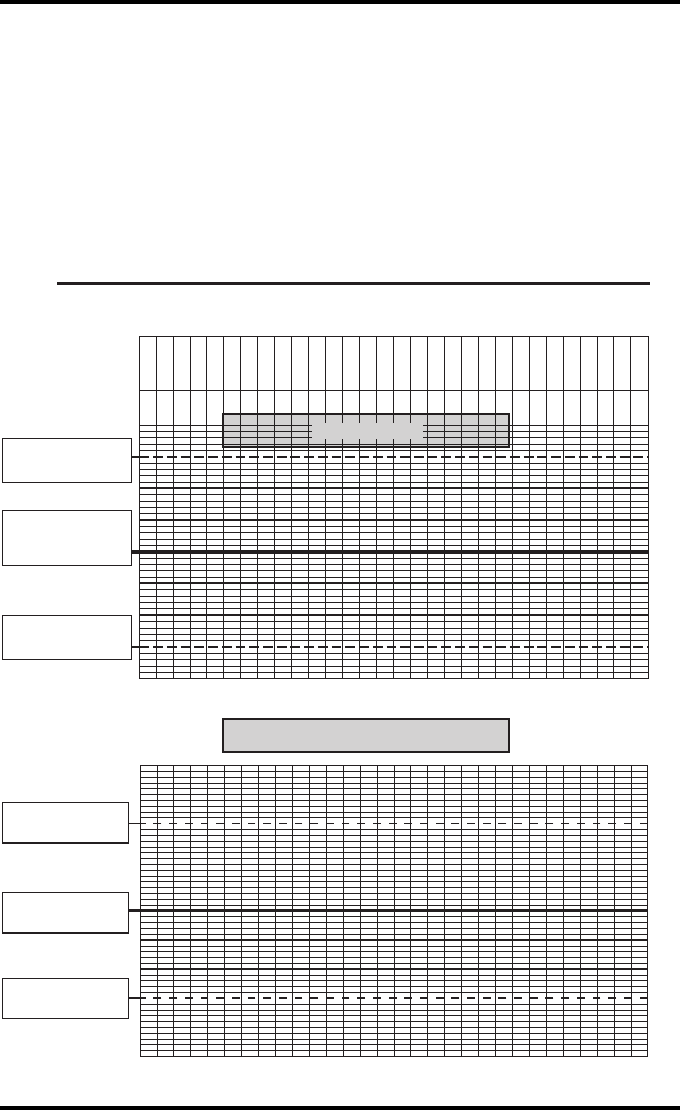
249
2900H EN 20071108 Quality Control Charts
DRYSTAR 5500/5503 REFERENCE MANUAL
Drystar 5500/5503 Daily Density
Control Chart
Imager
Type: __________ Serial #: _____________ Film Type:____________ Emul #:__________
_
Densitometer: _________________ (default selection)
Mammography applications
Input Tray: ________
Quality Control for Chart 2B
Date:
Initials:
Upper Control limit =
+0.15
Lower Control limit =
-0.15
Calculated Reference
Mid Density Level
Mid Density
High Density
Upper Control limit =
+0.15
Lower Control Limit =
-0.15
Calculated Reference
High Density Level
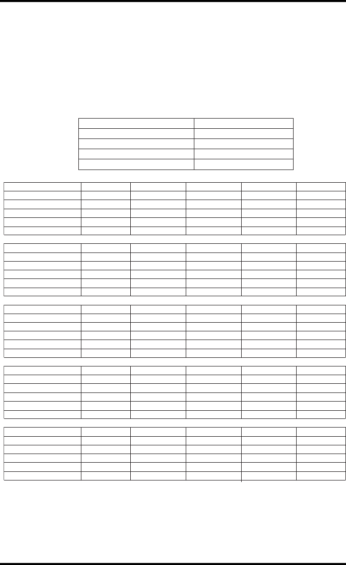
250 2900H EN 20071108Quality Control Charts
DRYSTAR 5500/5503 REFERENCE MANUAL
Drystar 5500/5503 Artifacts and Spatial Resolution
Control Chart
Test Frequency: Weekly Drystar 5500/5503 Serial # _____________
Initial Reference Test Date
Initial Reference Artifacts
Initial Reference Dot Visibility
Initial Reference Low Contrast
Month
Day
Artifacts
Visibility of all Dots
Month
Day
Artifacts
Visibility of all Dots
Month
Day
Artifacts
Visibility of all Dots
Month
Day
Artifacts
Visibility of all Dots
Month
Day
Artifacts
Visibility of all Dots
Low Contrast Visibility
Low Contrast Visibility
Low Contrast Visibility
Low Contrast Visibility
Low Contrast Visibility
Mammography applications
Input Tray: ____________
Quality Control for
Chart 3
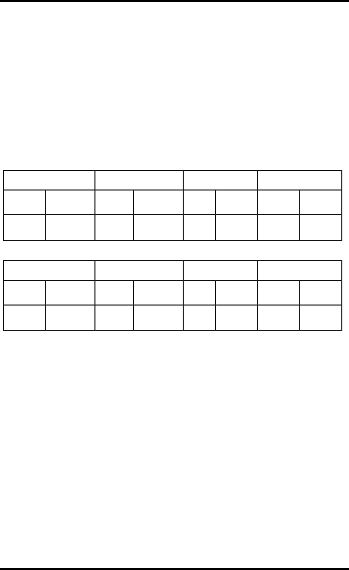
251
2900H EN 20071108 Quality Control Charts
DRYSTAR 5500/5503 REFERENCE MANUAL
Drystar 5500/5503 Geometric Consistency
Control Chart
Test Frequency: Annually or as required Drystar 5500/5503 Serial # __________
_
Reference Dimensions
Date:
Measured Dimensions
Date:
Consistency Aspect Ratio
A
ref
A: A/A
ref
A/B
B
ref
B: B/B
ref
Reference Dimensions
Date:
Measured Dimensions
Date:
Consistency Aspect Ratio
A
ref
A: A/A
ref
A/B
B
ref
B: B/B
ref
Mammography applications
Input Tray: ______________________
Quality Control for Chart 4

252 2900H EN 20071108Quality Control Charts
DRYSTAR 5500/5503 REFERENCE MANUAL

Remarks for HF-emission
and immunity
Appendix D

254 2900H EN 20071108Remarks for HF-emission and immunity
DRYSTAR 5500/5503 REFERENCE MANUAL
Remarks for HF-emission and immunity
This device is intended for operation in the electromagnetic
environment given below. The user of the device should ensure
that it is used in such an environment.
This device was tested for a normal hospital environment as described above.
Nevertheless the HF-emission and immunity can be influenced by connected
data cables depending on length and the manner of installation.
Transmission Measurements Agreement Electromagnetic Environment
Guidelines
High frequency transmissions in
accordance with CISPR 11 Group 1
The device uses high frequency energy
exclusively for its internal functions. For this
reason, its high frequency transmission is
very low and it is improbable that
neighboring electronic equipment will be
disrupted.
High frequency transmissions in
accordance with CISPR 11 Class A The device is intended for use in an
environment that do not include living areas
and in areas directly connected to a public
supply network that also supplies buildings
that are used for domestic purposes
Excess oscillations in accordance
with IEC 61000-3-2 Class A
Voltage fluctuations / flickering in
accordance with IEC 61000-3-3 Fulfilled

255
2900H EN 20071108 Remarks for HF-emission and immunity
DRYSTAR 5500/5503 REFERENCE MANUAL
This device is intended for operation in the electromagnetic
environment given below. The user of the device should ensure
that it is used in such an environment.
Resistance to
Jamming Test
IEC 60601
Test Level
Level of
Agreement
Electromagnetic
Environment Guidelines
Discharge of
static electricity
in accordance
with IEC 61000-
4-2
+ 4 kV contact
discharge
+ 8 kV air
discharge
+ 6 kV contact
discharge
+ 8 kV air
discharge
Floors should consist of
wood, concrete or ceramic
tiles. The relative humidity
must be at least 30%, if the
floor is made of synthetic
material.
Fast transient
electrical
disturbance
variables / bursts
in accordance
with IEC 61000-
4-4
+ 1 kV mains
+ 0,5 kV data
lines
+ 1 kV mains
+ 0,5 kV data
lines
The quality of the voltage
supplied should correspond
to a typical commercial or
clinical environment.
Impulse voltages
(surges) in
accordance with
IEC 61000-4-5
+ 1 kV push-pull
voltage
+ 2 kV common
mode voltage
+ 1 kV push-pull
voltage
+ 2 kV common
mode voltage
The quality of the voltage
supplied should correspond to
that of a typical commercial or
clinical environment.
Voltage
breakthroughs,
short term
interruptions and
variations in the
voltage supplied in
accordance with
IEC 61000-4-11
•< 5% U
r (> 95%
breakthrough of
Ur) for ½ period
•40% U
r (> 60%
breakthrough of
Ur) for 5 periods
•70% U
r (30%
breakthrough of
Ur) for 25 periods
•< 5% U
r (95%
breakthrough of
Ur) for 5 s
•< 5% U
r (> 95%
breakthrough of
Ur) for ½ period
•40% U
r (> 60%
breakthrough of
Ur) for 5 periods
•70% U
r (30%
breakthrough of
Ur) for 25 periods
•< 5% U
r (95%
breakthrough of
Ur) for 5 s
The quality of the voltage supply
should correspond to that of a
typical commercial or clinical
environment.
If the user wants the device to
work continuously, even when
the energy supply is interrupted,
it is recommended to use an
energy supply free of
interruptions or a battery.
Magnetic field at
the supply
frequency (50/60
Hz) in accordance
with IEC 61000-4-8
3 A/m 10 A/m
Magnetic field at the network
frequency should correspond to
the typical values as they are in a
commercial and clinical
environment.
•REMARK : U
r is the alternating current in the network before the application of the test level.
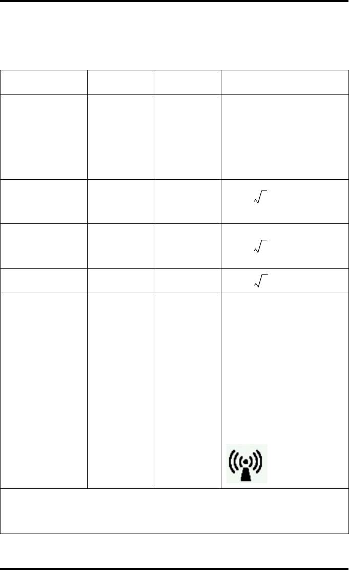
256 2900H EN 20071108Remarks for HF-emission and immunity
DRYSTAR 5500/5503 REFERENCE MANUAL
This device is intended for operation in the electromagnetic
environment given below. The user of the device should ensure
that it is used in such an environment.
Tests of Resistance
to Disruption
IEC 60601
Test Level
Level of
Agreement Electromagnetic Environment
Use portable and mobile radio sets
at a safe distance from the device
(including the leads) not closer
than the recommended protective
distance, which is calculated
according to the equation suitable
for the transmission frequency.
Recommended protective distance:
Conducted high
frequency disturbance
variables in accordance
with IEC 61000-4-6
3 Veff
150 kHz
to 80 MHz
10 Veff d = 1.2
Radiated high
frequency disturbance
variables in accordance
with IEC 61000-4-3
3 V/m
80 MHz
to 2.5 GHz
10 V/m d = 1.2 80 MHz to 800 MHz
d = 2.3 800 MHz to 2.5 GHz
With P as the rated power of the
transmitter in watts (W) in
accordance with the manufacturer
information on the transmitter and
d as the recommended protective
distance in metres (m).
The field strength of stationary
radio transmitters is lower than the
level of the agreementa at all
frequencies in accordance with an
on-site investigationb.
Disruptions are possible near
devices that carry the following
symbol:
• REMARK 1: The higher value will apply at 80 MHz and 800 MHz.
• REMARK 2: These Guidelines may not apply to all situations. The dispersion of
electromagnetic waves is influenced by absorption and reflections from buildings,
objects and people.
P
P
P

257
2900H EN 20071108 Remarks for HF-emission and immunity
DRYSTAR 5500/5503 REFERENCE MANUAL
a. The field strength of stationary transmitters, such as base stations of radio telephones, mobile
broadcasts for rural areas, amateur stations, and AM and FM radio transmitters, cannot be
precisely predetermined theoretically. An investigation of the location is recommended, to
ascertain the electromagnetic environment as a result of stationary high frequency transmitters. If
the field strength of the device exceeds the level of agreement given above, the device must be
observed with regard to its normal operation at each place of use. In case of unusual performance
characteristics, it can be necessary to take additional measures, such as the re-orientation of the
device, for example.
b. The field strength will be lower than 3 V/m above the frequency range from 150 kHz to 80 MHz.
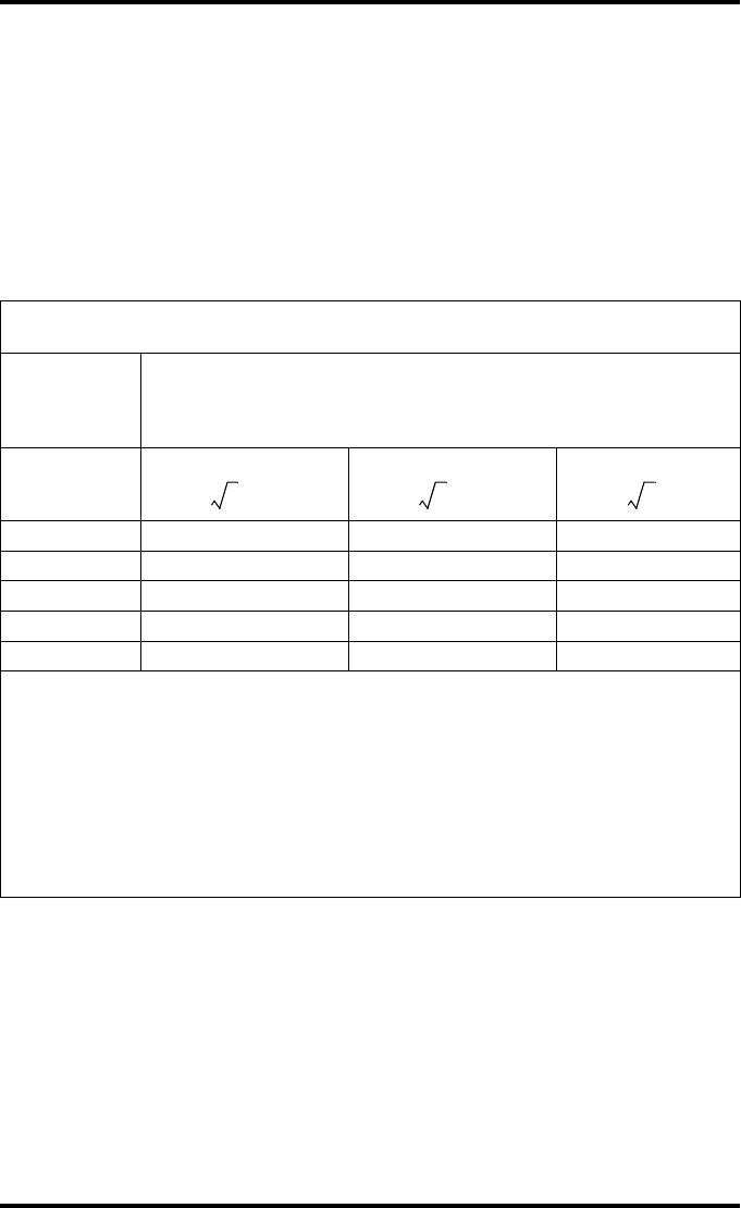
258 2900H EN 20071108Remarks for HF-emission and immunity
DRYSTAR 5500/5503 REFERENCE MANUAL
This device is intended for operation in an electromagnetic
environment in which the radiated high frequency disturbance
variables are monitored. The user of the device can help to
prevent electromagnetic disruptions by maintaining the
minimum distances between portable and mobile high frequency
communication equipment (transmitters) and the device as
recommended below, in accordance with the maximum output
power of the communications equipment.
Recommended Protective Distances between Portable and Mobile
High Frequency Communication Equipment and the Device
Rated Power of
the Transmitter
W
Protective Distance in accordance with Transmission Frequency
m
150 kHz to 80 MHz
d = 1.2
80 MHz to 800 MHz
d = 1.2
800 MHz to 2.5 GHz
d = 2.3
0.01 0.12 0.12 0.23
0.10.380.380.73
11.2 1.2 2.3
10 3.8 3.8 7.3
100121223
The distance can be determined through the equation for each respective column.
P is the rated power of the transmitter in watts (W) according to the manufacturer information on
the transmitter, only for transmitters where the rated power is not mentioned in the above table.
• REMARK 1 : An additional factor of 10/3 has been used to calculate the recommended protective
distance of transmitters in the frequency range from 80 MHz to 2.5 GHz, to reduce the probability
that mobile portable communication equipment unintentionally brought into the area of the
patients will lead to a disruption.
• REMARK 2 : These Guidelines may not be relevant in all situations. The dispersion of
electromagnetic waves is influenced by absorption and reflections from buildings, objects and
people.
P P P

Index
Chapter E

260 2900H EN 20071108Index
DRYSTAR 5500/5503 REFERENCE MANUAL
Index
A
A#Sharp label. See Labels
A#sharp technology ..........................11
Administrator mode...........................25
Attributing fixed IP address to remote PC
168
Audio signals ....................................28
B
Back-up of settings
how to make a back-up of the printer
settings on a floppy disk?...........105
Beeps. See Audio signals
Browser mode
configuration with crossed network
cable.........................................167
configuration with straight network
cable.........................................167
entering key-operator level.........174
entering operator level...............174
how to control the Drystar 5500 via
the browser? .............................165
how to set up a direct link?.........168
how to set up a link through a
network? ...................................172
how to start a remote session? ..173
C
Calibration
accessing..................................111
film calibration...........................112
overview of calibration functions.221
print head cleaning ....................115
print head profile calibration.......118
CCC. See Labels
CE. See Labels
Change settings menu
accessing....................................70
overview .....................................69
Components Drystar 5500...............178
Configuration network .....................183
Connections, checking.................... 197
Control charts.................................241
Control modes, local and remote .......26
Cooling.............................................36
Cooling down....................................36
cULus. See Labels
D
Default densitometer.........................93
Delete print job .................................42
Diagnostic area...............................232
Dimensions DS5500 .......................228
Display
data entry ...................................33
key-operator mode ...................... 32
messages ...................................31
operator mode ............................31
Domain name
how to change?...........................80
DRYSTAR......................................240
DT 2 B............................................238
DT 2 C............................................239
DT 2 Mammo..................................240
E
Electrical connection .......................229
Emergency priority............................41
Environmental conditions
operation ..................................229
storage ..................................... 230
transport ...................................230
Error messages
checking error messages...........196
checking floppy disk error messages
198
while printer starts up ................218
F
Film
DT2 B /DT2 C /DT 2 M ..........12, 44
formats ................................. 10, 44
how to change the film view?.......77

261 2900H EN 20071108Index
DRYSTAR 5500/5503 REFERENCE MANUAL
how to clear film jams? ..............199
identification problems...............214
quality problems........................220
Film calibration..................................91
Film format
changing film format of the tray ..180
Film jam
in the front section .....................203
in the input tray..........................200
in the output section ..................209
in the print section .....................205
possible locations ......................199
Floppy disk
back-up procedure ....................106
checking floppy disk error messages
198
printing files from a printer floppy102
restore procedure......................108
upgrading the software ..............121
Functional description Drysatr 5500.179
G
General image quality settings
activating the film calibration ........91
selecting the default densitometer 93
General settings
assignment modality - output tray.75
beep on empty tray......................76
date and time ..............................72
language.....................................73
sorter configuration......................74
H
HF-emission and immunity remarks.254
Hostname
how to change?...........................79
I
Icons ................................................29
Identification problems ....................214
Image quality
flowchart ...................................222
maintaining image quality ..........220
resolving image quality problems220
Image quality for general radiography
applications
calculated operating levels.144, 145
how to perform the quality control
procedures?..............................149
how to set the default values?....142
performing the Annual QC tests. 152
performing the daily QC test ......149
performing the Weekly QC tests 151
Image quality for the mammography
application
calculated operating levels.........157
how to establish the reference values
and verifying image quality ........154
Performing the Annual QC tests.164
Performing the daily QC test......161
Performing the Weekly QC tests 163
Spatial Resolution and Artifact Levels
and Low Contrast Visibility.........160
Image quality problem
low frequency banding...............223
sratches on film.........................224
white dots or lines in transport
direction....................................223
Image quality settings .................91, 94
Image quality settings for a modality
changing the interpolation............96
changing the maximum density....98
selecting a lookup table ...............94
Imaging array .................................232
Indicator LEDs
meaning of the LED signals.......195
Input tray settings
film view......................................77
Installation
using the install data-sets ..........121
using the installation wizard.......127
Interpolation
how to change the interpolation? .96
IP-address
how to attribute fixed IP-address to
remote PC? ..............................168
how to change the Printer IP-
address?.....................................81
how to change the Router IP-
address?.....................................84

262 2900H EN 20071108Index
DRYSTAR 5500/5503 REFERENCE MANUAL
J
Jams (how to solve?) ......................199
K
Key-operator functions
calibration .................................111
change settings ...........................69
installation.................................121
menu structure ............................57
overview .....................................56
print image................................100
restore configuration..................107
save configuration .....................105
show settings ..............................60
stop printing ................................59
Key-operator menu ...........................32
accessing....................................58
menu structure ............................57
Key-operator mode ...........................24
Keypad.............................................29
Keys
confirm key .................................29
delete key ...................................29
emergency key............................29
escape key..................................29
key-operator key .........................29
service key..................................29
L
Labels
A#Sharp......................................11
CCC ...........................................19
CE/TÜV/cULus............................19
RoHS..........................................16
LEDs
meaning of the LED signals .......195
Link between PC and Drystar 5500
direct link ..................................168
through a network......................172
Loading films ....................................46
checking the correct position........54
loading procedure........................50
when in ready state .....................49
when printing or calculating..........47
Lookup table
how to select another? ................94
M
Mammography
how to set the default values?....154
Maximum density
how to change?...........................98
Media density respons data....238, 239,
240
Modality
how to add? ................................87
how to remove? ..........................86
N
Net mask
how to change?...........................83
Network (DICOM)
adding a modality........................87
domain name ..............................80
hostname....................................79
netmask......................................83
printer AE-title .............................78
printer IP-address........................81
removing a modality .................... 86
router IP-address ........................84
Network connectivity .......................229
O
Operating modes
administrator mode .....................25
key-operator mode ...................... 24
operator mode ............................24
service mode .............................. 24
specialist mode ...........................25
Operator functions
assigning emergency priority .......41
deleting print jobs........................ 42
loading films................................46
managing the print queue ............39
overview .....................................38

263 2900H EN 20071108Index
DRYSTAR 5500/5503 REFERENCE MANUAL
Operator mode..................................24
P
Power
button location.............................27
switching off ................................36
switching on ................................34
Power consumption.........................229
Print head
how to clean?............................115
Print head profile calibration
registration........................118, 120
starting......................................118
TPH profile........................119, 120
Print image,accessing .....................100
Print job, delete.................................42
Print queue.......................................39
Print queue, checking......................197
Printer AE-title
how to change?...........................78
Printer information
how to view? ...............................60
Printing files
from a printer floppy...................102
from hard disk ...........................101
how to stop?................................59
viewing system area..................233
Proxy settings
how to switch off?......................170
Q
Quality control
charts........................................241
Quality control for general radiography
applications (DT 1 B & DT 1 C)
calculated operating levels.144, 145
how to perform the quality control
procedures?..............................149
how to set the default values?....142
performing the Annual QC tests .152
performing the daily QC test ......149
performing the Weekly QC tests.151
Quality control for general radiography
applications (DT 2 B & DT 2 C)........141
Quality control for the mammography
application
calculated operating levels.........157
how to establish the reference values
and verifying image quality ........154
Performing the Annual QC tests.164
Performing the daily QC test......161
Performing the Weekly QC tests 163
Spatial Resolution and Artifact Levels
and Low Contrast Visibility.........160
Quality control for the mammography
application (DT 2 Mammo) ..............153
Quality problems.............................220
R
Remote PC
configuration with crossed network
cable ........................................167
configuration with straight network
cable ........................................167
Restoring settings
how to restore settings from a
diskette?...................................107
how to restore settings from a floppy
disk?.........................................107
RoHS label. See Labels
S
Safety
compliance .................................18
precautions .................................13
transport after installation ..........184
Security precautions .........................17
Service mode ...................................24
Specialist mode ................................25
Start-up errors ................................218
Status indicator
LED status..................................28
location.......................................27

264 2900H EN 20071108Index
DRYSTAR 5500/5503 REFERENCE MANUAL
Stop printing .....................................59
Switching off .....................................36
Switching off proxy settings of the
browser ..........................................170
Switching on .....................................34
T
Test films
registration................................120
TPH profile................................120
Transport. See Safety
Tray, changing film format ...............180
Troubleshooting checklist ................194
TÜV. See Labels
U
Upgrading the software ...................121
User interface ...................................27
audio signals...............................28
control buttons ............................28
control panel ...............................29
display ........................................31
keypad........................................29
overview .....................................27
status indicator LED ....................28
W
Warning messages .........................225

265
2900H EN 20071108 Index
DRYSTAR 5500/5503 REFERENCE MANUAL

0413
Printed in Belgium
Published by Agfa HealthCare N.V., B-2640 Mortsel-Belgium
2900H EN 20071108