Agfa NV 5366 Drystar 5302/xxx tabletop printer User Manual Print Composer Module for CR Quality System 3 0
Agfa Gevaert N V Drystar 5302/xxx tabletop printer Print Composer Module for CR Quality System 3 0
Agfa NV >
Contents
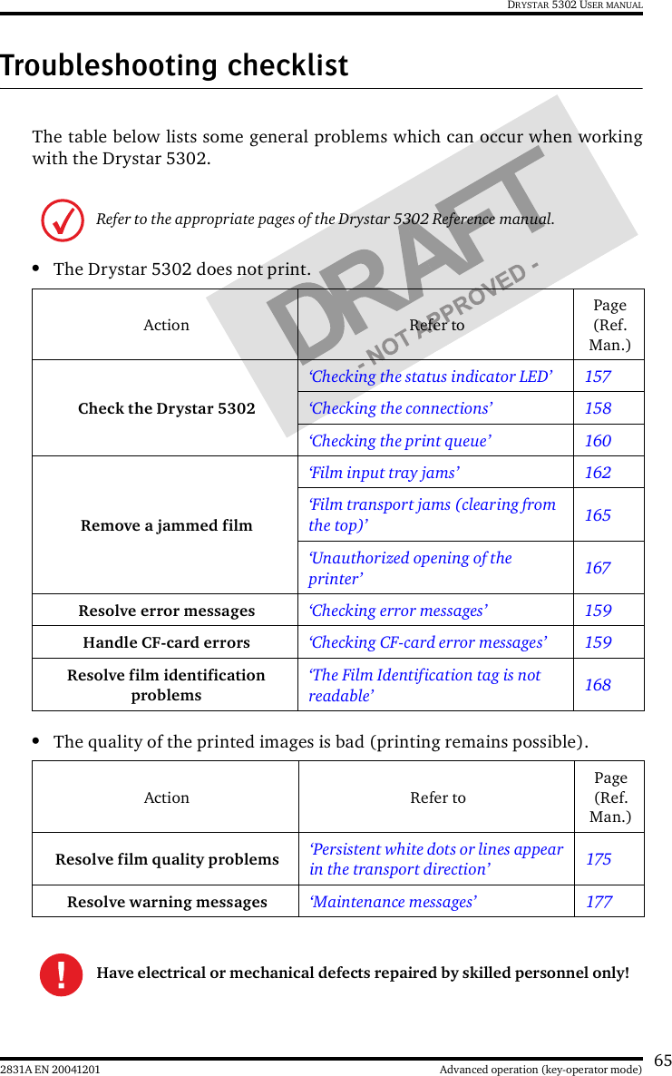
- 1. User manual part 1
- 2. User manual part 2
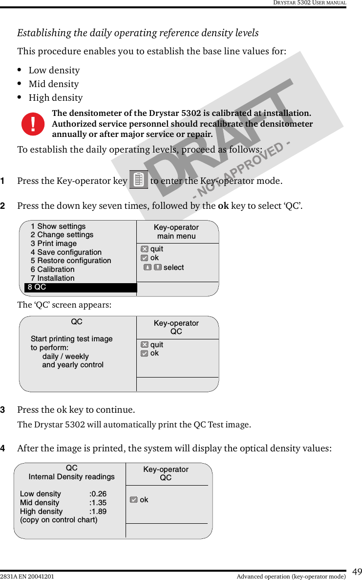
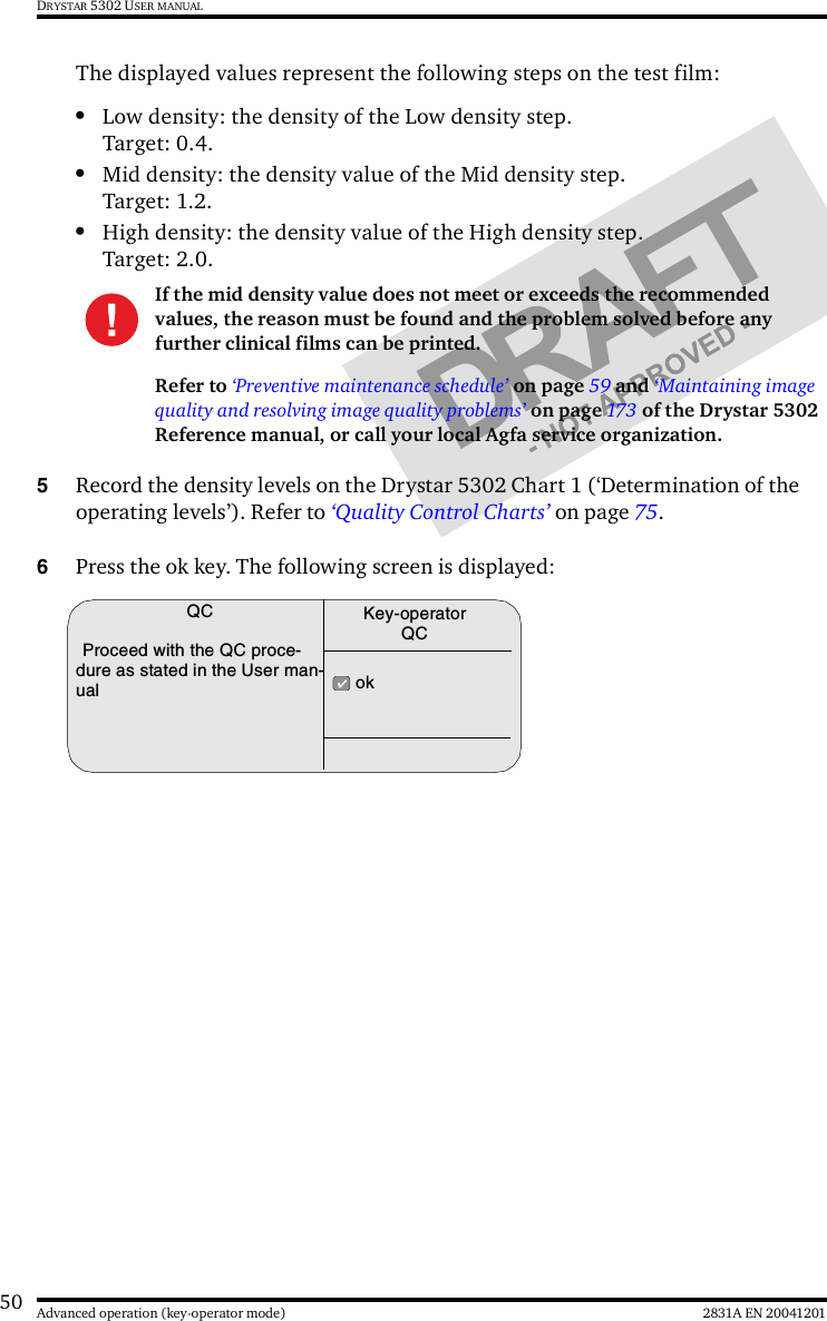
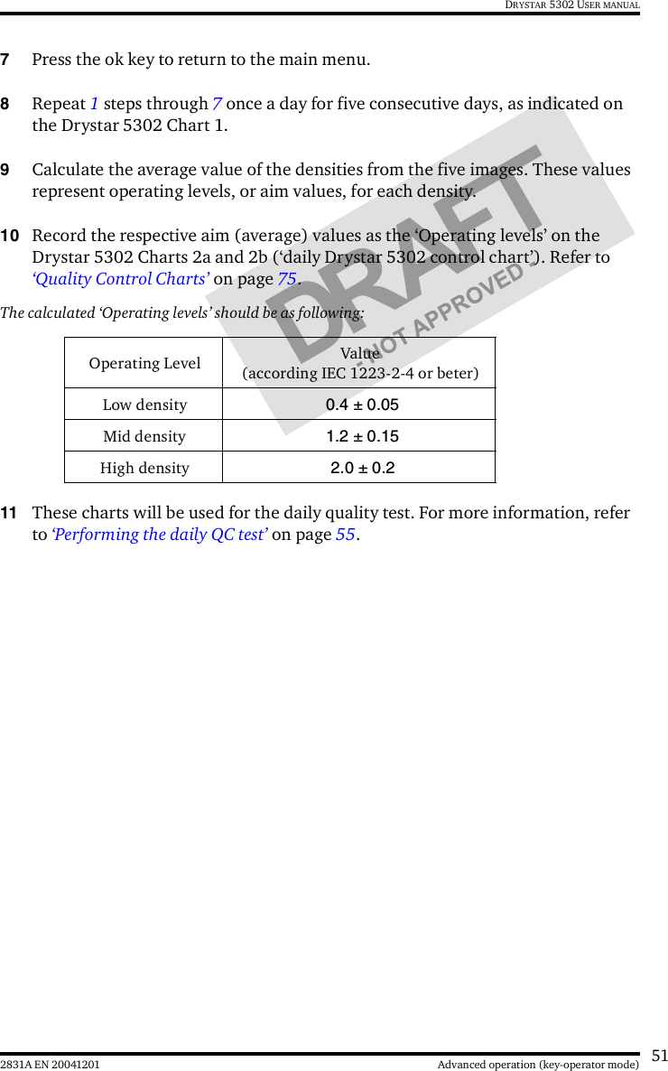
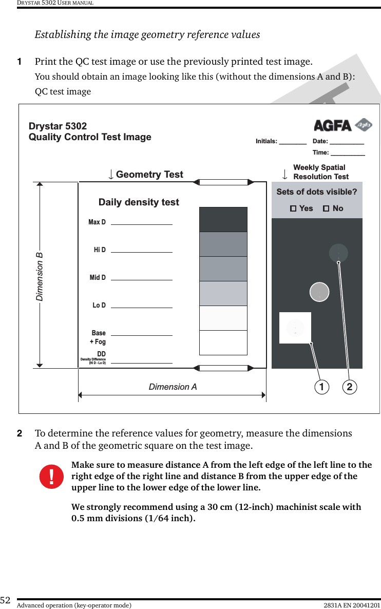
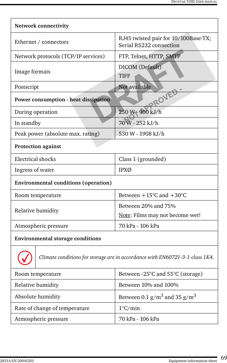
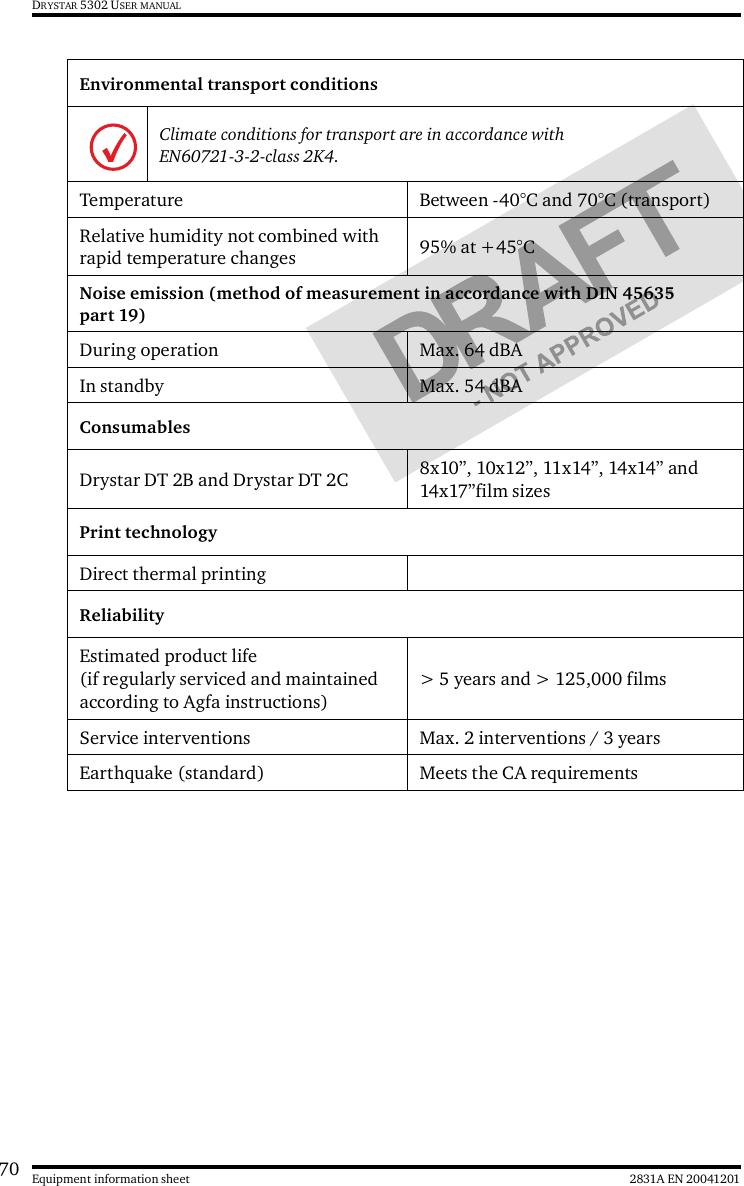
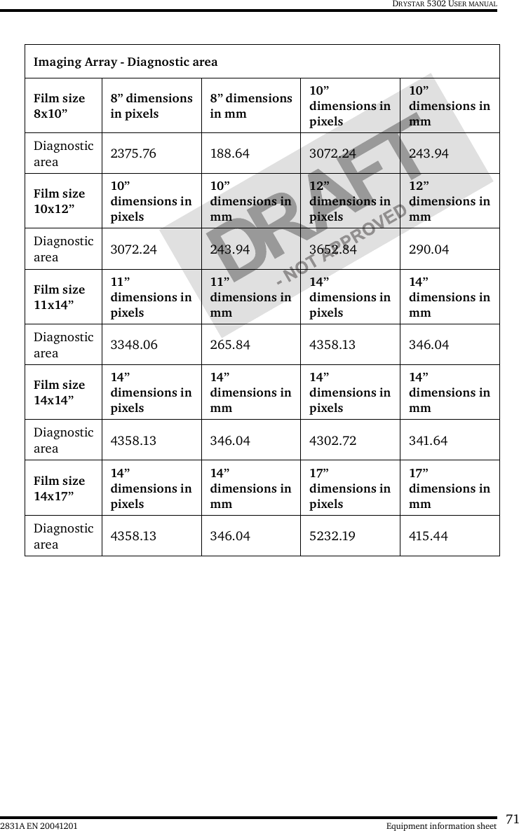
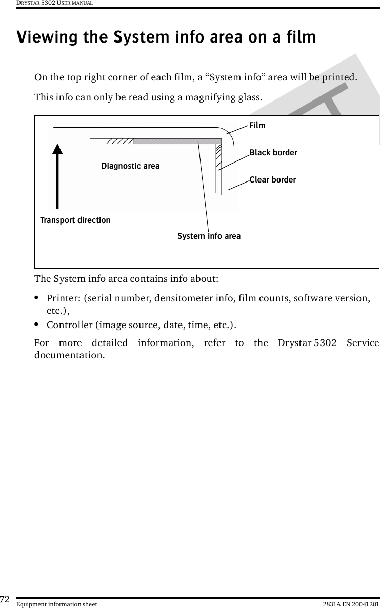
User manual part 2