Agfa NV 5366 Drystar 5302/xxx tabletop printer User Manual Print Composer Module for CR Quality System 3 0
Agfa Gevaert N V Drystar 5302/xxx tabletop printer Print Composer Module for CR Quality System 3 0
Agfa NV >
Contents
- 1. User manual part 1
- 2. User manual part 2
User manual part 2

Advanced operation
(key-operator mode)
This chapter gives an overview of functions for the advanced
user:
!Overview of key-operator functions
!Quality Control
!Preventive maintenance schedule
!Cleaning the exterior
!Cleaning the print head
!Troubleshooting checklist
Chapter 3
46 2831A EN 20041201Advanced operation (key-operator mode)
DRYSTAR 5302 USER MANUAL
Overview of key-operator functions
The key-operator menus make it possible to use the Drystar 5302 advanced
functions.
For general information on the key functions of the Drystar 5302, refer to ‘The
user interface’ on page 20.
Overview
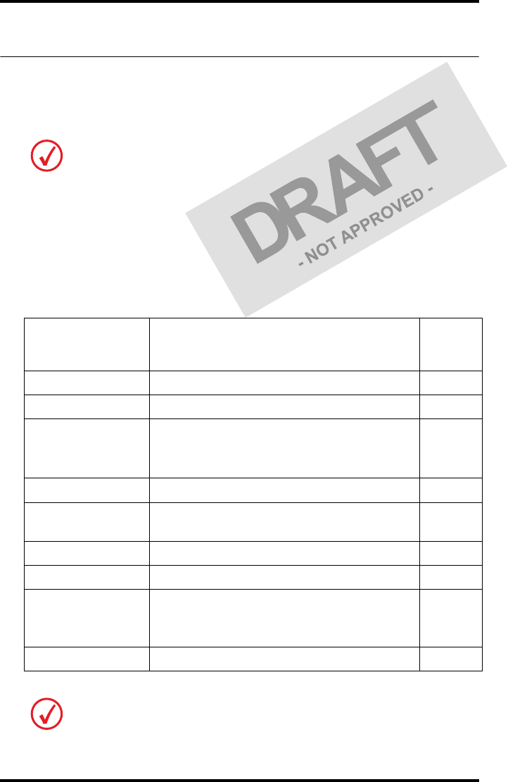
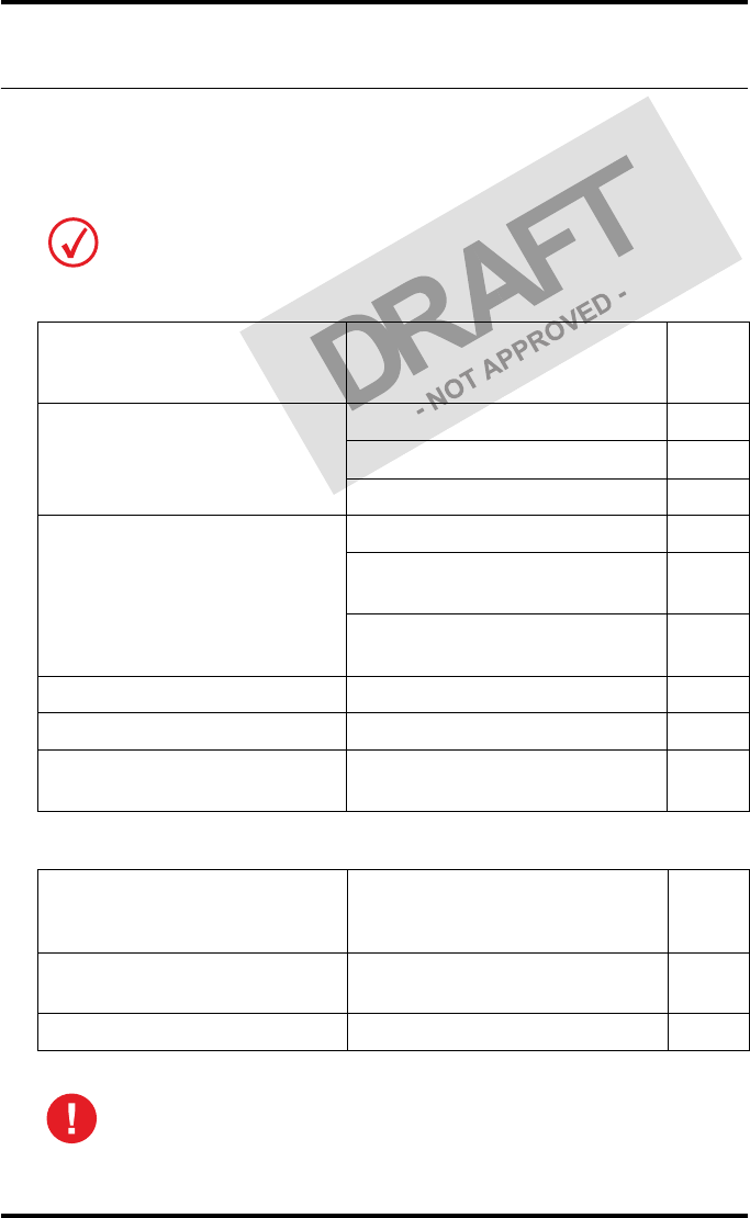
The Drystar 5302 features the following functions on the main menu level of
the key-operator mode:
These functions are described in detail in the Drystar 5302 Reference manual.
Menu item Function
Page
(Ref.
Man.)
Show settings To consult the current settings of the printer.
50
Change settings To change the current settings of the printer.
56
Print image
To print one of the Drystar 5302 test images.
To load and print images from an external
CF-card.
86
Save configuration To make a backup of the printer settings.
90
Restore
configuration To restore the backup of the printer settings.
92
Calibration To calibrate the printer.
97
Service actions To view error, repair and maintenance data.
105
Quality Control To perform the QC procedure.
(User
Manual)
47
Installation To install or update the Drystar 5302 software.
118
Refer to the indicated page of the Drystar 5302 Reference manual for an
explanation of the function and the appropriate procedures.

47
2831A EN 20041201 Advanced operation (key-operator mode)
DRYSTAR 5302 USER MANUAL
Quality Control
In order to establish and maintain consistent image quality, a regular
evaluation of image quality is advised.
The Drystar 5302 contains an automatic QC feature that has been designed to
comply with the grayscale reproduction constancy test, according to the
international standard IEC 1223-2-4.
Local Regulations may require other procedures.
The Drystar 5302 QC procedure consists of two main steps:
•Before initial use, establishing a number of reference values that will be
used for further follow-up and verifying initial image quality.
•After establishing these values, performing regular daily, weekly and
annual quality tests.
The results of these tests are recorded on Quality Control Charts.
The QC image (Refer to ‘QC test image’ on page 52) has several additional
fields where the QC data can be filled in. This image should be filed as part of
the QC procedure.
For more information, please refer to ‘Quality Control Charts’ on page 75.

48 2831A EN 20041201Advanced operation (key-operator mode)
DRYSTAR 5302 USER MANUAL
Establishing the reference values and verifying image quality
After installation of a new Drystar 5302 and before initial use you must
establish Quality Control aim values. These values will be used as the base
line for comparison when daily Quality Control is done. These values should
be determined again after major service, repair or software update.
The following Quality Control aim values must be determined:
•The daily operating density levels. Refer to ‘Establishing the daily operating
reference density levels’ on page 49.
•Drystar 5302 image geometry. Refer to ‘Establishing the image geometry
reference values’ on page 52.
Once Quality Control aim values are established you must evaluate the
Spatial Resolution, the Artifact Levels and the Low Contrast Visibility to
determine if the image quality is acceptable. Refer to ‘Verifying Acceptable
Spatial Resolution, Artifact Levels and Low Contrast Visibility’ on page 54.
The Quality Control aim values, the Spatial Resolution and Artifact Levels and
the Image Geometry values are all recorded on the Quality Control charts.
Refer to ‘Quality Control Charts’ on page 75.
On these charts, the following test conditions are also recorded:
•The type and serial number of the Drystar 5302.
•The type and emulsion number of the film used to determine the reference
values.
•The time (day, month, year) that the values were established.
Before you can establish the daily operating levels, the Drystar 5302 must
be switched on for at least 15 minutes and it must be calibrated as well.
Refer to ‘Switching on the Drystar 5302’ on page 30 and ‘Performing the
calibration procedures’ on page 97 of the Drystar 5302 Reference manual.
49
2831A EN 20041201 Advanced operation (key-operator mode)
DRYSTAR 5302 USER MANUAL
Establishing the daily operating reference density levels
This procedure enables you to establish the base line values for:
•Low density
•Mid density
•High density
To establish the daily operating levels, proceed as follows:
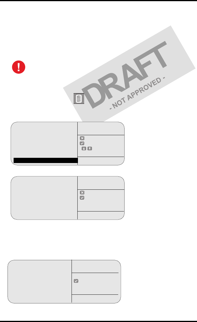
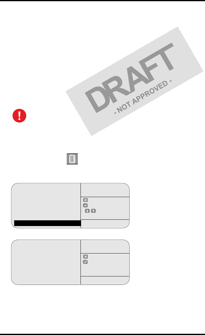
1Press the Key-operator key to enter the Key-operator mode.
2Press the down key seven times, followed by the ok key to select ‘QC’.
The ‘QC’ screen appears:
3Press the ok key to continue.
The Drystar 5302 will automatically print the QC Test image.
4After the image is printed, the system will display the optical density values:
The densitometer of the Drystar 5302 is calibrated at installation.
Authorized service personnel should recalibrate the densitometer
annually or after major service or repair.
1 Show settings
2 Change settings
3 Print image
4 Save configuration
5 Restore configuration
6 Calibration
7 Installation
8 QC
quit
ok
select
Key-operator
main menu
QC
Start printing test image
to perform:
daily / weekly
and yearly control
quit
ok
Key-operator
QC
QC
Internal Density readings
Low density :0.26
Mid density :1.35
High density :1.89
(copy on control chart)
ok
Key-operator
QC
50 2831A EN 20041201Advanced operation (key-operator mode)
DRYSTAR 5302 USER MANUAL
The displayed values represent the following steps on the test film:
•Low density: the density of the Low density step.
Target: 0.4.
•Mid density: the density value of the Mid density step.
Target: 1.2.
•High density: the density value of the High density step.
Target: 2.0.
5Record the density levels on the Drystar 5302 Chart 1 (‘Determination of the
operating levels’). Refer to ‘Quality Control Charts’ on page 75.
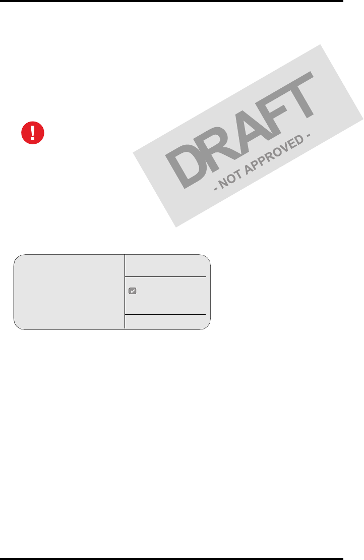
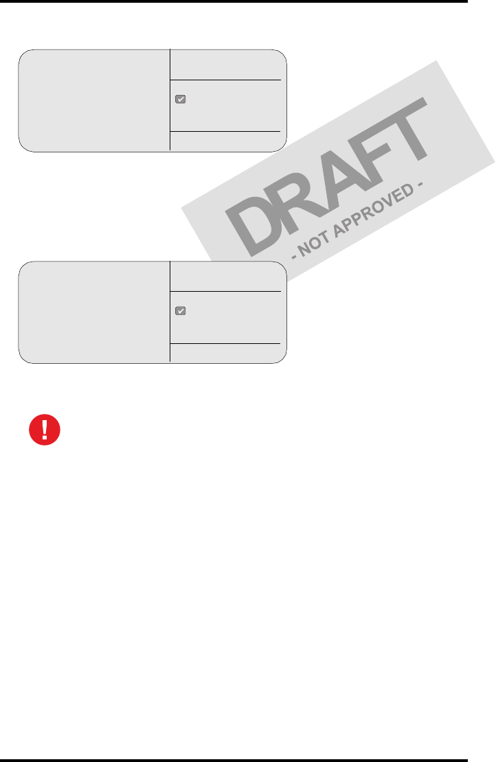
6Press the ok key. The following screen is displayed:
If the mid density value does not meet or exceeds the recommended
values, the reason must be found and the problem solved before any
further clinical films can be printed.
Refer to ‘Preventive maintenance schedule’ on page 59 and ‘Maintaining image
quality and resolving image quality problems’ on page 173 of the Drystar 5302
Reference manual, or call your local Agfa service organization.
QC
Proceed with the QC proce-
dure as stated in the User man-
ual ok
Key-operator
QC
51
2831A EN 20041201 Advanced operation (key-operator mode)
DRYSTAR 5302 USER MANUAL
7Press the ok key to return to the main menu.
8Repeat 1 steps through 7 once a day for five consecutive days, as indicated on
the Drystar 5302 Chart 1.
9Calculate the average value of the densities from the five images. These values
represent operating levels, or aim values, for each density.
10 Record the respective aim (average) values as the ‘Operating levels’ on the
Drystar 5302 Charts 2a and 2b (‘daily Drystar 5302 control chart’). Refer to
‘Quality Control Charts’ on page 75.
The calculated ‘Operating levels’ should be as following:
11 These charts will be used for the daily quality test. For more information, refer
to ‘Performing the daily QC test’ on page 55.
Operating Level Value
(according IEC 1223-2-4 or beter)
Low density 0.4 ± 0.05
Mid density 1.2 ± 0.15
High density 2.0 ± 0.2
52 2831A EN 20041201Advanced operation (key-operator mode)
DRYSTAR 5302 USER MANUAL
Establishing the image geometry reference values
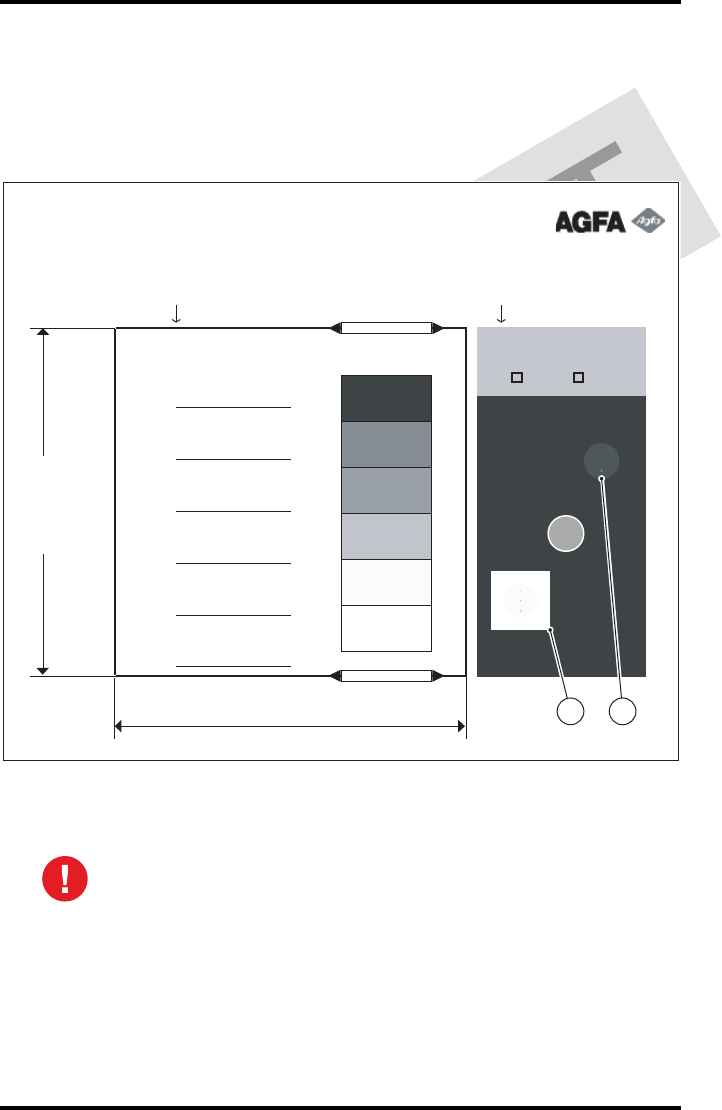
1Print the QC test image or use the previously printed test image.
You should obtain an image looking like this (without the dimensions A and B):
QC test image
2To determine the reference values for geometry, measure the dimensions
A and B of the geometric square on the test image.
Make sure to measure distance A from the left edge of the left line to the
right edge of the right line and distance B from the upper edge of the
upper line to the lower edge of the lower line.
We strongly recommend using a 30 cm (12-inch) machinist scale with
0.5 mm divisions (1/64 inch).
Drystar 5302
Quality Control Test Image
Date: __________
Time: __________
Initials: ________
Weekly Spatial
Resolution Test
Geometry Test
Daily density test
Max D
Hi D
Mid D
Lo D
Base
+ Fog
DD
Density Difference
(Hi D - Lo D)
Sets of dots visible?
Yes No
Dimension A
Dimension B
1 2

53
2831A EN 20041201 Advanced operation (key-operator mode)
DRYSTAR 5302 USER MANUAL
3Record these values as reference dimensions A ref and B ref on the Drystar 5302
Chart 4 (‘Drystar 5302 Geometric Consistency Control Chart’). Refer to ‘Quality
Control Charts’ on page 75.
These charts will be used for the annual quality test. For more information, refer to
‘Performing the Annual QC tests’ on page 58.
4Save this film for future reference.

54 2831A EN 20041201Advanced operation (key-operator mode)
DRYSTAR 5302 USER MANUAL
Verifying Acceptable Spatial Resolution, Artifact Levels and Low Contrast
Visibility
1Print the QC Test image or use the previously printed QC Test image used to
establish the daily operating density levels.
2Visually check the QC test image for artifacts: no significant disturbing artifacts
should be visible.
3Check the spatial resolution in each of the three ovals. Within each oval there
are three groups, each having five dots. All five dots of each group must be
visible with a magnifying glass. The smallest cluster of 5 dots are only visible if
the viewing conditions are good.
4Record these values at the top of the Drystar 5302 Chart 3 (Drystar 5302
Artifacts and Spatial Resolution Control Chart). Refer to ‘Quality Control Charts’
on page 75.
5Check the Low Contrast Visibility at both the high (100 / 95%) and low end
(0 / 5%) of the density scale. You should be able to see the circle in the square
(refer to item 1 on the ‘QC test image’ on page 52) and the upper circle (refer to
item 2 on the ‘QC test image’ on page 52).
6These charts will be used for the weekly quality test. For more information,
refer to ‘Performing the Weekly QC tests’ on page 57.
Good viewing conditions are important for the correct interpretation of
both diagnostic and test images. Make sure that the lightbox intensity
(luminance) is between 2000 and 4000 cd/m² (4500 and 6500 °K). Use a
magnifying glass and use shutters to collimate. Make sure the ambient
light is low.
In case of significant artifacts or insufficient spatial resolution, the reason
must be found and the problem solved before any further clinical films can
be printed.
Refer to ‘Preventive maintenance schedule’ on page 59 and ‘Maintaining image
quality and resolving image quality problems’ on page 173 of the Drystar 5302
Reference manual, or call your local Agfa service organization.
55
2831A EN 20041201 Advanced operation (key-operator mode)
DRYSTAR 5302 USER MANUAL
Performing quality control (QC) tests
The following procedures must be performed daily, weekly or annually as
indicated.
The reason for performing quality control tests is to determine if any
significant image quality variation or deterioration has occurred which may
require corrective action. Comparing the results of the tests with the reference
values previously established does this.
This procedure allows the operator to take the necessary preventive actions
before any image quality loss can take place.
Performing the daily QC test
1Turn on the Drystar 5302 and wait at least for 15 minutes. Refer to ‘Switching on
the Drystar 5302’ on page 30.
2Press the Key-operator key to enter the Key-operator mode.
3Press the down key seven times, followed by the ok key to select ‘QC’.
The ‘QC’ screen appears:
4Press the ok key to continue.
The Drystar 5302 will automatically print the QC Test image.
This test must be performed every day before any clinical film can be
processed.
1 Show settings
2 Change settings
3 Print image
4 Save configuration
5 Restore configuration
6 Calibration
7 Installation
8 QC
quit
ok
select
Key-operator
main menu
QC
Start printing test image
to perform:
daily / weekly
and yearly control
quit
ok
Key-operator
QC
56 2831A EN 20041201Advanced operation (key-operator mode)
DRYSTAR 5302 USER MANUAL
After the image is printed, the system will display the optical density values:
5Record the density values on the Drystar 5302 Charts 2A and 2B (Drystar 5302
Daily Density Control Chart’). Also record the date and time of the test on the
charts and on the QC test images. Refer to ‘Quality Control Charts’ on page 75.
6Press the ok key. The following screen is displayed:
7Press the ok key to return to the main menu.
In case the measure results are not within the aim values, the reason for
the unacceptable density variations must be identified and resolved before
any further clinical films can be processed. This may include repeating the
film calibration procedure.
For possible causes of non-compliance and the respective actions, refer to
‘Preventive maintenance schedule’ on page 59 and ‘Maintaining image quality
and resolving image quality problems’ on page 173 of the Drystar 5302
Reference manual.
QC
Internal Density readings
Low density :0.19
Mid density :1.25
High density: 1.78
(copy on control chart)
ok
Key-operator
QC
QC
Proceed with the QC proce-
dure as stated in the User man-
ual
ok
Key-operator
QC

57
2831A EN 20041201 Advanced operation (key-operator mode)
DRYSTAR 5302 USER MANUAL
Performing the Weekly QC tests
Spatial Resolution, Artifact Test and Low Contrast Visibility
To identify artifacts and verify spatial resolution you must perform the
following test weekly or as needed for troubleshooting image quality
problems.
1Check the QC test image visually for artifacts: no significant disturbing artifacts
should be visible.
2Check the spatial resolution.
The test film also shows three squares which each contains an oval. These 3 ovals
contain 3 groups, each having 5 dots. All five dots of each group must be visible with a
magnifying glass. The smallest cluster of 5 dots are only visible if the viewing
conditions are good.
3Check the Low Contrast Visibility at both the high (100 / 95%) and low end
(0 / 5%) of the density scale. You should be able to see the circle in the square
(refer to item 1 on the ‘QC test image’ on page 52) and the upper circle (refer to
item 2 on the ‘QC test image’ on page 52).
4Record these values on the Drystar 5302 Chart 3 (Drystar 5302 Artifacts and
Spatial Resolution Control Chart).
Good viewing conditions are important for the correct interpretation of
both diagnostic and test images. Make sure that the lightbox intensity
(luminance) is between 2000 and 4000 cd/m² (4500 and 6500 °K). Use a
magnifying glass and use shutters to collimate. Make sure the ambient
light is low.
In case of significant artifacts, insufficient spatial resolution or failure of
any other recommended QC tests, the cause of the problem must be
identified, and corrective action must be taken before the Drystar 5302
can be used for any further clinical imaging.
Refer to‘Preventive maintenance schedule’ on page 59 and ‘Maintaining image
quality and resolving image quality problems’ on page 173 of the Drystar 5302
Reference manual, or call your local Agfa service organization for
assistance.

58 2831A EN 20041201Advanced operation (key-operator mode)
DRYSTAR 5302 USER MANUAL
Performing the Annual QC tests
Geometric Consistency Test
To be able to notice fluctuations in image size and aspect ratio, you must
perform this procedure once a year.
1First, perform the daily test.
2Use the QC test image of the weekly test and measure the dimensions A and B of
the geometric square. Refer to ‘Establishing the image geometry reference values’
on page 52.
3Record these values as measured dimensions A and B on Chart 4 (‘Drystar 5302
Geometric Consistency Control Chart’).
4Compare the measured A and B dimensions with the reference dimension
values, A ref and B ref on the Drystar 5302 Chart 4 (‘Drystar 5302 Geometric
Consistency Control Chart’).
The differences between measured dimensions of A and B and the reference values A
ref and B ref should be less than or equal to 1.0%.
5Check for image distortion.
6Calculate the aspect ratio by dividing A by B.
The result must be 1 +/- 0.01
Make sure to measure distance A from the left edge of the left line to the
right edge of the right line and distance B from the upper edge of the
upper line to the lower edge of the lower line.
We strongly recommend using a 30 cm (12-inch) machinist scale with
0.5 mm divisions (1/64 inch).
If the image size or distortion values are outside of limits, contact Agfa
service to resolve the problem.
59
2831A EN 20041201 Advanced operation (key-operator mode)
DRYSTAR 5302 USER MANUAL
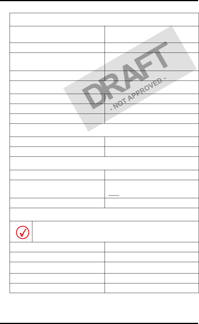
Preventive maintenance schedule
The Drystar 5302 is designed for trouble-free service. Maintenance and
cleaning involve only some minor user tasks. Refer to the following pages for
the appropriate cleaning procedure.
Safety guidelines
•Do not lubricate the printer.
•Do not attempt to disassemble the printer.
•Do not touch the resistor line of the print head.
•Always switch off the Drystar 5302 and disconnect the power cord from
the outlet before carrying out any maintenance work inside the printer.
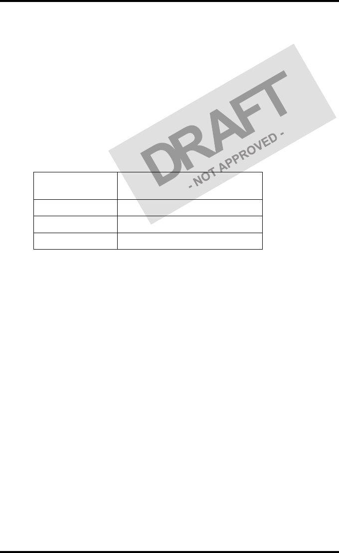
Interval What to do? Page
Ad hoc ‘Cleaning the exterior’ 60
When image quality tends to
degrade. An appropriate warning
message is displayed.
‘Cleaning the print head’ 61
To prevent damage to the printer while performing maintenance, observe
the following safety precautions:
Film jam removal or cleaning the printer head can be done without switching the
power off. Nevertheless, care should be taken and the ‘Safety precautions’ on page 9
should be respected.

60 2831A EN 20041201Advanced operation (key-operator mode)
DRYSTAR 5302 USER MANUAL
Cleaning the exterior
1Switch off the Drystar 5302 by following the procedure as described in
‘Switching off the Drystar 5302’ on page 32.
2Remove the power plug from the socket.
3Wipe the exterior of the printer with a clean, soft, damp cloth.
Use a mild soap or detergent if required but never use an ammonia–based cleaner. Be
careful not to get any liquid in the power cord port.
4Plug in the printer and switch it on by following the procedure as described in
‘Switching on the Drystar 5302’ on page 30.
61
2831A EN 20041201 Advanced operation (key-operator mode)
DRYSTAR 5302 USER MANUAL
Cleaning the print head
To clean the print head:
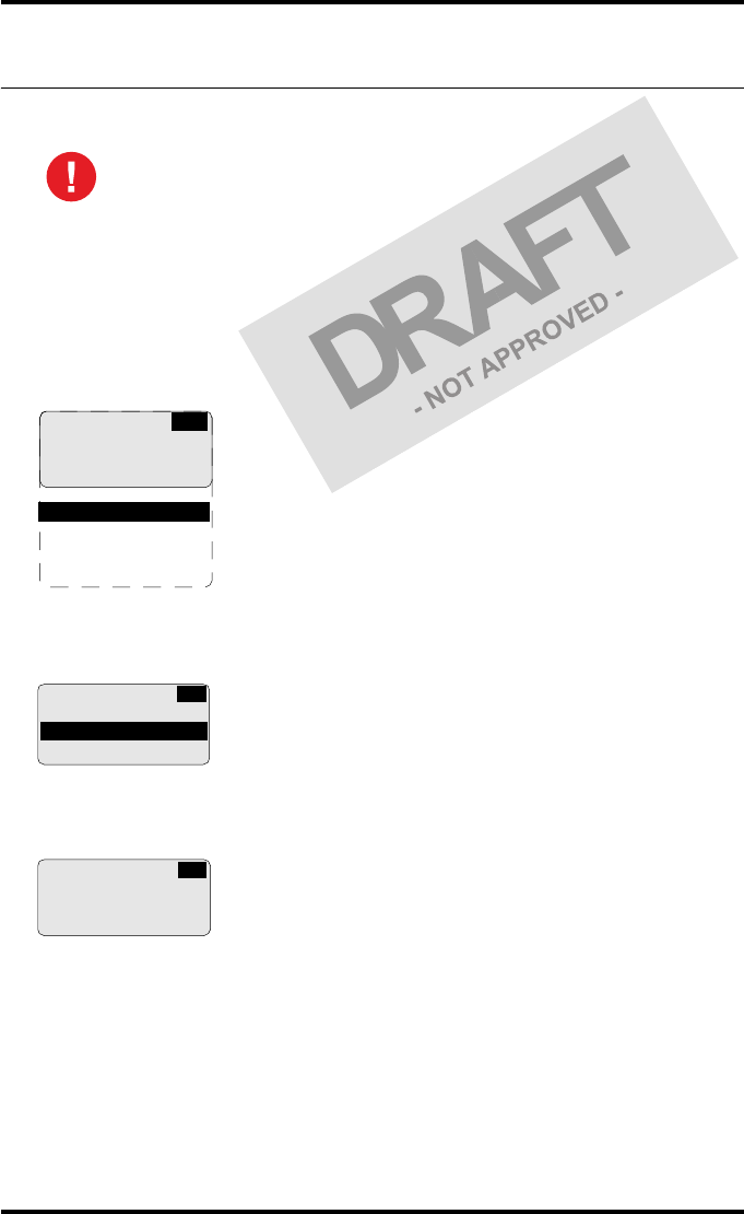
1Press the Key-operator key to enter the key-operator mode.
2On the key-operator main menu, press the Down key five times, followed by the
Confirm key to select ‘Calibration’.
3On the Calibration menu, press the Down key, followed by the Confirm key to
select ‘Therm. Head clean.’.
4The ‘Thermal head cleaning’ screen will give step by step instructions on what
to do:
Print head cleaning must be done when image quality problems occur.
1 Show settings
2 Change settings
3 Print image
4 Save configuration
5 Restore config.
6 Calibration
7 Service actions
8 Quality control
9 Installation
KO
CA
CALIBRATION
1 Film Calibration
2 Therm. Head clean.
THERMAL HEAD
CLEANING
Open top cover
CA
62 2831A EN 20041201Advanced operation (key-operator mode)
DRYSTAR 5302 USER MANUAL
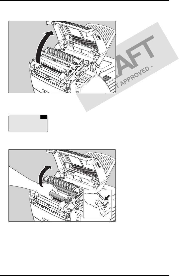
5Open the top cover.
6As soon as the top cover is opened, the ‘Thermal head cleaning’ screen
continues giving the following instructions:
7Open the hold-down bracket.
THERMAL HEAD
CLEANING
Clean thermal head
Close top cover
CA
63
2831A EN 20041201 Advanced operation (key-operator mode)
DRYSTAR 5302 USER MANUAL
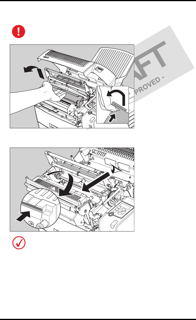
8Open the print head unit.
9Locate and check on sight the print head resistor line.
The print head unit can be warm.
Be careful not to touch the print head resistor line with your fingers.
64 2831A EN 20041201Advanced operation (key-operator mode)
DRYSTAR 5302 USER MANUAL
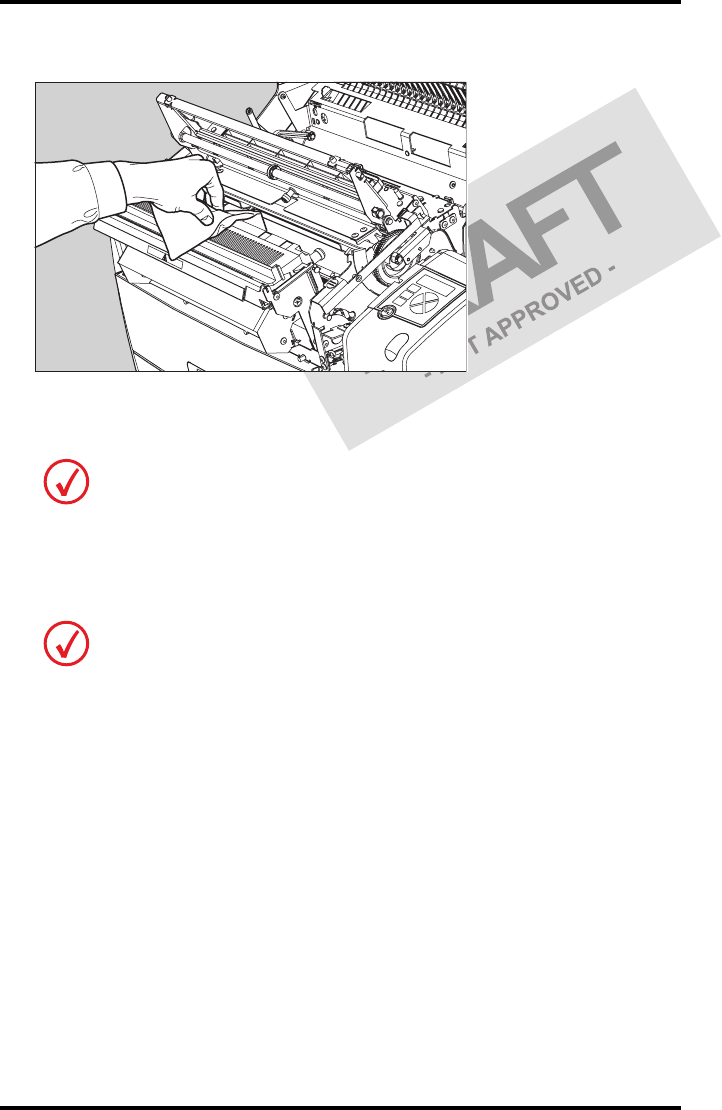
10 Clean the print head resistor line.
Gently pass over the resistor line a few times with a lint free cloth, slightly moistened
with Isopropyl alcohol or Ethanol. Do this only in one direction, i.e. from left to
right, without lifting the cloth.
11 Close the print head unit, the hold-down bracket and finally the top cover.
After you have cleaned the print head resistor line and you have closed the top cover,
the printer will restart automatically.
Do not apply any pressure on the print head because this pressure may cause
damage on the interconnections underneath the print head.
If residue dust is present as part of the cleaning procedure it will disappear after a
few prints.
65
2831A EN 20041201 Advanced operation (key-operator mode)
DRYSTAR 5302 USER MANUAL
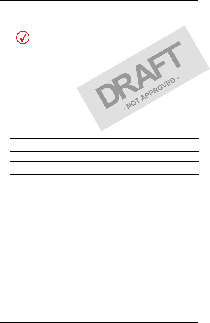
Troubleshooting checklist
The table below lists some general problems which can occur when working
with the Drystar 5302.
•The Drystar 5302 does not print.
•The quality of the printed images is bad (printing remains possible).
Refer to the appropriate pages of the Drystar 5302 Reference manual.
Action Refer to
Page
(Ref.
Man.)
Check the Drystar 5302
‘Checking the status indicator LED’ 157
‘Checking the connections’ 158
‘Checking the print queue’ 160
Remove a jammed film
‘Film input tray jams’ 162
‘Film transport jams (clearing from
the top)’ 165
‘Unauthorized opening of the
printer’ 167
Resolve error messages ‘Checking error messages’ 159
Handle CF-card errors ‘Checking CF-card error messages’ 159
Resolve film identification
problems
‘The Film Identification tag is not
readable’ 168
Action Refer to
Page
(Ref.
Man.)
Resolve film quality problems ‘Persistent white dots or lines appear
in the transport direction’ 175
Resolve warning messages ‘Maintenance messages’ 177
Have electrical or mechanical defects repaired by skilled personnel only!

66 2831A EN 20041201Advanced operation (key-operator mode)
DRYSTAR 5302 USER MANUAL

Equipment information
sheet
Appendix A

68 2831A EN 20041201Equipment information sheet
DRYSTAR 5302 USER MANUAL
Specifications
Product description
Type of product Printer
Commercial name Drystar 5302
Original seller/manufacturer Agfa-Gevaert N.V.
Labelling
TÜV-, cULus-Certification Mark,
CE-marking
CCC Mark
Dimensions
Dimensions (approx. values in cm)
•Unpacked: widthtbd, lengthtbd,
height tbd
• Packed: width tbd, length tbd,
height tbd
Weight • Unpacked: approx. 90 kg
• Packed: approx. 120 kg
RAM memory 512 Mb
Mass storage media (internal/external) Compact Flash Type II
Electrical connection
Operating voltage 100-127 V; 220-240 V AC
No external mains fuses
Mains frequency 50/60 Hz
69
2831A EN 20041201 Equipment information sheet
DRYSTAR 5302 USER MANUAL
Network connectivity
Ethernet / connectors RJ45 twisted pair for 10/100Base-TX;
Serial RS232 connection
Network protocols (TCP/IP services) FTP, Telnet, HTTP, SMTP
Image formats DICOM (Default)
TIFF
Postscript Not available
Power consumption - heat dissipation
During operation 250 W - 900 kJ/h
In standby 70 W - 252 kJ/h
Peak power (absolute max. rating) 530 W - 1908 kJ/h
Protection against
Electrical shocks Class 1 (grounded)
Ingress of water IPXØ
Environmental conditions (operation)
Room temperature Between +15°C and +30°C
Relative humidity Between 20% and 75%
Note: Films may not become wet!
Atmospheric pressure 70 kPa - 106 kPa
Environmental storage conditions
Climate conditions for storage are in accordance with EN60721-3-1-class 1K4.
Room temperature Between -25°C and 55°C (storage)
Relative humidity Between 10% and 100%
Absolute humidity Between 0.1 g/m3 and 35 g/m3
Rate of change of temperature 1°C/min
Atmospheric pressure 70 kPa - 106 kPa
70 2831A EN 20041201Equipment information sheet
DRYSTAR 5302 USER MANUAL
Environmental transport conditions
Climate conditions for transport are in accordance with
EN60721-3-2-class 2K4.
Temperature Between -40°C and 70°C (transport)
Relative humidity not combined with
rapid temperature changes 95% at +45°C
Noise emission (method of measurement in accordance with DIN 45635
part 19)
During operation Max. 64 dBA
In standby Max. 54 dBA
Consumables
Drystar DT 2B and Drystar DT 2C 8x10”, 10x12”, 11x14”, 14x14” and
14x17”film sizes
Print technology
Direct thermal printing
Reliability
Estimated product life
(if regularly serviced and maintained
according to Agfa instructions)
> 5 years and > 125,000 films
Service interventions Max. 2 interventions / 3 years
Earthquake (standard) Meets the CA requirements
71
2831A EN 20041201 Equipment information sheet
DRYSTAR 5302 USER MANUAL
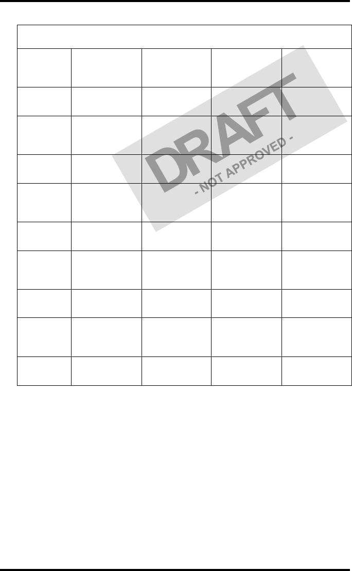
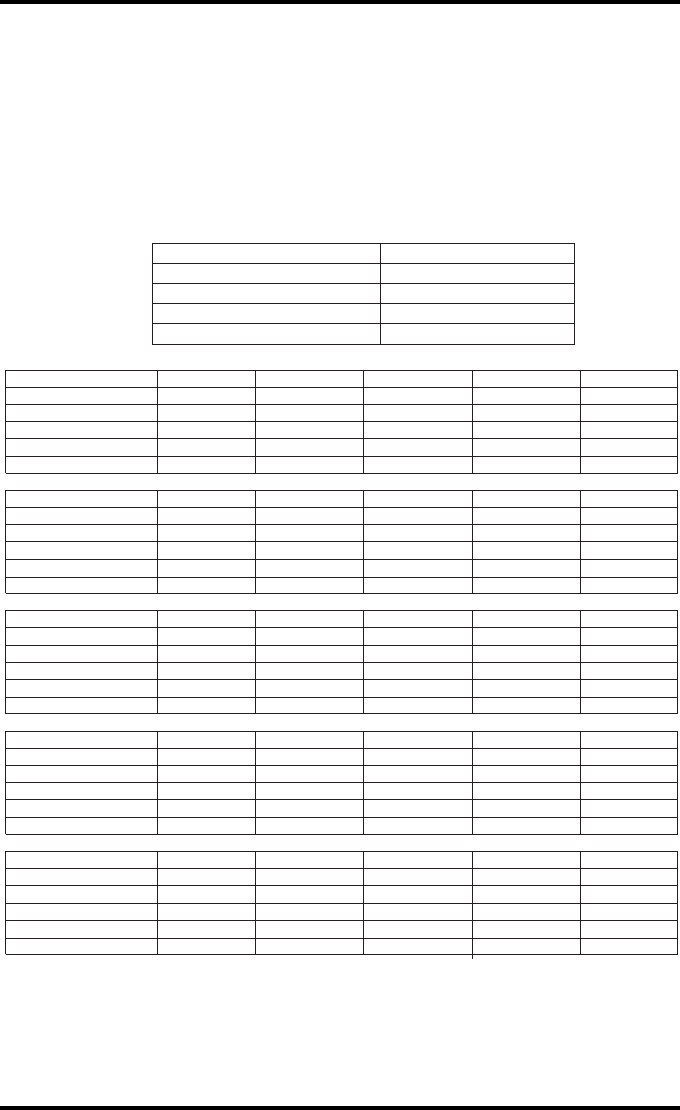
Imaging Array - Diagnostic area
Film size
8x10”
8” dimensions
in pixels
8” dimensions
in mm
10”
dimensions in
pixels
10”
dimensions in
mm
Diagnostic
area 2375.76 188.64 3072.24 243.94
Film size
10x12”
10”
dimensions in
pixels
10”
dimensions in
mm
12”
dimensions in
pixels
12”
dimensions in
mm
Diagnostic
area 3072.24 243.94 3652.84 290.04
Film size
11x14”
11”
dimensions in
pixels
11”
dimensions in
mm
14”
dimensions in
pixels
14”
dimensions in
mm
Diagnostic
area 3348.06 265.84 4358.13 346.04
Film size
14x14”
14”
dimensions in
pixels
14”
dimensions in
mm
14”
dimensions in
pixels
14”
dimensions in
mm
Diagnostic
area 4358.13 346.04 4302.72 341.64
Film size
14x17”
14”
dimensions in
pixels
14”
dimensions in
mm
17”
dimensions in
pixels
17”
dimensions in
mm
Diagnostic
area 4358.13 346.04 5232.19 415.44
72 2831A EN 20041201Equipment information sheet
DRYSTAR 5302 USER MANUAL
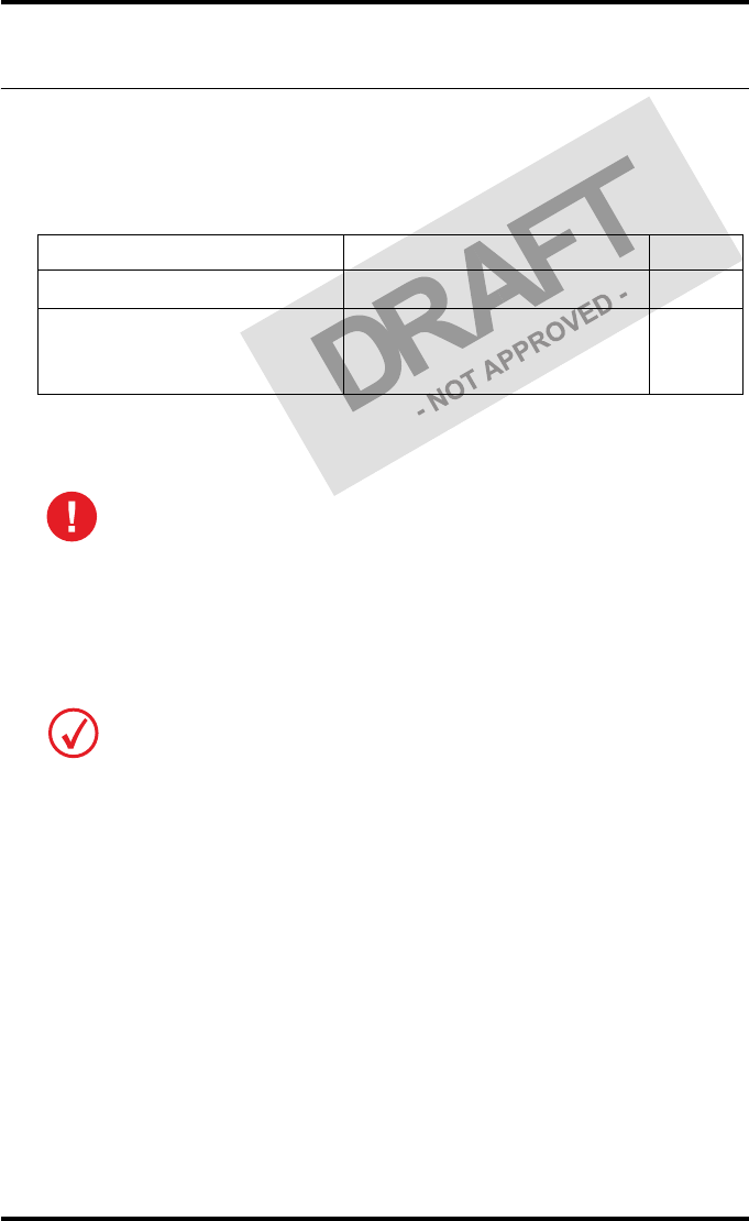
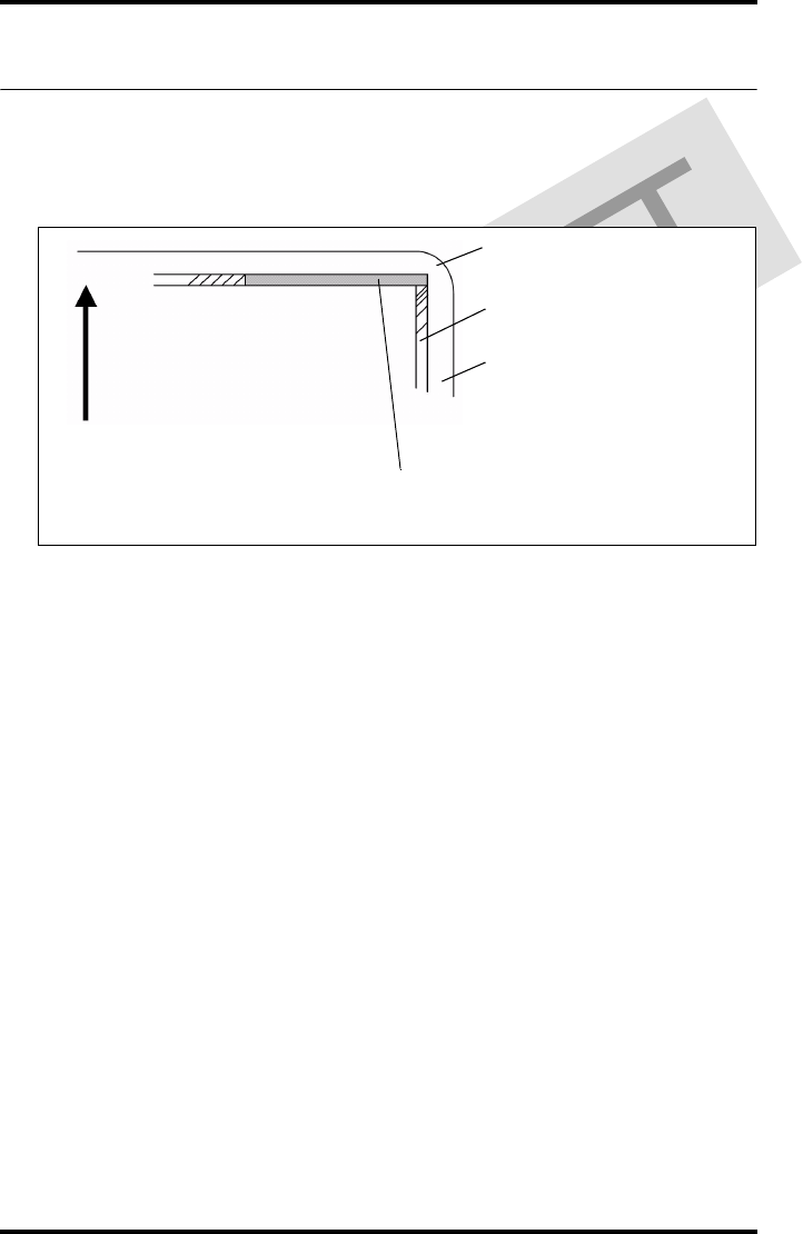
Viewing the System info area on a film
On the top right corner of each film, a “System info” area will be printed.
This info can only be read using a magnifying glass.
The System info area contains info about:
•Printer: (serial number, densitometer info, film counts, software version,
etc.),
•Controller (image source, date, time, etc.).
For more detailed information, refer to the Drystar 5302 Service
documentation.
Film
Diagnostic area
Clear border
Black border
System info area
Transport direction

73
2831A EN 20041201 Equipment information sheet
DRYSTAR 5302 USER MANUAL
Options and accessories
Mobile / Earthquake provisions
Hardware
The OPTIONAL mobile/earthquake installation kit allows you to use the
Drystar 5302 in a van, or to use it in unstable environment.
It contains the necessary equipment to fix the printer onto a table and has
provisions for easy service access.
The mobile/earthquake installation kit is delivered with the necessary
mounting instructions.
Software
No additional software for mobile/earthquake use is required.
ABC code
ABC code: tbd

74 2831A EN 20041201Equipment information sheet
DRYSTAR 5302 USER MANUAL
Connectivity
Connectivity with Agfa equipment
•Connected via VIPS or CR QS
•ADC Compact
•ADC Compact Plus
•ADC Solo
•CR 25.0
•CR 75.0
•ADR Thorax
•Impax
•MG3000
•Paxport
•MULTIFLEX
For more information, contact your Agfa representative.
Connectivity with non-Agfa equipment
Drystar 5302 is a Dicom printer and can therefore be connected to all
modalities supporting Dicom. Although, to ensure optimal operation and
image quality, Agfa has made the effort to test and release the Drystar 5302
with most of modalities on the market. For the complete list or if you want to
check on a specific modality, contact your Agfa representative.

Quality Control Charts
Appendix B
76 2831A EN 20041201Quality Control Charts
DRYSTAR 5302 USER MANUAL
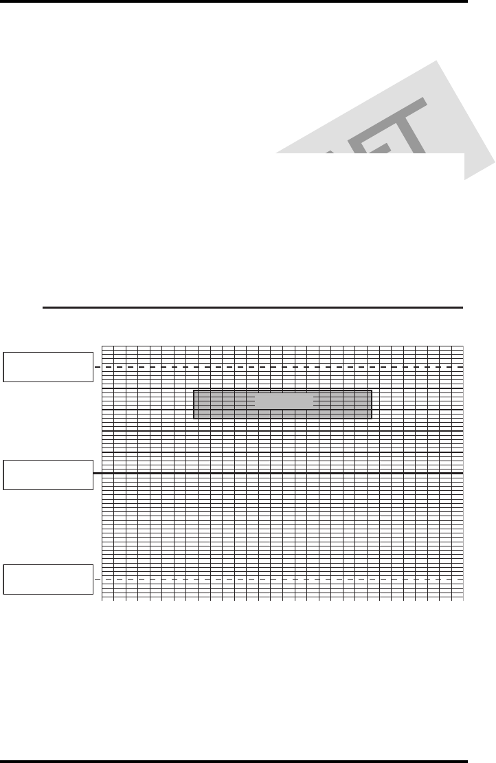
Drystar 5302: Determination of Operating Levels
Chart 1
Imager Type: __________ Serial #: _________________ Date ____________________
Film Type: ____________ Emulsion #: ______________
Densitometer Internal: _________________ (default selection)
External: Type ____________ Serial #: _________________
Day 1 Day 2 Day 3 Day 4 Day 5
Month
Day
Initials
Low Density
Average of 5 Values = operating (aim) level “Low Density”
Mid Density
Average of 5 Values = operating (aim) level "Mid Density"
High Density
Average of 5 Values = operating (aim) level “High Density”
Step 1: Print QC Test images on five consecutive days. Record the optical densities
measurements in the tables below. After five days, average the values to determine
the operating (aim) levels for each of the parameters.
Step 2: Copy the operating (aim) levels to Charts 2A/B ('Daily Density Control Chart')
77
2831A EN 20041201 Quality Control Charts
DRYSTAR 5302 USER MANUAL
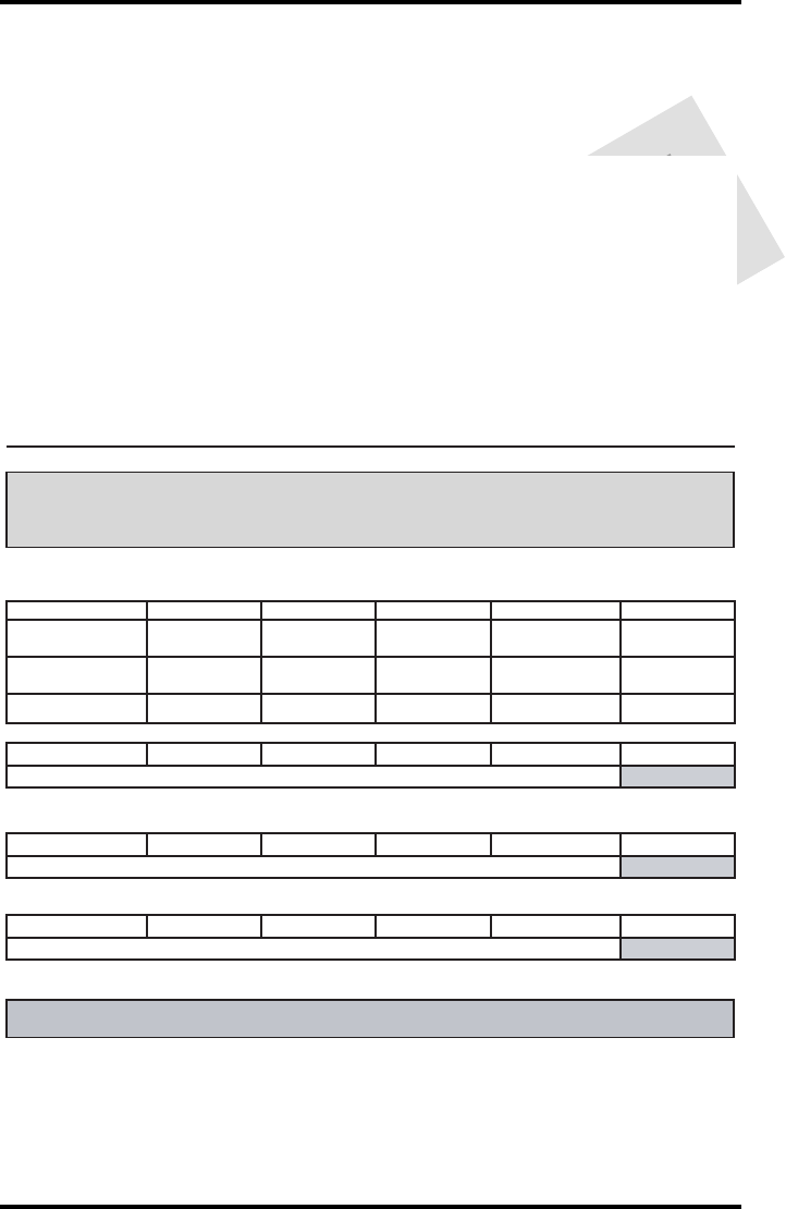
Drystar 5302 Daily Density
Control Chart
Imager Type: __________ Serial #: _____________ Film Type:____________ Emul #:___________
Densitometer Internal: ____________________ (default selection)
External: Type _______________ Serial #:________________
Date:
Initia ls:
Low Density
Mid Density
Upper Control limit =
+0.10
Low Density Aim
Lower Control Limit =
-0.10
Upper Control limit =
+0.20
Mid Density
Aim
(High - Low)
Lower Control Limit =
-0.20
Chart 2A
78 2831A EN 20041201Quality Control Charts
DRYSTAR 5302 USER MANUAL
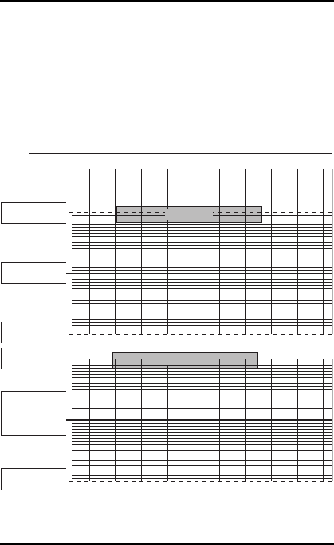
Drystar 5302 Daily Density
Control Chart
Imager
Type: __________ Serial #: _____________ Film Type:____________ Emul #:__________
_
High Density
Upper Control limit =
+0.20
Lower Control Limit =
-0.20
High Density Aim
Chart 2B
Densitometer Internal: ____________________ (default selection)
External: Type _______________ Serial #:________________
79
2831A EN 20041201 Quality Control Charts
DRYSTAR 5302 USER MANUAL
Chart 3
Drystar 5302 Artifacts and Spatial Resolution
Control Chart
Test Frequency: Weekly Drystar 5302 Serial # _____________
Initial Reference Test Date
Initial Reference Artifacts
Initial Reference Dot Visibility
Initial Reference Low Contrast
Month
Day
Artifacts
Visibility of all Dots
Month
Day
Artifacts
Visibility of all Dots
Month
Day
Artifacts
Visibility of all Dots
Month
Day
Artifacts
Visibility of all Dots
Month
Day
Artifacts
Visibility of all Dots
Low Contrast Visibility
Low Contrast Visibility
Low Contrast Visibility
Low Contrast Visibility
Low Contrast Visibility
80 2831A EN 20041201Quality Control Charts
DRYSTAR 5302 USER MANUAL
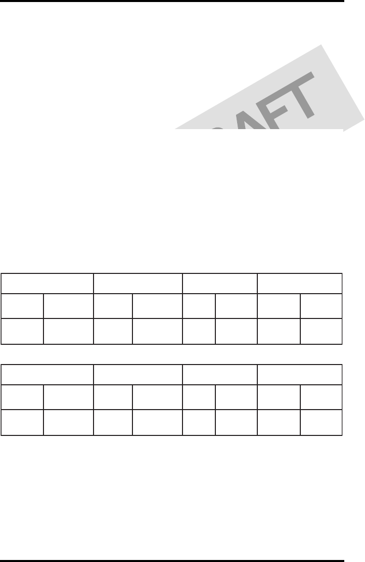
Chart 4
Drystar 5302 Geometric Consistency
Control Chart
Test Frequency: Annually or as required Drystar 5302 Serial # _____________
_
Reference Dimensions
Date:
Measured Dimensions
Date:
Consistency Aspect Ratio
Aref A: A/Aref A/B
Bref B: B/Bref
Reference Dimensions
Date:
Measured Dimensions
Date:
Consistency Aspect Ratio
Aref A: A/Aref A/B
Bref B: B/Bref

81
2831A EN 20041201 Quality Control Charts
DRYSTAR 5302 USER MANUAL

Printed in Belgium
Published by Agfa-Gevaert N.V., B-2640 Mortsel-Belgium
2831A EN 20041201