Agfa NV 5367A Drystar Axys /xxx Medical tabletop printer User Manual manual part 2
Agfa Gevaert N V Drystar Axys /xxx Medical tabletop printer manual part 2
Agfa NV >
Contents
- 1. manual part 1
- 2. manual part 2
manual part 2

51
2852 A EN 20070205
DRYSTAR AXYS
Operator mode
The Operator mode groups all basic functions that are intended for radiogra-
phers without special technical skills:
QProducing diagnostic usable hardcopies;
QLoading consumables;
QEnsuring normal operation of the printer.
The Operator mode is accessible by the keypad and by browser via a remote PC
(password protected).
All functions of the Operator mode are described in both User and Reference
manuals. Refer to the chapter “Basic operation (Operator mode)” on page 65.
Key-operator mode
The Key-operator mode groups advanced functions that are intended for techni-
cally skilled operators such as X-ray operators, network managers and service
and hospital technicians.
The Key-operator mode is accessible by the keypad and by browser via a remote
PC (password protected).
The Key-operator mode is menu-driven. The Key-operator functions are
described in the Drystar AXYS Reference manual only. Refer to the chapter
“Advanced operation (Key-operator mode)” on page 85.
Service mode
The Service mode functions are reserved for trained Service personnel. The
Service mode is accessible by browser via a remote PC (password protected).
Limited service actions (password protected) are also accessible by the keypad.

52 2852 A EN 20070205
DRYSTAR AXYS
Specialist mode
The specialist mode functions are reserved for trained service personnel of the
Agfa Customer Support Center. The specialist mode is password protected and
is only accessible by browser via a remote PC.
Administrator mode (also known as Security)
The Administrator mode functions are reserved for the System Administrator.
The Administrator mode is password protected and is only accessible by
browser via a remote PC.
53
2852 A EN 20070205
DRYSTAR AXYS
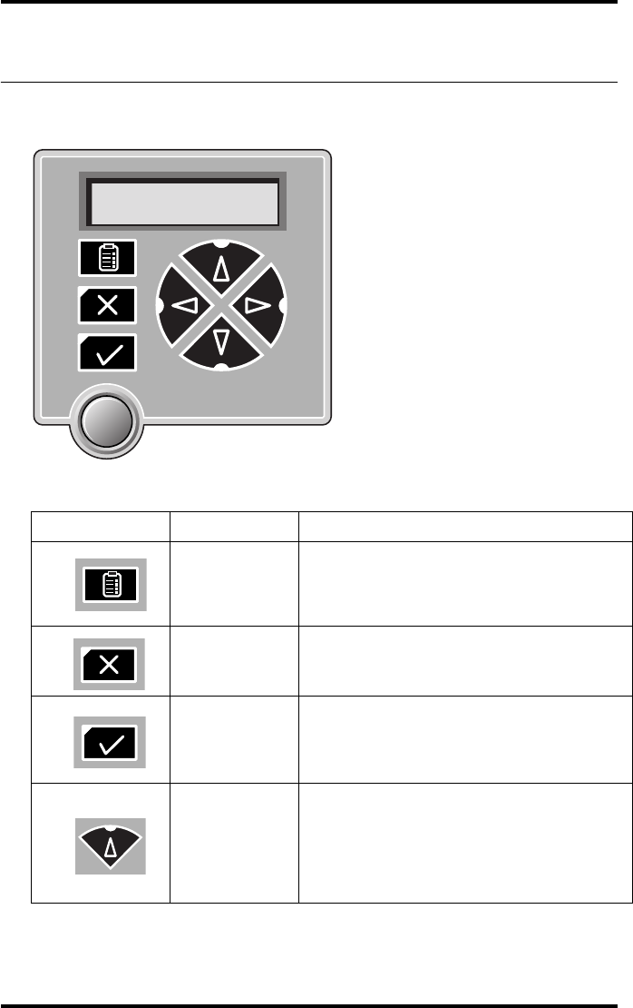
Working with the keypad
The keypad is located below the display panel.
The Drystar AXYS keypad features the following keys:
Key-operator
key
To access the advanced functions of the key-
operator mode. Refer to the chapter
“Advanced operation (Key-operator mode)”
on page 85.
Escape key To quit the current function or exit a menu
without saving modifications.
Confirm key
(In key-operator mode)
•To select a menu.
•To accept an entry in a menu
Up key
•To move the cursor to the previous entry
field.
•To scroll upwards
•To increment the number in a(n)
(alpha) numerical entry field.
Table 6: Keypad keys
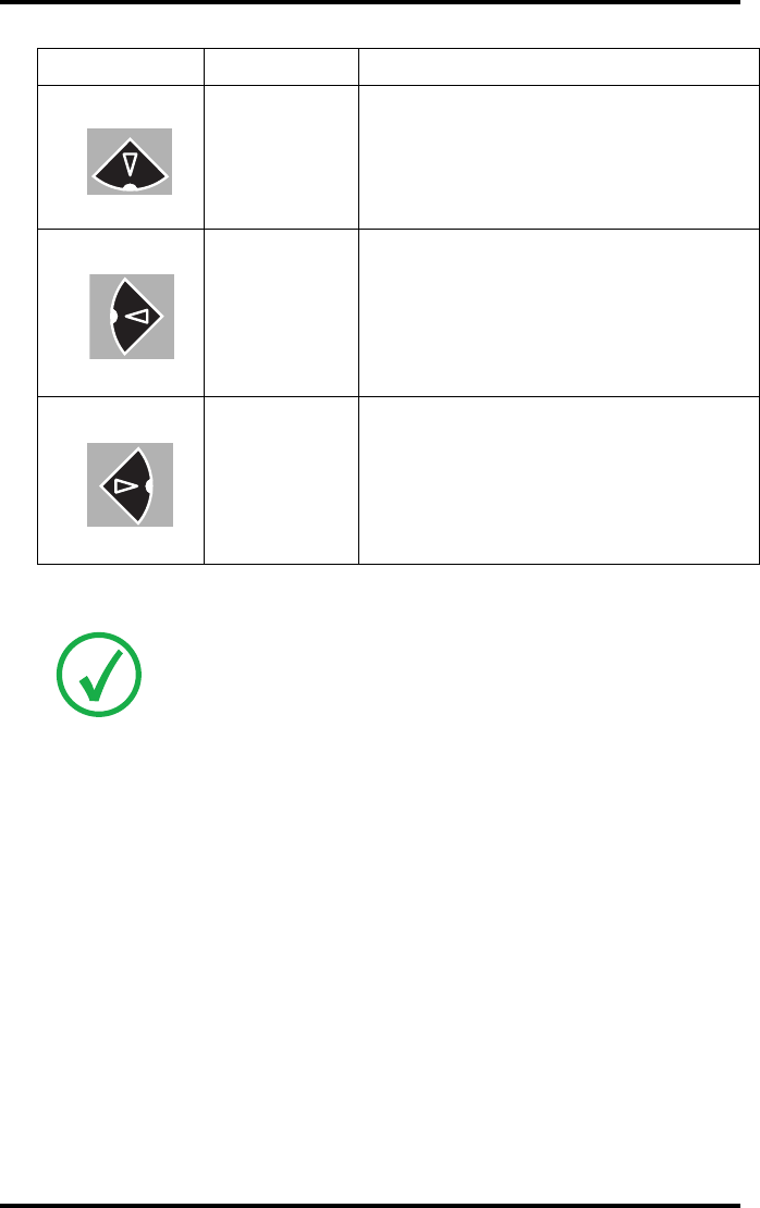
54 2852 A EN 20070205
DRYSTAR AXYS
Down key
•To move the cursor to the next entry
field.
•To scroll downwards.
•To decrement the number in a(n)
(alpha) numerical entry field.
Left key
•To scroll backwards through multiple
choices within a field.
•To move the entry position in a(n)
(alpha) numerical entry field from right
to left.
•To toggle between values in a field.
Right key
•To scroll forwards through multiple
choices within a field.
•To move the entry position in a(n)
(alpha) numerical entry field from left
to right.
•To toggle between values in a field.
Note: All keys (except the key-operator key) have an LED that is on when
the key is valid in a certain situation.
Note: You can press and hold down an arrow key to scroll quickly through a
list or a menu.
Table 6: Keypad keys
55
2852 A EN 20070205
DRYSTAR AXYS
The display
The Drystar AXYS control panel has a backlit LCD display. We distinguish two
panel types depending on the selected language:
Qa backlit LCD display with 4 lines for Western languages (e.g. Dutch, French,
Portuguese, Swedish,...).
Qa backlit LCD display with 2 lines for all other languages (e.g. Greek, Chinese,
Korean, Polish,...).
Whether a display is translated or not depends on the operating mode.
56 2852 A EN 20070205
DRYSTAR AXYS
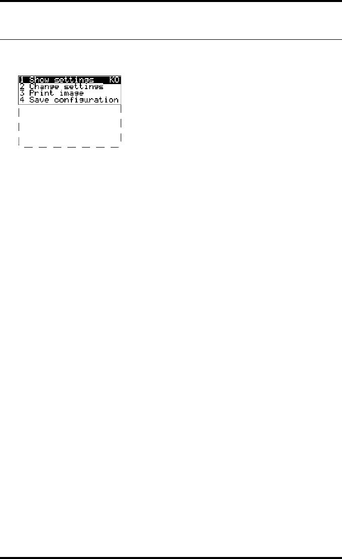
General display features
The figure below shows how the display is illustrated in this manual:
The visible display lines are indicated in the upper zone. The other possible
lines are shown in the lower zone and can be reached by scrolling using the Up/
Down arrow keys on the Keypad.
In the upper right corner, the current printer status is displayed:
QIn Operator mode, two characters display the print queue status. Refer to “Man-
aging the print queue” on page 67.
QIn Key-operator mode, two characters are displayed in reverse video to indicate
the current menu- or submenu level (e.g. ‘KO’ for Key-operator main level).
QA warning, an error or a maintenance request is displayed respectively with the
character W, E and M.
5 Restore config.
6 Calibration
7 Service Actions
8 Quality Control
9 Installation
Reachable with Up/Down arrow keys
Visible
57
2852 A EN 20070205
DRYSTAR AXYS
Operator mode
In operator mode, appropriate information is displayed in accordance with the
status of the printer.
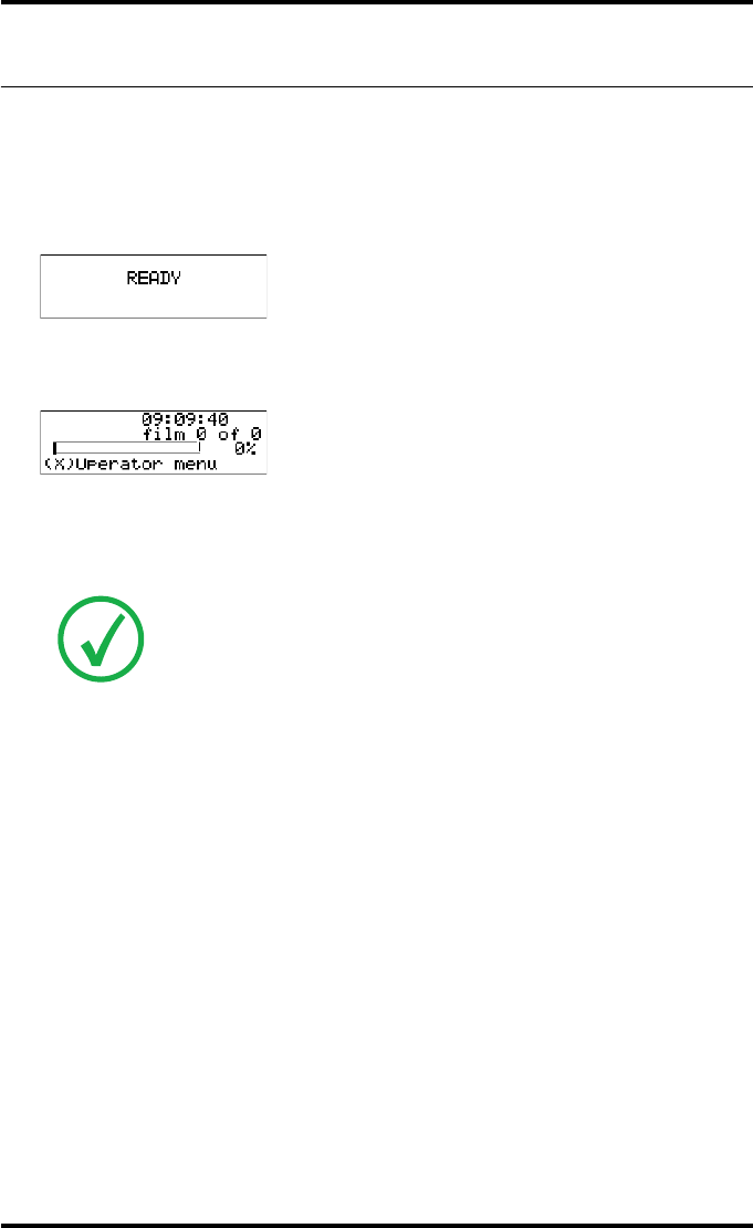
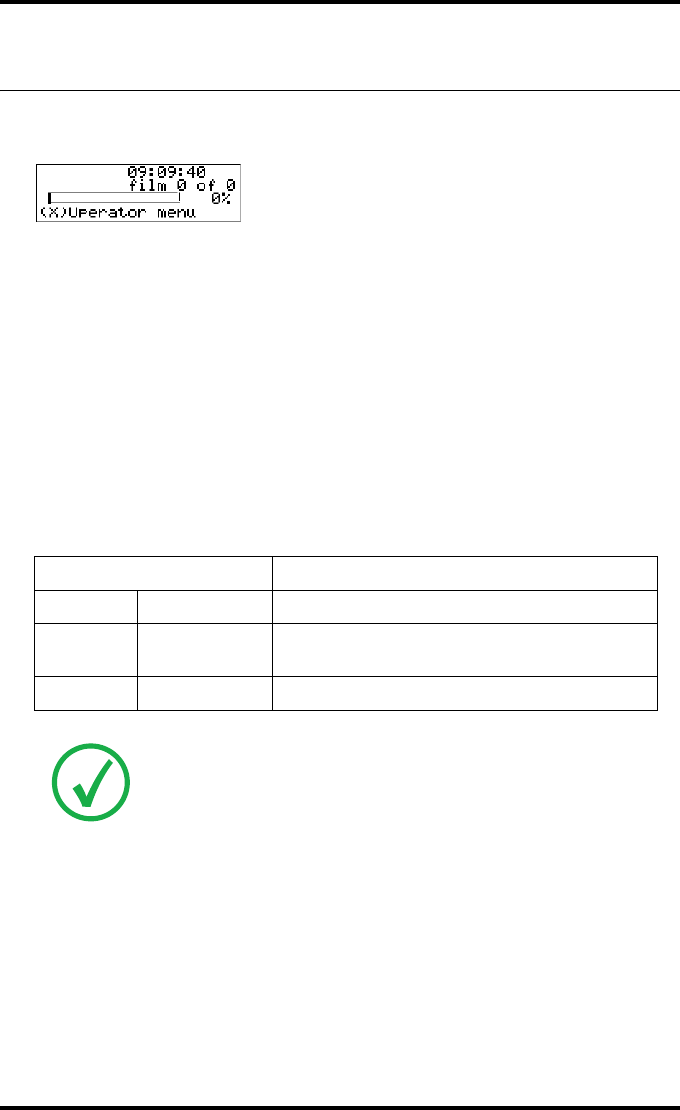
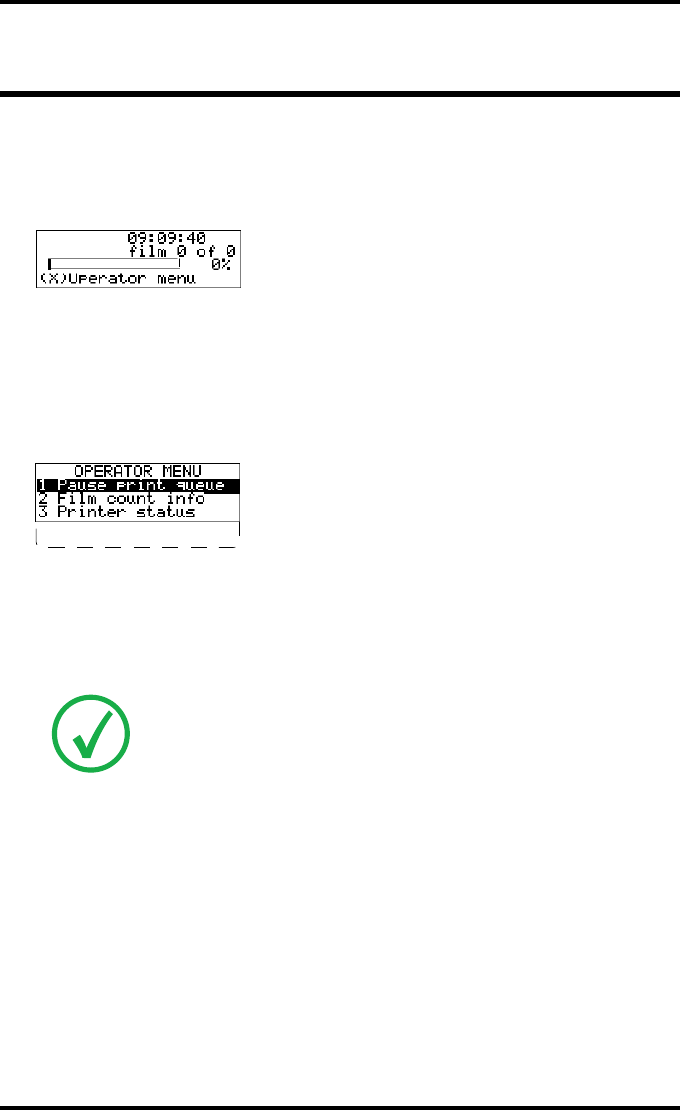
The operator basic screen looks as follows, indicating that the Drystar AXYS is
ready for operation and that no job is currently being executed.
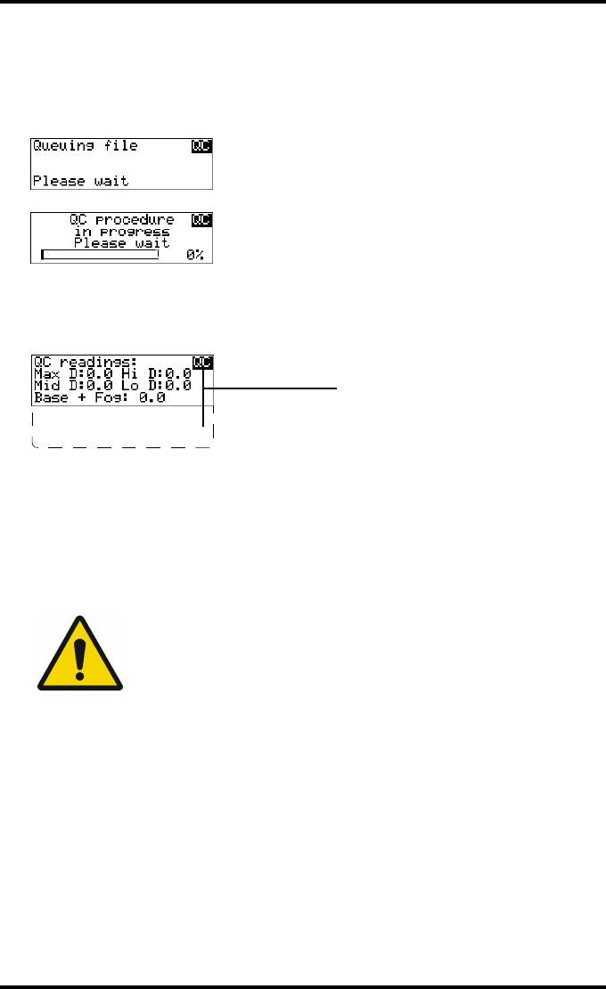
When the printer is busy with at least one print job, the print queue screen is
displayed:
The progress indicator keeps the user informed of the progress of a process
(e.g., calculation of a bitmap, printing of a film). The line is gradually filled
from left to right, from 0% to 100% as the process proceeds.
Refer to “Managing the print queue” on page 67
Note: On the print queue screen the modality name defined during
installation will be used to refer to the corresponding modality. In case a
nickname (daily used name) has been defined during installation, this
nickname will be used.
Mod.name PR
1 2
58 2852 A EN 20070205
DRYSTAR AXYS
Key-operator mode
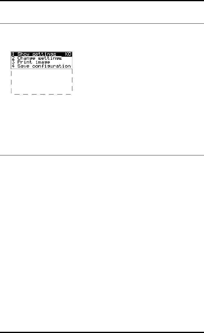
In key-operator mode, operation is menu driven. The menu displays the key-
operator functions.
The display shows only four lines. In the above figure, they are indicated in the
upper zone. The other possible lines are shown in the lower area and can be
reached by scrolling using the Up/Down arrow keys on the Keypad.
The active keys are indicated by their respective LEDs.
Data entry
When entering numerical or alphanumerical data, always adhere to the follow-
ing principles:
QOnly (alpha) numerical data can be entered.
QDuring data entry, the field is displayed in reverse mode.
QIncrement the number in a(n) (alpha) numerical entry field by pressing the Up
key. Transition from 9 to 0 of one figure will also increment the next figure to
the left, respecting the valid limits of the range.
QDecrement the number in a(n) (alpha) numerical entry field by pressing the
Down key. Transition from 0 to 9 of one figure will also decrement the next fig-
ure to the left, respecting the valid limits of the range.
QMove the entry position in a(n) (alpha) numerical entry field from right to left
by pressing the Left key.
QMove the entry position in a(n) (alpha) numerical entry field from left to right
by pressing the Right key.
QPress and hold down a key to repeat arrow key actions.
QTo accept an entry in a menu, press the Confirm key.
5 Restore config.
6 Calibration
7 Service Actions
8 Quality Control
9 Installation
Reachable with Up/Down arrow keys
Visible
59
2852 A EN 20070205
DRYSTAR AXYS
QA short beep acknowledges and terminates the entry.
QThe Drystar AXYS will sound a long beep if you press a key that is not to be used
at that moment.
Audio signals
The Drystar AXYS gives status information via beeps. The length of the beep
indicates the response of the system to a key command.
QA short beep means that Drystar AXYS has accepted the key command and is
starting the operation.
QA long beep means that you have pressed a non-active key or that the
Drystar AXYS has rejected the key command.
Note: Certain conditions can cause an interval beep. An interval beep
accompanies an error or warning message. Refer to “Troubleshooting
checklist” on page 127.
60 2852 A EN 20070205
DRYSTAR AXYS
Working with Compact flash cards
(CF-card)
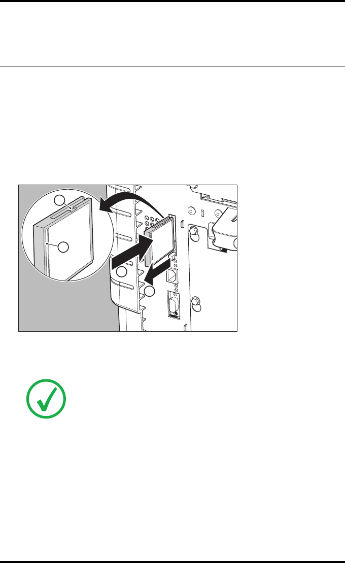
The Drystar AXYS is equipped with an external CF-card slot, which is located at
the rear side.
To insert a CF-card in the Drystar AXYS:
1Hold the CF-card vertically with the connector holes in front of the slot and with
the flat surface pointing to the left. In that case the cut-away (a) and the rim (b)
are pointing to the right.
2Insert the CF-card gently into the slot and push it until the unlocking lever
underneath the slot comes out.
Note: If you cannot push the CF-card completely into its position, this
means that you have to turn it 180 degrees (while keeping the connector
holes faced to the slot).
1
2
A
B
61
2852 A EN 20070205
DRYSTAR AXYS
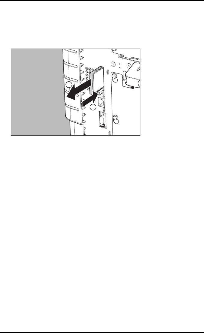
To remove a CF-card from the Drystar AXYS slot:
1Push the unlocking lever underneath the CF-card slot.
The CF-card is pushed slightly outward.
2Remove the CF-card gently from the slot.
1
2
62 2852 A EN 20070205
DRYSTAR AXYS
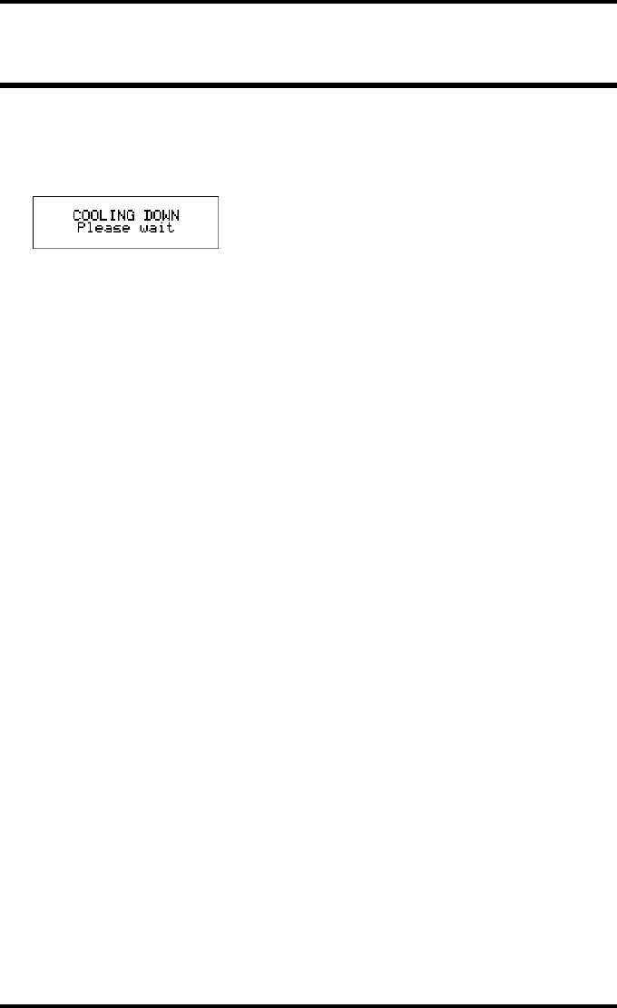
Cooling down the Drystar AXYS
If owing to certain circumstances (e.g. extensive printing), the temperature
rises too much, the Drystar AXYS will cool down automatically. The cooling
down message will appaear on the display during the cooling down process.
63
2852 A EN 20070205
DRYSTAR AXYS
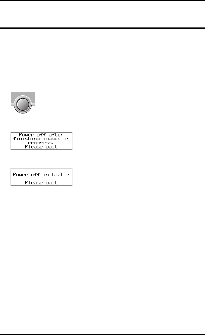
Switching off the Drystar AXYS
When you want to switch off the printer, the printer will first finish his current
print job. Queued print jobs will be stored on the hard disk and will be resumed
next time the printer is switched on.
Procedure:
1Press the Power/Reset button to switch off the Drystar AXYS.
If the printer is printing, it will finish that print job:
When the printer is ready, it shuts down immediately:

64 2852 A EN 20070205
DRYSTAR AXYS

3 Basic operation
(Operator mode)
This chapter will inform on how to manage the print queue, how to print films
with priority and how to load new films.
❑Overview of operator functions
❑Managing the print queue
❑Pausing the print queue
❑Viewing the film count info
❑Viewing the printer status
❑Deleting print jobs
❑About Drystar AXYS consumables
❑Loading films
66 2852 A EN 20070205
DRYSTAR AXYS
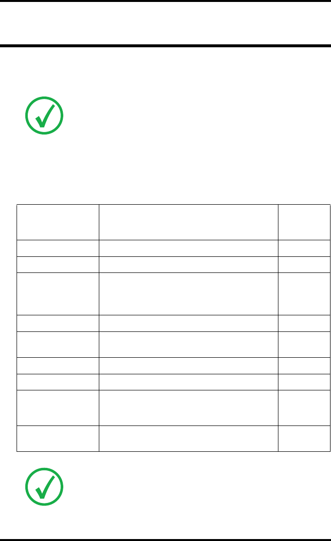
Overview of operator functions
This section focuses on the basic operating principles of the Drystar AXYS. After
reading this chapter, the operator should be able to produce diagnostic usable
hardcopies. No special technical skills are required.
All basic operator functions can be activated directly by pressing a single key on
the keypad.
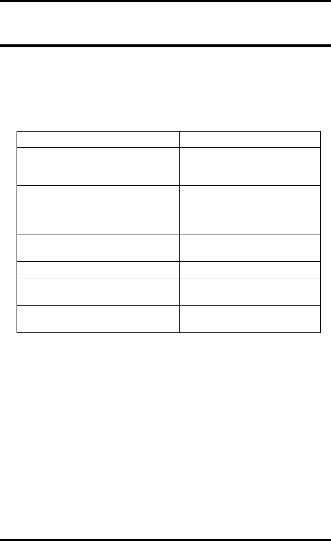
Function / Task Description
“Managing the print queue” on page 67
Jobs that have been received are
put in a print queue, waiting to be
printed.
“Pausing the print queue” on page 69
To pause the print queue. The
printer will finish the current print
job, but will not start the next print
job.
“Viewing the film count info” on page 70 To view the number of films left in
the trays.
“Viewing the printer status” on page 71 To view the current events.
“Deleting print jobs” on page 72 To remove a print job from the
print queue.
“Loading films” on page 76 Instructions for loading new films
on the printer.

67
2852 A EN 20070205
DRYSTAR AXYS
Managing the print queue
Checking the print queue
You can always check the status of the print jobs on a connected remote access
PC via the operator menu.
If jobs have been transmitted from the network to the Drystar AXYS, they are
put in the print queue on a first in, first out schedule. New jobs that are added to
the queue get the ‘waiting’ status.
As soon as the last film of a job is ejected in the output tray, the next job that has
been calculated will be put in printing status.
Note: Keep in mind that one print job can hold several films to be printed. In
accordance with the acquisition modality used and with the actual settings,
films can be grouped in a folder to be submitted as one print job for the
Drystar AXYS. Refer to the User manual of the acquisition modality for more
information.
68 2852 A EN 20070205
DRYSTAR AXYS
The local print queue screen
When the Drystar AXYS is printing, the local display shows the ‘print’ screen:
QThe screen shows information on the job that is currently being printed: the
modality name, the time of receipt of the job and the job status (refer to the
table below).
QThe progress indicator keeps the user informed of the progress of a process
(e.g., calculation of a bitmap, printing of a film). The line is gradually filled
from left to right, from 0% to 100% as the process proceeds.
QThe last line gives access to the operator menu to pause the print queue, to view
the film count info or to view the printer status. Refer to “Pausing the print
queue” on page 69 to “Viewing the film count info” on page 70 or to “Viewing
the printer status” on page 71.
A description of the possible status of the jobs is listed in the table below:
Status Description
PR Printing Printing of this job is in progress.
CA Calculating The necessary calculations are already being
made before printing of the job can be started.
WA Waiting Jobs are queued in the printer memory.
Note: On the print screen the modality name defined during installation will be
used to refer to the corresponding modality. If there is also a nickname (daily used
name) defined during installation, the nickname is used.
Mod.name PR
1 2
69
2852 A EN 20070205
DRYSTAR AXYS
Pausing the print queue
When the Drystar AXYS is printing, you can always pause the print queue by
entering the operator menu.
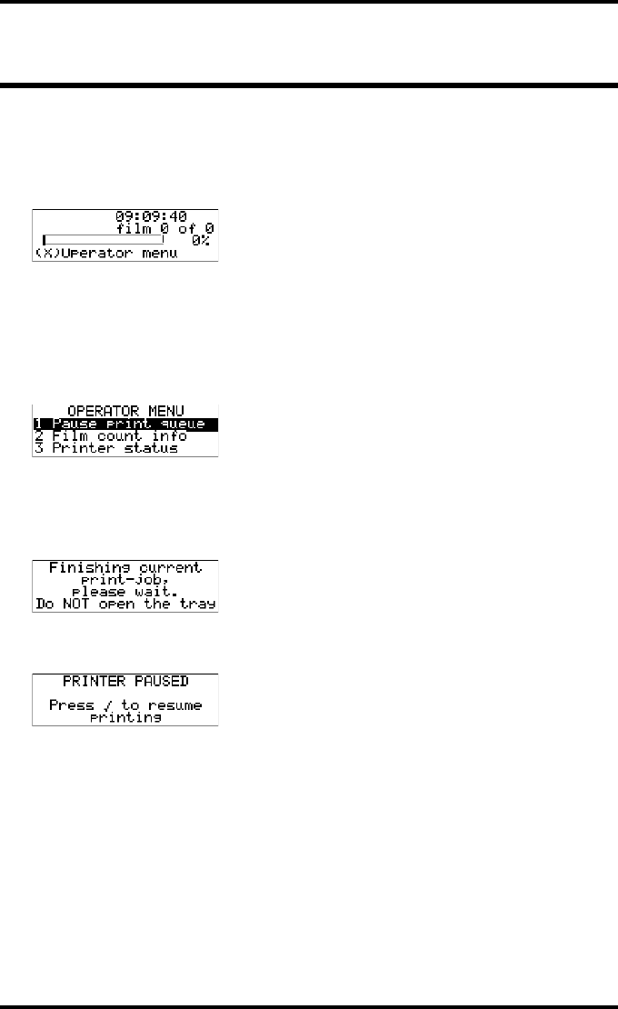
During a print job, the ‘print’ screen is displayed:
To pause the print queue, proceed as follows:
1Press the Escape key to enter the operator menu.
The ‘Operator menu’ screen appears:
2On the Operator menu press the Confirm key to select ‘Pause print queue’.
3If the printer is printing, it will first finish its current print job.
4When the printer is ready, the print queue is paused.
5To resume printing, press the Confirm key.
Mod.name PR
1 2
70 2852 A EN 20070205
DRYSTAR AXYS
Viewing the film count info
When the Drystar AXYS is printing, you can always view the number of films
left in the trays by entering the operator menu.
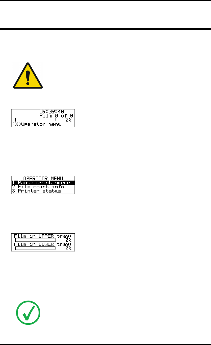
During a print job, the ‘print’ screen is displayed:
To view the number of loaded films in the trays, proceed as follows:
1Press the Escape key to enter the operator menu.
The ‘Operator menu’ screen appears:
2Press the Down key once, followed by the Confirm key to select ‘Film count
info’.
The following screen appears:
The progress bar indicates the evolutions of the film usage in an input tray. The bar is
divided into 10 parts, each part represents approximately 10% of the total films of a
film pack. The last part of the bar will disappear when more than 80% of a film pack
has been printed.
3Press the Confirm key to return to the print screen.
WARNING: Do not open the input trays to view the number of loaded
films while the Drystar AXYS is printing, but follow the procedure below:
Note: When a film job cannot be done because the tray to which the job is assigned
is empty, then the printer will check if the films in the other tray can be used for
this and other print jobs in the print queue. The printer will skip the print jobs that
cannot be done and will resume them later.
Mod.name PR
1 2
71
2852 A EN 20070205
DRYSTAR AXYS
Viewing the printer status
When the Drystar AXYS is printing, you can always view the printer status by
entering the operator menu.
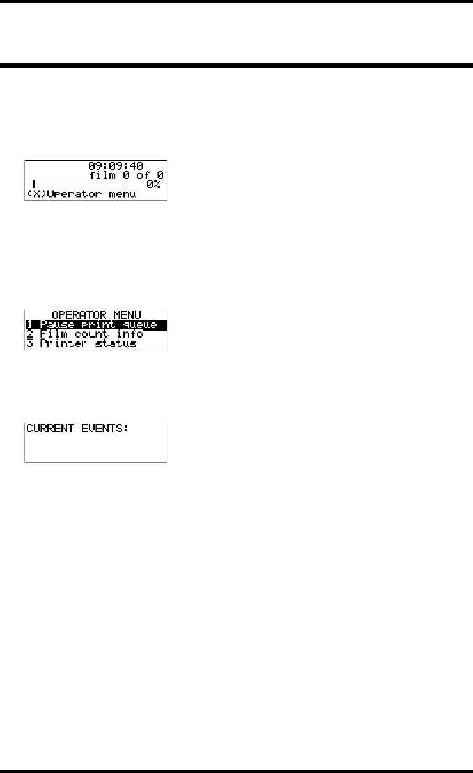
During a print job, the ‘print’ screen is displayed:
To view the printer status, proceed as follows:
1Press the Escape key to enter the operator menu.
The ‘Operator menu’ screen appears:
2Press the Down key twice, followed by the Confirm key to select ‘Printer status’.
The following screen appears:
The screen informs you, by means of short event descriptions, about current events.
There is only one event per line. An event could be e.g. a current film jams, an empty
tray,...
3Press the Confirm key to return to the print screen.
Mod.name PR
1 2
72 2852 A EN 20070205
DRYSTAR AXYS
Deleting print jobs
When the Drystar AXYS is printing, you can always delete print jobs by entering
the operator menu.
During a print job, the ‘print’ screen is displayed:
To delete a print job, proceed as follows:
1Press the Escape key to enter the operator menu.
The ‘Operator menu’ screen appears:
2Press the Down key three times, followed by the Confirm key to select ‘Delete
jobs’.
A screen appears where you can choose between the option ‘All jobs’ or one of the jobs
in the print queue:
3Do one of the following:
•If you want to delete all jobs at once, press the up/down arrow keys to select ‘All jobs’,
followed by the Confirm key. Proceed with the next step.
•If you only want to delete a specific job in the print queue, press the up/down arrow
keys to select the desired print job, followed by the Confirm key. Proceed with the next
step.
4A screen appears in which you need to confirm your delete request.
Press the Confirm key (YES) to confirm your choice, or the Escape key (NO) to quit
the procedure without any changes.
Note: Only the print queue jobs with a status different from printing (PR) or
calculating (CA) will be shown.
Mod.name PR
1 2
4 Delete jobs

73
2852 A EN 20070205
DRYSTAR AXYS
About Drystar AXYS consumables
The Drystar AXYS can handle blue-transparent DT 2 B, clear-transparent DT 2 C
(both for general radiography) and optionally the blue-transparent DT 2
Mammo (for the mammography application) films.
Available film formats for general radiography applications are 8x10”, 10x12”,
11x14”, 14x14”, and 14x17”. Available film formats for the mammography
application are 8x10”, 10x12” and 11x14”.
Both input trays can use all film formats.
When a new film pack is loaded, the Film Identification tag is read and the
printer settings are automatically adjusted.
74 2852 A EN 20070205
DRYSTAR AXYS
Labeling the input trays
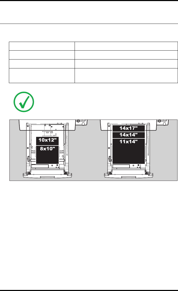
The following film types can be used:
Film type Film size
Drystar DT 2 B 8x10”, 10x12”, 11x14”, 14x14”, and 14x17”
Drystar DT 2 C 8x10”, 10x12”, 11x14”, 14x14”, and 14x17”
Drystar DT 2 Mammo
(optional) 8x10”, 10x12” and 11x14”
Note: If you want to change the film format, the tray configuration must be
modified. Refer to “Changing the film format of the trays” on page 32 for more
information.
75
2852 A EN 20070205
DRYSTAR AXYS
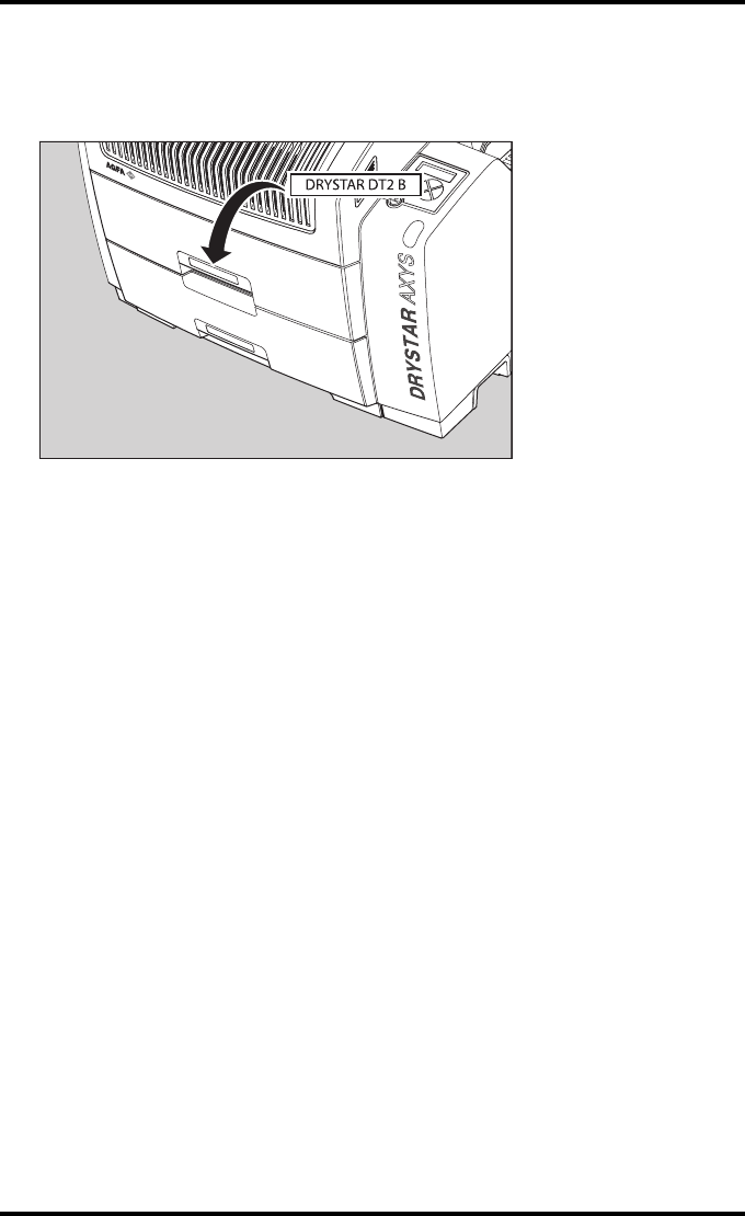
Appropriate labels have been applied on the input tray(s) by the service person-
nel at installation of the printer, indicating the type of new film to be loaded
when the tray is empty.
76 2852 A EN 20070205
DRYSTAR AXYS
Loading films
This section describes how to load the Drystar AXYS with appropriate
Drystar DT 2B and Drystar DT 2C films.
The Drystar AXYS can be loaded with 8x10”, 10x12”, 11x14”, 14x14” and
14x17” films.
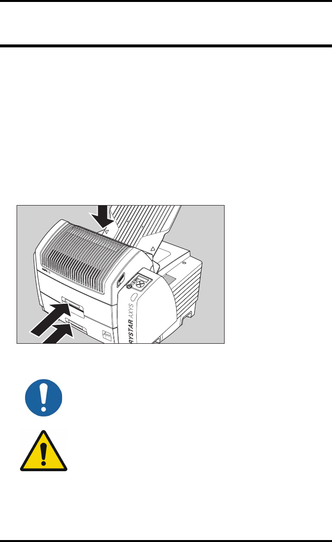
The Drystar AXYS will inform you in several ways when a film tray is empty:
Qan audible signal,
Qthe status indicator LED is blinking (red color),
Qthe display screen shows a message informing you that the input tray is empty.
The film loading procedure is identical for both input trays. In the examples
below, we will assume that the lower input tray is to be loaded.
Note: The Drystar AXYS can be loaded with new films in full daylight. Loading
films is easy and can be done very quickly. Follow the procedures as described in
this section.
Note: If you want to change the film format, the tray configuration must be
modified. Refer to “Changing the film format of the trays” on page 32 for more
information.
Note: The procedure is slightly different, depending on the fact whether the
Drystar AXYS is printing/calculating or in the ready state.
Note: When the printer is in the ready state, go to “When the Drystar AXYS is in the
ready state and an input tray is empty” on page 78.
WARNING: Make sure not to load more than one film pack in an input
tray. Loading more than one film pack in the input tray may damage the
Drystar AXYS.
77
2852 A EN 20070205
DRYSTAR AXYS
When the Drystar AXYS is printing or
calculating and an input tray is
empty
Procedure
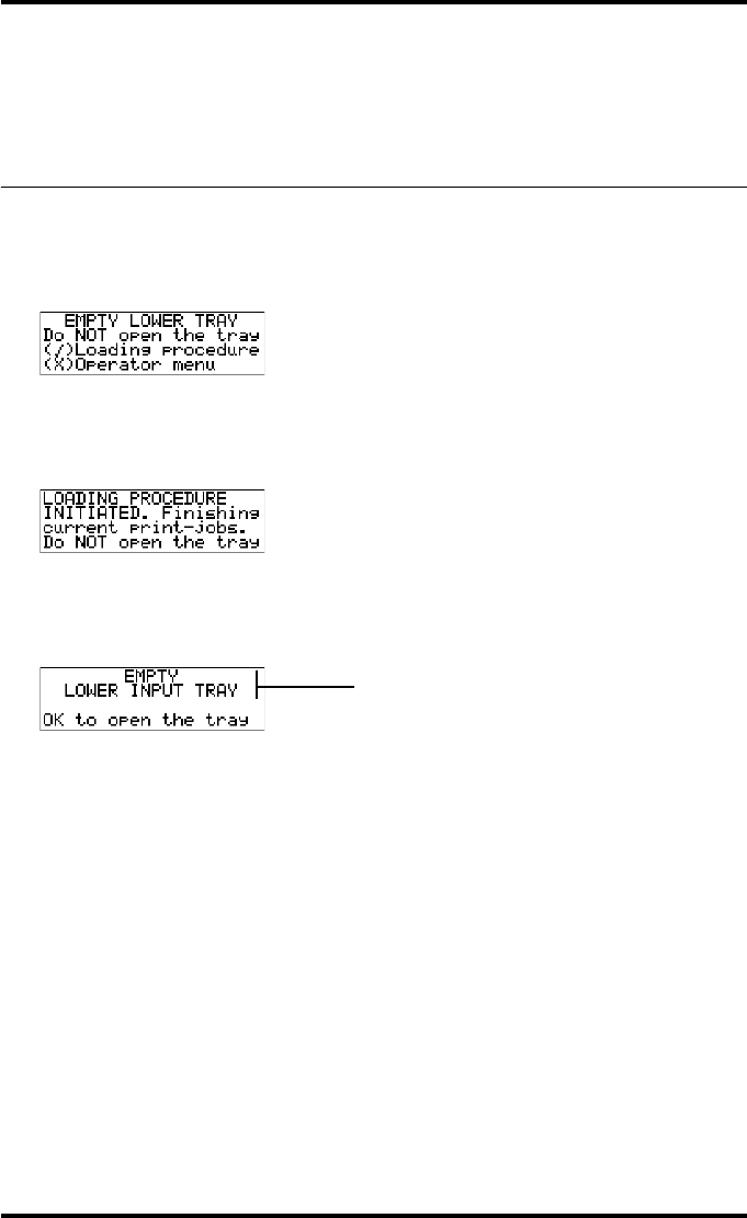
1The display shows the following message:
2Press the Confirm key to start the loading procedure.
The following screen appears when the printer is still printing:
3Wait while the printer finishes printing any current jobs.
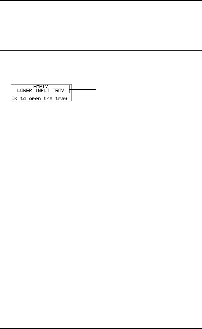
When the film path is cleared, the following screen appears automatically:
4Open the lower input tray.
5Load a new film pack.
Refer to “Film loading procedure” on page 79.
Blinking
79
2852 A EN 20070205
DRYSTAR AXYS
Film loading procedure
Procedure
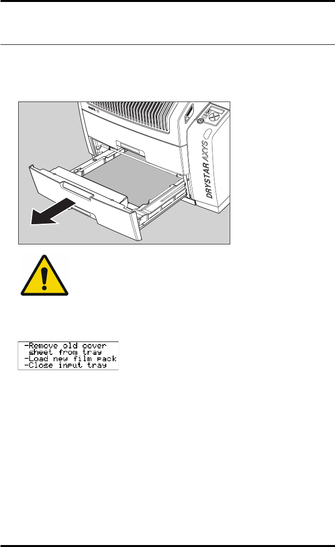
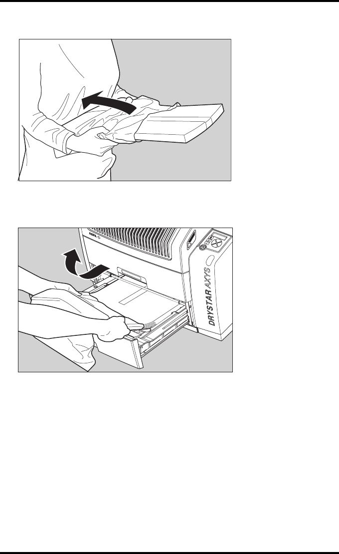
1Open the empty input tray.
2The printer is ready to start the loading procedure when the following message
appears:
3Remove the white (protective) film sheet.
WARNING: To avoid possible film jams, make sure to open input tray all
the way.
80 2852 A EN 20070205
DRYSTAR AXYS
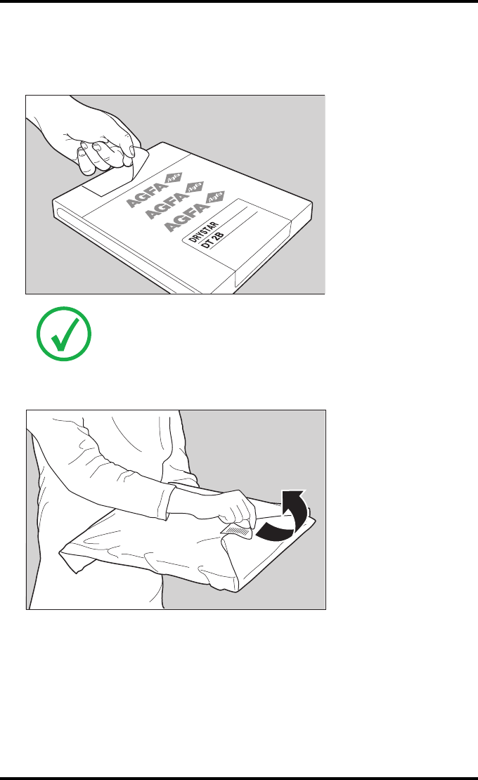
4Take film pack, and open it.
Verify that the film type on the film pack corresponds with the sticker on the tray! If
you do use an other film type, you are advised to change the label on the tray.
5Remove the sticker from the film pack.
Note: You can put the film pack onto a table to make manipulation easier. Before
you do this, make sure that the table is dust-free!
81
2852 A EN 20070205
DRYSTAR AXYS
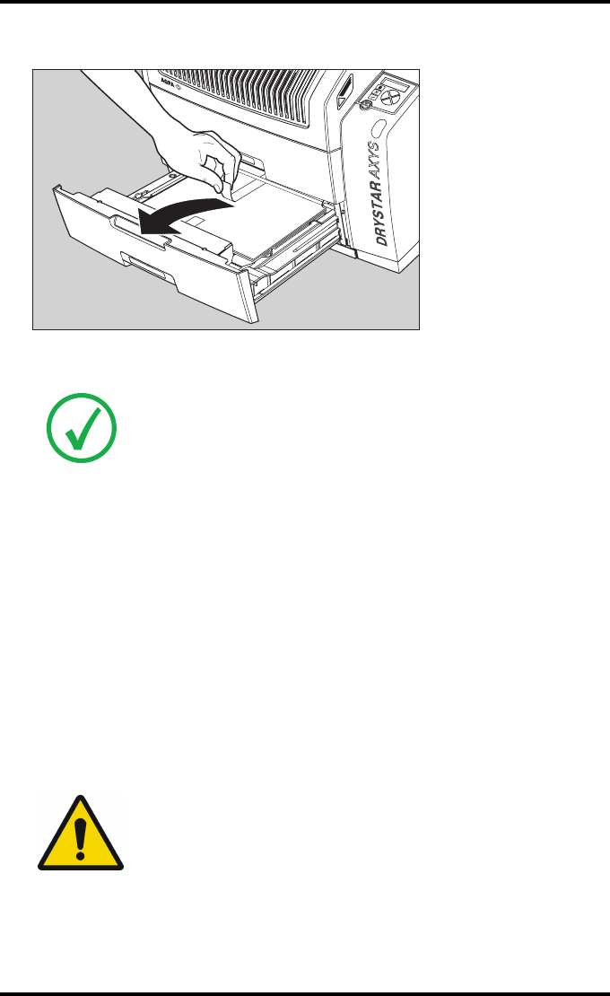
6Remove the plastic film bag partially.
7Slide the film pack into the input tray, and remove the plastic film bag com-
pletely.
82 2852 A EN 20070205
DRYSTAR AXYS
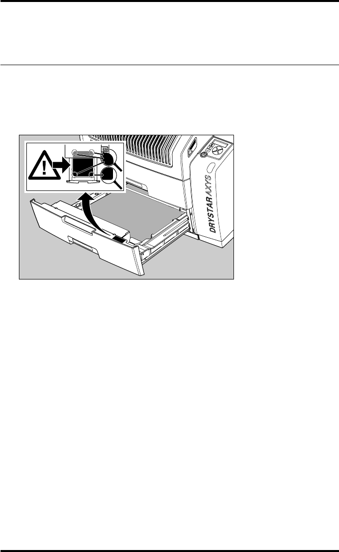
8Tear the plastic strip around the film pack.
9Close the input tray.
Note: The Drystar AXYS resumes printing as soon as the tray is closed.
Note: Loading instructions are also available on the input tray cover.
Note: Never load another film format when the input tray is not empty.
Intermediate changing of film formats increases the risk for dust, which can
damage the thermal print head (TPH).
Note: The system performs an automatic calibration when the film format has
been changed.
Note: When a film job cannot be done because the tray to which the job is assigned
is empty, then the printer will check if the films in the other tray can be used for
this and other print jobs in the print queue. The printer will skip the print jobs that
cannot be done and will resume them later.
Note: When a film sheet is inserted wrongly in the input tray, then the printer will
print on the back-side (non-emulsion side). As a result, a film jam occurs.
Note: The operator will be informed of this back side printing and will be asked to
remove the film jam (refer to “Clearing of film jams” on page 129) and to check
whether the loading procedure was followed correctly (refer to “Film loading
procedure” on page 79).
WARNING: Never reuse a jammed film. Refer to “Clearing of film jams”
on page 129.
83
2852 A EN 20070205
DRYSTAR AXYS
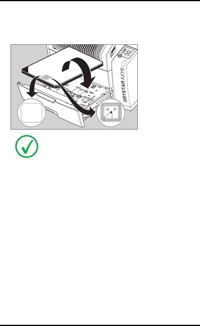
Checking the correct position of a
film in the input tray
You can verify that the film is properly loaded by watching the lower right cor-
ner of the films in the input tray. The rounding of this corner should be smaller
than the other three corners. This is also indicated on the sticker at the right
side of the input tray cover.
84 2852 A EN 20070205
DRYSTAR AXYS
When the tray is closed, the Film Identification tag is read and the printer set-
tings are automatically adjusted if the film properties have changed. The Film
Identification tag is located on the protective sheet on the backside of the film
pack. The figure below shows the film pack upside down.
Note: For some new film types, the Film Identification tag will be covered by a
sticker and therefore will not be visible.

4 Advanced operation
(Key-operator mode)
This chapter consists of the following topics:
❑Overview of key-operator functions
❑Quality Control for general radiography applications (DT 2 B & DT 2 C)
❑Quality control for mammography application (DT 2 Mammo)
(optional)
❑Preventive maintenance schedule
❑Cleaning the exterior
❑Cleaning the print head
❑Troubleshooting checklist
❑Clearing of film jams
❑Film identification problems
86 2852 A EN 20070205
DRYSTAR AXYS
Overview of key-operator functions
The key-operator menus make it possible to use the Drystar AXYS advanced
functions.
For general information on the key functions of the Drystar AXYS, refer to
“Overview of user interface controls” on page 15.
The Drystar AXYS features the following functions on the main menu level of
the key-operator mode:
Note: These functions are describedin detail in the Drystar 5302 advanced
functions.
Menu item Function
Page
(Ref.
manual)
Show settings To consult the current settings of the printer. 95
Change settings To change the current settings of the printer. 105
Print image
To print one of the Drystar AXYS test images.
To load and print images from an external
CF-card.
139
Save configuration To make a back-up of the printer settings. 145
Restore
configuration To restore the back-up of the printer settings. 151
Calibration To calibrate the printer. 159
Service actions To view error, repair and maintenance data. 168
Quality Control
To control with a daily procedure the image
quality respectively of general radiography &
mammography (optional) applications.
87 & 104
(this
manual)
Installation To install or update the Drystar AXYS
software. 203
Note: Refer to the indicated page of the Drystar AXYS Reference manual for
an explanation of the function and the appropriate procedures.
87
2852 A EN 20070205
DRYSTAR AXYS
Quality Control for general
radiography applications (DT 2 B &
DT 2 C)
In order to establish and maintain consistent image quality, a regular evaluation
of image quality is advised.
The Drystar AXYS contains an automatic QC procedure for general radiography
applications and has been designed to comply with the grayscale reproduction
constancy test, according to the international standard IEC 1223-2-4. If the
option for the mammography application is activated, another QC procedure is
available for the mammography application (refer to “Quality control for mam-
mography application (DT 2 Mammo) (optional)” on page 104. In this chapter
we will discuss how to control the quality of general radiography applications.
Local Regulations may require other procedures.
The Drystar AXYS Hard copy quality control procedure consists of two main
steps:
QBefore initial use, establishing a number of reference values that will be used
for further follow-up and verifying initial image quality.
Refer to “Establishing the reference values and verifying image quality for gen-
eral radiography applications (DT 2 B and DT 2 C)” on page 88.
QAfter establishing these values, performing regular daily, weekly and annual
quality tests.
Refer to “Quality Control for general radiography applications (DT 2 B &
DT 2 C)” on page 87.
The results of these tests are recorded on Quality Control Charts.
The QC image (Refer to “QC test image for general radiography applications
(DT 2 B and DT 2 C)” on page 90) has several additional fields where the QC
data can be filled in. This image should be filed as part of the QC procedure.
For more information, please refer to “Quality Control Charts” on page 149.
Note: Repeat the two main steps of the Hard Copy quality procedures for
each input tray loaded with DT 2 B and/or DT 2 C films.

88 2852 A EN 20070205
DRYSTAR AXYS
Establishing the reference values
and verifying image quality for
general radiography applications
(DT 2 B and DT 2 C)
After installation of a new Drystar AXYS and before initial use you must estab-
lish Quality Control aim values. These values will be used as the base line for
comparison when daily Quality Control is done. These values should be deter-
mined again after major service, repair or software update.
The following Quality Control aim values must be determined:
QThe daily operating density levels. Refer to “Establishing the daily operating ref-
erence density levels for general radiography applications (DT 2 B and DT 2 C)”
on page 91.
QDrystar AXYS image geometry. Refer to “Establishing the image geometry refer-
ence values for general radiography applications (DT 2 B and DT 2 C)” on
page 95.
Once Quality Control aim values are established you must evaluate the Spatial
Resolution, the Artifact Levels and the Low Contrast Visibility to determine if
the image quality is acceptable. Refer to “Verifying Acceptable Spatial Resolu-
tion, Artifact Levels and Low Contrast Visibility for general radiography applica-
tions (DT 2 B and DT 2 C)” on page 96.
The Quality Control aim values, the Spatial Resolution and Artifact Levels and
the Image Geometry values are all recorded on the Quality Control charts. Refer
to “Charts for general radiography QC” on page 150.

89
2852 A EN 20070205
DRYSTAR AXYS
On these charts, the following test conditions are also recorded:
QThe type and serial number of the Drystar AXYS.
QThe type and emulsion number of the film used to determine the reference val-
ues.
QThe type of densitometer used.
QThe time (day, month, year) that the values were established.
WARNING: Before you can establish the daily operating levels, the
Drystar AXYS must be switched on for at least 15 minutes and it
must be calibrated as well.
WARNING: Refer to “Switching on the Drystar AXYS” on page 48.
90 2852 A EN 20070205
DRYSTAR AXYS
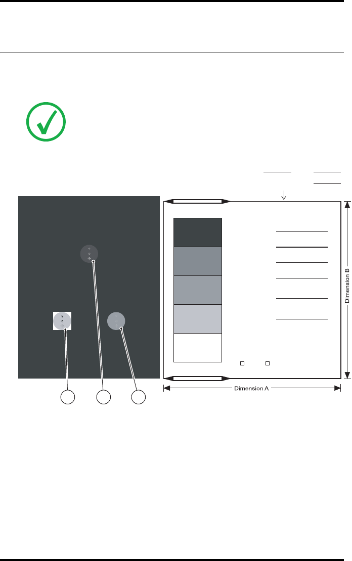
QC test image for general radiography applications
(DT 2 B and DT 2 C)
The QC image has several additional fields where the QC data can be filled in.
This image should be filed as part of the QC procedure.
Note: Note that the dimensions A and B are not indicated on the printed
film.
Lo DBase + Fog Max DHi DMid D
Lo D
Sets of dots visible?
Yes
Base
+ Fog
DD
Density Difference
(Hi D - Lo D)
Weekly spatial
Resolution test
Daily density tests
Geometry test
Max D
Hi D
Mid D
Identification
Quality Control Test Image
Initials: Date:
Time:
No
2 31
91
2852 A EN 20070205
DRYSTAR AXYS
Establishing the daily operating reference density
levels for general radiography applications (DT 2 B
and DT 2 C)
This procedure enables you to establish the base line values for:
QLow density
QMid density
QHigh density
Procedure
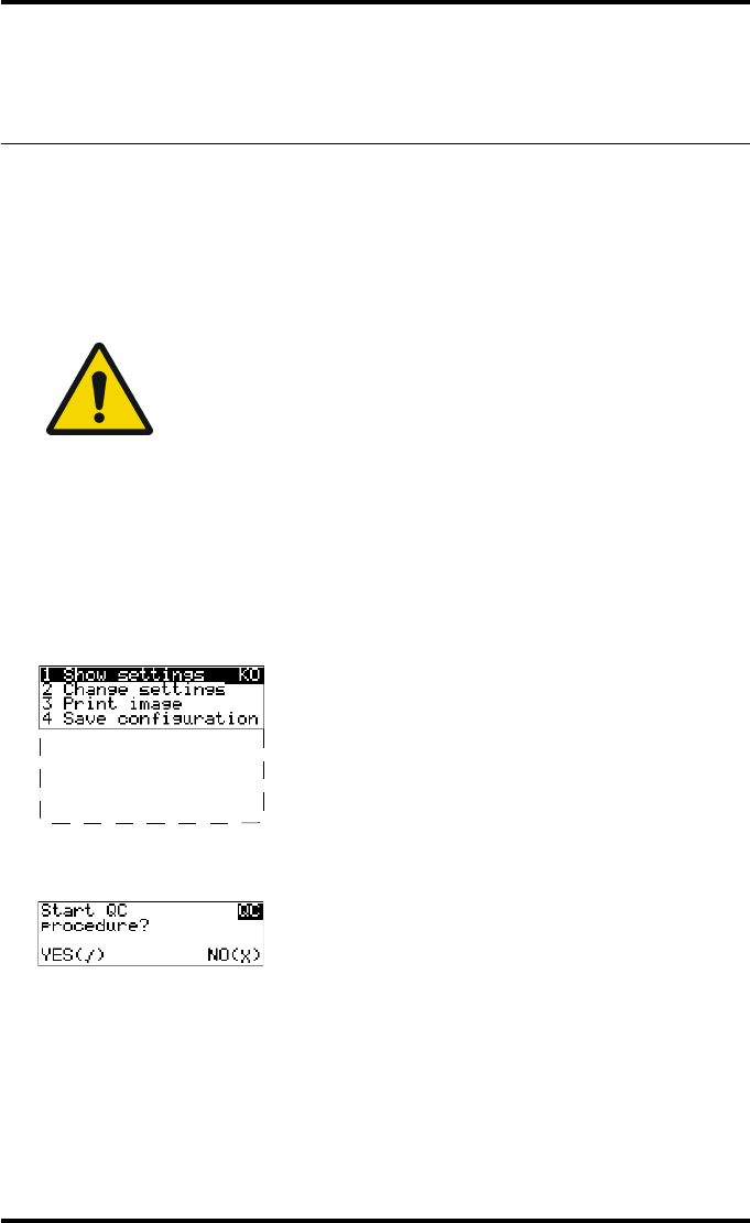
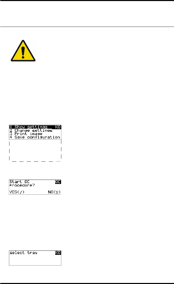
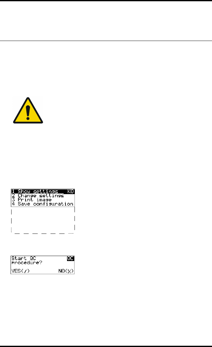
1Press the Key-operator key to enter the Key-operator mode.
2Press the down key seven times, followed by the confirm key to select ‘Quality
Control’.
A confirmation screen appears:
WARNING: The densitometer of the Drystar AXYS is calibrated at
installation. Authorized service personnel should recalibrate the
densitometer annually or after major service or repair.
5 Restore config.
6 Calibration
7 Service Actions
8 Quality Control
9 Installation
92 2852 A EN 20070205
DRYSTAR AXYS
3Do one of the following:
•Press the Confirm key (YES) to start the QC procedure and proceed with step 4.
•Press the Escape key (NO) to quit.
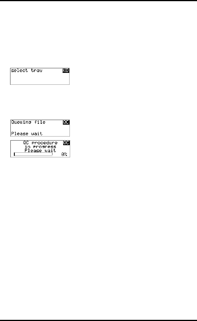
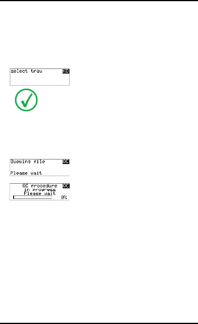
4Define the tray for printing.
The ‘Select tray’ screen appears:
5Press the Up/Down arrow keys to select the desired tray, followed by the Con-
firm key.
The following screens appear successively:
The Drystar AXYS will automatically print the QC test image.
1.Upper tray
2.Lower tray
93
2852 A EN 20070205
DRYSTAR AXYS
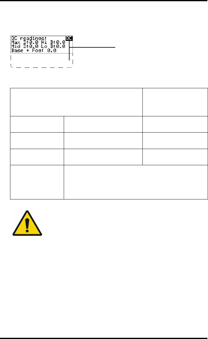
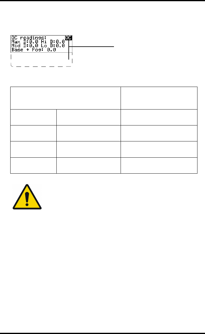
6After the image is printed, the system will display all measured optical density
values:
The displayed values (that have to be monitored) represent the following steps on the
test film:
7Record the low, mid and high density levels on Chart 1 (‘DrystarAXYS Determi-
nation of Operating Levels’). Refer to “Quality Control Charts” on page 149.
8Press the Confirm key to return to the main menu.
9Repeat step 1 through 8 once a day for five consecutive days, as indicated on the
Drystar AXYS Chart 1.
Operating Level
Value (Macbeth units)
(according to
IEC 1223-2-4 or
better)
Low density the density value of the low
density step 0,4 ± 0,05
Mid density the density value of the mid
density step 1,2 ± 0,15
High density the density value of the high
density step 2,0 ± 0,2
Base + Fog,
Density difference
(DD),
Maximum density
(Max D)
These values are displayed but not important for the QC
procedure for general radiography applications.
WARNING: If the mid density value does not meet or exceeds the
recommended values, the reason must be found and the problem
solved before any further clinical films can be printed.
WARNING: Refer to “Preventive maintenance schedule” on
page 121 and “Maintaining image quality and resolving image
quality problems” on page 258 (Reference manual), or call your
local Agfa service organization.
DD: 1.56
(Densitometer=MB924)
The density levels are displayed, e.g:
Max D: 3.2 Hi D: 1.91
Mid D: 1.13 Lo D: 0.35
Base+Fog: 0.19
DD: 1.56

94 2852 A EN 20070205
DRYSTAR AXYS
10 Calculate the average value of the densities from the five images. These values
represent operating levels, or aim values, for each density.
11 Record the respective aim (average) values as the ‘Operating levels’ on Charts
2A and 2B (‘Drystar AXYS Daily Density Control Chart’). Refer to “Quality Con-
trol Charts” on page 149.
The calculated ‘Operating levels’ should be as following:
12 These charts will be used for the daily quality test. For more information, refer
to “Performing the daily QC test for general radiography applications (DT 2 B
and DT 2 C)” on page 99.
Operating Level Value
(according to IEC 1223-2-4 or better)
Low density 0,4 ± 0,05
Mid density 1,2 ± 0,15
High density 2,0 ± 0,2

95
2852 A EN 20070205
DRYSTAR AXYS
Establishing the image geometry reference values
for general radiography applications (DT 2 B and
DT 2 C)
Procedure
1Print the QC test image or use the previously printed test image.
For an example, see “QC test image for general radiography applications (DT 2 B and
DT2C)” on page 90.
2To determine the reference values for geometry, measure the distances
A and B of the geometric square on the test image.
3Record these values as reference dimensions Aref and Bref on Chart 4
(‘Drystar AXYS Geometric Consistency Control Chart’). Refer to “Quality Con-
trol Charts” on page 149.
These charts will be used for the annual quality test. For more information, refer to
“Performing the Annual QC tests for general radiography applications (DT 2 B and
DT2C)” on page 103.
4Save this film for future reference.
WARNING: Make sure to measure distance A from the left edge of
the left line to the right edge of the right line and distance B from
the upper edge of the upper line to the lower edge of the lower
line.
WARNING: We strongly recommend using a 30 cm (12-inch)
machinist scale with 0.5 mm divisions (1/64 inch).
96 2852 A EN 20070205
DRYSTAR AXYS
Verifying Acceptable Spatial Resolution, Artifact
Levels and Low Contrast Visibility for general
radiography applications (DT 2 B and DT 2 C)
Procedure
1Print the QC Test image or use the previously printed QC Test image used to
establish the daily operating density levels.
2Visually check the QC test image for artifacts: no significant disturbing artifacts
should be visible.
3Check the spatial resolution in each of the three circles (refer to item 1, 2 and 3
on the “QC test image for general radiography applications (DT 2 B and
DT 2 C)” on page 90). Within each circle there are three groups, each consisting
of five dots. All five dots of each group must be visible with a magnifying glass.
The smallest cluster of 5 dots is only visible if the viewing conditions are good.
4Check the Low Contrast Visibility at both the high (100 / 95%) and low end
(0 / 5%) of the density scale. You should be able to see the circle in the square
(refer to item 1 on the “QC test image for general radiography applications
(DT 2 B and DT 2 C)” on page 90 and the upper circle (refer to item 2 on the
“QC test image for general radiography applications (DT 2 B and DT 2 C)” on
page 90.
5Record these values at the top of Chart 3 (‘Drystar AXYS Artifacts and Spatial
Resolution Control Chart’). Refer to “Quality Control Charts” on page 149.
WARNING: Good viewing conditions are important for the correct
interpretation of both diagnostic and test images. Make sure that the light
box intensity (luminance) is between 2000 and 4000 cd/m² (4500 and
6500 °K). Use a magnifying glass and use shutters to collimate. Make sure
the ambient light is low.

97
2852 A EN 20070205
DRYSTAR AXYS
6These charts will be used for the weekly quality test. For more information,
refer to “Performing the Weekly QC tests for general radiography applications
(DT 2 B and DT 2 C)” on page 101.
WARNING: In case of significant artifacts or insufficient spatial
resolution, the reason must be found and the problem solved
before any further clinical films can be printed.
WARNING: Refer to “Preventive maintenance schedule” on
page 121 and “Maintaining image quality and resolving image
quality problems” on page 258 (Reference manual), or call your
local Agfa service organization.

98 2852 A EN 20070205
DRYSTAR AXYS
Performing quality control (QC) tests
for general radiography applications
(DT 2 B and DT 2 C)
The following procedures must be performed daily, weekly or annually as indi-
cated.
The reason for performing quality control tests is to determine if any significant
image quality variation or deterioration has occurred which may require correc-
tive action. Comparing the results of the tests with the reference values previ-
ously established does this.
This procedure allows the operator to take the necessary preventive actions
before any image quality loss can take place.
99
2852 A EN 20070205
DRYSTAR AXYS
Performing the daily QC test for general
radiography applications (DT 2 B and DT 2 C)
Procedure
1Turn on the Drystar AXYS and wait at least for 15 minutes. Refer to “Switching
on the Drystar AXYS” on page 48.
2Press the Key-operator key to enter the Key-operator mode.
3Press the down key seven times, followed by the ok key to select ‘QC’.
A confirmation screen appears:
4Do one of the following:
•Press the Confirm key (YES) to start the QC procedure and proceed with step 5.
•Press the Escape key (NO) to quit.
5Define the tray for printing.
The ‘Select tray’ screen appears:
WARNING: This test must be performed every day before any clinical film
can be processed.
5 Restore config.
6 Calibration
7 Service Actions
8 Quality Control
9 Installation
1.Upper tray
2.Lower tray
100 2852 A EN 20070205
DRYSTAR AXYS
6Press the Up/Down arrow keys to select the desired tray, followed by the Con-
firm key.
The following screens appear successively:
The Drystar AXYS will automatically print the QC test image.
After the image is printed, the system will display all measured optical density values:
7Record the low, mid and high density values on Charts 2A and 2B
(‘Drystar AXYS Daily Density Control Chart’). Also record the date and time of
the test on the charts and on the QC test images. Refer to “Quality Control
Charts” on page 149.
8Press the Confirm key to return to the main menu.
WARNING: In case the measure results are not within the aim
values, the reason for the unacceptable density variations must be
identified and resolved before any further clinical films can be
processed. This may include repeating the film calibration
procedure.
WARNING: For possible causes of non-compliance and the
respective actions, refer to “Preventive maintenance schedule” on
page 121 and “Maintaining image quality and resolving image
quality problems” on page 258 (Reference manual).
DD: 1.56
(Densitometer=MB924)
The density levels are displayed, e.g:
Max D: 3.2 Hi D: 1.91
Mid D: 1.13 Lo D: 0.35
Base+Fog: 0.19
DD: 1.56

101
2852 A EN 20070205
DRYSTAR AXYS
Performing the Weekly QC tests for general
radiography applications (DT 2 B and DT 2 C)
Spatial Resolution, Artifact Test and Low Contrast Visibility
To identify artifacts and verify spatial resolution you must perform the follow-
ing test weekly or as needed for troubleshooting image quality problems.
Procedure
1First, print out the QC test image. Refer to “Performing the daily QC test for gen-
eral radiography applications (DT 2 B and DT 2 C)” on page 99.
2Check the QC test image visually for artifacts: no significant disturbing artifacts
should be visible.
3Check the spatial resolution in each of the three circles (refer to item 1, 2 and 3
on the “QC test image for general radiography applications (DT 2 B and
DT 2 C)” on page 90). Within each circle there are three groups, each consisting
of five dots. All five dots of each group must be visible with a magnifying glass.
The smallest cluster of 5 dots is only visible if the viewing conditions are good.
4Check the Low Contrast Visibility at both the high (100 / 95%) and low end
(0 / 5%) of the density scale. You should be able to see the circle in the square
(refer to item 1 on the “QC test image for general radiography applications
(DT 2 B and DT 2 C)” on page 90 and the upper circle (refer to item 2 on the
“QC test image for general radiography applications (DT 2 B and DT 2 C)” on
page 90).
5Record these values on Chart 3 (‘Drystar AXYS Artifacts and Spatial Resolution
Control Chart’).
WARNING: Good viewing conditions are important for the correct
interpretation of both diagnostic and test images. Make sure that the light
box intensity (luminance) is between 2000 and 4000 cd/m² (4500 and
6500 °K). Use a magnifying glass and use shutters to collimate. Make sure
the ambient light is low.

102 2852 A EN 20070205
DRYSTAR AXYS
WARNING: In case of significant artifacts, insufficient spatial
resolution or failure of any other recommended QC tests, the
cause of the problem must be identified, and corrective action
must be taken before the Drystar AXYS can be used for any further
clinical imaging.
WARNING: Refer to “Preventive maintenance schedule” on
page 121 and “Maintaining image quality and resolving image
quality problems” on page 258 (Reference manual), or call your
local Agfa service organization.
103
2852 A EN 20070205
DRYSTAR AXYS
Performing the Annual QC tests for general
radiography applications (DT 2 B and DT 2 C)
Geometric Consistency Test
To be able to notice fluctuations in image size and aspect ratio, you must per-
form this procedure once a year.
Procedure
1First, perform the daily test.
2Use the QC test image of the weekly test and measure the dimensions A and B of
the geometric square. Refer to “Establishing the image geometry reference val-
ues for general radiography applications (DT 2 B and DT 2 C)” on page 95.
3Record these values as measured dimensions A and B on Chart 4 (‘Drystar AXYS
Geometric Consistency Control Chart’).
4Compare the measured A and B dimensions with the reference dimension val-
ues, Aref and Bref on Chart 4 (‘Drystar AXYS Geometric Consistency Control
Chart’).
The differences between measured dimensions of A and B and the reference values
Aref and Bref should be less than or equal to 1.0%.
5Check for image distortion.
6Calculate the aspect ratio by dividing A by B.
The result must be 1 +/- 0.01
WARNING: Make sure to measure distance A from the left edge of
the left line to the right edge of the right line and distance B from
the upper edge of the upper line to the lower edge of the lower
line.
WARNING: We strongly recommend using a 30 cm (12-inch)
machinist scale with 0.5 mm divisions (1/64 inch).
WARNING: If the image size or distortion values are outside of limits,
contact Agfa service to resolve the problem.
104 2852 A EN 20070205
DRYSTAR AXYS
Quality control for mammography
application (DT 2 Mammo) (optional)
In order to establish and maintain consistent image quality, a regular evaluation
of the image quality is advised.
The Drystar AXYS contains an automatic QC procedure for general radiography
applications (refer to “Quality Control for general radiography applications
(DT 2 B & DT 2 C)” on page 87). If the option for the mammography application
is activated, another QC procedure is available for the mammography applica-
tion. This QC procedure has been designed to comply with the NEMA Standards
publication XR 23-2006. In this chapter we will discuss how to control the qual-
ity of mammography applications. This procedure is automatically selected
when there is Mammo media in the input tray.
Local Regulations may require other procedures.
The Drystar AXYS Hard Copy quality control procedures consist of two main
steps:
QBefore initial use, establishing a number of reference values that will be used
for further follow-up and verifying initial image quality.
QRefer to “Establishing the daily operating reference density levels for mammog-
raphy application (DT 2 Mammo) (optional)” on page 108.
QAfter establishing these values, performing regular daily, weekly and annual
quality tests.
QRefer to “Performing quality control (QC) tests for mammography application
(DT 2 Mammo) (optional)” on page 115.
The results of these tests are recorded on Quality Control Charts.
The QC image (refer to the “QC test image for mammography applications
(DT 2 Mammo) (optional)” on page 107) has several additional fields where
the QC data can be filled in. This image should be filed as part of the QC proce-
dure.
For more information, please refer to “Quality Control Charts” on page 149.
Note: Repeat the two main steps of the Hard Copy quality procedures for
each input tray loaded with DT 2 Mammo films.

105
2852 A EN 20070205
DRYSTAR AXYS
Establishing the reference values
and verifying image quality for
mammography application
(DT 2 Mammo) (optional)
After installation of a new Drystar AXYS and before initial use you must estab-
lish Quality Control aim values. These values will be used as the base line for
comparison when daily Quality Control is done. These values should be deter-
mined again after major service, repair or software update.
The following Quality Control aim values must be determined:
QThe daily operating density levels. Refer to “Establishing the daily operating ref-
erence density levels for mammography application (DT 2 Mammo) (optional)”
on page 108.
QDrystar AXYS image geometry. Refer to “Establishing the image geometry refer-
ence values for mammography application (DT 2 Mammo) (optional)” on
page 112.
Once Quality Control aim values are established you must evaluate the Spatial
Resolution, the Artifact Levels and the Low Contrast Visibility to determine if
the image quality is acceptable. Refer to “Verifying Acceptable Spatial Resolu-
tion and Artifact Levels and Low Contrast Visibility for mammography applica-
tion (DT 2 Mammo) (optional)” on page 113.
The Quality Control aim values, the Spatial Resolution and Artifact Levels and
the Image Geometry values are all recorded on the Quality Control charts. Refer
to “Charts for mammography QC (optional)” on page 155.

106 2852 A EN 20070205
DRYSTAR AXYS
On these charts, the following test conditions are also recorded:
QThe type and serial number of the Drystar AXYS.
QThe type and emulsion number of the film used to determine the reference val-
ues.
QThe type of densitometer used.
QThe time (day, month, year) that the values were established.
WARNING: Before you can establish the daily operating levels, the
Drystar AXYS must be switched on for at least 15 minutes and it
must be calibrated as well.
WARNING: Refer to “Switching on the Drystar AXYS” on page 48.

107
2852 A EN 20070205
DRYSTAR AXYS
QC test image for mammography applications
(DT 2 Mammo) (optional)
The QC image has several additional fields where the QC data can be filled in.
This image should be filed as part of the QC procedure.
Note: Note that the dimensions A and B are not indicated on the printed
film.
Lo DBase + Fog Max DHi DMid D
Lo D
Sets of dots visible?
Yes
Base
+ Fog
DD
Density Difference
(Hi D - Lo D)
Weekly spatial
Resolution test
Daily density tests
Geometry test
Max D
Hi D
Mid D
Identification
Quality Control Test Image
Initials: Date:
Time:
No
2 31
108 2852 A EN 20070205
DRYSTAR AXYS
Establishing the daily operating reference density
levels for mammography application
(DT 2 Mammo) (optional)
This procedure enables you to establish the base line values for:
QLow density
QMid density
QHigh density
Procedure
1Press the Key-operator key to enter the Key-operator mode.
2Press the down key seven times, followed by the confirm key to select ‘Quality
Control’.
A confirmation screen appears:
WARNING: The densitometer of the Drystar AXYS is calibrated at
installation. Authorized service personnel should recalibrate the
internal densitometer annually or after major service or repair.
5 Restore config.
6 Calibration
7 Service Actions
8 Quality Control
9 Installation
109
2852 A EN 20070205
DRYSTAR AXYS
3Do one of the following:
•Press the Confirm key (YES) to start the QC procedure and proceed with step 4.
•Press the Escape key (NO) to quit.
4Define the tray for printing.
The ‘Select tray’ screen appears:
5Press the Up/Down arrow keys to select the desired tray, followed by the Con-
firm key.
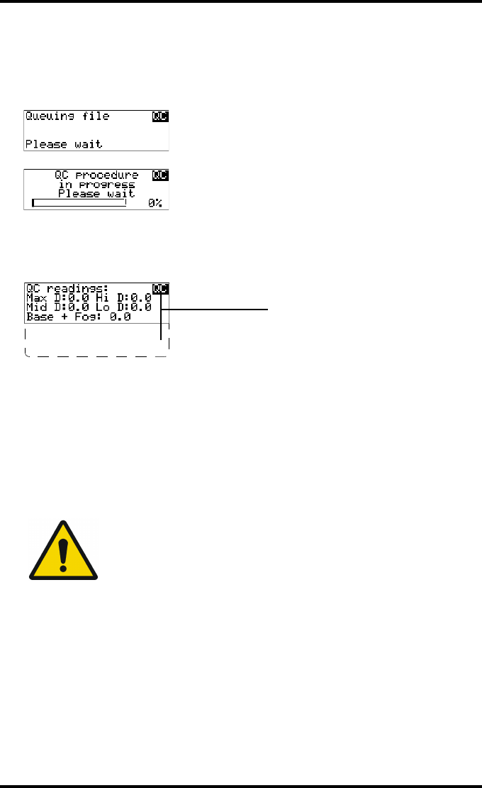
The following screens appear successively:
The Drystar AXYS will automatically print the QC mammography test image.
Note: When controlling the Drystar AXYS via a remote PC, The ‘Select input
tray’ screen is preceded by a screen, which allows you to:
Note: Start the quality control procedure immediately,
Note: Edit additional data for the last quality control measuring.
1.Upper tray
2.Lower tray
110 2852 A EN 20070205
DRYSTAR AXYS
6After the image is printed, the system will display all measured optical density
values:
The displayed values (that have to be monitored) represent the following steps on the
test film:
7Record the density levels on Chart 1 (‘DrystarAXYS Determination of Operating
Levels’). Refer to “Charts for mammography QC (optional)” on page 155.
8Press the Confirm key to return to the main menu.
9Repeat steps 1 through 8 once a day for five consecutive days, as indicated on
the Drystar AXYS Chart 1.
10 Calculate the average value of the densities from the five images. These values
represent operating levels or aim values, for each density.
Operating Level
Value (Macbeth units)
(according to NEMA
standards XR 23-2006)
Base + Fog the density value of the
Base + Fog step 0. 22 ± 0.03
Low density the density value of the
low density step 0.45 ± 0.07
Mid density the density value of the
mid density step 1.20 ± 0.15
High density the density value of the
high density step 2.20 ± 0.15
WARNING: If the mid density value does not meet or exceeds the
recommended values, the cause must be found and the problem
solved before any further clinical films can be printed.
WARNING: Refer to “Preventive maintenance schedule” on
page 121 and “Maintaining image quality and resolving image
quality problems” on page 258 (Reference manual), or call your
local Agfa service organization.
DD: 1.56
(Densitometer=MB924)
The density levels are displayed, e.g:
Max D: x.x Hi D: 2.23
Mid D: 1.13 Lo D: 0.4
Base+Fog: 0.20
DD: x.xx

111
2852 A EN 20070205
DRYSTAR AXYS
11 Record the respective aim (average) values as the ‘Operating levels’ on Charts
2A and 2B (‘Drystar AXYS Daily Density Control Chart’). Refer to “Charts for
mammography QC (optional)” on page 155.
The calculated ‘Operating levels’ should be as follows:
12 These charts will be used for the daily quality test. For more information, refer
to “Performing the daily QC test for mammography application (DT 2 Mammo)
(optional)” on page 116.
Operating Level Value (Macbeth units)
(according to NEMA standards XR 23-2006)
Base + Fog 0. 22 ± 0.03
Low density 0.45 ± 0.07
Mid density 1.20 ± 0.15
High density 2.20 ± 0.15
112 2852 A EN 20070205
DRYSTAR AXYS
Establishing the image geometry reference values
for mammography application (DT 2 Mammo)
(optional)
Procedure
1Print the QC mammography test image or use the previously printed test image.
For an example, see “QC test image for mammography applications (DT 2 Mammo)
(optional)” on page 107.
2To determine the reference values for geometry, measure the distances A and B
of the geometric square on the test image.
3Record these values as reference dimensions Aref and Bref on Chart 4
(‘Drystar AXYS Geometric Consistency Control Chart’). Refer to “Charts for
mammography QC (optional)” on page 155.
These charts will be used for the annual quality test. For more information, refer to
“Performing the Annual QC tests for mammography application (DT 2 Mammo)
(optional)” on page 120.
4Save this film for future reference.
WARNING: Make sure to measure distance A from the left edge of
the left line to the right edge of the right line and distance B from
the upper edge of the upper line to the lower edge of the lower
line.
WARNING: We strongly recommend using a 30 cm (12-inch)
machinist scale with 0.5 mm divisions (1/64 inch).

113
2852 A EN 20070205
DRYSTAR AXYS
Verifying Acceptable Spatial Resolution and
Artifact Levels and Low Contrast Visibility for
mammography application (DT 2 Mammo)
(optional)
Procedure
1Print the QC mammography test image or use the previously printed QC mam-
mography test image used to establish the daily operating density levels.
2Visually check the QC test image for artifacts: no significant disturbing artifacts
should be visible.
3Check the spatial resolution in each of the three ovals. Within each oval there
are three groups, each having five dots. All five dots of each group must be visi-
ble with a magnifying glass. The smallest cluster of 5 dots is only visible if the
viewing conditions are good.
4Check the Low Contrast Visibility at both the high (100 / 95%) and low end
(0 / 5%) of the density scale. You should be able to see the circle in the square
(refer to item 1 on the “QC test image for mammography applications
(DT 2 Mammo) (optional)” on page 107) and the upper circle (refer to item 2
on the “QC test image for mammography applications (DT 2 Mammo)
(optional)” on page 107.
5Record these values at the top of Chart 3 (‘Drystar AXYS Artifacts and Spatial
Resolution Control Chart’).Refer to “Charts for mammography QC (optional)”
on page 155.
WARNING: Good viewing conditions are important for the correct
interpretation of both diagnostic and test images. Make sure that
the light box intensity (luminance) is between 3000 and 6000 cd/
m² (4500 and 6500 °K) for mammography. Use a magnifying glass
and use shutters to collimate. Make sure the ambient light is low.

114 2852 A EN 20070205
DRYSTAR AXYS
6These charts will be used for the weekly quality test. For more information,
refer to “Performing the Weekly QC tests for mammography application
(DT 2 Mammo) (optional)” on page 118.
WARNING: In case of significant artifacts or insufficient spatial
resolution, the cause must be found and the problem solved
before any further clinical films can be printed.
WARNING: Refer to “Preventive maintenance schedule” on
page 121 and “Maintaining image quality and resolving image
quality problems” on page 258 (Reference manual), or call your
local Agfa service organization.

115
2852 A EN 20070205
DRYSTAR AXYS
Performing quality control (QC) tests
for mammography application
(DT 2 Mammo) (optional)
The following procedures must be performed daily, weekly or annually as indi-
cated.
The reason for performing quality control tests is to determine if any significant
image quality variation or deterioration has occurred which may require correc-
tive action. Comparing the results of the tests with the reference values previ-
ously established does this.
This procedure allows the operator to take the necessary preventive actions
before any image quality loss can take place.

116 2852 A EN 20070205
DRYSTAR AXYS
Performing the daily QC test for mammography
application (DT 2 Mammo) (optional)
Procedure
1Turn on the Drystar AXYS and wait at least for 15 minutes. Refer to “Switching
on the Drystar AXYS” on page 48.
2Press the Key-operator key to enter the Key-operator mode.
3Press the down key seven times, followed by the ok key to select ‘QC’.
A confirmation screen appears:
4Do one of the following:
•Press the Confirm key (YES) to start the QC procedure and proceed with step 5.
•Press the Escape key (NO) to quit.
5Define the tray for printing.
The ‘Select tray’ screen appears:
WARNING: This test must be performed every day before any clinical film
can be processed.
5 Restore config.
6 Calibration
7 Service Actions
8 Quality Control
9 Installation
1.Upper tray
2.Lower tray
117
2852 A EN 20070205
DRYSTAR AXYS
6Press the Up/Down arrow keys to select the desired tray, followed by the Con-
firm key.
The following screens appear successively:
The Drystar AXYS will automatically print the QC test image.
After the image is printed, the system will display all measured optical density values:
7Record the Base + Fog, low, mid and high density values on Charts 2A and 2B
(‘Drystar AXYS Daily Density Control Chart’). Also record the date and time of
the test on the charts and on the QC mammography test images. Refer to Refer
to “Charts for mammography QC (optional)” on page 155.
8Press the Confirm key to return to the main menu.
9Press the ok key to return to the main menu.
WARNING: In case the measure results are not within the aim
values, the reason for the unacceptable density variations must be
identified and resolved before any further clinical films can be
processed. This may include repeating the film calibration
procedure.
WARNING: For possible causes of non-compliance and the
respective actions, refer to “Preventive maintenance schedule” on
page 121 and “Maintaining image quality and resolving image
quality problems” on page 258 (Reference manual).
DD: 1.56
(Densitometer=MB924)
The density levels are displayed, e.g:
Max D: x.x Hi D: 2.23
Mid D: 1.13 Lo D: 0.4
Base+Fog: 0.20
DD: x.xx

118 2852 A EN 20070205
DRYSTAR AXYS
Performing the Weekly QC tests for mammography
application (DT 2 Mammo) (optional)
Spatial Resolution, Artifact Test and Low Contrast Visibility
To identify artifacts and verify spatial resolution you must perform the follow-
ing test weekly or as needed for troubleshooting image quality problems.
Procedure
1First, print out the QC mammography test image. Refer to “Performing the daily
QC test for mammography application (DT 2 Mammo) (optional)” on page 116.
2Check the QC test image visually for artifacts: no significant disturbing artifacts
should be visible.
3Check the spatial resolution.
The test film also shows three squares which each contains an oval. These 3 ovals con-
tain 3 groups, each having 5 dots. All five dots of each group must be visible with a
magnifying glass. The smallest cluster of 5 dots is only visible if the viewing conditions
are good.
4Check the Low Contrast Visibility at both the high (100 / 95%) and low end
(0 / 5%) of the density scale. You should be able to see the circle in the square
(refer to item 1 on the “QC test image for mammography applications
(DT 2 Mammo) (optional)” on page 107) and the upper circle (refer to item 2
on the “QC test image for mammography applications (DT 2 Mammo)
(optional)” on page 107).
WARNING: Good viewing conditions are important for the correct
interpretation of both diagnostic and test images. Make sure that the light
box intensity (luminance) is 3000 and 6000 cd/m² (4500 and 6500 °K)
for mammography. Use a magnifying glass and use shutters to collimate.
Make sure the ambient light is low.

119
2852 A EN 20070205
DRYSTAR AXYS
5Record these values on Chart 3 (‘Drystar AXYS Artifacts and Spatial Resolution
Control Chart’). Refer to “Charts for mammography QC (optional)” on
page 155.
WARNING: In case of significant artifacts, insufficient spatial
resolution or failure of any other recommended QC tests, the
cause of the problem must be identified, and corrective action
must be taken before the Drystar AXYS can be used for any further
clinical imaging.
WARNING: Refer to “Preventive maintenance schedule” on
page 121 and “Maintaining image quality and resolving image
quality problems” on page 258 (Reference manual), or call your
local Agfa service organization.
120 2852 A EN 20070205
DRYSTAR AXYS
Performing the Annual QC tests for mammography
application (DT 2 Mammo) (optional)
Geometric Consistency Test
To be able to notice fluctuations in image size and aspect ratio, you must per-
form this procedure once a year.
Procedure
1First, perform the daily test.
2Measure the distances A and B of the geometric square on the QC mammogra-
phy test image. Refer to “Establishing the image geometry reference values for
mammography application (DT 2 Mammo) (optional)” on page 112.
3Record these values as measured distances A and B on Chart 4 (‘Drystar AXYS
Geometric Consistency Control Chart’). Refer to “Charts for mammography QC
(optional)” on page 155.
4Compare the measured A and B dimensions with the reference dimension val-
ues, Aref and Bref on Chart 4 (‘Drystar AXYS Geometric Consistency Control
Chart’). Refer to “Charts for mammography QC (optional)” on page 155.
The differences between the measured dimensions of A and B and the reference val-
ues A ref and B ref should be less than or equal to 1.0%.
5Check for image distortion.
6Calculate the aspect ratio by dividing A by B.
The result must be 1 +/- 0.01
WARNING: Make sure to measure distance A from the left edge of
the left line to the right edge of the right line and distance B from
the upper edge of the upper line to the lower edge of the lower
line.
WARNING: We strongly recommend using a 30 cm (12-inch)
machinist scale with 0.5 mm divisions (1/64 inch).
WARNING: If the image size or distortion values are outside of
limits, contact Agfa service to resolve the problem.
121
2852 A EN 20070205
DRYSTAR AXYS
Preventive maintenance schedule
The Drystar AXYS is designed for trouble-free operation. Maintenance and
cleaning involve only some minor user tasks. Refer to the following pages for
the appropriate cleaning procedure.
Safety guidelines
QDo not lubricate the printer.
QDo not attempt to disassemble the printer.
QDo not touch the resistor line of the print head.
QAlways switch off the Drystar AXYS and disconnect the power cord from the
outlet before carrying out any maintenance work inside the printer.
Interval What to do?
Ad hoc “Cleaning the exterior” on page 122
When image quality tends to
degrade. An appropriate warning
message is displayed.
“Cleaning the print head” on page 123
WARNING: To prevent damage to the printer while performing
maintenance, observe the following safety precautions:
Caution: Film jam removal or cleaning the printer head can be done
without switching the power off. Nevertheless, care should be taken
and the “Safety Directions” on page 43 should be respected.

122 2852 A EN 20070205
DRYSTAR AXYS
Cleaning the exterior
Procedure
1Switch off the Drystar AXYS by following the procedure as described in
“Switching off the Drystar AXYS” on page 63
2Remove the power plug from the socket.
3Wipe the exterior of the printer with a clean, soft, damp cloth.
Use a mild soap or detergent if required but never use an ammonia–based cleaner. Be
careful not to get any liquid in the power cord port.
4Plug in the printer and switch it on by following the procedure as described in
“Switching on the Drystar AXYS” on page 48.
123
2852 A EN 20070205
DRYSTAR AXYS
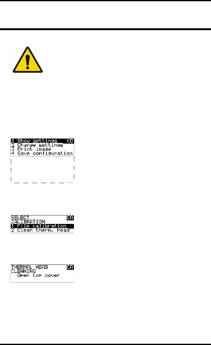
Cleaning the print head
Procedure
1Press the Key-operator key to enter the key-operator mode.
2On the key-operator main menu, press the Down key five times, followed by the
Confirm key to select ‘Calibration’.
3On the Select calibration menu, press the Down key, followed by the Confirm
key to select ‘Clean therm. head’.
4The ‘Thermal head cleaning’ screen will give step-by-step instructions on what
to do:
WARNING: Print head cleaning must be done when image quality
problems occur.
5 Restore config.
6 Calibration
7 Service Actions
8 Quality Control
9 Installation
124 2852 A EN 20070205
DRYSTAR AXYS
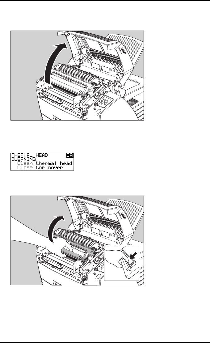
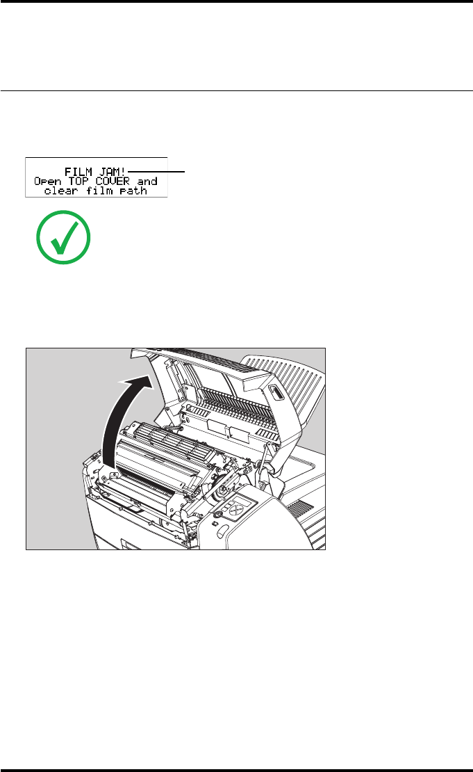
5Open the top cover.
6As soon as the top cover is opened, the ‘Thermal head cleaning’ screen contin-
ues giving the following instructions:
7Open the hold-down bracket.
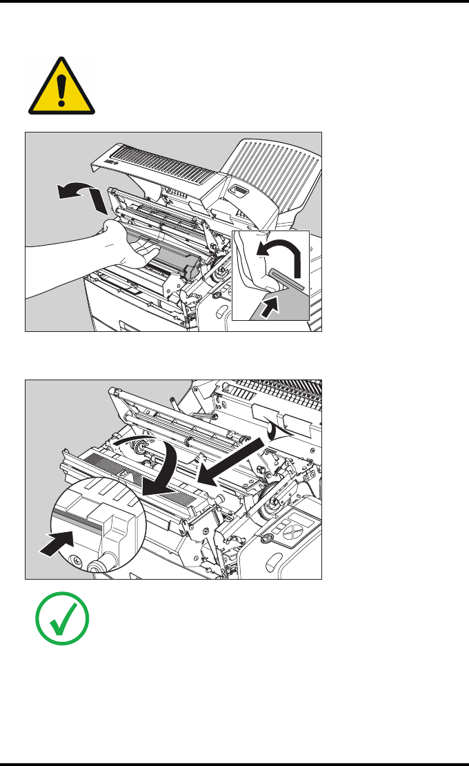
125
2852 A EN 20070205
DRYSTAR AXYS
8Open the print head unit.
9Locate and check on sight the print head resistor line.
WARNING: The print head unit can be warm.
Note: Be careful not to touch the print head resistor line with your fingers.
126 2852 A EN 20070205
DRYSTAR AXYS
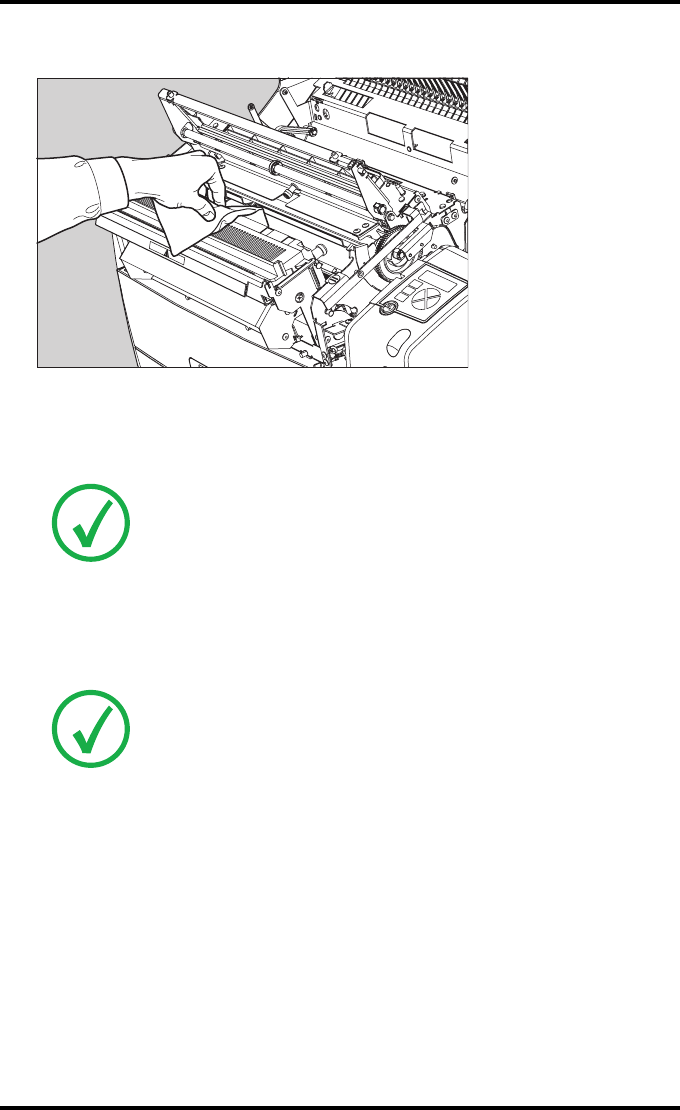
10 Clean the print head resistor line.
Gently pass over the resistor line a few times with a lint free cloth, slightly moistened
with Isopropyl alcohol or Ethanol.
Do this only in one direction, i.e. from left to right, without lifting the cloth.
11 Close the print head unit, the hold-down bracket and finally the top cover.
After you have cleaned the print head resistor line and you have closed the top cover,
you will return automatically to the Select calibration menu (see step 3).
12 Press the Escape key to return to the key-operator main menu.
Note: Do not apply any pressure on the print head because this pressure
may cause damage on the interconnections underneath the print head.
Note: If residue dust is present as part of the cleaning procedure it will
disappear after a few prints.
127
2852 A EN 20070205
DRYSTAR AXYS
Troubleshooting checklist
The table below lists some general problems, which can occur when working
with the Drystar AXYS.
QThe Drystar AXYS does not print.
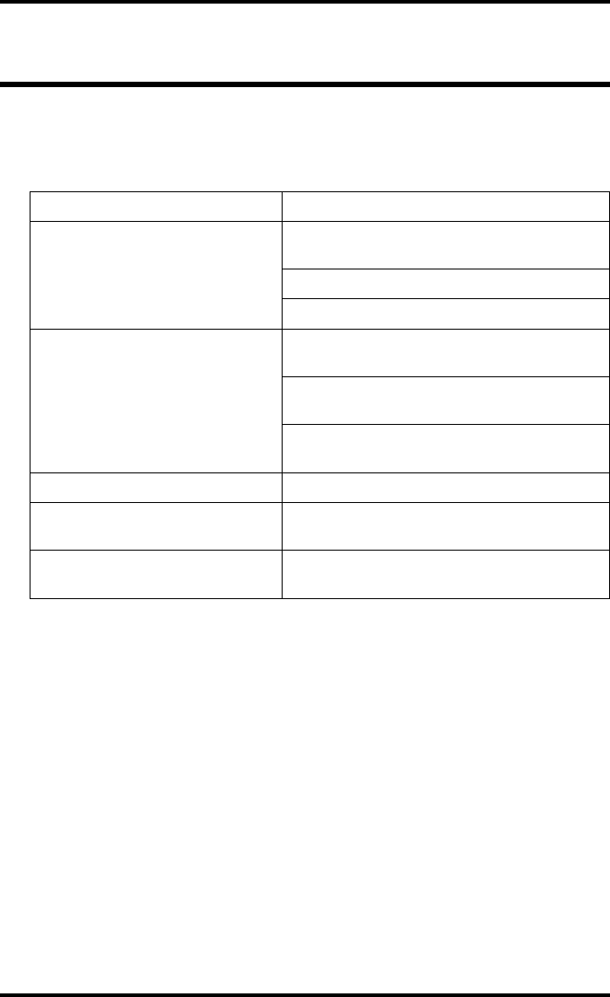
Action Refer to the Reference manual
Check the Drystar AXYS
“Checking the status indicator LED” on
page 241
“Checking the connections” on page 242
“Checking the print queue” on page 244
Remove a jammed film
“Film input tray jams” on page 130 of this
manual
“Film transport jams (clearing from the top)”
on page 133 of this manual
“Unauthorized opening of the printer” on
page 136 of this manual
Resolve error messages “Checking error messages” on page 243
Handle CF-card errors “Checking CF-card error messages” on
page 244
Resolve film identification
problems
“No identification code detected” on
page 138 of this manual
128 2852 A EN 20070205
DRYSTAR AXYS
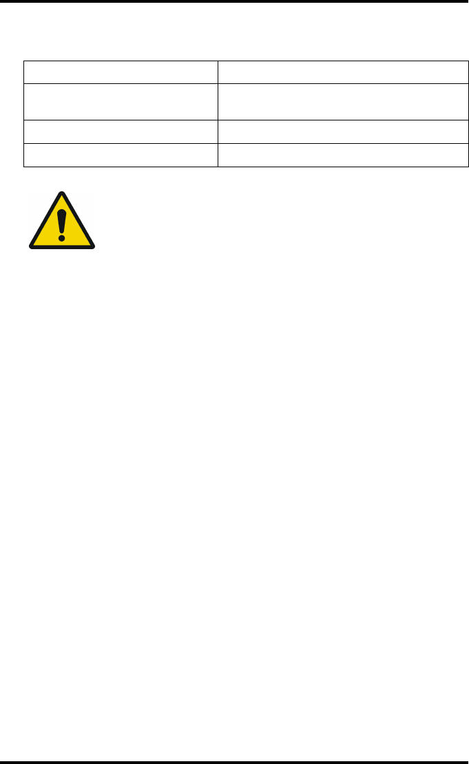
QThe quality of the printed images is bad (printing remains possible).
Action Refer to
Resolve film quality problems “Persistent white dots or lines appear in the
transport direction” on page 261
Resolve warning messages “Warning messages” on page 262
Resolve maintenance messages “Maintenance messages” on page 263
WARNING: Have electrical or mechanical defects repaired by
skilled personnel only!
129
2852 A EN 20070205
DRYSTAR AXYS
Clearing of film jams
A film jam can be situated either:
QIn the input tray section. Refer to “Film input tray jams” on page 130 .
QIn the top section. Refer to “Film transport jams (clearing from the top)” on
page 133 .
Jams can be caused by:
QOpening the top cover or input tray while a film is actually being printed. Refer
to “Unauthorized opening of the printer” on page 136 .
QLoading films incorrectly. Refer to “Film identification problems” on page 137 .
Caution: Film jam removal or cleaning the printer thermal head can be
done without switching the power off. Nevertheless, care should be
taken and the following instructions should be respected:
WARNING: Never reuse a jammed film. This may cause damage to
the thermal head and/or dust problems.
Film feed jams (clearing
from the input tray)
Film transport jams
(clearing from the
top section)
130 2852 A EN 20070205
DRYSTAR AXYS
Film input tray jams
A film jam in the input tray can occur when the Drystar AXYS is opened while a
film is currently printed, or when an individual film is incorrectly inserted in
the input tray. Refer also to “Film identification problems” on page 137 .
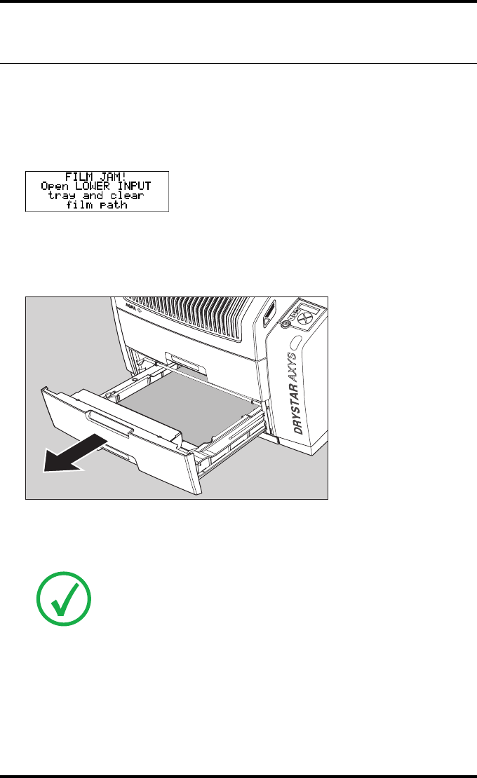
The following screen indicates that a jam occurred in the input tray.
To remove a jammed film in the input tray:
1Open the film input tray.
If a film is jammed, gently remove the sheet. Reposition the film stack in the film tray,
making sure that all the sheets are kept correctly
(refer to “Loading films” on page 76 ).
Note: Never use force to clear the jammed film. If it is not possible to gently
remove the jammed film, call your local service organization.
131
2852 A EN 20070205
DRYSTAR AXYS
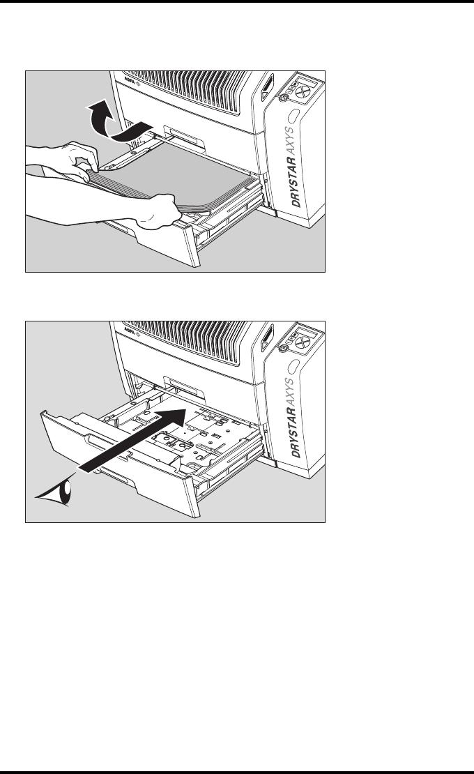
2To get a clear view, it may be necessary to remove any remaining film sheets,
including the protective (white) sheet.
3Check if the film feed section of the input tray is clear.
Reposition the film stack in the film tray, making sure that all the sheets are
kept correctly in place (refer to “Loading films” on page 76).
132 2852 A EN 20070205
DRYSTAR AXYS
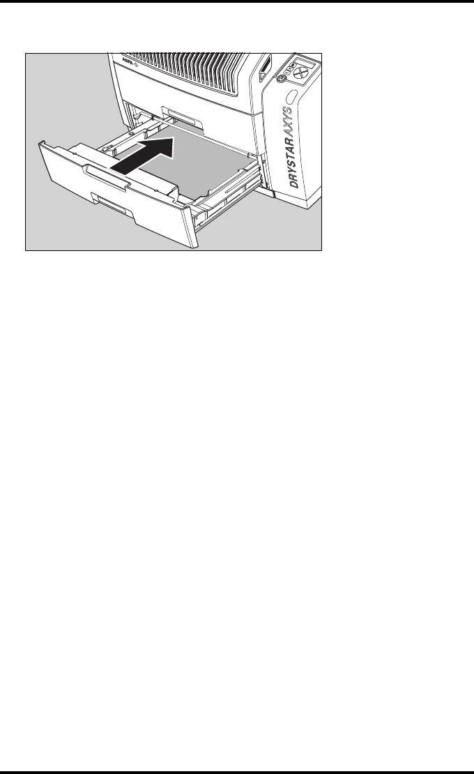
4Close the film input tray.
133
2852 A EN 20070205
DRYSTAR AXYS
Film transport jams (clearing from
the top)
The following screen indicates that a jam occurred in the upper section of the
film transport system.
To remove a jammed film in the transport system:
1Open the top cover.
Note: Please note that instructions for removing a film jam in the transport
section are present on a sticker at the inside of the top cover.
Blinking
134 2852 A EN 20070205
DRYSTAR AXYS
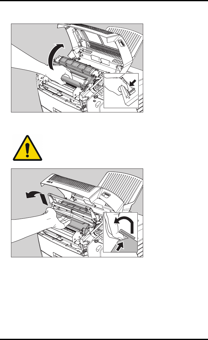
2Open the hold-down bracket.
3Open the print head unit.
WARNING: The print head unit can be warm.
135
2852 A EN 20070205
DRYSTAR AXYS
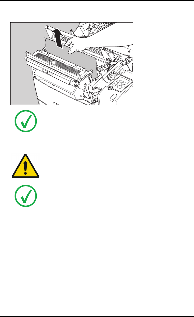
4Gently remove the film sheet(s).
5If the film jam has been cleared, close the printer. You can resume work.
Note: Never use force to clear the jammed film. If it is not possible to gently
remove the jammed film by pressing the transport buttons, proceed with
the procedure as follows.
Note: Verify that no film sheets remain in the print head compartment.
WARNING: Never reuse a jammed film. This may cause damage to
the thermal head and/or dust problems.
Note: If the jam is still not cleared, call your local service organization.
136 2852 A EN 20070205
DRYSTAR AXYS
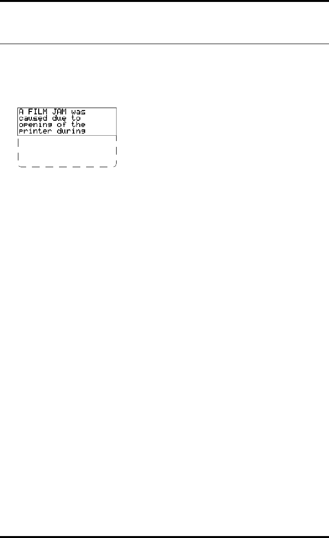
Unauthorized opening of the printer
A jam can be caused by opening the printer covers or one of the input trays
while a film is actually being printed.
The following screen indicates that a jam has occurred:
1Remove the jammed sheet.
Refer to “Clearing of film jams” on page 129 .
2Press the Confirm key to continue.
3Make sure to follow carefully the procedures as described in this manual before
attempting to open the printer.
Refer to “Switching off the Drystar AXYS” on page 63 .
Refer to “Switching off the Drystar AXYS” on page 63 .
printing. Next time
wait until printer
is in "Ready"
condition.

137
2852 A EN 20070205
DRYSTAR AXYS
Film identification problems
When you load a new film pack, the new Film Identification tag is read and the
tray film format and type are set based upon the info in the Film Identification
tag (RF-tag).
This tag is only readable when the film pack is inserted in the correct way.
There are three possible error messages regarding film identification:
Q“No identification code detected” on page 138
Q“Invalid content of Film Identification tag” on page 141
Q“Invalid content of Film Identification tag” on page 141
The following sections describe the solution for each of these problems in more
detail.
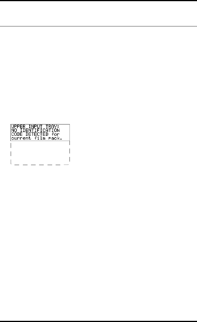
138 2852 A EN 20070205
DRYSTAR AXYS
No identification code detected
This error message appears when the Film Identification tag is not readable.
There are two possible solutions for this problem:
QReload the current film pack or load another film pack
QOverrule the Film Identification tag of the film pack
To reload the current or another film pack
1In case the Drystar AXYS does not start printing after re-inserting a film pack,
first check if this film pack is inserted correctly.
If the Drystar AXYS still does not resume printing, the following message will appear:
2Open the input tray and check again if the film pack is inserted correctly. If you
re-insert the film pack, the Drystar AXYS will perform the same check sequence
until printing is resumed.
Remove and re-insert
film pack -including
protective sheet-
properly. follow
loading instructions
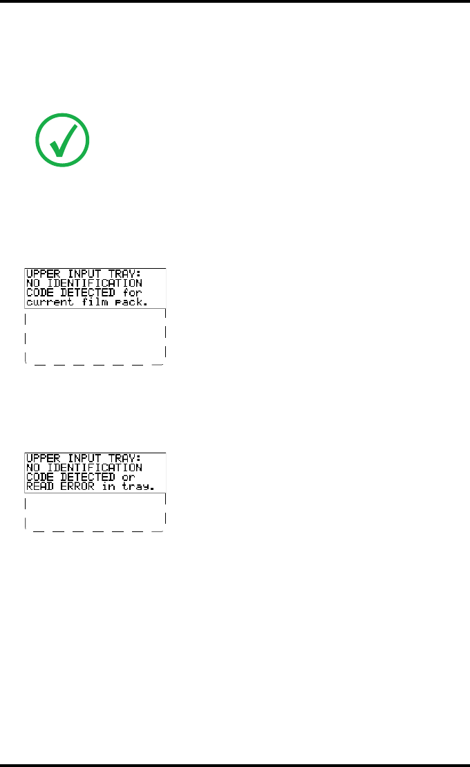
139
2852 A EN 20070205
DRYSTAR AXYS
To overrule the Film Identification tag of the film pack
If the “Overrule RF-tag Reading” setting is active, you can overrule the Film
Identification tag setting of the current film pack. In this case you can continue
printing using a limited Maximum Density.
1In case the Drystar AXYS does not start printing after inserting a new film pack,
check if this film pack is inserted correctly.
If the film pack is inserted correctly and the Drystar AXYS does not resume printing,
the following message will appear:
2To continue with the current (unidentified) film pack, press the Continue but-
ton.
The following message is displayed:
If you wish, you can try again to re-insert the current or an other film pack. Open the
input tray to initiate the loading sequence. If you re-insert a film pack, the
Drystar AXYS will perform the check sequence.
Note: Only your local service organization has the possibility to enable the
“Overrule RF-tag Reading” setting!
Remove and re-insert
film pack -including
protective sheet-
properly. follow
loading instructions
Please INSERT
CURRENT FILM PACK or
call service.
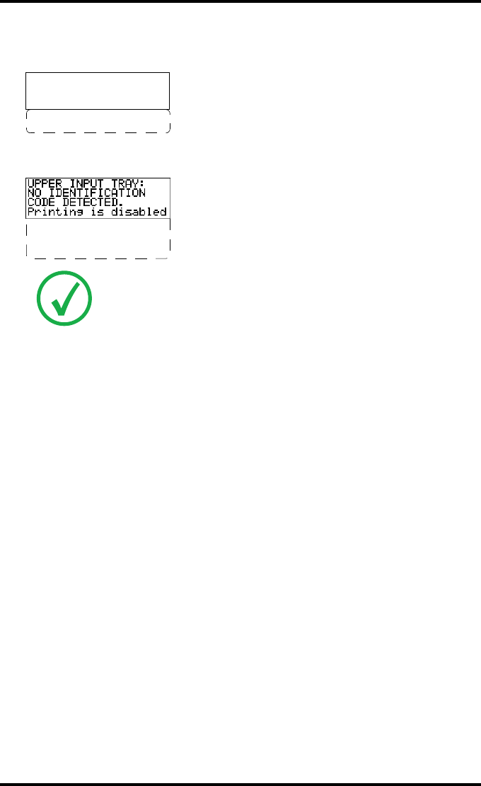
140 2852 A EN 20070205
DRYSTAR AXYS
3Press the Confirm button.
•If the “Overrule RF-tag Reading” Setting is active, the following message is displayed:
•If the “Overrule RF-tag Reading” Setting is not activated, the following message will
be displayed:
4Press the Confirm key again to resume printing using a limited Maximum Den-
sity.
Note: In this case, press the Confirm key to initiate the loading procedure
again or call your local service organization to enable the “Overrule RF-tag
Reading” Setting.
OVERRULE
IDENTIFICATION CODE
IS ACTIVE
Dmax is limited due
to safety reasons
Re-enable printing
by inserting correct
film media pack.
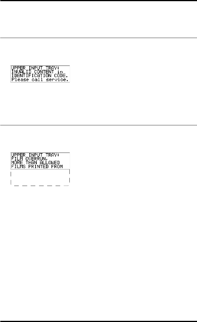
141
2852 A EN 20070205
DRYSTAR AXYS
Invalid content of Film Identification
tag
When you insert a new film pack with invalid content in the Film Identification
tag, the following message is displayed:
Try loading another film pack, or call your local service organization to resolve
this problem.
Film overrun from current pack
The following message is presented when more than 110 copies are printed
from the current film pack:
Reload a new film pack to resolve this problem.
THIS PACK. please
insert other film
pack.

142 2852 A EN 20070205
DRYSTAR AXYS


144 2852 A EN 20070205
DRYSTAR AXYS
Specifications
Product description
Type of product Printer
Commercial name Drystar AXYS
Original seller/manufacturer Agfa-Gevaert N.V.
Labelling
TÜV-, cULus-Certification Mark,
CE-marking
CCC Mark
Dimensions
Dimensions (approx. values in cm)
Unpacked: width 72.8, length 71.5,
height 67.6
Packed: width 89, length 100,
height 80
Weight Unpacked: approx. 90 kg
Packed: approx. 128 kg
RAM memory 512 Mb
Internal mass storage media Hard Disk
External mass storage media Compact Flash Type II
Electrical connection
Operating voltage 100-120 V; 220-240 V AC
No external main fuses
Mains frequency 50/60 Hz

145
2852 A EN 20070205
DRYSTAR AXYS
Network connectivity
Ethernet / connectors RJ45 twisted pair for 10/100Base-TX;
Serial RS232 connection
Network protocols (TCP/IP services) FTP, Telnet, HTTP
Image formats DICOM (Default)
TIFF
Postscript Not available
Power consumption - heat dissipation
During operation 250 W - 900 kJ/h
In stand-by 70 W - 252 kJ/h
Peak power (absolute max. rating) 530 W - 1908 kJ/h
Protection against
Electrical shocks Class 1 (grounded)
Ingress of water IPXØ
Environmental conditions (operation)
Room temperature Between +15°C and +30°C
Relative humidity Between 20% and 75%
Note: Films may not become wet!
Atmospheric pressure 70 kPa - 106 kPa
Environmental storage conditions
Note: Climate conditions for storage are in accordance with EN60721-3-1-
class 1K4.
Room temperature Between -25°C and 55°C (storage)
Relative humidity Between 10% and 100%
Absolute humidity Between 0.1 g/m3 and 35 g/m3
Rate of change of temperature 1°C/min
Atmospheric pressure 70 kPa - 106 kPa
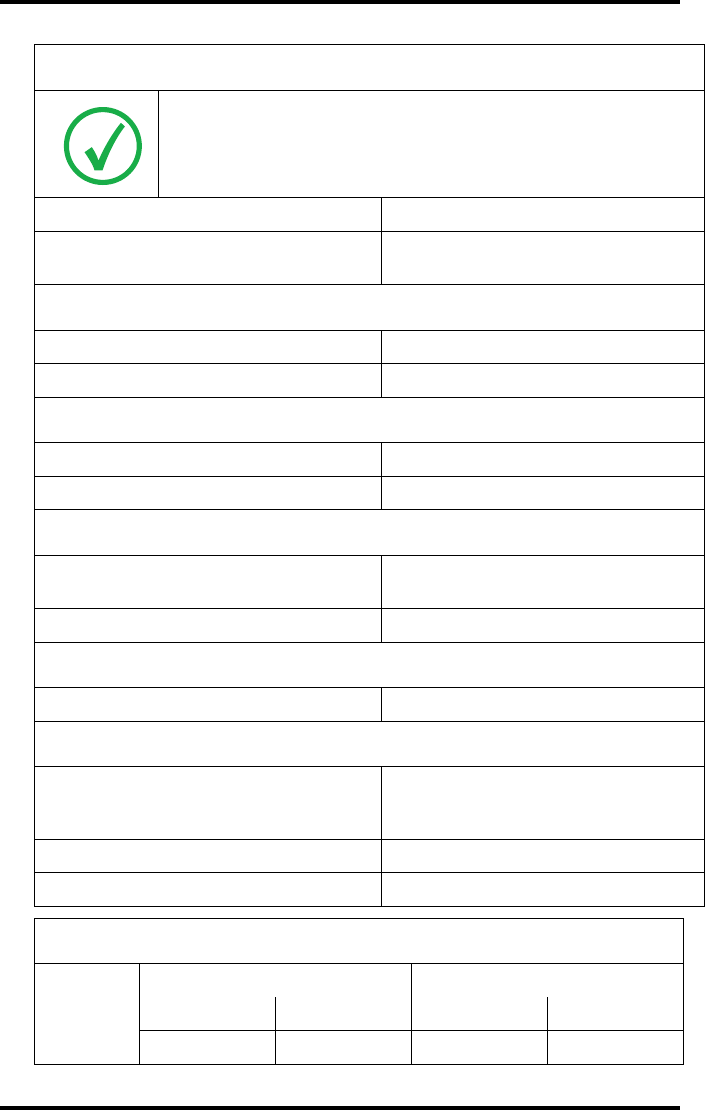
146 2852 A EN 20070205
DRYSTAR AXYS
Environmental transport conditions
Note: Climate conditions for transport are in accordance with
EN60721-3-2-class 2K4.
Temperature Between -40°C and 70°C (transport)
Relative humidity not combined with
rapid temperature changes 95% at +45°C
Noise emission (method of measurement in accordance with DIN 45635 part 19)
During operation Max. 64 dBA
In stand-by Max. 54 dBA
Total acoustic A-weighted noise power
During operation 62 dB ( = 6.4Bel = 6.4B)
In stand-by 53 dB ( = 5.3Bel = 5.3B)
Consumables
Drystar DT 2B and Drystar DT 2C 8x10”, 10x12”, 11x14”, 14x14” and
14x17”film sizes
Drystar DT 2 Mammo (optional) 8x10”, 10x12” and 11x14” film sizes
Print technology
Direct thermal printing
Reliability
Estimated product life
(if regularly serviced and maintained
according to Agfa instructions)
> 5 years
Service interventions Max. 2 interventions / 3 years
Earthquake (standard) Meets the CA requirements
Imaging Array - Diagnostic area - General radiography
8x10”
8” dimensions 10” dimensions
pixels mm pixels mm
3852 192,6 4880 244

147
2852 A EN 20070205
DRYSTAR AXYS
10x12”
10” dimensions 12” dimensions
pixels mm pixels mm
4880 244 5860 293
11x14”
11” dimensions 14” dimensions
pixels mm pixels mm
5376 268,8 6922 346,1
14x14”
14” dimensions 14” dimensions
pixels mm pixels mm
6882 344,1 6882 344,1
14x17”
14” dimensions 17” dimensions
pixels mm pixels mm
6922 346,1 8368 418,4
Imaging Array - Diagnostic area - Mammography (optional)
8x10”
8” dimensions 10” dimensions
pixels mm pixels mm
3828 191,4 4958 247,9
10x12”
10” dimensions 12” dimensions
pixels mm pixels mm
4892 244,6 5810 290,5
11x14”
11” dimensions 14” dimensions
pixels mm pixels mm
5376 268,8 6922 346,1
Imaging Array - Diagnostic area - General radiography
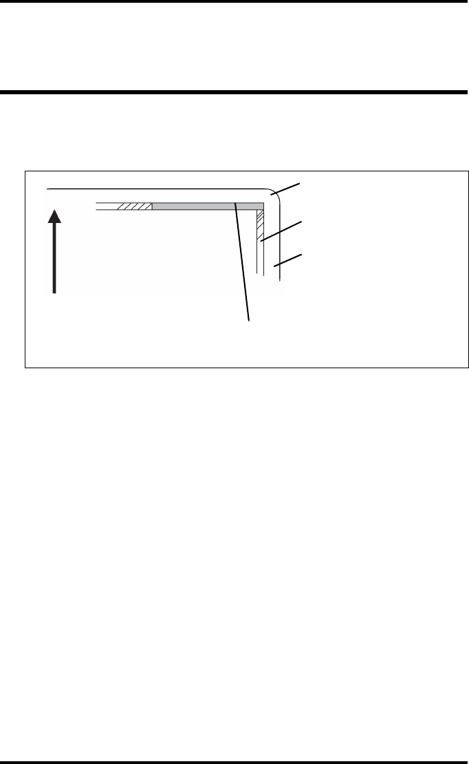
148 2852 A EN 20070205
DRYSTAR AXYS
Viewing the system info area on a
film
On the top right corner of each film, a “System info” area will be printed.
This info can only be read using a magnifying glass.
The System info area contains info about:
QPrinter: (serial number, densitometer info, film counts, software version, etc.),
QController (image source, date, time, etc.).
For more detailed information, refer to the Drystar AXYS Service documenta-
tion.
Film
Diagnostic area
Clear border
Black border
System info area
Transport direction

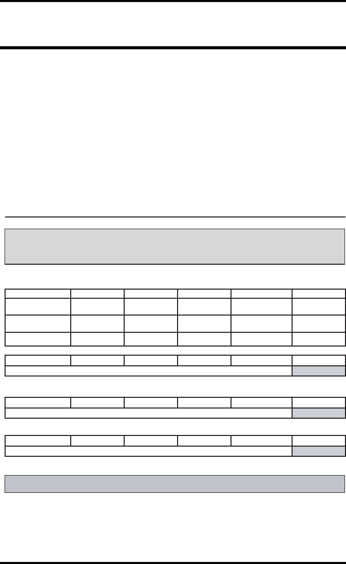
150 2852 A EN 20070205
DRYSTAR AXYS
Charts for general radiography QC
Drystar AXYS : Determination of Operating Levels
Imager Type: __________ Serial #: _________________ Date ____________________
Input Tray ________________Film Type: ____________ Emulsion #: ______________
Densitometer: _________________ (default selection)
Day 1 Day 2 Day 3 Day 4 Day 5
Month
Day
Initials
Low Density
Average of 5 Values = calculated reference “Low Density” level
Mid Density
Average of 5 Values = calculated reference “Mid Density” level
High Density
Average of 5 Values = calculated reference “High Density” level
Step 1: Print QC Test images on five consecutive days. Record the optical densities
measurements in the tables below. After five days, average the values to determine
the operating (aim) levels for each of the parameters.
Step 2: Copy the calculated reference levels to Charts 2A/B ('Daily Density Control Chart')
General radiography applications
Quality Control for Chart 1
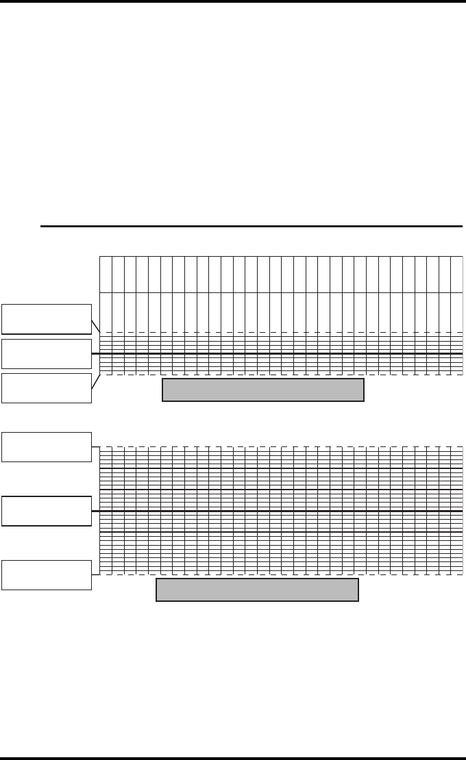
151
2852 A EN 20070205
DRYSTAR AXYS
Drystar AXYS Daily Density
Control Chart
Imager Type: __________ Serial #: _____________ Film Type:____________ Emul #:___________
_
Input Tray:_________
Densitometer: ____________________ (default selection)
Date :
Initia ls:
Low Density
Mid Density
Upper Control limit =
+0.05
Calculated Reference
Low Density Level
Lower Control Limit =
-0.05
Upper Control limit =
+0.15
Calculated Reference
Mid Density Level
Lower Control Limit =
-0.15
General radiography applications
Quality Control for Chart 2A
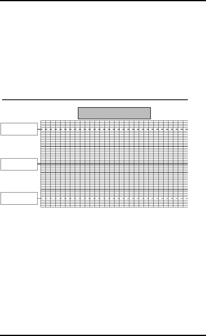
152 2852 A EN 20070205
DRYSTAR AXYS
Drystar AXYS Daily Density
Control Chart
Imager Type: __________ Serial #: _____________ Film Type:____________ Emul #:___________
_
Input Tray:_________
Densitometer: ____________________ (default selection)
High Density
Upper Control limit =
+0.20
Lower Control Limit =
-0.20
Calculated Reference
High Density Level
General radiography applications
Quality Control for Chart 2B
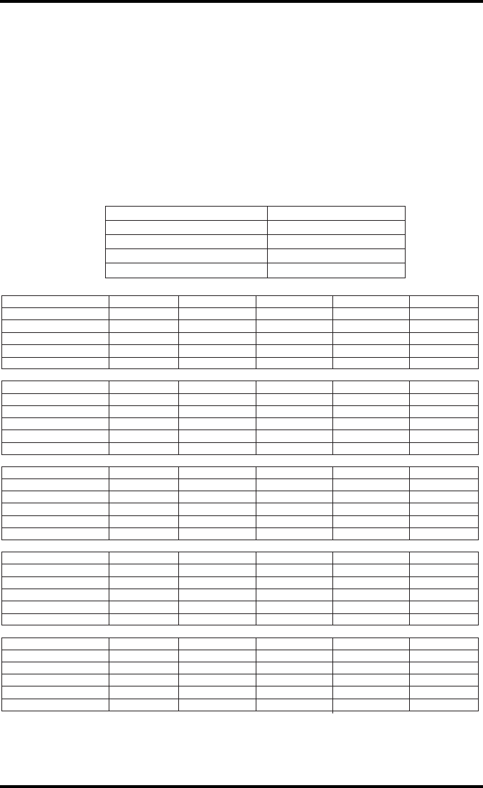
153
2852 A EN 20070205
DRYSTAR AXYS
Drystar AXYS Artifacts and Spatial Resolution
Control Chart
Test Frequency: Weekly Drystar AXYS Serial # _____________
Input Tray: ____________
Initial Reference Test Date
Initial Reference Artifacts
Initial Reference Dot Visibility
Initial Reference Low Contrast
Month
Day
Artifacts
Visibility of all Dots
Month
Day
Artifacts
Visibility of all Dots
Month
Day
Artifacts
Visibility of all Dots
Month
Day
Artifacts
Visibility of all Dots
Month
Day
Artifacts
Visibility of all Dots
Low Contrast Visibility
Low Contrast Visibility
Low Contrast Visibility
Low Contrast Visibility
Low Contrast Visibility
General radiography applications
Quality Control for Chart 3
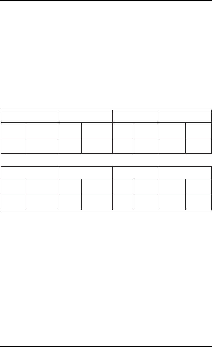
154 2852 A EN 20070205
DRYSTAR AXYS
Drystar AXYS Geometric Consistency
Control Chart
Input Tray: _______________________
Test Frequency: Annually or as required Drystar AXYS Serial # ____________
_
Reference Dimensions
Date: Measured Dimensions
Date: Consistency Aspect Ratio
Aref A: A/Aref A/B
Bref B: B/Bref
Reference Dimensions
Date: Measured Dimensions
Date: Consistency Aspect Ratio
Aref A: A/Aref A/B
Bref B: B/Bref
General radiography applications
Quality Control for Chart 4
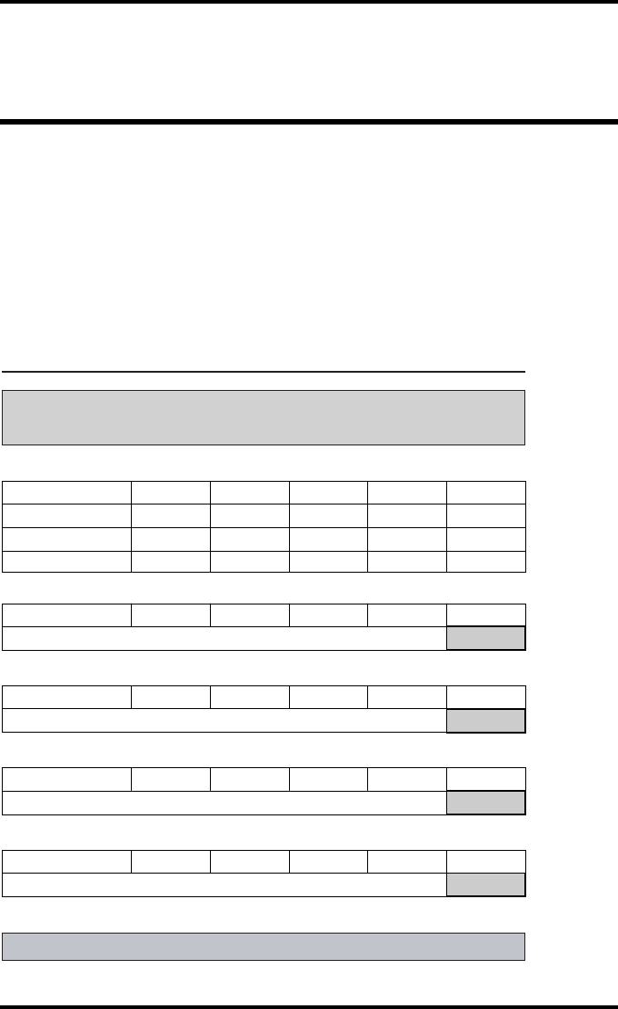
155
2852 A EN 20070205
DRYSTAR AXYS
Charts for mammography QC
(optional)
Drystar AXYS : Determination of Operating Levels
Imager Type: __________ Serial #: _________________ Date ____________________
Film Type: ____________ Emulsion #: ______________
Densitometer
: _________________ (default selection)
Step 1: Print QC Test images on five consecutive days. Record the optical densities
measurements in the tables below. After five days, average the values to determine
the reference levels for each of the parameters.
Mammography applications
Month
Day 1 Day 2 Day 3 Day 4 Day 5
Date
Initials
Average of 5 values = calculated reference "Base + Fog" level
Base + Fog
Average of 5 values = calculated reference "Low Density" level
Low Density
Average of 5 values = calculated reference "Mid Density" level
Mid Density
Average of 5 values = calculated reference "High Density" level
High Density
Step 2: Copy the calculated reference levels to Charts 2A/B ('Daily Density Control Chart')
Input Tray: _______________
Quality Control for Chart 1
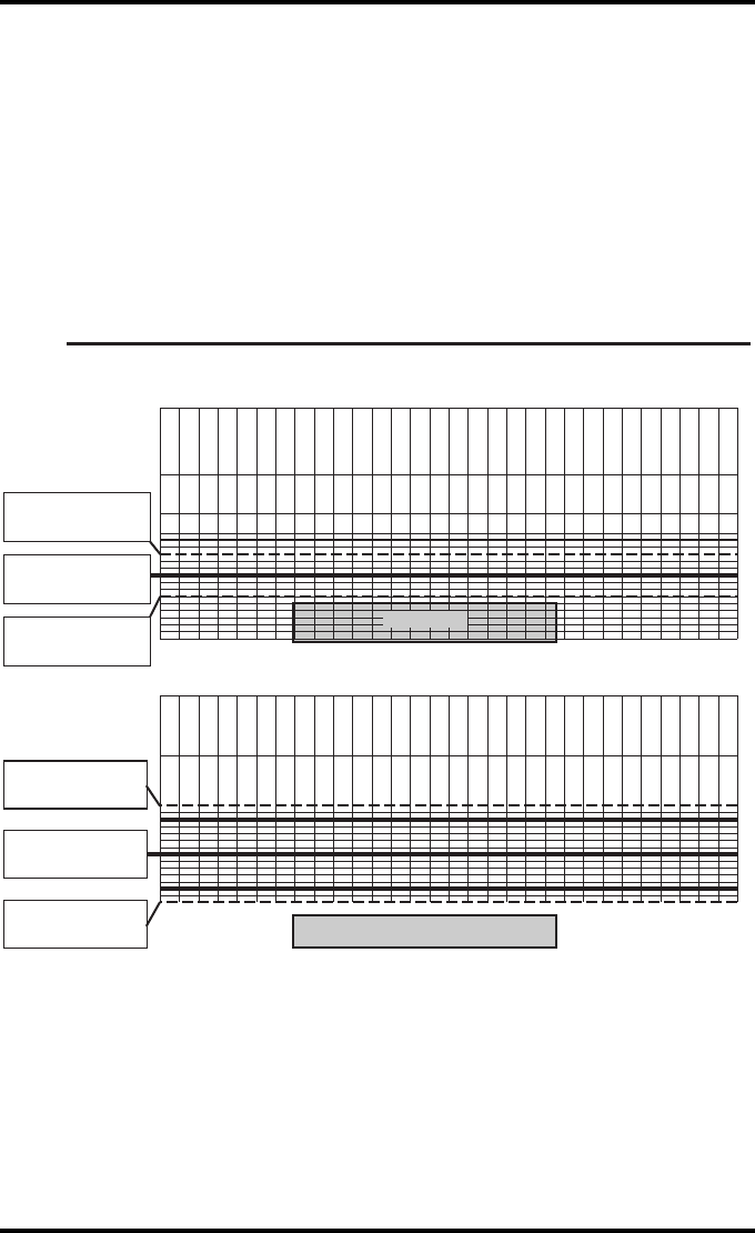
156 2852 A EN 20070205
DRYSTAR AXYS
Drystar AXYS Daily Density
Control Chart
Imager Type: __________ Serial #: _____________ Film Type:____________ Emul #:__________
_
Densitometer: _________________ (default selection)
Mammography applications
Input Tray: ________
Quality Control for Chart 2A
Date:
Initials:
Upper Control limit =
+0.03
Calculated Reference
Base + Fog Level
Base + Fog
Low Density
Lower Control limit =
-0.03
Date:
Initials:
Upper Control limit =
+0.07
Calculated Reference
Low Density Level
Lower Control Limit =
-0.07
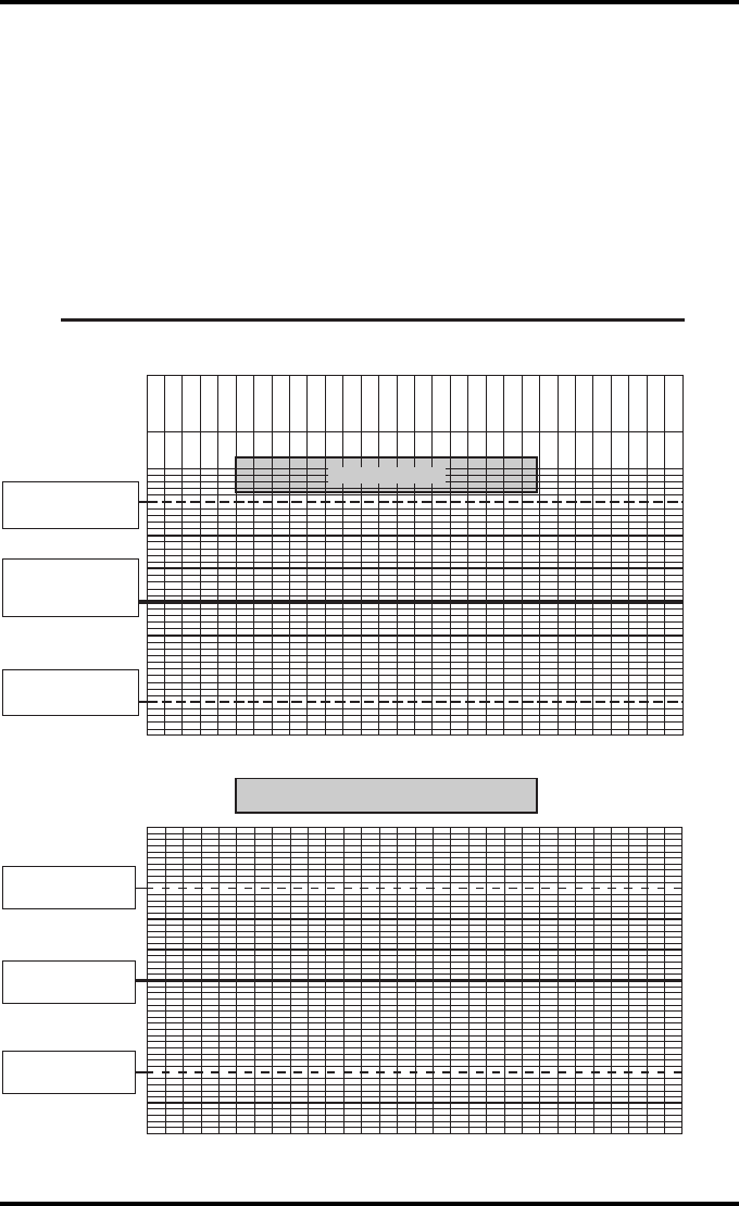
157
2852 A EN 20070205
DRYSTAR AXYS
Drystar AXYS Daily Density
Control Chart
Imager Type: __________ Serial #: _____________ Film Type:____________ Emul #:__________
_
Densitometer: _________________ (default selection)
Mammography applications
Input Tray: ________
Quality Control for
Chart 2B
Date:
Initials:
Upper Control limit =
+0.15
Lower Control limit =
-0.15
Calculated Reference
Mid Density Level
Mid Density
High Density
Upper Control limit =
+0.15
Lower Control Limit =
-0.15
Calculated Reference
High Density Level
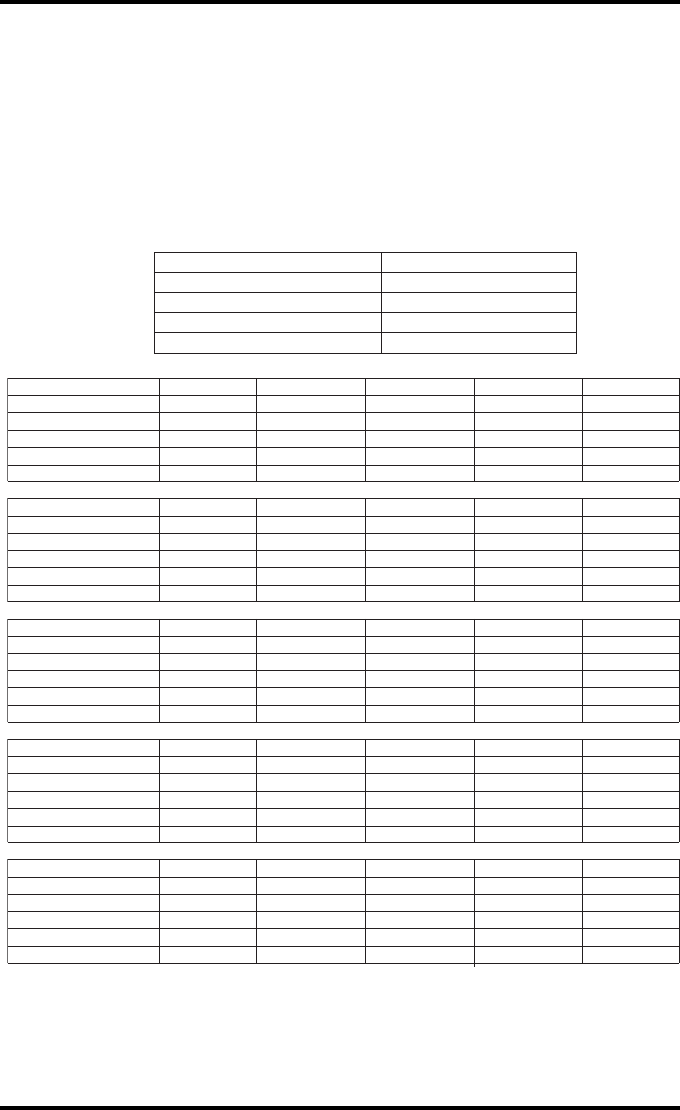
158 2852 A EN 20070205
DRYSTAR AXYS
Drystar AXYS Artifacts and Spatial Resolution
Control Chart
Test Frequency: Weekly Drystar AXYS Serial # _____________
Initial Reference Test Date
Initial Reference Artifacts
Initial Reference Dot Visibility
Initial Reference Low Contrast
Month
Day
Artifacts
Visibility of all Dots
Month
Day
Artifacts
Visibility of all Dots
Month
Day
Artifacts
Visibility of all Dots
Month
Day
Artifacts
Visibility of all Dots
Month
Day
Artifacts
Visibility of all Dots
Low Contrast Visibility
Low Contrast Visibility
Low Contrast Visibility
Low Contrast Visibility
Low Contrast Visibility
Mammography applications
Input Tray: ____________
Quality Control for
Chart 3
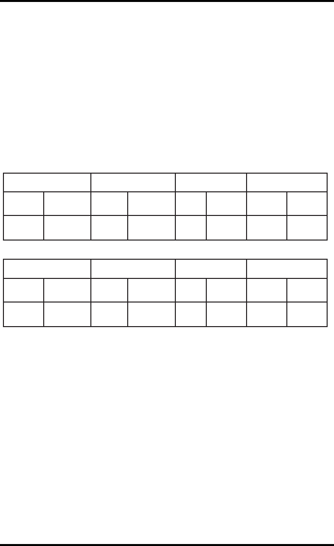
159
2852 A EN 20070205
DRYSTAR AXYS
Drystar AXYS Geometric Consistency
Control Chart
Test Frequency: Annually or as required Drystar AXYS Serial # ____________
Reference Dimensions
Date: Measured Dimensions
Date: Consistency Aspect Ratio
Aref A: A/Aref A/B
Bref B: B/Bref
Reference Dimensions
Date: Measured Dimensions
Date: Consistency Aspect Ratio
Aref A: A/Aref A/B
Bref B: B/Bref
Mammography applications
Input Tray: ______________________
Quality Control for Chart 4

160 2852 A EN 20070205
DRYSTAR AXYS

161
2852 A EN 20070205
DRYSTAR AXYS

Printed in Belgium
Published by Agfa-Gevaert N.V., B-2640 Mortsel-Belgium
2852 A EN 20070205