Agfa NV 5367A Drystar Axys /xxx Medical tabletop printer User Manual manual part 2
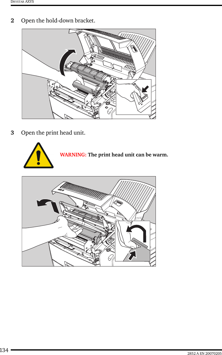
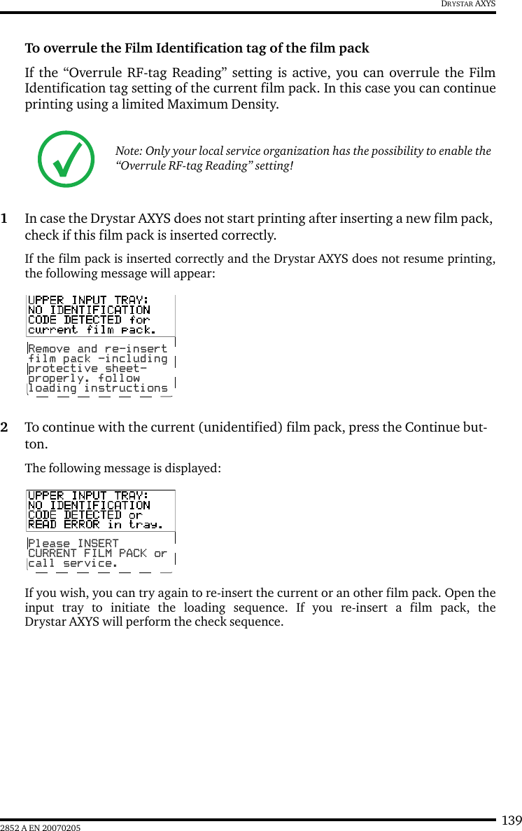
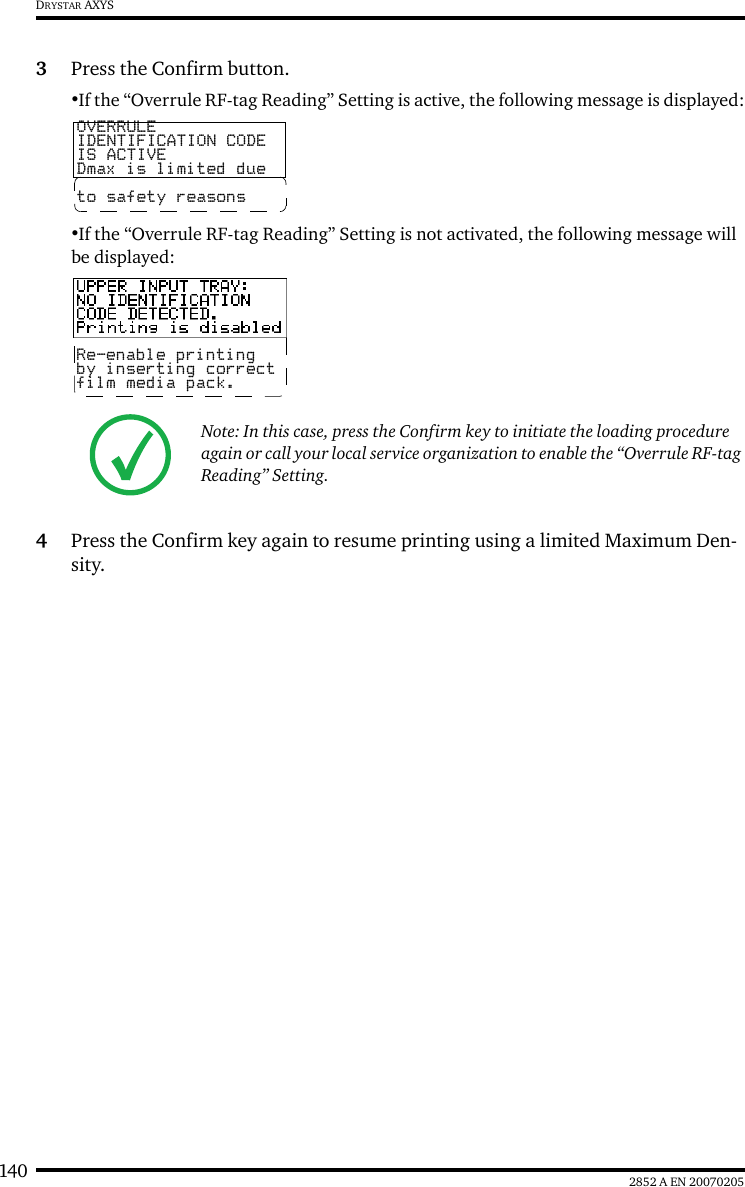
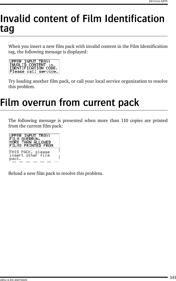
Agfa Gevaert N V Drystar Axys /xxx Medical tabletop printer manual part 2
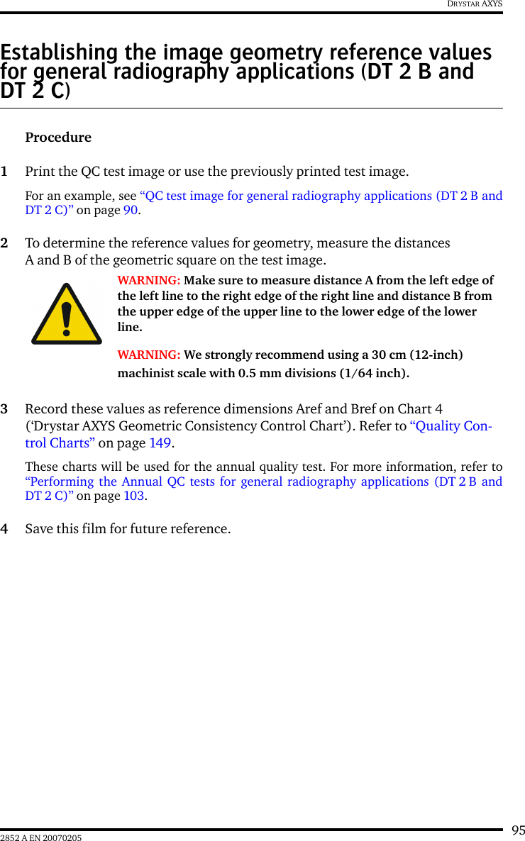
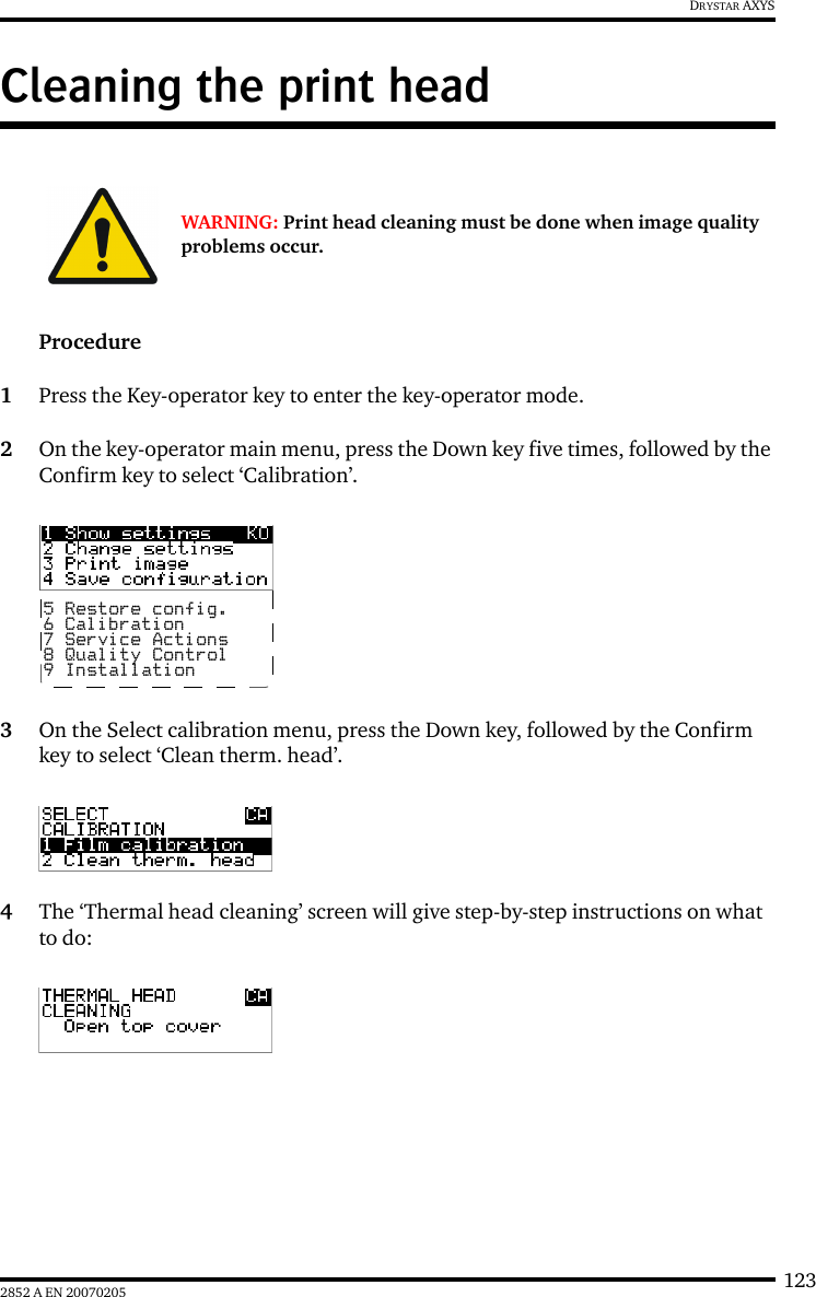
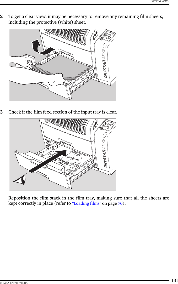
UserManual.wiki
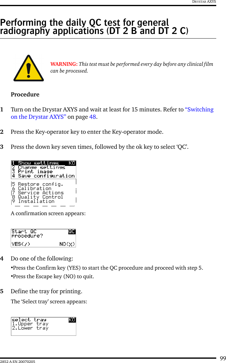
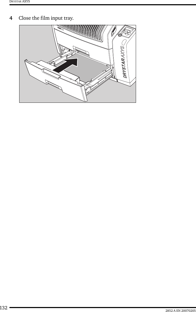
>
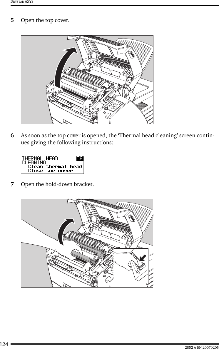
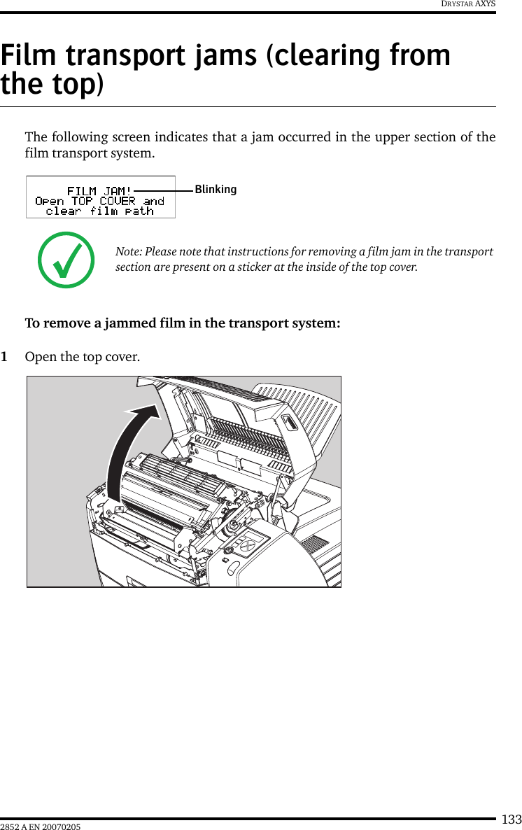
Agfa NV
>
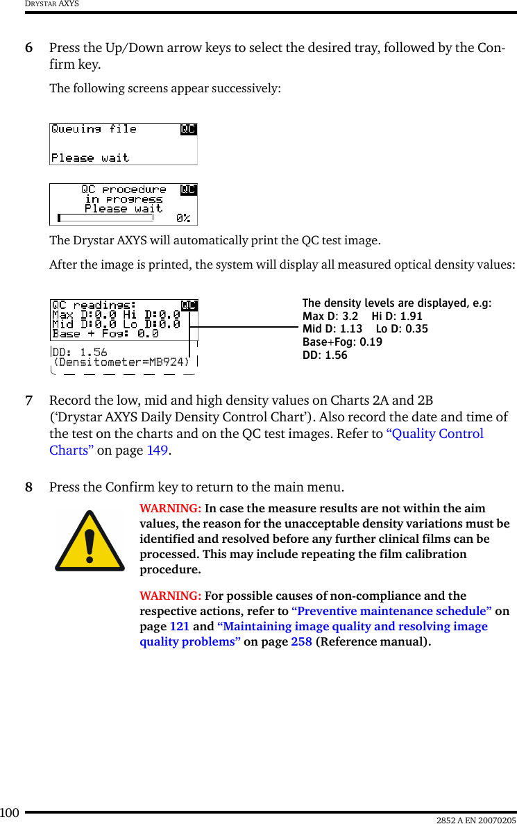
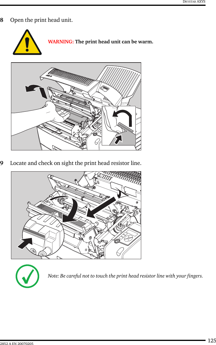
5367A User Manual
>
manual part 2
Contents
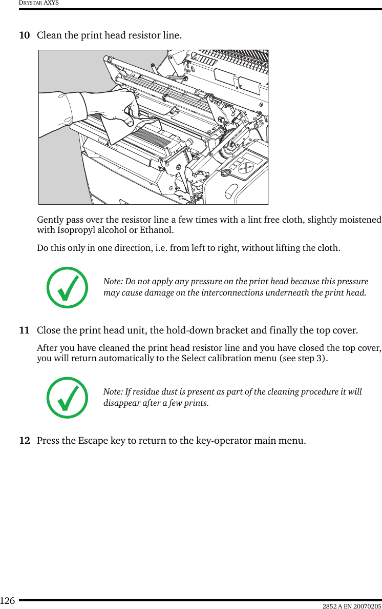
1.
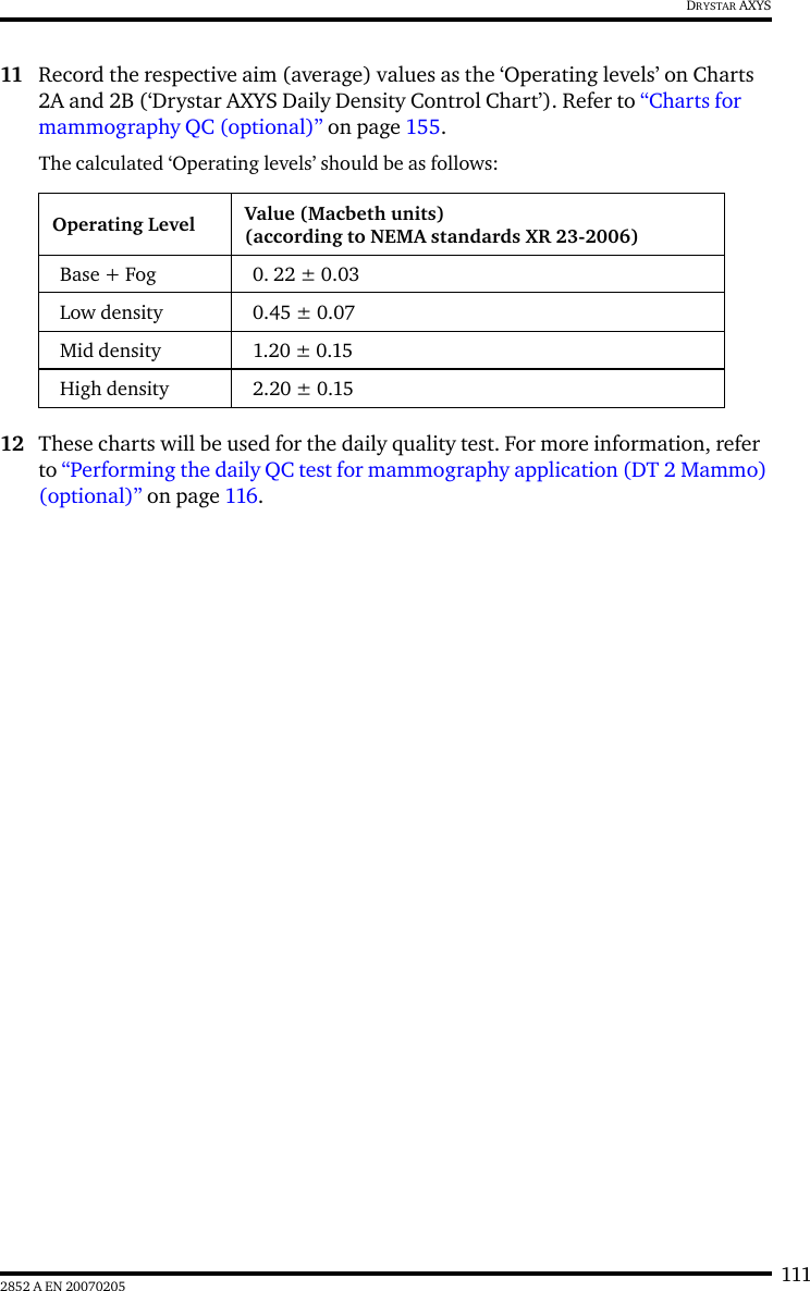
manual part 1
2.
manual part 2
manual part 2
Navigation menu
Upload a User Manual
Namespaces
Wiki Guide
HTML
PDF
Info
Views
User Manual
Discussion / Help
Navigation