Agfa Snapscan 600 Users Manual 300/600 Owner's Guide
600 to the manual a5b1985d-1207-4e67-a171-f67b8bfaffd8
2015-02-05
: Agfa Agfa-Snapscan-600-Users-Manual-505560 agfa-snapscan-600-users-manual-505560 agfa pdf
Open the PDF directly: View PDF ![]() .
.
Page Count: 72
- Preface
- 1 — Preparing the scanner
- 2 — Installing the scanner for the Macintosh computer
- 3 — Installing the scanner for the PC
- Hardware requirements
- Installation of the hardware
- Electronic registration
- Installing the software
- Placing reflective originals
- A — Using the transparency option
- B — Using the automatic document feeder
- C — Troubleshooting
- D — Technical information on the SnapScan 300
- E — Technical information on the SnapScan 600
- F — SnapScan regulation compliance

Abc
The complete picture.
SNAPSCAN
300/600
Owner’s Guide
Preface
This chapter gives you information about SnapScan™, about the
organization, and how to use this online guide .
C h ap t e r 1 — P r e p ari n g t h e s c an n e r
“Preparing the scanner” explains how to prepare your SnapScan for
installation.
Chapter 2 — Installing the scanner for the Macintosh computer
This chapter tells you how to set up your SnapScan for the Apple®
Macintosh®.
Chapter 3 — Installing the scanner for the PC
This chapter shows you how to set up your SnapScan for the PC.
Appendix A — Using the transparency option
This appendix instructs you on how to connect, how to use, and how to clean
the transparency option.
Appendix B — Using the automatic document feeder
Here you find instructions on how to connect, how to use, and how to clean
the automatic document feeder.
Appendix C — Troubleshooting
“Troubleshooting” can be helpful when you come across problems.
Appendix D — Technical information: SnapScan 300
This appendix provides specifications for your SnapScan 300.
Appendix E — Technical information: SnapScan 600
This appendix provides specifications for your SnapScan 600.
Appendix F — Regulation compliance
This appendix gives you information about safety regulations and
electromagnetic interference.

Trademarks 2
Trademarks
AGFA and the Agfa rhombus are registered trademarks of Agfa-Gevaert AG.
FotoLook, FotoSnap and SnapScan are trademarks of Agfa-Gevaert N.V.
Adaptec and EZ-SCSI are trademarks of Adaptec.
Adobe, Acrobat and the Acrobat logo are trademarks of Adobe Systems
Incorporated which may be registered in certain jurisdictions.
Apple, Macintosh and System 7 are trademarks of Apple Computer Inc.,
registered in the U.S. and other countries.
Color It! is a trademark of MicroFrontier, Inc.
IBM PC, AT and XT are trademarks of International Business Machines
Corporation.
Intel is a registered trademark of Intel Corporation
Omnipage Limited Edition is a registered trademark of Caere Corporation.
Windows, Windows NT and the Windows logo are trademarks or registered
trademarks of Microsoft Corporation.
iPhoto Express and iPhotoPlus are trademarks of Ulead.
Other product or company names are trademarks or registered trademarks of their
respective holders.
Copyright © 1997 Agfa-Gevaert N.V.
All rights reserved.
All software and hardware described in this document are subject to change
without any notice.
Conventions
The following conventions are used in this guide:
❖Note: a note of this type gives you additional information.
■Instructions are preceded by a small red square.
1. Numbered steps describe the actions you must take to perform a task.

Contents 3
Contents
Conventions ........................................................................................................................ 2
Preface ............................................................................................... 5
About SnapScan................................................................................................................. 5
Environmental requirements............................................................................................ 6
Precautions.......................................................................................................................... 6
Cleaning your scanner....................................................................................................... 7
SCSI devices ....................................................................................................................... 7
How to use this guide ........................................................................................................ 8
How to print this online guide? ........................................................................................ 9
1 Preparing the scanner ...................................................................... 10
Unpacking the scanner.................................................................................................... 10
Unlocking the scanner..................................................................................................... 11
Locking the scanner......................................................................................................... 12
Taking a closer look.......................................................................................................... 13
Performing a power-on test ............................................................................................ 14
2 Installing the scanner for the Macintosh computer .......................... 15
Hardware requirements.................................................................................................... 15
Installation of the scanner hardware ............................................................................. 16
Choosing a SCSI ID number.................................................................................. 16
Setting the scanner to a SCSI ID number........................................................... 17
Connecting the scanner......................................................................................... 18
Testing the connection.......................................................................................... 22
Electronic registration ..................................................................................................... 22
Installing the software...................................................................................................... 23
Placing reflective originals.............................................................................................. 23
3 Installing the scanner for the PC...................................................... 25
Hardware requirements.................................................................................................... 25
Installation of the hardware............................................................................................. 26
Installation with the Agfa supplied SCSI card .................................................... 26
Installation if your PC already has a SCSI interface card.................................. 31
Testing the connection.......................................................................................... 37
Electronic registration ..................................................................................................... 38
Installing the software...................................................................................................... 38
Windows 95 .............................................................................................................. 38
Windows 3.11........................................................................................................... 40
Windows NT version 3.51 ...................................................................................... 41
Windows NT version 4.0......................................................................................... 42
Placing reflective originals.............................................................................................. 43

Contents 4
Appendix A — Using the transparency option .................................. 44
About your transparency option .................................................................................... 44
Unpacking the transparency option .............................................................................. 44
Unlocking the transparency option ............................................................................... 45
Connecting the transparency option ............................................................................ 45
Placing transparent originals .......................................................................................... 48
Appendix B — Using the automatic document feeder....................... 50
About your automatic document feeder (ADF)............................................................ 50
Unpacking the automatic document feeder................................................................. 51
Taking a closer look.......................................................................................................... 52
Connecting the automatic document feeder............................................................... 53
Operating the automatic document feeder.................................................................. 56
Placing text pages in your automatic document feeder................................... 56
Correcting paper jams............................................................................................. 58
Cleaning the automatic document feeder.................................................................... 60
Cleaning the transparent guide flap .................................................................... 60
Roller cleaning ......................................................................................................... 61
Appendix C — Troubleshooting........................................................ 62
Appendix D — Technical information on the SnapScan 300 ............. 64
SnapScan 300 specifications......................................................................................... 64
Transparency option specifications .............................................................................. 65
Automatic document feeder specifications ................................................................. 66
Appendix E — Technical information on the SnapScan 600 ............. 67
SnapScan 600 specifications......................................................................................... 67
Transparency option specifications .............................................................................. 68
Automatic document feeder specifications ................................................................. 69
Appendix F — SnapScan regulation compliance............................... 70
Safety regulations............................................................................................................ 70
UL Safety Statement............................................................................................... 70
FTZ: Bescheinigung des Herstellers/Importeurs .............................................. 70
TÜV: Wichtige Sicherheitshinweise..................................................................... 71
Electromagnetic interference......................................................................................... 71
Federal Communications Commission Radio Frequency Interference
Statement ................................................................................................................. 71
Canadian department of Communications.......................................................... 72

Preface 5
Preface
About SnapScan
E n v iro n m e n t al r e q u i r e m e n t s
P re c au t io n s
C l e an i n g y o u r s c an n e r
S C S I d e v i c e s
H o w t o u s e t h i s g u i d e
About SnapScan
The SnapScan 300 is a one pass 8-bit flatbed color scanner with a resolution of
300 x 600 ppi equiped with a fluorescent daylight lamp. It is based on CCD
(Charge Coupled Device) scanning technology. With the SnapScan 300, you
can scan line-art, gray-scale and color reflective originals up to A4 format.
The SnapScan 600 is a one pass 10-bit flatbed color scanner with a resolution
of 600 x 1200 ppi equiped with a fluorescent daylight lamp. The scanner works at
10 bit internally. It is based on CCD scanning technology. With the SnapScan
600, you can scan line-art, gray-scale and color reflective originals up to A4
format.
The scanned data is transferred to the computer through SCSI. The computer can
be an Apple Macintosh or PC.
In this Owner’s guide, the name SnapScan is used both for the SnapScan 300
and for the SnapScan 600.
SnapScan is a scanner that captures and converts reflective originals (e.g.
pictures, text) into electronic data that can be used in computer applications. It
offers high-resolution image capturing and is an ideal tool in making
presentations come to life.
If you purchased the automatic document feeder you can scan up to 60 sheets of
text fast and without interruption. Some software packages allow you to convert
the scanned sheets of text into most of the commercially used text file formats.
If you purchased the transparency option , you can scan transparent originals
(e.g. slides) as well.
SnapScan supports multiple scanning modes and includes scanner software to
get you started right away. With its powerful and easy-to-use scanner driver
software, SnapScan gives you easy access to high-quality color scans. The
scanner driver software gives you a number of additional features to create
special effects or to reproduce even the most difficult originals.
The document cover is adjustable: when you put a thicker original (like a book or
a magazine) on the reflective glass plate, the document cover adapts itself to its
thickness.

Preface 6
Environmental requirements
■Place the scanner on a horizontal, flat surface.
■To ensure proper ventilation, allow a minimum of 10 cm (4 inches) free space
around each side of the scanner.
■Make sure that no vibrations or shocks occur.
■Make sure that the area is free of dust.
■Avoid any contact with water.
■Your SnapScan is designed to perform at best when the environmental
temperature is between 10 °C and 40 °C. Avoid exposure to direct sunlight
and heating devices.
■Your SnapScan is designed to perform at best when the environmental
humidity is between 20% and 85%. Avoid environments where humidity
fluctuations might occur.
■Check whether the voltage of the power cord corresponds to the voltage in
your area. If it does not correspond, contact your dealer. Avoid environments
where voltage fluctuations might occur.
Precautions
For your own safety and that of your equipment, respect conscientiously the
environmental requirements and always take the following precautions:
Caution: For the reason of safety, besides the personal maintenance mentioned in this
Owner's Guide, don't try to remove any mechanical parts or any electronic devices. If
you need service, our dealer and service offices are available to help you.
■Handle your SnapScan and its options with care: the glass plates are fragile.
There is no warranty on breaking the glass plates and your dealer is not liable
for consequential damages.
■Check frequently whether there is no overheating of the power plug and
whether the power plug is pushed all the way into the socket.
■Switch off the machine at the end of your working day or during power failure.
■Disconnect the power plug when you want to clean the scanner housing or
the glass plate and when the scanner needs servicing or repairing.
■Do not open the scanner housing as it contains high voltage areas and
sensitive components. Every repair should be carried out by your dealer.
■Do not leave originals on the reflective glass plate for excessive periods of
time. The warmth of the scanner may cause them to deteriorate.
■To avoid crashes, never use extension cables for SCSI cables.
■For safety reasons, never use extension cables for power cords.
Preface 7
Cleaning your scanner
■Cleaning the glass plate regularly, will ensure that dirt or smudges do not
reduce the quality of your scanned images.
■Before cleaning, turn off the power of the scanner and disconnect the power
cord.
■Use a damp cloth and a mild detergent to clean the surface of the glass plate .
If you use alcohol to clean the glass plate, make sure you do not touch the
plastic elements of the scanner.
■Avoid using sprays directly onto the glass plate as this may cause the liquid
to penetrate the seams around the glass and contaminate the mirrors and
lenses inside the scanner.
■Do not use liquid cleaners or aerosol cleaners.
SCSI devices
SnapScan is a Small Computer System Interface (SCSI) device. It communicates
with your computer via the SCSI cable and SCSI card of your computer. The SCSI
communication allows you to have up to seven devices connected to your
computer. Examples of SCSI devices are a SCSI Hard Disk, a SCSI CD-ROM drive,
...
A unique SCSI identity (SCSI ID) number is assigned to each device in the SCSI
chain. So the computer can identify the device it wants to communicate with.
A SCSI chain requires an electronic component called a terminator.
A terminator absorbs old signals traveling along the cables and keeps the path
open for new signals. The chain should never have more than two terminators,
one at each end.
It is important to remember that using too many or too few terminators may
damage your SCSI devices. Some SCSI devices have built-in terminators and
must therefore be placed at the end of your SCSI chain.
❖Note: Your SnapScan does not have a built-in terminator.
Caution: If two SCSI devices have the same ID number, your system will not work
properly and you may damage your SCSI devices. For more information see Choosing a
S CS I I D n umb e r .
Preface 8
How to use this guide
Click any text or graphic that is
identified as hypertext link.
The pointer changes into a pointing
finger when positioned over a link.
Underlined text is “linked” to another
part of this guide.
Click Go Back to return to the previous
page view.
Click on the bookmark name to go to
the topic marked by that bookmark.
Click the triangle to the left of a
bookmark to show and hide
subordinate bookmarks.
Use the First Page or Last Page
button to move the document to the
first or last page of this manual.
Use the Go Back and Go Forward
buttons to retrace your steps in this
guide, moving to each view in the order
visited.
Use the Previous Page or Next
Page button to move the document
backward or forward, one page at a
time.
You can also use the keyboard arrows.
Use the zoom tools to magnify and
reduce the page display.
Click the Find button to search for part
of a word, a complete word, or multiple
words in this document. You can also
consult the supplied index.
Click the Help button to display the
Acrobat Reader Help.
Print Choose Print from the File menu to
print this online guide.

Preface 9
How to print this online guide?
1. Choose Page Setup from the File menu.
2. Choose A4 from the Paper pop-up menu.
3. Select Orientation: Portrait.
4. Click OK.
5. Choose Print from the File menu.

Chapter 1 — Preparing the scanner 10
Chapter 1 — Preparing the scanner
This chapter helps you to prepare your SnapScan for installation.
Unpacking the scanner
U n l o c k i n g t h e s c an n e r
L o c k in g t h e s c an n e r
T ak in g a c lo s e r l o o k
P e rf o rm i n g a p o we r- o n t e s t
Unpacking the scanner
1. Open the packing box and carefully take out all the items.
2. Check each item to make sure that you have everything listed on the box and
the packing list. Check if there is no visible defect.
If something is missing, contact your dealer.
3. Remove the plastic wrapping and the packing materials from the scanner.
❖Note: Save the packing materials to protect the scanner during later
transport.
Chapter 1 — Preparing the scanner 11
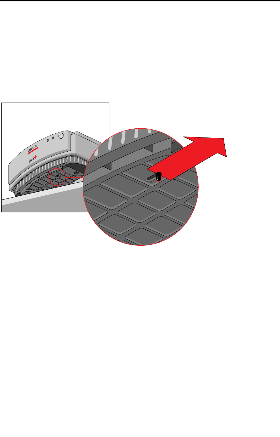
Unlocking the scanner
The scanner’s optical box contains all optical components and rides back and
forth during the scan. A locking slider holds it in place during shipment. You have
to unlock the scanner before you switch on the scanner.
1. Place the scanner on a horizontal, flat surface and pull it forwards until you
can see the locking slider at the base.
2. Slide the locking slider to the right.
Your scanner is unlocked.
3. Move the scanner back on your desktop. Allow a minimum of 10 cm
(4 inches) free space around each side of the scanner .

Chapter 1 — Preparing the scanner 12
Locking the scanner
If you have to move the scanner over long distances, you should first lock the
scanner. This will protect the scanner’s optical carriage from possible damage.
1. Place the scanner on a horizontal, flat surface and pull it forwards until you
can see the locking slider on the underside.
2. Turn on your scanner.
The scanner’s optical assembly moves to its home position.
3. When the status indicator (the left green one) stops blinking, push the
locking slider to the left.
Your scanner is locked.
4. Switch off your scanner.
Chapter 1 — Preparing the scanner 13
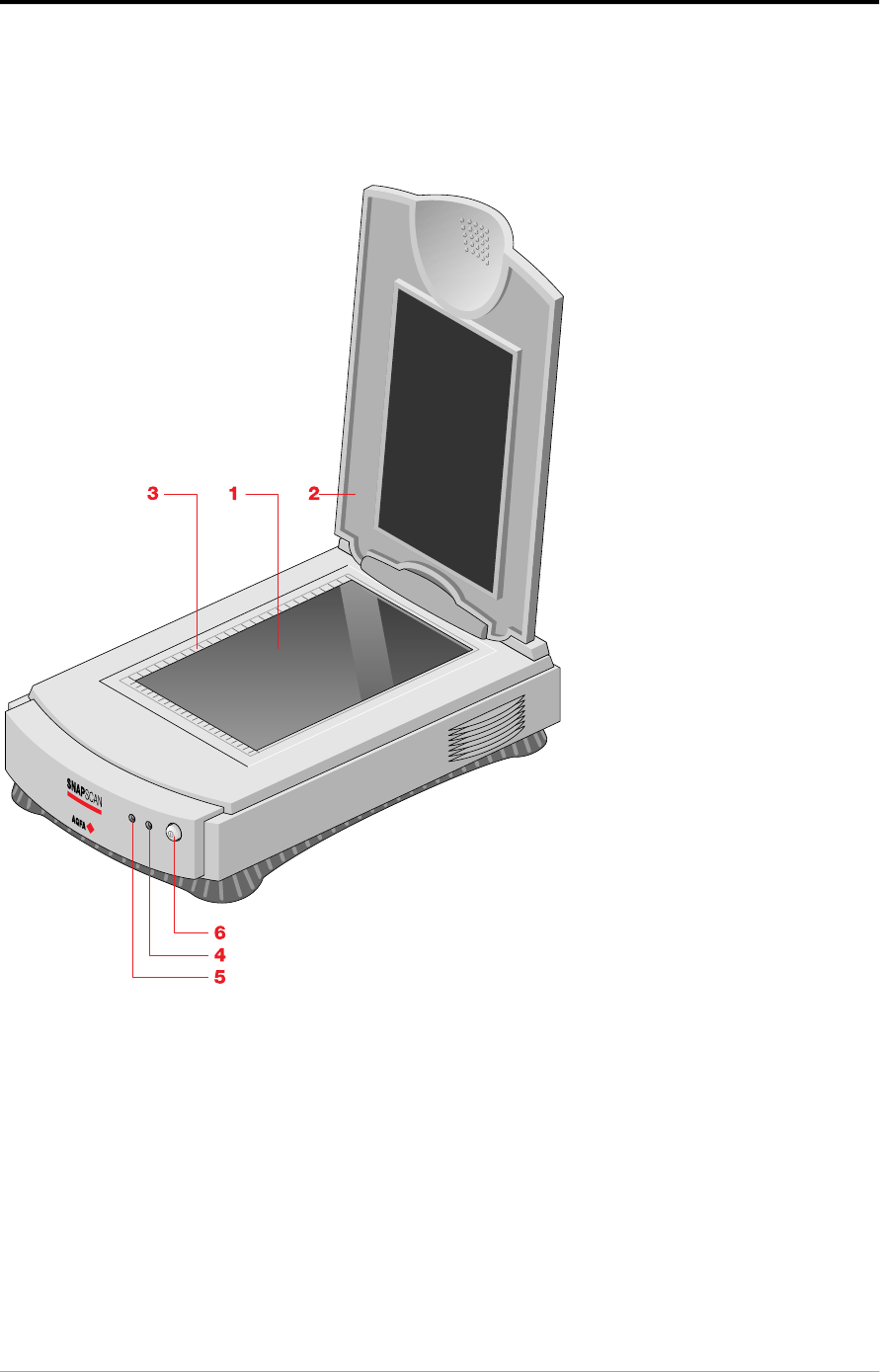
Taking a closer look
Now that you have the scanner out of the box, take a closer look so that you
become familiar with its parts. The figures illustrate the locations of the different
parts of your SnapScan.
1. glass plate
2. adjustable document cover
3. rulers
4. power indicator (the right green one)
5. status indicator (the left green one)
6. power switch
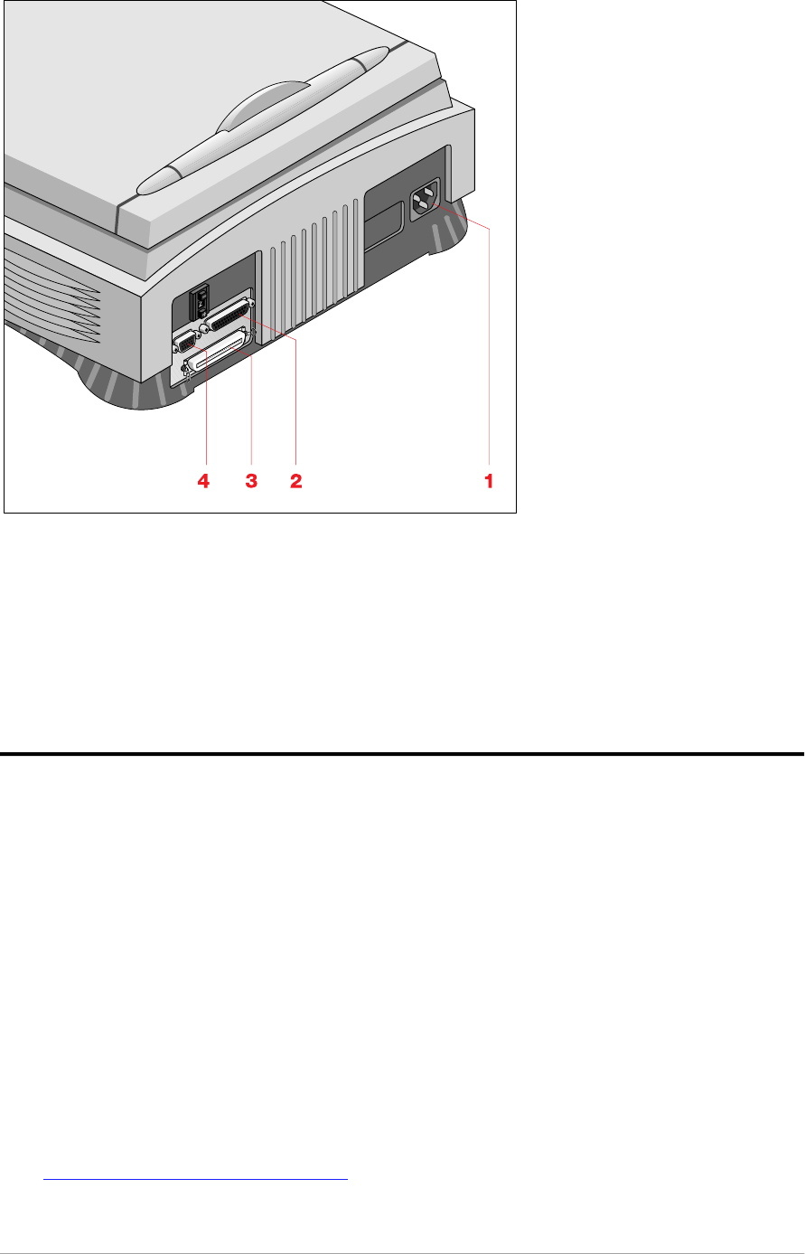
Chapter 1 — Preparing the scanner 14
1. power connector
2. 25-pin SCSI interface connector
3. 50-pin SCSI interface connector
4. female 15-pin connector (for connecting the transparency option or the
automatic document feeder)
Performing a power-on test
You are now ready to perform a power-on test to check if the scanner is operating
correctly.
1. Check whether you have unlocked the scanner.
2. Connect the power cord to the scanner.
Make sure that you are using the correct power cord for the voltage in your
area. If it does not correspond, call your dealer.
3. Switch on the scanner.
The scanner performs a self-test during which the status indicator blinks
slowly. This takes about 15 seconds or less. After the self-test the status
indicator remains on.
If a malfunction is detected during the self-test, that is, if the status indicator
starts blinking at a higher frequency, refer to
Appendix C, “Troubleshooting” .

Chapter 2 — Installing the scanner for the Macintosh computer 15
Chapter 2 — Installing the scanner for the
Macintosh computer
This chapter shows you how to set up your SnapScan with your Macintosh
computer.
Hardware requirements
In s t al l at i o n o f t h e s c an n e r h ard war e
C h o o s in g a S CS I ID n u m b e r
C o n n e c t i n g t h e s c an n e r
T e s t i n g t h e c o n n e c t i o n
E l e c t ro n i c re g i s t rat i o n
In s t al l at i o n o f t h e s o f t w are
P l ac in g r e f l e c t iv e o ri g i n al s
Hardware requirements
■A 68020 processor.
■A 14 inch color monitor with thousands of colors for an accurate display of
color images.
■12 MB of RAM (16 MB is recommended)
■A high-capacity disk drive.
■A CD-ROM drive.
■System 7.1™ or higher.
■The amount of disk space available on your computer determines the number
and the size of the images you can scan. Make sure you have enough free
storage space on your hard disk. You need about two times the size of the
image to scan, edit and save it. You need minimum 20 MB free hard disk
space.
Chapter 2 — Installing the scanner for the Macintosh computer 16
Installation of the scanner hardware
This section shows you how to set up your SnapScan with your Macintosh
computer. First you choose and set a SCSI ID number, then you connect the
scanner to your computer, and finally you test the connection.
Choosing a SCSI ID number
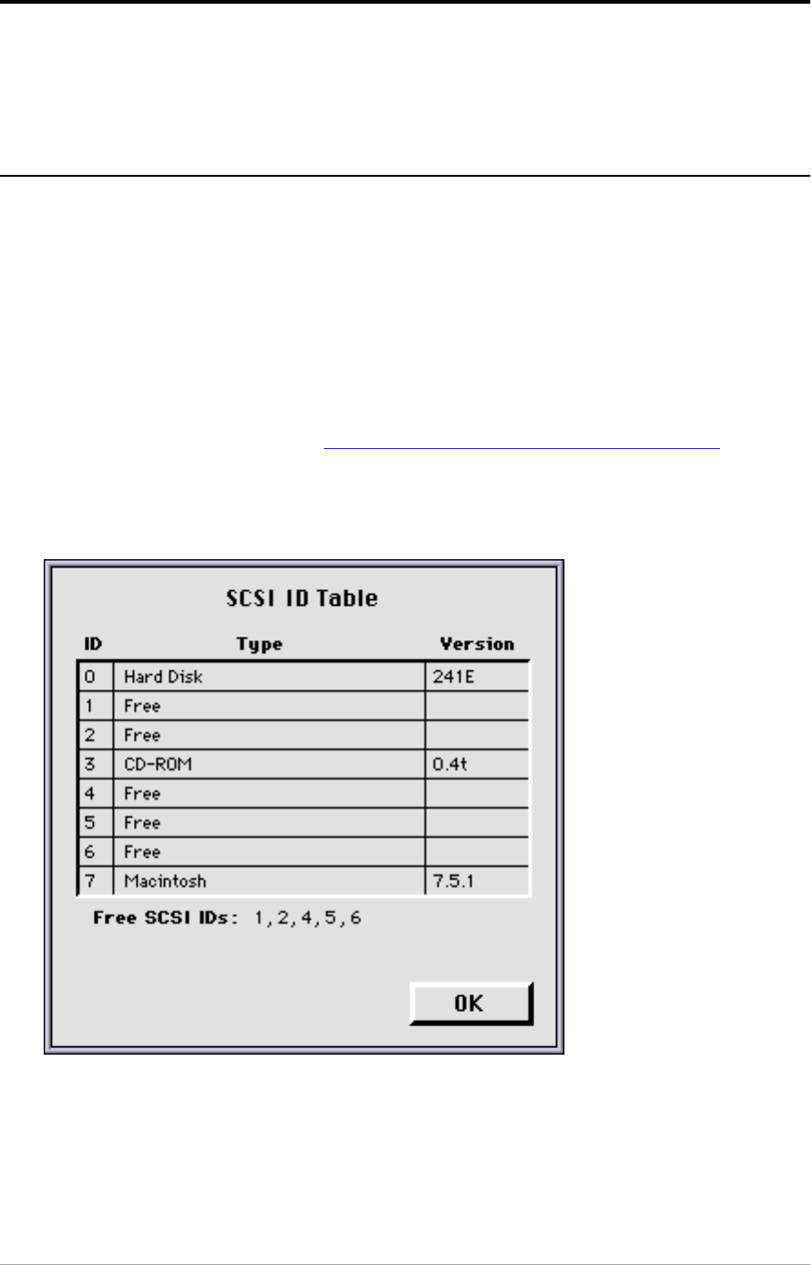
Before you connect your SnapScan to your computer, you have to find out which
SCSI ID numbers are already assigned and which numbers are free. To do this,
you can use the Macintosh utility ‘SCSI ID Checker’. You will find this utility in
the FotoLook™ or FotoSnap™ folder at the top level of your start-up disk after
you installed the software. You will find the instructions for installation of the
software further in this guide.
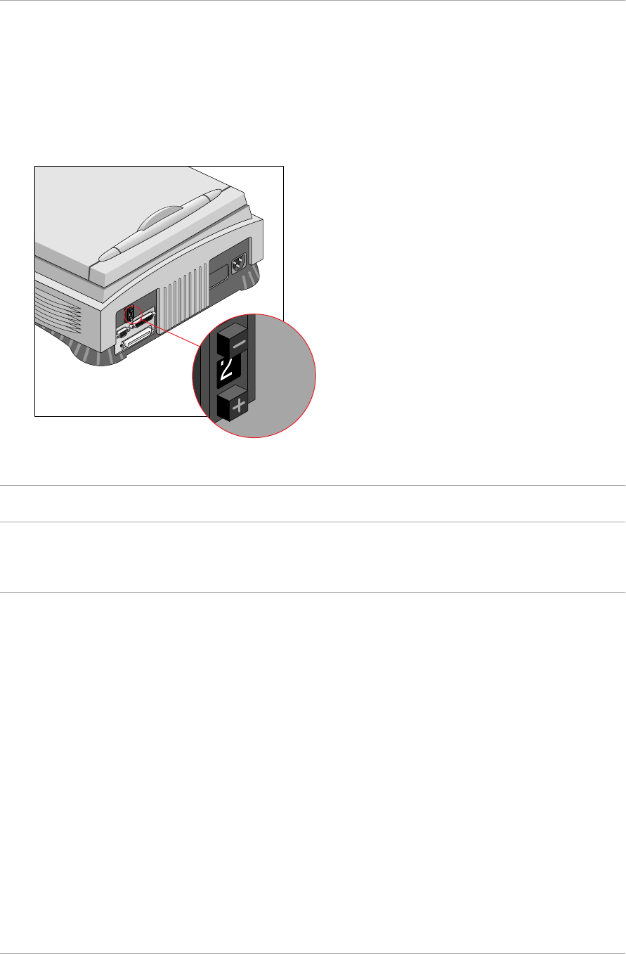
1. Make sure that your scanner is disconnected.
2. Check at the rear of the scanner if the SCSI ID number is set to number 2. If
not, set it to number 2. (see Setting the scanner to a SCSI ID number )
3. Open the SCSI ID Checker.
A dialog box appears with a list of the SCSI ID numbers.
Your Macintosh always occupies ID 7. Its internal hard disk usually occupies
ID 0 or ID 1. The CD ROM usually occupies ID 3. If your Macintosh is equipped
with 2 SCSI-busses, the button Next Bus allows you to switch busses.
Chapter 2 — Installing the scanner for the Macintosh computer 17
4. Check in the SCSI ID table if SCSI ID number 2 is free.
If SCSI ID number 2 is already assigned, you need to set the scanner to a free
SCSI ID number. (see Setting the scanner to a SCSI ID number )
5. Click OK to close the SCSI ID Checker.
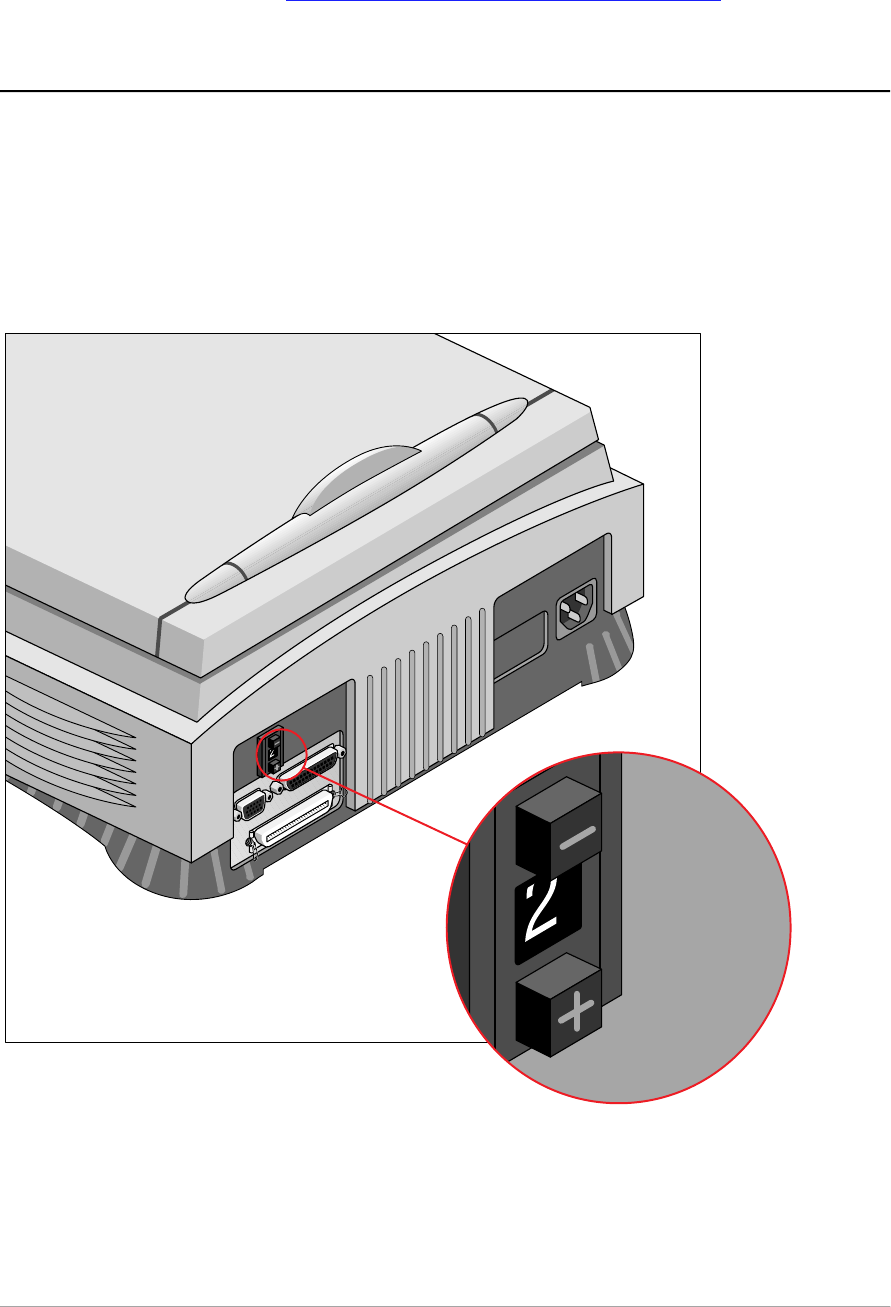
Setting the scanner to a SCSI ID number
1. Make sure your scanner is switched off and is disconnected from your
computer.
2. Choose an unassigned SCSI ID number.
3. Push the button above or underneath the SCSI ID number at the rear of the
scanner until you see the number you want.
Chapter 2 — Installing the scanner for the Macintosh computer 18
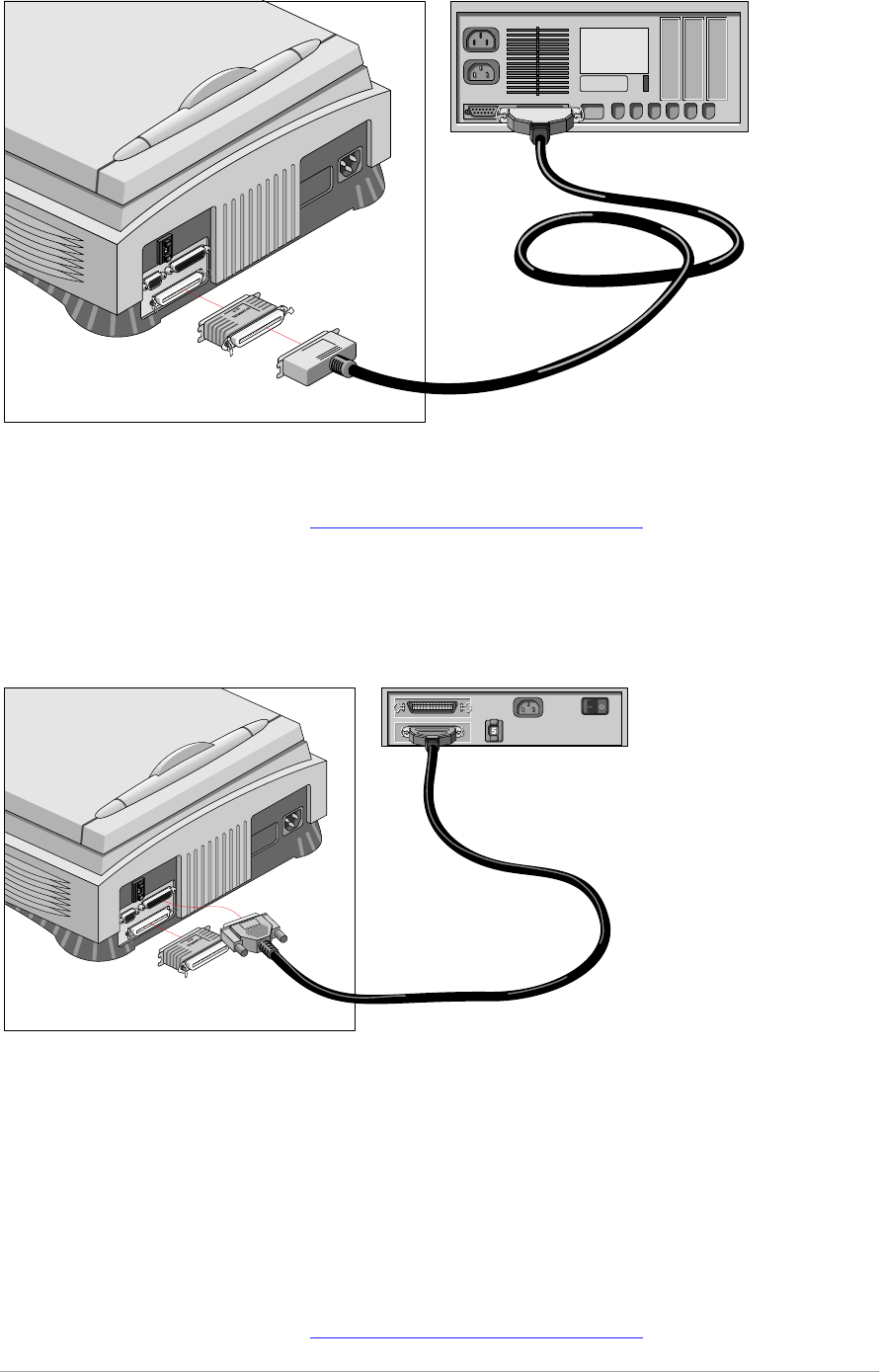
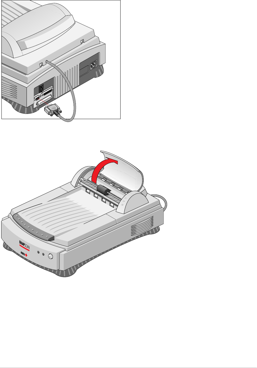
Connecting the scanner
A SCSI cable is supplied with your scanner.
Caution: For safety reasons, never use extension cables for power cords.
Always make sure there is only one terminator in your SCSI chain. You put the device
with the terminator at the end of your SCSI chain. Some SCSI devices, such as the
external hard disk, have built-in terminators and must therefore be placed at the end of
your SCSI chain. Check the documentation of each of your SCSI devices if you are not
sure whether the device has a built-in terminator. The last device of your chain has to be
terminated. Your SnapScan has no built-in terminator. (For more information see
SCSI devices .)
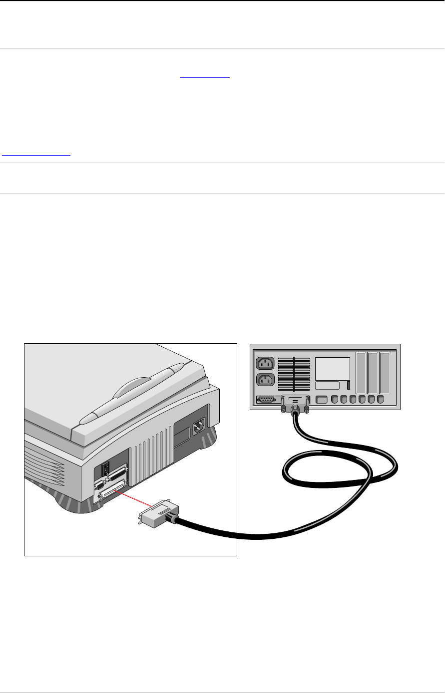
If your SnapScan is the only SCSI device to be connected to your
computer
1. Switch off your scanner and disconnect the power cord.
2. Switch off your computer and disconnect the power cord.
3. Connect the smaller 25-pin end of the SCSI cable to the connector on your
computer.
4. Connect the larger 50-pin end of the SCSI cable to the connector on your
scanner.
Chapter 2 — Installing the scanner for the Macintosh computer 19
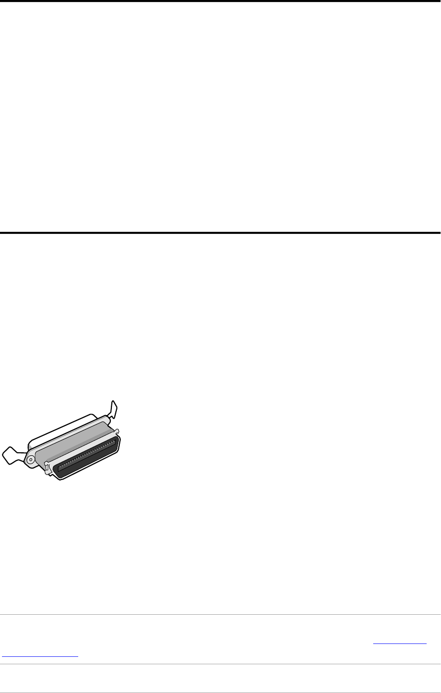
If you use another SCSI cable than the one provided with your scanner, you
have to put a terminator between the connector of your scanner and the SCSI
cable as shown on the picture.
5. Snap the diamond shaped wire clips into the clip brackets to secure the
connection.
❖Note: In case of problems, refer to Appendix C, “Troubleshooting” .
Chapter 2 — Installing the scanner for the Macintosh computer 20
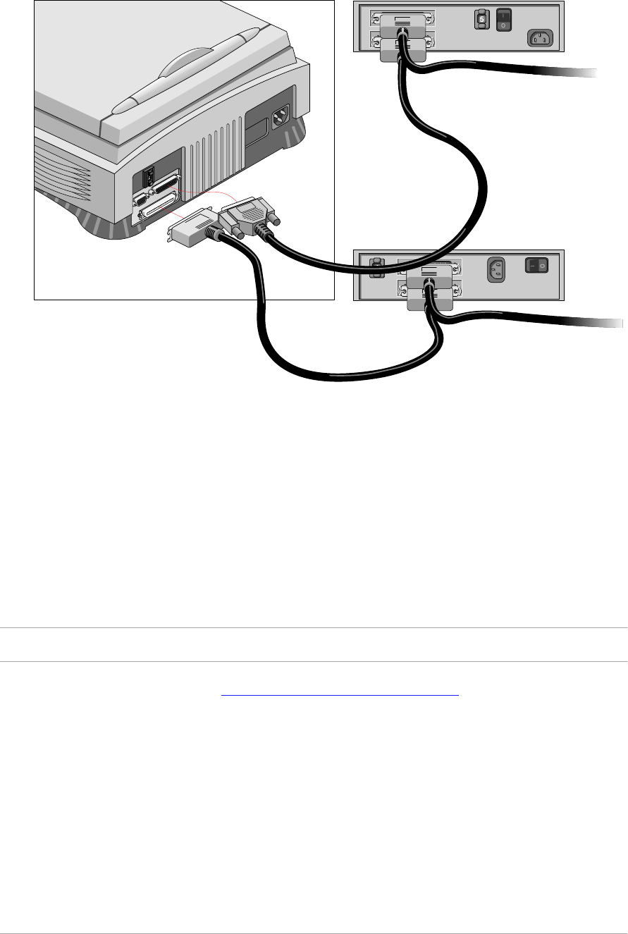
If your SnapScan will be connected to your computer together with
other SCSI devices
■If you install the scanner at the end of your SCSI chain.
1. Remove the terminator from the last device in the SCSI chain.
2. Connect the 50-pin end of the SCSI cable to the connector that has become
available on this device.
3. Place the terminator on the free 50-pin connector of the scanner.
4. Connect the 25-pin end of the SCSI cable to the free connector of the
scanner.
5. Snap the diamond shaped wire clips into the clip brackets to secure the
connection.
❖Note: In case of problems, refer to Appendix C, “Troubleshooting” .
Chapter 2 — Installing the scanner for the Macintosh computer 21
■If you install the scanner between two other devices:
Caution: Do not connect a terminator directly to the scanner in this configuration.
1. Disconnect your SCSI cable from one of these two devices.
2. Connect the free end of this SCSI cable to the scanner.
3. Connect the 50-pin end of the SCSI cable (the one supplied with your
scanner) to the other adjacent SCSI device.
4. Connect the 25-pin end of the SCSI cable (the one supplied with your
scanner) to the scanner.
5. Snap the diamond shaped wire clips into the clip brackets to secure the
connection.
6. Make sure that the last device in the chain is terminated.
❖Note: In case of problems, refer to Appendix C, “Troubleshooting” .

Chapter 2 — Installing the scanner for the Macintosh computer 22
Testing the connection
You are now ready to perform a test to check if the scanner is correctly connected
to your Macintosh computer.
Caution: Make sure the scanner is unlocked.
1. Connect the power cord to the scanner.
Use the correct power cord for the voltage in your area. SnapScan
automatically adjusts to any AC electrical outlet rated from 100V to 240V.
2. Check if the SCSI cable is properly connected.
3. Switch on your scanner.
The scanner performs a self-test during which the status indicator blinks
slowly. This takes about 15 seconds or less. After the self-test the status
indicator remains on.
If a malfunction is detected during the self-test, that is, if the status indicator
starts blinking at a higher frequency, refer to
Appendix C, Troubleshooting .
4. Switch on any other SCSI devices you may have attached, and wait for them
to start up.
5. Switch on your Macintosh.
As your Macintosh computer starts up, it performs a series of tests to verify
the correct system configuration.
6. Open the SCSI ID checker. For more information see
Choosing a SCSI ID number .
7. Verify whether the computer sees the scanner at its proper SCSI ID.
In case of problems, refer to Appendix C, Troubleshooting .
8. Close the SCSI ID checker.
Electronic registration
Use the electronic registration on the Agfa Scanners CD-ROM. You will be asked
to register when you install the software that came with your scanner. You will find
the product serial number at the rear of your scanner.
1. Insert the Agfa scanners CD ROM in your CD ROM drive.
Your computer automatically scans the CD and opens the AGFA scanners
window.
2. Click your language: English.
You will be asked if you want to install Acrobat™. You need Acrobat to read
your documentation.
3. Click SnapScan.

Chapter 2 — Installing the scanner for the Macintosh computer 23
4. Click Install software.
5. Click Register.
6. Follow the instructions on your screen.
Installing the software
1. Disable the virus protection software. You can turn it off in the Extensions
Manager Control Panel or you can drag the software out of the System
Folder.
❖Note: After installing, enable the virus protection software again.
2. Restart your computer.
3. Insert the Agfa Scanners CD-ROM in the CD-ROM drive of your Macintosh
computer.
4. Double-click the installer Icon to start the program.
5. Make your choice in every successive screen.
Install Adobe™ Acrobat Reader (to read the documentation), FotoSnap (the
easy-to-use scanner driver), and FotoLook (the professional scanner driver).
6. Remove the Agfa Scanners CD-ROM.
7. Insert the Software Collection CD-ROM.
8. Double-click the installer Icon to start the program.
9. Make your choice in every successive screen.
Install ColorIt!™ (the image editing software).
For the latest up-to-date information, refer to the Read Me files that will be
installed on your computer.
To install any additional software that came with your scanner, follow the
instructions of the manufacturer.
Placing reflective originals
You can place a reflective (photographic) original directly on the scanner’s glass
plate.
The following steps explain how to position your reflective original on your
scanner.
1. Raise the document cover of the scanner.
Chapter 2 — Installing the scanner for the Macintosh computer 24
If you have acquired and installed a transparency option (Refer to Appendix
A , “ U s i n g t h e t r an s p are n c y o p t i o n ” ) or a automatic document feeder (Refer to
Appendix B, “Using the automatic document feeder” ), you do not have to
remove it for scanning reflective originals: just raise the transparency option
or the automatic document feeder.
2. Place the original face down on the glass plate with the top side against the
middle of the front ruler.
The optical performance of a CCD scanner is always best near the middle of
the glass plate.
If you put more than one original on the glass plate, position them as close to
the center line as possible to optimize quality.
3. Lower the document cover of the scanner.
The adjustable document cover makes it possible to scan from books and
magazines. When you put a thicker original on the reflective glass plate, the
document cover adapts to its thickness.

Chapter 3 — Installing the scanner for the PC 25
Chapter 3 — Installing the scanner for the PC
This chapter shows you how to set up your SnapScan with your PC.
Hardware requirements
In s t al l at i o n o f t e s c an n e r h ard war e
In s t al l at i o n w i t h t h e A g f a s u p p l i e d S C S I c ard
In s t al l at i o n i f y o u r P C al r e ad y h as a S CS I c ar d
T e s t i n g t h e c o n n e c t i o n
E l e c t ro n i c re g i s t rat i o n
In s t al l i n g t h e s o f t w are
P l ac in g r e f l e c t iv e o ri g i n al s
Hardware requirements
■A 486 processor.
■A 14 inch color monitor.
■A 16-bit video card for an accurate display of color images.(minimum 256
colors / High Color (16bit) is recommended)
■12 MB of RAM. (16 MB of RAM is recommended).
■FotoLook and FotoSnap are compatible with all IBM™ PC's and compatibles
capable of running MS Windows 3.1™, Windows 95™, Windows NT™ 3.51 or
4.0 for Intel® platforms.
■An ASPI compatible SCSI card.You can use the SCSI interface card that is
delivered with your SnapScan (See Installing the SCSI interface card ) or you
can use your own SCSI interface card if you have one. In general, FotoLook
supports all fully WINASPI compatible cards. Some SCSI cards require a
special SCSI cable (e.g. wide SCSI). Contact your supplier for the proper
cable.
If you do not use the SCSI interface card that is supplied with your SnapScan,
you should look at your PC's documentation about installing SCSI interface
cards. Check the installation and set-up guidelines in the documentation that
is supplied together with your SCSI interface card.
■A CD-ROM drive.
■The amount of disk space available on your PC determines the number and
the size of the images you can scan. Make sure you have enough free
storage space on your hard disk. You need about two times the size of the
image to scan, edit and save it. You need a minimum of 30 MB free hard disk
space.

Chapter 3 — Installing the scanner for the PC 26
Installation of the hardware
This section shows you how to set up your SnapScan with your PC. You can find
information on the SCSI interface card, instructions for connecting the scanner to
your PC and instructions for testing the connection.
Installation with the Agfa supplied SCSI card
Installing the SCSI interface card
SnapScan requires a SCSI interface card to work with your PC, PC-AT™, 386,
486, or compatible computer.
We assume that you have no other SCSI devices installed and that you use the card and
cable that are supplied by Agfa.
1. Switch off your computer and disconnect the power cord.
2. Remove the cover of your computer.
3. Find a free 16-bit ISA expansion slot.
❖Note: For more information, refer to your computer manual.
4. Remove the corresponding slot cover from the back of the computer chassis.
Keep the screw that held the cover in place.
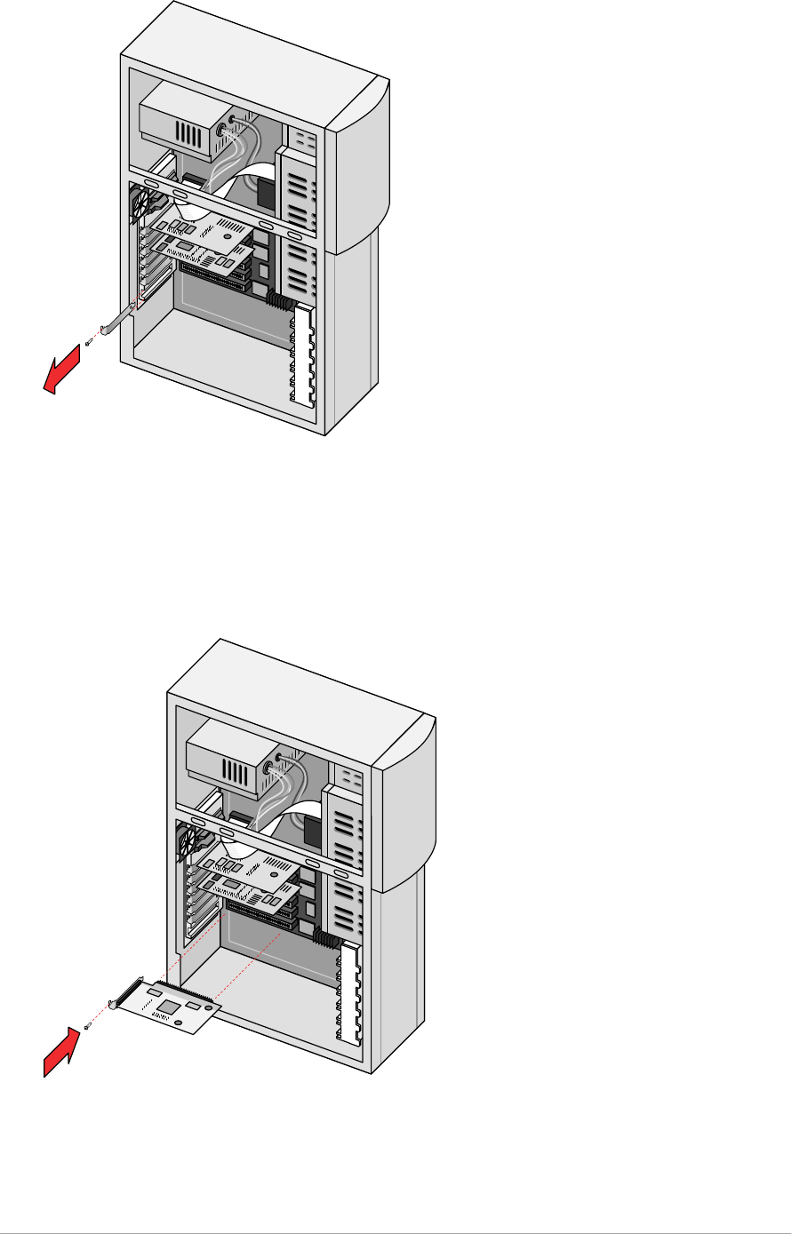
Chapter 3 — Installing the scanner for the PC 27
5. Touch some metal part of the computer and then remove the SCSI card from
its antistatic bag, holding it by its metal support bracket. Static electricity can
damage your card.
6. Position the SCSI card in the expansion slot and press down firmly.
Make sure the card is inserted completely. You can feel it snap into place.
7. Secure the card with the screw that you removed in step 4.
8. Put back the cover of the PC.
Chapter 3 — Installing the scanner for the PC 28
Choosing a SCSI ID number
1. Make sure your scanner is disconnected.
2. Check at the rear of the scanner if the SCSI number it is set to SCSI ID
number 2. If it is not, set it to SCSI ID number 2.
Push the button above or underneath the SCSI number at the rear of your
scanner.
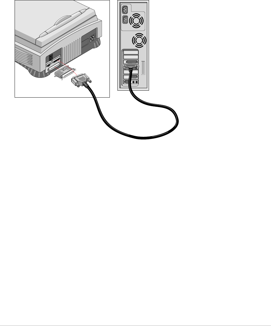
Connecting the Scanner
Caution: For safety reasons, never use extension cables for power cables.
Never try to connect the scanner to the serial or parallel port of your PC: you might
seriously damage your equipment if you do.
1. Switch off your computer and disconnect the power cord.
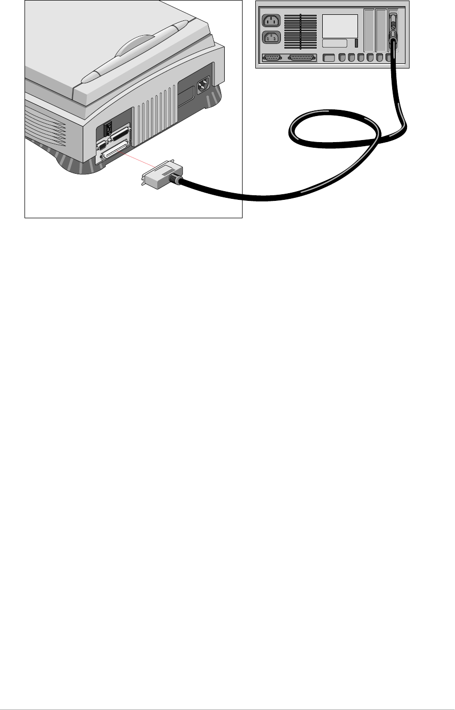
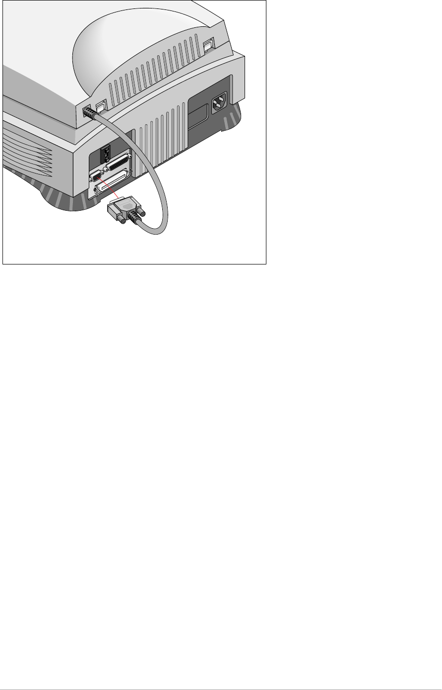
2. Plug the 25 pin connector of the SCSI cable into the SCSI card connector of
your computer.
A SCSI cable is supplied with your scanner.
3. Plug the 50 pin connector of the SCSI cable to the SCSI connector at the rear
of the scanner.
Chapter 3 — Installing the scanner for the PC 29
4. Connect the power cord to the computer.
5. Connect the power cord to the scanner.

Chapter 3 — Installing the scanner for the PC 31
Installation if your PC already has a SCSI interface card
Choosing a SCSI ID number
Before you connect your SnapScan to your PC, you have to find out which SCSI
ID numbers are already assigned and which numbers are free.
1. Make sure that your scanner is disconnected.
2. Check at the rear of the scanner if the SCSI ID number is set to number 2.
■If it is not, set it to number 2 .
If you want to install EZ-SCSI™, the SCSI ID checker software, follow the
instructions.
If you already have software installed to check which SCSI ID numbers are free,
go to step 10.
3. Insert the Agfa Scanners CD-ROM into your CD-ROM drive.
Windows 95 should detect the CD-ROM and then automatically run the
installation program.
If Windows 95 does not run the program, first double-click the CD-ROM icon
in ‘My Computer’ and then double-click agfascan.exe. If you have
Windows 3.11. Open the Program Manager and from the File menu choose
Run. Then type d:\agfascan.exe and press <Enter>. If your CD-ROM
drive is not using the drive letter “d”, replace “d” by the drive letter of your
CD-ROM.
4. Go to the screen “Choose your action”.
5. Choose Install software.
6. Choose Agree and Install.
7. Choose EZ-SCSI.
8. Follow the instructions on the screen.
9. Close the installation program
10. Open the SCSI interrogator.
A dialog box appears with a list of the SCSI ID numbers that are free in your
PC.
Your PC SCSI card mostly occupies ID 7. If your PC is equipped with 2 SCSI-
busses, the Adapter menu allows you to switch busses. Choose the
appropriate bus.
11. Check if SCSI ID 2 is free.
Your SnapScan is preset to ID 2.
■If SCSI ID number 2 is free, close the SCSI interrogator.
■If SCSI ID number 2 is already assigned, you need to set the scanner to a free
S C S I ID n u m b e r .

Chapter 3 — Installing the scanner for the PC 32
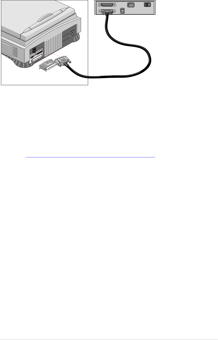
Connecting the scanner
Before you connect the scanner to your PC, make sure that your scanner as well
as your PC are switched off.
A SCSI cable is supplied with your scanner.
❖Note: If the cable does not fit, contact your dealer.
Caution: For safety reasons, never use extension cables for power cables.
Always make sure there are no more than two terminators in your SCSI chain, one at the
beginning and one at the end. Some SCSI devices, such as an external hard disk, have
built-in terminators and must therefore be placed at the end of your SCSI chain. Please
check the documentation of each of your SCSI devices if you are not sure whether the
device has a built-in terminator. The last device in your chain has to be terminated. Your
SnapScan has no built-in terminator. For more information about SCSI devices see
earlier in this chapter: SCSI devices
Never try to connect the scanner to the serial or parallel port of your PC: you might
seriously damage your equipment if you do.
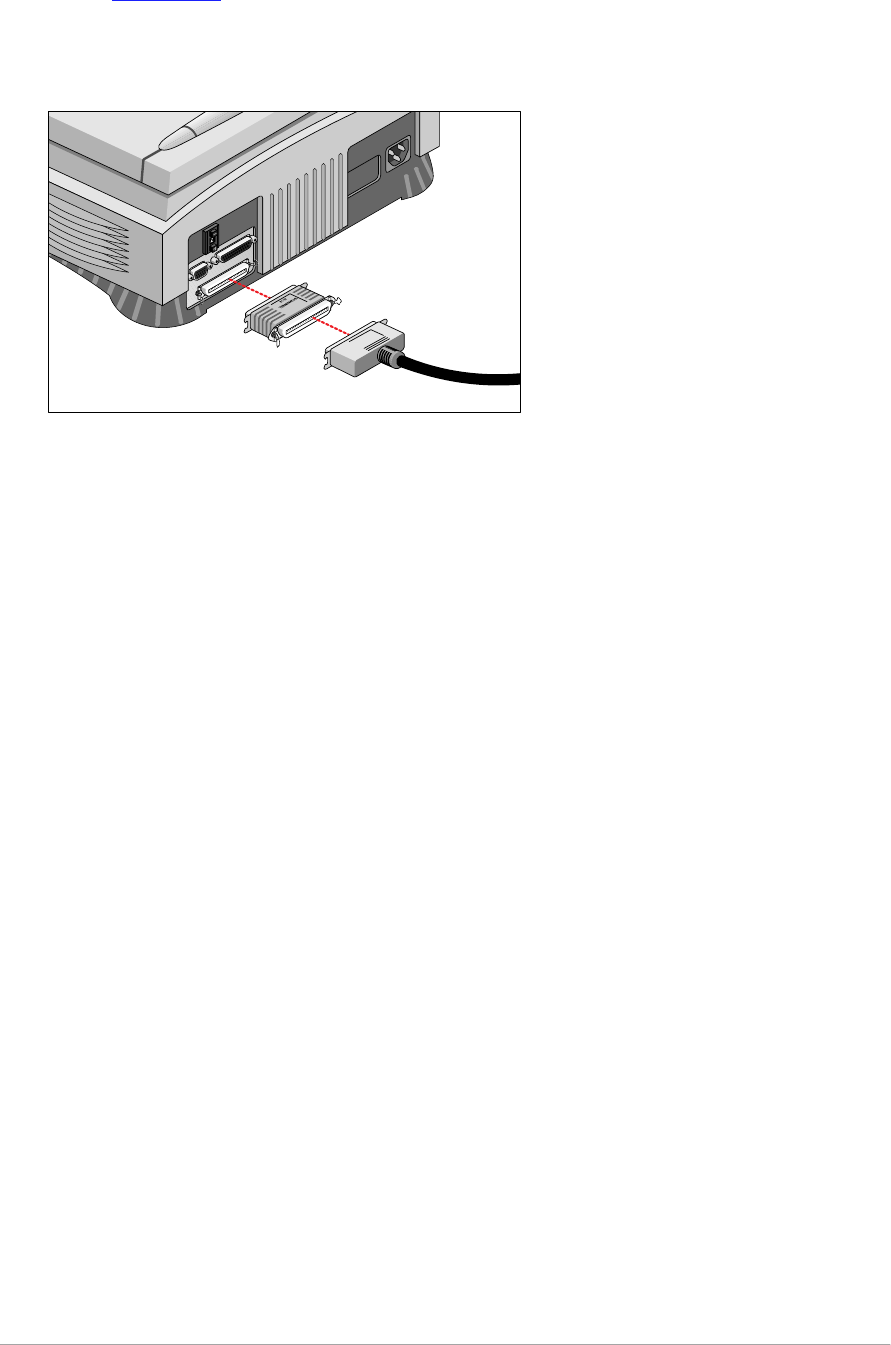
1. Your PC has a 25 pin connector
If your SnapScan is the only SCSI device to be connected to your computer:
1. Switch off your scanner and disconnect the power cord.
2. Switch off your computer and disconnect the power cord.
3. Connect the smaller 25-pin end of the SCSI cable to the connector on your
computer.
4. Connect the larger 50-pin end of the SCSI cable to the connector on your
scanner.
You have to put a terminator between the connector of your scanner and the
SCSI cable as shown on the picture.
Chapter 3 — Installing the scanner for the PC 33
5. Snap the diamond shaped wire clips into the clip brackets to secure the
connection.
In case of problems, refer to Appendix C, “Troubleshooting” .
If your SnapScan will be connected to your computer together with other SCSI
devices:
■If you install the scanner at the end of your SCSI chain:
1. Remove the terminator from the last device in the SCSI chain.
2. Connect the 50-pin end of the SCSI cable to the connector that has become
available on this device.
3. Put the terminator on the free 50-pin connector of the scanner.
4. Connect the 25-pin end of the SCSI cable to the free connector of the
scanner.
5. Snap the diamond shaped wire clips into the clip brackets to secure the
connection.
In case of problems, refer to Appendix C, “Troubleshooting” .
Chapter 3 — Installing the scanner for the PC 34
■If you install the scanner between two other devices:
1. Disconnect your SCSI cable from one of these two devices.
2. Connect the free end of this SCSI cable to the scanner.
3. Connect the 50-pin end of the SCSI cable (the one supplied with your
scanner) to the other adjacent SCSI device.
4. Connect the 25-pin end of the SCSI cable (the one supplied with your
scanner) to the scanner.
5. Snap the diamond shaped wire clips into the clip brackets to secure the
connection.
6. Make sure that the last device in the chain is terminated.
Caution: Do not connect a terminator directly to the scanner in this configuration.
In case of problems, refer to Appendix C, “Troubleshooting” .
Chapter 3 — Installing the scanner for the PC 35
2. Your PC has a 50-pin connector
Your SnapScan is the only SCSI device to be connected to your PC:
1. Connect the larger 50-pin end of the SCSI cable to the connector at the rear
of your PC.
Use the SCSI cable supplied with the scanner.
2. Connect the smaller 25-pin end of the SCSI cable to the 25-pin interface
connector of the scanner.
3. Connect the terminator to the 50-pin interface connector of your scanner.
Your SnapScan will be connected to your PC together with other SCSI devices:
■If you install the scanner at the end of your SCSI chain:
You need a SCSI terminator. If you do not have one, contact your dealer.
Chapter 3 — Installing the scanner for the PC 36
1. Connect the 50-pin end of the SCSI cable to the connector at the rear of your
device.
2. Put the terminator on the 50-pin connector of the scanner. Snap the diamond
shaped wire clips into the clip brackets to secure the connection.
3. Connect the 25-pin end of the cable to the scanner.
■If you install the scanner between two other devices:
(See Installing the scanner between two other devices )

Chapter 3 — Installing the scanner for the PC 37
Testing the connection
You are now ready to perform a test to check if the scanner is correctly connected
to your PC.
Caution: Check if the scanner is properly unlocked .
1. Connect the power cord to the scanner.
Use the correct power cord for the voltage in your area. SnapScan
automatically adjusts to any AC electrical outlet rated from 100V to 240V.
2. Check if the SCSI cable is properly connected.
3. Switch on the scanner.
The scanner performs a self-test during which the status indicator blinks
slowly. This takes about 15 seconds or less. After the self-test the status
indicator remains on.
If a malfunction is detected during the self-test, that is, if the status indicator
starts blinking at a higher frequency, refer to
Appendix C, “Troubleshooting” .
4. Switch on any other SCSI devices you may have attached, and wait for them
to start up.
5. Switch on your PC.
6. Check in the Adaptec™ SCSI interrogator if the SCSI interface card sees the
scanner at the right SCSI ID. You will find the SCSI interrogator after installing
the software EZ-SCSI. For more information see
Choosing a SCSI ID in the computer

Chapter 4 — Using the scanner 38
Electronic registration
Use the electronic registration on the Agfa Scanners CD-ROM. You will be asked
to register when you install the software that came with your scanner. You will find
the product serial number at the rear of your scanner.
1. Insert the Agfa scanners CD ROM in your CD ROM drive.
Your computer automatically scans the CD and opens the AGFA scanners
window.
Windows should detect the CD-ROM and then automatically run the
installation program. If it does not run the program, first double-click the CD-
ROM icon in ‘My Computer’ and then double-click agfascan.exe.
If you are a Windows 3.xx or a Windows NT 3.51 user. Open the Program
Manager. From the File menu choose Run and then Type
d:\agfascan.exe and press <Enter>. If your CD-ROM drive is not using
the drive letter “d”, replace “d” by the drive letter of your CD-ROM.
2. Click your language: English.
You will be asked if you want to install Acrobat. You need Acrobat to read
your documentation.
3. Click SnapScan.
4. Click Install software.
5. Click Register.
6. Follow the instructions on your screen.
Installing the software
Windows 95
Installing the SCSI driver
1. Turn on your scanner and your computer.
Windows 95 will automatically detect the new hardware.
2. Follow the instructions on the screen.
Windows 95 will ask you to insert the Windows 95 CD-ROM or diskettes to
install the driver for your SCSI card. It will also ask you to install the driver for
your scanner.
3. Select ‘Driver from disk provided by hardware manufacturer’ and click OK.
4. Insert the Agfa Scanners CD-ROM into your CD-ROM drive.
5. Click Browse.

Chapter 4 — Using the scanner 39
6. Select the file agfascan.inf on the CD-ROM and click OK.
The installation of the SCSI driver is finished.
7. Remove the CD-ROM from the CD-ROM drive.
Installing the software
1. Insert the Software Collection CD-ROM in your CD-ROM drive.
Windows should detect the CD-ROM and then automatically run the
installation program. If it does not run the program, first double-click the CD-
ROM icon in ‘My Computer’ and then double-click softcol.exe.
2. Follow the instructions on the screen.
3. Install iPhoto Express (the image editing software).
4. Remove the CD-ROM from your CD-ROM drive.
5. Insert the Agfa Scanners CD-ROM into your CD-ROM drive.
Windows should detect the CD-ROM and then automatically run the
installation program. If it does not run the program, first double-click the CD-
ROM icon in ‘My Computer’ and then double-click agfascan.exe.
6. Follow the instructions on the screen.
Install Adobe Acrobat Reader (to read the documentation), FotoSnap (the
easy-to-use scanner driver), and FotoLook (the professional scanner driver).
7. Close the installer program.
The installation of the software is finished.
8. Remove the CD-ROM from the CD-ROM drive.
For the latest up-to-date information, refer to the FotoLook Read Me files.
Installing additional software
To install any additional software that came with your scanner, follow the
instructions of the manufacturer.

Chapter 4 — Using the scanner 40
Windows 3.11
Installing the SCSI driver and the software
1. Switch on your scanner and your computer.
2. Insert the Software Collection CD-ROM in your CD-ROM drive.
3. Open the Program Manager.
4. From the File menu choose Run.
5. Type d:\softcol.exe and press <Enter>.
If your CD-ROM drive is not using the drive letter “d”, replace “d” by the drive
letter of your CD-ROM.
6. Follow the instructions on the screen and Install iPhoto Plus.
7. Remove the CD-ROM from your CD-ROM drive.
8. Insert the Agfa Scanners CD-ROM into your CD-ROM drive.
9. Open the Program Manager.
10. From the File menu choose Run.
11. Type d:\agfascan.exe and press <Enter>.
If your CD-ROM drive is not using the drive letter “d”, replace “d” by the drive
letter of your CD-ROM.
12. Follow the instructions on the screen.
Caution: Make sure to install EZ-SCSI, the driver for your SCSI card.
Install Adobe Acrobat Reader (to read the documentation), FotoSnap (the
easy-to-use scanner driver), and FotoLook (the professional scanner driver).
13. Close the installer program.
The installation of the software is finished.
14. Remove the CD-ROM from the CD-ROM drive.
For the latest up-to-date information, refer to the FotoLook Read Me files.
Installing additional software
To install any additional software that came with your scanner, follow the
instructions of the manufacturer.

Chapter 4 — Using the scanner 41
Windows NT version 3.51
Installing the SCSI driver
1. Switch on your scanner and your computer.
2. Open Program Manager.
3. Open Main.
4. Open Windows NT Setup.
The Windows NT Setup dialog box appears.
5. From the Options menu, choose ‘Add SCSI controller’.
The SCSI Adapter Setup dialog box appears.
6. Click Add.
The Select SCSI Adapter Option dialog box appears.
7. Select the ‘Adaptec AHA 151x’ adapter from the drop-down list and click
Install.
The installation of the driver is finished. Your computer will reboot.
Installing the software
1. Insert the Software Collection CD-ROM in your CD-ROM drive.
2. Open the Program Manager.
3. From the File menu choose Run.
4. Type d:\softcol.exe and press <Enter>.
If your CD-ROM drive is not using the drive letter “d”, replace “d” by the drive
letter of your CD-ROM.
5. Follow the instructions on the screen and install iPhoto Express (the image
editing software).
6. Remove the CD-ROM from your CD-ROM drive.
7. Insert the Agfa Scanner CD-ROM into your CD-ROM drive.
8. Open the Program Manager.
9. From the File menu choose Run.
10. Type d:\agfascan.exe and press <Enter>.
If your CD-ROM drive is not using the drive letter “d”, replace “d” by the drive
letter of your CD-ROM.
11. Follow the instructions on the screen.
Caution: Do not install EZ-SCSI!

Chapter 4 — Using the scanner 42
Install Adobe Acrobat Reader (to read the documentation), FotoSnap (the
easy-to-use scanner driver), and FotoLook (the professional scanner driver).
12. Close the installer program.
The installation of the software is finished.
13. Remove the CD-ROM from the CD-ROM drive.
For the latest up-to-date information, refer to the FotoLook Read Me files.
Installing additional software
To install any additional software that came with your scanner, follow the
instructions of the manufacturer.
Windows NT version 4.0
Installing the SCSI driver
1. Switch on your scanner and your computer.
2. Open the Control Panel.
3. Open SCSI Adapters.
The SCSI Adapters dialog box appears.
4. Select the Drivers page and click Add.
The Install Driver dialog box appears.
5. Select Adaptec in the Manufacturers list and ‘Adaptec AHA 151x’ in the SCSI
Adapter list.
6. Click OK.
The installation of the drivers is finished. Your computer will restart.
Installing the software
1. Insert the Software Collection CD-ROM in your CD-ROM drive.
Windows should detect the CD and then automatically run the installation
program. If it does not run the program, first double-click the CD-ROM icon in
‘My Computer’ and then double-click softcol.exe.
2. Follow the instructions on the screen and install iPhoto Express (the image
editing software).
3. Remove the CD-ROM from your CD-ROM drive.
4. Insert the Agfa Scanners CD-ROM into your CD-ROM drive.
The CD-ROM will start up automatically. If it does not start up, first double-
click the CD-ROM icon in ‘My Computer’ and then double-click
agfascan.exe.

Chapter 4 — Using the scanner 43
5. Follow the instructions on the screen.
Caution: Do not install EZ-SCSI!
Install Adobe Acrobat Reader (to read the documentation), FotoSnap (the
easy-to-use scanner driver), and FotoLook (the professional scanner driver).
6. Close the installer program.
The installation of the software is finished.
7. Remove the CD-ROM from the CD-ROM drive.
❖Note: For the latest up-to-date information, refer to the FotoLook Read Me
files.
Installing additional software
To install any additional software that came with your scanner, follow the
instructions of the manufacturer.
Caution: Agfa cannot be held responsible for any changes made in the operating
systems.
Placing reflective originals
see Placing reflective originals.

Appendix A — Using the transparency option 44
Appendix A — Using the transparency option
This appendix describes the procedure for installing the transparency option.
About your transparency option
U n p ac k i n g t h e t r an s p are n c y o p t i o n
U n l o c k i n g t h e t ran s p ar e n c y o p t i o n
C o n n e c t i n g t h e t r an s p ar e n c y o p t i o n
P l ac in g t r an s p are n t o ri g i n al s .
About your transparency option
The transparency option is an optional item that allows you to scan
transparencies.
Unpacking the transparency option
1. Open the packing box and take out all the items.
2. Check if you have the template and the slide holders and make sure that
there is no visible defect.
If something is missing or damaged, contact your dealer.
3. Remove the plastic wrapping and the packing materials from the transparency
option.
❖Note: Save the packing materials to protect the transparency option
during later transport.
To register, you can fill in the registration form on the Agfa Scanners CD ROM
at any time. See Electronic registration .
Appendix A — Using the transparency option 45
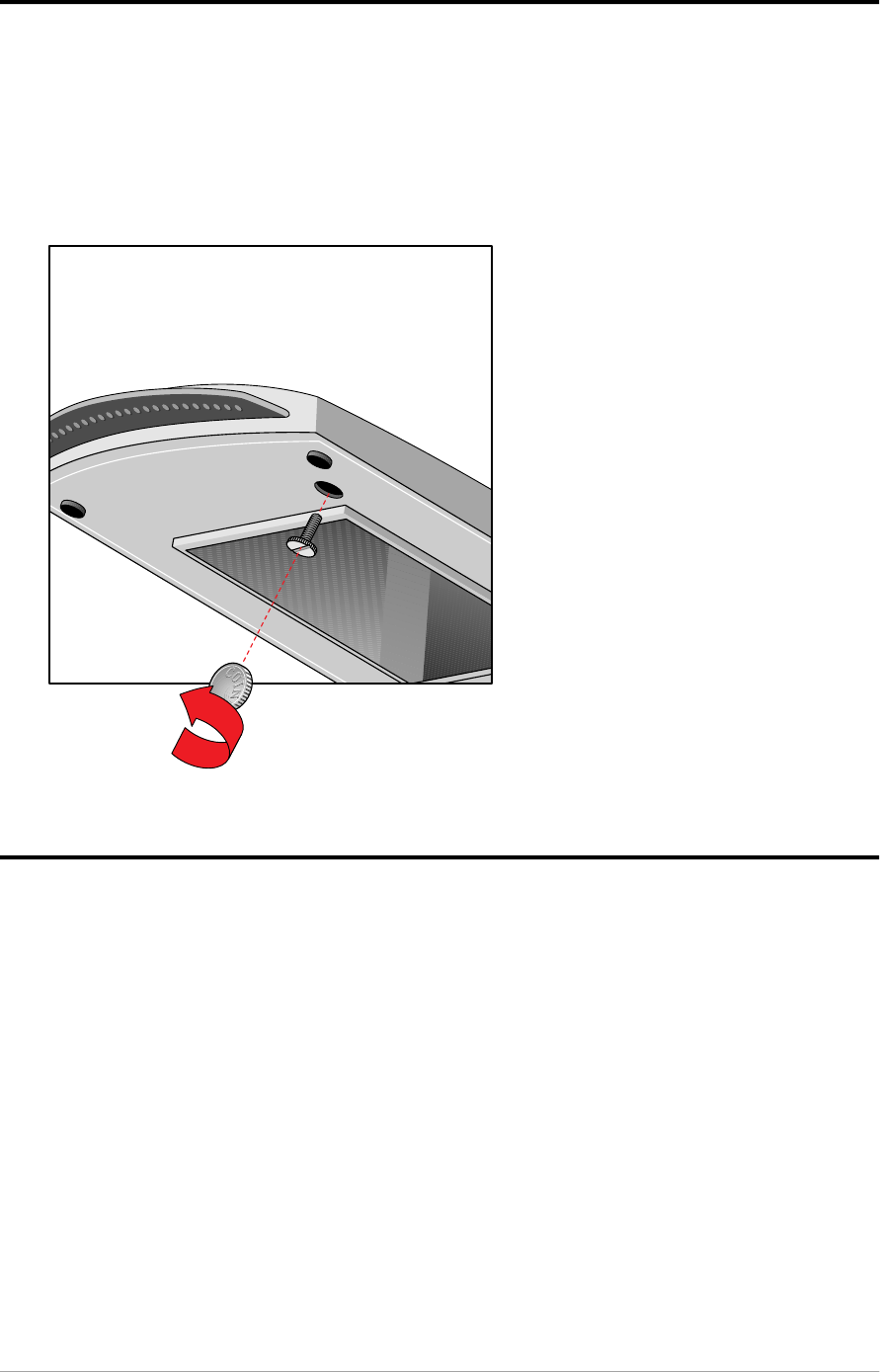
Unlocking the transparency option
Unlock the transparency option before connecting it to the scanner.
1. You will see the locking screw at the base of the transparency option.
2. Turn the screw counterclockwise and remove it. Keep it for later transport.
Your transparency option is unlocked.
Connecting the transparency option
1. Check if your scanner and your transparency option are properly unlocked.
2. Switch off your scanner.
3. Switch off your computer.
4. If the automatic document feeder is installed, disconnect it from your
scanner.
Appendix A — Using the transparency option 46
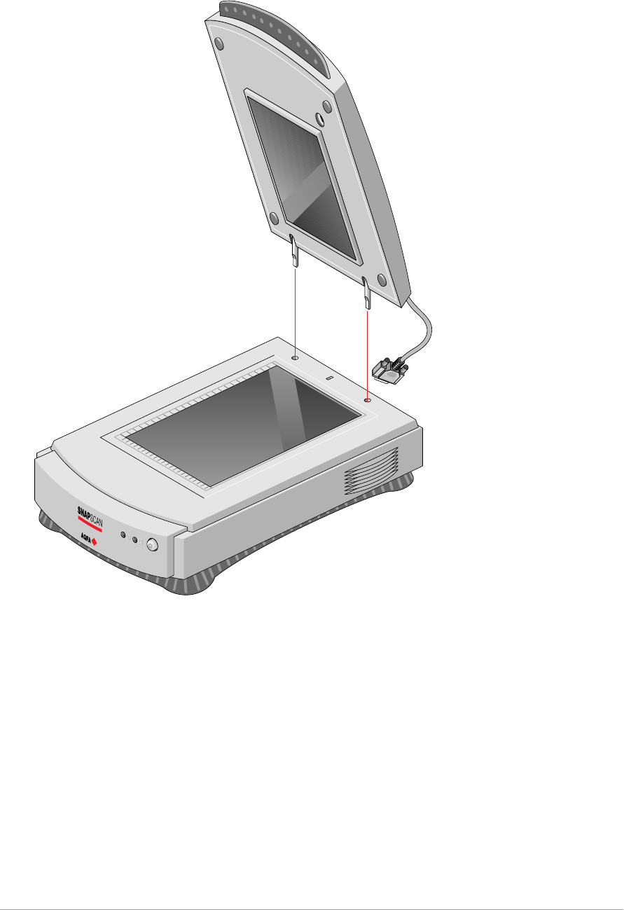
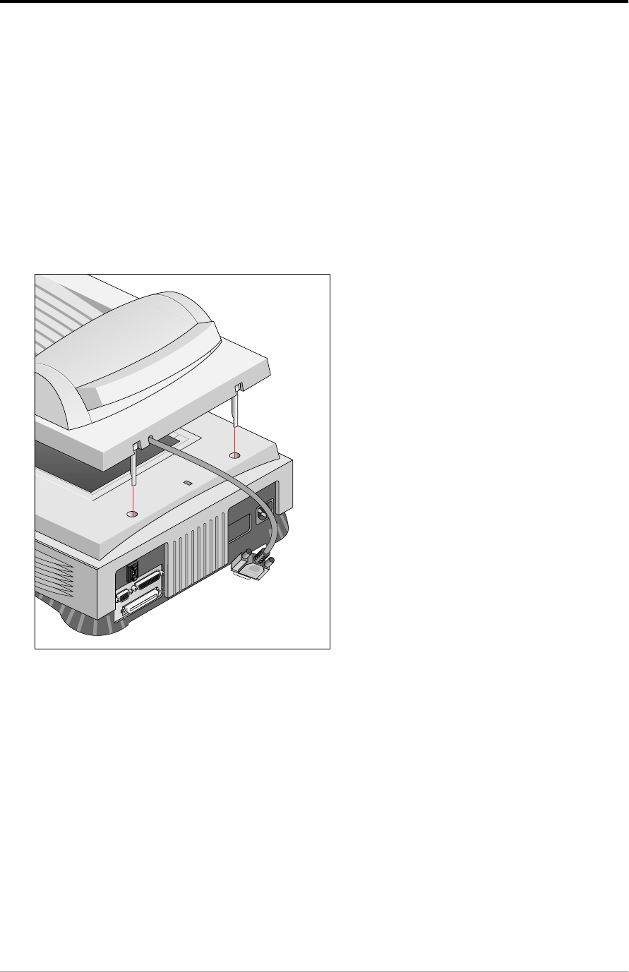
5. Connect the transparency option as shown in the figure. Insert the guide pins
into the holes originally used by the scanner’s document cover.
6. Lower the transparency option.
7. Connect the male 15-pin connector of the transparency option to the female
15-pin connector at the rear of the scanner. Secure the connector by
tightening its retaining screws.
Appendix A — Using the transparency option 47
The transparency option is ready for use.
9. Switch on your scanner.
10. Switch on your computer.
Appendix A — Using the transparency option 48
Placing transparent originals
Caution: Always use the template for scanning transparent originals. Make sure that
the calibration slit is not covered by the transparent original and that it is clean.
You need the transparency option to scan transparent originals.
1. Make sure the transparency option is properly installed.
2. Raise the transparency option.
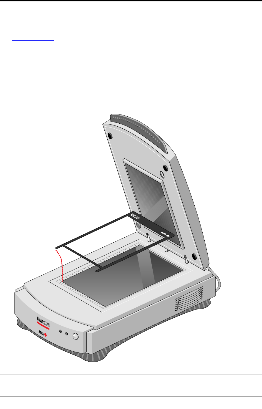
3. Place the template on the glass plate of your scanner. Make sure that the
calibration slit in the template is at the front side and that it is free.
Caution: Make sure that the calibration slit faces the front of the scanner and is not
covered by the transparent originals.
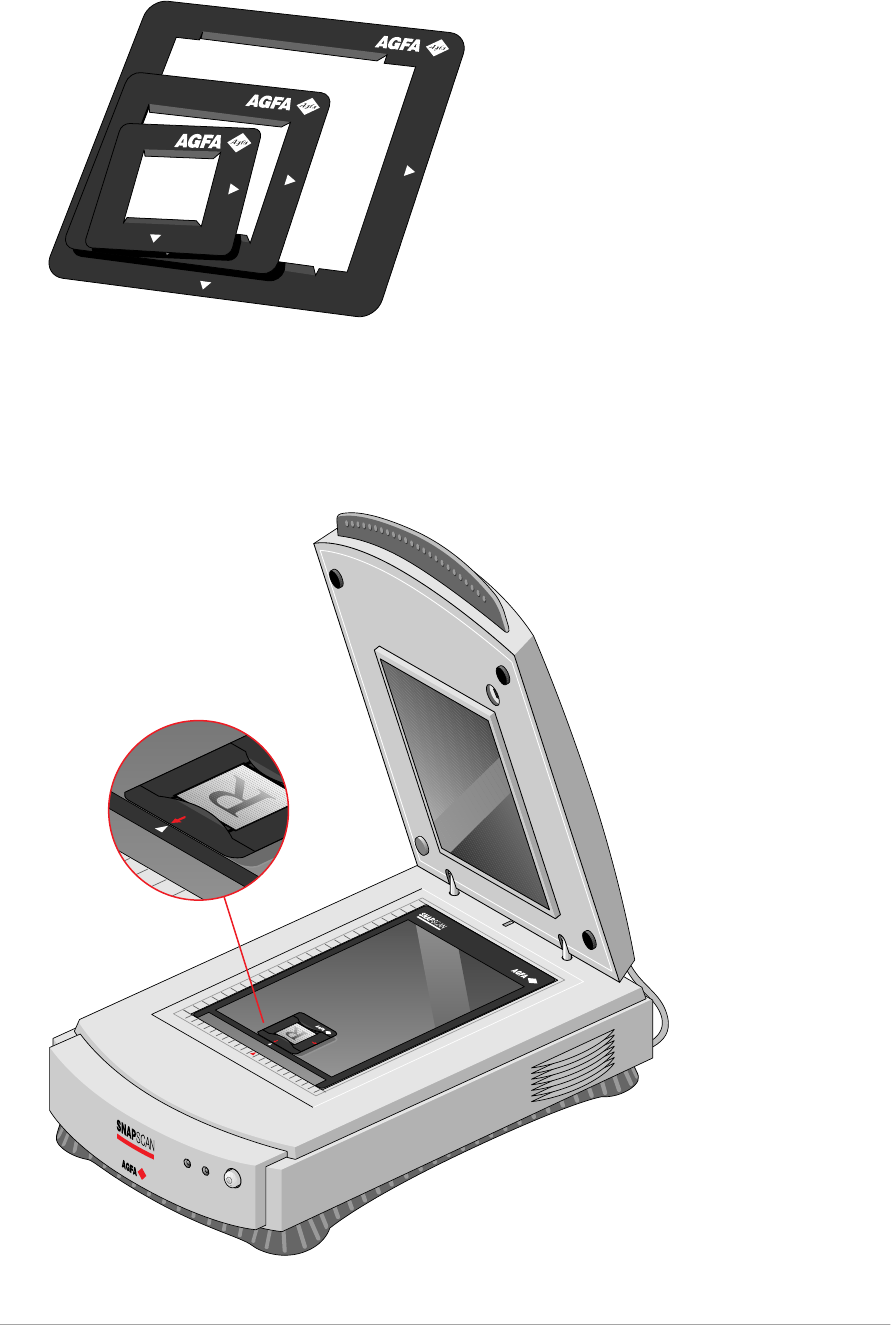
Appendix A — Using the transparency option 49
4. Put the original in one of the slide holders.
5. Place the slide holder on the glass plate with the emulsion down, that is, with
the matte side down, and with its top side towards the calibration slit. This
position guarantees the best quality.
If you place more than one slide on the glass plate, position them as close to
the center line as possible to optimize quality.
5. Lower the transparency option.

Appendix B — Using the automatic document feeder 50
Appendix B — Using the automatic document
feeder
This appendix gives information on the automatic document feeder and describes
how to install, operate and maintain it.
About your automatic document feeder
U n p ac k i n g t h e au t o m at i c d o c u m e n t f e e d e r
T ak in g a c lo s e r l o o k
C o n n e c t i n g t h e au t o m at i c d o c u m e n t f e e d e r
O p e rat i n g t h e au t o mat i c d o c u m e n t f e e d e r
P l ac in g t e x t p ag e s i n y o u r au t o m at i c d o c u m e n t f e e d e r
C o rre c t in g p ap e r j am s
C l e an in g t h e au t o mat i c d o c u m e n t f e e d e r
C l e an in g an d re p l ac in g t h e g u id e f l ap
R o l l e r c le an i n g
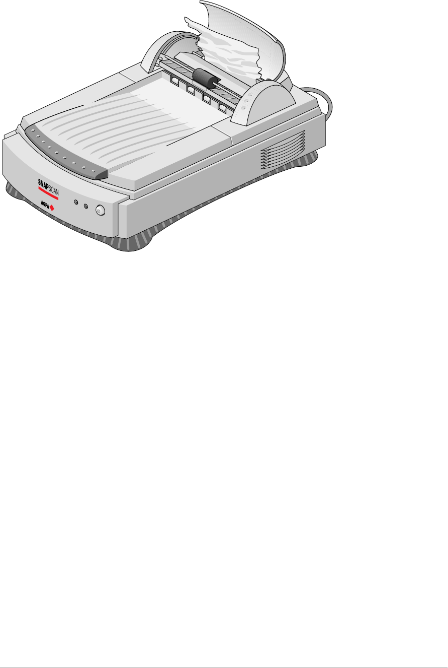
About your automatic document feeder (ADF)
The ADF automatic document feeder is an optional sheet feeder for your
SnapScan. It allows automatic scanning of up to 60 sheets. The dimension of the
document can be as large as 216 mm x 355 mm. Sheets to be scanned are fed
from a stack in the ADF's input tray. The feeder leads them past the scanner’s
image sensor, and places the sheets in the feeder's output tray.
The ADF is mounted onto the scanner in the same place as the document cover,
using the original document guide holes of your scanner. The feeder is
preloaded with spring plungers so that it can be lowered into position for auto-
feed or lifted to put an original directly on the glass plate.
The ADF is a must for high-volume document processing with your SnapScan. It
increases operating convenience and efficiency in multi-page scanning.

Appendix B — Using the automatic document feeder 51
Unpacking the automatic document feeder
The ADF is delivered ready to be mounted onto the scanner.
1. Open the packing box and take out all the items.
2. Check the ADF to make sure that there is no visible defect.
If there is a defect, contact your dealer.
3. Remove the plastic wrapping and the packing materials from the automatic
document feeder.
❖Note: Save the packing materials to protect the automatic document
feeder during later transport.
To register, you can fill in the registration form on the Agfa Scanners CD ROM
at any time. See Electronic registration .
Appendix B — Using the automatic document feeder 52
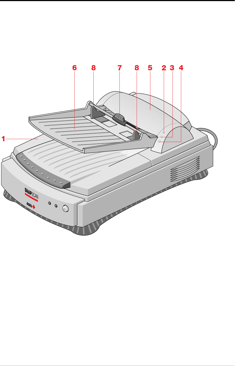
Taking a closer look
Now that you have the automatic document feeder out of the box, take a closer
look so that you become familiar with its parts.
1. transportation module
2. power indicator (green)
3. original indicator (orange)
4. paper jam indicator (orange)
5. cover of the transportation module
6. paper tray
7. rotating arm
8. guide arms
Appendix B — Using the automatic document feeder 53
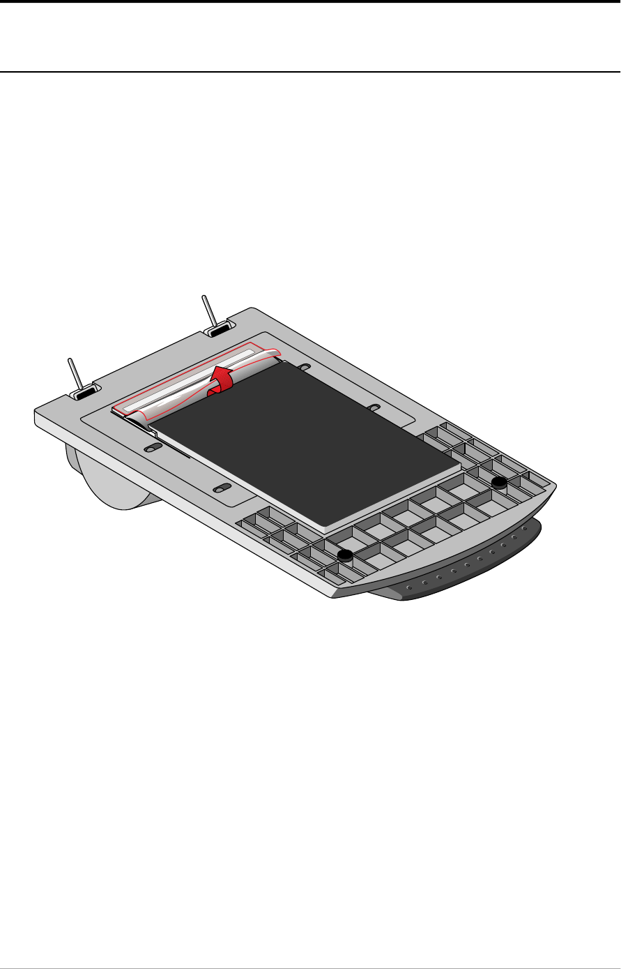
Connecting the automatic document feeder
You install the automatic document feeder as follows:
1. Check if your scanner is properly unlocked.
2. Turn off your scanner.
3. Turn off your computer.
4. If the transparency option is installed, disconnect it from your scanner.
5. Remove the document cover from the scanner.
6. Place the ADF on top of the scanner. Insert the guide pins into the holes
originally used by the scanner's document cover.
Appendix B — Using the automatic document feeder 54
7. Connect the male 15-pin connector of the automatic document feeder to the
female 15-pin connector at the rear of the scanner. Secure the connector by
tightening its retaining screws.
8. Open the cover of the transportation module.
9. Lift the rotating arm of the paper tray.
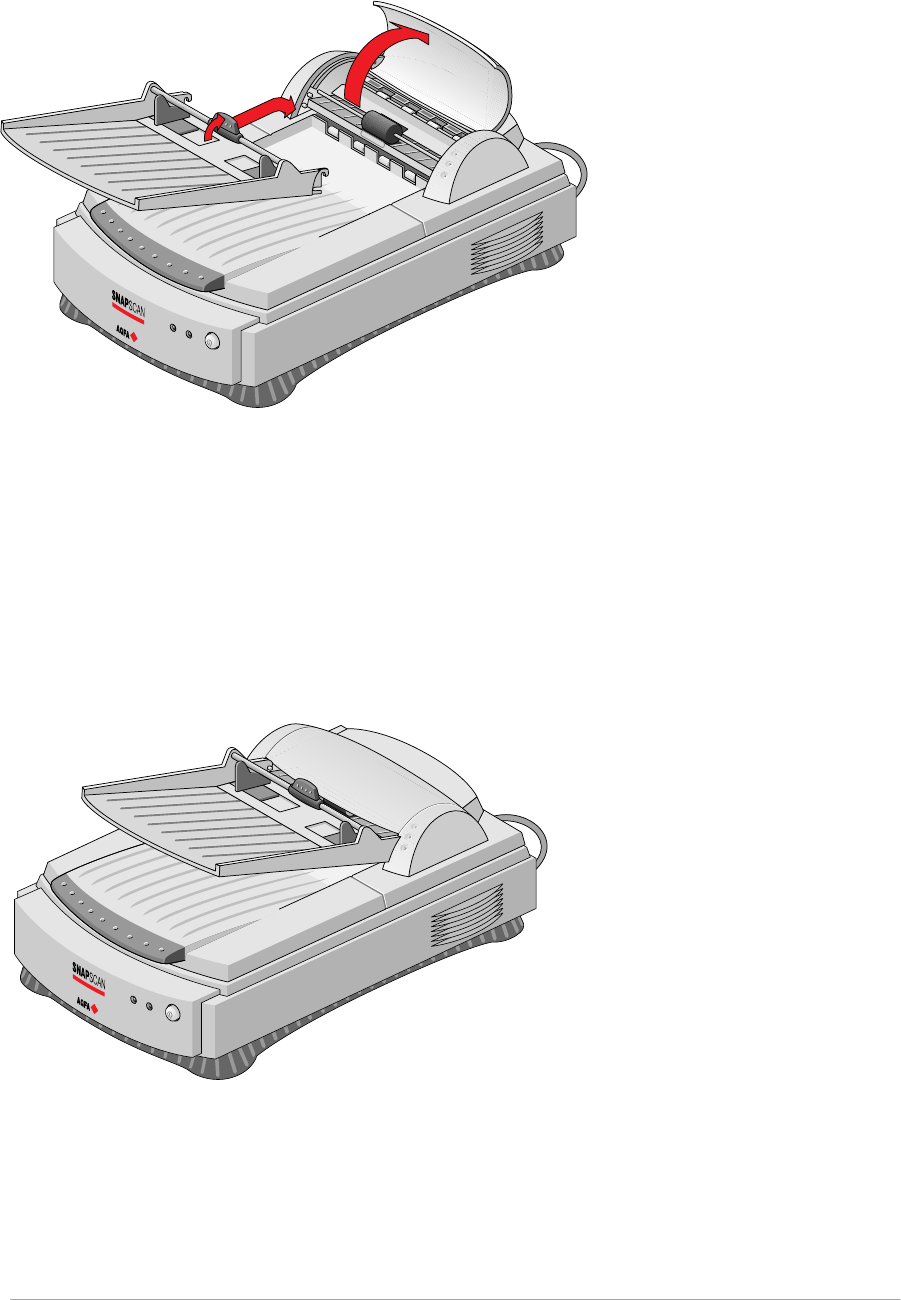
Appendix B — Using the automatic document feeder 55
10. Hook the paper tray into the transportation module.
11. Lower the rotating arm.
12. Close the cover of the transportation module.
13. Switch on your scanner.
14. Switch on your computer.
Software like OmniPage Limited Edition makes it possible to convert the
scanned sheets of text into most of the commercially used text file formats.
Appendix B — Using the automatic document feeder 56
Operating the automatic document feeder
When the ADF is installed and the scanner is powered on, start up the
Omnipage™ software. You can find the software on the Software Collection CD-
ROM.
Placing text pages in your automatic document feeder
The purpose of the automatic document feeder is to scan up to 60 text pages fast
and without interruption. Software like OmniPage Limited Edition® or other OCR
(Optical Character Recognition) software makes it possible to convert them into
most of the commercially used text file formats.
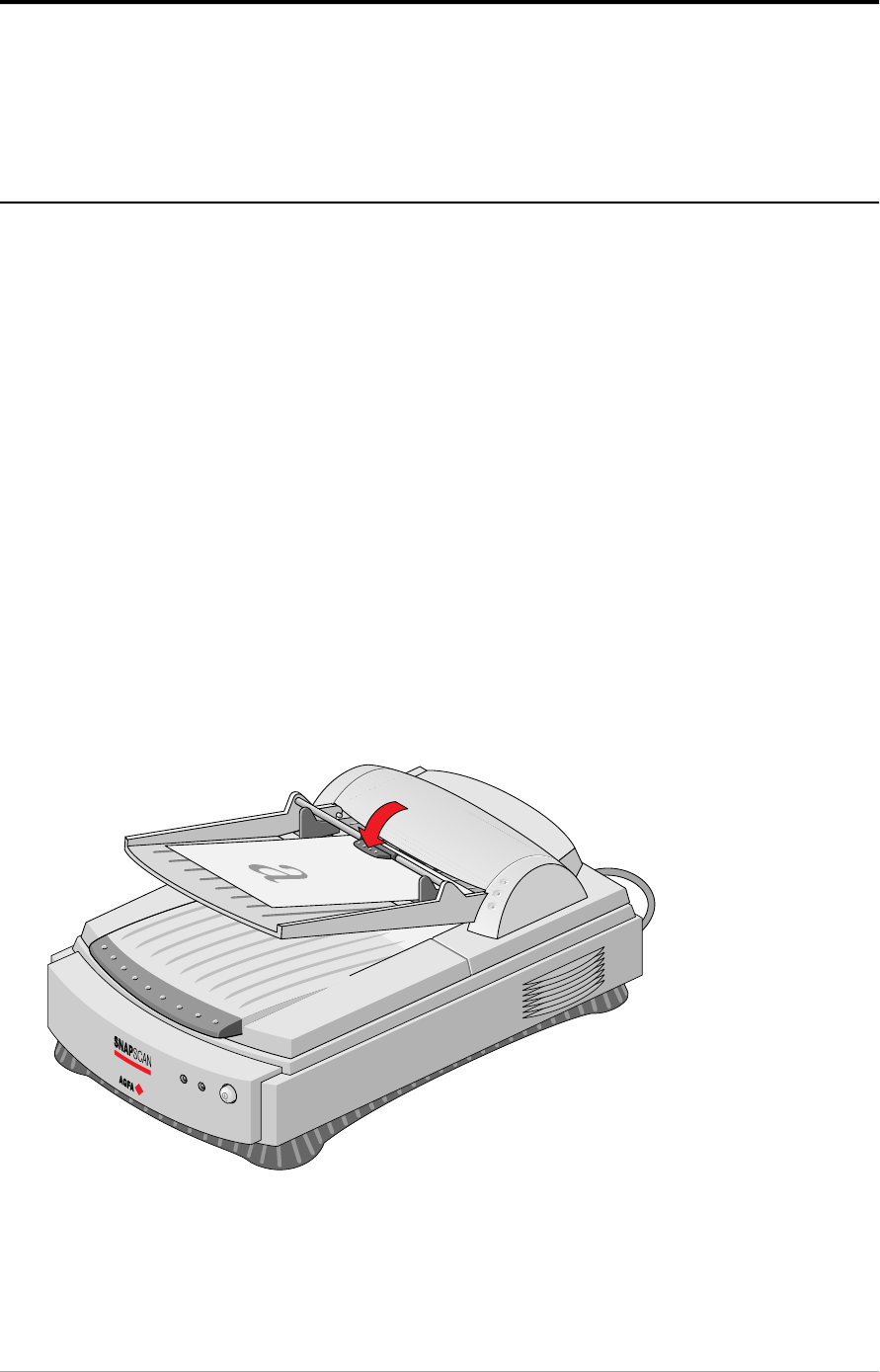
1. Make sure your automatic document feeder is properly installed.
2. Lower the automatic document feeder.
3. Lift the rotating arm of the paper tray.
4. Put a pile of maximum 60 text pages on the paper tray of your automatic
document feeder. Make sure the text is facing up.
5. Lower the rotating arm of the paper tray.
Appendix B — Using the automatic document feeder 57
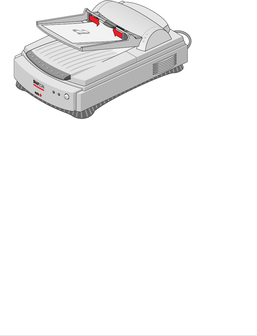
6. Use the two guide arms to align the paper in the center.
Appendix B — Using the automatic document feeder 58
Correcting paper jams
To remove jammed pages:
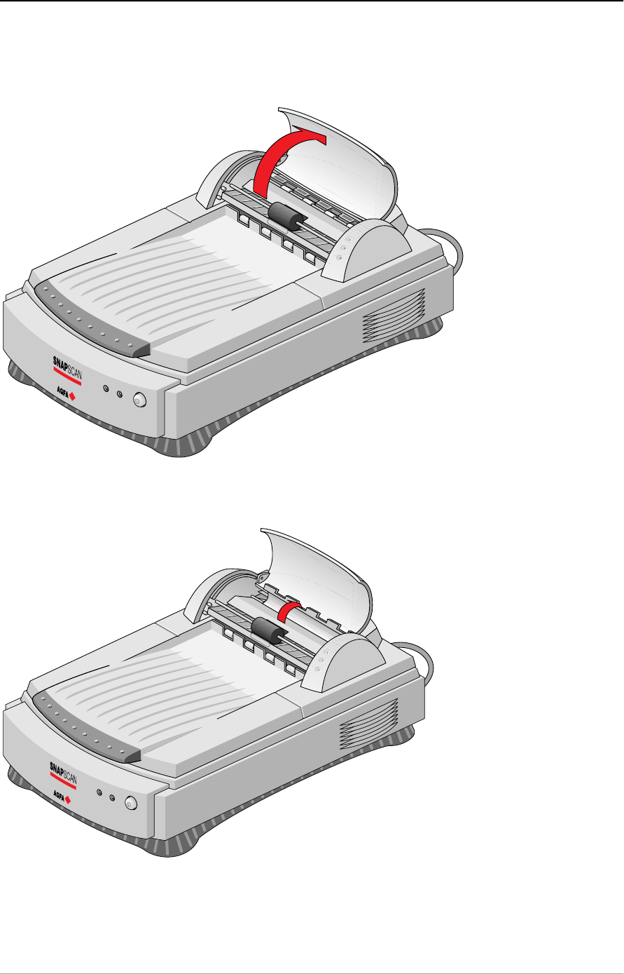
1. Open the cover of the transportation module.
2. Lift the paper-turn-around plate.
Appendix B — Using the automatic document feeder 59
3. Grasp both free corners of the jammed sheet and pull it out slowly.
4. Lower the paper-turn-around plate. Make sure that the paper-turn-around
plate is properly closed.
5. Close the cover of the transportation module. Make sure that it is properly
closed.
Appendix B — Using the automatic document feeder 60
Cleaning the automatic document feeder
Cleaning the transparent guide flap
The guide flap on the underside of the ADF keeps documents in the correct
scanning position and guides them into the output tray after scanning. To
prevent printing ink and other contaminants from accumulating on the flap and
interfering with image quality, wipe it periodically with an ink-free cloth or
moistened cotton swab. Clean it on both sides.
To clean the transparent guide flap inside:
1. Carefully open the transparent guide flap on the bottom of the ADF. Do not
remove the transparent guide flap.
2. Carefully close the transparent guide flap after cleaning.
Appendix B — Using the automatic document feeder 61
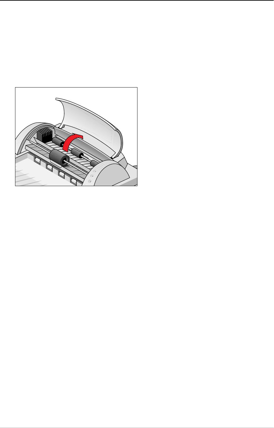
Roller cleaning
Prolonged use of the ADF may result in an accumulation of ink and other
contaminants on the feeder's input roller. This reduces the efficiency of the
roller. Check for dirt on the roller if the ADF starts to have trouble pulling paper
through properly. The input roller should be cleaned periodically using a lint-fee
cloth or moistened cotton swab .
❖Note: Do not attempt to turn the roller while cleaning it. This may damage the
ADF's drive mechanism.

Appendix C — Troubleshooting 62
Appendix C — Troubleshooting
This appendix gives solutions for some common problems you may come across
when starting up or using your SnapScan.
The computer screen displays scanner calibration error.
■The calibration slit is covered by your transparent original. You did not use
the template or you used it incorrectly. This can only happen when you are in
transparency mode.
The scanner or transparency option lamp flickers, dims, or fails to
come on.
■The daylight fluorescent lamp needs to be changed. Contact your dealer.
The scanner driver software returns a “Scanner not ready” or similar
message.
■Verify the power connection to the scanner
■Check that the power switch is turned on.
■Check the Installation procedure, to see if you followed the instructions. Pay
special attention to the setting of the SCSI ID number.
■Verify the terminators and the cables. If there is a problem with a cable or with
the SCSI board of the scanner, contact your dealer.
■Disconnect all SCSI devices and connect them one by one, beginning with
the scanner, to identify the device that causes the problem.
The scanner does not start up.
■Contact your dealer.
The scanner makes an unusual noise and nothing moves under the
glass plate when you switch the scanner on.
■The scanner was not properly unlocked. Immediately switch off the scanner
and unlock it properly, or contact your dealer.
The status indicator (the left green one) on the scanner’s operating
panel starts blinking at a higher frequency after the power-up
sequence (= 15 seconds).
A malfunction has been detected by the scanner.
■Check if you have unlocked the scanner.
■Switch off the scanner and switch it back on.
■If this does not help, please contact your dealer.

Appendix C — Troubleshooting 63
The power indicator (the right green one) and the status indicator
fail to light up.
■Verify the power connection to the scanner.
■Check if the power switch is turned on.
■If you are sure that the scanner is powered on, contact your dealer.
The computer does not start up. If your computer is a Macintosh, a
little floppy disk with a question mark appears on your screen.
Your computer cannot find its hard disk due to a conflict with the SCSI ID numbers
of the devices you have attached.
■Disconnect all SCSI devices (except the start-up disk) and connect them one
by one, beginning with the scanner, to identify the device that causes the
problem (switch off all devices before connecting or disconnecting them).
The scanner software cannot find the scanner
After opening the Scan dialog box, a message appears telling you that no
scanner is connected, although the scanner is connected.
■Check the Installation procedure, to see if you followed the instructions. Pay
special attention to the setting of the SCSI ID number.
■Maybe you did not wait long enough for all SCSI devices to start up, before
you switched your computer on. Try restarting your computer.
■Disconnect all SCSI devices and connect them one by one, beginning with
the scanner, to identify the device that causes the problem.
The scanner reports errors during scanning
■Check if you have connected a SCSI terminator. If this can not be the
problem, please contact your dealer.
❖Note: If you encounter other problems during or after installation, please refer
to the FotoLook ReadMe file on your computer, or the SCSICARD help file on
the Agfa Scanners CD-ROM.

Appendix D — Technical information on the Snapscan 300 64
Appendix D — Technical information on the
SnapScan 300
This appendix provides some technical information about your SnapScan 300,
about the transparency option and about the automatic document feeder.
SnapScan 300 specifications
T ran s p are n c y o p t i o n s p e c i f i c at i o n s
D o c u me n t f e e d e r o p t i o n s p e c if i c at i o n s
Technical specifications are subject to change without notice.
SnapScan 300 specifications
Scanner type: Desktop, flatbed, one pass
Maximum resolution:
- optical: 300 ppi horizontal x 600 ppi vertical
- through interpolation: 4800 ppi horizontal x 4800 ppi vertical
Sample depth: 8 bits for gray, 24 bits for color
Scanning speed:
- line-art: 3 ms / line
- gray: 3 ms / line
- color: 10 ms / line
Maximum scanning area: 216 x 297 mm (8.5 '' x 11.7 '')
Lamp: fluorescent daylight
Power-on to ready time: ≤ 15 seconds
Power supply:
- voltage: 100 V to 240 V
- frequency: 47 Hz to 63 Hz
Dimensions:
- length: 530 mm
- width: 375 mm
- height: 140 mm
- weight: ca. 5.6 kg

Appendix D — Technical information on the Snapscan 300 65
Options: Transparency Option
Automatic document feeder
Interface: SCSI-2
1 x 25-pins connector
1 x 50-pins connector
Transmission speed: 2 Mbyte/s
Environmental specifications:
- operating temperature: +10 °C to +40 °C (+50 to +104 degrees
Fahrenheit)
- relative humidity: 20% to 85% RH
- surrounding space: 10 cm on every side
Transparency option specifications
System: Moving light source
Maximum resolution: 300 ppi horizontal x 600 ppi vertical
Scanning area: 203 mm x 254 mm (8 '' x 10 '')
Lamp: fluorescent daylight
Power supply: from the scanner
Interface: 15-pin cable with connector to scanner
Dimensions:
- length: 450 mm
- width: 330 mm
- height: 65 mm
- weight: 2.2 kg
Environment:
- operating temperature: +10 °C to +40 °C (+50 to +104 degrees
Fahrenheit)
- relative humidity: 20% to 85% RH
- surrounding space: 10 cm on every side
Connection with scanner External connection: 15 pin sub D

Appendix D — Technical information on the Snapscan 300 66
Automatic document feeder specifications
Number of originals in
document tray:
- minimum
- maximum
1
60
Original Document size:
- minimum: 100 mm (W) x 150 (H) mm
- maximum: 216 mm (W) x 355 (H) mm
Document skew: Max ≤1 %
Connector: 15-pin cable with connector to scanner
Dimensions:
- length: 465 mm
- width: 330 mm
- height: 130 mm
- weight: 3.5 kg
Power supply: from the scanner
Operating conditions:
- temperature: +10 °C to +40 °C (+50 to +104 degrees
Fahrenheit)
- relative humidity 20 % to 85 %
Connection with scanner External connection

Appendix E — Technical information on the Snapscan 600 67
Appendix E — Technical information on the
SnapScan 600
This appendix provides some technical information about your SnapScan 600,
about the transparency option and about the automatic document feeder.
SnapScan 600 specifications
T ran s p are n c y o p t i o n s p e c i f i c at i o n s
D o c u me n t f e e d e r o p t i o n s p e c if i c at i o n s
Technical specifications are subject to change without notice.
SnapScan 600 specifications
Scanner type: Desktop, flatbed, one pass
Maximum resolution:
- optical: 600 ppi horizontal x 1200 ppi vertical
- through interpolation: 4800 ppi horizontal x 4800 ppi vertical
Sample depth: 10 bit per color (internal)
Scanning speed:
- line-art: 3.3 ms / line
- gray: 3.3 ms / line
- color transparent: 8 ms / line
- color reflective 5 ms / line
Scanning area:
Maximum 216 x 297 mm (8.5 '' x 11.7 '')
Lamp: fluorescent daylight
Power-on to ready time: ≤ 15 seconds
Power supply:
- voltage: 100V to 240V
- frequency: 47 Hz to 63 Hz
Dimensions:
- length: 530 mm
- width: 375 mm
- height: 140 mm
- weight: 5.6 kg

Appendix E — Technical information on the Snapscan 600 68
Options: Transparency option
Automatic document feeder
Interface: SCSI-2
1 x 25-pins connector
1 x 50-pins connector
Transmission speed: 2 Mbyte/s
Environmental specifications:
- operating temperature: +10 °C to +40 °
(+50 to +104 degrees Fahrenheit)
- relative humidity: 20% to 85% RH
- surrounding space: 10 cm on every side
Transparency option specifications
System: Moving light source
Resolution: 600 ppi horizontal x 1200 ppi vertical
Scan area: 203 mm x 254 mm (8 '' x 10 '')
Lamp: fluorescent daylight
Power supply: from the scanner
Interface: 15-pin cable with connector to scanner
Dimensions:
- length: 450 mm
- width: 330 mm
- height: 65 mm
- weight: 2.2 kg
Environment:
- operating temperature: +10 °C to +40 °C (+50 to +104 degrees
Fahrenheit)
- relative humidity: 20% to 85% RH
- surrounding space: 10 cm on every side
Connection with scanner External connection: 15 pin sub D

Appendix E — Technical information on the Snapscan 600 69
Automatic document feeder specifications
Number of originals in
document tray:
- minimum 1
- maximum 60
Original Document size:
- minimum: 100 mm (W) x 150 (H) mm
- maximum: 216 mm (W) x 355 (H) mm
Document skew: Max ≤1 %
Connector: 15-pin cable with connector to scanner
Dimensions:
- length: 465 mm
- width: 330 mm
- height: 130 mm
- weight: 3.5 kg
Power supply: from the scanner
Operating conditions:
- temperature: +10 °C to +40 °C (+50 to +104 degrees
Fahrenheit)
- relative humidity 20 % to 85 %
Connection with scanner External connection

Appendix F — SnapScan regulation compliance 70
Appendix F — SnapScan regulation
compliance
Safety regulations
E l e c t ro mag n e t i c i n t e rf e re n c e
Safety regulations
SnapScan and its options are designed to comply with:
UL 1950-D3
CSA C22.2 No. 950 - M89 D3
VDE 805
IEC 950
GS approved
EN 60950
UL Safety Statement
Instructions for power supply cord selection:
For modules set at 115V:
Use a UL listed, Type SVT or SJT cord, three conductor, rated 10 A 125 V, not to
exceed 15ft in length.
Caution: For the reason of safety, besides the personal maintenance mentioned in this
operation manual, don’t try to remove any mechanical parts or any electronic devices. If
you need service, our dealer and service offices are available to help you.
FTZ: Bescheinigung des Herstellers/Importeurs
Hiermit wird bescheinigt dass der Image Scanner in Übereinstimmung mit den
Bestimmungen der vfg 243/1991 funk-entstört ist.
Der Deutschen Bundespost wurde das inverkehrbringen dieses Gerätes
angezeigt und Berechtigung zur Überprüfung der Serie auf Einhaltung der
Bestimmungen eingeraumt.

Appendix F — SnapScan regulation compliance 71
TÜV: Wichtige Sicherheitshinweise
1. Bitte Lesen Sie sich diese Hinweise sorgfältig durch.
2. Um eine Beschädigung des Gerätes zu vermeiden sollten Sie nur
Zuberhörteile verwenden, die vom Hersteller zugelassen sind.
3. Das Gerät ist vor Feuchtigkeit zu schützen.
4. Bei der Aufstellung des Gerätes ist auf sicheren Stand zu achten. Ein Kippen
oder Fallen könnte Verletzungen hervorrufen. Verwenden Sie nur sichere
Standorte und beachten Sie die Aufstellhinweise des Herstellers.
5. Die Belüftungsöffnungen dienen zur Luftzirkulation die das Gerät vor
Überhitzung schütz. Sorgen Sie dafür, daß diese Öffnungen nicht abgedeckt
werden.
6. Die Netzanschulßsteckdose muß aus Gründen der elektrischen Sicherheit
einen Schutzleiterkontakt haben.
7. Durch die Lüftungsöffnungen dürfen niemals Gegenstände oder
Flüssigkeiten in das Gerät gelangen. Dies könnte einen Brand bzw.
elektrischen Schlag auslösen.
8. Öffnen Sie niemals das Gerät. Das Gerät darf aus Gründen der elektrischen
Sicherheit nur von authorisiertem Servicepersonal geöffnet werden.
9. Die Steck dose sollte nahe dem Gerät und leicht zugänglich sein.
Electromagnetic interference
SnapScan is designed to comply with:
VDE 0871, class B
VDE 0875, level N
FCC 20718, part 15, subpart B, class B
Federal Communications Commission Radio Frequency
Interference Statement
Note: This equipment has been tested and found to comply with the limits for a
Class B digital device, pursuant to Part 15 of the FCC Rules. These limits are
designed to provide reasonable protection against harmful interference when the
equipment is operated in a residential installation. This equipment generates,
uses, and can radiate radio frequency energy and if not installed and used in
accordance with the instruction manual may cause harmful interference to radio
communications. However, there is no guarantee that interference will not occur
in a particular installation. If this equipment does cause harmful interference to
radio or television reception, which can be determined by turning the equipment
off and on, the user is encouraged to try to correct the interference by one or
more of the following measures:

Appendix F — SnapScan regulation compliance 72
■Reorient or relocate the receiving antenna.
■Increase the separation between the equipment and receiver.
■Connect the equipment into an outlet on a circuit different from that to which
the receiver is connected.
■Consult the dealer or an experienced radio TV technician for help.
Notice:
(1) The changes or modifications not expressly approved by the party responsible
for compliance could void the user’s authority to operate the equipment.
(2) Shielded interface cables and AC power cord, if any, must be used in order to
comply with the emission limits.
Canadian department of Communications
This digital apparatus does not exceed the Class B limits for radio noise
emissions from digital apparatus set out in the Radio Interference Regulations of
the Canadian Department of Communications.
Le présent appareil numérique n’émet pas de bruits radioélectriques dépassant
les limites applicables aux appareils numériques (de la classe B) prescrites dans
le Règlement sur le brouillage radioélectrique édicté par le ministère des
Communications du Canada.
