Agilent Technologies 85225F Users Manual Standard Performance Ing System Installation And User’s Guide
85225F 18-27772
85225F to the manual ae794363-6764-4394-ace8-4f999ac81e09
2015-02-02
: Agilent-Technologies Agilent-Technologies-85225F-Users-Manual-413223 agilent-technologies-85225f-users-manual-413223 agilent-technologies pdf
Open the PDF directly: View PDF ![]() .
.
Page Count: 148 [warning: Documents this large are best viewed by clicking the View PDF Link!]
- Title Page
- Safety and Regulatory Information
- In This Guide...
- Contents
- Introducing the Agilent 85225F Performance Modeling System
- Performance Modeling System Configuration Overview
- RF and DC Measurement System Configuration
- Figure 1 System Block Diagram
- The RF Subsystem
- The DC Subsystem
- The Bias Networks
- Component Integration
- Figure 2 System Components
- Table 3 Front Panel System Connections, with Agilent 4156C
- Figure 3 Front Panel Connections with Agilent 4156C
- Table 4 Front Panel System Connections, with Agilent E5260A or E5270B
- Figure 4 Front Panel Wiring Diagram with Agilent E5260A or E5270B
- Table 5 Rear Panel System Connections with Agilent 4156C
- Figure 5 Rear Panel Wiring Diagram with Agilent 4156C
- Table 6 Rear Panel System Connections with Agilent E5260A or E5270B
- Figure 6 Rear Panel Wiring with Agilent E5260A or E5270B
- Figure 7 DC/RF Cabling Diagram - DC and RF Configuration
- CV, RF, and DC Measurement System Configuration
- 1/f Noise, CV, RF, and DC Measurement System Configuration
- Instrument Control Interface
- The LAN/GPIB Gateway
- Performance Characteristics and Specifications
- Installing the System
- Verifying System Functionality
- Servicing the System
- Enhancing Measurement Accuracy
- DC Subsystem Functional Verification Test
- RF Subsystem Functional Verification Test
- CV Subsystem Functional Verification Test
- 1/f Noise Subsystem Functional Verification Test
- Understanding the Bias Networks
- Network Analyzer Performance Specification Summary
- Index

Agilent Technologies
Agilent 85225F
Performance Modeling System
Installation and User’s Guide
Notices
© Agilent Technologies, Inc. 2005
No part of this manual may be reproduced
in any form or by any means (including
electronic storage and retrieval or transla-
tion into a foreign language) without prior
agreement and written consent from Agi-
lent Technologies, Inc. as governed by
United States and international copyright
laws.
Manual Part Number
85225-90023
Edition
First edition, April 2005
Printed in USA
Agilent Technologies, Inc.
1400 Fountaingrove Parkway
Santa Rosa, CA 95403 USA
Warranty
The material contained in this docu-
ment is provided “as is,” and is sub-
ject to being changed, without notice,
in future editions. Further, to the max-
imum extent permitted by applicable
law, Agilent disclaims all warranties,
either express or implied, with regard
to this manual and any information
contained herein, including but not
limited to the implied warranties of
merchantability and fitness for a par-
ticular purpose. Agilent shall not be
liable for errors or for incidental or
consequential damages in connection
with the furnishing, use, or perfor-
mance of this document or of any
information contained herein. Should
Agilent and the user have a separate
written agreement with warranty
terms covering the material in this
document that conflict with these
terms, the warranty terms in the sep-
arate agreement shall control.
Technology Licenses
The hardware and/or software described in
this document are furnished under a
license and may be used or copied only in
accordance with the terms of such license.
Restricted Rights Legend
If software is for use in the performance of
a U.S. Government prime contract or sub-
contract, Software is delivered and
licensed as “Commercial computer soft-
ware” as defined in DFAR 252.227-7014
(June 1995), or as a “commercial item” as
defined in FAR 2.101(a) or as “Restricted
computer software” as defined in FAR
52.227-19 (June 1987) or any equivalent
agency regulation or contract clause. Use,
duplication or disclosure of Software is
subject to Agilent Technologies’ standard
commercial license terms, and non-DOD
Departments and Agencies of the U.S. Gov-
ernment will receive no greater than
Restricted Rights as defined in FAR
52.227-19(c)(1-2) (June 1987). U.S. Govern-
ment users will receive no greater than
Limited Rights as defined in FAR 52.227-14
(June 1987) or DFAR 252.227-7015 (b)(2)
(November 1995), as applicable in any
technical data.
Acknowledgments
UNIX® is a registered trademark of the
Open Group.
Windows NT® is a U.S. registered trade-
mark of Microsoft Corporation.
Windows® and MS Windows are U.S. reg-
istered trademarks of Microsoft Corpora-
tion.

Installation and User’s Guide 3
Safety and Regulatory Information
Warnings, Cautions, and Notes
This installation and user’s guide utilizes the following safety notations.
Familiarize yourself with each notation and its meaning before operating
the Agilent 85225F performance modeling system.
WARNING A WARNING notice denotes a hazard. It calls attention to an operating
procedure, practice, or the like that, if not correctly performed or
adhered to, could result in personal injury or death. Do not proceed
beyond a WARNING notice until the indicated conditions are fully
understood and met.
CAUTION A CAUTION notice denotes a hazard. It calls attention to an operating
procedure, practice, or the like that, if not correctly performed or adhered
to, could result in damage to the product or loss of important data. Do not
proceed beyond a CAUTION notice until the indicated conditions are fully
understood and met.
NOTE A NOTE calls the user’s attention to an important point or special
information within the text. It provides additional information or
instructions.
4Installation and User’s Guide
Safety Symbols and Instrument Markings
Symbols and markings in documentation and on instruments alert you to
potential risks, provide information about conditions, and comply with
international regulations. Table A defines the safety symbols and Table B
on page 5 defines the instrument markings you may find in the
documentation or on an instrument.
Table A Safety Symbols
Symbols Definition
Warning: risk of electric shock.
Warning: hot surface.
Caution: refer to instrument documentation.
Laser radiation symbol: marked on products that have a laser
output.
Alternating current.
Both direct and alternating current.
Three-phase alternating current.
Earth (ground) terminal.
Protective earth (ground) terminal.
Frame or chassis terminal.
Terminal is at earth potential. Used for measurement and
control circuits designed to be operated with one terminal at
earth potential.
Terminal for neutral conductor on permanently installed
equipment.
Terminal for line conductor on permanently installed
equipment.
Installation and User’s Guide 5
Operator Safety Requirements
The following general safety precautions must be observed during all
phases of operation of this system. Failure to comply with these
precautions or with specific warnings elsewhere in this manual violates
Standby (supply). Units with this symbol are not completely
disconnected from AC mains when this switch is in the standby
position. To completely disconnect the unit from AC mains,
either disconnect the power cord, or have a qualified/licensed
electrician install an external switch.
ON (supply). A switch with this symbol closes the instrument’s
power supply circuit, connecting it to the mains supply.
OFF (supply). A switch with this symbol opens the instrument’s
power supply circuit, disconnecting it from the mains supply.
Table B Instrument Markings
Marking Definition
The instruction documentation symbol appears when it is
necessary for the user to refer to the instruction in the
documentation.
The CE mark is a registered trademark of the European
Community.
This product complies with the WEEE Directive (2002/96/EC)
marking requirements. The affixed label indicates that you must
not discard this electrical/electronic product in domestic
household waste. To return unwanted products, contact your
local Agilent Technologies office, or see www.agilent.com for
more information.
The CSA mark is a registered trademark of the
CSA-International.
The C-tick mark is a registered trademark of the Spectrum
Management Agency of Australia. This signifies compliance
with the Australian EMC Framework regulations under the
terms of the Radio Communications Act of 1992.
ISM1-A This text indicates that the instrument is an Industrial Scientific
and Medical Group 1 Class A product (CISPER 11, Clause 4).
ICES/NMB-001 This text indicates product compliance with the Canadian
Interference-Causing Equipment Standard (ICES-001).
Table A Safety Symbols (continued)
Symbols Definition
N10149

6Installation and User’s Guide
safety standards of design, manufacture, and intended use of the product.
Agilent Technologies, Inc. assumes no liability for the customer’s failure to
comply with these requirements.
For additional safety precautions, including precautions for making device
measurements in a floating ground configuration, see “To ensure your
safety while using the system" on page 76.
WARNING This is a Safety Class 1 Product (provided with a protective earthing
ground incorporated in the mains supply cord). The mains plug shall
be inserted only in a socket outlet provided with a protective earth
contact. Any interruption of the protective conductor inside or
outside of the product is likely to make the product dangerous.
Intentional interruption is prohibited.
WARNING If this product is not used as specified, the protection provided by the
equipment could be impaired. This product must be used only in a
normal condition (in which all means for protection are intact) only.
WARNING DO NOT OPERATE IN AN EXPLOSIVE ATMOSPHERE. Do not operate
the instrument in the presence of flammable gases or flames.
WARNING DO NOT REMOVE THE INSTRUMENT COVER. Operating personnel
must not remove instrument covers. Component replacement and
internal adjustments must be made only by qualified service
personnel. Instruments that appear damaged or defective should be
made inoperative and secured against unintended operation until
they can be repaired by qualified service personnel.
WARNING Installing additional instruments may destabilize the rack cabinet.
WARNING Installing additional instruments into the cabinet electrical system
could produce excessive leakage current. If the protective earth
conductor is interrupted or faulted, the user risks serious injury or
death.
WARNING Prior to adding any additional instruments, review all wiring and
cooling capabilities to verify adequate design margins for normal and
under single fault conditions.

Installation and User’s Guide 7
Mains power
Ground the system
Before applying power
CAUTION The mains cable shall be permanently connected to the premise circuit
breaker or connected using an agency approved twist-lock connector.
WARNING To minimize shock hazard, the rack cabinet must be connected to an
electrical protective earth ground. The power distribution unit (PDU)
must be connected to the AC power mains through a grounded power
cable, with the ground wire firmly connected to an electrical ground
(safety ground) at the power outlet.
WARNING Any interruption of the protective (grounding) conductor or
disconnection of the protective earth terminal will cause a potential
shock hazard that could result in personal injury.
CAUTION Verify that the product is set to match the available line voltage, the
correct fuse is installed, and all safety precautions are taken. Before
applying power, note the product’s external markings described in
Table A, “Safety Symbols,” on page 4 and Table B, “Instrument
Markings,” on page 5.
CAUTION It is recommended that the premise wiring contain an adequate circuit
breaker for system protection.
CAUTION To remove power from the cabinet, remove the mains supply from the
premise electrical supply.
CAUTION Before switching on this system, make sure that the supply voltage is
in the specified range.

8Installation and User’s Guide
Fuses and breakers
Before cleaning the system
Overcurrent protection
Statement of Compliance and Declaration of Conformity
This product has been designed and tested in accordance with accepted
industry standards, and has been supplied in a safe condition. The
documentation contains information and warnings that must be followed
by the user to ensure safe operation and to maintain the product in a safe
condition.
The Manufacturer’s Declaration of Conformity is available upon request.
Statement of CAN/CSA Compliance
This product has been designed and tested in accordance with
CAN/CSA- C22.2 No. 61010- 1 IEC.
CAUTION The front panel LINE switch disconnects the mains circuit from the
mains supply. However, the mains supply to the power distribution unit
remains energized.
WARNING For continued protection against fire hazard, use only fuses with the
required rated current, voltage, and specified type (normal blow,
time delay). Do not use repaired fuses or short-circuited fuse
holders. Replace only with an identical fuse.
There are two resettable thermal breakers located on the power
strips. These are in the “hot” and “neutral” lines.
WARNING To prevent electrical shock, disconnect the system from mains before
cleaning. Use a dry (or slightly water-dampened) cloth to clean
external case parts. Do not attempt to clean internally.
CAUTION If the power outlet strip breaker trips once, reset the breaker. If the
breaker trips twice, call a qualified/licensed electrician to service the
test system.

Installation and User’s Guide 9
Compliance with German Noise Requirements
This is to declare that this instrument is in conformance with the German
Regulation on Noise Declaration for Machines (Laermangabe nach der
Maschinenlaermrerordnung - 3.GSGV Deutschland).
Compliance with Canadian EMC Requirements
This ISM device complies with Canadian ICES- 001. Cet appareil ISM est
conformé à la norme NMB du Canada.
IEC/EN 61000-4-2 Electrostatic Discharge Immunity Test
This system passes using criterion C where operator intervention may be
necessary to restart the measurement software operations.
IEC/EN 61326 Electrostatic Discharge and Surge Immunity Test
This system complies with the Electrostatic Discharge and Surge Immunity
requirements in the IEC/EN 61326 standard using Performance Criterion
C.
For Technical Assistance
To receive technical assistance, visit the online assistance web site, or call
the telephone number listed in Table 19 on page 107 appropriate to the
location of modeling system.
Acoustic Noise Emission/Geraeuschemission
LpA <70 dB LpA <70 dB
Operator position am Arbeitsplatz
Normal position normaler Betrieb
per ISO 7779 nach DIN 45635 t.19
10 Installation and User’s Guide
In This Guide...
This guide provides instruction on installing, verifying, and servicing the
system, as well as an introductory system overview and reference material.
This information is presented for use by the customer or an Agilent
Technologies field engineer.
1 Introducing the Agilent 85225F Performance Modeling System
This chapter provides a description of the system, its components,
integration, and characteristics.
2 Installing the System
Here you will find instruction on preparing the installation site, receiving
and inspecting the system (including a receiving checklist), installing the
worksurface, ensuring operator safety, connecting the bias networks, and
powering- on the system.
3 Verifying System Functionality
Turn here for instruction on choosing a level of system verification and
performing a post- installation functional verification test using a system
controller running IC- CAP software.
4 Servicing the System
This chapter includes instruction on troubleshooting the system, removing
and replacing system components, ordering replacement parts, and
acquiring additional assistance in solving measurement problems.
A Enhancing Measurement Accuracy
See this appendix for instruction on cleaning the system connections,
performing a system measurement calibration, and suggested intervals for
periodic component calibration.
B DC Subsystem Functional Verification Tests
Turn here to find Agilent 4156C precision semiconductor parameter
analyzer and Agilent E5260A/70B high speed/precision parameteric
measurement mainframe functional verification tests that do not require
the IC- CAP software.
C RF Subsystem Functional Verification Tests
This appendix includes an Agilent E8364B PNA Series vector network
analyzer functional verification test that does not require the IC- CAP
software.
Installation and User’s Guide 11
D CV Subsystem Functional Verification Tests
This appendix includes an Agilent 4284A precision LCR meter functional
verification test that does not require the IC- CAP software.
E Noise Subsystem Functional Verification Tests
This appendix includes an Agilent 35670A dynamic signal analyzer
functional verification test that does not require the IC- CAP software.
F Understanding the Bias Networks
Here you will find features, characteristics, a schematic diagram, and
operational information on the bias networks.
G Network Analyzer Performance Specification Summary
See this appendix for a summary of the network analyzer’s performance
specifications.
For Additional
Information on... Hardware
Additional information regarding instruments and accessories within the
system is provided in the individual instrument or accessory’s
documentation.
Software
IC- CAP software operating instructions and tutorials are provided in the
Agilent 85190D IC- CAP user’s guide.
12 Installation and User’s Guide
Typeface
Conventions This guide uses the following typeface conventions to describe various
aspects of a particular hardware or software user interface.
Hardware
Software
Interface Examples in Body Text Examples in Procedural Text
and Tables
Front panel hardkeys Press Preset
Press Cal
Press Preset
Press Cal
Front panel display
softkeys Press [MORE]
Press [Return]
Press [MORE]
Press [Return]
Front or rear panel
connectors, instrument
markings
RF/DC OUT connector
STIMULUS key group
RF/DC OUT connector
STIMULUS key group
Data field entries Enter Calset
Enter 18
Enter Calset
Enter 18
Keyboard keys Press Ctrl+8
Press Enter
Press Ctrl+8
Press Enter
Interface Examples in Body Text Examples in Procedural Text
and Tables
Screen buttons and
selections Click Enter
Select Continuous Click Enter
Select Continuous
Menu selections Choose Format > Small
Choose Cal > Full Choose Format > Small
Choose Cal > Full
Command and menu
names The Save commands are in
the File menu.
The Save commands are in the
File menu.
Icon and window titles The Model icons are in the
IC- CAP/Main window. The Model icons are in the
IC-CAP/Main window.
Program messages Is the device connected? Is the device connected?
Data field entries Enter Calset
Enter 18
Enter Calset
Enter 18
Installation and User’s Guide 13
Contents
1 Introducing the Agilent 85225F Performance Modeling System
Performance Modeling System Configuration Overview 18
RF and DC Measurement System Configuration 19
Figure 1. System Block Diagram 19
The RF Subsystem 20
The DC Subsystem 20
The Bias Networks 21
Component Integration 22
Figure 2. System Components 23
Table 3.Front Panel System Connections, with Agilent 4156C 24
Figure 3.Front Panel Connections with Agilent 4156C 25
Table 4.Front Panel System Connections, with Agilent E5260A or E5270B 26
Figure 4.Front Panel Wiring Diagram with Agilent E5260A or E5270B 27
Table 5. Rear Panel System Connections with Agilent 4156C 28
Figure 5. Rear Panel Wiring Diagram with Agilent 4156C 29
Table 6. Rear Panel System Connections with Agilent E5260A or E5270B 30
Figure 6. Rear Panel Wiring with Agilent E5260A or E5270B 31
Figure 7. DC/RF Cabling Diagram - DC and RF Configuration 32
CV, RF, and DC Measurement System Configuration 33
Figure 8. System Block Diagram 33
The CV Subsystem 34
Component Integration 34
Figure 9. System Components 35
Table 7.Front Panel System Connections 36
Figure 10.Front Panel Wiring Diagram 37
Table 8. Rear Panel System Connections 38
Figure 11. Rear Panel Wiring Diagram 39
Figure 12. DC/RF Cabling Diagram - DC and RF Configuration 40
Figure 13. DC/RF Cabling Diagram - Parametric Configuration 41
The Low Leakage Switch Mainframe 42
Table 9. Rear Panel Connections, including Low Leakage Switch Mainframe 42
Figure 14. Rear Panel Wiring Diagram including Low Leakage Switch Mainframe 43
Figure 15. DC/RF Cabling Diagram - Parametric Configuration with Low Leakage Switch
Mainframe 44
14 Installation and User’s Guide
1/f Noise, CV, RF, and DC Measurement System Configuration 45
Figure 16. System Block Diagram 46
Figure 17. 1/f Noise Measurement Block Diagram 47
Component Integration 48
Figure 18. System Components 49
Table 10.Front Panel System Connections 50
Figure 19.Front Panel Wiring Diagram 51
Table 11. Rear Panel System Connections 52
Figure 20. Rear Panel Wiring Diagram 53
Figure 21. DC/RF Cabling Diagram - DC and RF Configuration 54
Figure 22. DC/RF Cabling Diagram - Parametric Configuration 55
Instrument Control Interface 56
Table 12. GPIB Addresses 56
The LAN/GPIB Gateway 57
Figure 23. Rear Panel Wiring Diagram for LAN/GPIB Gateway 58
The System Controller 59
Table 13. Personal Computer Requirements 59
Table 14. UNIX Workstation Requirements 59
The Rack Cabinet 60
Performance Characteristics and Specifications 61
Table 15. Supplemental System Characteristics 61
Interference Standards 61
Performance Modeling System Performance Specifications 61
RF Subsystem Performance Specifications 62
DC Subsystem Specifications 62
Bias Network Characteristics 62
2 Installing the System
To prepare the installation site 64
Table 16. Environmental Requirements 64
Table 17. Electrical Requirements 64
To receive the system 65
To unpack the shipment crate containing the rack cabinet 66
To verify the shipment 68
Table 18. Replaceable Parts 69
To install the work surface 74
To ensure your safety while using the system 76
Precautions for Performing Floating-Ground Measurements 78
To perform floating-ground measurements 78
Installation and User’s Guide 15
Precautions for Avoiding Electrostatic Discharge 79
To connect the bias networks 80
Agilent 4156C Systems 80
Agilent 4156C Systems with Agilent 41501B Expander Box 82
Agilent E5260A/70B Systems 84
To switch on power to the system 87
To configure the LAN/GPIB gateway for functional verification 89
3 Verifying System Functionality
To choose a verification process 92
Understanding the System Functional Verification Test 94
Required Tools 94
Performing the System Functional Verification Test 95
If you encounter a problem 101
4 Servicing the System
To troubleshoot the system 104
To remove or replace a system component 105
To order replacement parts 106
To receive additional assistance 107
Table 19. Contacting Agilent Technologies 107
To package the system for transport 108
A Enhancing Measurement Accuracy
To enhance measurement accuracy 112
Understanding System Measurement Calibration 114
Required Tools 114
Performing a Coaxial System Measurement Calibration 115
If you encounter a problem 116
Periodic System Component Calibration 117
B DC Subsystem Functional Verification Test
Understanding the DC Subsystem Functional Verification Test 120
Required Tools 120
Performing the DC Subsystem Functional Verification Test 121
If you encounter a problem 121
16 Installation and User’s Guide
If you encounter a problem 122
C RF Subsystem Functional Verification Test
Understanding the RF Subsystem Functional Verification Test 124
Required Tools 124
Performing the RF Subsystem Functional Verification Test 125
If you encounter a problem 127
D CV Subsystem Functional Verification Test
Understanding the CV Subsystem Functional Verification Test 130
Required Tools 130
Performing the CV Subsystem Functional Verification Test 131
If you encounter a problem 132
E 1/f Noise Subsystem Functional Verification Test
Understanding the 1/f Noise Subsystem Functional Verification Test 134
Required Tools 134
Performing the 1/f Noise Subsystem Functional Verification Test 135
If you encounter a problem 136
F Understanding the Bias Networks
Features 138
Characteristics 139
Table 20. 11612V Option K11/K21 Bias Network Characteristics 139
Operation 140
Figure 24. Bias Network Schematic 140
G Network Analyzer Performance Specification Summary
Network Analyzer System Performance 142
Maximum Output Power 142
Dynamic Range 142
Measurement Port Characteristics 143
Measurement Uncertainty 143
Index

17
Agilent 85225F Performance Modeling System
Installation and User’s Guide
Agilent Technologies
1
Introducing the Agilent 85225F
Performance Modeling System
Performance Modeling System Configuration Overview 18
RF and DC Measurement System Configuration 19
CV, RF, and DC Measurement System Configuration 33
1/f Noise, CV, RF, and DC Measurement System Configuration 45
The System Controller 59
Performance Characteristics and Specifications 61
Related Topics “Installing the System" on page 63
“Network Analyzer Performance Specification Summary" on page 141
“Understanding the Bias Networks"on page137
Use this chapter to familiarize yourself with the measurement
configurations of the performance modeling system. This chapter
introduces the system by describing its operational theory, integration, and
performance.
18 Installation and User’s Guide
1Introducing the Agilent 85225F Performance Modeling System
Performance Modeling System Configuration Overview
The standard Agilent 85225F performance modeling system measures the
DC and RF performance of active and passive devices. You may configure
the Agilent 85225F performance modeling system to measure CV and 1/f
noise with the addition of optional instrumentation and IC- CAP 1/f noise
measurement modules.
For RF and DC performance measurement system configurations, see “RF
and DC Measurement System Configuration" on page 19.
For CV, RF, and DC performance measurement system configurations, see
“CV, RF, and DC Measurement System Configuration" on page 29.
For 1/f noise, CV, RF, and DC performance measurement system
configurations, see “1/f Noise, CV, RF, and DC Measurement System
Configuration" on page 45.
Introducing the Agilent 85225F Performance Modeling System 1
Installation and User’s Guide 19
RF and DC Measurement System Configuration
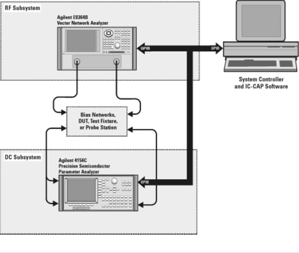
In conjunction with a compatible controller running 85190- Series IC- CAP
software, the Agilent 85225F performance modeling system measures the
DC and RF performance of active and passive devices. The IC- CAP
software then extracts the device parameters and displays the results.
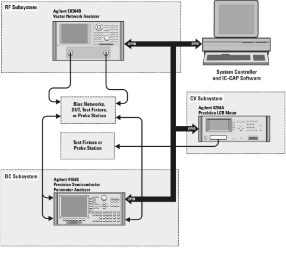
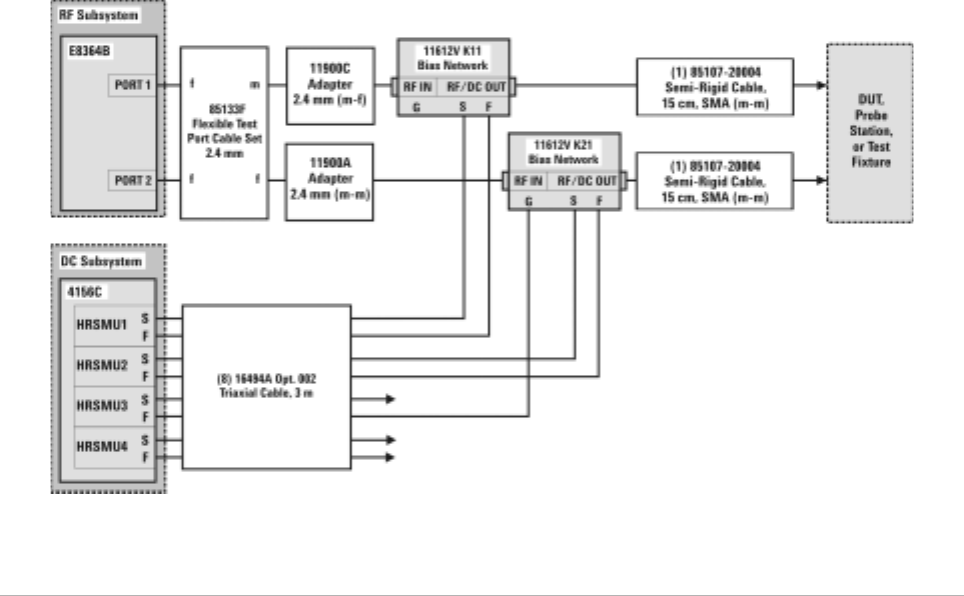
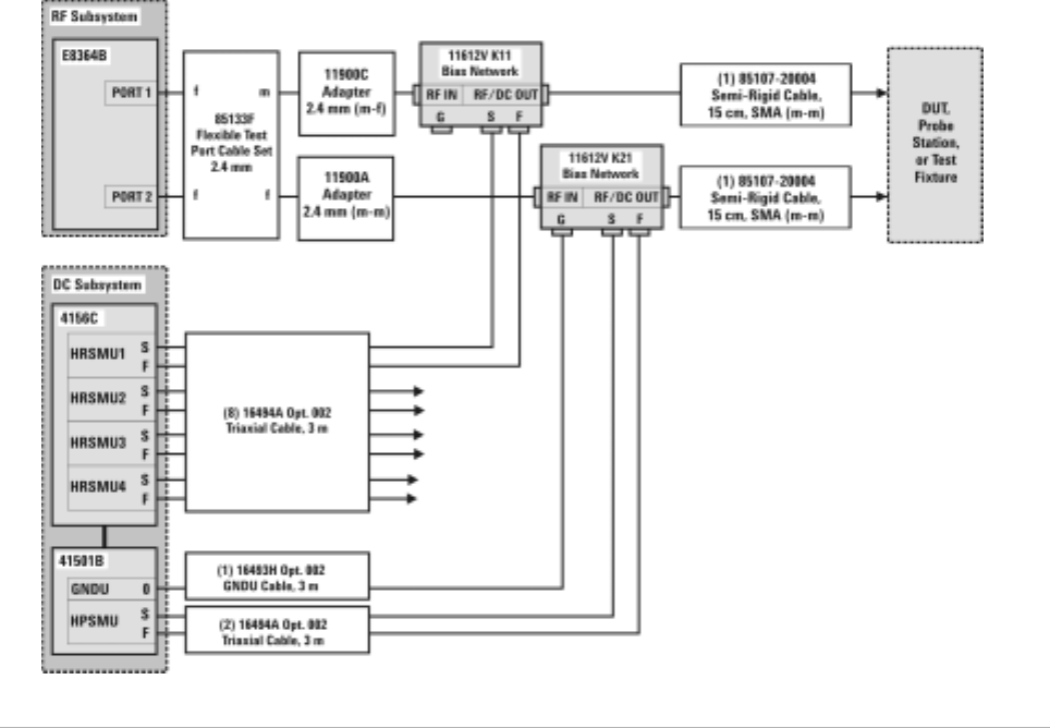
The Agilent 85225F performance modeling system is the integration of
rack- mounted RF and DC subsystems, bias networks, and a system
controller*, as shown in Figure 1†.
* The system controller is not included and must be provided.
† This block diagram shows a system with an Agilent 4156C as the DC subsystem. Other instrumentation may
be used. See “The DC Subsystem" on page 20.
Figure 1 System Block Diagram
20 Installation and User’s Guide
1Introducing the Agilent 85225F Performance Modeling System
The RF Subsystem
S- parameter device characterization is provided by the RF subsystem.
The RF subsystem contains the Agilent E8364B PNA Series vector network
analyzer.
Its integrated synthesizer supplies a swept or CW RF source signal from
10 MHz* to 50 GHz.
The integrated test set separates the RF source signal into reference and
test signals, and provides RF connection via cables and adapters to the
external bias networks.
The DC Subsystem
Precision DC characterization and bias for the S- parameter measurements
are provided by one of the following three DC subsystems.
The DC subsystem may contain one of the following three instruments.
Agilent 4156C Precision Semiconductor Parameter Analyzer
The Agilent 4156C precision semiconductor parameter analyzer provides
DC force (supply) and sense (measure) capability from its HRSMUs (high
resolution source/monitor units).
Optionally, the Agilent 4156C may be configured with a 41501B SMU PGU
expander is connected to and controlled by the 4156C via the expander
box interface. The 41501B provides a GNDU (active ground unit) and,
depending on option configuration, an HPSMU (high- power source/monitor
unit), two MPSMUs (medium- power source monitor units), and/or two
PGUs (pulse generator units).
The DC signals are routed through feedthrough panels via triaxial cables to
the bias networks.
Agilent E5260A 8-Slot High Speed Parametric Measurement Mainframe
The Agilent E5260A provides DC force (supply) and sense (measure)
capability from its plug- in source/monitor units.
The Agilent E5290A plug- in high speed high power source/monitor unit
provides up to 200 volts of potential and 1 amp of current to the device
under test.
The Agilent E5291A plug- in high speed medium power source/monitor unit
provides up to 100 volts of potential and 200 milliamps of current to the
device under test.
* Due to the minimum operating frequency of the bias networks, the performance modeling system low end
frequency range is 45 MHz.

Introducing the Agilent 85225F Performance Modeling System 1
Installation and User’s Guide 21
Agilent E5270B 8-Slot Precision Parametric Measurement Mainframe
The Agilent E5270B provides DC force (supply) and sense (measure)
capability from its plug- in source/monitor units.
The Agilent E5280A plug- in high power source/monitor unit provides up
to 200 volts of potential and 1 amp of current to the device under test.
The Agilent E5281A plug- in medium power source/monitor unit provides
up to 100 volts of potential and 200 milliamps of current to the device
under test.
The Bias Networks
The Agilent 11612V Option K11 and K21 bias networks combine the DC
and RF signals and apply them simultaneously to the device under test
(DUT). The bias networks are configured with 2.4 mm DC/RF output
connectors for connection to a DUT, a test fixture, or probe station, as
shown in Figure 21 on page 54.
CAUTION Exposing the bias networks to currents greater than 500 milliamps or voltages
greater than 40 volts will result in severe damage. Do not exceed these values
while using the bias networks. Remove the bias networks from the circuit if
greater voltages or currents are required.
22 Installation and User’s Guide
1Introducing the Agilent 85225F Performance Modeling System
Component Integration
System component integration is performed at the Agilent Technologies
factory. The individual components are placed into the rack, and the
required cabling is connected between the instruments.
After factory integration, the system is tested to verify functional
performance.
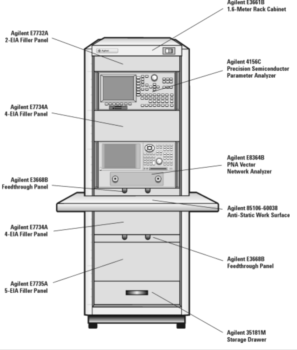
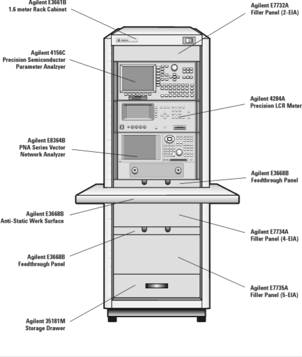
The Agilent 85225F performance modeling system includes the following
components, as shown in Figure 2 on page 23:
•Agilent E8364B PNA Series vector network analyzer
•Agilent 4156C precision semiconductor parameter analyzer (or
optionally Agilent E5260A or E5270B)
•Agilent 11612V Option K11 bias network (port 1)
•Agilent 11612V Option K21 bias network (port 2)
•Agilent 85133F flexible test port cable set
•Agilent E3661B 1.6 meter rack cabinet
•filler panels, feedthrough panels, work surface, cables, and adapters
For systems with Agilent 4156C, front panel connections are listed in
Table 3 on page 24 and illustrated in Figure 3 on page 25.
For systems with Agilent 4156C, rear panel connections are listed in
Table 5 on page 28 and illustrated in Figure 5 on page 29.
For systems with Agilent E5260A or E5270B, front panel connections are
listed in Table 4 on page 26 and illustrated in Figure 4 on page 27.
For systems with Agilent E5260A or E5270B, rear panel connections are
listed in Table 6 on page 30 and illustrated in Figure 6 on page 31.
Introducing the Agilent 85225F Performance Modeling System 1
Installation and User’s Guide 23
Figure 2 System Components

24 Installation and User’s Guide
1Introducing the Agilent 85225F Performance Modeling System
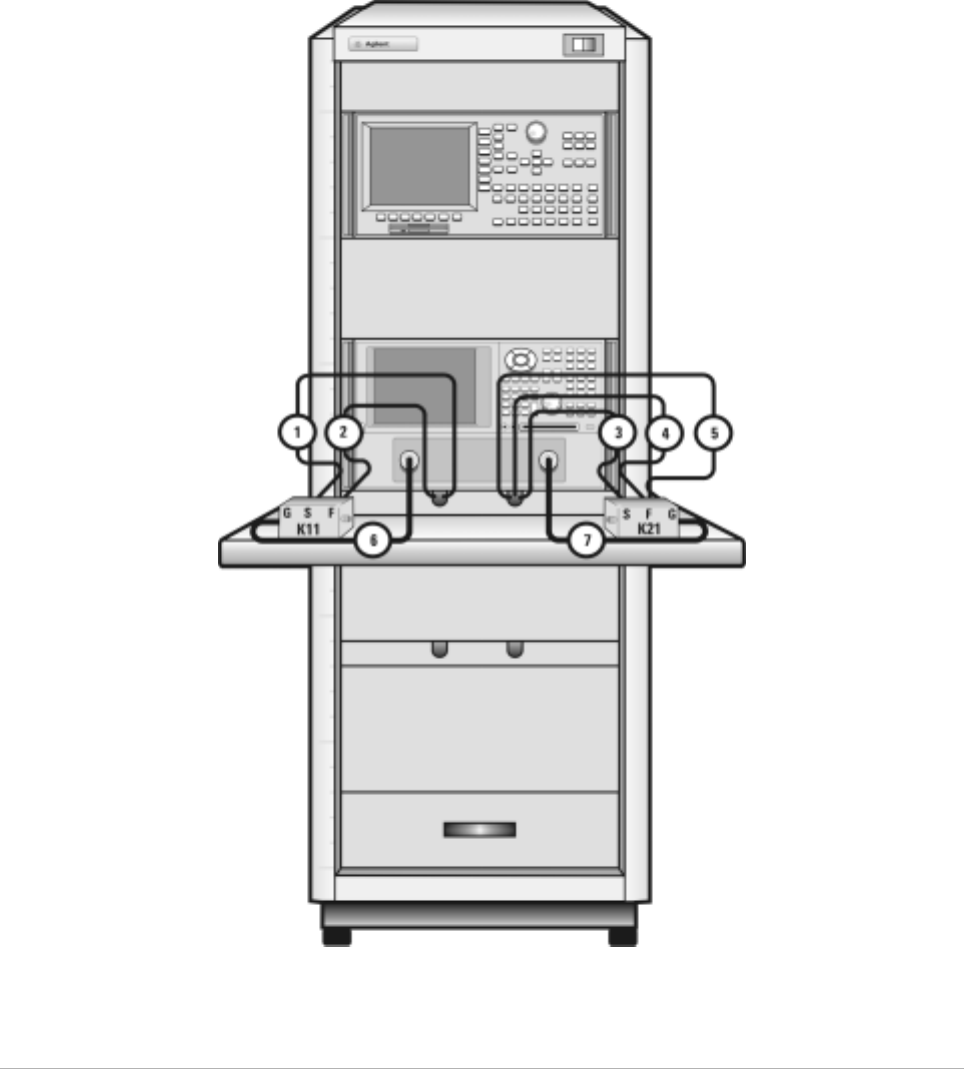
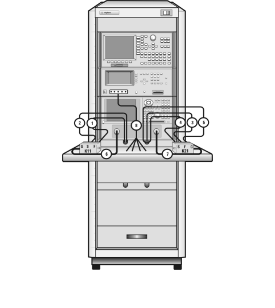
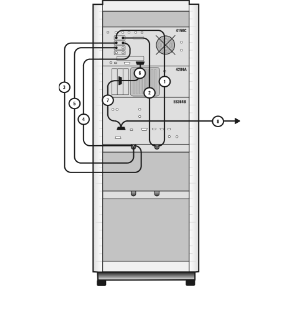
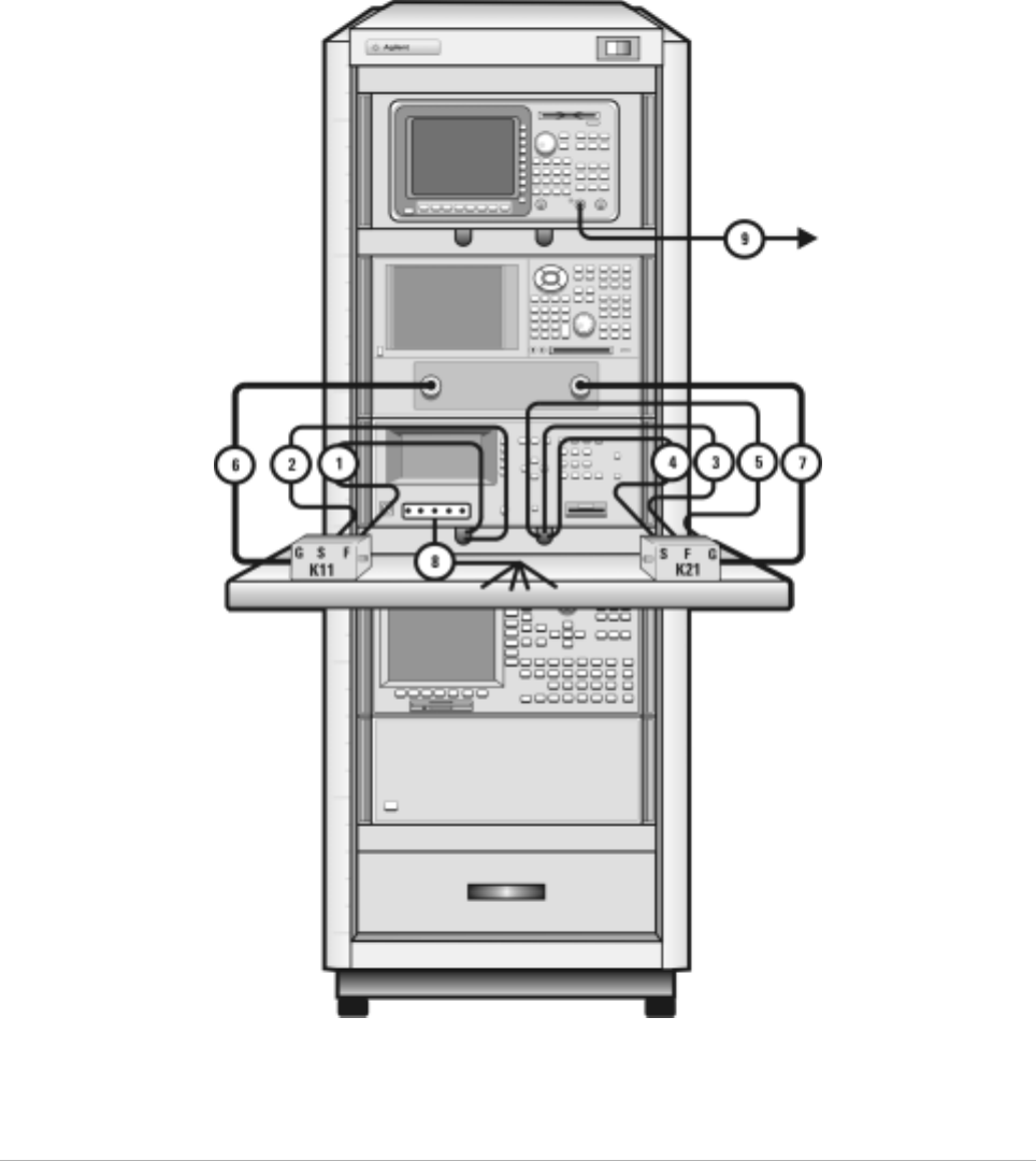
Table 3 Front Panel System Connections, with Agilent 4156C
Component Information Connection Information
Designator Model
Number Description Connector
Type From
Instrument Connector
Labeled To Connector
Labeled On
Instrument
1 16494A
Option 002 Triaxial cable Triax BNC 4156C
HRSMU1 SENSE DC SENSE 11612V K11
2 16494A
Option 002 Triaxial cable Triax BNC 4156C
HRSMU1 FORCE DC FORCE 11612V K11
3 16494A
Option 002 Triaxial cable Triax BNC 4156C
HRSMU2 SENSE DC SENSE 11612V K21
4 16494A
Option 002 Triaxial cable Triax BNC 4156C
HRSMU2 FORCE DC FORCE 11612V K21
5 16494A
Option 002 Triaxial cable Triax BNC 4156C
HRSMU3 FORCE GNDU 11612V K21
6 85133F Flexible test
port cable 2.4 mm E8364B PORT 1 RF IN 11612V K11
7 85133F Flexible test
port cable 2.4 mm E8364B PORT 2 RF IN 11612V K21
Introducing the Agilent 85225F Performance Modeling System 1
Installation and User’s Guide 25
Figure 3 Front Panel Connections with Agilent 4156C

26 Installation and User’s Guide
1Introducing the Agilent 85225F Performance Modeling System
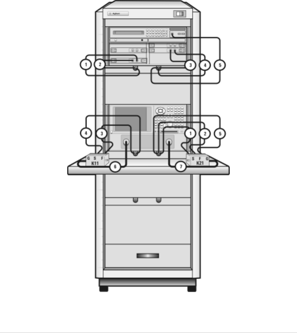
Table 4 Front Panel System Connections, with Agilent E5260A or E5270B
Component Information Connection Information
Designator Model
Number Description Connector
Type From
Instrument Connector
Labeled To C onn ecto r
Labeled On
Instrument
1 16494A
Option 002 Triaxial cable Triax BNC E5260A/70B
HPSMU1 SENSE DC SENSE 11612V K21
2 16494A
Option 002 Triaxial cable Triax BNC E5260A/70B
HPSMU1 FORCE DC FORCE 11612V K21
3 16494A
Option 002 Triaxial cable Triax BNC E5260A/70B
MPSMU3 FORCE DC FORCE 11612V K11
4 16494A
Option 002 Triaxial cable Triax BNC E5260A/70B
MPSMU3 SENSE DC SENSE 11612V K11
5 16493L
Option 002 Triaxial
GNDU cable Triax BNC E5260A/70B
GNDU GNDU GNDU 11612V K21
6 85133F Flexible test
port cable 2.4 mm E8364B PORT 1 RF IN 11612V K11
7 85133F Flexible test
port cable 2.4 mm E8364B PORT 2 RF IN 11612V K21
Introducing the Agilent 85225F Performance Modeling System 1
Installation and User’s Guide 27
Figure 4 Front Panel Wiring Diagram with Agilent E5260A or E5270B

28 Installation and User’s Guide
1Introducing the Agilent 85225F Performance Modeling System
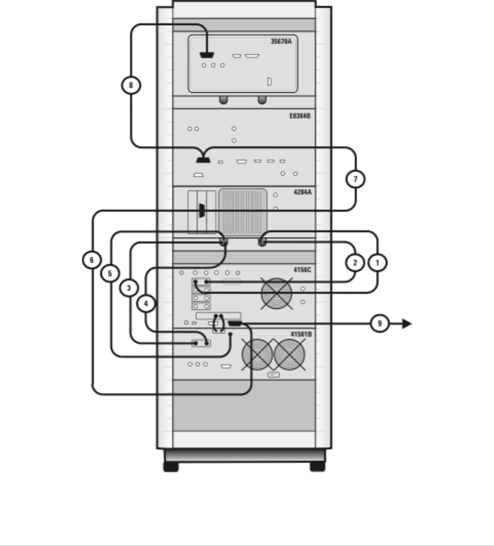
Table 5 Rear Panel System Connections with Agilent 4156C
Component Information Connection Information
Designator Model
Number Description Connector
Type From
Instrument Connector
Labeled To Connector
Labeled On
Instrument
1 16494A
Option 002 Triaxial cable Triax BNC 4156C
HRSMU2 FORCE DC FORCE 11612V K21
2 16494A
Option 002 Triaxial cable Triax BNC 4156C
HRSMU2 SENSE DC SENSE 11612V K21
3 16494A
Option 002 Triaxial cable Triax BNC 4156C
HRSMU1 FORCE DC FORCE 11612V K11
4 16494A
Option 002 Triaxial cable Triax BNC 4156C
HRSMU1 SENSE DC SENSE 11612V K11
5 16494A
Option 002 Triaxial cable Triax BNC 4156C
HRSMU3 FORCE GNDU 11612V K21
6 10833D GPIB cable GPIB 4156C GPIB GPIB E8364B
7 10833C GPIB cable GPIB E8364B GPIB GPIB Controller
NOTE If the system does not include an Agilent 41501B SMU/PGU expander,
use the Agilent 4156C HRSMU3 FORCE as the GND (ground unit).
Introducing the Agilent 85225F Performance Modeling System 1
Installation and User’s Guide 29
Figure 5 Rear Panel Wiring Diagram with Agilent 4156C

30 Installation and User’s Guide
1Introducing the Agilent 85225F Performance Modeling System
CV, RF, and DC M easure ment Sys tem C onfigu ration
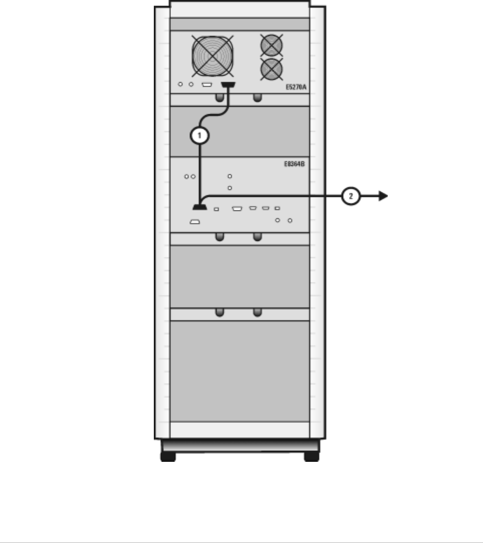
Table 6 Rear Panel System Connections with Agilent E5260A or E5270B
Component Information Connection Information
Designator Model
Number Description Connector
Type From
Instrument Connector
Labeled To C onn ecto r
Labeled On
Instrument
1 10833A GPIB cable GPIB 4156C GPIB GPIB E8364B
2 10833C GPIB cable GPIB E8364B GPIB GPIB Controller
Introducing the Agilent 85225F Performance Modeling System 1
Installation and User’s Guide 31
Figure 6 Rear Panel Wiring with Agilent E5260A or E5270B
32 Installation and User’s Guide
1Introducing the Agilent 85225F Performance Modeling System
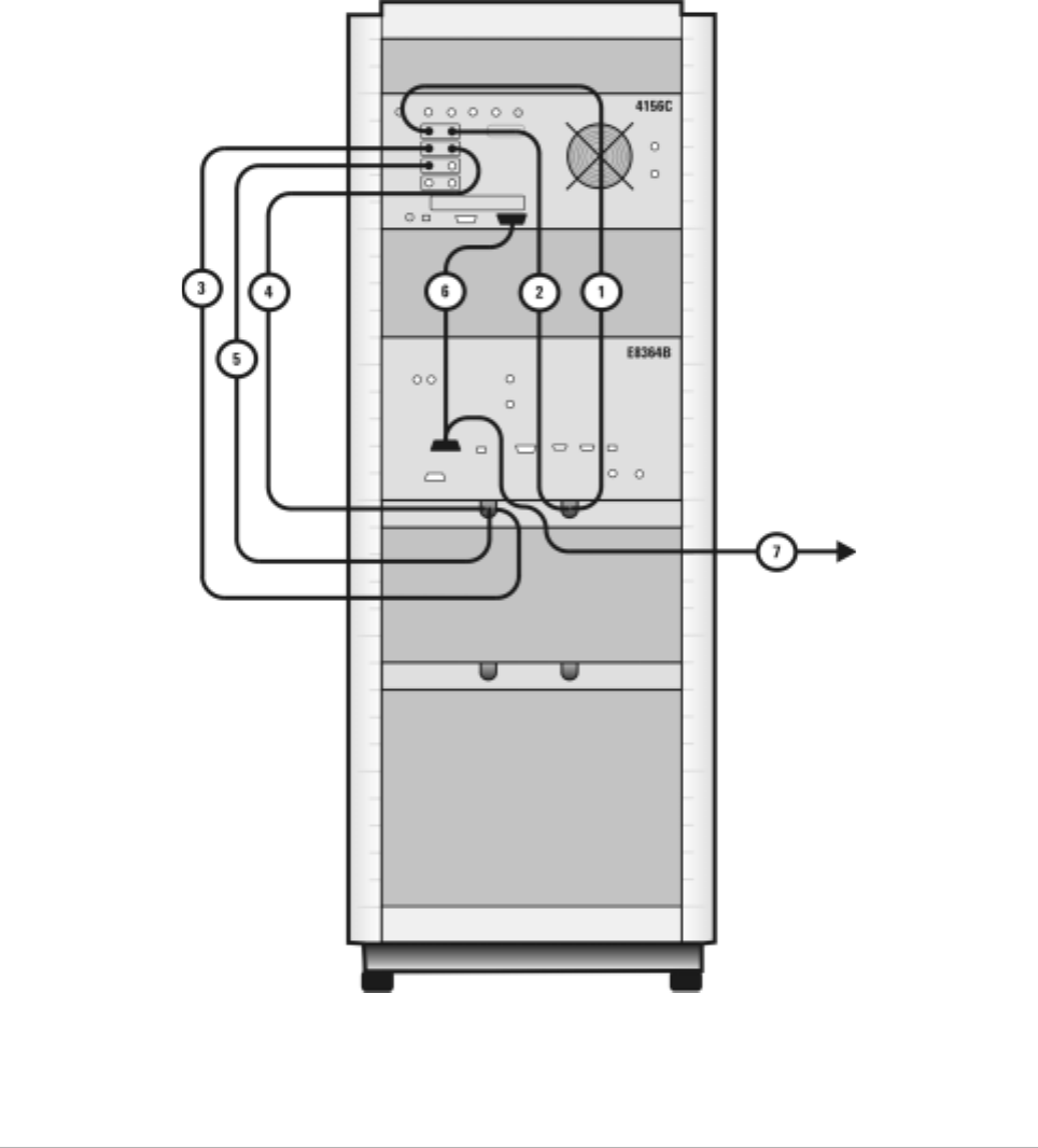
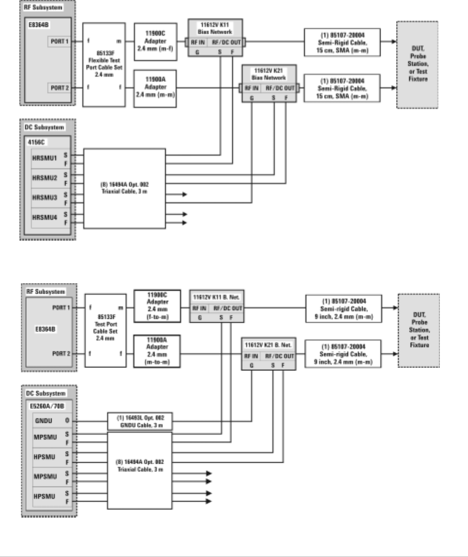
Figure 7 DC/RF Cabling Diagram - DC and RF Configuration
Systems with Agilent 4156C
Systems with Agilent E5260A or E5270B
Introducing the Agilent 85225F Performance Modeling System 1
Installation and User’s Guide 33
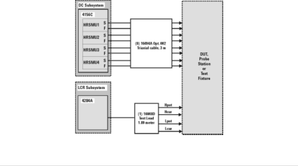
CV, RF, and DC Measurement System Configuration
With the addition of a precision LCR meter, the Agilent 85225F
performance modeling system measures the DC, RF, and CV performance
of active and passive devices. The IC- CAP software then extracts the
device parameters and displays the results.
The Agilent 85225F performance modeling system for CV, RF, and DC
measurement is the integration of rack- mounted RF, DC, and CV
subsystems, bias networks, and a system controller, as shown in Figure 8.
Figure 8 System Block Diagram
34 Installation and User’s Guide
1Introducing the Agilent 85225F Performance Modeling System
The CV Subsystem
The Agilent 4284A precision LCR meter provides a wide 20 Hz to 1 MHz
test frequency range and superior test- signal performance, allowing CV
testing to the most commonly- used test standards, such as IEC/MIL, and
under conditions that simulate the intended application.
Optionally, the system can be configured with the Agilent E5250A low
leakage switch mainframe. The Agilent E5250A is used for precise
parametric test. It improves measurement efficiency by eliminating the
need to manually change the probe positions on a manual probe station.
The E5250A is used to route signals from the DC and CV subsystems to
the probe card cable, and on to the probe card and probe station.
Component Integration
System component integration is performed at the Agilent Technologies
factory. The individual components are placed into the rack, and the
required cabling is connected between the instruments.
After factory integration, the system is tested to verify functional
performance.
The Agilent 85225F performance modeling system includes the following
components, as shown in Figure 18 on page 49:
•Agilent E8364B PNA Series vector network analyzer
•Agilent 4156C precision semiconductor parameter analyzer (or
optionally Agilent E5260A or E5270B)
•Agilent 11612V Option K11 bias network (port 1)
•Agilent 11612V Option K21 bias network (port 2)
•Agilent 4284A precision LCR meter
•Agilent 85133F flexible test port cable set
•Agilent E3661B 1.6 meter rack cabinet
•filler panels, feedthrough panels, work surface, cables, and adapters
System front panel connections are listed in Table 10 on page 50 and
illustrated in Figure 19 on page 51.
System rear panel connections are listed in Table 11 on page 52 and
illustrated in Figure 20 on page 53.
Introducing the Agilent 85225F Performance Modeling System 1
Installation and User’s Guide 35
Figure 9 System Components

36 Installation and User’s Guide
1Introducing the Agilent 85225F Performance Modeling System
Table 7 Front Panel System Connections
Component Information Connection Information
Designator Model
Number Description Connector
Type From
Instrument Connector
Labeled To Connector
Labeled On
Instrument
1 16494A
Option 002 Triaxial cable Triax BNC 4156C
HRSMU1 FORCE DC FORCE 11612V K11
2 16494A
Option 002 Triaxial cable Triax BNC 4156C
HRSMU1 SENSE DC SENSE 11612V K11
3 16494A
Option 002 Triaxial cable Triax BNC 4156C
HRSMU2 FORCE DC FORCE 11612V K21
4 16494A
Option 002 Triaxial cable Triax BNC 4156C
HRSMU2 SENSE DC SENSE 11612V K21
5 16494A
Option 002 Triaxial
GNDU cable Triax BNC 4156C
HRSMU3 FORCE GNDU 11612V K21
6 85133F Flexible test
port cable 2.4 mm E8364B PORT 1 RF IN 11612V K11
7 85133F Flexible test
port cable 2.4 mm E8364B PORT 2 RF IN 11612V K21
8 16048D LCR meter
test cable BNC 4284A UNKNOWN Test fixture
or probe
station
Introducing the Agilent 85225F Performance Modeling System 1
Installation and User’s Guide 37
Figure 10 Front Panel Wiring Diagram

38 Installation and User’s Guide
1Introducing the Agilent 85225F Performance Modeling System
Table 8 Rear Panel System Connections
Component Information Connection Information
Designator Model
Number Description Connector
Type From
Instrument Connector
Labeled To C onn ecto r
Labeled On
Instrument
1 16494A
Option 002 Triaxial cable Triax BNC 4156C
HRSMU1 FORCE DC FORCE 11612V K11
2 16494A
Option 002 Triaxial cable Triax BNC 4156C
HRSMU1 SENSE DC SENSE 11612V K11
3 16494A
Option 002 Triaxial cable Triax BNC 4156C
HRSMU2 FORCE DC FORCE 11612V K21
4 16494A
Option 002 Triaxial cable Triax BNC 4156C
HRSMU2 SENSE DC SENSE 11612V K21
5 16494A
Option 002 Triaxial cable Triax BNC 4156C
HRSMU3 FORCE GNDU 11612V K21
6 10833D GPIB cable GPIB 4156C GPIB GPIB 4284A
7 10833D GPIB cable GPIB 4284A GPIB GPIB E8364B
8 10833C GPIB cable GPIB E8364B GPIB GPIB Controller
Introducing the Agilent 85225F Performance Modeling System 1
Installation and User’s Guide 39
Figure 11 Rear Panel Wiring Diagram
40 Installation and User’s Guide
1Introducing the Agilent 85225F Performance Modeling System
Figure 12 DC/RF Cabling Diagram - DC and RF Configuration
Introducing the Agilent 85225F Performance Modeling System 1
Installation and User’s Guide 41
Figure 13 DC/RF Cabling Diagram - Parametric Configuration

42 Installation and User’s Guide
1Introducing the Agilent 85225F Performance Modeling System
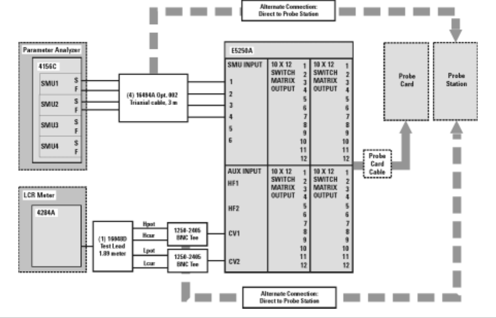
The Low Leakage Switch Mainframe
The Agilent E5250A is used for precise parametric test. It improves
measurement efficiency by eliminating the need to manually change the
probe positions on a manual probe station. The E5250A is used to route
signals from the 4156C and the 4284A to the probe card cable, and on to
probe card and probe station.
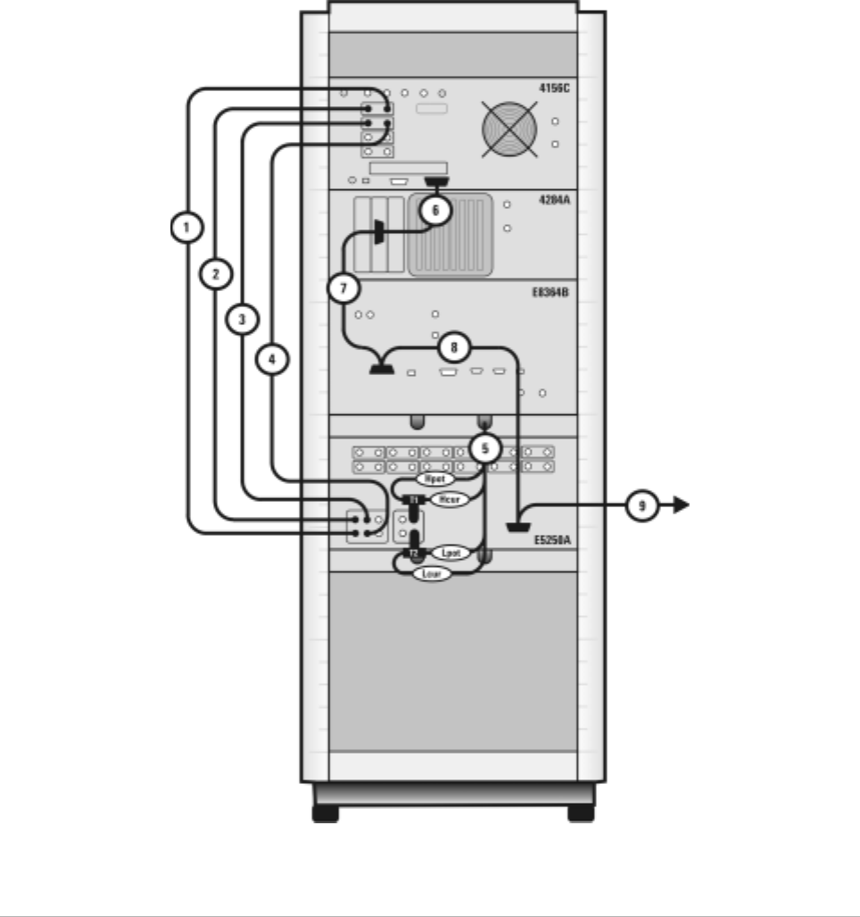
Table 9 Rear Panel Connections, including Low Leakage Switch Mainframe
Component Information Connection Information
Designator Model
Number Description Connector
Type From
Instrument Connector
Labeled To C onn ecto r
Labeled On
Instrument
1 16494A
Option 002 Triaxial cable Triax BNC 4156C
HRSMU1 SENSE SMU
INPUT 2 E5250A
2 16494A
Option 002 Triaxial cable Triax BNC 4156C
HRSMU1 FORCE SMU
INPUT 1 E5250A
3 16494A
Option 002 Triaxial cable Triax BNC 4156C
HRSMU2 FORCE SMU
INPUT 3 E5250A
4 16494A
Option 002 Triaxial cable Triax BNC 4156C
HRSMU2 SENSE SMU
INPUT 4 E5250A
5 16048D LCR meter
test cable BNC 4284A UNKNOWN T1 & T2 (CV1
& CV2) E5250A
6 10833D GPIB cable GPIB 4156C GPIB GPIB 4284A
7 10833D GPIB cable GPIB 4284A GPIB GPIB E8364B
8 10833D GPIB cable GPIB E8364B GPIB GPIB E5250A
9 10833C GPIB cable GPIB E5250A GPIB GPIB Controller
T1 1250-2405 BNC tee BNC 4284A HIpot/HIcur CV1 E5250A
T2 1250-2405 BNC tee BNC 4284A LOpot/LOcur CV2 E5250A
Introducing the Agilent 85225F Performance Modeling System 1
Installation and User’s Guide 43
Figure 14 Rear Panel Wiring Diagram including Low Leakage Switch Mainframe
44 Installation and User’s Guide
1Introducing the Agilent 85225F Performance Modeling System
Figure 15 DC/RF Cabling Diagram - Parametric Configuration with Low Leakage Switch Mainframe
Introducing the Agilent 85225F Performance Modeling System 1
Installation and User’s Guide 45
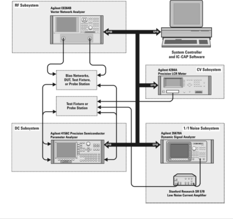
1/f Noise, CV, RF, and DC Measurement System Configuration
With the addition of a dynamic signal analyzer and a precision LCR meter,
the Agilent 85225F performance modeling system measures the DC, RF,
CV, and 1/f noise performance of active and passive devices. The IC- CAP
software then extracts the device parameters and displays the results.
The Agilent 85225F performance modeling system is the integration of
rack- mounted RF and DC subsystems, a precision LCR meter, a dynamic
signal analyzer, bias networks, and a system controller, as shown in
Figure 16.
46 Installation and User’s Guide
1Introducing the Agilent 85225F Performance Modeling System
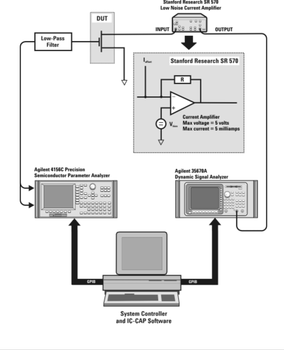
The 1/f Noise Subsystem
The Agilent 35670A dynamic signal analyzer (in conjunction with a
customer- furnished Stanford Model SR570 low noise amplifier) measures
the flicker noise (1/f noise) of active devices. Controlled by IC- CAP device
modeling software, the dynamic signal analyzer generates reliable 1/f noise
measurement data, which are analyzed and extracted in IC- CAP. Figure 17
shows the system configuration for 1/f noise measurements.
Figure 16 System Block Diagram
Introducing the Agilent 85225F Performance Modeling System 1
Installation and User’s Guide 47
Figure 17 1/f Noise Measurement Block Diagram
48 Installation and User’s Guide
1Introducing the Agilent 85225F Performance Modeling System
Component Integration
System component integration is performed at the Agilent Technologies
factory. The individual components are placed into the rack, and the
required cabling is connected between the instruments.
After factory integration, the system is tested to verify functional
performance.
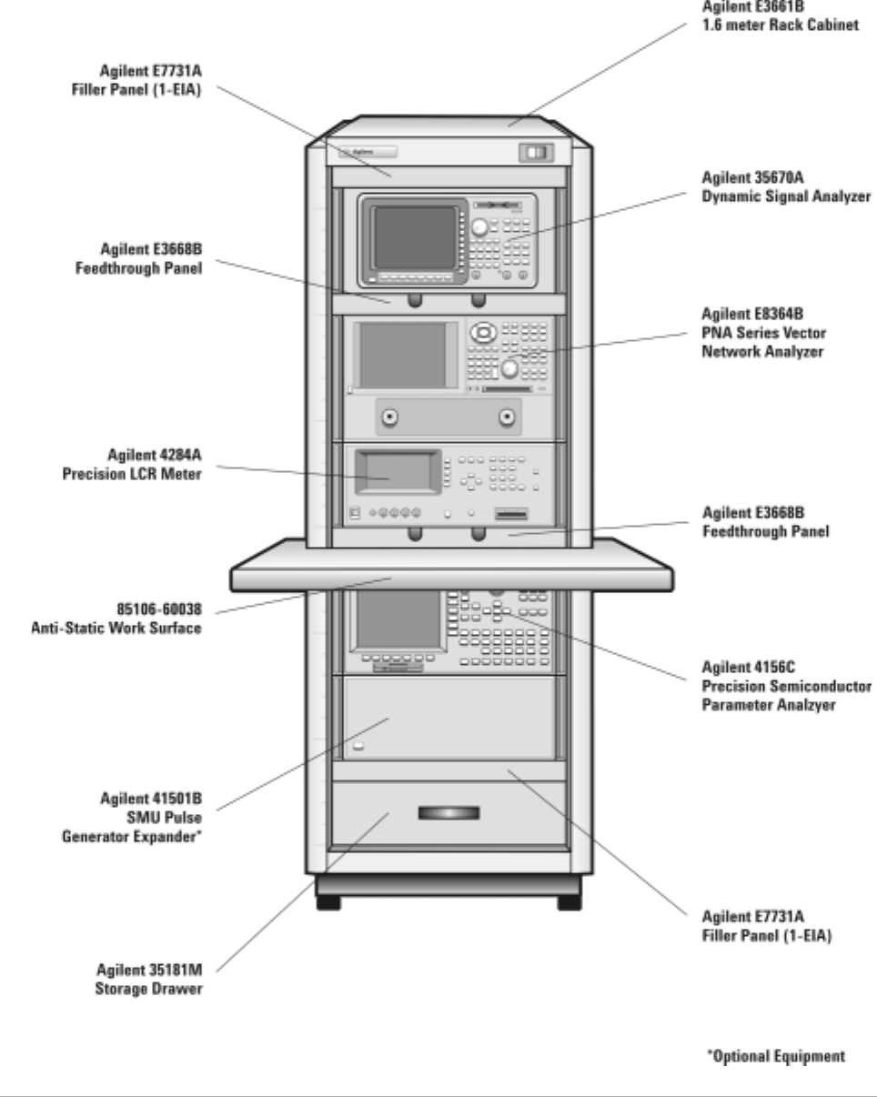
The Agilent 85225F performance modeling system includes the following
components, as shown in Figure 18 on page 49:
•Agilent E8364B PNA Series vector network analyzer
•Agilent 4156C precision semiconductor parameter analyzer with
optional Agilent 41501B SMU/PGU expander (or optionally Agilent
E5260A or E5270B)
•Agilent 11612V Option K11 bias network (port 1)
•Agilent 11612V Option K21 bias network (port 2)
•Agilent 4284A precision LCR meter
•Agilent 35670A dynamic signal analyzer
•Stanford Research SR 570 low noise current amplifier*
•Agilent 85133F flexible test port cable set
•Agilent E3661B 1.6 meter rack cabinet
•filler panels, feedthrough panels, work surface, cables, and adapters
System front panel connections are listed in Table 10 on page 50 and
illustrated in Figure 19 on page 51.
System rear panel connections are listed in Table 11 on page 52 and
illustrated in Figure 20 on page 53.
* Customer supplied, not included with system.
Introducing the Agilent 85225F Performance Modeling System 1
Installation and User’s Guide 49
Figure 18 System Components

50 Installation and User’s Guide
1Introducing the Agilent 85225F Performance Modeling System
Table 10 Front Panel System Connections
Component Information Connection Information
Designator Model
Number Description Connector
Type From
Instrument Connector
Labeled To Connector
Labeled On
Instrument
1 16494A
Option 002 Triaxial cable Triax BNC 41501B
HPSMU FORCE DC FORCE 11612V K11
2 16494A
Option 002 Triaxial cable Triax BNC 41501B
HPSMU SENSE DC SENSE 11612V K11
3 16494A
Option 002 Triaxial cable Triax BNC 4156C
HRSMU1 FORCE DC FORCE 11612V K21
4 16494A
Option 002 Triaxial cable Triax BNC 4156C
HRSMU1 SENSE DC SENSE 11612V K21
5 16493L
Option 002 Triaxial
GNDU cable Triax BNC 41501B GNDU GNDU 11612V K21
6 85133F Flexible test
port cable 2.4 mm E8364B PORT 1 RF IN 11612V K11
7 85133F Flexible test
port cable 2.4 mm E8364B PORT 2 RF IN 11612V K21
8 16048D LCR meter
test cable BNC 4284A UNKNOWN Test fixture
or probe
station
9 8120-1839 Coaxial cable BNC 35670A CH1 Test fixture
or probe
station
Introducing the Agilent 85225F Performance Modeling System 1
Installation and User’s Guide 51
Figure 19 Front Panel Wiring Diagram

52 Installation and User’s Guide
1Introducing the Agilent 85225F Performance Modeling System
Table 11 Rear Panel System Connections
Component Information Connection Information
Designator Model
Number Description Connector
Type From
Instrument Connector
Labeled To Connector
Labeled On
Instrument
1 16494A
Option 002 Triaxial cable Triax BNC 4156C
HRSMU1 FORCE DC FORCE 11612V K11
2 16494A
Option 002 Triaxial cable Triax BNC 4156C
HRSMU1 SENSE DC SENSE 11612V K11
3 16494A
Option 002 Triaxial cable Triax BNC 41501B
HPSMU FORCE DC FORCE 11612V K21
4 16494A
Option 002 Triaxial cable Triax BNC 41501B
HPSMU SENSE DC SENSE 11612V K21
5 16493L
Option 002 GNDU cable Triax BNC 41501B GNDU GNDU 11612V K21
6 10833A GPIB cable GPIB 4156C GPIB GPIB 4284A
7 10833A GPIB cable GPIB 4284A GPIB GPIB E8364B
8 10833A GPIB cable GPIB E8364B GPIB GPIB 35670A
9 10833C GPIB cable GPIB 4156C GPIB GPIB Controller
Introducing the Agilent 85225F Performance Modeling System 1
Installation and User’s Guide 53
Figure 20 Rear Panel Wiring Diagram
54 Installation and User’s Guide
1Introducing the Agilent 85225F Performance Modeling System
Figure 21 DC/RF Cabling Diagram - DC and RF Configuration

Introducing the Agilent 85225F Performance Modeling System 1
Installation and User’s Guide 55
Figure 22 DC/RF Cabling Diagram - Parametric Configuration

56 Installation and User’s Guide
1Introducing the Agilent 85225F Performance Modeling System
Instrument Control Interface
Instrument control interface is provided by a General Purpose Interface
Bus (GPIB) or LAN/GPIB gateway. GPIB addresses for programmable
system components are listed in Table 12.
Table 12 GPIB Addresses
Component GPIB Address
Agilent 34401A digital multimeter 9
Agilent 35670A dynamic signal analyzer 10
Agilent 4156C precision semiconductor parameter analyzer 19*
* The 4156C default GPIB address 17 is sometimes used by other devices with a GPIB address at 16 (for example, an external display (set
to 17) to display the results generated by an instrument at address 16). Change the 4156C GPIB address to 19 using the procedure
described in step 13 of “To switch on power to the system" on page 87 to ensure that IC-CAP can recognize the 4156C.
Agilent 4284A precision LCR meter 24
Agilent E5810A LAN/GPIB gateway 21
Agilent E8364B PNA Series vector network analyzer 16
Agilent E5250A low leakage switch mainframe 22
Agilent E5260A 8-slot high speed parametric measurement mainframe 19
Agilent E5270B 8-slot precision parametric measurement mainframe 19
Introducing the Agilent 85225F Performance Modeling System 1
Installation and User’s Guide 57
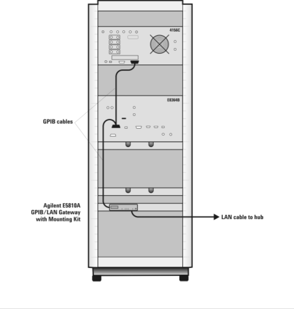
The LAN/GPIB Gateway
The Agilent E5810A LAN/GPIB gateway provides access to the system’s
GPIB instrumentation over an existing local area network. It allows the
use of SICL- or VISA- based applications designed for GPIB over the LAN
without modifying the application beyond a simple address change.
The gateway is a combination of hardware and SICL/VISA software. It
uses client/server technology to extend the standard remotely over the
LAN, allowing remote control from an alternative, more convenient, or
safer location.
58 Installation and User’s Guide
1Introducing the Agilent 85225F Performance Modeling System
Figure 23 Rear Panel Wiring Diagram for LAN/GPIB Gateway

Introducing the Agilent 85225F Performance Modeling System 1
Installation and User’s Guide 59
The System Controller
A customer- furnished UNIX workstation or personal computer running
Agilent IC- CAP software controls the hardware via GPIB while making
device measurements, then stores, simulates, and optimizes device
parameters, using predefined or user- defined device models. Table 13 on
page 59 lists the personal computer requirements. Table 14 on page 59
lists the UNIX workstation requirements.
Table 13 Personal Computer Requirements
Parameter Requirement
Operating system Microsoft Windows NT® 4.0-SP6a or Windows 2000 Professional-SP3.*
* Windows 95, 98, and ME are not supported.
CPU Intel Pentium® class 200 MHz CPU or higher
Display Super VGA 800×600, 15 inch monitor (1024×728 recommended)
Hard disk space 370 MB. It is recommended that you install IC-CAP software on your local drive.
Recommended file systems are FAT32 and NTFS. Novell file servers are not
supported. VFAT/FAT systems are not recommended for full installations.
RAM 128 megabytes (additional RAM will improve software performance)
Virtual memory 300 megabytes† (Increased virtual memory may be required)
† For NT 4.0 only: to avoid potential memory problems, ensure your virtual memory space is always greater than your RAM space.
Table 14 UNIX Workstation Requirements
Parameter Requirement
HP UNIX Workstation SunOS Workstation
Operating system HP-UX 11.i with the following patches:
PHSS_24627 HP aC++, AA Runtime
Libraries (aCC A.03.33), PHSS_25718 LIBCL
SunOS 5.7, 5.8, and 5.9
(Solaris 7.0, 8.0, 9.0)
Window manager HP VUE or CDE/X-Windows V.X11R5 Motif V.1.1/1.2 Open Windows 3.0, or CDE
RAM 128 megabytes (additional RAM will improve software performance)
Swap space 200 megabytes (additional swap space will improve software performance)
Hard disk 300 megabytes for minimum installation
500 megabytes for complete installation including online documentation and application
examples
Display High resolution color only
60 Installation and User’s Guide
1Introducing the Agilent 85225F Performance Modeling System
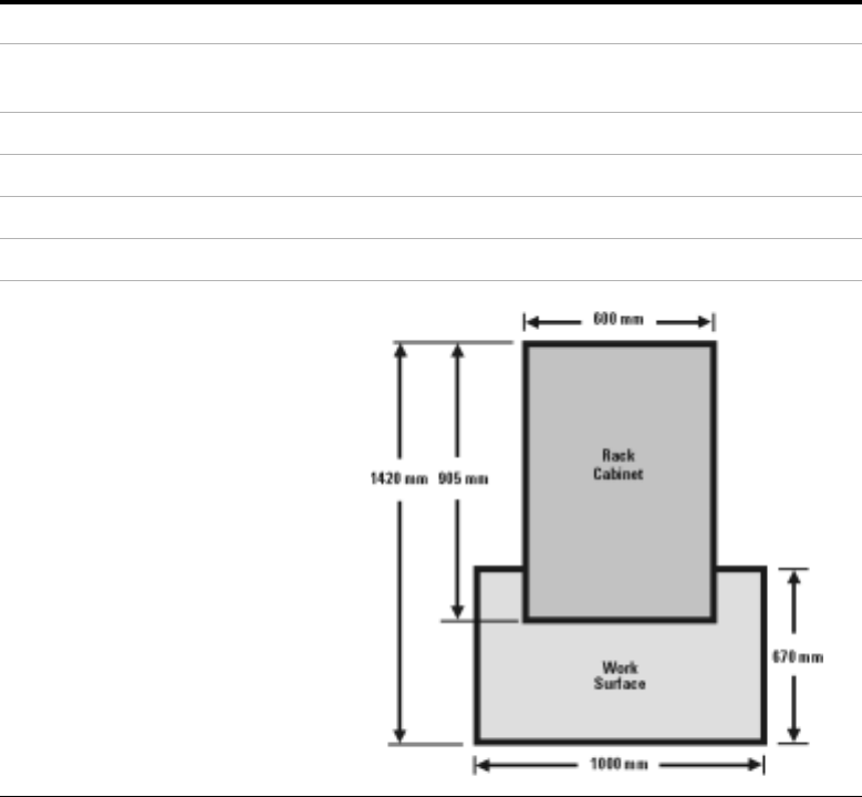
The Rack Cabinet
The system is housed in a 1.6 meter rack cabinet. The cabinet provides
line power access, ventilation, mobility, and protection to the system
instrumentation.
A rack- mounted work surface is included for maximum flexibility and
convenience in making in- fixture or coaxial measurements. The work
surface can be removed to facilitate on- wafer measurements using a probe
station. The work surface is coated with antistatic material and connected
to chassis ground. Therefore, an antistatic mat is not required. For
installation instructions, see “To install the work surface" on page 74.
Introducing the Agilent 85225F Performance Modeling System 1
Installation and User’s Guide 61
Performance Characteristics and Specifications
Supplemental characteristics are not specifications, but are provided in
Table 15 for your convenience.
Interference Standards
The IEC/EN 61326- 1 and CISPR Publication 11 standards define the RFI
and EMI susceptibility of the performance modeling system.
Performance Modeling System Performance Specifications
The Agilent 85225F performance modeling system adheres to the
performance specifications of an Agilent E8364B PNA Series vector
network analyzer. Refer to Appendix G, “Network Analyzer Performance
Specification Summary,” starting on page 141.
Table 15 Supplemental System Characteristics
Characteristic Value
Line voltage 115 volts nominal (90 volts to 132 volts) or 220 volts nominal
(210 volts to 250 volts)
Line frequency 48 Hz to 66 Hz
Circuit breaker amperage rating 6 amps (115 volts), 3.5 amps (220 volts)
Rack weight capacity 818 kilograms (1800 pounds) maximum loaded
Rack external dimensions 1620 mm high × 600 mm wide × 905 mm deep
Rack footprint (top view)

62 Installation and User’s Guide
1Introducing the Agilent 85225F Performance Modeling System
RF Subsystem Performance Specifications
The overall performance of a network analyzer is dependent on the
individual instruments, system configuration, user- defined operating
conditions, measurement calibration, and cables.
For a specification summary, refer to Appendix G, “Network Analyzer
Performance Specification Summary,” starting on page 141.
In any high- frequency measurement, residual errors contribute
uncertainties to the results.
DC Subsystem Specifications
Specifications for the Agilent 4156C precision semiconductor parameter
analyzer are listed in its user’s guide, chapter 7 of Volume 1, “General
Information.”
Specifications for the Agilent E5260A 8- slot high speed measurement
mainframe and Agilent E5270B 8- slot precision parametric measurement
mainframe are listed in its user’s guide, Chapter 2, “Introduction.”
Bias Network Characteristics
Table 20, “11612V Option K11/K21 Bias Network Characteristics,” on
page 139 lists the operational characteristics of the bias networks. For
detailed information, refer to Appendix F, “Understanding the Bias
Networks,” starting on page 137.
NOTE When the system is configured with a probe station, microwave probes, on-wafer
calibration standards, or test fixtures, additional uncertainties are contributed to the
measurement results. Refer to the manufacturer’s documentation for information on probe
station or test fixture characteristics.

63
Agilent 85225F Performance Modeling System
Installation and User’s Guide
Agilent Technologies
2
Installing the System
To prepare the installation site 64
Environmental Requirements 64
Electrical Requirements 64
To receive the system 65
To unpack the shipment crate containing the rack cabinet 66
To verify the shipment 68
To install the work surface 74
To ensure your safety while using the system 76
Precautions for Performing Floating-Ground Measurements 78
Precautions for Avoiding Electrostatic Discharge 79
To connect the bias networks 80
To switch on power to the system 87
This completes the installation process. To confirm the functionality of the
system, continue to Chapter 3, “Verifying System Functionality,”
starting on page 91. 89
Related Topics “Introducing the Agilent 85225F Performance Modeling System" on
page 17
Use this chapter to learn how to first prepare the installation site, and
then receive, unpack, install, and configure the system. This chapter
includes important information on operational safety, as well as
instruction on preparing the installation site, unpacking the system,
ensuring the completeness of the system shipment, installing the work
surface, performing final system configuration, and powering- on the
system.

64 Installation and User’s Guide
2Installing the System
To prepare the installation site
Follow these steps to prepare the site for system installation.
CAUTION This product is designed for indoor use in Installation Category II
and Pollution Degree 2 per IEC 61010-1 and 664 respectively.
To prepare the installation site
Step Notes
1Ensure that your installation site meets the
environmental requirements. •Environmental requirements (temperature,
relative humidity, altitude, and clearance) are
listed in Table 16.
2Ensure that your installation site meets the
electrical requirements. •Electrical requirements are listed in Table 17.
Table 16 Environmental Requirements
Environmental Parameter System Requirement
Temperature +0°C to +45°C (+32°F to +113°F)*†
* Install air conditioning and heating as needed to achieve the required ambient temperature range.
† Accuracy-enhanced measurement performance is specified at an ambient temperature range of
+25°C ±5°C. After calibration, hold the ambient temperature of the measurement environment to
±1°C of the ambient temperature at the time of calibration.
Relative humidity Maximum 80% for temperatures up to 31°C
decreasing linearly to 50% at 40°C
Altitude Up to 3000 meters (approximately 10000 feet)
Clearance (behind and above rack)‡
‡ Required to ensure the extractor fans can properly ventilate the system.
15 centimeters (6 inches) minimum
Table 17 Electrical Requirements
Electrical Parameter System Requirement
Supply capability 100/120 volts, 2000 VA
200/240 volts, 2000 VA
Circuit sharing Do not connect air conditioning or
motor-operated equipment to the same ac
circuit supplying line voltage to the system.

Installing the System 2
Installation and User’s Guide 65
To receive the system
Follow these steps to store, inspect, and confirm the system shipment.
To receive the system
Step Action Notes
1Store and inspect the
shipment. aKeep the shipping containers together,
unopened, located in one area.
bInspect the shipping containers for
damage.
•If the shipment is damaged, continue to
step 2.
•If the shipment is verified undamaged,
continue to the next section, “To unpack
the shipment crate containing the rack
cabinet" on page 66.
•Keep all cartons and packaging
material until the entire shipment has
been verified undamaged and
complete, and the system has passed
visual inspection and functional
verification.
2If the system is damaged,
notify appropriate parties. aReport the shipment damage to your
Agilent Technologies sales representative.
bReport the shipment damage to the
shipping carrier.
cProvide all cartons and packaging material
for inspection by the shipping carrier.
•Agilent Technologies will repair or
replace damaged equipment without
waiting for a claim settlement from the
shipping carrier.

66 Installation and User’s Guide
2Installing the System
To unpack the shipment crate containing the rack cabinet
The racked system is shipped upright secured to a pallet. Other system
components are shipped separately. Follow these instructions to unpack
and inspect the rack cabinet and the racked system components.
Required Tools
•9/16 inch wrench or adjustable end wrench
•Prying tool to remove packaging clamps
WARNING Always wear safety glasses when removing the clamps and other
packing materials from the crate.
CAUTION Be careful not to bend the clamps while removing them from the
shipping crate. You may reuse the clamps when the system is
repacked.
To unpack the shipment crate containing the rack cabinet
Step Action Notes
1Remove the outer packing
crate. aRemove the clamps holding the packing
crate top cover in place.
bRemove the top cover and set it aside.
cRemove the clamps holding the first
packing crate wall in place.
dInsure that two other people are available
to hold the last two walls in place as the
last set of clamps is removed.
eRemove the other walls.
fSet the loading ramp panel aside for now.
•Which wall is removed first does not
matter.
•In double-rack crates, the heaviest wall
is the loading ramp. In single-rack
crates, the loading ramp is shipped
inside the crate, placed on top of the
rack (it is a hinged assembly, shipped in
the folded position).
2Remove the packaging
materials. aRemove the foam top cover.
bRemove the plastic wrapping from the
system.
Installing the System 2
Installation and User’s Guide 67
3Unload the system aRemove the two brace bolts attaching the
side brace assembly to the bottom pallet.
bRemove the side brace assembly.
cLift the hinged slat and remove the ramp
anchor bolt.
dPlace one end of the ramp on the pallet
ramp ledge.
eInsert the ramp anchor bolt and fold down
the hinged slat.
fFold down the ramp’s end flap.
•To secure the ramp, you may place long
wood screws through the ramp and
into the ramp ledge.
gEnsure that the rack cabinet leveling feet
are retracted and that the cabinet casters
are rolling freely.
hRoll the system down the ramp using
extreme care.
iCarefully roll the rack toward its prepared
place within the measurement
environment.
•In case the system must be moved in
the future, retain and reuse these
packing materials. You can also
purchase replacement packing
materials from Agilent Technologies.
To unpack the shipment crate containing the rack cabinet (continued)
Step Action Notes
WARNING A racked system is tall and top-heavy. It is easy to tip the rack
over while moving it, which could result in injury or death.
Unloading the system safely requires the participation of four
persons exercising care so as not to topple the rack cabinet. Do
not stand in front of the rack as it rolls down the ramp.

68 Installation and User’s Guide
2Installing the System
To verify the shipment
Use Table 18 “System Receiving Checklist and Replaceable Parts” to:
•confirm the completeness of the shipment
•provide component part and model numbers required to order
replacement parts
All replacement items are available from Agilent Technologies. Part
numbers for replacement instrument subassemblies are listed in their
individual service manuals.
The majority of the system components are shipped preconfigured in the
system rack cabinet.
The PGUs (pulse generator units) and GNDU (active ground unit) are
factory- installed in the 41501B PGU expander.
With the exception of the bias networks, semi- rigid and SMU triaxial
cables, all other cables are connected at the factory.
NOTE Other cables and accessories are shipped inside the rack-mounted storage drawer.
To verify the shipment
Step Action Notes
1Verify that the serial
numbers on the rear panel
of the system instruments
match the serial numbers
listed in the shipping
documentation.
Compare the serial numbers listed in the
shipping documents with the serial numbers
on the instrument’s rear panel serial number
labels.
•If an instrument serial number does not
match the shipping document, report
mismatched serial number to your
Agilent Technologies sales
representative.
•If all instrument serial numbers match
the shipping documents, continue to
step 2.
•For a list of support contacts, see “To
receive additional assistance" on
page 107.
Installing the System 2
Installation and User’s Guide 69
1
2Complete the receiving
checklist. aCompare the Bill of Materials to the system
components received in the shipment.
bVerify the shipment is complete.
•If the shipment is confirmed incomplete,
go to step 3.
•If you have confirmed the presence of all
system components, the receiving
process is complete. Proceed to the next
section “To ensure your safety while
using the system" on page 76.
•Refer to the Bill of Materials included
with the shipment.
3If the system is
incomplete, report
missing items to your
Agilent Technologies
sales representative.
•For a list of support contacts, see “To
receive additional assistance" on
page 107.
Table 18 Replaceable Parts
Part or Model Number Description
10833A GPIB cable, 1 meter
10833B GPIB cable, 2 meter
10833C GPIB cable, 4 meters
10833D GPIB cable, 0.5 meter
11612T Option K33 Mounting plates, bias networks to probe station
11612V Option K11 Bias network, port 1, 45 MHz to 50 GHz, 0.5 A
11612V Option K21 Bias network, port 2, 45 MHz to 50 GHz, 0.5 A
11900A Adapter, 2.4 mm (male-to-male)
11900B Adapter, 2.4 mm (female-to-female)
11900C Adapter, 2.4 mm (male-to-female)
1250-0080 Adapter, BNC, 50 ohm (female-female)
1250-1700 Adapter, coax
1250-2405C Adapter, BNC coaxial tee
1250-3231 Adapter, triaxial BNC (female to male)
16048D Test leads, 4 terminal pair, 1.98 meter
16493J Option 001 Interlock cable, 1.5 meter
16493L Option 001 GNDU cable, 1.5 meter
To verify the shipment (continued)
Step Action Notes

70 Installation and User’s Guide
2Installing the System
16494A Option 001 Triaxial cable, 1.5 meter
16494A Option 002 Triaxial cable, 3 meter
16494B Option 001 Kelvin triaxial cable, 1.5 meter
16494B Option 002 Kelvin triaxial cable, 3 meter
34401A Digital multimeter
35181M Storage drawer
35670A Dynamic signal analyzer
35670A Option AX4 Rack flange kit
35670A Option AY2 Two-input channel configuration
35670A Option AY6 Four-input channel configuration
35670A Option 1D4 Arbitrary source
41501B SMU/PGU expander with GNDU and cable
41501B Option 410 Add 41501B with high power SMU and cables
41501B Option 412 Add high power SMU, 2 PGUs, and cables
41501B Option 420 Add 2 medium power SMUs and cables
41501B Option 422 Add 2 medium power SMUs, 2 PGUs, and cables
41501B Option 902 Cable, power, Europe
41501B Option 903 Cable, power, US and Canada
4156C Precision semiconductor parameter analyzer
4156C Option 010 Delete all 4156C cables
4156C Option 020 Delete Windows controller for parameter analysis and
characterization
4156C Option 200 1.5 meter interlock, 4 coaxial, 4 triaxial cables
4156C Option 230 3.0 meter interlock, 4 coaxial, 4 triaxial cables
4284A Precision LCR meter
4284A Option 001 Add DC amplifier
4284A Option 006 Add 2 meter/4 meter cable operation
4284A Option 909 Rack mount kit
4284A Option ABA English documentation
4284A Option ABJ Japanese documentation
5063-9220 Rack mount kit with handles, 2-EIA
Table 18 Replaceable Parts (continued)
Part or Model Number Description

Installing the System 2
Installation and User’s Guide 71
5063-9221 Rack mount kit with handles, 3-EIA
5063-9222 Rack mount kit with handles, 4-EIA
5063-9223 Rack mount kit with handles, 5-EIA
5063-9224 Rack mount and handle kit, 6-EIA
5063-9225 Rack mount and handle kit, 7-EIA
8120-1396 Line power cord, 220V
8120-1839 Cable, BNC, 50 ohm, 24 inch
8120-1405 Line power cord, 120V
8120-1840 Cable, BNC, 48 inch
8120-2582 Cable
8120-5068 Cable
8490D Option 010 Attenuator, 2.4 mm coaxial, fixed 10 dB, DC to 50 GHz
85043-20001 Ground stud
85043-20002 Shoulder screw
85043-80013 Anti-static mat kit
85056A Precision calibration kit, 2.4 mm
85056D Economy calibration kit, 2.4 mm
85106-60038 Work surface, 1 meter
85107-20004 Semi-rigid cable, 9 inch, 2.4 mm (m-m)
85133F 2.4 mm flexible test port cable set
85225-90023 Agilent 85225F Performance Modeling System Installation and
User’s Guide
C2790AC Ballast, 30 pounds
E3661B Rack cabinet, 1.6 meter
E3661B Option AW3 Power distribution unit, 100/120 volts
E3661B Option AW5 Power distribution unit, 220/240 volts
E3663AC Rail kit (2 rails per)
E3668B Feedthrough panel
E4470AZ Extractor fan, 100 to 120 volts
E4471AZ Extractor fan, 200 to 240 volts
E5250A Low leakage switch mainframe
Table 18 Replaceable Parts (continued)
Part or Model Number Description

72 Installation and User’s Guide
2Installing the System
E5252A 10 x 12 switch matrix
E5260A 8-slot high speed parametric measurement mainframe
E5260A Option 050 50 Hz line power frequency
E5260A Option 060 60 Hz line power frequency
E5260A Option ABA English documentation
E5260A Option ABJ Japanese documentation
E5290A High speed high power source monitor unit
E5291A High speed medium power source monitor unit
E5270B 8-slot parametric measurement solution
E5270B Option 050 50 Hz line power frequency
E5270B Option 060 60 Hz line power frequency
E5270B Option ABA English localization
E5270B Option ABJ Japanese localization
E5280A Precision high power source monitor unit
E5281A Precision medium power source monitor unit
E5286A High resolution source monitor unit
E5810A LAN/GPIB gateway
E5810A Option 100 Rack mount kit
E5810A Option AG6 I/O libraries client software for MS Windows
E5810A Option ABJ Japanese documentation
E7731A Filler panel, 1-EIA unit
E7732A Filler panel, 2-EIA unit
E7733A Filler panel, 3-EIA unit
E7734A Filler panel, 4-EIA unit
E7735A Filler panel, 5-EIA unit
E7736A Filler panel, 6-EIA unit
E7737A Filler panel, 7-EIA unit
E8364B PNA Series vector network analyzer, 10 MHz to 50 GHz
E8364B Option 010 Time domain analysis capability
E8364B Option 014 Configurable test set
E8364B Option 016 Receiver attenuators
Table 18 Replaceable Parts (continued)
Part or Model Number Description

Installing the System 2
Installation and User’s Guide 73
E8364B Option 022 Extended memory
E8364B Option 080 Frequency offset
E8364B Option 081 Reference receiver switch
E8364B Option 083 Frequency converter measurement application
E8364B Option 1CP Rack mount kit with handles
E8364B Option H08 Pulsed RF measurement capability
E8364B Option H11 IF access
E8364B Option UNL Extended power range
Table 18 Replaceable Parts (continued)
Part or Model Number Description

74 Installation and User’s Guide
2Installing the System
To install the work surface
If the system will not be used with a probe station, install the work
surface to facilitate in- fixture or coaxial measurements.
The work surface is designed to fit onto the rack below the network
analyzer. When the following procedure is performed properly, the work
surface maintains a path to chassis ground through the support rails and
the rack cabinet.
Follow these instructions to install the work surface.
Required Tools
•Medium Pozidriv screwdriver
•Small flat- blade screwdriver
To install the work surface
Step Action Notes
1Prepare to install the work
surface. aFully extend the four lock feet at the bottom
of the rack cabinet.
bUnpack the work surface and the work
surface support rails.
cLay the rails down so that:
•the ends with the single pemmed hole
are facing the front,
•the ends with the keyhole-shaped cutout
are facing the rear,
•and the rails are facing inward toward
each other.
•The lock feet prevent the cabinet from
moving on the casters.
•These are the positions of the support
rails when installed in the rack.
2Attach the support rails to
the rack cabinet. aPass the large end of the keyhole-shaped
cutout in each rail over the shoulder screw
already mounted inside the rack.
bSlide the rails to the rear of the rack.
cUse one 1/2 inch long 10-32 Pozidriv screw,
one split lock washer, and one flat washer
to secure each rail.
dBefore tightening the screws, ensure that
the rails are level.
eTighten the screws.
•You may need to hold the rails in place
as you tightened the screws.

Installing the System 2
Installation and User’s Guide 75
3Attach the work surface
to the support rails. aSlide the work surface onto the support
rails.
bSlide the work surface all the way back on
the rails until it comes to rest against the
front of the rack cabinet.
cUse 1/2 inch long 10-32 screws to secure
the work surface to the rails from the
beneath.
To install the work surface (continued)
Step Action Notes
76 Installation and User’s Guide
2Installing the System
To ensure your safety while using the system
This product has been designed and tested in accordance with
international standards. Bias current and voltage are supplied to the DUT
from the DC subsystem. This instrument can force dangerous voltages to
the FORCE, SENSE, and GUARD connectors. DC subsystem is connected to
the device through the bias networks and test fixture or probe station.
WARNING Failure to comply with the following precautionary safety instructions prior to
operating the system could result in serious injury or death.
With some installed options, the Agilent 4156C or Agilent E5260A/70B used in
this system can supply voltages up to ±200 volts DC. Depending on operating
conditions, hazardous voltages can be present at points in the system that
could potentially come in contact with the system operator.
Before operating the system, follow these steps to ensure your safety.
To ensure your safety while using the system
Step Action Notes
1Never operate the system
without a safety earth
ground.
aEnsure that a safety earth ground is
connected between the system power
distribution unit and the line power source.
bIf it is likely that the safety earth ground
has been impaired, the system must be
rendered inoperative and secured against
unintended operation.
•Capacitors within the system
components can remain charged even
after the system is disconnected from
its line power source.
2Never attempt to service
the system. aContact Agilent Technologies if service is
required. •The system may only be serviced,
adjusted, maintained, or repaired by
qualified personnel.
3Open the DC subsystem
interlock connection
whenever possible.
aClose the DC subsystem INTLK (Interlock)
connection only when voltages greater
than ±42 volts DC are required.
•Depending on installed options, the
SMU output can be as high as
±200 volts DC. As long as the INTLK
connection is open, the voltage is
clamped to ±42 volts DC maximum.
•For instruction on installing an
interlock switch on a shielding box, see
“To Make an Interlock Connection” in
the 4156C user’s guide (volume 1) or
“Connecting the Interlock Terminal” in
chapter 3 of the E5270 user’s guide.

Installing the System 2
Installation and User’s Guide 77
4Be aware of potential
shock hazards during
floating-ground
measurements.
aDo not touch any of the DC subsystem
output connectors when the shorting bar is
disconnected and a floating-ground
measurement is in progress.
bWarn others working in the system’s
vicinity of the potential shock hazards.
•For additional information, see the
following section “Precautions for
Performing Floating-Ground
Measurements.”
5Before touching the
FORCE, SENSE, or GUARD
connectors, ensure your
safety.
aSwitch off the DC subsystem and discharge
the capacitors.
bIf you do not switch off the instruments,
complete ALL of the following
precautionary steps:
•Terminate the DC subsystem
measurement by pressing the Stop key
and confirming that the MEASUREMENT
indicator is not lit.
•Deactivate the standby mode (if used) by
pressing the Standby key and confirming
that the Standby indicator is not lit.
•Confirm that the HIGH VOLTAGE
indicator is not lit.
•Open the interlock connection.
6Never use replacement
fuses with incorrect
ratings.
aAfter finding the cause of failure, replace
component fuses with fuses of the same
current rating and of the type specified in
the instrument’s product documentation.
•Failure to use correctly rated fuses
could result in a fire hazard and
damage to the equipment.
7Install the instrument so
that the ON/OFF switch is
readily identifiable and
easily reached by the
operator.
•The ON/OFF switch is the system
disconnecting device. It disconnects
the mains circuit from the mains supply
before other parts of the instrument.
•Alternately, an externally installed
switch or circuit breaker (readily
identifiable and easily reached by the
operator) may be used as a
disconnection device.
To ensure your safety while using the system (continued)
Step Action Notes

78 Installation and User’s Guide
2Installing the System
Precautions for Performing Floating-Ground Measurements
IC- CAP measurements can be performed with the device in a
floating- ground configuration. This prevents ground- loop noise and, in the
case of a bipolar junction transistor, damage to the device under test.
A floating- ground configuration is created by removing the shorting bar
that connects the CIRCUIT COMMON and CHASSIS GROUND terminals.
If you are making measurements in a floating- ground configuration, ensure
that the shorting bar is disconnected between the CIRCUIT COMMON and
CHASSIS GROUND terminals.
To perform floating-ground measurements
When floating ground measurements are necessary, remove the rear front
panel shorting bar connecting the CIRCUIT COMMON and CHASSIS
GROUND terminals.
When the shorting bar is removed, you must drive the DUT circuit
common with either an SMU, GNDU, or by connecting directly to the DC
subsystem circuit common. The circuit common can be found at the DUT
ends of the SMU and GNDU cables.
Read “Precautions for Performing Floating- Ground Measurements" on
page 78, then follow these steps to connect the CIRCUIT COMMON to an
external ground.
WARNING A potential shock hazard exists when the shorting bar is disconnected for
floating-ground measurements. Do not touch any of the DC subsystem rear
panel connectors while a floating ground measurement is in progress.
NOTE The circuit common is not connected through the bias networks.
To connect an external ground to the circuit common
Step
1Remove the shorting bar connecting the CIRCUIT COMMON and CHASSIS
GROUND terminals.
2Connect the external ground to the CIRCUIT COMMON of the DC subsystem.

Installing the System 2
Installation and User’s Guide 79
Precautions for Avoiding Electrostatic Discharge
Never operate the system without taking precautions to avoid electrostatic
discharge that could damage the system or the device under test.
CAUTION Even relatively small currents resulting from electrostatic discharge
undetectable to the system operator can damage current-sensitive devices and
system components.
To take precautions against electrostatic discharge
Step
1Wear an antistatic wrist strap.
2Connect the wrist strap to chassis ground.
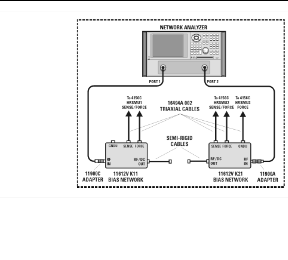
80 Installation and User’s Guide
2Installing the System
To connect the bias networks
Follow these steps to connect the bias networks to the system, and the
device under test to the bias networks.
Agilent 4156C Systems
To connect the bias networks
Step Action Notes
1For Agilent 4156C
systems, refer to the
following figure.
2Connect the triaxial
cables from the 4156C to
the bias networks.
aConnect the triaxial cables from the 4156C
HRSMU1 FORCE and SENSE connectors to
the DC FORCE and DC SENSE connectors
on the port 1 bias network.
bConnect the triaxial cables from the 4156C
HRSMU2 FORCE and SENSE connectors to
the DC FORCE and DC SENSE connectors
on the port 2 bias network.
•From the rear of the system, route the
cable through the feedthrough panel.
•The port 1 bias network is the 11612V
K11.
•The port 2 bias network is the 11612V
K21.
•Refer to Figure 5 on page 29.

Installing the System 2
Installation and User’s Guide 81
3Connect and route the
triaxial cable from 4156C
HRSMU3 FORCE
connector to the port 2
bias network.
aFrom the rear of the system, connect one
end of the triaxial cable to the HRSMU3
FORCE connector on the 4156C rear panel.
bFrom the rear of the system, route the cable
through the upper feedthrough panel.
cConnect the triaxial cable to the port 2 bias
network GNDU connector.
•The triaxial cable model number is
16494A Option 002.
•Leave the GNDU connector on the port
1 bias network open.
4Connect the Agilent
E8364B test ports to the
bias networks.
aConnect one end of the port 1 test port
cable to the Agilent E8364B test port 1.
bConnect the other end of the test port 1 test
port cable to the 2.4 mm female-to-male
adapter.
cConnect the 2.4 mm female-to-male
adapter to the RF IN connector on the
11612V Option K11 bias network.
dConnect one end of the port 2 test port
cable to the Agilent E8364B test port 2.
eConnect the other end of the test port 2 test
port cable to the 2.4 mm male-to-male
adapter.
fConnect the other end of the 2.4 mm
male-to-male adapter to the RF IN
connector of the 11612V K21 bias network.
•The test port cables model number is
85133F.
•The 2.4 mm female-to-male adapter
model number is 11900C. Without this
adapter, the test port cable will not
properly mate with the bias network
RF IN connector.
•The 2.4 mm male-to-male adapter
model number is 11900A.
5Connect the bias
networks to the device
under test.
aConnect one semi-rigid cable to the RF/DC
OUT connector of the port 1 bias network.
bConnect the other semi-rigid cable to the
RF/DC OUT connector of the port 2 bias
network.
cConnect the device under test to the
semi-rigid cable attached to the port 1 bias
network.
dConnect the device under test to the
semi-rigid cable attached to the port 2 bias
network.
•The semi-rigid cables part number is
85107-20004.
To connect the bias networks (continued)
Step Action Notes
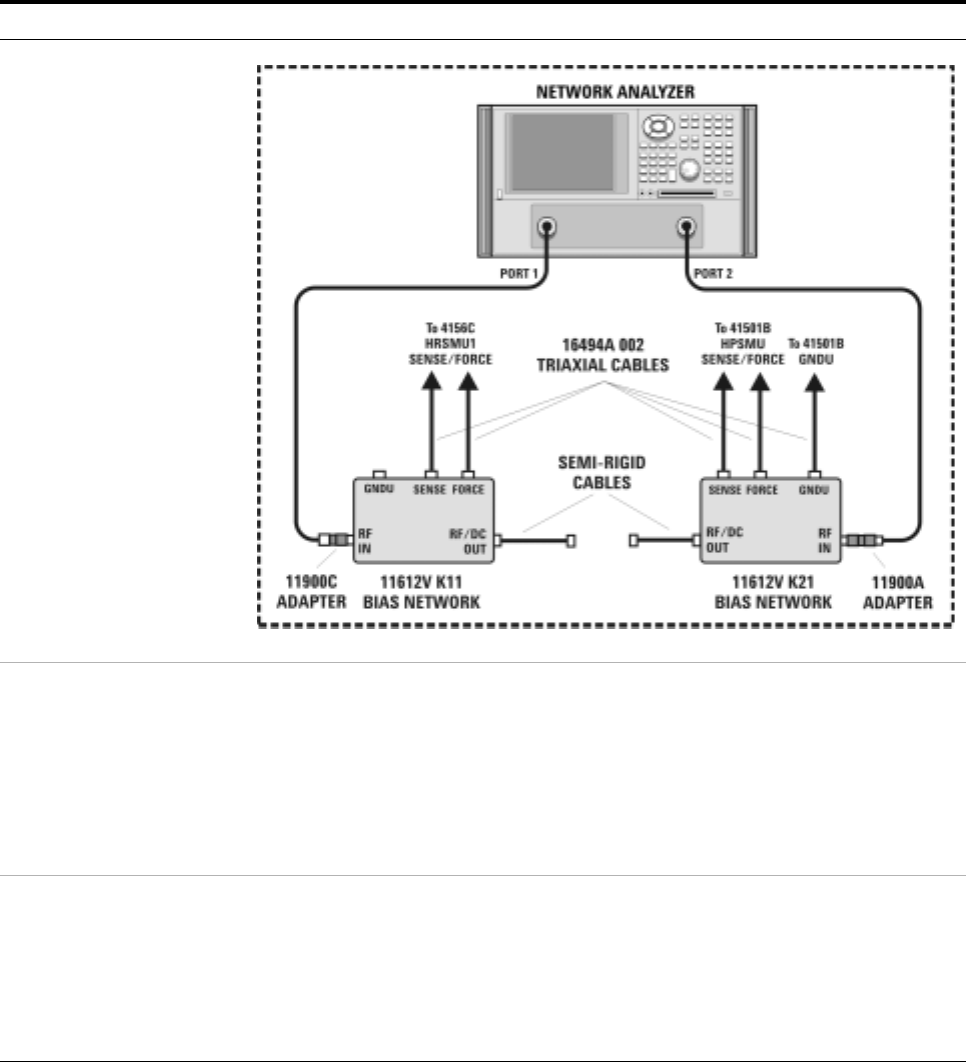
82 Installation and User’s Guide
2Installing the System
Agilent 4156C Systems with Agilent 41501B Expander Box
To connect the bias networks
Step Action Notes
1For Agilent 4156C with
41501B expander box
systems, refer to the
following figure.
2Connect the triaxial
cables from the 4156C to
the bias networks.
aConnect the triaxial cables from the 4156C
HRSMU1 FORCE and SENSE connectors to
the DC FORCE and DC SENSE connectors
on the port 1 bias network.
bConnect the triaxial cables from the 41501B
HPSMU FORCE and SENSE connectors to
the DC FORCE and DC SENSE connectors
on the port 2 bias network.
•From the rear of the system, route the
cable through the feedthrough panel.
•The port 1 bias network is the 11612V
K11.
•The port 2 bias network is the 11612V
K21.
•Refer to Figure 20,“Rear Panel Wiring
Diagram,” on page 53.
3Connect and route the
triaxial cable from 4156C
HRSMU3 FORCE
connector to the port 2
bias network.
aFrom the rear of the system, connect one
end of the triaxial cable to the GNDU
connector on the 41501B rear panel.
bFrom the rear of the system, route the cable
through the upper feedthrough panel.
cConnect the triaxial cable to the port 2 bias
network GNDU connector.
•The triaxial cable model number is
16494A Option 002.
•Leave the GNDU connector on the port
1 bias network open.
•Refer to Figure 3,“Front Panel
Connections with Agilent 4156C,” on
page 25.

Installing the System 2
Installation and User’s Guide 83
4Connect the Agilent
E8364B test ports to the
bias networks.
aConnect one end of the port 1 test port
cable to the Agilent E8364B test port 1.
bConnect the other end of the test port 1 test
port cable to the 2.4 mm female-to-male
adapter.
cConnect the 2.4 mm female-to-male
adapter to the RF IN connector on the
11612V Option K11 bias network.
dConnect one end of the port 2 test port
cable to the Agilent E8364B test port 2.
eConnect the other end of the test port 2 test
port cable to the 2.4 mm male-to-male
adapter.
fConnect the other end of the 2.4 mm
male-to-male adapter to the RF IN
connector of the 11612V K21 bias network.
•The test port cables model number is
85133F.
•The 2.4 mm female-to-male adapter
model number is 11900C. Without this
adapter, the test port cable will not
properly mate with the bias network
RF IN connector.
•The 2.4 mm male-to-male adapter
model number is 11900A.
5Connect the bias
networks to the device
under test.
aConnect one semi-rigid cable to the RF/DC
OUT connector of the port 1 bias network.
bConnect the other semi-rigid cable to the
RF/DC OUT connector of the port 2 bias
network.
cConnect the device under test to the
semi-rigid cable attached to the port 1 bias
network.
dConnect the device under test to the
semi-rigid cable attached to the port 2 bias
network.
•The semi-rigid cables part number is
85107-20004.
To connect the bias networks (continued)
Step Action Notes
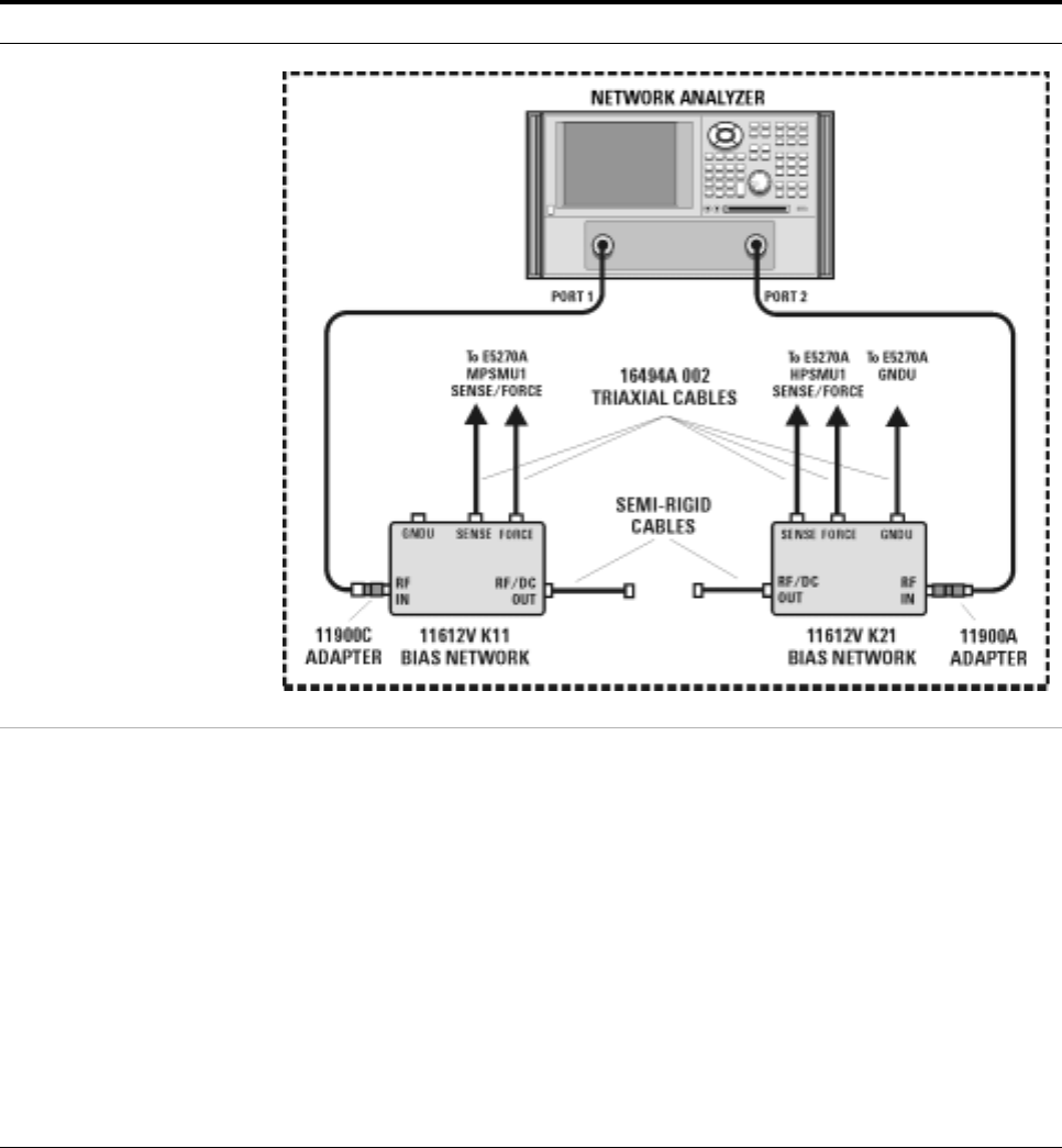
84 Installation and User’s Guide
2Installing the System
Agilent E5260A/70B Systems
To connect the bias networks
Step Action Notes
1For Agilent E5260A/70B
systems, refer to the
following figure.
2Connect the triaxial
cables to the E5260A/70B
SMUs.*
aFrom the front of the system rack, connect
triaxial cables to the front panel high power
SMU FORCE and SENSE outputs on the
E5260A/70B.
bConnect a triaxial cable to the front panel
medium power SMU FORCE and SENSE
outputs on the E5260A/70B.
cFrom the front of the system, route the
cable through the upper feedthrough panel.
dFrom the rear of the system, route the
HPSMU cable through the port 2 hole in the
lower feedthrough panel.
eFrom the rear of the system, route the
MPSMU cable through the port 1 hole in
the lower feedthrough panel.
•The triaxial cable model number is
16494A Option 002.
•The high speed high power SMU is the
Agilent E5290A.
•The high speed medium power SMU is
the Agilent E5291A.
•The high power SMU is the Agilent
E5280A.
•The medium power SMU is the Agilent
E5281A.
•Refer to Figure 4 on page 27

Installing the System 2
Installation and User’s Guide 85
3Connect the triaxial
cables from the
E5260A/70B SMUs to the
bias networks.
aConnect the triaxial cable from the
E5260A/70B medium power SMU to the
DC FORCE and DC SENSE connectors on
the port 1 bias network.
bConnect the triaxial cable from the
E5260A/70B high power SMU to the DC
FORCE and DC SENSE connectors on the
port 2 bias network.
•The medium power SMU is the Agilent
E5281A.
•The high power SMU is the Agilent
E5280A.
•The port 1 bias network is the 11612V
K11.
•The port 2 bias network is the 11612V
K21.
4Connect and route the
ground cable from
E5260A/70B GNDU to the
port 2 bias network.
aFrom the front of the system, connect one
end of the ground triaxial cable to the
GNDU connector on the E5260A/70B front
panel.
bFrom the front of the system, route the
cable through the upper feedthrough panel.
cFrom the rear of the system, route the
ground triaxial cable through the port 2 hole
in the lower feedthrough panel.
dConnect the ground triaxial cable to the
port 2 bias network GNDU connector.
•The ground triaxial cable model number
is 16493L Option 002.
•Leave the GNDU connector on the port
1 bias network open.
5Connect the Agilent
E8364B test ports to the
bias networks.
aConnect one end of the port 1 test port
cable to the Agilent E8364B test port 1.
bConnect the other end of the test port 1 test
port cable to the 2.4 mm female-to-male
adapter.
cConnect the 2.4 mm female-to-male
adapter to the RF IN connector on the
11612V Option K11 bias network.
dConnect one end of the port 2 test port
cable to the Agilent E8364B test port 2.
eConnect the other end of the test port 2 test
port cable to the 2.4 mm male-to-male
adapter.
fConnect the other end of the 2.4 mm
male-to-male adapter to the RF IN
connector of the 11612V K21 bias network.
•The test port cables model number is
85133F.
•The 2.4 mm female-to-male adapter
model number is 11900C. Without this
adapter, the test port cable will not
properly mate with the bias network
RF IN connector.
•The 2.4 mm male-to-male adapter
model number is 11900A.
To connect the bias networks (continued)
Step Action Notes

86 Installation and User’s Guide
2Installing the System
6Connect the bias
networks to the device
under test.
aConnect one semi-rigid cable to the RF/DC
OUT connector of the port 1 bias network.
bConnect the other semi-rigid cable to the
RF/DC OUT connector of the port 2 bias
network.
cConnect the device under test to the
semi-rigid cable attached to the port 1 bias
network.
dConnect the device under test to the
semi-rigid cable attached to the port 2 bias
network.
•The semi-rigid cables part number is
85107-20004.
* Refer to Figure 4, “Front Panel Wiring Diagram with Agilent E5260A or E5270B,” on page27.
To connect the bias networks (continued)
Step Action Notes
Installing the System 2
Installation and User’s Guide 87
To switch on power to the system
NOTE Proper system operation is dependent on the sequence in which the
system components are switched on.
To switch on power to the system
Step Notes
1Ensure that the individual instruments are
configured to match the available line power
source.*
•For information regarding line power
settings, refer to the individual instrument
manuals.
2Ensure that all component line power
switches are set to the OFF position.
3Connect the system to line power.
4Switch the rack cabinet ~ Line switch from
to (from standby to energized).
5Switch on the low leakage switch mainframe
line power.
6Switch on the precision LCR meter line
power.
7If present, on the 4284A SYSTEM CONFIG
page, highlight the value in the GPIB
ADDRESS field, and press 24 > Enter.
•This sets the correct system GPIB address
(24) for the 4284A.
8If present, on the 35670A front panel, press
Local/GPIB > ANALYZER ADDRESS > 22 >
ENTER.
•This sets the correct system GPIB address
(22) for the 35670A.
9If present, switch on the Agilent 4156C
precision semiconductor parameter analyzer
line power.
10 If present, switch on the 41501B expander
line power. •The expander must be switched on before
the 4156C.
11 Switch on the Agilent 4156C precision
semiconductor parameter analyzer line
power.
•Ensure that the 41501B has already been
switched on prior to activating the 4156C.
12 On the 4156C, press System >
[MISCELLANEOUS], move the pointer to the
POWER LINE FREQUENCY field, and press
[50 Hz] or [60 Hz].
•This ensures that the 4156C is configured to
match the available line power frequency.
•The value is set to 60 Hz at the factory.
•Use the front panel arrow keys to move the
cursor.

88 Installation and User’s Guide
2Installing the System
13 On the 4156C, press System >
[MISCELLANEOUS], highlight the 4156C
value in the GPIB ADDRESS field, and press
19 > Enter.
•This sets the correct system GPIB address
(19) for the 4156C.
14 On the E5260A/70B, move the cursor to
CONFIG, press Enter, move the cursor to
ADDRESS, press Enter. Use the arrow keys
to set the address to 19 and press Enter.
•This sets the correct system GPIB address
(19) for the E5260A/70B.
15 Switch on the Agilent E8364B PNA Series
vector network analyzer line power.
16 On the Agilent E8364B PNA Series vector
network analyzer, from the Main dialog,
select System > Configure > SICL/GPIB. In
the SICL/GPIB dialog GPIB group box, select
the Talker/Listener radio button and select
16 in the Address scroll list.
•This sets the correct system GPIB address
(16) for the E8364B.
17 If present, switch on the LAN/GPIB gateway
line power. Refer to the LAN/GPIB gateway documentation
for instruction on installation and configuration.
18 Switch on the computer line power.
19 Allow the system to warm up for one hour.
* If the system is to be used with an autotransformer, ensure that the common terminal is connected to the
neutral (grounded) side of the power source.
To switch on power to the system
Step Notes

Installing the System 2
Installation and User’s Guide 89
To configure the LAN/GPIB gateway for functional verification
If your system includes an Agilent E5810A LAN/GPIB gateway, follow
these steps to configure the LAN/GPIB gateway in order to verify the
functionality of the performance modeling system.
After functional verification, contact your corporate IT professional and
ask for a permanent server IP address assignment for the LAN/GPIB
gateway. For instructions on changing the server IP address, see the
LAN/GPIB gateway installation and configuration guide.
This completes the installation process. To confirm the functionality of the
system, continue to Chapter 3, “Verifying System Functionality,” starting
on page 91.
NOTE This procedure explains how to configure IC-CAP to use the default
LAN/GPIB gateway server IP address in order to verify the
functionality of the performance modeling system.
To configure the LAN/GPIB gateway
Step Action Notes
20 Start the IC-CAP
software.*
* To familiarize yourself with the IC-CAP software, refer to the first three chapters of the Agilent IC-CAP 2004 User’s Guide, model number
85190D.
PC version:
aSelect Start > Programs > IC-CAP 2004 >
IC-CAP.
UNIX version:
aOpen a UNIX terminal window.
bAt the prompt, type iccap.
cPress Enter.
•This starts IC-CAP and opens the
IC-CAP/Status and IC-CAP/Main
windows.
21 Add the interface to the
IC-CAP Hardware Setup. aFrom the IC-CAP/Main window menu bar,
choose Tools > Hardware Setup... .†
bBelow the HP-IB Interface group box, click
Add Interface.
cIn the Add HP-IB Interface dialog box, enter
lan[192.0.0.192]:hpib.
dClick OK.
† If there is an existing IC-CAP interface (for example, HP-IB), select the existing interface and click Delete Interface before continuing to
the next action.
•This opens the IC-CAP/Hardware
Setup window.
•This opens the Add HP-IB dialog box.
•This configures the LAN/GPIB
gateway (with its default server
address) as the performance modeling
system GPIB interface.
90 Installation and User’s Guide
2Installing the System

91
Agilent 85225F Performance Modeling System
Installation and User’s Guide
Agilent Technologies
3
Verifying System Functionality
To choose a verification process 92
Understanding the System Functional Verification Test 94
Performing the System Functional Verification Test 95
Related Topics “To enhance measurement accuracy" on page 112
“Performing a Coaxial System Measurement Calibration" on page 115
“Performing the DC Subsystem Functional Verification Test" on page121
“Performing the RF Subsystem Functional Verification Test" on page 125
Use the procedures in this chapter to verify the functionality of the
Agilent 85225F performance modeling system. This chapter includes
procedures for choosing varying degrees of functional verification and
performing the required post- installation system functional verification
test.

92 Installation and User’s Guide
3Verifying System Functionality
To choose a verification process
System functionality can be verified using several different processes,
depending on the level (system or subsystem) of functional verification
required and the available tools.
The procedure provided in “Performing the System Functional Verification
Test" on page 95 verifies that all of the system instruments interface
correctly, and that the system can make software- driven measurements
using a controller running the IC- CAP software.
Manual functional verification procedures for DC, RF, CV, and 1/f noise
subsystem components can be found in:
•Appendix B, “DC Subsystem Functional Verification Test,”
starting on page 119
•Appendix C, “RF Subsystem Functional Verification Test,”
starting on page 123
•Appendix D, “CV Subsystem Functional Verification Test,” starting on
page 129
•Appendix E, “1/f Noise Subsystem Functional Verification Test,” starting
on page 133
Follow these steps to choose a system functional verification process based
upon your current situation.
NOTE These tests do NOT verify that the system instrumentation conform to their individual
performance specifications.
To verify the performance of the individual system components, complete the appropriate
performance tests listed in their individual product documentation.
To choose a system verification process
Situation Action Note
1If the system has recently
been installed or one of
the DC or RF subsystem
instruments has been
replaced, and you have
IC-CAP software...
Complete the steps listed in “Performing the
System Functional Verification Test" on
page 95.
•Completion of the System Functional
Verification Test is required after
system installation, or whenever an RF
or DC subsystem component has been
serviced or replaced.
•The System Functional Verification Test
verifies the functionality of instruments
in the RF and DC subsystems. To verify
the functionality of other system
components, continue to the
appropriate situation listed in this
table.

Verifying System Functionality 3
Installation and User’s Guide 93
2If you would like to
manually check the
functionality of the
Agilent E8364B PNA
Series vector network
analyzer without using
the GPIB interface...
Complete the steps listed in “Performing the
RF Subsystem Functional Verification Test" on
page 125.
3If you would like to
manually check the
functionality of the
Agilent 4156C precision
semiconductor parameter
analyzer without using
the GPIB interface...
Complete the steps listed in “Performing the
DC Subsystem Functional Verification Test" on
page 121.
4If you would like to
manually check the
functionality of the
Agilent E5260A/70B
without using the GPIB
interface...
Complete the steps listed in “Performing the
DC Subsystem Functional Verification Test" on
page 121.
5If you would like to
manually check the
functionality of the
Agilent 4284A without
using the GPIB interface...
Complete the steps listed in “Performing the
CV Subsystem Functional Verification Test" on
page 131.
6If you would like to
manually check the
functionality of the
Agilent 35670A without
using the GPIB interface...
Complete the steps listed in “Performing the
1/f Noise Subsystem Functional Verification
Test" on page 135.
7If you would like to
manually check the
functionality of the
Agilent E5250 low leakage
switch mainframe without
using the GPIB interface...
Complete the Agilent E5250A self-test found in
Chapter 3 of the low leakage switch
mainframe user’s guide.
To choose a system verification process (continued)
Situation Action Note
94 Installation and User’s Guide
3Verifying System Functionality
Understanding the System Functional Verification Test
The system functional verification test is a standard IC- CAP measurement
and simulation procedure. The system performs DC and S- parameter
extraction, optimization, and simulation using a fixed 10 dB attenuator as
the device under test (DUT).
The procedure provided in “Performing the System Functional Verification
Test” confirms:
•the IC- CAP software can communicate with and control the system
instrumentation via GPIB (through the LAN/GPIB gateway, if so
configured)
•the system can make measurements and display the results
•the IC- CAP software can simulate data
•the IC- CAP software can converge the simulated data with the
extracted (measured) data
The system applies forward and reverse current to the attenuator and
monitors voltage at the attenuator’s input and output. IC- CAP then uses
the measured data to model the device- intrinsic resistances and
transmission line delay.
Required Tools
•Agilent 85225F performance modeling system
•A system controller*
•Agilent 85190A IC- CAP software
•Test port cables
•Agilent 8490D 10 dB fixed RF attenuator†
•BNC tee (2)‡
•Agilent 11900A, 2.4 mm male- to- male adapter
•Agilent 11900B, 2.4 mm female- to- female adapter
•Agilent 11900C, 2.4 mm female- to- male adapter
•Agilent 85056A 2.4 mm precision calibration kit, or
•Agilent 85056D 2.4 mm economy calibration kit
* For requirements, see “The System Controller" on page 59.
† These components are supplied as part of the system.
‡ For CV subsystem verification only
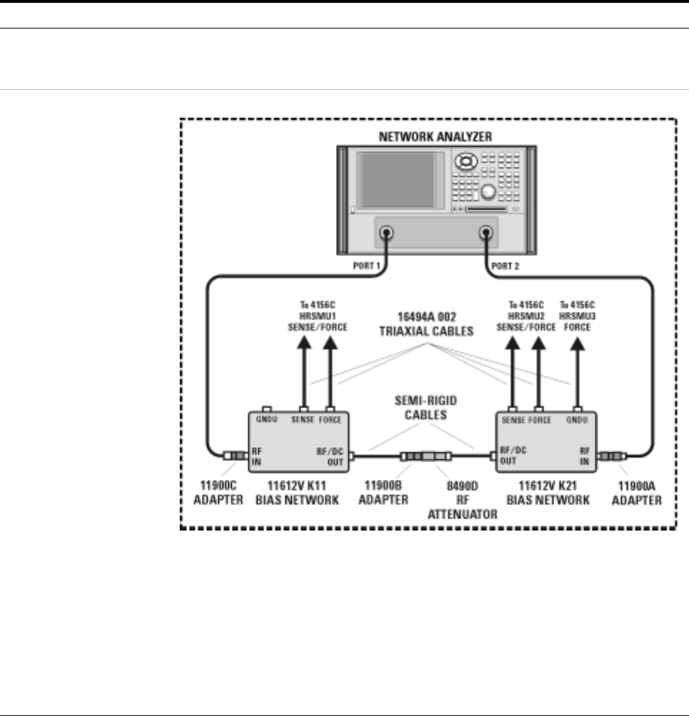
Verifying System Functionality 3
Installation and User’s Guide 95
Performing the System Functional Verification Test
Complete the following steps to verify system functionality using the
supplied Agilent 8490D 10 dB fixed RF attenuator as the device under
test.
To perform the system functional verification test
Step Action Notes
1Switch on power to the
system. aComplete the steps listed in “To switch on
power to the system" on page 87. •Proper system function is dependent
upon the order in which the system
components are switched on.
2Connect the device under
test to the bias networks. aRefer to the following figure.
bConnect one end of the 2.4 mm
female-to-female adapter to the semi-rigid
cable attached to the RF/DC OUT
connector of the port 1 bias network.
cConnect male end of the attenuator to the
other end of the 2.4 mm female-to-female
adapter.
dConnect the female end of the attenuator to
the semi-rigid cable attached to the RF/DC
OUT connector of the port 2 bias network.
•The 2.4 mm female-to-female adapter
is a 11900B. Use the 11900B provided
in the calibration kit.
•The port 1 bias network is a 11612V
K11.
•The port 2 bias network is a 11612V
K21.

96 Installation and User’s Guide
3Verifying System Functionality
3Start the IC-CAP
software.*PC version:
aSelect Start > Programs > IC-CAP 2004 >
IC-CAP.
UNIX version:
aOpen a UNIX terminal window.
bAt the prompt, type iccap.
cPress Enter.
•This starts IC-CAP and opens the
IC-CAP/Status and IC-CAP/Main
windows.
4Add the system interface
and components to the
IC-CAP Hardware Setup.
aFrom the IC-CAP/Main window menu bar,
choose Tools > Hardware Setup... .
bIf you have not added an interface, click
Add Interface, enter the system interface
(hpib or other), and click OK.
cIn the Instrument List, click Rebuild.
dVerify that all system components appear
in the Instrument List.
•This opens the IC-CAP/Hardware
Setup window.
•This polls the GPIB and adds all
connected and activated system
instruments to the Instrument List.
•Disregard error messages on the
system instrument displays. The errors
are a by-product of the GPIB polling
process.
5For 4156C systems,
change the Agilent 4156C
precision semiconductor
parameter analyzer
HRSMU names in IC-CAP.
aIn the Instrument List, select HP4156 (hpib,
19) and click Configure... .
bIn the Configuration of HP4156 window
Unit Table group box, highlight the
characters in the HRSMU1 entry box and
type VG.
cIn the Unit Table group box, highlight the
characters in the HPSMU entry box and
type VD.
dClick OK.†
eClose the Hardware Setup window.
•This opens the Configuration of
HP4156 window where the Unit Table
dialog box is used to change the names
of the HRSMUs.
•Actions b, c, and d change the name of
HRSMU1 to VG and HPSMU to VD.
•Renaming the SMUs is necessary for
proper execution of the example model
file.
6For E5260A/70B systems,
change the Agilent 4156C
precision semiconductor
parameter analyzer SMU
names in IC-CAP.
aIn the Instrument List, select Agilent E5270
(hpib, 19) and click Configure... .
bIn the Configuration of E5270 window Unit
Table group box, highlight the characters in
the MPSMU<slot number> entry box and
type VG.
cIn the Unit Table group box, highlight the
characters in the HPSMU<slot number>
entry box and type VD.
dClick OK.‡
eClose the Hardware Setup window.
•This opens the Configuration of E5270
window where the Unit Table dialog
box is used to change the names of the
SMUs.
•Actions b, c, and d change the name of
MPSMU<slot number> to VG and
HPSMU<slot number> to VD.
•Renaming the SMUs is necessary for
proper execution of the example model
file.
To perform the system functional verification test (continued)
Step Action Notes

Verifying System Functionality 3
Installation and User’s Guide 97
7Open the attenuator test
model in IC-CAP. aFrom the IC-CAP/Main window menu bar,
choose File > Examples... .
bIn the Directories list of the File Open dialog
box, double-click on the directory
.../examples/model_files.
cIn the Directories list of the File Open dialog
box, double-click on the directory
.../model_files/misc.
dIn the Files list of the File Open dialog,
double-click on sys_testrf.mdl.
•This opens the File Open dialog box.
•This opens a list of model files.
•(Scroll the list, if needed.) This displays
a list of modeling files in the Files list of
the File Open dialog.
•This opens the Atten model window.
•The Atten model window contains tab
folders used to interact with the model
data.
8Set the model variables
for the measurement in
IC-CAP.
aClick the Model Variables tab folder.
bHighlight the freq_start variable and enter
4.5E+07.
cHighlight the freq_stop variable and enter
50E+09.
dHighlight the imax variable and enter 90m.
•This opens the Model Variables tab
folder.
•This sets the start frequency of the
model to 45 MHz.
•This sets the stop frequency of the
model to 50 GHz.
•This sets the maximum current to
90 milliamps.
9Set the network analyzer
instrument options for the
attenuator test model in
IC-CAP.
aIn the DUTs-Setups tab folder, click
S_vs_freq in the Select DUT/Setup list.
bClick the Instrument Options tab folder.
cHighlight the Cal Type value and enter H.
dHighlight the Cal File Name value and enter
TEST.CST.
•This opens the 5 tab folders used for
the S_vs_freq setup.
•This opens the Instrument Options tab
folder.
•Adjustable instrument parameters are
listed in group boxes titled as
instrument model number.bus address.
instrument address (for example,
AgilentPNA.7.16 for the network
analyzer group box).
•Terminate your value entries by
pressing Enter on the controller
keyboard.
To perform the system functional verification test (continued)
Step Action Notes

98 Installation and User’s Guide
3Verifying System Functionality
10 Configure the instrument
state for calibration. aDisconnect the attenuator from the
semi-rigid cables.
bIn the Utility key group on the network
analyzer front panel, press Macro/Local >
Preset.
cIn the Channel menu, click Power... .
dIn the Power dialog box, scroll the Test Port
Power value to −20 dBm, then click OK.
eIn the Sweep menu, point to Number of
Points and click 101.
fIn the Sweep menu, select IF Bandwidth... .
gIn the IF Bandwidth dialog box, scroll to
1.000 kHz, then click OK.
hIn the Sweep menu, select Sweep Setup... .
iIn the Sweep Setup dialog box, select the
Stepped Sweep check box and click OK.
•This removes the instrument from GPIB
control, activates the front panel
interface, and returns the instrument to
its factory preset condition.
•Actions c through h prepare the
network analyzer for a full range 2-port
calibration using the same instrument
state settings used by the IC-CAP
functional verification test macro.
11 Calibrate the network
analyzer. aIn the network analyzer’s Calibration menu,
select Calibration Wizard... .
bIn the Calibration Wizard: Begin Calibration
dialog box, select SmartCal (GUIDED
Calibration): Use Mechanical Standards
radio button and click Next.
cFollow the displayed prompts to calibrate
the network analyzer.
•For detailed instructions, see
“Performing a Coaxial System
Measurement Calibration" on
page 115.
•This begins a modified full 2-port
calibration.
•When prompted to connect a standard
to either Port 1 or Port 2, connect the
standard to the semi-rigid cable
attached to the Port 1 or Port 2 bias
network.
•An isolation calibration is not needed
for this measurement.
12 Save the calibration and
instrument state data to
the C:/Program Files/
Agilent /Network
Analyzer/Documents
folder.
aIn the File menu, select Save As... .
bIn the Save As dialog box, using the
keyboard or by clicking Edit File Name,
enter TEST.CST then click OK.
•This saves the calibration and
instrument state data in the network
analyzer’s operating system
C:/Program Files/Agilent/
Network Analyzer/Documents folder.
To perform the system functional verification test (continued)
Step Action Notes

Verifying System Functionality 3
Installation and User’s Guide 99
13 Make the DC and RF
measurements in IC-CAP. aReconnect the attenuator.
bIn the Atten model window, click the
Macros tab.
cIn the Select Macro: list, select Test_atten
and click Execute.
dWhen prompted to ensure you have
calibrated the network analyzer, enter Y
and click OK.
eWhen prompted to enter a cal set number
use the default (1) and click OK.
fAs IC-CAP performs an optimization,
observe the simulated data trace converge
with the measured data trace.
•This opens the Atten model window’s
Macros tab folder.
•This starts a sequence of prompts and
responses.
•IC-CAP performs measurements of the
attenuator’s DC and RF parameters.
•When complete, IC-CAP displays plots
of the forward and reverse DC voltage
transfer through the attenuator. The
solid line is the measured data, the
dashed line is the simulated data.
•IC-CAP begins the optimization process
using default simulated data. These
values are optimized to converge with
the measured data.
14 Interpret the results. aObserve the displayed plots.
bIn the IC-CAP/Status window, observe the
final DC/RF values parameter and the Final
RMS error.
•When the S-parameter measurement is
complete, IC-CAP displays plots of the
S12/21, 20×log10 of the S21
magnitude, and S21 phase.**
•IC-CAP also lists the attenuator’s
resistance values. The error between
measured and simulated data should
be less than 2%.
•The error between the measured and
simulated S21 phase data should be
less than 2%.
•The value for T1.TD is the transmission
time through the attenuator, modeled
as transmission line delay. This value
(typically in the femtosecond to
nanosecond range) depends on the
length of the attenuator.
•The S21 magnitude and the S12/S21
plots, of less significance, are included
for your interest.
•The S21 simulated trace is determined
from the measured DC resistances, and
therefore is not expected to converge
with the measured data over the full
frequency range. However, the
measured S21 data will show a normal
frequency response variation.
•The S12/S21 plot (also displayed on
the network analyzer) confirms that the
system is capable of making forward
and reverse transmission
measurements.
To perform the system functional verification test (continued)
Step Action Notes

100 Installation and User’s Guide
3Verifying System Functionality
This completes the functional verification procedure.
15 For systems with the
Agilent 4284A precision
LCR meter, open the
junction capacitance
model (juncap.mdl) in
IC-CAP.
aFrom the IC-CAP/Main window menu bar,
choose File > Examples... .
bIn the Directories list of the File Open dialog
box, double-click on the directory
.../examples/model_files.
cIn the Directories list of the File Open dialog
box, double-click on the directory
.../model_files/diode.
dIn the Files list of the File Open dialog,
double-click on juncap.mdl.
•This opens the File Open dialog box.
•This opens a list of model files.
•(Scroll the list, if needed.) This displays
a list of modeling files in the Files list of
the File Open dialog.
•This opens the juncap model window.
•The juncap model window contains tab
folders used to interact with the model
data.
16 Select the DUT/Setup. aSelect the DUTs-Setups tab.
bClick the area > cv setup. •This opens the capacitance vs. voltage
setup.
17 Set the LCR meter
instrument options. aSelect the Instrument Options tab.
bHighlight the Cable Length variable and
enter 2.
•This sets the cable length in the LCR
meter instrument options.
18 Calibrate the LCR meter. aOn the 16048D test leads, connect one tee
between the Hpot and Hcur connectors.
bConnect the other tee between the Lpot and
Lcur connectors. Select the
Measure/Simulate tab.
cSelect Calibrate.
dFollow the IC-CAP prompts.
•This performs a calibration on the LCR
meter.
•The BNC tee part number is 1250-2405.
19 Measure the open circuit
capacitance. aSelect Measure.•This measures the open circuit
capacitance.
20 Observe the results aAfter the calibration is complete, observe
the plot.
bRescale the measured result (displayed in
red) cap.m.
•The measured result should be less
than ±10E-15 farads.
* To familiarize yourself with the IC-CAP software, refer to the first three chapters of the Agilent IC-CAP 2004 User’s Guide, model number
85190D.
† To save this hardware configuration: on the IC-CAP main menu bar, choose File > Save As and enter a filename, for example
config1.hwd (the file suffix must be .hwd).
‡ To save this hardware configuration: on the IC-CAP main menu bar, choose File > Save As and enter a filename, for example
config1.hwd (the file suffix must be .hwd).
**S12 is identical to S21 because the attenuator is assumed to be symmetrical.
To perform the system functional verification test (continued)
Step Action Notes
Verifying System Functionality 3
Installation and User’s Guide 101
If you encounter a problem
✔Check the system connections and settings:
1system connections to the DUT
2system interconnections
3GPIB cabling
4GPIB address settings
✔Perform the DC subsystem self- test in Appendix B, “DC Subsystem
Functional Verification Test,” starting on page 119.
✔Perform the Agilent E8364B PNA Series vector network analyzer
operator’s check in Appendix C, “RF Subsystem Functional Verification
Test,” starting on page 123.
✔Perform the Agilent 4284A precision LCR meter self- test in
Appendix D, “CV Subsystem Functional Verification Test,” starting on
page 129.
✔Perform the Agilent 35670A dynamic signal generator self- test in
Appendix E, “1/f Noise Subsystem Functional Verification Test,” starting
on page 133.
102 Installation and User’s Guide
3Verifying System Functionality

103
Agilent 85225F Performance Modeling System
Installation and User’s Guide
Agilent Technologies
4
Servicing the System
To troubleshoot the system 104
To remove or replace a system component 105
To order replacement parts 106
To receive additional assistance 107
Contacting Agilent Technologies 107
To package the system for transport 108
Related Topics “Performing the System Functional Verification Test" on page 95
“Component Integration" on page 48
Use this chapter to solve problems. This chapter includes a checklist for
troubleshooting the system, a procedure for removing a system component
from the rack cabinet, information on ordering replacement parts and
acquiring additional assistance to solve your measurement problem.
104 Installation and User’s Guide
4Servicing the System
To troubleshoot the system
Most system problems are caused by faulty cabling or switch
configurations.
Refer to Figure 20 on page 53 and Figure 19 on page 51 and do the
following:
✔Check system connections and settings:
1system connections to the DUT
2system interconnections
3GPIB cabling
4GPIB address settings
If the cabling and switch configurations are verified correct, do the
following:
✔Complete the Agilent E8364B PNA Series vector network analyzer
operator’s check in “Performing the RF Subsystem Functional
Verification Test" on page 125.
✔Complete the Agilent 4156C precision semiconductor parameter
analyzer self- test in “Performing the DC Subsystem Functional
Verification Test" on page 121.
✔Complete the Agilent 4284A self- test by cycling the instrument’s line
power. If errors occur, refer to Appendix B in the precision LCR meter
operation manual. The operation manual is included in with the
Agilent 85225F performance modeling system.
✔If you suspect trouble with the E2050B, see “Chapter 4
Troubleshooting” in the E5810A LAN/GPIB gateway installation and
configuration guide.
✔Complete the Agilent E5250A self- test and leak test found in Chapter 3
of the low leakage switch mainframe user’s guide. The user’s guide is
included with the Agilent 85225F performance modeling system.
If a problem with one of the system components is found, refer to the
troubleshooting and repair information in the individual instrument’s
product documentation.
For more information, see “To receive additional assistance" on page 107.
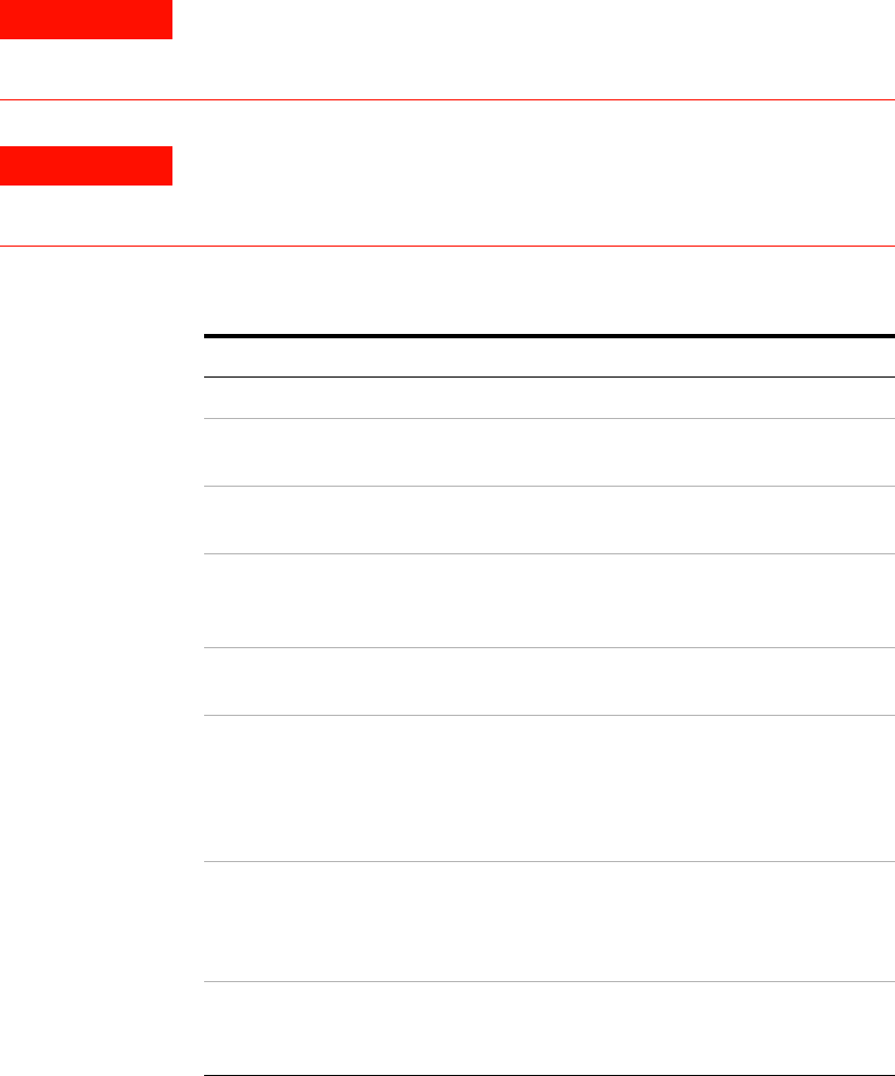
Servicing the System 4
Installation and User’s Guide 105
To remove or replace a system component
Follow these steps to remove a system component for periodic component
calibration, service, or repair.
Follow the steps in reverse order to replace a system component.
WARNING These servicing instructions are provided for use by qualified
personnel only. To avoid electrical shock, do not perform any
servicing unless you are qualified to do so.
WARNING The opening of covers or removal of parts is likely to expose
dangerous voltages. Disconnect the product from all voltage
sources before opening covers or removing parts.
To remove a system component
Step Note
1Turn off all components.
2Disconnect the system from line
power.
3Disconnect all cables from the
instrument to be removed.
4Prepare a surface near the rack
cabinet to place the removed
system component.
5Lower the stabilizing legs on the
rack cabinet.
6From the front of the rack cabinet,
remove the four screws (2 screws
on each rack mount) attaching the
instrument’s rack mount and
handle kit to the rack cabinet.
7As another person steadies the
rack cabinet, hold the instrument
by the rack mount handles and
slowly pull forward.
•Some components may weigh more
than 50 pounds and may require
more than one person to remove
safely.
8Save the rack mount screws by
reinserting them in the rack cabinet
frame nuts.
106 Installation and User’s Guide
4Servicing the System
Following the replacement of a system component, complete the procedure
in “Performing the System Functional Verification Test" on page 95.
To order replacement parts
To find the part or model number of a replaceable system component,
refer to Table 18, “Replaceable Parts,” on page 69.
To order, contact Agilent Technologies by calling the telephone number
listed in Table 19 on page 107 appropriate to the location of the modeling
system.
Servicing the System 4
Installation and User’s Guide 107
To receive additional assistance
If you would like assistance, visit the online assistance web site, or call
the telephone number listed in Table 19 appropriate to the location of
modeling system.
Table 19 Contacting Agilent Technologies
Online assistance: http://eesof.tm.agilent.com/support/
Australia
(tel) 1 800 629 485
(fax) (+61) 3 9210 5947
Canada
(tel) 1 877 894 4414
(fax) (905) 282-6495
Europe
(tel) (+31) 20 547 2323
(fax) (+31) 20 547 2390
Hong Kong
(tel) 800 930 871
(fax) (852) 2506 9233
India
(tel) 1 600 11 2929
(fax) 000 800 650 1101
Japan
(tel) (+81) 426 56 7832
(fax) (+81) 426 56 7840
Latin America
(tel) (305) 269 7500
(fax) (305) 269 7599
Malaysia
(tel) 1 800 828 848
(fax) 1 800 801
New Zealand
(tel) 0 800 738 378
(fax) (+64) 4 495 8950
People’s Republic of China
(tel) 800 810 0189 (preferred)
(tel) 10800 650 0021
(fax) 110800 650 0121
Philippines
(tel) (632) 8426802
(fax) (632) 8426809
Philippines (PLDT
Subscriber Only)
(tel) 1 800 16510170
(fax) 1 800 16510288
Singapore
(tel) 1 800 375 8100
(fax) (65) 836 0252
Taiwan
(tel) 0800 047 866
(fax) (886) 2 25456723
Thailand
(tel) (088) 226 008 (outside
Bangkok)
(tel) (662) 661 3999 (within
Bangkok)
(fax) 1 661 3714
United States
(tel) 1 800 829 4444

108 Installation and User’s Guide
4Servicing the System
To package the system for transport
Follow these instruction to package the system in a shipping crate.
To package the system for transport
Step Note
1Place the packaging base in an
unobstructed work area.
2Remove the lag bolt from one side
of the retaining piece.
3Swing unbolted end of retaining
piece outward.
4Attach loading ramp.
5Roll rack cabinet up ramp face first
until it is fully seated on base.
6Remove ramp.
7Swing retaining piece back to
original position.
8Secure retaining piece with bolt.
9Secure rack cabinet to base using
retaining brackets inserted in the
slot located on each side of the
packaging base.
10 Secure retaining brackets with bolt
and tighten.
11 Place antistatic bag over rack
cabinet.
12 Place cardboard/foam top cap on
top of rack cabinet.
13 Place folded ramp on top cap.
14 Place crate side panel and crate
front panel on to base (the side
panel, with wooden cleat, goes on
the outside of the front panel).
15 Connect both panels by hammering
klimps approximately every two
feet along the vertex.
16 Place the lid in position and attach
to all side panels and front panel
using klimps.

Servicing the System 4
Installation and User’s Guide 109
17 Add tip indicators and appropriate
labeling
18 Secure crate to packaging base
using band straps
To package the system for transport (continued)
Step Note
110 Installation and User’s Guide
4Servicing the System

111
Agilent 85225F Performance Modeling System
Installation and User’s Guide
Agilent Technologies
A
Enhancing Measurement Accuracy
To enhance measurement accuracy 112
Understanding System Measurement Calibration 114
Performing a Coaxial System Measurement Calibration 115
If you encounter a problem 116
Periodic System Component Calibration 117
Related Topics “Performing the System Functional Verification Test" on page 95
“Performing the RF Subsystem Functional Verification Test" on page 125
Use the procedures in this appendix to enhance the accuracy of your
measurements.

112 Installation and User’s Guide
AEnhancing Measurement Accuracy
To enhance measurement accuracy
Follow these instructions to enhance the accuracy of your
measurements.
To enhance measurement accuracy
Step Action Notes
1Inspect device
connections for foreign
materials or connector
damage.
aPrior to connecting the DUT, inspect the
bias network and semi-rigid RF cable
connectors for foreign materials or
damage.
bReplace any damaged connectors.
•Before using connectors for a critical
measurement, inspect the connector
interfaces with a microscope (~20X).
Look for dirt, contaminants, dented or
scratched outer conductor mating
surfaces, and damaged center
conductors.
2Clean the connectors. aRemove the systems power cord from the
power supply or place the supply breaker in
the tripped position.
bMove the connectors to a well ventilated
area.
cUse a swab dipped in clean isopropyl
alcohol to cleanse the outer conductor
mating surfaces and the ends of the center
conductors.
dBlow off the remaining alcohol with clean
compressed air.
eAllow adequate time for the alcohol fumes
to disperse before activating the system.
•Be careful not to let the alcohol get on
the insulator bead, as this may damage
the bead.
•Be careful not to exert too much force
on the center conductors, as they may
be damaged.
•Compressed air can reduce the
temperature of connectors
dramatically, and this can have a
significant effect upon the performance
of calibration and verification
components.
•If the connector components being
cleaned are to be used in a critical
measurement application, allow the
temperature of these components to
stabilize prior to use.
3Ensure proper system
warm-up time. aSwitch on line power to all of the system
components.
bAllow at least 1 hour warm-up prior to
making measurements.
•Follow the procedure in “To switch on
power to the system" on page 87.
•Do not switch off line power to the
system unless the system will not be
used for an extended period of time.
4Ensure a proper and
constant temperature in
the measurement
environment.
aOperate the system within an ambient
temperature range of 25°C, ±5°C.
bAfter system measurement calibration,
hold the ambient temperature of the
measurement environment to ±1°C of the
ambient temperature at the time of
calibration.
•Install heating and cooling systems as
necessary to maintain proper ambient
temperature in the measurement
environment.

Enhancing Measurement Accuracy A
Installation and User’s Guide 113
5Always perform a
measurement calibration
on the network analyzer
prior to making device
measurements.
aPrior to making device measurements,
complete the steps listed in “Performing a
Coaxial System Measurement
Calibration" on page115.
bEnsure that the calibration kit elements are
seated correctly and firmly in the test set
cable connectors.
•See “Understanding System
Measurement Calibration" on page 114
for more information.
•Use the Agilent 85056A 2.4 mm
precision calibration kit.
•Use the Agilent 85056D 2.4 mm
economy calibration kit.
•Use the Agilent 85033E 3.5 mm
economy calibration kit.
•Use the Agilent 85052D 3.5 mm
economy calibration kit.
•Torque measurement connections
using the torque wrench provided in
the calibration kit.
6Calibrate the system
components at regular
intervals.
aEvery 6 to 12 months:
•Perform the required Agilent E8364B
PNA Series vector network analyzer
performance verification tests.
•Perform the required Agilent 4156C
precision semiconductor parameter
analyzer performance verification tests.
•Perform the required Agilent 4248A
precision LCR meter performance
verification tests.
•Perform the required Agilent E5250A low
leakage switch mainframe performance
verification tests.
To enhance measurement accuracy (continued)
Step Action Notes
114 Installation and User’s Guide
AEnhancing Measurement Accuracy
Understanding System Measurement Calibration
Measurement accuracy is degraded by the effects of three different types
of measurement errors: systemic, drift, and random.
Systemic errors are caused by imperfection in the test equipment and test
setup.
Drift errors occur when a test system’s performance changes after a
calibration has been performed. Drift errors are caused primarily by
variations in the ambient temperature of the measurement environment.
Random errors are caused by instrument noise (sampler noise, IF noise
floor, etc.), switch repeatability and connector repeatability. These errors
vary randomly as a function of time.
You can compensate for systemic and drift errors by performing a system
measurement calibration prior to measuring a device. (Performing a
measurement calibration has no effect upon random errors.)
To increase the accuracy of your measurements, perform a system
measurement calibration before performing device measurements. Repeat
the measurement calibration if the ambient temperature of the
measurement environment has deviated ±1°C since the last measurement
calibration.
This procedure performs a modified full 2- port measurement calibration to
remove the following errors:
•Directivity
•Source- load match
•Reflection tracking
•Transmission tracking
The isolation calibration (crosstalk correction) has been omitted. Isolation
calibration is only required when measuring high- isolation devices such as
a switch in the open position or high- dynamic range devices such as
filters with a high level of rejection.
Required Tools
•Agilent 85225F performance modeling system
•Agilent 85056A 2.4 mm calibration kit, or
•Agilent 85056D 2.4 mm calibration kit

Enhancing Measurement Accuracy A
Installation and User’s Guide 115
Performing a Coaxial System Measurement Calibration
Complete the following steps to perform a coaxial system measurement
calibration and increase the accuracy of your device measurements. Modify
these instructions as necessary to perform an in- fixture or on wafer
measurement calibration.
To perform the system measurement calibration
Step Action Note
1Preset the network
analyzer. On the network analyzer, press Preset.
2Open the Calibration
Wizard and choose a
guided calibration.
aIn the network analyzer’s Calibration menu,
select Calibration Wizard... .
bIn the Calibration Wizard dialog box, select
Use Mechanical Stds... in the Guided
Calibrations group box.
3Choose the DUT
connector types. aIn the Guided Calibration: Select DUT
Connectors dialog box, select the
appropriate DUT connector type for the
connections the Port 1 and Port 2 bias
networks.
bClick Next.
4Choose the calibration kit. aIn the Guided Calibration: Select Version 2
Cal Kits dialog box, select the appropriate
calibration kit (for example 85056D) for the
Port 1 and Port 2 bias network.
bClick Next.

116 Installation and User’s Guide
AEnhancing Measurement Accuracy
If you encounter a problem
✔Inspect the connectors on the load, open, short, and through standards
and the connectors on the bias networks and the semi- rigid cables.
✔Clean the connectors if necessary. See step 2 in the section titled “To
enhance measurement accuracy" on page 112.
✔If connectors are damaged, replace the standard or cable.
✔Ensure that the standards meet their published specifications.
5Calibrate the network
analyzer through the bias
networks, cables, and
adapters using the
standard open, short,
load, and through.
aFollow the prompts to connect the standard
open to the Port 1 bias network RF/DC
OUTPUT.
bClick Measure.
cFollow the prompts to connect the standard
short to the Port 1 bias network RF/DC
OUTPUT.
dClick Measure.
eFollow the prompts to connect the standard
broadband load to the Port 1 bias network
RF/DC OUTPUT.
fClick Measure.
gRepeat actions a through f for the Port 2
calibration measurements.
hFollow the prompts to connect the standard
through between the Port 1 and Port 2 bias
networks RF/DC OUTPUT. connectors.
iClick Measure.
jWhen the measurements are done, in the
Standards Measured dialog box, click Next.
kIn the Guided Calibration Completed dialog
box, choose the No, Finish Now radio
button and click Finish.
6Save the calibration and
instrument state data to
the C:/Program Files/
Agilent /Network
Analyzer/Documents
folder.
aIn the File menu, select Save As... .
bIn the Save As dialog box, using the
keyboard or by clicking Edit File Name,
enter a file name (for instance,
MY_CAL.CST), then click OK.
•This saves the calibration and
instrument state data as a file (named
for instance, MY_CAL.CST) in the
network analyzer’s operating system
C:/Program Files/Agilent/
Network Analyzer/Documents folder.
To perform the system measurement calibration (continued)
Step Action Note
Enhancing Measurement Accuracy A
Installation and User’s Guide 117
Periodic System Component Calibration
A complete calibration verifies that the system components meet their
individual performance specifications.
The calibration interval depends on the level of system use. Agilent
Technologies recommends an initial cycle of 6 to 12 months. Thereafter,
adjust the cycle based on the recalibration results.
A complete system calibration consists of the following tests:
•Agilent E8364B PNA Series vector network analyzer performance tests*
•Agilent 4156C precision semiconductor parameter analyzer performance
verification†
•Agilent E5260A/70B precision parametric measurement solution
performance verification
•Agilent 4284A precision LCR meter performance tests
•Agilent 35670A dynamic signal analyzer performance verification
•Agilent E5250A low leakage switch mainframe performance tests
See the individual instrument documentation for instructions on
performing the required instrument verification tests.
* Refer to the Agilent E8364B PNA Series vector network analyzer service guide for required performance tests.
The service guide (part number E8364-90026) is available at www.agilent.com in PDF format.
† Refer to the chapter titled “Performance Verification” in the Agilent 4156C precision semiconductor
parameter analyzer service guide, included with the Agilent 4156C documentation.
118 Installation and User’s Guide
AEnhancing Measurement Accuracy

119
Agilent 85225F Performance Modeling System
Installation and User’s Guide
Agilent Technologies
B
DC Subsystem Functional Verification
Test
Understanding the DC Subsystem Functional Verification Test 120
Performing the DC Subsystem Functional Verification Test 121
If you encounter a problem 121
Related Topics “Performing the System Functional Verification Test" on page 95”
“Performing the RF Subsystem Functional Verification Test" on page 125”
“Performing the CV Subsystem Functional Verification Test" on page 131
“Performing the 1/f Noise Subsystem Functional Verification Test" on
page 135
Use this appendix to perform a DC subsystem functional verification test
using the Agilent 4156C precision semiconductor parameter analyzer’s
front panel interface.
120 Installation and User’s Guide
BDC Subsystem Functional Verification Test
Understanding the DC Subsystem Functional Verification Test
Use this procedure to manually confirm the functionality of the DC
subsystem. The procedure provided in “Performing the DC Subsystem
Functional Verification Test” confirms:
For Agilent 4156C subsystems:
•the internal operation of the Agilent 4156C precision semiconductor
parameter analyzer
For Agilent E5260A/70B DC subsystems:
•the operation of the Agilent E5260A/70B parametric measurement
mainframe
•the operation of the plug- in source monitor units
This procedure runs a self- test initiated from the instrument’s front panel.
The test includes a self- calibration routine to improve short- term
accuracy.
Required Tools
•Agilent 4156C precision semiconductor parameter analyzer,
•Agilent E5260A/70B parametric measurement mainframe

DC Subsystem Functional Verification Test B
Installation and User’s Guide 121
Performing the DC Subsystem Functional Verification Test
Complete these steps to run the self- test and verify the operation the DC
subsystem.
For Agilent 4156C subsystems:
If you encounter a problem
✔Refer to the Agilent 4156C precision semiconductor parameter analyzer
manual titled, “If You Have a Problem” for an explanation of the error
codes. See the chapter titled, “If Errors Occur When You Perform
Self- Calibration or Diagnostics.”
✔Refer to the troubleshooting information in the service manual for the
Agilent 4156C precision semiconductor parameter analyzer.
To perform the Agilent 4156C precision semiconductor parameter analyzer self-test
Step Notes
1Disconnect all cables from the
measurement terminals on the
4156C rear panel.
2Connect the 4156C to line power.
3Switch on the instrument line
power switch.
4Wait 1 hour before continuing to
step 5.
5Press System > [CALIB/DIAG]. •The analyzer displays the SYSTEM:
SELF-CALIBRATION/DIAGNOSTICS
screen.
6Press [DIAG SELFTST ALL]. •This begins the calibration and
self-test process.
•PASS, FAIL, or DONE appear in the
STATUS column.
•If a failure occurs, an error code is
displayed in the ERROR column. See
“If you encounter a problem.”
•If no errors occur, DIAG SELF-TEST
ALL: PASS appears in the lower
left-hand corner of the display.

122 Installation and User’s Guide
BDC Subsystem Functional Verification Test
For Agilent E5260A/70B DC subsystems:
If you encounter a problem
✔Refer to the Agilent E5260A/70B precision parametric measurement
solution user’s guide for an explanation of the error codes. See the
section titled “Error Codes” in the chapter titled, “If You Have a
Problem.”
✔Refer to the troubleshooting information in the Agilent E5260A/70B
precision parametric measurement solution service manual.
To perform the Agilent E5260A/70B precision parametric measurement solution self-test
Step Notes
1Disconnect all cables from the
measurement terminals on the
E5260A/70B front panel.
2Connect the E5260A/70B to line
power.
3Switch on the instrument line
power switch.
4Wait 1 hour before continuing to
step 5.
5Press Shift > Menu.
6Move the cursor to SELFTEST and
press Enter. Move the cursor to
EXECUTE and press Enter.
7Use the arrow keys to select ALL
and press Enter. At the completion
of the test, press Exit three times to
exit the setup menu.
8To display the results, move the
cursor to SELFTEST and press
Enter. Move the cursor to RESULT
and press Enter.
9Use the arrow keys to select
FRAME or Slot n. The test result is displayed for each
item.

123
Agilent 85225F Performance Modeling System
Installation and User’s Guide
Agilent Technologies
C
RF Subsystem Functional Verification
Test
Understanding the RF Subsystem Functional Verification Test 124
Performing the RF Subsystem Functional Verification Test 125
If you encounter a problem 127
Related Topics “Performing the System Functional Verification Test" on page 95
“Performing the DC Subsystem Functional Verification Test" on page121
“Performing the CV Subsystem Functional Verification Test" on page 131
“Performing the 1/f Noise Subsystem Functional Verification Test" on
page 135
Use the instructions in this appendix to perform a manual RF subsystem
functional verification test.
124 Installation and User’s Guide
CRF Subsystem Functional Verification Test
Understanding the RF Subsystem Functional Verification Test
Use the procedure provided in “Performing the RF Subsystem Functional
Verification Test” to manually confirm the functionality of the
Agilent E8364B PNA Series vector network analyzer system. This
procedure does not verify performance to specification. This procedure
confirms that the network analyzer is ready for performance verification
and/or operation by confirming the following hardware functionality:
•the repeatability of the RF switch in the test set
•the attenuation range of the test port attenuators
Required Tools
•Agilent E8364B PNA Series vector network analyzer
•Test port cable
•a standard short from the network analyzer calibration kit
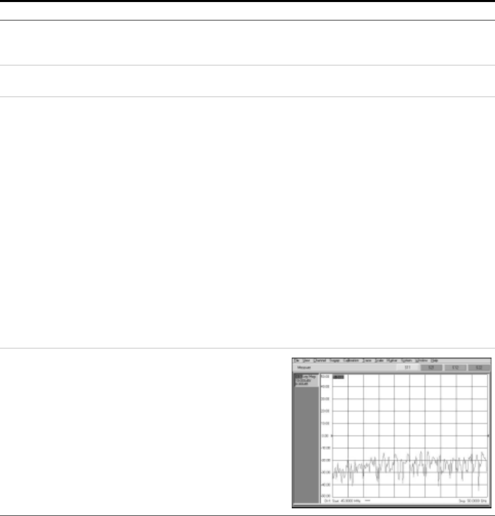
RF Subsystem Functional Verification Test C
Installation and User’s Guide 125
Performing the RF Subsystem Functional Verification Test
If the performance of the Agilent E8364B PNA Series vector network
analyzer is in question, complete the following steps to verify operation.
To perform the RF subsystem functional verification test
Step Action Notes
1Activate the network
analyzer. aConnect the network analyzer to
line power.
bSwitch on the line power.
2Warm-up the network
analyzer for 1 hour. aWait 1 hour before continuing to
step 3.
3Run the Operator’s Check. aIn the network analyzer System
menu, point to Service and click
Operator’s Check.
bClick Configure.
cOn the pull down menu, select
Automatic.
dClick Start-Port 1.
eFollow the program prompts.
fWhen prompted, place a short on
Port 1 and click OK.
gCheck PASS/FAIL status.
hContinue to follow the prompts for
the Attenuator Range tests.
iCheck PASS/FAIL status for each
attenuator range.
jClick Start-Port 2.
kRepeat actions e through i for Port 2.
lClick Exit to end the Operator’s
Check.
•This opens the Operator’s Check window.
•This selects automatic program execution. To
enable a prompted test sequence, choose
Prompted to place a prompt before the
execution of each range test for each
attenuator.
•When the Port 1 test is complete, the
Operator’s Check window reappears showing
the test results for Port 1.
•When the Port 2 test is complete, the
Operator’s Check window reappears showing
the test results for Port 2.
4Test the forward reflection
mode for channel 1.aConnect the test port cable between
the PORT 1 and PORT 2 connectors.
bPress Preset. (By default, the
instrument measures channel 1
forward reflection after instrument
preset.
cInspect the trace shown on the
display. It should be similar to the
trace shown to the right.
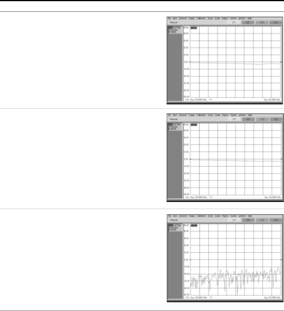
126 Installation and User’s Guide
CRF Subsystem Functional Verification Test
5Test the forward
transmission mode for
channel 1.
aFrom the Trace drop down menu,
point to Measure and click S21.
bInspect the trace shown on the
display. It should be similar to the
trace shown to the right.
6Test the reverse
transmission mode for
channel 1.
aFrom the Trace drop down menu,
point to Measure and click S12.
bInspect the trace shown on the
display. It should be similar to the
trace shown to the right.
7Test the reverse reflection
mode for channel 1.aFrom the Trace drop down menu,
point to Measure and click S22.
bInspect the trace shown on the
display. It should be similar to the
trace shown to the right.
To perform the RF subsystem functional verification test (continued)
Step Action Notes
RF Subsystem Functional Verification Test C
Installation and User’s Guide 127
If you encounter a problem
✔Check the GPIB cable and connection.
✔Check the GPIB address.
✔Consult the “Troubleshooting” chapter of the Agilent E8364B PNA
Series vector network analyzer service guide for troubleshooting
information.
128 Installation and User’s Guide
CRF Subsystem Functional Verification Test

129
Agilent 85225F Performance Modeling System
Installation and User’s Guide
Agilent Technologies
D
CV Subsystem Functional Verification
Test
Understanding the CV Subsystem Functional Verification Test 130
Performing the CV Subsystem Functional Verification Test 131
If you encounter a problem 132
Related Topics “Performing the System Functional Verification Test" on page 95
“Performing the RF Subsystem Functional Verification Test" on page 125
“Performing the DC Subsystem Functional Verification Test" on page121
Use the instructions in this appendix to perform a manual CV subsystem
functional verification test.
130 Installation and User’s Guide
DCV Subsystem Functional Verification Test
Understanding the CV Subsystem Functional Verification Test
Use the procedure provided in “Performing the CV Subsystem Functional
Verification Test” to manually confirm the functionality of the
Agilent 4284A precision LCR meter. This procedure does not verify
performance to specification. This procedure confirms that the precision
LCR meter is ready for performance verification and/or operation by
confirming the following hardware functionality:
•memory card read/write test
•LED display test
•LCD display test
•handler I/F test
•scanner I/F EEPROM read/write test
•scanner I/F I/O test
•bias current I/F I/O test
Required Tools
See Chapter 10 of the Agilent 4284A precision LCR meter operation
manual.

CV Subsystem Functional Verification Test D
Installation and User’s Guide 131
Performing the CV Subsystem Functional Verification Test
If the performance of the Agilent 4284A precision LCR meter is in
question, complete the following steps to verify operation.
To perform the RF subsystem functional verification test
Step Action Notes
1Activate the precision LCR
meter. aConnect the precision LCR meter to
line power.
bSwitch on the line power.
2Warm-up the network
analyzer for 1 hour. aWait 1 hour before continuing to
step 3.
3Run the required self
tests. aOn the precision LCR meter front
panel, press CATALOG/SYSTEM >
SELF TEST.
bEnter the number corresponding to
the required self test and press
SELF TEST.
•This opens the SELF TEST page.
•For more information, see chapter 5
“Catalog/System Configuration” in the
Agilent 4284A precision LCR meter operation
manual.
132 Installation and User’s Guide
DCV Subsystem Functional Verification Test
If you encounter a problem
✔Check the GPIB cable and connection.
✔Check the GPIB address.
✔Consult the Agilent 4284A precision LCR meter service guide for
troubleshooting information.

133
Agilent 85225F Performance Modeling System
Installation and User’s Guide
Agilent Technologies
E
1/f Noise Subsystem Functional
Verification Test
Understanding the 1/f Noise Subsystem Functional Verification Test 134
Performing the 1/f Noise Subsystem Functional Verification Test 135
If you encounter a problem 136
Related Topics “Performing the System Functional Verification Test" on page 95
“Performing the DC Subsystem Functional Verification Test" on page121
“Performing the RF Subsystem Functional Verification Test" on page 125
“Performing the CV Subsystem Functional Verification Test" on page 131
Use the instructions in this appendix to perform a manual 1/f noise
subsystem functional verification test.
134 Installation and User’s Guide
E1/f Noise Subsystem Functional Verification Test
Understanding the 1/f Noise Subsystem Functional Verification Test
Use the procedure provided in “Performing the 1/f Noise Subsystem
Functional Verification Test” to manually confirm the functionality of the
Agilent system. This procedure does not verify performance to
specification. This procedure confirms that the network analyzer is ready
for performance verification and/or operation.
Required Tools
•Agilent 35670A dynamic signal analyzer

1/f Noise Subsystem Functional Verification Test E
Installation and User’s Guide 135
Performing the 1/f Noise Subsystem Functional Verification Test
If the performance of the Agilent 35670A dynamic signal analyzer is in
question, complete the following steps to verify operation.
To perform the RF subsystem functional verification test
Step Action Notes
1Activate the dynamic
signal analyzer. aConnect the dynamic signal
analyzer to line power.
bSwitch on the line power.
The instrument performs the self test during
power-up.
2View the results. aObserve the results on the analyzer
display. If the instrument self test fails, consult “Chapter
4. Troubleshooting the Analyzer,” in the Agilent
35670A dynamic signal analyzer service guide.
136 Installation and User’s Guide
E1/f Noise Subsystem Functional Verification Test
If you encounter a problem
✔Check the GPIB cable and connection.
✔Check the GPIB address.
✔Consult the “Chapter 4. Troubleshooting the Analyzer” in the
Agilent 35670A dynamic signal analyzer service guide for
troubleshooting information.

137
Agilent 85225F Performance Modeling System
Installation and User’s Guide
Agilent Technologies
F
Understanding the Bias Networks
Features 138
Characteristics 139
Operation 140
Bias Network Schematic 140
Related Topics “To connect the bias networks" on page 80
“Performing a Coaxial System Measurement Calibration" on page 115
Use this appendix to learn more about the bias networks. This appendix
includes a list of features, connections, a table of device characteristics,
information on internal operation, and a schematic diagram of the bias
networks.
138 Installation and User’s Guide
FUnderstanding the Bias Networks
Features
Using the Agilent 11612V K11 and K21 bias networks, you can
simultaneously supply DC bias and RF energy to the device under test
(without the need to use patch cables or adapters) to make convenient
and accurate DC and S- parameter measurements.
Each bias network provides:
•floating triaxial FORCE connection to input current or voltage
•floating triaxial SENSE connection to monitor voltage or current
•floating triaxial GNDU connection to implement an active ground
•2.4 mm coaxial RF input
•2.4 mm coaxial combined RF/DC output
•device bias oscillation suppression

Understanding the Bias Networks F
Installation and User’s Guide 139
Characteristics
Table 20 11612V Option K11/K21 Bias Network Characteristics
Parameter 11612V Option K11 11612V Option K21
Test port Port 1 Port 2
Frequency range 45 MHz to 50 GHz 45 MHz to 50 GHz
Test port connector 2.4 mm 2.4 mm
Maximum current 0.5 amps 0.5 amps
Maximum voltage 40 volts 40 volts
Maximum RF power 2 watts (+33 dBm) 2 watts (+33 dBm)
Height 50 mm (2 inches) 50 mm (2 inches)
Width 105 mm (3.5 inches) 105 mm (3.5 inches)
Depth 70 mm (2.75 inches) 70 mm (2.75 inches)
Net weight 370 grams (0.8 pounds) 370 grams (0.8 pounds)
CAUTION Do not exceed the maximum ratings of the bias networks. Failure to
comply can result in severe damage.
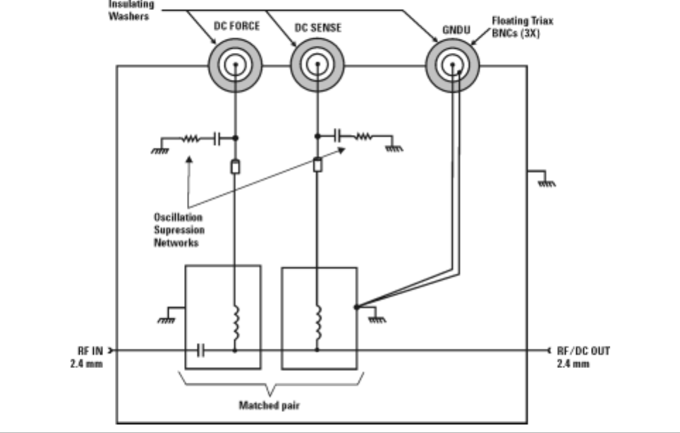
140 Installation and User’s Guide
FUnderstanding the Bias Networks
Operation
Each bias network includes two bias tees, one for force and one for sense.
The force bias tee includes a capacitor in the RF signal path that functions
as a high- pass filter and DC block. The sense bias tee provides a through
path for DC. Both force and sense tees include resistive- capacitive
oscillation suppression circuitry to help prevent low frequency bias
oscillation of the device under test. Refer to Figure 24.
Figure 24 Bias Network Schematic

141
Agilent 85225F Performance Modeling System
Installation and User’s Guide
Agilent Technologies
G
Network Analyzer Performance
Specification Summary
Network Analyzer System Performance 142
Dynamic Range 142
Measurement Uncertainty 143
Related Topics “RF and DC Measurement System Configuration" on page 19
“Performance Characteristics and Specifications" on page 61
Use this appendix to reference a summary of the network analyzer
performance specifications.

142 Installation and User’s Guide
GNetwork Analyzer Performance Specification Summary
Network Analyzer System Performance
The following specifications describe the system performance of the
Agilent E8364B PNA Series vector network analyzer Option 014 and UNL
configuration for measurements between 45 MHz and 50 GHz.
Calibration Kit Agilent 85056A, 2.4 mm precision, with sliding loads
Cables Agilent 85133F, 2.4 mm flexible test port cable set
Calibration Type Full 2- port with sliding loads
Temperature
Range 25°C ±5°C
Warm-up Time ≥ 0.5 hour
Maximum Output Power
Dynamic Range
System dynamic range is calculated as the difference between the noise
floor and the source maximum output power. Reflection measurements are
limited by directivity. Therefore, system dynamic range only applies to
transmission measurements.
Frequency Range (GHz)
0.045 to 10.0 10.0 to 20.0 20.0 to 30.0 30.0 to 40.0 40.0 to 45.0 45.0 to 50.0
Maximum output power +3 dBm 0 dBm −4 dBm −8 dBm −11 dBm −17 dBm
Frequency Range (GHz)
0.045 to 0.5 0.5 to 2.0 2.0 to 10.0 10.0 to 20.0 20.0 to 30.0 30.0 to 40.0 40.0 to 45.0 45.0 to 50.0
System
dynamic
range
92 dB 117 dB 120 dB 119 dB 109 dB 105 dB 102 dB 95 dB
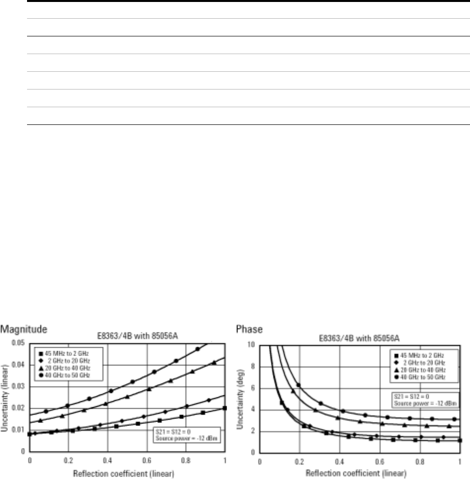
Network Analyzer Performance Specification Summary G
Installation and User’s Guide 143
Measurement Port Characteristics
Measurement Uncertainty
Measurement uncertainty curves utilize an RSS (Root Sum Square) model
for the contribution of random errors such as noise and typical connector
and test set switch repeatabilities. These are combined with a worst- case
model for the contributions of dynamic accuracy and residual systemic
errors.
Curves show the worst- case magnitude and phase uncertainty for
reflection and transmission measurements, using the specified cal kit, with
10 Hz IF bandwidth, and no averaging during the measurement.
Reflection Measurements
Frequency Range (GHz)
Residual 0.045 to 2.0 2.0 to 20.0 20.0 to 40.0 40.0 to 50.0
Directivity 42 dB 42 dB 38 dB 36 dB
Source match 41 dB 38 dB 33 dB 31 dB
Load match 42 dB 42 dB 37 dB 35 dB
Reflection tracking ±(0.001 + 0.2 dB/°C) ±(0.008 + 0.2 dB/°C) ±(0.020 + 0.3 dB/°C) ±(0.027 + 0.4 dB/°C)
Transmission tracking ±(0.019 + 0.2 dB/°C) ±(0.053 + 0.2 dB/°C) ±(0.114 + 0.3 dB/°C) ±(0.215 + 0.4 dB/°C)
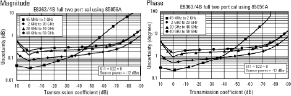
144 Installation and User’s Guide
GNetwork Analyzer Performance Specification Summary
Transmission Measurements
Installation and User’s Guide 145
Index
Numerics
11612V. See bias networks
2.4 mm (f-to-f) adapter,69, 94
2.4 mm (f-to-m) adapter,69, 81, 83, 85, 94
2.4 mm (m-to-f) adapter,69
2.4 mm (m-to-m) adapter,69, 81, 83, 85, 94
35670A. See dynamic signal analyzer
41501B. See expander, SMU PGU
4156C. See parameter analyzer
4284A. See LCR meter
A
accuracy, enhancing measurement,112
activation procedure, system,87
adapter, 2.4 mm (f-to-f),69, 94
adapter, 2.4 mm (f-to-m),69, 81, 83, 85, 94
adapter, 2.4 mm (m-to-f),69
adapter, 2.4 mm (m-to-m),69, 81, 83, 85, 94
altitude requirements,64
assistance, to receive additional,107
attenuator
fixed, 10 dB,71
test model, IC-CAP,97
B
ballast,71
bias networks
characteristics,139
connection procedure,80
connections, system,80
features,138
operational theory,140
overview,21
block diagram, 1/f noise measurement,47
block diagram, CV system,33
block diagram, system,19
C
cable set, test port,71
cable(s)
GPIB,69
line power,71
semi-rigid,71
SMU triaxial,69, 70
test set,71
cabling diagram, DC/RF,32, 40, 41, 54, 55
calibration
component,113, 117
isolation,114
kit,71
measurement,113, 115
cautions
bending packing clamps,66
bias network voltage/current rating,21, 139
circuit breaker protection,7
definition of caution label,3
electrostatic discharge,79
front panel line switch,8
line power disconnection,7
line power settings,7
mains cable connection,7
overcurrent protection,8
characteristics
bias networks,139
measurement port,143
supplemental system,61
checklist, receiving,69
cleaning, connector,112
clearance requirements, rack,64
compliance with
electrostatic discharge immunity test,9
EMC requirements,9
noise requirements,9
surge immunity test,9
compliance, CSA 1010,8
compliance, statement of,8
conformity, declaration of,8
connections, system,28, 36, 50, 52
controller, system
overview,59
CPU requirements, controller,59
crate, shipment
packing procedure,108
unpacking procedure,66
CSA 1010 compliance,8
customer support, Agilent Technologies,107
D
DC subsystem. See parameter analyzer or
parametric measurement solution
declaration of conformity,8
diagrams
block, 1/f noise measurement,47
block, CV system,33
block, system,19
cabling, DC/RF,32, 40, 41, 54, 55
integration, system component,35, 49
reflection uncertainty, network analyzer,143
test setup, verification,95
transmission uncertainty, network
analyzer,144
wiring, system,27, 29, 37, 39, 51, 53
digital multimeter, GPIB address,56
display requirements, controller,59
drift measurement errors,114
dynamic range,114, 142
dynamic signal analyzer
calibration cycle,117
functional verification procedure,
manual,134
GPIB address,56
overview,46
E
E5250A. See switch mainframe
E5260A/70B. See parametric measurement
solution
E5810A. See LAN/GPIB gateway
E8364B. See network analyzer
electrical requirements,64
electrostatic discharge
immunity test, compliance with,9
precautions against,79
EMC requirements, compliance with,9
environmental requirements,64
errors, measurement, correcting,114
expander, SMU PGU
overview,20
extractor fan,71
F
fan, extractor,71
feedthrough panels,71
floating-ground measurements
procedure,78
safety precautions,78
functional verification procedure
dynamic signal analyzer, manual,135
LCR meter, manual,131
network analyzer, manual,125
system, remote,95
G
GPIB
addresses,56
cables,69
connections,29, 39, 53
146 Installation and User’s Guide
Index
H
handle kit, rack mount and,70, 71, 105
hard disk requirements, controller,59
hardware setup, IC-CAP,89, 96
I
IC-CAP software
adding components,89, 96
adding interface,96
changing SMU names,96
configuring the interface,89
DC characterization,99
opening attenuator test model,97
saving the hardware configuration,100
setting network analyzer options,97
starting the program,89, 96
user’s guide,89, 100
inspection
connector surfaces,112
incoming shipment,65, 68
installation procedure,64
instrument markings,5
integration
description,22, 34, 48
diagram, system,35, 49
interface setup, IC-CAP,89
interference standards,61
isolation calibration,114
L
LAN/GPIB gateway
configuration procedure,89
default server address,89
GPIB address,56
overview,57
LCR meter
functional verification,100
functional verification procedure,
manual,130
GPIB address,56
options, setting in IC-CAP,100
overview,34
troubleshooting,104
line power
activating system,87
cables,71
requirements
circuit sharing,64
supply capability,64
M
maintenance, connector,112
manual part number,71
markings, instrument,5
measurement
accuracy, enhancing,112
calibration,115
description,114
procedure,115
DC characterization, using IC-CAP,99
errors, correcting,114
uncertainties
correcting,115
reflection,143
transmission,144
model/part numbers,69
mounting plates, probe station,69
N
network analyzer
calibration
cycle,117
procedure,98, 116
connections, system,28, 36, 50, 52
functional verification procedure,
manual,124
GPIB address,56
options, setting IC-CAP,97
overview,20
specification summary, performance,142
noise requirements, compliance with,9
O
operating system requirements, controller,59
output power, maximum,142
P
panels
feedthrough,71
filler,72
parameter analyzer
calibration cycle,117
functional verification procedure,
manual,121
GPIB address,56
parametric measurement solution
calibration cycle,117
connections, system,28, 36, 50, 52
GPIB address,56
specifications,62
parts, replaceable
list of,69
ordering,106
power, maximum output,142
precision parametric measurement solution
GPIB address,56
procedures
activating system line power,87
bias network connection,80
calibration, measurement,115
floating ground measurement,78
functional verification
dynamic signal analyzer,134
full system,95
LCR meter,130
network analyzer,124
parameter analyzer,121
installation,64
LAN/GPIB interface configuration in
IC-CAP,89
removal and replacement, component,105
safety precautions,76
shipment reception,65
site preparation,64
troubleshooting, system,104
unpacking shipment crate,66
work surface installation,74
R
rack
cabinet,60, 71
mount kit,70, 71, 105
rail kits,71
RAM requirements, controller,59
random measurement errors,114
receiving checklist,69
reflection uncertainty, network analyzer,143
relative humidity requirements,64
removal and replacement, component,105
replaceable parts
list of,69
ordering,106
required tools
crate, unpacking shipment,66
DC source/monitor functional
verification,120
measurement calibration,114
modeling system functional verification,94
network analyzer functional verification,124,
130, 134
work surface installation,74
requirements
controller
pc,59
UNIX,59
system
electrical,64
environmental,64
requirements, safety,5
results, interpreting,99
RF subsystem. See network analyzer
S
safety
precautions
floating-ground measurements,78
general,76
procedure,76
requirements,5
symbols, descriptions,4
Index
Installation and User’s Guide 147
schematic diagrams
DC/RF signal flow,32, 40, 41, 54, 55
semi-rigid cables,71
shipment reception procedure,65
site preparation procedure,64
SMU names, IC-CAP,96
SMU triaxial cables,69, 70
specifications, performance
E8364B network analyzer,142
parametric measurement solution,62
standards, interference,61
statement of compliance,8
support, customer,107
surge immunity test, compliance with,9
swap space requirements, controller,59
switch mainframe
GPIB address,56
overview,42
troubleshooting,104
symbols, safety,4
systemic measurement errors,114
T
temperature requirements,64
test setup diagram, verification,95
tools, required. See required tools
transmission uncertainty, network analyzer,144
troubleshooting
calibration, measurement,116
LAN/GPIB gateway,104
modeling system,104
network analyzer manual verification,127,
132, 136
parameter analyzer manual verification,121
U
uncertainties, measurement
correcting,115
reflection,143
transmission,144
V
verification, functional
description of choices,92
dynamic signal analyzer
procedure, manual,135
LCR meter,100
procedure, manual,131
modeling system
description,94
procedure, remote,95
network analyzer
description,124, 130, 134
procedure, manual,125
parameter analyzer
description,120
procedure, manual,121
parametric measurement solution
description,120
virtual memory requirements, controller,59
W
warnings
cover removal,105
dangerous voltages present,76, 78
definition of warning label,3
eye protection during unpacking,66
moving the rack cabinet,67
precautions for cleaning,8
protective earth contact interruption,6
protective earth ground connection,8
Safety Class 1 product,6
service with qualified personnel only,6
servicing by qualified personnel only,105
unspecified use,6
use in explosive atmosphere,6
window manager requirements, controller,59
wiring diagram, system,27, 29, 37, 39, 51, 53
work surface
installation procedure,74
part number,71
148 Installation and User’s Guide
Index
