Agilion 6021318 for identification and localization in the WIRELESS LOCATION SYSTEM User Manual 15 WIRELESS TAG DRIVE UserMan
Agilion GmbH for identification and localization in the WIRELESS LOCATION SYSTEM 15 WIRELESS TAG DRIVE UserMan
Agilion >
15_WIRELESS TAG DRIVE UserMan

WIRELESS TAG DRIVE
User Guide
Benutzerhandbuch

FCC ID: SCF6021318
This device complies with part 15 of the FCC Rules.
Operation is subject to the following two conditions: (1) This device may not cause harmful interfer-
ence, and (2) this device must accept any interference received, including interference that may cause
undesired operation.
Modifications not expressly approved by this company could void the user's authority to operate the
equipment.
Note: This equipment has been tested and found to comply with the limits for a Class A digital de-
vice, pursuant to part 15 of the FCC Rules. These limits are designed to provide reasonable protec-
tion against harmful interference when the equipment is operated in a commercial environment. This
equipment generates, uses, and can radiate radio frequency energy and, if not installed and used in
accordance with the instruction manual, may cause harmful interference to radio communications.
Operation of this equipment in a residential area is likely to cause harmful interference in which case
the user will be required to correct the interference at his own expense.
This device and its antenna must not be co-located or operating in conjunction with any other antenna
or transmitter.
This device has been designed to operate with the antennas listed below, and having a maximum gain
of 6 dB. Antennas not included in this list or having a gain greater than 6 dB are strictly prohibited for
use with this device. The required antenna impedance is 50 ohms.
IC: 10971A-6021318
This device complies with Industry Canada licence-exempt RSS standards.
Operation is subject to the following two conditions: (1) This device may not cause interference, and
(2) this device must accept any interference, including interference that may cause undesired opera-
tion of the device.
This device has been designed to operate with the antennas listed below, and having a maximum gain
of 6 dB. Antennas not included in this list or having a gain greater than 6 dB are strictly prohibited for
use with this device. The required antenna impedance is 50 ohms.
Le présent appareil est conforme aux CNR d'Industrie Canada applicables aux appareils radio
exempts de licence.
L'exploitation est autorisée aux deux conditions suivantes : (1) l'appareil ne doit pas produire de
brouillage, et (2) l'utilisateur de l'appareil doit accepter tout brouillage radioélectrique subi, même si le
brouillage est susceptible d'en compromettre le fonctionnement.
Ce dispositif a été conçu pour fonctionner avec les antennes indiquées ci-dessous, et
ayant un gain maximum de 6 dB. Il est strictement interdit d’utiliser les antennes ne figurant pas dans
cette liste ou présentant un gain supérieur à 6 dB avec ce dispositif. L’impédance d’antenne requise
est 50 ohms.
Use the following Agilion Antennas only:
• Omni/2dBi/FME-M
• Omni/6dBi/N-F/360°

20130314-6021318-UM 1 EN
Table of contents
English
1 Functionality ................................................................................................................. 2
2 Layout and Connections ............................................................................................... 3
2.1 Connectors and Indicators ........................................................................................ 4
2.2 Pin-Assignment ......................................................................................................... 4
3 Initial operation and Usage ......................................................................................... 5
4 Troubleshooting ........................................................................................................... 6
4.1 General errors ........................................................................................................... 6
5 Technical data............................................................................................................... 7
6 Declaration of Conformity ............................................................................................. 8

2 20130314-6021318-UM EN
1 Functionality
The WIRELESS TAG DRIVE is localized in Agilions WIRELESS LOCATION SYSTEM. It is attached to
vehicles or devices to determine the position or presence in a defined room. The transmission of
additional application specific data from and to the mobile tags is possible optionally.
The WIRELESS TAG DRIVE is designed for use in vehicles with 24 V power supply.

20130314-6021318-UM 3 EN
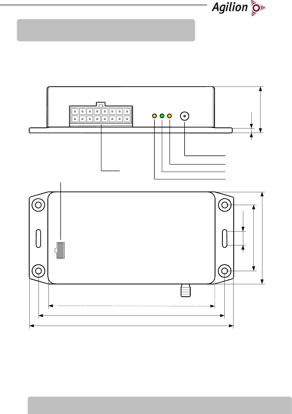
2 Layout and Connections
P1
Antenna (P3)
(RP-SMA)
Radio-LED (D1)
Power-LED (D2)
137,4
mm
62mm
44,5mm
9,3mm
112mm
125,2mm
31,1mm
3mm
Bus-LED (D3)
Fuse
4 20130314-6021318-UM EN
2.1
Connectors and Indicators
Connection Specification
P1 - POWER, Digital Power supply and digital inputs
P3 - Antenna RP-SMA - Antenna plug
D1 - Function-LED Blink when the WIRELESS TAG DRIVE is localized
D2 - Power-LED Lights when the WIRELESS TAG DRIVE is on, blinks on error
D3 - Bus-LED Blinks while activity at bus system
Fuse Vehicle Fuse, Mini Fuse, 5 A
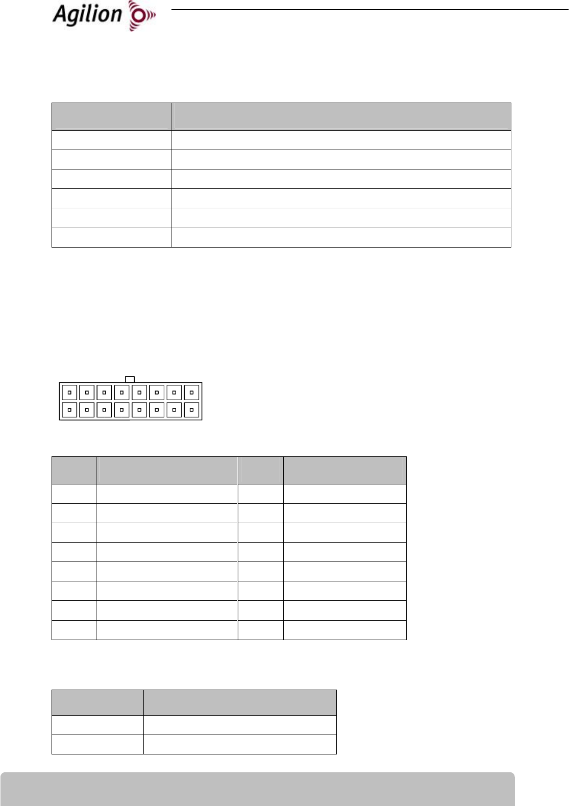
2.2
Pin-Assignment
P1 - POWER, Digital - Plug
16-pol Plug WR-MPC4
0.33 mm2 to 1.31 mm2
Pin Description Pin Description
1 IBIS OCM 9
IBIS OC
2 IBIS RM 10
IBIS RD
3 IBIS CM 11
IBIS CD
4 Digital Input 3 12
Digital Input 4
5 Digital Input 1 13
Digital Input 2
6 CAN-High 14
CAN-Low
7 Digital Output 1 15
Digital Output 2
8 24 V DC (e.g. KL 30) 16
GND (e.g. KL 31)
P3 - Antenna - RP-SMA plug
Pin Description
1 Antenna
Shield GND, Shield
16 9
18

20130314-6021318-UM 5 EN
3 Initial operation and Usage
Warning: Installation in railway vehicles or buses must be done by skilled and qualified personal
only.
Warning: The emitted antenna power shall not exceed 20 dBm (100 mW). The output power must
be adjusted in the way:
power of the module + attenuation of the antenna cable + gain/attenuation of the antenna < 20 dBm
Installation of the WIRELESS TAG DRIVE
1. The antenna (P3) must be attached to the RP-SMA-connection at the WIRELESS module.
Notice: Do not operate the WIRELESS module without the antenna. To change or dismount
the antenna switch off power supply or remove fuse.
Notice: The antennas should be justified in the same direction on all WIRELESS modules.
Notice: The WIRELESS modules should be placed in line of sight and in a high position for op-
timal wireless data transmission.
2. Set up power connection (P1). During start-up all LED’s are flashing once. The power-LED
(D2) keeps on lighting.
3. All cables connected to the WIRELESS modules should be fixed with the screws provided.
4. The WIRELESS modules must be protected against humidity.

6 20130314-6021318-UM EN
4 Troubleshooting
4.1
General errors
Effect Reason Action
Module does not work, Run
LED is off
Battery flat, fuse broken or
module not connected
Charge battery, check cables,
check fuse
Blinking Run LED Error in Module Switch WIRELESS module off and
on for reset, if error occurs
frequently contact
service@agilion.de

20130314-6021318-UM 7 EN
5 Technical data
Radio
Wireless technology IEEE 802.15.4a nanoLOC, - Chirp Spread Spectrum (CSS)
Data rates 1 MBit
Operating frequency 2.45 GHz ISM-Band
Chirp-bandwidth 80 MHz
Output power max. 100 mW, adjustable
Range @ 1 MBit Indoor max. 90 m, Outdoor max. 1,000 m (typical 500m)
Connectors and Power
Supply voltage 24 V DC
Power consumption max. 0.06 A - 1.6 W
Power connector 16-pol plug WR-MPC4
0.33 mm2 to 1.31 mm2
Fuse Min Fuse, 5 A
Input-and Output
Input Voltage 0 to 24 V DC
Input Impedance 4,7 kOhm
Output High-Side-Switch
Output Current max. 250 mA, short-circuit proof
Output Voltage 0 V or Supply Voltage
Environment
Case plastic housing
IP-protection IP 20, coated
Dimension 138 x 62 x 31 mm
Weight 125 g
Mounting 4 screw holes for M4 countersunk head screw
Temperature range -40 to +70°C

8 20130314-6021318-UM EN
6 Declaration of Conformity
The Agilion GmbH declares the conformity of
WIRELESS TAG DRIVE
according to the requirements of the standards:
EN300328
EN 301489
EN 60950-1
EN 50155 (usage in railway vehicles)
EN 50121-3-2
WIRELESS TAG DRIVE therefore complies with the EC-directives:
72/245/EEC ( – Typ permission for usage in automobile)
2002/95/EC (RoHS)
This declaration applies to all devices bearing the symbol. Validity is lost if modifications are
made to the product.
The WIRELESS TAG DRIVE underlies the 2002/96/EC and must be disposed separate form munici-
pal waste.
Dipl.-Inf. Sven Sieber Dipl.-Kfm.(FH) Andreas Werner
(Managing Director) (Managing Director)
Agilion GmbH
Blankenauer Str. 74
09113 Chemnitz
Germany
e1

20130314308-UM 1
DE
Inhaltsverzeichnis
Deutsch
1 Überblick....................................................................................................................... 2
2 Mechanik und Anschlüsse ............................................................................................ 3
2.1 Anschlüsse und Anzeigen.......................................................................................... 4
2.2 Pin-Belegung ............................................................................................................. 4
3 Inbetriebnahme und Installation ................................................................................. 5
4 Behebung von Störungen ............................................................................................. 6
4.1 Allgemeine Fehler...................................................................................................... 6
5 Technische Daten ......................................................................................................... 7
6 Konformitätserklärung ................................................................................................. 8

2 20130314-6021318-UM
DE
1 Überblick
Das WIRELESS TAG DRIVE wird im WIRELESS LOCATION SYSTEM von Agilion lokalisiert. Es wird in
Fahrzeugen bzw. Geräten eingesetzt um deren räumliche Position festzustellen oder die Anwe-
senheit in definierten Bereichen zu detektieren. Weiterhin ist eine Übertragung anwenderspezifi-
scher Daten von und zu den mobilen Tags möglich.
Das WIRELESS TAG DRIVE ist für den Einbau in Fahrzeugen mit 24 V Bordspannung geeignet.
20130314308-UM 3
DE
2 Mechanik und Anschlüsse
P1
Antenne (P3)
(RP-SMA)
Funk-LED (D1)
Power-LED (D2)
137,4
mm
62mm
44,5mm
9,3mm
112mm
125,2mm
31,1mm
3mm
Bus-LED (D3)
Sicherung
4 20130314-6021318-UM
DE
2.1
Anschlüsse und Anzeigen
Anschluss / Anzeige Beschreibung
P1 - POWER, Digital Stromversorgung und digitale Eingangssignale
P3 - Antenne RP-SMA - Antennenanschluss
D1 - Funktions-LED LED zur Signalisierung der Aktivität während der Lokalisierung
D2 - Power-LED Signalisiert den Betriebszustand
D3 – Bus-LED LED zur Signalisierung der Aktivität auf den Bus-Systemen
Sicherung Kfz-Sicherung, Mini-Fuse, 5 A
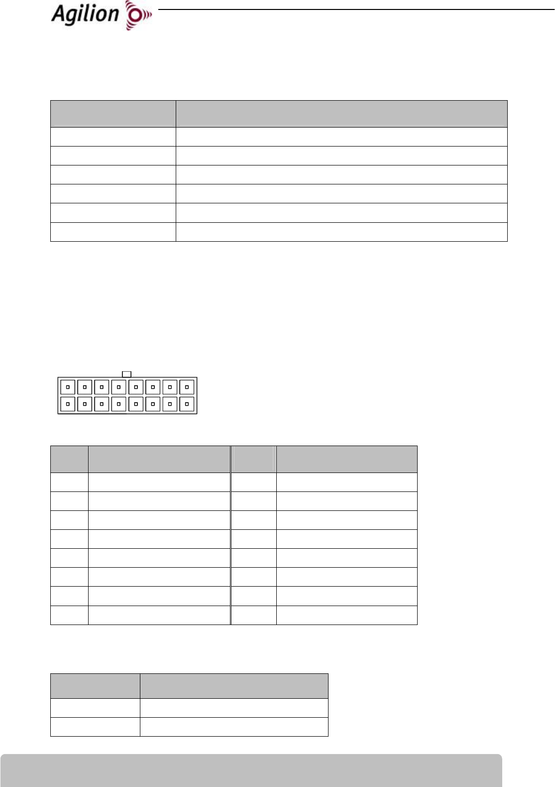
2.2
Pin-Belegung
P1 - POWER, Digital - Steckverbinder
16-poliger Steckverbinder Würth WR-MPC4
0,33 mm2 bis 1,31 mm2
Pin Beschreibung Pin
Beschreibung
1 IBIS OCM 9
IBIS OC
2 IBIS RM 10
IBIS RD
3 IBIS CM 11
IBIS CD
4 Digitaler Eingang 3 12
Digitaler Eingang 4
5 Digitaler Eingang 1 13
Digitaler Eingang 2
6 CAN-High 14
CAN-Low
7 Digitaler Ausgang 1 15
Digitaler Ausgang 2
8 24 V DC (z.B. KL 30) 16
Masse/GND (z.B. KL 31)
P3 - Antenne - RP-SMA Stecker
Pin Beschreibung
1 Antenne
Shield Schirmung
16 9
18

20130314308-UM 5
DE
3 Inbetriebnahme und Installation
Achtung: Die Installation des WIRELESS TAG DRIVE in Kraft- und Bahnfahrzeugen muss durch
entsprechend qualifiziertes und geschultes Fachpersonal erfolgen.
Achtung: Die Abgestrahlte Leistung vom WIRELESS TAG DRIVE, Antennenkabel und Antenne darf
20dBm (100mW) nicht überschreiten. Entsprechend ist die Ausgangsleistung des WIRELESS TAG
DRIVE so einzustellen, dass:
Leistung Modul + Dämpfung Antennenkabel + Verstärkung/Dämpfung Antenne < 20dBm
Installation des WIRELESS TAG DRIVE
1. Antenne an RP-SMA-Anschluss (P3) anschließen.
Achtung: Das WIRELESS Modul darf nicht ohne Antenne betrieben werden. Zum Wechseln
oder Entfernen der Antenne ist das Gerät auszuschalten bzw. stromlos zu schalten.
Hinweis: Die Antennen sind an allen WIRELESS-Modulen gleich auszurichten.
Hinweis: Um eine optimale Übertragung zu ermöglichen, sind die Antennen der WIRELESS-
Module möglichst weit oben und in Sichtverbindung anzubringen.
2. Anschluss der Stromversorgung an den Power-Eingang (P1) des Moduls. Dabei leuchten alle
LEDs initial auf.
3. Alle Kabel an den WIRELESS-Modulen sind mit einer Zugentlastung zu versehen, um die Ver-
bindungen zwischen Kabel und Endstück gegen mechanische Beanspruchungen zu schützen.
4. Die WIRELESS-Module müssen vor Feuchtigkeit geschützt werden.

6 20130314-6021318-UM
DE
4 Behebung von Störungen
4.1
Allgemeine Fehler
Fehlererkennung Fehlerursache Fehlerbehebung
WIRELESS-Modul reagiert
nicht, LEDs leuchten nicht
Modul nicht angeschlossen
oder nicht eingeschaltet
Stromversorgung des Moduls
prüfen, Modul angeschalten,
Stecker oder Steckerbelegung
prüfen
Blinkende Power-LED
während des Betriebs
Fehler in Modul Rücksetzen durch Aus- & An-
schalten des Moduls; tritt der
Fehler mehrfach auf, kontaktie-
ren sie bitte service@agilion.de
20130314308-UM 7
DE
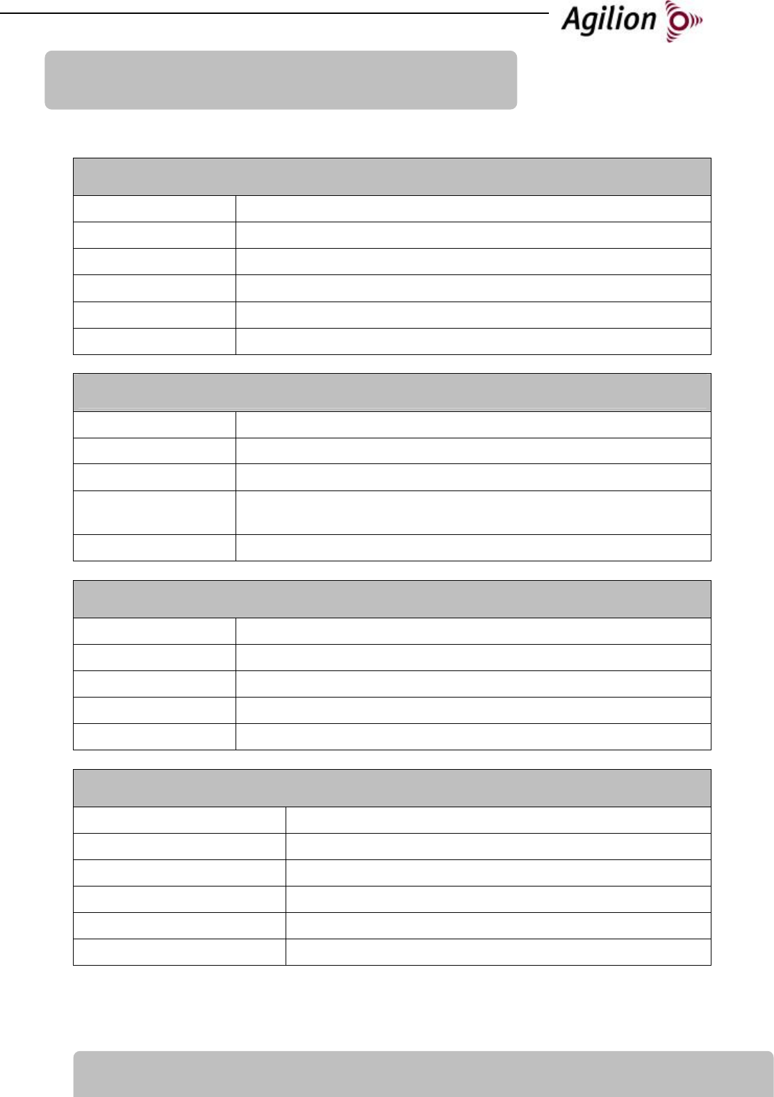
5 Technische Daten
Funk
Funkverfahren nanoLOC - Chirp Spread Spectrum (CSS)
Datenrate 1 MBit
Frequenzbereich 2,4 GHz ISM-Band
Chirp-Bandbreite 80 MHz
Sendeleistung max. 100 mW, einstellbar
Reichweite @ 1 MBit Indoor max. 90 m (typ. 60m), Outdoor max. 1.000 m (typ. 500m)
Anschlüsse und Energieversorgung
Spannung 24 V DC
Energieaufnahme max. 0,06A 1,6 W
Antennenanschluss RP-SMA-Stecker
Steckverbinder P1 8-poliger Steckverbinder WR-MPC4
0,33 mm2 bis 1,31 mm2
Sicherung Kfz-Sicherung, Mini Fuse, 5 A
Ein- und Ausgänge
Eingangsspannung 0 bis 24 V DC
Eingangsimpedanz 4,7 kOhm
Ausgang High-Side-Switch
Ausgangsstrom max. 250 mA, Kurzschlussfest
Ausgangsspannung 0 V oder Versorgungsspannung
Umgebung
Gehäuse Plastikgehäuse
IP-Schutzart IP 20, feuchtigkeitsgeschützt/coatiert
Abmessungen 138 x 62 x 31 mm
Gewicht ca. 125 g
Befestigungsmöglichkeiten 4 Befestigungslöcher für M4 Senkkopfschrauben
Temperaturbereich -40 bis +70°C

8 20130314-6021318-UM
DE
6 Konformitätserklärung
Die Agilion GmbH erklärt die Konformität von
WIRELESS TAG DRIVE
mit den Anforderungen der Normen:
EN 300328
EN 301489-17
EN 60950-1
EN 50155 (Einsatz in Bahnfahrzeugen)
EN 50121-3-2
und den EG-Richtlinien:
72/245/EEC ( – Typgenehmigung für den Einsatz in Kraftfahrzeugen)
2002/95/EC (RoHS)
Diese Erklärung gilt für alle Geräte, die das - Zeichen tragen. Bei Veränderungen an dem Pro-
dukt geht die Gültigkeit verloren.
Das WIRELESS TAG DRIVE unterliegt der 2002/96/EC und muss getrennt vom Hausmüll bei den
dafür vorgesehenen staatlichen Stellen entsorgt werden.
Dipl.-Inf. Sven Sieber Dipl.-Kfm.(FH) Andreas Werner
(Geschäftsführer) (Geschäftsführer)
Agilion GmbH
Blankenauer Str. 74
09113 Chemnitz
e1

Notes/Notizen:

Agilion GmbH
Blankenauer Straße 74
09113 Chemnitz
Germany
Tel.: +49 - (0)371 - 45 00 48-0
Fax.: +49 - (0)371 - 45 00 48-11
www.agilion.de
service@agilion.de
Management/Geschäftsführung:
Sven Sieber
Andreas Werner
HR B 21249 Chemnitz
USt.-IdNr.: DE236591552