AiRISTA Flow B400 Wi-Fi Location Tag User Manual B4
Ekahau Inc. Wi-Fi Location Tag B4
Contents
- 1. Manual 1
- 2. Manual 2
- 3. User Guide
User Guide
B4
Wi-Fi Badge Tag
User Guide

Ekahau, the Ekahau logo, Ekahau Site Survey, Ekahau Mobile Survey, Ekahau Location Survey,
Ekahau HeatMapper, Ekahau Engine, Ekahau RTLS Controller, Ekahau Positioning Engine,
Ekahau RTLS Controller, Ekahau Manager, Ekahau Activator, Ekahau Finder, Ekahau Vision,
Ekahau Tracker, Ekahau Logger, Ekahau T201, Ekahau T301, Ekahau NIC-54, Ekahau NIC-300,
Ekahau Client, and Ekahau Positioning Client are trademarks or registered trademarks of Ekahau.
Other product and company names may be trademarks or trade names of their respective owners.
The enclosed software contains implementations of Ekahau’s patent pending inventions.
This manual and the Ekahau software described in it are copyrighted, with all rights reserved. This
manual and the Ekahau software described in it may not be copied, except as otherwise provided
in your software license.
The contents of this document are provided “as is.” Except as may be required by applicable law,
no warranties of any kind, either express or implied, including, but not limited to, the implied war-
ranties of merchantability and fitness for a particular purpose, are made in relation to the accuracy,
reliability or contents of this document. Ekahau reserves the right to revise this document or withdraw
it at any time without prior notice.
Export of this technology may be controlled by the United States Government. Diversion contrary
to U.S. law prohibited.
Your use of the Ekahau software described in this user manual and its documentation are governed
by the terms set forth in your license agreement. Your use of this Ekahau software contrary to the
terms of this User Manual may void the warranty, if any, described in your license agreement.
Under no circumstances shall Ekahau be responsible for any loss of data or income, or any special,
incidental, punitive, consequential or indirect damages howsoever caused.
You may not use any Ekahau software or hardware products in hazardous environments (such
as operation of nuclear facilities, aircraft navigation or control, environments containing high levels
of dust, or mines) or in Life-Critical Solutions, unless you have advised Ekahau that they will be
used in a hazardous environment or in a Life-Critical Solution and Ekahau has had an opportunity
to evaluate further whether, and on what terms and conditions, the software or hardware products
may be licensed for your intended use. The term “Life-Critical Solution” means an application
software package or hardware device whose functioning or malfunctioning may result directly or
indirectly in physical injury or loss of human life.
Ekahau tags must always be used in compliance with the user environment and instructions con-
tained in the User Manual for the tags.
Copyright © Ekahau, Inc. 2000-2013. All rights reserved.

Table of Contents
1 Introduction ....................................................................................................................... 1
1.1 Software Release Level ........................................................................................... 1
1.2 Features of B4 ......................................................................................................... 1
1.3 User Interface .......................................................................................................... 2
1.4 Status Indication LEDs ............................................................................................. 2
2 Initial Activation of the Tag .............................................................................................. 5
2.1 Installing Ekahau Tag Activator 3 ............................................................................. 5
2.2 Supported Wi-Fi Adapters ........................................................................................ 5
2.3 Activation Procedure ................................................................................................ 5
2.3.1 Configuring Ekahau RTLS Controller Settings ............................................ 6
2.3.2 Configuring WLAN Settings ......................................................................... 7
2.3.3 Configuring Wi-Fi Channels in Use .............................................................. 8
2.3.4 Configuring IP Settings ................................................................................ 9
2.3.5 Activation ................................................................................................... 10
2.3.6 List of Available Settings in the Activator ................................................... 14
3 Configuration After Initial Activation ............................................................................ 17
3.1 Tag Configuration Settings in ERC Configs Page .................................................. 17
3.2 Tag Actions Available in ERC Tags Properties Page ............................................. 19
4 Tag Operation ................................................................................................................. 21
4.1 Button Activated Location Update and Maintenance Call ...................................... 21
4.2 Safety Switch Activated Location Update .............................................................. 21
4.3 Working with the Display ........................................................................................ 21
4.3.1 Instant Messages ....................................................................................... 22
4.3.2 Standard Messages ................................................................................... 22
4.4 Load Balance ......................................................................................................... 23
4.5 Smart Roaming ...................................................................................................... 23
4.6 Resetting to Factory Settings ................................................................................. 23
4.7 Firmware Update ................................................................................................... 24
4.8 Optimizing Battery Life ........................................................................................... 24
4.9 Turning off the B4 Tag ............................................................................................ 25
4.10 Charging the B4 tag ............................................................................................. 25
5 Technical Specifications ................................................................................................ 27
5.1 General .................................................................................................................. 27
5.2 Wi-Fi ....................................................................................................................... 27
5.3 Operating Ranges from an Access Point ............................................................... 27
5.4 Care and Maintenance ........................................................................................... 27
6 Certifications .................................................................................................................. 29
6.1 FCC Rules ............................................................................................................. 29
6.1.1 FCC RF Radiation Exposure Statement .................................................... 29
6.1.2 Réglementations FCC ............................................................................... 29
6.2 Industry Canada Statements for Portable Devices ................................................ 30
7 Limited Warranty ............................................................................................................ 31
B4
iii

B4
iv

1 Introduction
Introduction The Ekahau B4 Wi-Fi tag is part of Ekahau RTLS (Ekahau Real-Time Location System)
that consists of Ekahau wi-fi tags, 5.x (ERC) software platform and Ekahau Vision (1.7 or 2.0) end-
user application. The B4 tags are primarily targeted to be carried by people, but can be attached
to any mobile object or asset as well. The Ekahau RTLS Controller software continuously reports
the tag's location information such as coordinates and logical areas within the Wi-Fi coverage area
both indoors and outdoors.
1.1 Software Release Level
This User Guide documents the functionality available with software release level 1.0 onwards.
1.2 Features of B4
The following features are included with this software release:
● Works with standard 802.11b, 802.11g, and 802.11n Wi-Fi networks at 2.4GHz frequency
band.
● Support for 64 or 128-bit WEP key and WPA2-PSK authentication.
● Supports also access point load balance.
● Static and dynamic IP addressing.
● Safety switch for triggering an alarm.
● Three configurable buttons for sending and acknowledging alarms, and resetting the tag to
its factory settings.
● Location reporting triggered by button, periodic timer, motion or safety switch.
● Two status indication LEDs for determining the tag status.
● A buzzer for audible alarms and notifications.
● An OLED (organic LED) display for receiving messages
● Configuration using Ekahau Tag Activator 3, standalone tag configuration software.
● Configuration using Ekahau RTLS Controller
Chapter 1. Introduction
1
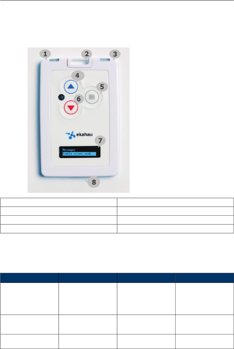
1.3 User Interface
5. Menu Button1. Left LED
6. Red Button2. Safety Switch
7. Display3. Right LED
8. Charging Port4. Blue Button
1.4 Status Indication LEDs
The tag is equipped with two multi-color LEDs that provide status indication. The table below lists
the different modes of the tag LEDs:
StatusRight LEDLeft LEDAction
Both LEDs blink Red after
button press. . Finally Left
LED blinks green or red.
Green indicates successful
activation
1xRed1xRed
2xGreen
2xRed
Activation. Press and hold
the Menu button for 3
seconds
Charging
Battery full
Orange
Green
-Charging
Successful scan and res-
ults sent to ERC
-2xGreen blinkPeriodic or motion activ-
ated scan
2
Chapter 1. Introduction

StatusRight LEDLeft LEDAction
Failed to scan or send
results
-2xRed blinkPeriodic or motion activ-
ated scan
Success - green
Failed to scan or send
results - red
-1xOrange + 2xGreen blink
or
2xRed blink
Blue button press
Success - green
Failed to scan or send
results - red
1xOrange + 2xGreen blink
or
2xRed blink
Red button press
Success - green
Failed to scan or send
results - red
1xOrange + 2xGreen blink
or
2xRed blink
Menu button press
After completing the
sequence erases all config-
urations from tag's
memory and shows
"Deactivate" message in
the display
5 sec green when reset
sequence is possible
1xOrange
1xOrange
1xOrange
Reset. Put tag in charger.
Remove from charger and
within 5 seconds press
and hold Blue button down
until Right LED blinks
orange, then immediately
release the Blue button
and press Red button but-
ton until both LEDs blink
2xGreen blinkSuccessfully sent scan
results (Not dependent on
scan reason)
2XRed blinkUnsuccesfully sent scan
results
Chapter 1. Introduction
3

4
Chapter 1. Introduction

2 Initial Activation of the Tag
When the tag is delivered it does not have any of the necessary configuration settings. These
environment specific settings need to be applied before the tag can connect to the network and
the ERC. The B4 tags are delivered with the battery charged to a storage charge, it is recommended
to fully charge the battery, before activating the tags first time. See charging instructions in chapter
Charging the B4 tag on page 25.
Tag activation is done using Ekahau Activator software that configures Ekahau tags wirelessly.
The activation of the tags is explained in more details in chapter Installing Ekahau Tag Activator
3 on page 5.
After successful Activation you will see the MAC address of the tag appears on the ERC list of
tags. After successful connection with ERC the configurations can be managed directly from ERC
using Tag Configurations page.
2.1 Installing Ekahau Tag Activator 3
The Ekahau Tag Activator 3 comes with the Ekahau RTLS installer. When you install Ekahau
RTLS, you do not necessarily need to install the Ekahau Activator if the target computer cannot
be used to activate tags with a supported Wi-Fi adapter. If you want to install the Ekahau Activator
later on another computer, simply run the RTLS setup file on the target computer and choose to
install only the Ekahau Activator. The Ekahau Activator is usually installed on a laptop as the
Ekahau RTLS software is installed on a server.
The Ekahau Tag Activator 3 installation package can also be downloaded from http://www.eka-
hau.com/download/activator.
How to install Ekahau Activator:
1. Choose a laptop (or a desktop) computer running Windows 7 (32 or 64bit operating system)
with a supported Wi-Fi adapter (and driver supporting virtual Wi-Fi), at least 256 MB of memory,
free USB port, and 3.5 MB or more free hard disk space.
2. Run the Ekahau Activator setup file from it's location, and follow the on-screen instructions
3. Install a supported Wi-Fi adapter from th eprograms menu: Start -> Ekahau -> Ekahau Tag
Activator 3 -> Ekahau USB Driver.
2.2 Supported Wi-Fi Adapters
Please visit our website for the complete list of supported Wi-Fi adapters: http://www.eka-
hau.com/devices.
2.3 Activation Procedure
For the tags to be able to communicate with the Ekahau RTLS Controller, the tag needs to be
activated e.g. the tag needs to be given the necessary parameter to associate with the network.
At least the IP address of the Ekahau RTLS Controller, SSID of the network used and the IP
configuration method are required. To activate B4 tags, you need to use the Ekahau Tag Activator
Chapter 2. Initial Activation of the Tag
5
3 which you can run from Ekahau Programs menu. After that, follow the following Activator config-
uration procedure.
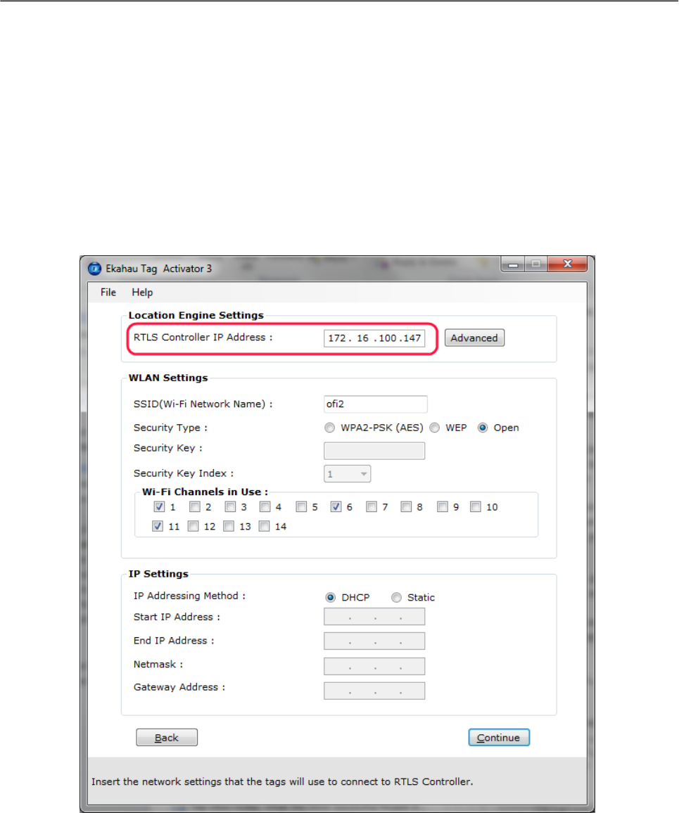
2.3.1 Configuring Ekahau RTLS Controller Settings
Input the IP address of the Ekahau RTLS Controller.
Figure 2.1. Specifying the Engine IP address and Maintenance interval
In case Engine Port, Maintenance port, and/or Maintenance IP needs to be changed, go to
"Advanced" mode. The (Periodic) Location Update Interval is set to 60 seconds and the (Periodic)
Maintenance Interval is set to 240 seconds by default , but shorter interval can be used if, for
instance, messages are sent frequently to the B4 tag.
6
Chapter 2. Initial Activation of the Tag
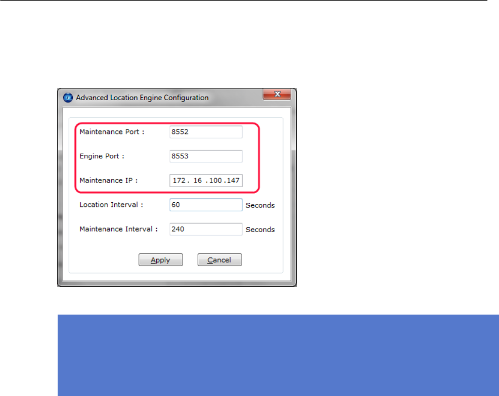
Figure 2.2. Specifying advanced Positioning Engine settings
Note
When activating the B4 tags, only an initial setup is required for the tag to associate with the
network. All settings can be set and changed from the Ekahau RTLS Controller. Ekahau Tag
Activator 3 only provides a set of basic settings.
2.3.2 Configuring WLAN Settings
Input the Wi-Fi Network SSID and select the Encryption method used. If WEP 64/128 or WPA2-
PSK is used type in the network key as well. Normally, 1st Security Key Index (for WEP encrytion)
is used. Should you use key index other than the first one, please select the key index matching
the Security Key.
Chapter 2. Initial Activation of the Tag
7
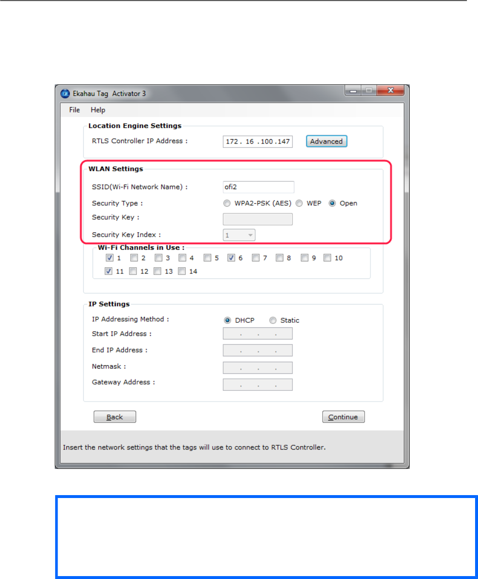
Figure 2.3. Specifying Wi-Fi network settings
Tip
If WEP encryption is used the Activator automatically determines the key type and length from
what you type. WEP 64 require 5 Ascii characters or 10 hex digits, respectively WEP 128
requires 13 Ascii characters or 26 hex digits.
2.3.3 Configuring Wi-Fi Channels in Use
It is recommended to only select the channels used in you network. Activating the unused channels
will only reduce the battery lifetime of the tag. By default, the Scan Interval is 60 seconds. You
may also use shorter interval, but it will drain faster the battery of the tag. Alternatively you can
use longer Scan Interval and enable Motion Sensor through the Ekahau RTLS Controller after
activation. This way the tag will scan only when it is in use and moving.
8
Chapter 2. Initial Activation of the Tag
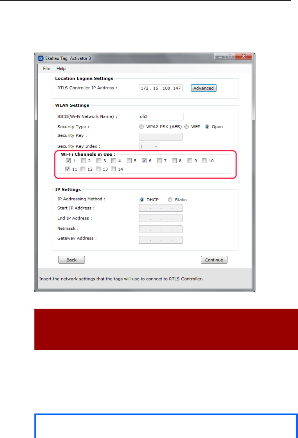
Figure 2.4. Specifying the channels used in the network
Warning
Only use channels that really exists in you Wi-Fi network. Activating unnecessary channels will
reduce the tag's battery lifetime!
2.3.4 Configuring IP Settings
Check the IP settings. If DHCP is used nothing needs to be done. In case your network uses static
IP addressing, type in the IP address range to be used for the B4 tags, Netmask and Gateway
addresses.
Tip
Chapter 2. Initial Activation of the Tag
9
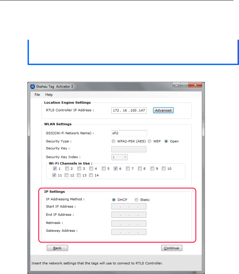
If you only activate a single tag and wish to use static IP setting, enter same IP address in
'Start IP Address' and 'End IP Address'.
Figure 2.5. Specifying IP settings
2.3.5 Activation
Press 'Continue' button when all settings are ready.
10
Chapter 2. Initial Activation of the Tag
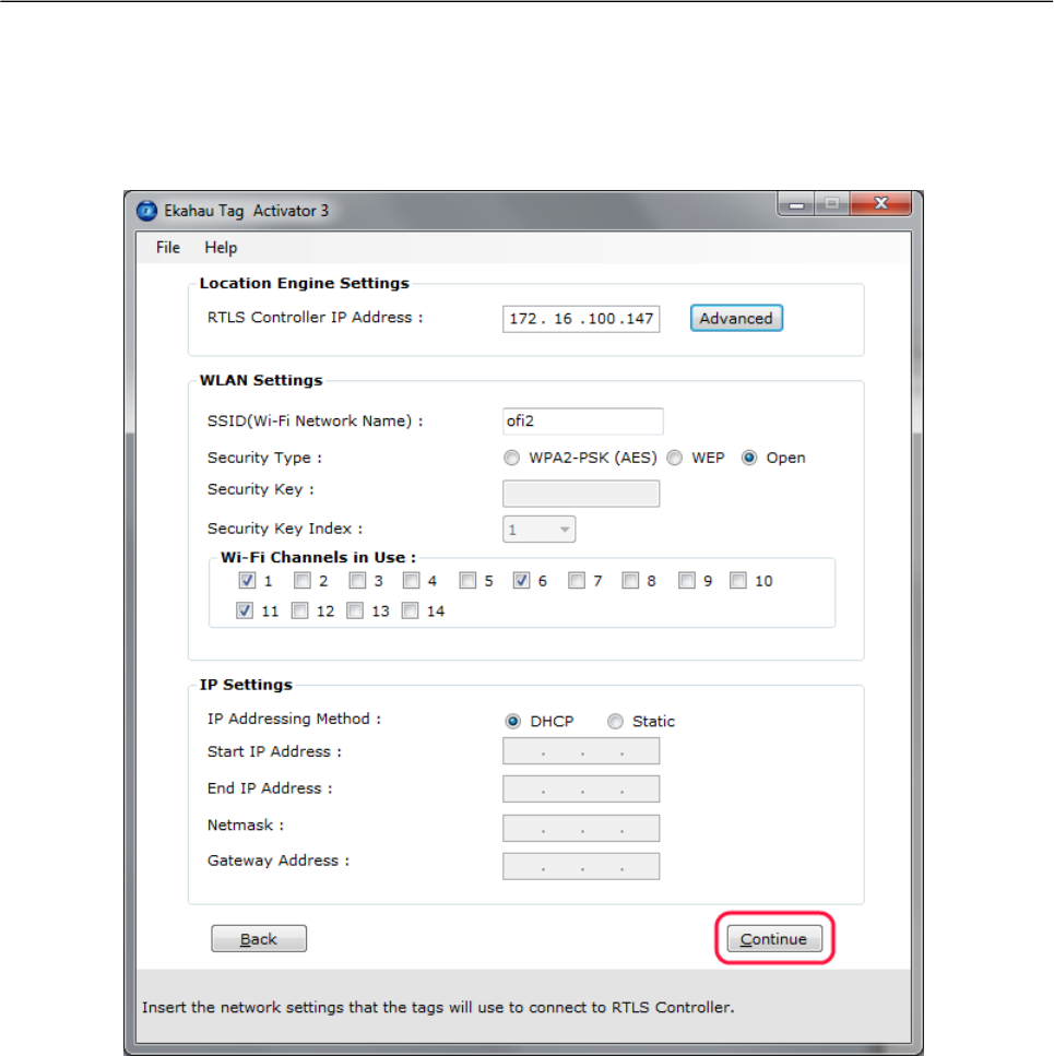
Figure 2.6. When all the settings are done, you can start activating the tags
The Activation process is now started. The list of the activated tags will appead on the area below.
Chapter 2. Initial Activation of the Tag
11
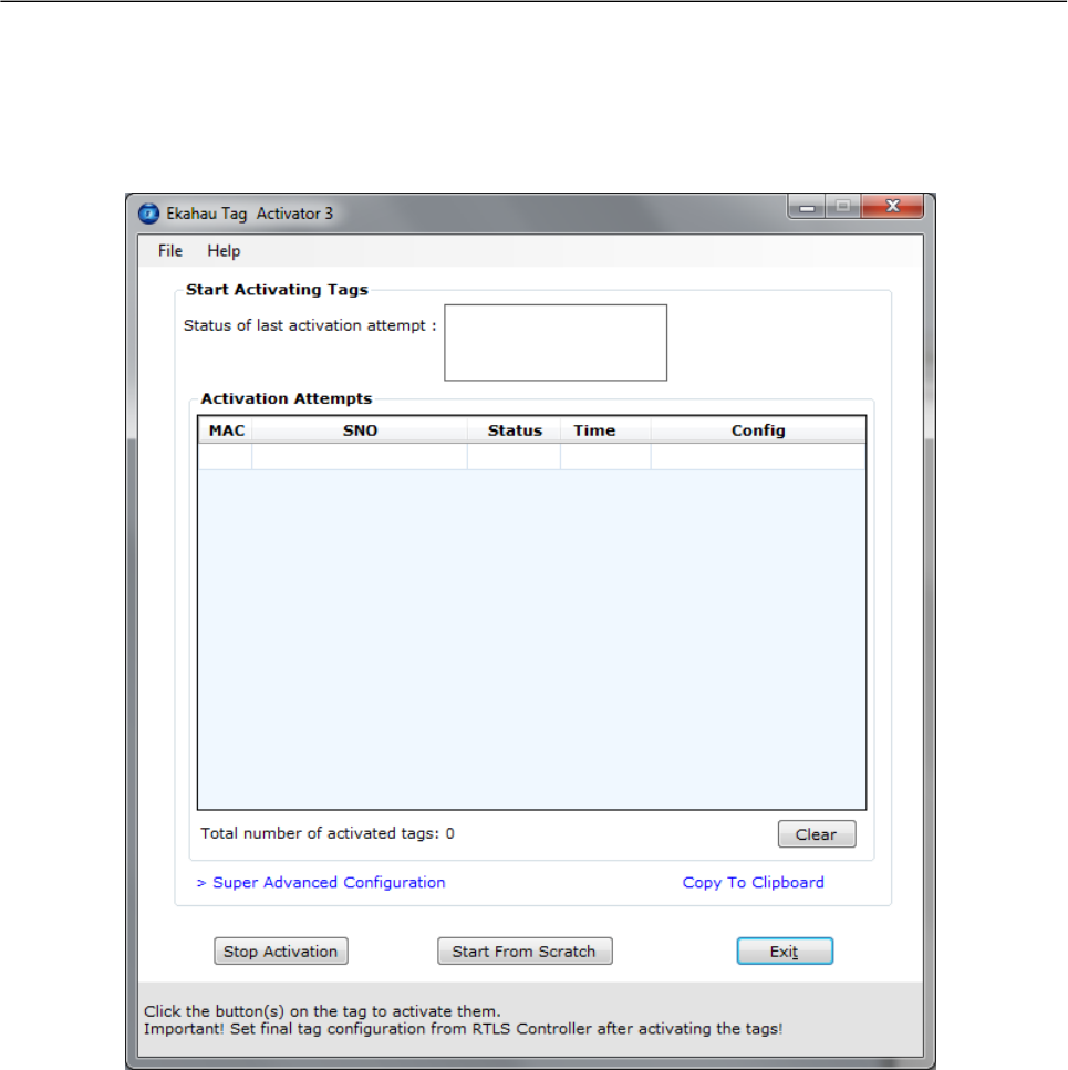
Figure 2.7. The Activator is ready to start activating the tags
Press the tag's Menu button to activate it. After successful activation, the tag MAC address appears
on the activation window, showing Ok status. Repeat this for all the tags to be activated.
12
Chapter 2. Initial Activation of the Tag
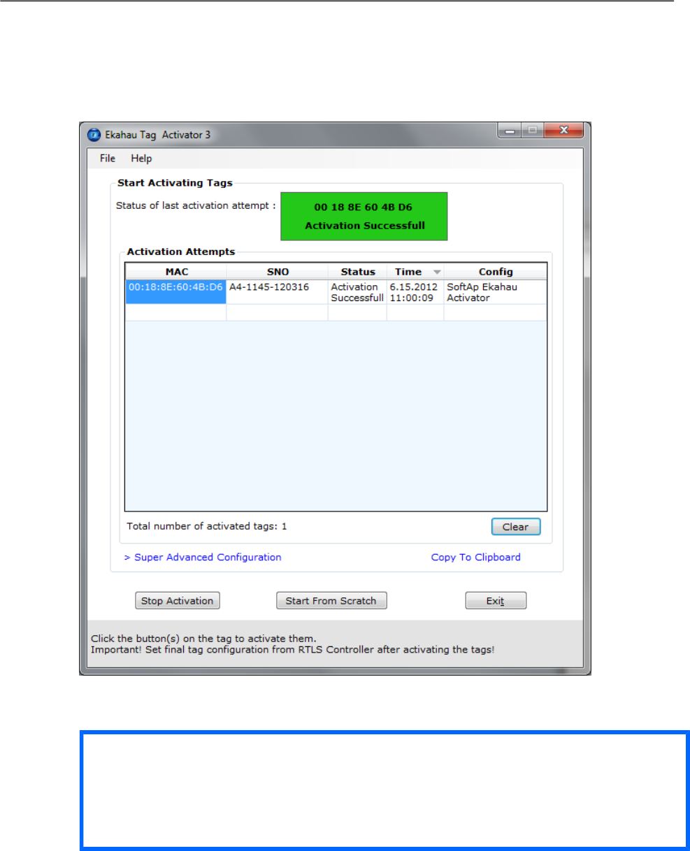
Figure 2.8. The Activator has activated one tag
After completing activating the tags, click the 'Stop Activation' button and exit the activation window.
Tip
After you have finished the activation, you can save the configuration for future use from the
file menu. If you save the settings with 'Save As Default' the setup will be the default every
time the Activator is started.
Chapter 2. Initial Activation of the Tag
13
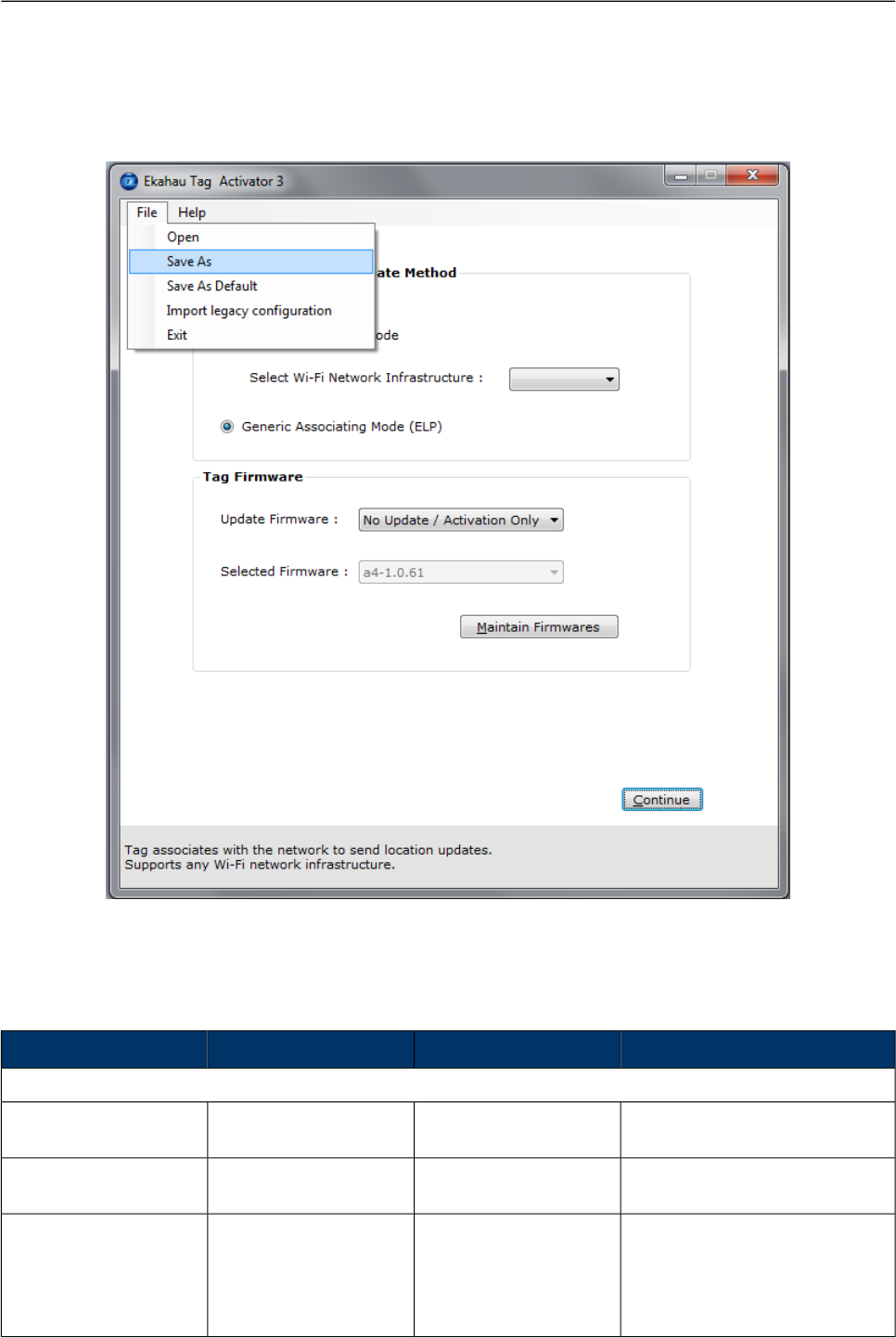
Figure 2.9. Saving the configuration for later use
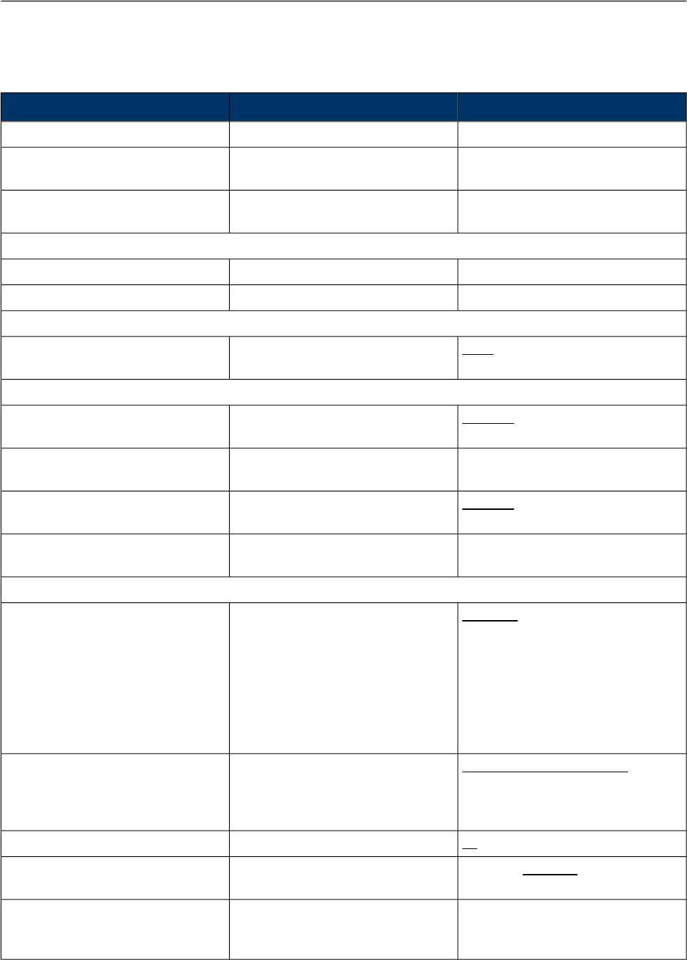
2.3.6 List of Available Settings in the Activator
The list of available settings in the Activator:
Default valueValuesDescriptionSetting
Positioning Engine settings
0.0.0.0IP AddressIP Address Ekahau
RTLS Controller
Engine IP
8552Port numberPort number of location
protocol port of ERC
Engine Port (UDP)
0.0.0.0IP AddressIP Address of Ekahau
RTLS Controller, from
where TAG gets the set-
tings. Typically same as
the ERC IP
Maintenance IP
14
Chapter 2. Initial Activation of the Tag

Default valueValuesDescriptionSetting
8553Port numberPort number of mainten-
ance protocol port of
ERC
Maintenance port (UDP)
100 - 63072000The interval of the peri-
odic maintenance calls
in seconds
Maintenance interval
Scan Settings
100 - 63072000The interval of the peri-
odic location scans in
seconds
Scanning Interval
1 - 11 Enabled; 12 - 14 DisabledEnabled; DisabledSets the channels that
are scanned
Scan Channels
WLAN Settings
defaultSSID=max 32 digitsSets the Wi-Fi network
name -Service set identi-
fier
SSID
No EncryptionNo Encryption; WEP
64/128; WPA2-PSK
Selects if WEP encryp-
tion is used
Encryption
-ASCII: 5 or 13 charac-
ters
HEX: 10 or 26 hexa-
decimal numbers (0-f)
Sets the WEP pass-
phrase
WEP
11 - 4Sets the WEP Key index
used
WEP Key Index
-8 - 63 ASCII charactersSets the WPA2-PSK
encryption and pass-
phrase
WPA2-PSK
Not supported in B4WPA-PSK
IP Settings
DHCPDHCP; StaticDefines the IP address
assigning method
IP method
Static IP Settings
0.0.0.0
0.0.0.0
IP addressSets the start and end
address of the range
used to assign the IP
addresses to the tags
when Static IP is used
Address range
0.0.0.0IP addressTag netmask when
static addressing is used
Network mask
0.0.0.0IP addressIP network gateway
when static addressing
is used
IP gateway
Chapter 2. Initial Activation of the Tag
15

16
Chapter 2. Initial Activation of the Tag

3 Configuration After Initial Activation
The tag can be adjusted for each application and network settings by adjusting a set of parameters.
The parameters can be changed wirelessly after resetting the tag by using the Ekahau Activator
software or through Tag Configurations in Ekahau RTLS Controller.
Ekahau Activator is used for configuring the initial configuration settings that allows connecting
the tag to ERC over the network. After connection is established with ERC, all configurations can
be managed through Ekahau RTLS Controller.
3.1 Tag Configuration Settings in ERC Configs Page
In Ekahau RTLS Controller it is possible to create a configuration to a single tag or a group config-
uration to multiple tags. After the tags are activated, the configurations are applied to tags from
the Tags page. It is also possible to apply a configuration automatically to all new tags via the
Configs page. The list of available settings is in the following table:
Values (Default underlined)DescriptionSetting
Network
Generic, Aerohive, Aruba, Cisco
CCX, Extricom, Meru, Motorola,
Juniper Blink
Allows using a vendor-specific
method for signal measurement.
The Generic method is vendor
independent
Scan Method
Can be set based on scan reason(s)
(buttons, safety switch, motion...)
Allows location updates sent via
CCX/Ekahau Blink and button
presses, etc. sent via ELP.
CHOOSE button shows the options.
Recommended not use Mixed Mode
with Cisco MSE (or battery reporting
will be mixed up)
ELP Mixed Mode Flags
See Configuring WLAN Set-
tings on page 7 for details
SSID 1 name, Encryption, Pass-
phrase and WEP index
SSID 1
See Configuring WLAN Set-
tings on page 7 for details
SSID 2 name, Encryption, Pass-
phrase and WEP index
SSID 2
No association and scan only;
associate and scan; Disabled
Sets whether tag attempts to asso-
ciate on B4 SSID 2 network
SSID 2 Association
Enabled; DisabledSets whether the tag uses broad-
cast probe when scanning
Broadcast probe
Tag IP Settings
Use DHCP for each access point
Use DHCP once for all access
points
Preserve the IP-address that was
given by Activator
Sets the IP method usedIP Setting
Positioning Engine
Chapter 3. Configuration After Initial
Activation
17
Values (Default underlined)DescriptionSetting
IP AddressSets the ERC IP AddressIP Address
Port numberPort number of location protocol port
of ERC
Location update Port (UDP)
Port numberPort number of maintenance pro-
tocol port of EPE
Maintenance port (UDP)
General
Free textName for the configuration setName
Free textDescription for the configuration setDescription
Channels
1- 11; 12 (EU); 13 (EU); 14 (Japan)Sets the channels scanned during
a location scan
Scan Channels
Periodic Location Update and Maintenance
Enabled; DisabledEnables or disables the periodic
location update
Periodic Location Update
The interval in Seconds, Minutes,
Hours or Days
Sets the interval for the periodic
location update
Location Update Interval
Enabled; DisabledEnables or disables the periodic
maintenance calls
Periodic Maintenance
The interval in Seconds, Minutes,
Hours or Days
The interval of the periodic mainten-
ance calls in seconds
Maintenance Interval
Sensors
Disabled
Profile 1 (in motion for 8s)
Profile 2 (in motion for 4s)
Profile 3 (in motion for 2s)
Profile 4 (in motion for 1s)
Enables or disables motion sensorsMotion Sensor
In-motion and after motion; After
motion
Sets whether location updates are
sent periodically during the motion
or just when the motion starts and
after the movement has ended
Motion Update Method
5s; 10s; 30s; 1min; 2min; 5minSets the interval for motion updatesMotion Update Interval
Enabled; DisabledEnables or disables stagnant sens-
ing
Motion Stagnant Event
The threshold in Seconds, Minutes,
Hours or Days
Sets how long the tag has to remain
stagnant to produce a stagnant
event
Motion Stagnant Treshold
18
Chapter 3. Configuration After Initial
Activation

Values (Default underlined)DescriptionSetting
Disabled, Passive Mode, Active
Mode
Enable or disable the location
beacon sensor. In active mode a
location update is done immediately
when the tag notices a location
beacon. In passive mode the recent
observed location beacon ID is sent
to ERC only when location update
is initiated by other stimuli such as
periodic or motion wakeup
Location Beacon Sensor
Advanced scan settings
1 - 10Number of scans the tag does on
each triggered scan despite the
triggering event. Used to improve
the accuracy in difficult conditions
and for rarely scanning applications
Initial Scan Count
No Delay; 250ms; 500ms; 1000ms;
1500ms; 2000ms
Delay between the scansDelay between initial scans
0 - 10The number of scans the tag per-
forms for each after motion event
After Motion Scan Count
0 - 10The number of scans the tag per-
forms for each button event
Button Scan Count
Note
Network wide DHCP enables roaming between subnetworks. With this setting the tag refreshes
its IP address whenever the tag associates with a new access point. It is not recommended to
use the feature, if not required, due to higher power consumption.
Note
Using the Advanced Scan Settings needs a careful consideration. The scanning consumes
a high amount of energy, and the more scanning is done the less battery life the tag has. Typ-
ically these parameters are used to improve accuracy in very difficult conditions or in cases the
tag otherwise would scan rarely.
3.2 Tag Actions Available in ERC Tags Properties Page
ValuesDescriptionSetting
User Data
Free textA user given name for tagName
Free textA custom noteCustom
Chapter 3. Configuration After Initial
Activation
19

ValuesDescriptionSetting
List of groups or "No Groups cre-
ated" if no groups exist. Go to
groups page to create groups
The groups the tag belong toMember of Groups
Commands
LED; LED and Buzzer
Duration: 10s; 1min; 10min; 30min;
1h; 2h
Launches the alarm at the tag with
LEDs and buzzer or silently with
LEDs only. The alarm duration can
be set
LED / Buzzer
-Manual command or a list of com-
mands can be sent to a tag
Manual Commands
A list of available configs. Go to
configs page to create tag configur-
ations
A pre defined config can be selected
and sent to tag(s)
Set Config
Firmware Update
A list of available firmware updates
uploaded in ERC. The firmware
needs first to be uploaded into ERC,
this is done in configs page
Tag firmware can be updated. The
new firmware needs to be first
uploaded in the configs page
Firmware
Create New Group
Free textNew group is created and the tag is
included into this created group
Group Name
Manual IP Settings
IP AddressSets the tag IP AddressManual IP address
IP AddressSets the tag netmaskNetmask
IP AddressSets the default gateway for the tagGateway
Delete
-The tag is deleted from the system.
All statistics are cleared. The tag will
appear in the system again when it
report it's location next time
Delete
20
Chapter 3. Configuration After Initial
Activation
4 Tag Operation
4.1 Button Activated Location Update and Maintenance
Call
In addition to periodic location updates, the tag can also be set to scan and update it's location
when any of the buttons is pressed. After a button press the tag scans and sends the RSSI results
to ERC immediately. If the Blue button was pressed the TAG will additionally do a maintenance
call to update the settings and to read queued LED/Buzzer alerts and messages. The LEDs
indicate the scan success or failure similarly as in the scan activated by the wake up interval. It is
also possible to define button press based events with Ekahau Vision such as alarms. For more
information, please refer to Ekahau Vision user guide.
Ekahau RTLS Controller recognizes the B4 tag's button presses as different scan reasons:
● Red button corresponds "scanreason 1 = Button"
● Blue button corresponds "scanreason 6 = Button2"
● Menu button corresponds "scanreason 8 = Button3"
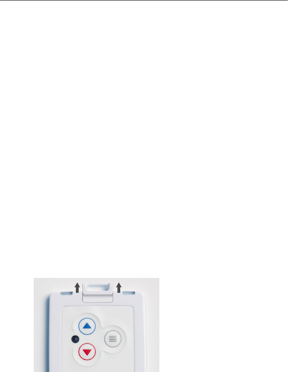
4.2 Safety Switch Activated Location Update
If the safety switch is pulled out from it's original position, the tag will update it's location to the
ERC with the Safety Switch flag. If the location update is not succesful, the tag will retry until the
succesful update. The Safety Switch can be used to send alerts to personnel via Ekahau Vision
when the switch is pulled out. It is advised to keep the safety switch pulled out while the situation
is in progress to avoid the accidental cancellation of the alert. For more information, please refer
to Ekahau Vision user guide.
Figure 4.1. Safety switch operation
4.3 Working with the Display
The B4 tag's OLED display can be used to read messages sent from Ekahau Vision and Ekahau
RTLS Controller. The B4 reads the queued messages during maintenance updates which are
made at regular intervals defined by the maintenance interval or when the Red button is pressed.
Chapter 4. Tag Operation
21
Thus, if the maintenance interval is 60 seconds, the tag can read the new messages every 60
seconds. This needs to be kept in mind if urgent messages need to be sent to the tag. When the
tag receives a new message, a small notification sound is played.
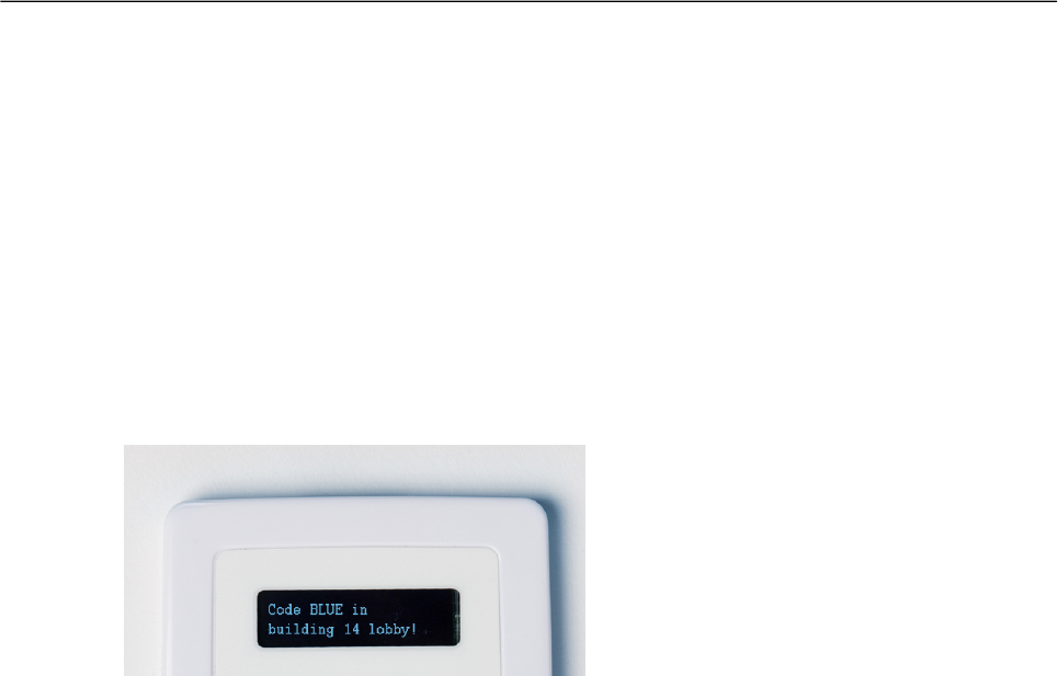
It is possible to send 160 character long instant messages and standard messages to the B4 tag.
In Ekahau Vision the message size is limited to 40 characters as the message includes additional
location information. The maximum number of messages that can be saved to the tags memory
depends on the length of the messages. For example, the tag can save 9 messages that are 100
character long and 15 messages with 50 characters.
Figure 4.2. An example message
4.3.1 Instant Messages
As the name implies, an instant message is displayed at the display right away. If the instant
message was sent by a triggered event, the tag will also display the zone where the event was
triggered. To exit from the instant message, press and hold the Menu button. Note that in contrast
to the standard messages, instant messages will not be saved to the tag's memory and will be
replaced by another incoming instant message.
4.3.2 Standard Messages
When a standard message is received, a "Message pending" is displayed. To read the standard
message:
1. Press and hold the Menu button to access the tag's Messages menu
2. By default, the selector is automatically over the latest message, now simply press the Menu
button to read the message
There is two ways to exit from the Message reading screen:
● Press the Menu button to either delete the message or to go back to Messages menu where
you can read all the messages in the tag
● Press and hold the Menu button to exit from the tag's menus
You can read the saved standard messages as follows:
1. Press and hold the Menu button to enter the tag's Main menu
2. Browse to Messages menu with the Blue or Red button and press the Menu button to enter
3. Use Blue or Red button to browse to the message you want to read and press the Menu
button to read it
To delete a standard message, follow the instruction explained above to first access the message
reading screen and then do following:
22
Chapter 4. Tag Operation
1. Press the Menu button
2. Browse to Delete and press the Menu button to delete the message
3. After the delete, you will get back to the Messages menu where you can continue reading/delet-
ing messages or go back to the Main menu
Note
You can exit from the tag's menus whenever by pressing and holding the Menu button.
Tip
You can disable the tag's buzzer by entering the Main menu and selecting Enable silent
mode.
Tip
For more information on how to send messages to the B4 tag, please refer to Ekahau Vision
and Ekahau RTLS Controller User Guides.
4.4 Load Balance
The B4 tag supports access point load balance from firmware 1.2.0 onwards. Should the nearest
(strongest) access point reject tag association attempt because of the limit of simultaneous client
associations is reached, tag automatically searches the second strongest access point in the
network and associates to it. In case the second strongest access point is also unavailable (because
of the maximum number of simultaneous clients is reached there too), tag will continue searching
the third strongest for connection.
4.5 Smart Roaming
Normally tag stays associated to the same access point until the connection is almost lost. The
EkahauB4 tag (from firmware 1.2.0 onwards) keeps track of the signal strengths of the access
points. In case an access point with signal strenght stronger than 10 dBm or more than the one
tag is currently associated is found (from the same network), tag automatically switches to that
access point.
4.6 Resetting to Factory Settings
The tag can be reset to factory setting with the following button sequence . Note that you need to
connect the tag to the charger first to enable the reset sequence. Tag can be removed from the
charger, but the reset sequence must be initiated within 5 seconds after removal. During this time
tag will show continuos green light on the right LED.
Chapter 4. Tag Operation
23

1. Press and hold the Blue button until Right LED flashes orange. If the tag is busy this may take
even 20 seconds.
2. Then immediately release the Blue button button and press down the Red button .
3. After approximately 2 seconds both LED’s flash orange. If the tag is busy, it may flash only
the Right LED.
4. The tag has now been reset to factory settings. The tag is in reset mode when it does not
execute button scan as defined in section Button Activated Location Update and Maintenance
Call on page 21 and pressing the Menu button does not turn on the display.
Note
Resetting the tag to factory settings removes all messages from its memory!
4.7 Firmware Update
The tag firmware can be updated wirelessly using ERC. The firmware is uploaded to the tags from
the Tag Properties page or directly from Tags page in ERC. Follow instruction in the ERC User
Guide for updating the firmware.
Note
If the Tag battery level is below 50% - or below 10% when in charging - the FW update is not
allowed. The corresponding error code in ERC is TU. To update the firmware, please first
recharge the battery and try again.
4.8 Optimizing Battery Life
The B4 Wi-Fi tag uses an ultra-low power system-on-chip architecture that lowers the power
consumption to minimal, but to ensure optimal performance with targeted lifetime, here are some
considerations.
The principal in optimizing battery life is to determine the maximum interval for location updates,
still sufficient for the use case, to minimize the amount of time the tag is active.
Recommendations for optimizing battery lifetime:
● Scan only channels that are in use in your network. Typically, because of overlap of channels,
there are only 3 or 4 channels in use from the 11 (or 13/14) available.
● Use single SSID whenever possible. Using multiple SSIDs requires additional network scans
and decreases battery lifetime.
● When using dynamic IP addressing tune the DHCP server to provide very long lease times
for tags.
● The tag supports roaming between subnetworks. This feature renews tag’s IP address
whenever the access point association changes. Since renewing IP addresses consumes
large amounts of energy, it is strongly recommended not to use the network wide dynamic
addressing feature if it is not needed.
● Tune the wake up settings to match your application needs. More frequent updates lower the
battery lifetime.
24
Chapter 4. Tag Operation
Tip
The battery level can be checked by briefly pressing the Menu button. The text
will disappear automatically in a few seconds.
4.9 Turning off the B4 Tag
The B4 tag can only be turned off by resetting the tag to factory settings which is explained in
chapter Resetting to Factory Settings on page 23. To continue using the tag after resetting, you
have to re-activate it following the instructions explained in chapter Activation Procedure on page 5.
Note
Turning off the tag's display by exiting from the tag's menus, will not turn off the tag! The tag
will stay operational until it is reset to factory settings.
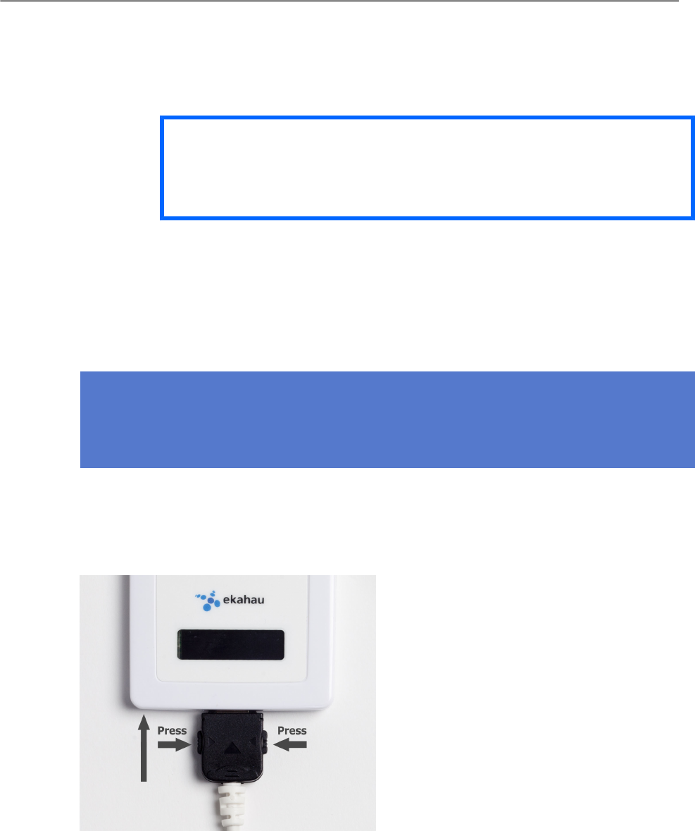
4.10 Charging the B4 tag
Figure 4.3. Connecting the tag with a Single Charger
Chapter 4. Tag Operation
25

Figure 4.4. B4 tags in Multi Charger
The B4 tag is delivered with the battery charged to a storage charge, and it is recommended to
fully charge the batteries before first time activating the tag. To ensure the tag battery is full, please
put the tag in to a charger for 4 hours. To remove the charger plug, release the plug by pressing
the latches on the plug and pull the plug out.
The tag will give a notification when the tag battery is low. Connect the charger and the Right LED
will show orange light during the charging. after the tag is fully charged the Right LED will turn
green. If the tag battery is completely empty, the tag will automatically turn off. After a charger is
connected, the tag will automatically return to it's normal function, maintaining last settings.
The Ekahau supported adapters are
1. Ekahau C-T301B Charger
2. Ekahau C301B-10 Multi Charger
Note
In case the tag battery is completely empty, typically when left empty and uncharged for several
days, it may take a long time for the tag even to turn on the orange led. Just connect the charger
and leave the tag to recharge overnight.
Warning
Only use Ekahau supported adapters for charging the tags.
Warning
Recharge the tag only in room temperature conditions, 0 °C - 40°C (32 °F - 104 °F). Recharging
the tag in too cold or too hot conditions may damage the tag.
26
Chapter 4. Tag Operation

5 Technical Specifications
5.1 General
● Outside Dimensions : 2.36 x 3.54 x 0.33 in / 60 x 90 x 8.5 mm.
● Weight: 1.6 oz / 46 g
● Power: Re-chargeable Lithium Polymer battery
● Charging with 5 VDC, 500 mA max.
● Three buttons with call button functionality
● Two red/green/orange status indication LEDs
● Organic LED display
● Operating Temperature: 32 to 122 ºF / 0 to 50 ºC, battery lifetime is lower on the low and high
end of the temperature range.
● Storage Temperature: -40 to 140 ºF / -40 to 60 ºC, battery lifetime is lower on the low and
high end of the range. Storage in room temperature is recommended.
● Humidity: From 20 % to 95 % non-condensing, relative humidity
● Environmental Protection: Protected against dust and spraying water
5.2 Wi-Fi
● Supported IEEE Standards: 802.11b/g
● Modulation Scheme: Direct Sequence Spread Spectrum (DSSS)
● Media Access: CSMA/CA
● Transmit Power: +12 dBm@2Mbps
● Receiver Sensitivity: -93 dBm@1Mbps
● Frequency Ranges:
○ 2.400 - 2.4835 GHz (USA, Canada, Europe)
○ 2.400 - 2.497 GHz (Japan)
● Supported Networking Protocols: UDP/IP, DHCP or static addressing
● Security: WEP Encryption 40/104 Bit, WPA2-PSK
● Antenna Type: Internal omni-directional ceramic multilayer
● Maximum Antenna Gain: 0 dBi
5.3 Operating Ranges from an Access Point
● Open Space: 100m (330 ft)
● Typical Office: 40m (130 ft)
5.4 Care and Maintenance
● Keep the tag dry. Precipitation, humidity and all types of liquids or moisture can contain min-
erals that will corrode electronic circuits.
● Do not use or store the tag in dusty, dirty areas. Its moving parts can be damaged.
● Do not store the tag in hot areas. High temperatures can shorten the life of electronic devices,
damage batteries, and warp or melt certain plastics.
● Do not store the tag in cold areas. When it warms up (to its normal temperature), moisture
can form inside, which may damage electronic circuit boards.
● The operating temperature of the tag is 0 to 50 ºC (32 - 122 ºF). Do not operate the tag outside
this temperature range.
Chapter 5. Technical Specifications
27

● Do not try to open the tag.
● Do not drop, knock or shake the tag. Rough handling can break internal circuit boards.
● Do not use harsh chemicals, cleaning solvents, or strong detergents to clean the tag.
● Do not paint the tag. Paint can clog the moving parts, affect the radio communication and
prevent proper operation.
● Use a soft, clean and dry cloth to clean the tag.
● Use only the supplied antenna. Unauthorized antennas, modifications or attachments could
damage the tag and may violate regulations governing radio devices.
28
Chapter 5. Technical Specifications

6 Certifications
6.1 FCC Rules
This device complies with Part 15 of the FCC Rules. Operation is subject to the following two
conditions:
(1) this device may not cause harmful interference, and
(2) this device must accept any interference received, including interference that may cause
undesired operation.
FCC ID of this device is: TA7-B400
This equipment has been tested and found to comply with the limits for a Class B digital device,
pursuant to part 15 of the FCC Rules. These limits are designed to provide reasonable protection
against harmful interference in a residential installation. This equipment generates uses and can
radiate radio frequency energy and, if not installed and used in accordance with the instructions,
may cause harmful interference to radio communications. However, there is no guarantee that
interference will not occur in a particular installation. If this equipment does cause harmful interfer-
ence to radio or television reception, which can be determined by turning the equipment off and
on, the user is encouraged to try to correct the interference by one or more of the following
measures:
● Reorient or relocate the receiving antenna.
● Increase the separation between the equipment and receiver.
● Connect the equipment into an outlet on a circuit different from that to which the receiver is
connected.
● Consult the dealer or an experienced radio/TV technician for help.
Any changes or modifications not expressly approved by the party responsible for compliance
could void the authority to operate the equipment.
6.1.1 FCC RF Radiation Exposure Statement
6.1.2 Réglementations FCC
Les changements ou modifications non expressément approuvés par Ekahau, Inc. peuvent annuler
votre droit d.utiliser cet appareil aux termes des réglementations FCC.
Cet appareil est conforme à la section 15 des règlements FCC sur les appareils numériques de
classe B.
Fonctionnement soumis aux conditions suivantes :
(1) Cet appareil ne doit pas causer d’interférences nuisibles.
Chapter 6. Certifications
29
This equipment complies with FCC Radio Frequency Electromagnetic Signal (RF) exposure limits
set forth for an uncontrolled environment of portable transmission. This product has been evaluated
for RF exposure in accordance to FCC KDB447498.

(2) Cet appareil doit accepter toute autre interférence reçue, y compris les interférences susceptibles
d'entraîner un fonctionnement non désiré.
6.2 Industry Canada Statements for Portable Devices
This Class [B] digital apparatus complies with Canadian ICES-003.
Cet appareil numérique de la classe [B] est conforme à la norme NMB-003 du Canada.
IC: 6864A-B400
Section 7.1.3 of RSS-GEN
Operation is subject to the following two conditions:
1) this device may not cause interference, and
2) this device must accept any interference, including interference that may cause undesired
operation of the device.
Le fonctionnement de ce système est assorti aux deux conditions suivantes :
1 L’appareil ne peut causer d’interférences nuisibles, et
2 L’appareil doit accepter les interférences reçues, y compris celles qui pourraient nuire à son
fonctionnement.
Section 7.1.2 of RSS-GEN
"Under Industry Canada regulations, this radio transmitter may only operate using an antenna of
a type and maximum (or lesser) gain approved for the transmitter by Industry Canada. To reduce
potential radio interference to other users, the antenna type and its gain should be so chosen that
the equivalent isotropically radiated power (e.i.r.p.) is not more than that necessary for successful
communication."
"Conformément à la réglementation d'Industrie Canada, le présent émetteur radio peut fonctionner
avec une antenne d'un type et d'un gain maximal (ou inférieur) approuvé pour l'émetteur par
Industrie Canada. Dans le but de réduire les risques de brouillage radioélectrique à l'intention des
autres utilisateurs, il faut choisir le type d'antenne et son gain de sorte que la puissance isotrope
rayonnée équivalente (p.i.r.e.) ne dépasse pas l'intensité nécessaire à l'établissement d'une
communication satisfaisante."
30
Chapter 6. Certifications

7 Limited Warranty
Ekahau warrants that the Tags will operate in accordance with and substantially conform to their
published specifications when shipped or otherwise delivered to the end user and for a period of
1 year thereafter, provided, however, that Ekahau does not warrant any claim or damage under
this Warranty if such claim or damage results from:
1. Misuse, neglect, accident or improper installation or maintenance of the Tags,
2. Tags that have been altered, modified, repaired or tampered with by anyone other than Ekahau,
3. Use of the Tags not in compliance with their respective documentation, user manuals,
instructions, and any usage restrictions contained therein, including, but not limited to, the
provisions relating to the environment and ranges where the tags must be used, or
4. Accident, fire, power failure, power surge, or other hazard.
Otherwise, the Tags are sold AS IS. In no event does Ekahau warrant that the Tags are error free
or that end user will be able to operate the Tags without problems or interruptions.
End User is responsible for using the Tags within their specifications as contained in the Docu-
mentation.
Figure 7.1. The Ekahau B4 Wi-Fi tag is non-recyclable
Chapter 7. Limited Warranty
31

32
Chapter 7. Limited Warranty

Ekahau Inc.
USA
East Coast 1851 Alexander Bell Drive, Suite 105
Reston, VA 20191
Tel: 1-866-435-2428
Fax: 1-703-860-2028
sales-americas@ekahau.com
West Coast 12930 Saratoga Avenue, Suite B-8
Saratoga, CA 95070
Tel: 1-866-435-2428
Fax: 1-703-860-2028
sales-americas@ekahau.com
EUROPE
Hiilikatu 3
00180 Helsinki, Finland
Tel: +358-20-743 5910
Fax: +358-20-743 5919
sales-europe@ekahau.com
ASIA
1-64-7 Den-en-chofu, Oota-ku
Tokyo 145-0071, Japan
Tel: +81-90-8514 7882
sales-asia@ekahau.com