Aiphone RY ES Instructions
User Manual: Aiphone RY-ES Instructions Instructions
Open the PDF directly: View PDF ![]() .
.
Page Count: 4
0316
RY-ES Instructions
Pg. 1
The RY-ES is a relay used to activate an external signaling device when the door station calls in. It can be
used for call extension on the JP, JO, JK, JF, KB, AX, NIM, DB, and IE systems (excluding IE-8MD). The
relay connects to the chime output of the master station in place of the IER-2. The RY-ES relay will share
power with the master station.
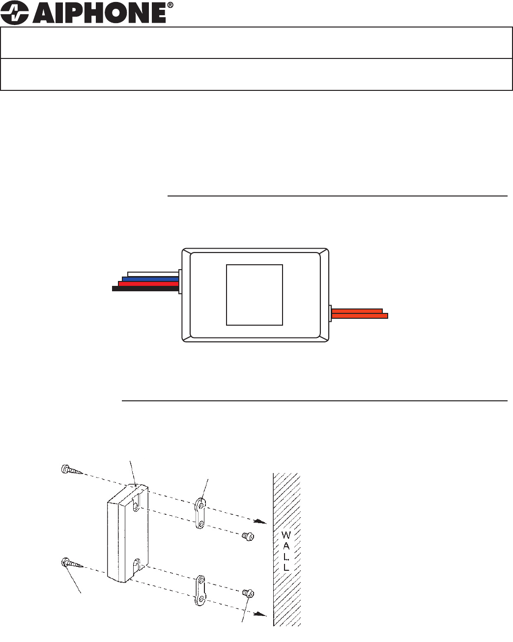
RY-ES
External Signaling Relay
- INSTALLATION & OPERATION INSTRUCTIONS -
Input of relay:
Red: Positive Power
Black: Negative Power
White: Activation wire
Blue: Activation wire
1 NAMES & FUNCTIONS
Output of relay:
2 Orange wires
N/O Dry contact closure
RY-ES
2 INSTALLATION
Wall mount the unit with the
supplied mounting hardware as
shown in the diagram to the left.
When making wire connections,
be sure not to short any wires
together. Use wire nuts or
another protective material to
isolate the connections.
Wood screw (2)
Screw (2)
RY-ES Mounting
bracket (2)
RY-ES Instructions
Pg. 2
3 WIRING DIAGRAMS
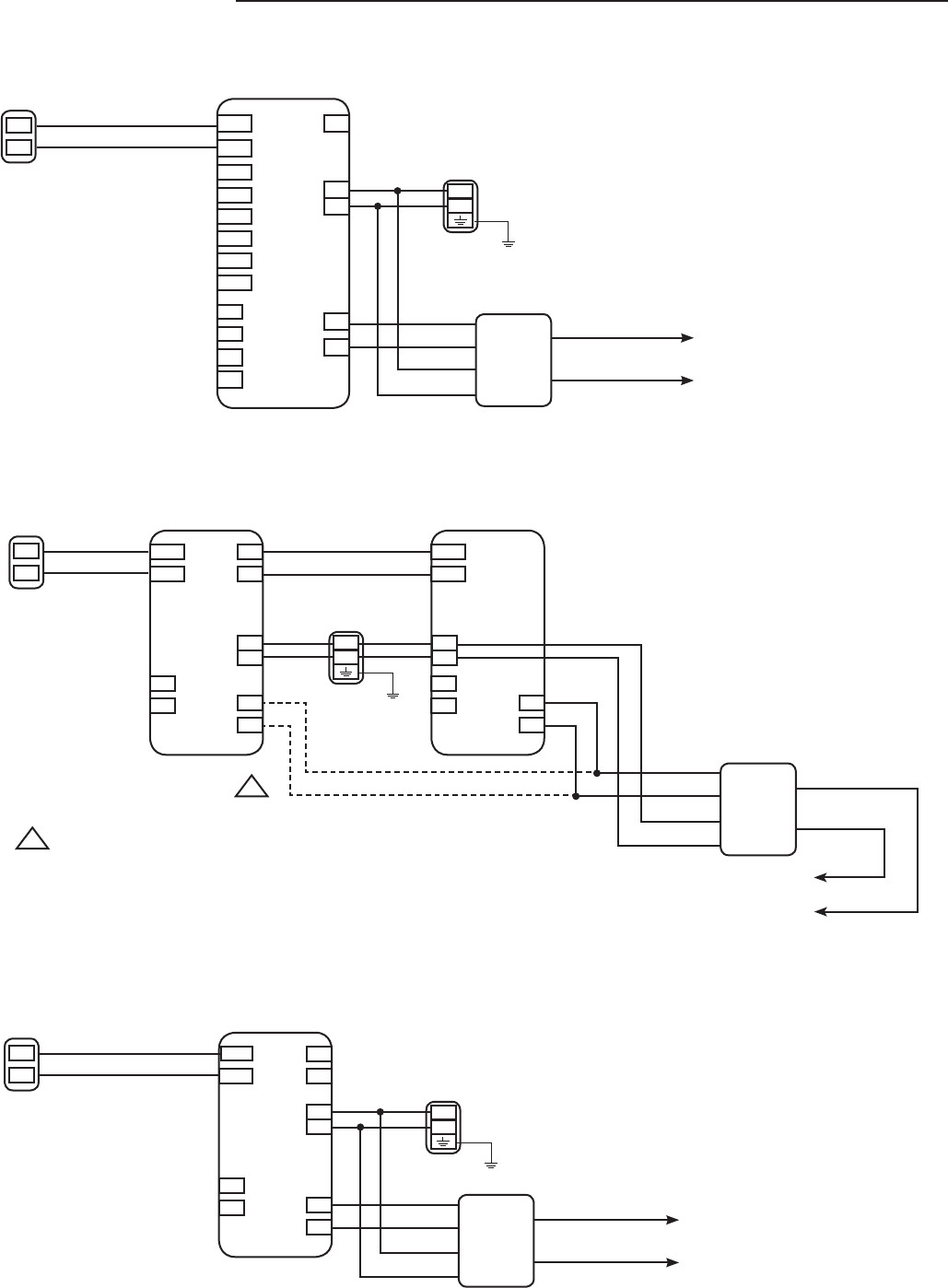
JK & JF Systems
A1
A2
+
-
JK-1MD/JK-1MED, JF-2MED
Door
A1
A2
B1
B2
+
-
S
S
L
L
DOOR
SUB OUTCALL EXT
PS-1820UL
Blue
White
Red
Black
JP System
A1
A2
+
-
JP-4MED
Door
1A1
1A2
+
-
S
S
L2
L2
M(OUT)
CALL EXT
PS-2420UL
Blue
White
Red
Black
Orange External Device
and Power
2A1
2A2
L1
L1
3A1
3A2
4A1
4A2
Orange External Device
and Power
JO System
A1
A2
Door
A1
A2
B1
B2
+
-
S
S
L
L
DOOR
MASTER
STATION
CALL EXT
A1
A2
+
-
S
S
L
L
DOOR
CALL EXT
PS-1820UL
+
-
JO-1FD
Expansion Station
JO-1MD
Master Station
Blue
White
Red
Black
Orange
External Device
and Power
Connect the RY-ES relay to either the JO-1MD master station or
the JO-1FD expansion station. Do not connect the same relay to
both stations.
!
!
RY-ES
RY-ES
RY-ES
RY-ES Instructions
Pg. 3
3 WIRING DIAGRAMS (cont)
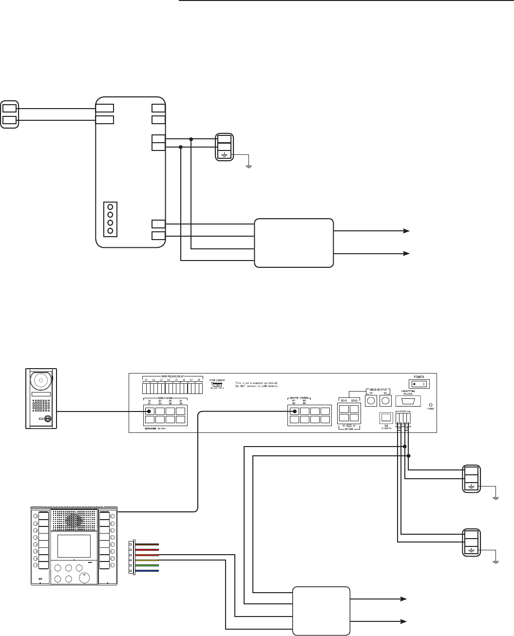
A1
A2
+
-
KB-3MRD
Door
1A1
1A2
B1
B2
+
-
S
S
Blue
White
Red
Black
External Device
and Power
Orange
KB System
AX System
PS-2420UL
External Device
and Power
Orange
-
+
PS-2420UL
-
+
PS-2420UL
Black
Red
White
Blue
Cat5e
Cat5e
AX-8M/AX-8MV
AX-DV
RY-ES
RY-ES
Aiphone Corporation
www.aiphone.com
tech@aiphone.com
(800) 692-0200
RY-ES Instructions
Pg. 4
0316JD
3 WIRING DIAGRAMS (cont)
A
M
E
1
~
10
M
E
S1
S1
+
-
+
-
NIM System
Blue
White
Red
Black External Device
and Power
Orange
NI-BA NIM-20B
IS-PU-UL
DB System
4 SPECIFICATIONS
Power Source: 12-30V DC, 12-16V AC. Power supplied by master.
Current consumption: DC: Standby 10mA. Max 60mA
AC: Standby 15mA. Max 70mA
Contact rating: 125V AC 1.0A
30V DC 1.0A
D
L
E
L
D
B3
B1
BL+
E
B4
B2
BL-
~ ~
15V
DA-1DS DB-1MD
PT-1211C
~ ~
RY-ES
Org
Yel Blue
White
Red
Black
External Device
and Power
Orange
IE System
IE Door IE-1GD / IE-2AD
RY-ES
Blue
White
Red
Black
External Device
and Power
Orange
1
2
D1
E1
(D2)
(E2)
T
R
C
E
+
-
PT-1210N
~
~
The RY-ES will work with the IE-1GD, IE-2AD, and IE-1AD.
Connections for the IE-1GD and IE-2AD are shown above.
When using the IE-1AD, connect the white/blue wires of the
RY-ES to the white leads of the unit.
The RY-ES is NOT compatible with the IE-8MD.
Connect the red and black wires of RY-ES to the M and E terminals of the NIM master
to power the relay. Do NOT connect to + and - of the NIM master.
RY-ES
