AirVast Technology WM168B 802.11b WLAN USB Module User Manual users manual
AirVast Technology Inc. 802.11b WLAN USB Module users manual
UserManual.wiki
>
AirVast Technology
>
WM168B User Manual
users manual
Navigation menu
Upload a User Manual
Namespaces
Wiki Guide
HTML
PDF
Info
Views
User Manual
Discussion / Help
Navigation
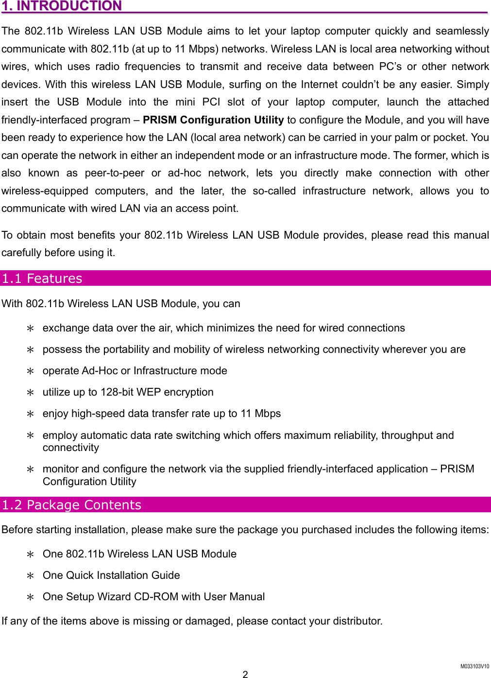
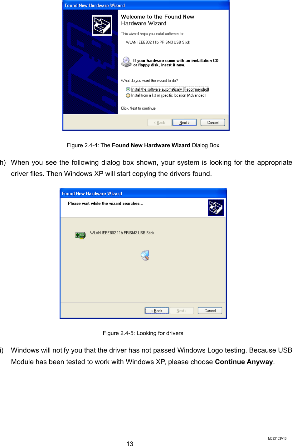
![M033103V10 12 Figure 2.4-2: The Welcome Dialog Box d) Choose Yes in the Software License Agreement dialog box to agree to it. If you click No, the setup will be interrupted. To go back to the previous dialog box, choose Back. e) In the Setup Complete dialog box, click Finish. Figure 2.4-3: The Setup Complete Dialog Box f) The Found New Hardware Wizard dialog box will appear and detect your 802.11b WLAN USB Module. g) Choose Install the software automatically [Recommended], and then click Next.](https://usermanual.wiki/AirVast-Technology/WM168B/User-Guide-318708-Page-18.png)
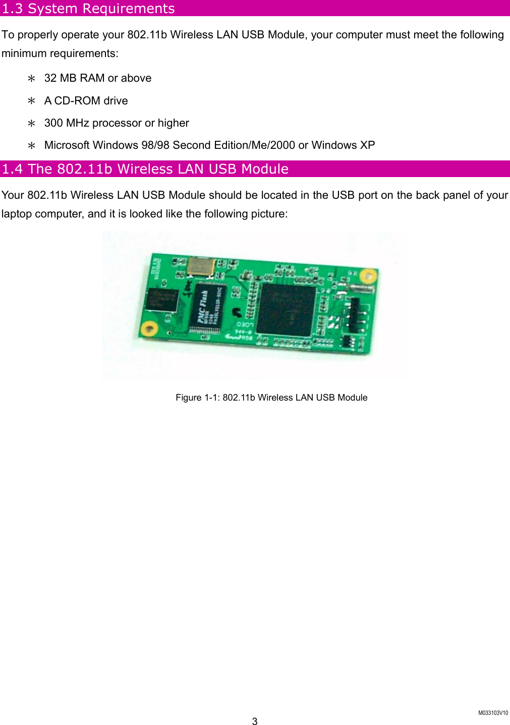
![M033103V10 36 12. Click Finish when you see the following window. The driver and software installations are entirely complete at the time. Figure 5-10: The Complete Screen For Windows 98: Close the Close Program Dialog Box During the Installation If you are using Windows 98, during the installation process, you might be notified with the Close Program dialog box after indicating the Windows to install the required files on the Windows 98 CD-ROM. Figure 5-11: The Close Program Dialog Box This is however normal. The dialog box displays a list of all presently active programs. Choose New Hardware found [Not responding], and then click the End Task button. Then you can monitor and configure the network via PRISM Client Utility according to your needs.](https://usermanual.wiki/AirVast-Technology/WM168B/User-Guide-318708-Page-42.png)