AirVast Technology WM168B 802.11b WLAN USB Module User Manual users manual
AirVast Technology Inc. 802.11b WLAN USB Module users manual
users manual

802.11b Wireless LAN USB Module
User Manual
Version 1.0
M033103V10
1
No part of this documentation may be reproduced in any form or by any means or used to make any
derivative work (such as translation, transformation, or adaptation) without written permission from the
copyright owner.
All the other trademarks and registered trademarks are the property of their respective owners.
Statement of Conditions
We may make improvements or changes in the product described in this documentation at any time. The information
regarding to the product in this manual are subject to change without notice.
We assumes no responsibility for errors contained herein or for direct, indirect, special, incidental, or consequential
damages with the furnishing, performance, or use of this manual or equipment supplied with it, even if the suppliers
have been advised of the possibility of such damages.
Electronic Emission Notices
This device complies with Part 15 of the FCC Rules. Operation is subject to the following two conditions:
(1)This device may not cause harmful interference.
(2)This device must accept any interference received, including interference that may cause undesired operation.
FCC INFORMATION
The Federal Communication Commission Radio Frequency Interference Statement includes the following paragraph:
The equipment has been tested and found to comply with the limits for a Class B Digital Device, pursuant to part 15 of
the FCC Rules. These limits are designed to provide reasonable protection against harmful interference in a residential
installation. This equipment generates, uses and can radiate radio frequency energy and, if not installed and used in
accordance with the instruction, may cause harmful interference to radio communication. However, there is no grantee
that interference will not occur in a particular installation. If this equipment dose cause harmful interference to radio or
television reception, which can be determined by turning the equipment off and on, the user is encouraged to try to
correct the interference by one or more of the following measures:
--Reorient or relocate the receiving antenna.
--Increase the separation between the equipment and receiver.
--Connect the equipment into an outlet on a circuit different from that to which the receiver is connected.
--Consult the dealer or an experienced radio/TV technician for help.
The equipment is for home or office use.
R&TTE Compliance Statement
This equipment complies with all the requirements of the Directive 1999/5/EC of the European parliament and the
council of 9 March 1999 on radio equipment and telecommunication terminal Equipment and the mutual
recognition of their conformity(R&TTE).
The R&TTE Directive repeals and replaces in the directive 98/13/EEC. As of April 8, 2000.
IMPORTANT NOTE
FCC RF Radiation Exposure Statement: This equipment complies with FCC RF radiation exposure limits set forth
for an uncontrolled environment. This equipment should be installed and operated with a minimum distance of
20cm between the antenna and your body and must not be co-located or operating in conjunction with any other
antenna or transmitter.
Caution: Changes or modifications not expressly approved by the party responsible for compliance could void
the user's authority to operate the equipment.
M033103V10
2
STATEMENT FOR MODUAL APPROVAL
This product is sold to OEM integrators only. The manual for the OEM integrators must include some instructions
that must be followed by the end users in the user manual. For example:
- The OEM integrators must be instructed to ensure that the end user has no manual instructions to remove or
install the device.
- The OEM integrators must be instructed about the end product labeling ("Contains TX FCC ID: QDWWM168B")
etc.
Please add the following statements to the manuals for the OEM integrators:
This device is intended only for OEM integrators under the following conditions:
1) The antenna must be installed such that 20 cm is maintained between the antenna and users, and
2) The transmitter module may not be co-located with any other transmitter or antenna.
As long as 2 conditions above are met, further transmitter test will not be required. However, the OEM integrator
is still responsible for testing their end product for any additional compliance requirements required with this
module installed (for example, digital device emissions, PC peripheral requirements, etc.).
IMPORTANT NOTE: In the event that these conditions cannot be met (for example certain laptop configurations
or co-location with another transmitter), then the FCC authorization is no longer considered valid and the FCC ID
cannot be used on the final product. In these circumstances, the OEM integrator will be responsible for
re-evaluating the end product (including the transmitter) and obtaining a separate FCC authorization.
End Product Labeling
This transmitter module is authorized only for use in device where the antenna may be installed such that 20 cm
may be maintained between the antenna and users (for example, access points, routers, wireless ADSL modems,
and similar equipment). The final end product must be labeled in a visible area with the following: "Contains TX
FCC ID: QDWWM168B".
Manual Information for End Users
The end user must not have manual instructions to remove or install the device.
The user manual for end users must include the following information in a prominent location.
“IMPORTANT NOTE: To comply with FCC RF exposure compliance requirements, this grant is applicable to
only Mobile Configurations. The antennas used for this transmitter must be installed to provide a separation distance
of at least 20 cm from all persons and must not be co-located or operating in conjunction with any other antenna or transmitter.

Table of Contents
1. INTRODUCTION .............................................................................................................................................2
1.1 FEATURES ......................................................................................................................................................2
1.2 PACKAGE CONTENTS.....................................................................................................................................2
1.3 SYSTEM REQUIREMENTS...............................................................................................................................3
1.4 THE 802.11B WIRELESS LAN USB MODULE ...............................................................................................3
2. INSTALLATION OF THE 802.11b WIRELESS LAN USB MODULE ......................................................4
2.1 INSTALLATION PROCEDURES FOR WINDOWS 98 USERS................................................................................4
3.2 INSTALLATION PROCEDURES FOR WINDOWS 98SE / ME USERS ..................................................................6
2.3 INSTALLATION PROCEDURES FOR WINDOWS 2000 USERS............................................................................8
2.4 INSTALLATION PROCEDURES FOR WINDOWS XP USERS.............................................................................11
2.5 VERIFYING A SUCCESSFUL INSTALLATION ..................................................................................................16
3. CONFIGURATION FOR WINDOWS XP ...................................................................................................18
TO CONNECT AN AVAILABLE NETWORK VIA WIRELESS ZERO CONFIGURATION ..............................................18
TO CONFIGURE THE WIRELESS NETWORKS PROPERTIES..................................................................................19
TO ACCESS TO CERTAIN WIRELESS NETWORK TYPE........................................................................................21
4. PRISM CONFIGURATION UTILITY BASICS .........................................................................................23
4.1 TRAY ICON...................................................................................................................................................23
4.2 RIGHT-CLICK MENU OF THE TRAY ICON .....................................................................................................23
Wireless Radio On ........................................................................................................................................24
Wireless Radio Off ........................................................................................................................................24
Remove Status Icon.......................................................................................................................................24
Wireless Network Status................................................................................................................................24
Advanced Configuration...............................................................................................................................25
WEP Encryption ...........................................................................................................................................25
Version Information ......................................................................................................................................25
4.3 THE UTILITY FUNCTION ..............................................................................................................................25
The Status Tab...............................................................................................................................................25
State..........................................................................................................................................................26
Current Tx Rate ........................................................................................................................................26
Current Channel .......................................................................................................................................26
M033103V10
1
Throughout (bytes/sec).............................................................................................................................26
Link Quality .............................................................................................................................................27
Signal Strength .........................................................................................................................................27
The Configuration Tab..................................................................................................................................27
Profile Name ............................................................................................................................................27
Network Name .........................................................................................................................................28
Network Type ...........................................................................................................................................28
Peer-to-Peer Channel................................................................................................................................28
Transmit Rate ...........................................................................................................................................28
The Encryption Tab.......................................................................................................................................28
Encryption (WEP security).......................................................................................................................29
Create Key Manual...................................................................................................................................29
Use WEP Key...........................................................................................................................................29
Create Keys with Passphrase....................................................................................................................30
The About Tab...............................................................................................................................................30
Network Driver ........................................................................................................................................30
Configuration Utility ................................................................................................................................30
NIC Firmware ..........................................................................................................................................30
APPENDIX A: TROUBLESHOOTING ...........................................................................................................31
UNINSTALL RRISM CONFIGURATION UTILITY AND THE MODULE’S DRIVER ..................................................31
THE 802.11B WLAN USB MODULE DOES NOT WORK PROPERLY ..................................................................31
UPGRADE RRISM CONFIGURATION UTILITY AND THE MODULE’S DRIVER.....................................................31
FOR WINDOWS 98: CLOSE THE CLOSE PROGRAM DIALOG BOX DURING THE INSTALLATION .........................36
APPENDIX B: SPECIFICATIONS...................................................................................................................37
APPENDIX C: GLOSSARY ..............................................................................................................................38

List of Figures
FIGURE 1-1: 802.11b WIRELESS LAN USB MODULE .............................................................................................3
FIGURE 2.1-1: THE PRISM DRIVER FOR WINDOWS –WELCOME DIALOG BOX .................................................4
FIGURE 2.1-2: THE WELCOME DIALOG BOX .........................................................................................................4
FIGURE 2.1-3: THE SOFTWARE LICENSE AGREEMENT DIALOG BOX ...................................................................5
FIGURE 2.1-4: THE SETUP COMPLETE DIALOG BOX .............................................................................................5
FIGURE 2.1-5: THE INSERT DISK MESSAGE BOX ...................................................................................................5
FIGURE 2.2-1: THE PRISM DRIVER FOR WINDOWS –WELCOME DIALOG BOX .................................................6
FIGURE 2.2-2: THE WELCOME DIALOG BOX .........................................................................................................7
FIGURE 2.2-3: THE SOFTWARE LICENSE AGREEMENT DIALOG BOX ...................................................................7
FIGURE 2.2-4: THE SETUP COMPLETE DIALOG BOX .............................................................................................8
FIGURE 2.2-5: THE NEW HARDWARE FOUND MESSAGE BOX ...............................................................................8
FIGURE 2.3-1: THE PRISM DRIVER FOR WINDOWS –WELCOME DIALOG BOX .................................................9
FIGURE 2.3-2: THE WELCOME DIALOG BOX .........................................................................................................9
FIGURE 2.3-3: THE SOFTWARE LICENSE AGREEMENT DIALOG BOX .................................................................10
FIGURE 2.3-4: THE SETUP COMPLETE DIALOG BOX ...........................................................................................10
FIGURE 2.3-5: THE DIGITAL SIGNATURE NOT FOUND DIALOG BOX ..................................................................11
FIGURE 2.4-1: THE PRISM DRIVER FOR WINDOWS –WELCOME DIALOG BOX ...............................................11
FIGURE 2.4-2: THE WELCOME DIALOG BOX .......................................................................................................12
FIGURE 2.4-3: THE SETUP COMPLETE DIALOG BOX ...........................................................................................12
FIGURE 2.4-4: THE FOUND NEW HARDWARE WIZARD DIALOG BOX.................................................................13
FIGURE 2.4-5: LOOKING FOR DRIVERS ..................................................................................................................13
FIGURE 2.4-6: THE HARDWARE INSTALLATION DIALOG BOX ............................................................................14
FIGURE 2.4-7: THE COMPLETE SCREEN ...............................................................................................................14
FIGURE 2.4-8: THE PRISM CONFIGURATION UTILITY TRAY ICON....................................................................15
FIGURE 2.4-9: THE PRISM WIRELESS SETTINGS DIALOG BOX.........................................................................15
FIGURE 2.4-10: THE WIRELESS NETWORK CONNECTION STAT US DIALOG BOX ..............................................15
FIGURE 2.4-11: THE WIRELESS NETWORK CONNECTION PROPERTIES DIALOG BOX......................................16
FIGURE 2.5-1: THE DEVICE MANAGER DIALOG BOX ..........................................................................................17
FIGURE 3-1: THE WIRELESS NETWORK CONNECTION ICON..............................................................................18
FIGURE 3-2: THE CONNECT TO WIRELESS NETWORK DIALOG BOX .................................................................18
FIGURE 3-3: THE CONNECT TO WIRELESS NETWORK DIALOG BOX .................................................................19
FIGURE 3-4: THE WIRELESS NETWORK CONNECTION PROPERTIES DIALOG BOX...........................................19
FIGURE 3-5: THE WIRELESS NETWORK PROPERTIES DIALOG BOX ..................................................................20
FIGURE 3-6: ENTER WEP ......................................................................................................................................21
FIGURE 3-7: SETTING UP WIRELESS NETWORK CONFIGURATION ..........................................................................21
M033103V10
1
FIGURE 3-8 THE ADVANCED DIALOG BOX: ..........................................................................................................22
FIGURE 4.2-1: RIGHT-CLICK MENU OF THE TRAY ICON.........................................................................................24
FIGURE 4.2-2: THE REMOVE WIRELESS STAT US ICON DIALOG BOX .................................................................24
FIGURE 4.3-1: THE PRISM WIRELESS SETTINGS DIALOG BOX.........................................................................25
FIGURE 4.3-2: THE STATUS TAB ............................................................................................................................26
FIGURE 4.3-3: THE CONFIGURATION TAB............................................................................................................27
FIGURE 4.3-4: THE ENCRYPTION TAB ..................................................................................................................29
FIGURE 4.2-14: THE ABOUT TAB ..........................................................................................................................30
FIGURE 5-1: THE DEVICE MANAGER DIALOG BOX .............................................................................................32
FIGURE 5-2: THE DRIVER TAB ..............................................................................................................................32
FIGURE 5-3: THE UPGRADE DEVICE DRIVER WIZARD DIALOG BOX.................................................................33
FIGURE 5-4: THE INSTALL HARDWARE DEVICE DRIVERS SCREEN ....................................................................33
FIGURE 5-5: THE HARDWARE TYPE SCREEN .......................................................................................................34
FIGURE 5-6: THE SELECT NETWORK ADAPTER SCREEN ....................................................................................34
FIGURE 5-7: THE UPDATE DRIVER WANING MESSAGE BOX ...............................................................................35
FIGURE 5-8: THE START DEVICE DRIVER INSTALLATION DIALOG BOX ............................................................35
FIGURE 5-9: THE DIGITAL SIGNATURE NOT FOUND DIALOG BOX .....................................................................35
FIGURE 5-10: THE COMPLETE SCREEN ................................................................................................................36
FIGURE 5-11: THE CLOSE PROGRAM DIALOG BOX .............................................................................................36

M033103V10
2
1
1.
.
I
IN
NT
TR
RO
OD
DU
UC
CT
TI
IO
ON
N
The 802.11b Wireless LAN USB Module aims to let your laptop computer quickly and seamlessly
communicate with 802.11b (at up to 11 Mbps) networks. Wireless LAN is local area networking without
wires, which uses radio frequencies to transmit and receive data between PC’s or other network
devices. With this wireless LAN USB Module, surfing on the Internet couldn’t be any easier. Simply
insert the USB Module into the mini PCI slot of your laptop computer, launch the attached
friendly-interfaced program – PRISM Configuration Utility to configure the Module, and you will have
been ready to experience how the LAN (local area network) can be carried in your palm or pocket. You
can operate the network in either an independent mode or an infrastructure mode. The former, which is
also known as peer-to-peer or ad-hoc network, lets you directly make connection with other
wireless-equipped computers, and the later, the so-called infrastructure network, allows you to
communicate with wired LAN via an access point.
To obtain most benefits your 802.11b Wireless LAN USB Module provides, please read this manual
carefully before using it.
1.1 Features
With 802.11b Wireless LAN USB Module, you can
* exchange data over the air, which minimizes the need for wired connections
* possess the portability and mobility of wireless networking connectivity wherever you are
* operate Ad-Hoc or Infrastructure mode
* utilize up to 128-bit WEP encryption
* enjoy high-speed data transfer rate up to 11 Mbps
* employ automatic data rate switching which offers maximum reliability, throughput and
connectivity
* monitor and configure the network via the supplied friendly-interfaced application – PRISM
Configuration Utility
1.2 Package Contents
Before starting installation, please make sure the package you purchased includes the following items:
* One 802.11b Wireless LAN USB Module
* One Quick Installation Guide
* One Setup Wizard CD-ROM with User Manual
If any of the items above is missing or damaged, please contact your distributor.
M033103V10
3
1.3 System Requirements
To properly operate your 802.11b Wireless LAN USB Module, your computer must meet the following
minimum requirements:
* 32 MB RAM or above
* A CD-ROM drive
* 300 MHz processor or higher
* Microsoft Windows 98/98 Second Edition/Me/2000 or Windows XP
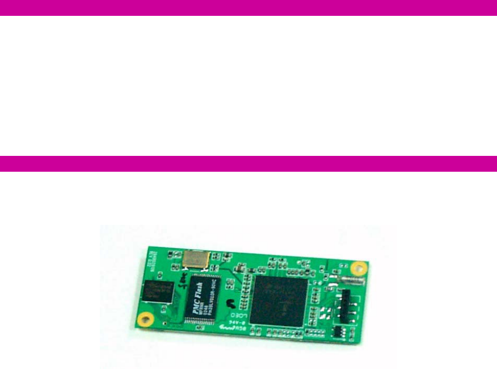
1.4 The 802.11b Wireless LAN USB Module
Your 802.11b Wireless LAN USB Module should be located in the USB port on the back panel of your
laptop computer, and it is looked like the following picture:
Figure 1-1: 802.11b Wireless LAN USB Module
M033103V10
4
2
2.
.
I
IN
NS
ST
TA
AL
LL
LA
AT
TI
IO
ON
N
O
OF
F
T
TH
HE
E
8
80
02
2.
.1
11
1b
b
W
WI
IR
RE
EL
LE
ES
SS
S
L
LA
AN
N
U
US
SB
B
M
MO
OD
DU
UL
LE
E
Please refer to the proper section corresponding with operating system you are using to fully install
your 802.11b Wireless LAN USB Module and the attached software - PRISM Configuration Utility.
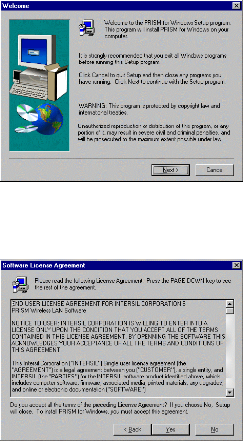
2.1 Installation Procedures for Windows 98 Users
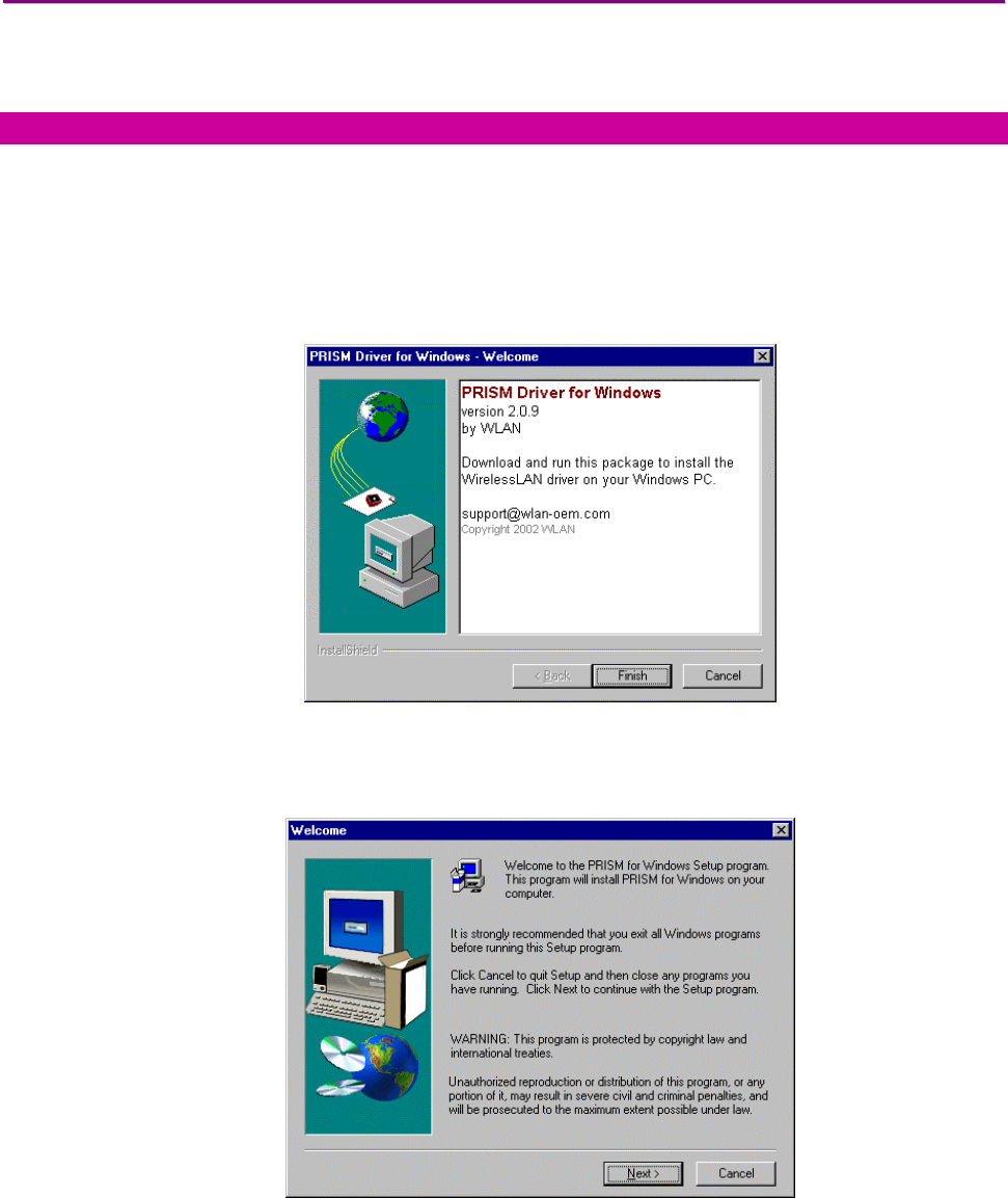
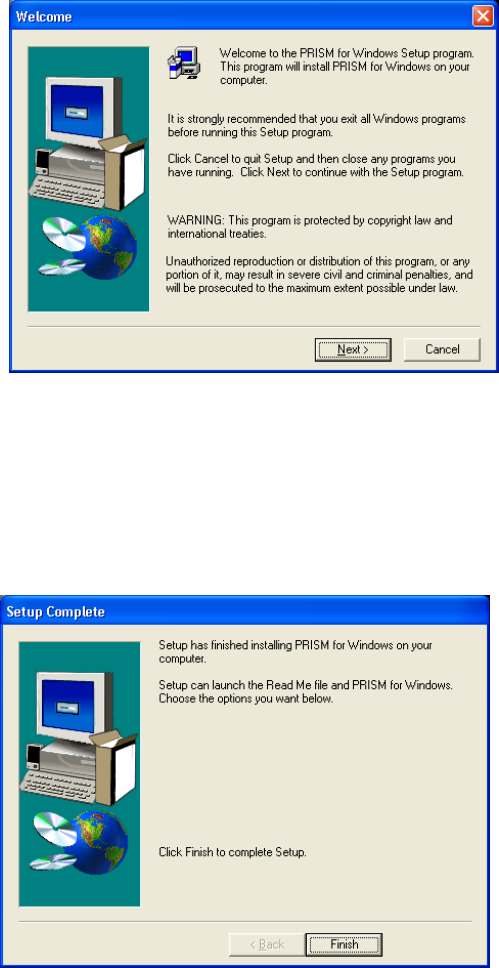
a) Insert the supplied Setup CD into your CD-ROM drive, the Setup Wizard will run
automatically. If it does not, please manually execute setup.exe.
b) The
PRISM Driver for Windows –Welcome dialog box will be prompted. Click Finish to
continue.
Figure 2.1-1: The PRISM Driver for Windows –Welcome Dialog Box
c) Click
Next in the Welcome dialog box to proceed.
Figure 2.1-2: The Welcome Dialog Box
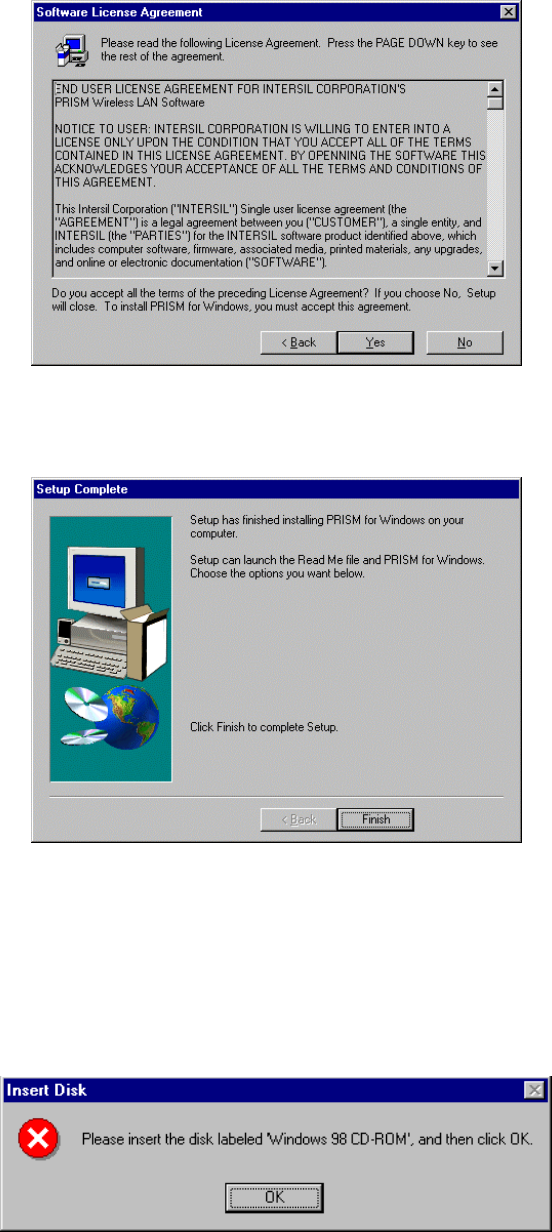
d) In the
Software License Agreement dialog box, choose Yes to accept the agreement.
M033103V10
5
Click No will stop the installation. To go back to the previous dialog box, choose Back.
Figure 2.1-3: The Software License Agreement Dialog Box
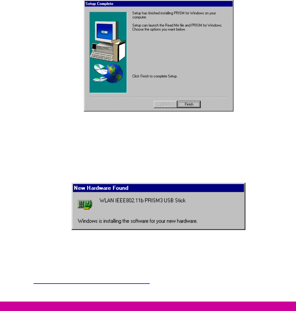
e) Click
Finish in the prompted Setup Complete dialog box.
Figure 2.1-4: The Setup Complete Dialog Box
f) Restart your computer then.
g) After rebooting, Windows will automatically detect the 802.11b Wireless LAN USB Module
and display the New Hardware Found message box. At the same time, you will be asked
to insert the Windows 98 CD-ROM, please do so and click OK to proceed.
Figure 2.1-5: The Insert Disk Message Box
M033103V10
6
h) In the Copying Files dialog box, click Browse to indicate Windows to install the
appropriate file from the folder named WIN98 on the CD-ROM, and then click OK. In a few
seconds, the installation is entirely complete.
To set configurations for the network connection, double-click the PRISM Configuration
Utility icon, which is already displayed in the system tray. For more details about the
application, please refer to PRISM Configuration Utility Basics in this manual.
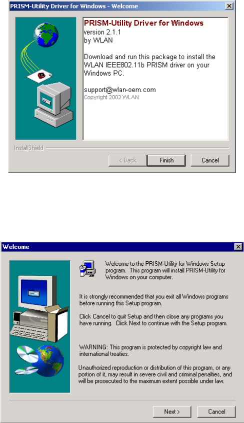
3.2 Installation Procedures for Windows 98SE / Me Users
The installation under Windows Me is very similar to that under Windows 98SE. Please go through the
instructions below if you are using Windows Me or Window 98 SE.
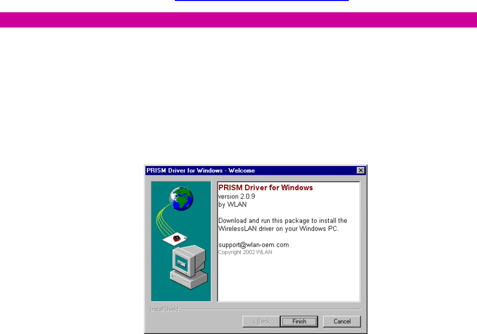
a) Insert the supplied Setup CD into your CD-ROM drive, the Setup Wizard will run
automatically. If it does not, please manually execute setup.exe.
b) The
PRISM Driver for Windows –Welcome dialog box will be prompted. Click Finish to
continue.
Figure 2.2-1: The PRISM Driver for Windows –Welcome Dialog Box
c) In the
Welcome dialog box, click Next to proceed.
M033103V10
7
Figure 2.2-2: The Welcome Dialog Box
d) In the
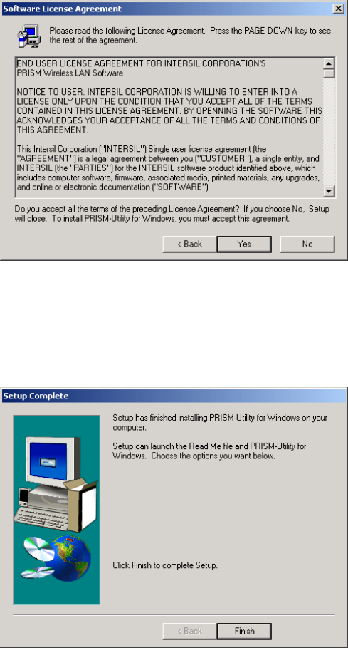
Software License Agreement dialog box, choose Yes to accept the agreement.
Click No will stop the installation.
Figure 2.2-3: The Software License Agreement Dialog Box
e) When the
Setup Complete dialog box is prompted, click Finish.
M033103V10
8
Figure 2.2-4: The Setup Complete Dialog Box
f) Restart your computer then.
g) After rebooting, Windows will automatically detect the 802.11b Wireless LAN USB Module
and display the New Hardware Found message box as below. Meanwhile, you will find
the PRISM Configuration Utility icon appeared in the system tray.
Figure 2.2-5: The New Hardware Found Message Box
Within a few seconds, windows will automatically finish installing the hardware drivers.
To configure the PRISM Configuration Utility, simply double-click the tray icon. The
PRISM Configuration Utility Basics chapter below offers you information on the
application in detail.
2.3 Installation Procedures for Windows 2000 Users
a) Insert the supplied Setup CD into your CD-ROM drive, the Setup Wizard will run
automatically. If it does not, please manually execute setup.exe.
b) The PRISM Driver for Windows –Welcome dialog box will pop up. Click Finish to
continue.
M033103V10
9
Figure 2.3-1: The PRISM Driver for Windows –Welcome Dialog Box
c) In the opened Welcome dialog box, click Next. Choose Cancel will stop off the installation.
Figure 2.3-2: The Welcome Dialog Box
d) Choose
Yes in the Software License Agreement dialog box to accept the agreement. If
you click No, the setup will be interrupted. To go back to the previous dialog box, choose
Back.
M033103V10
10
Figure 2.3-3: The Software License Agreement Dialog Box
e) Click
Finish when the Setup Complete dialog box appears to complete installing the
attached utility.
Figure 2.3-4: The Setup Complete Dialog Box
f) Windows 2000 will automatically detect your 802.11b WLAN USB Module and start up the
installation with the appearance of the Found New Hardware message box.
g) Then you will be notified that the driver has not passed Windows Logo testing. Because
USB Module has been tested to work with Windows 2000, click the Yes button in the
Digital Signature Not Found dialog box.
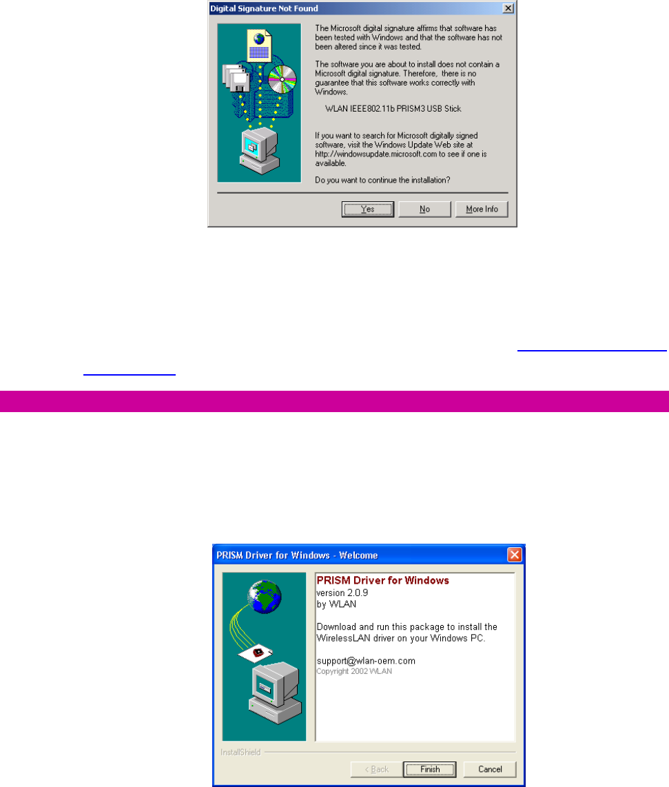
M033103V10
11
Figure 2.3-5: The Digital Signature Not Found Dialog Box
The installation is entirely finished afterwards. Double-click the PRSIM Configuration
Utility tray icon on the right bottom of the screen to arrange more settings for the network
connection. To learn more about the application, please refer to PRISM Configuration
Utility Basics in this manual
2.4 Installation Procedures for Windows XP Users
a) Insert the supplied Setup CD into your CD-ROM drive, the Setup Wizard will run
automatically. If it does not, please manually execute setup.exe.
b) The PRISM Driver for Windows –Welcome dialog box will be shown. Click Finish to
continue.
Figure 2.4-1: The PRISM Driver for Windows –Welcome Dialog Box
c) Click
Next in the Welcome dialog box. Choose Cancel will stop off the installation.
M033103V10
12
Figure 2.4-2: The Welcome Dialog Box
d) Choose
Yes in the Software License Agreement dialog box to agree to it. If you click No,
the setup will be interrupted. To go back to the previous dialog box, choose Back.
e) In the
Setup Complete dialog box, click Finish.
Figure 2.4-3: The Setup Complete Dialog Box
f) The
Found New Hardware Wizard dialog box will appear and detect your 802.11b WLAN
USB Module.
g) Choose Install the software automatically [Recommended], and then click Next.

M033103V10
13
Figure 2.4-4: The Found New Hardware Wizard Dialog Box
h) When you see the following dialog box shown, your system is looking for the appropriate
driver files. Then Windows XP will start copying the drivers found.
Figure 2.4-5: Looking for drivers
i) Windows will notify you that the driver has not passed Windows Logo testing. Because USB
Module has been tested to work with Windows XP, please choose Continue Anyway.
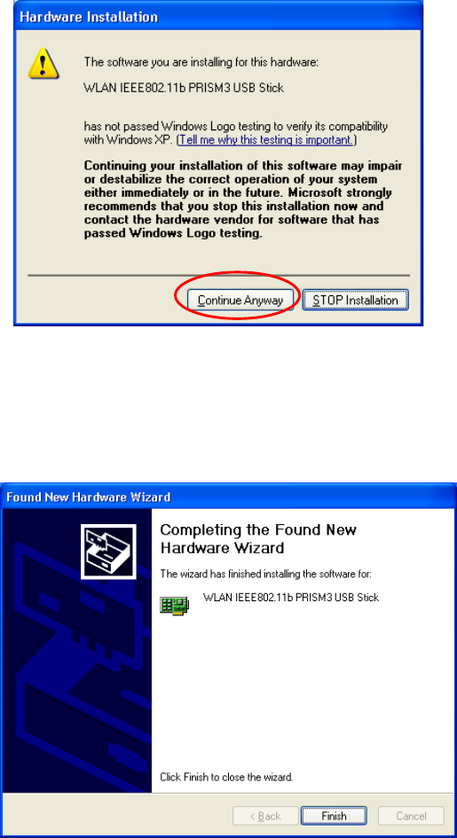
M033103V10
14
Figure 2.4-6: The Hardware Installation Dialog Box
j) Click the
Finish button after seeing the Completing the Found New Hardware Wizard
screen.
Figure 2.4-7: The Complete Screen
k) You will find the PRISM Configuration Utility icon appeared in the system tray.
Double-click the icon to launch the application and open the PRISM Wireless Settings
dialog box, in which two tabs are contained. However, normally, the dialog box should be
consisted of four tabs. This is because Windows XP has its built-in configuration tools –
Windows XP Zero Configuration to assist you in networking activities. It is recommended
to utilize the attached PRISM Configuration Utility to enjoy more benefits it will bring. Thus,
to employ your PRISM Configuration Utility under Windows XP, please proceed to the
next step to change the default settings of Windows Zero Configuration to PRISM
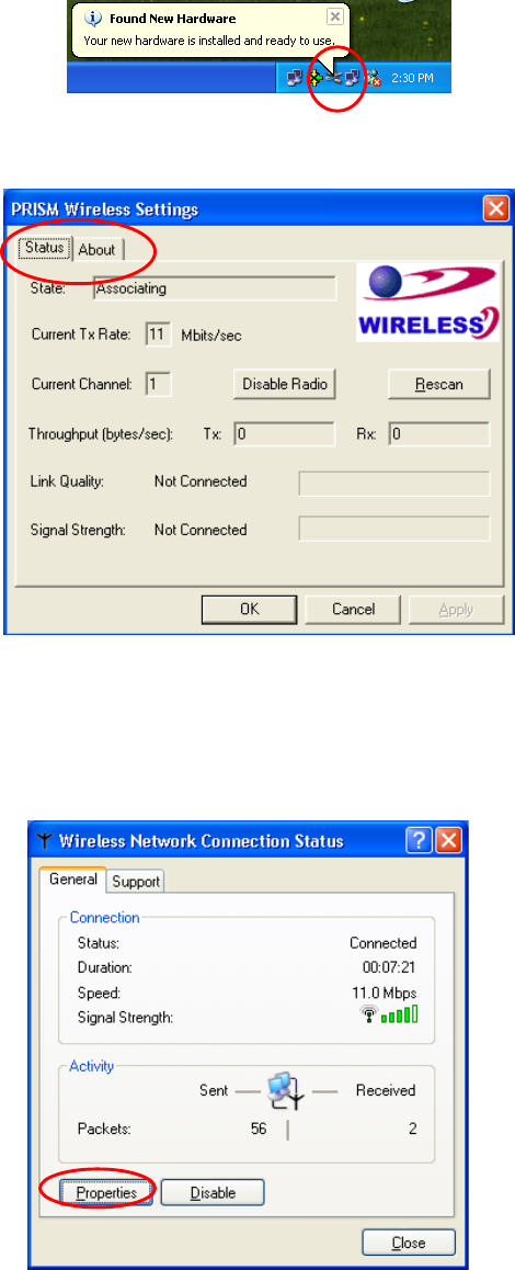
M033103V10
15
Configuration Utility.
Figure 2.4-8: The PRISM Configuration Utility Tray Icon
Figure 2.4-9: The PRISM Wireless Settings Dialog Box
l) Right-click the Network Connections icon at the task bar to open the Wireless Network
Connection Status dialog box, and then select Properties.
Figure 2.4-10: The Wireless Network Connection Status Dialog Box
m) Choose the Wireless Networks tab in the Wireless Network Connection Properties
M033103V10
16
dialog box, and remove the tick in the Use Windows to configure my wireless network
settings checkbox.
Figure 2.4-11: The Wireless Network Connection Properties Dialog Box
n) Click
OK. Now, you have successfully removed the Windows Zero Configuration.
To monitor and configure the network via PRISM Configuration Utility, double-click its
tray icon, and you should find four tabs contained in the popped up PRISM Wireless
Settings dialog box at this time. For more details about the utility, please refer to PRISM
Configuration Utility Basics below.
Note: If you wish to use Windows XP’s built-in configuration tools – Windows XP Zero Configuration,
please refer to the next chapter: Configuration for Windows XP to configure the WLAN USB Module.
2.5 Verifying a Successful Installation
To confirm that your 802.11b Wireless LAN USB Module is properly installed, please go along with the
procedures below.
1. Right-click the
My Computer desktop icon, and choose Properties from the opened menu.
2. In the
System Properties dialog box, choose Device Manager if you are under Windows 98
or Me. If you are operating Windows 2000 or XP, click the Hardware tab, and then choose
the Device Manager button.
3. In the opened window, expanding Network adapters to find the USB Module - WLAN
IEEE802.11b PRISM USB Adapter. Right-click over the item and choose Properties.
M033103V10
17
4. From the opened dialog box, on the General tab, find the descriptions under the Device
Status pane to learn if the module is working properly. However, if there’s an error message
shown, please choose Uninstall from the opened menu while right-clicking over the USB
Adapter item, which is attached a red or yellow icon beside, in the Device Manager dialog
box. Then restart your system and go through the installation procedures again.
The following picture indicates a successful installation of the 802.11b Wireless LAN USB Module.
Figure 2.5-1: The Device Manager Dialog Box
M033103V10
18
3
3.
.
C
CO
ON
NF
FI
IG
GU
UR
RA
AT
TI
IO
ON
N
F
FO
OR
R
W
WI
IN
ND
DO
OW
WS
S
X
XP
P
As you have already known, Windows XP has its built-in configuration tools – Windows XP Zero
Configuration, to assist you in some basic configurations of wireless network connection. The service
starts right after the completion of the installation of 802.11b WLAN USB Module, and you will find the
icon automatically appears in your system tray like the following picture shows.
Figure 3-1: The Wireless Network Connection Icon
Please refer to the desired topics below to look for more details about utilizing your 802.11b WLAN
USB Module via Wireless Zero Configuration.
To Connect an Available Network via Wireless Zero Configuration
1. Double-click the
Wireless Network Connection icon.
2. In the opened Connect to Wireless Network dialog box, the currently available networks
are listed in the Available networks field. From the list, click an item which you intend to
make an association.
3. If the chosen entry requires a WEP encryption key and also automatically provides it, leave
the Network Key field blank, and then choose the Connect button to build the connection.
Otherwise, you will need to manually enter the identical key in the Network Key field before
clicking Connect.
Figure 3-2: The Connect to Wireless Network Dialog Box
4. If the connection is established, there will be a pop-up message shown beside the Wireless
Network Connection icon on the system tray. You could obtain the information on the status
of connection from the message.
M033103V10
19
To Configure the Wireless Networks Properties
If you cannot establish a connection with the chosen entry or you wish to configure further wireless
network connection settings, choose the Advanced button in the Connect to Wireless Network
dialogue box.
Figure 3-3: The Connect to Wireless Network Dialog Box
After clicking Advanced, you will enter into the Wireless Networks tab of the Wireless Network
Connection Properties dialog box, in which there are three other tabs, including General,
Authentication, and Advanced. The Wireless Networks tab includes almost the main settings for
the networking connection. Thus, please check the descriptions below to learn more about the tab.
Figure 3-4: The Wireless Network Connection Properties Dialog Box
Note: For more detailed information about each tab, please refer to the Windows XP Online-Help.
M033103V10
20
The Wireless Networks tab is mainly consisted of two sections: Available networks and Preferred
networks.
Under the Available networks area, all the available access points or Wireless LAN PC Card
equipped computers are displayed. You may wish to click Refresh to update the list. If you
choose any listed item in the field and then click Configure, the Wireless Network Properties
dialog box will appear, as Figure 3-5 shows. Check the description below the figure to obtain more
information about the dialog box.
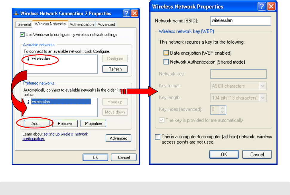
In the Preferred networks area, you could add any displayed networks to the list by clicking over
the intended item from Available networks, and then select the Add button. After clicking Add,
the Wireless Network Properties dialog box will appear as Figure 3-5 displays. Note that to
delete any item under the Preferred networks area, simply click on it and then select the
Remove button. Additionally, you may adjust the items in the list by clicking the desired item and
then choosing the Move up or Move down button. It is, however, important to realize that
Windows XP will always choose the first one in the list to establish the networking connection.
Figure 3-5: The Wireless Network Properties Dialog Box
Note: Once you click over an item from the Preferred networks list and then choose Properties, the Wireless
Network Properties will also be provoked.
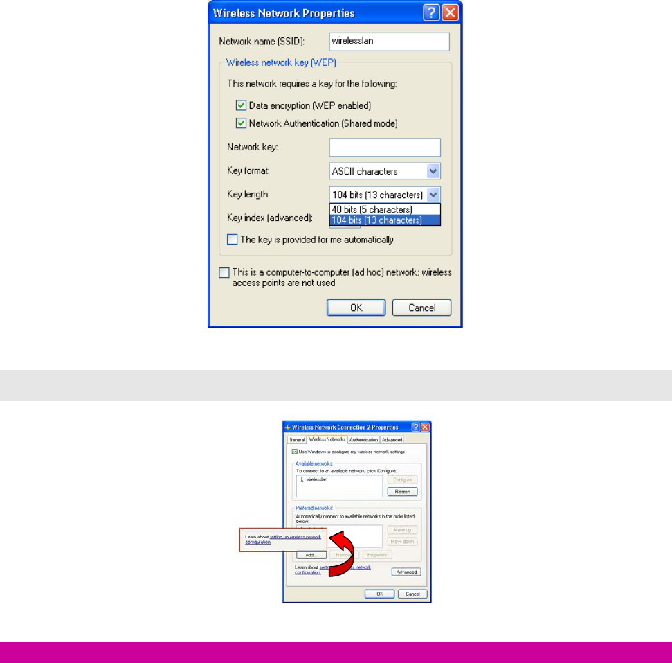
In the opened Wireless Network Properties dialog box, edit texts in the Network Name (SSID)
field to identify the chosen network entry in the wireless LAN.
If there’s a need, go to the Wireless network key (WEP) area below to set the keys as the
associated access point or Wireless LAN PC Card equipped computer requests. To set WEP,
select Data encryption (WEP enabled) and Network Authentication. Then enter the encryption
M033103V10
21
keys for the network you intend to connect in the Network Key field. Meanwhile, the Key format
and Key length options change the settings according to Network Key string you typed. Click
OK when you are finished, and you will be back to the Wireless Network Connection
Properties dialog box.
Figure 3-6: Enter WEP
Note: For more details of this tab, you may click the link: setting up wireless network configuration at the
bottom of the Wireless networks tab to launch the Windows XP Online-Help.
Figure 3-7: Setting up wireless network configuration
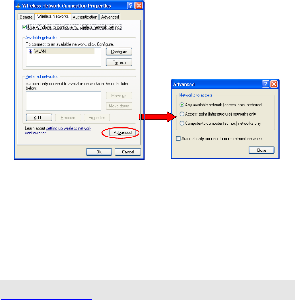
To Access to Certain Wireless Network Type
The default network type of Windows XP Zero Configuration is any available access points (Access
Point mode) or WLAN Card equipped computer (Ad-Hoc mode) within the range at the given time.
However, you may wish to connect to a certain network type sometimes. To change the default settings,
click the Advanced button in the Wireless Network Connection Properties dialog box.
M033103V10
22
Figure 3-8 The Advanced Dialog Box:
The open Advanced dialog box provides three options, Any available network, Access point
networks only, and Computer-to-computer networks only. Choose either one of them according to
your need, and then click Close to finish. Then you will find under the Available networks area in the
Wireless Network Connection Properties dialog box, only the specified networks are displayed.
Note: If you wish to use the attached application –PRISM Configuration Utility of the 802.11b WLAN USB
Module instead of Windows XP’s Wireless Zero Configuration, please check “step k” under 2.4 Installation
Procedures for Windows XP Users in this manual to change the settings.
M033103V10
23
4
4.
.
P
PR
RI
IS
SM
M
C
CO
ON
NF
FI
IG
GU
UR
RA
AT
TI
IO
ON
N
U
UT
TI
IL
LI
IT
TY
Y
B
BA
AS
SI
IC
CS
S
After successfully installing the driver for your 802.11b Wireless LAN USB Module on your computer,
you may see the PRISM Configuration Utility icon, , displayed in the system tray. To set
configurations for your USB Module, simply double-click on the icon to open the PRISM Wireless
Settings dialog box, in which four tabs are contained, including Status, Configuration, Encryption,
and About. Each of them proffers different functions to assist you in configuring the connection to the
networks.
In this chapter, three topics are offered: Tray Icon, Right-click Menu of the Tray Icon, and The Utility
Function. Please refer to the preferred topic to obtain more information and enjoy vast advantages
PRISM Configuration Utility brings.
4.1 Tray Icon
As long as you finish installing PRISM Configuration Utility on your computer system, you will see
the PRISM Configuration Utility icon, , shown at the right bottom corner of your screen. When you
move the mouse cursor over it, the current link quality is provided in the tips.
Furthermore, the color of the icon varies with the current state of your network connection. Check the
list below to learn the definition of each color.
Icon Quality
Excellent Link Quality 100%
Data Frame Errors – Check WEP Settings
Not Linked
Radio Off
Note: The blue icon indicated that you might have entered incorrect WEP keys. To solve the problems, choose
the Configuration tab in the PRISM Wireless Settings dialog box to correct the keys for encryption.
4.2 Right-click Menu of the Tray Icon
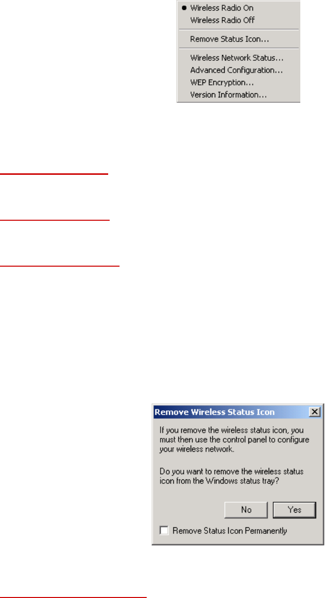
Right-click the PRISM Configuration Utility icon, , in the system tray will open a menu as the
following picture:
M033103V10
24
Figure 4.2-1: Right-click Menu of the Tray Icon
Check the descriptions below to obtain detailed information about each command in the menu.
Wireless Radio On
Choose the Wireless Radio On command to receive the radio frequency signal.
Wireless Radio Off
Choose Wireless Radio Off command will stop receiving the radio frequency signal.
Remove Status Icon
If you don’t wish to have the PRISM Configuration Utility icon displayed in the system tray, choose
this command to open the Remove Wireless Status Icon dialog box, and then choose Yes to have
the icon disappeared. The icon will reappear next time when you restart the computer. If you intend to
remove it permanently, put a tick in the checkbox next to the Remove Status Icon Permanently
option. To launch the utility hereafter, click Start on the taskbar, choose Program from the menu, and
then point to PRISM Configuration Utility from the submenu of WLAN PRISM Utility. Clicking No will
undo the removal.
Figure 4.2-2: The Remove Wireless Status Icon Dialog Box
Wireless Network Status
Choose this command to launch the Status tab of the PRISM Wireless Settings dialog box. For more
details about the tab, please refer to The Status Tab in The Utility Function section below.
M033103V10
25
Advanced Configuration
Choose this command to launch the Configuration tab of the PRISM Wireless Settings dialog box.
Please refer to The Configuration Tab in The Utility Function section below to gain more information
about the tab.
WEP Encryption
Choose this command to launch the Encryption tab of the PRISM Wireless Settings dialog box. This
tab offers you various options to maintain the secure management in a wireless LAN environment. See
the explanations in The Encryption Tab of The Utility Function section below for more details.
Version Information
Choose this command will launch the About tab of the PRISM Wireless Settings dialog box. The
About tab reveals general information on your USB Module, including the release version of driver and
the PRISM Configuration Utility, and the module’s MAC Address.
4.3 The Utility Function
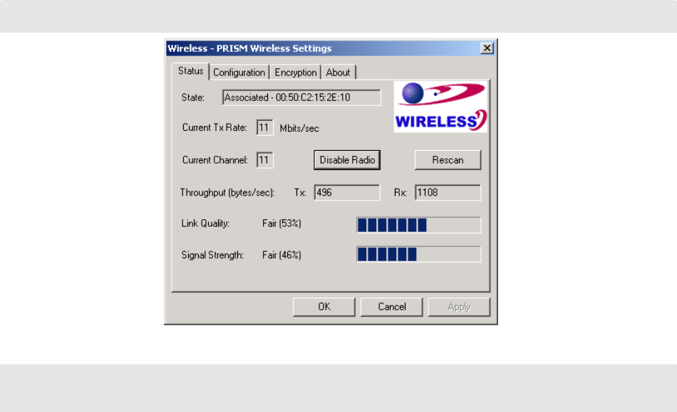
When you double-click the PRISM Configuration Utility tray icon, the PRISM Wireless Settings
dialog box will be prompted as the picture shows below. The application is a window-based program,
which is consisted of four tabs, including Status, Configuration, Encryption, and About.
Figure 4.3-1: The PRISM Wireless Settings Dialog Box
Check the desired items below to obtain more details about them.
The Status Tab
In the PRISM Wireless Settings dialog box, click the Status tab, and you will see the following display.
Here presents the status of your current connection. To close the window, click OK.
M033103V10
26
Note: Choose the Wireless Network Status command from the right-click menu of PRISM Configuration
Utility tray icon will launch this tab too.
Figure 4.3-2: The Status Tab
Note: The texts before ”PRISM Wireless Settings” in the caption bar of the dialog box is the profile name of the
current connection. Thus, the caption contexts vary according to the connectivity at the given time. Take the
picture above for example; the associated profile is named “Wireless”.
From the window, the general information on the status of currently connected entry is presented. You
may want to click the Rescan button to reinitiate the scanning process and update the status. Later the
result of scanning will be renewed and displayed in the window afterwards. If you wish to stop the
networking connection, click the Disable Radio button to stop scanning. However, if you are already in
the disabled radio mode, you will find the Enable Radio button here instead. Click Enable Radio to
regain the link then.
State
Here displays the MAC Address of the current associated entry, which could be a connected access
point in the Infrastructure mode or computers joining in the Ad-Hoc network.
Current Tx Rate
This feature indicates the transmission rate of the current connection.
Current Channel
Here reveals the current channel operated in the wireless network. Note that the channel number
differs as the radio scans any available channels in the Infrastructure mode.
Throughout (bytes/sec)
This feature indicates the rates of transmitting (Tx) and receiving (Rx) data package of your USB
module within a short period of time; thus, the values vary on a time basis.
M033103V10
27
Link Quality
Link Quality is based on the percentage of successfully transmitted or received signal of the
associated access point beacon within a limited period. The higher the percentage, the better the
link quality. The bar graph beside also provides a visual interpretation of the current link quality. It is
note that the Link Quality and Signal Strength features only apply to the infrastructure mode. They
are inapplicable in the Ad-Hoc mode since data will be transferred from many different computers.
Signal Strength
You may learn the received signal strength of the baseband processor of the Beacon signal from the
Signal Strength bar beside, and it’s also presented in terms of percentage. As the signal gets
stronger, you will see the signal percentage rate gets higher. It is noted that the Signal Strength and
Link Quality features only apply to the Infrastructure mode. They are inapplicable in the Ad-Hoc
mode since data will be transferred from many different computers.
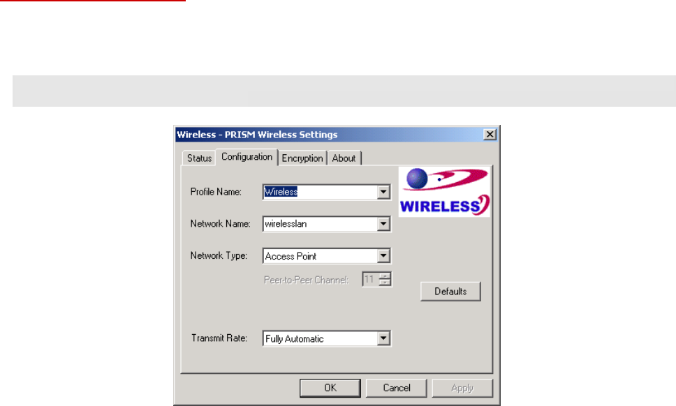
The Configuration Tab
Click this tab to save different profiles for different network configurations. When finish changing the
settings, please click Apply to perform the new configuration at last.
Note: Choose the Advanced Configuration command from the right-click menu of PRISM Configuration
Utility tray icon will launch this tab too.
Figure 4.3-3: The Configuration Tab
Profile Name
Enter texts in the Profile Name field to identify a new profile. After defining the configurations below,
click the Apply button to establish the profile. To switch between any existing profiles, simply click
the arrow button at the right of the Profile Name field to open the pull-down menu and then select
the intended one from it.

M033103V10
28
Note: You will have at least one profile named ANY, which allows a link with an Access Point or another
Wireless LAN PC Card equipped computer at the given time. When you click the Defaults button under the
tab, a profile of the current connection is created.
Network Name
Network Name is also known as SSID, standing for Service Set Identifier, must be unique to
distinguish itself as a particular wireless network, and all wireless points in this network area share
the same SSID. Type the identical SSID in the Network Name field to associate with access points
or stations within the specified wireless LAN. To change the Network Name, highlight the name in
the box, edit a new SSID, and then click Apply to save the changes.
Network Type
Two network types are offered here: Access Point and Peer-to-Peer. Choose the intended type
from the two options. The Access Point mode, which is also known as the Infrastructure mode,
allows you to communicate with a wired network via an access point. If you attempt to operate this
mode, you must indicate the identical Network Name to make a communication with the intended
access point. On the other hand, the Peer-to-Peer mode provides you with the so-called Ad-Hoc
communication, which means each wireless-equipped computers within a group is able to connect
others as an independent wireless LAN without the use of an access point. Each station within this
Ad-Hoc network has to define the same Network Name and Peer-to-Peer Channel.
Peer-to-Peer Channel
This command is only available while you are operating the Peer-to-Peer mode, the so-called
Ad-Hoc mode. Specify the operating radio frequency channel from the pull-down menu. Note that
the available channels differ from country to country, and the channel number must be the same
between the entries/stations within the range, so that each can communicate with the others. While
in the Access Point mode, the channel number would be the same as the associated access point.
Thus, there’s no need to manually set up the value.
Transmit Rate
This command allows you to indicate the rate of transferring the data packet from the associated
access point or any nodes within the range. There are four options for you: Auto 1 or 2 Mb, 5.5 Mb,
11 Mb, and Fully Automatic. Specify the rate according to the speed of your wireless network from
the provided options, or you may simply choose Fully Automatic to set the best available rate
according to the received signal quality and the capabilities of the associated access point or station.
The Encryption Tab
Click the Encryption tab to define the encryption settings for a specific profile. It offers you various
options concerning the so-called WEP (Wired Equivalent Privacy) to maintain the secure management
in a wireless LAN environment. See the explanations below for more details, and before making an
activation of any new settings, click Apply. To leave the window, click OK. To undo the new settings,
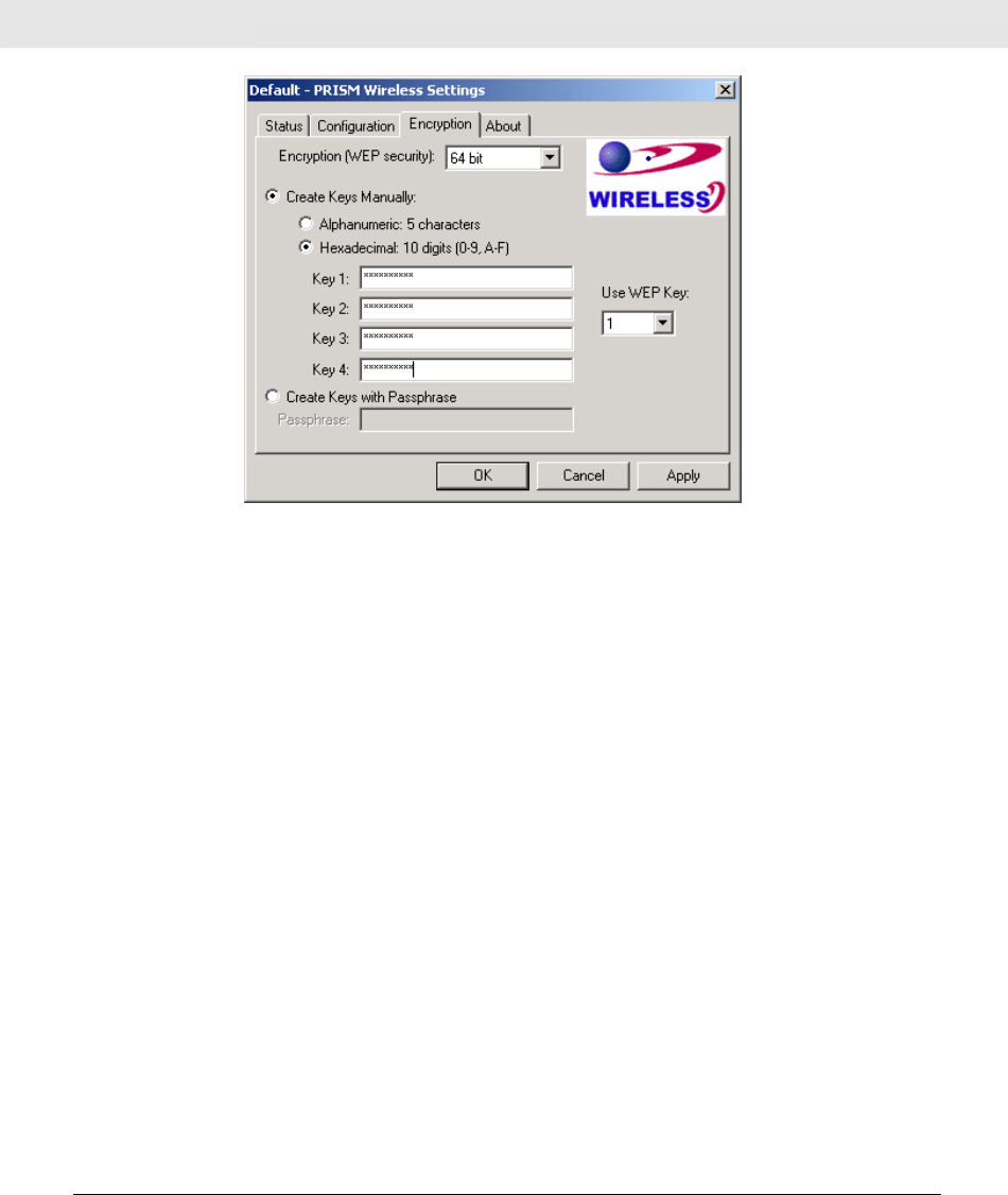
M033103V10
29
select the Cancel button.
Note: Choose the WEP Encryption command from the right-click menu of PRISM Configuration Utility tray
icon will launch this tab too.
Figure 4.3-4: The Encryption Tab
Encryption (WEP security)
If you choose Disabled from the pull-down list, you will have the wireless module communicated
with all stations within the same networking community without any data encryption. Otherwise, two
key lengths are offered: 64 bit and 128 bit. Specify a preferred one from the two, so that you may
use the identical WEP key to make a communication with the chosen access point.
Create Key Manual
Once you set the Encryption type as 64 bit or 128 bit, you may choose to edit WEP keys manually
or create them via the passphrase of your wireless network. If you choose the Create Key Manual
option, you may directly enter up to 4 WEP keys for use in WEP encryption. To generate the WEP
keys, please define the key entry method as Alphanumeric or Hexadecimal (for hexadecimal
characters, only digits 0-9 and letters A-F are valid). Then edit the texts in the blank fields below,
from Key 1 to Key 4, as the encryption codes. Note that these codes/keys shall be identical between
the wireless nodes within the range and the access point only. Check the table below to see valid
key length for each encryption type:
64 bit 128 bit
Alphanumeric 5 characters 13 characters
Hexadecimal 10 digits 26 digits
Use WEP Key
Indicate which WEP key you intend to apply to activate the WEP encryption from the pull-down
M033103V10
30
menu. Make sure that the intended access point on the wireless network shares the same keys. By
default, Key 1 will be used.
Create Keys with Passphrase
Choose this command when the associated wireless network uses a passphrase to create WEP
keys. Enter the passphrase stings in the Passphrase filed to generate four encryption keys in the
Key fields above. Note that only letters A-F are valid for the Passphrase feature.
After finish configuring the Encryption features, remember to click the Apply button to initiate the new
settings.
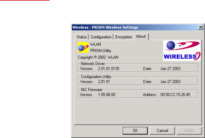
The About Tab
This tab reveals general information on your wireless LAN USB module, including the following items:
Figure 4.2-14: The About Ta b
Network Driver
Displays the current version and released date of the 802.11b Wireless LAN USB Module’s driver.
Configuration Utility
Displays the current version and released date of the PRISM Configuration Utility application.
NIC Firmware
Displays the current NIC card firmware version and the MAC (Media Access Control) address of
your wireless card. It is consisted of 12-digit hexadecimal numbers (48 bits in length) to identify your
computer's physical address on the local area network.

M033103V10
31
A
AP
PP
PE
EN
ND
DI
IX
X
A
A:
:
T
TR
RO
OU
UB
BL
LE
ES
SH
HO
OO
OT
TI
IN
NG
G
This section provides solutions to problems that you might encounter during the installation and
operation of your 802.11b WLAN USB Module. Please refer to the desired topics below and read the
description to solve your problems.
Uninstall RRISM Configuration Utility and the Module’s Driver
Prior to starting the uninstalling, please make sure that the utility is closed, and then go along with the
procedures below to entirely uninstall RRISM Configuration Utility and the module driver.
1. Click on
Start on the taskbar to select Programs.
2. From the
Programs menu, find RRISM Configuration Utility, and then choose Uninstall
RRISM Configuration Utility from the submenu.
3. Click
OK to begin removing the driver files from your PC.
4. Follow the on-screen instructions to finish the removal of program.
The 802.11b WLAN USB Module Does Not Work Properly
If this happens, follow the guidelines below.
1. Right-click the
My Computer desktop icon, and choose Properties to open the
System Properties dialog box.
2. If you are under Windows 98 or Me, choose the Device Manager tab, or if your system
is Windows 2000 or XP, click the Hardware tab, and then choose the Device Manager
button.
3. In the opened window, find your USB module to see if the installation is successful. If
you see a yellow exclamation mark beside the item, please go along with the steps
below to reinstall the drivers:
4. Uninstall the software and hardware drivers from your PC. (Please refer to the previous
topic for details)
5. Restart your computer and repeat the installation procedures as this manual indicated
in Chapter 3: Installation of the 802.11b Wireless LAN USB Module.
6. When finished, open the Device Manager window again to verify if the installation is
approved. The yellow exclamation mark shall be removed for this time.
Upgrade RRISM Configuration Utility and the Module’s Driver
To upgrade the drivers for RRISM Configuration Utility and the 802.11b Wireless LAN USB Module,
follow the procedures below. Please note that the details might be slightly different according to the
Windows system you are using. Here we are taking the example of Windows 2000.
1. Click
Start on the taskbar and choose Control Panel from the Settings menu.
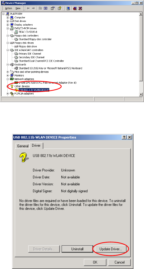
M033103V10
32
2. Select
System to open the System Properties dialog box, and then under the
Hardware tab, click the Device Manager button to open the Device Manager dialog
box.
3. Double-click the
Other devices item in the list to show the USB 802.11b WLAN
DEVICE icon, which is displayed with a yellow icon beside. Right-click the icon and
choose Properties from the opened menu.
Figure 5-1: The Device Manager Dialog Box
4. In the opened dialog box, click the Update Driver button under the Driver tab.
Figure 5-2: The Driver Tab
M033103V10
33
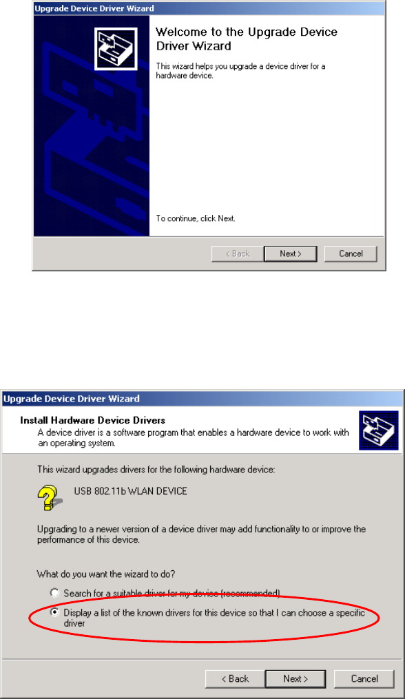
5. Click
Next in the Upgrade Device Driver Wizard dialog box to continue.
Figure 5-3: The Upgrade Device Driver Wizard Dialog Box
6. On the Install Hardware Device Drivers screen, choose Display a list of unknown
drivers for this device so that I can choose a specific driver. Click Next then.
Figure 5-4: The Install Hardware Device Drivers Screen
7. Choose Network adapters on the Hardware Type screen, and then click Next.
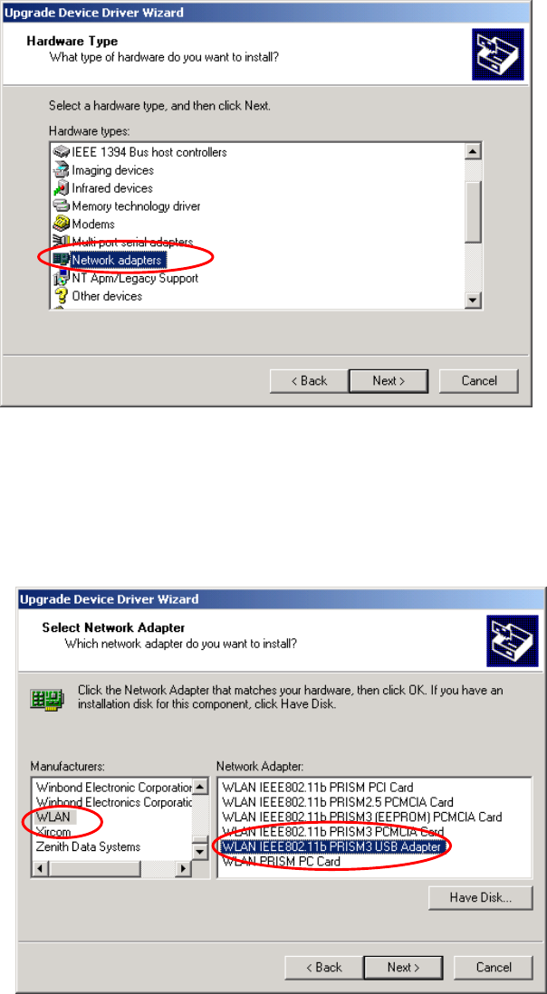
M033103V10
34
Figure 5-5: The Hardware Type Screen
8. On the
Select Network Adapter screen, choose WLAN under Manufacturers and
WLAN IEEE802.11b PRISM3 USB Adapter under Network Adapter, and click Next to
proceed.
Figure 5-6: The Select Network Adapter Screen
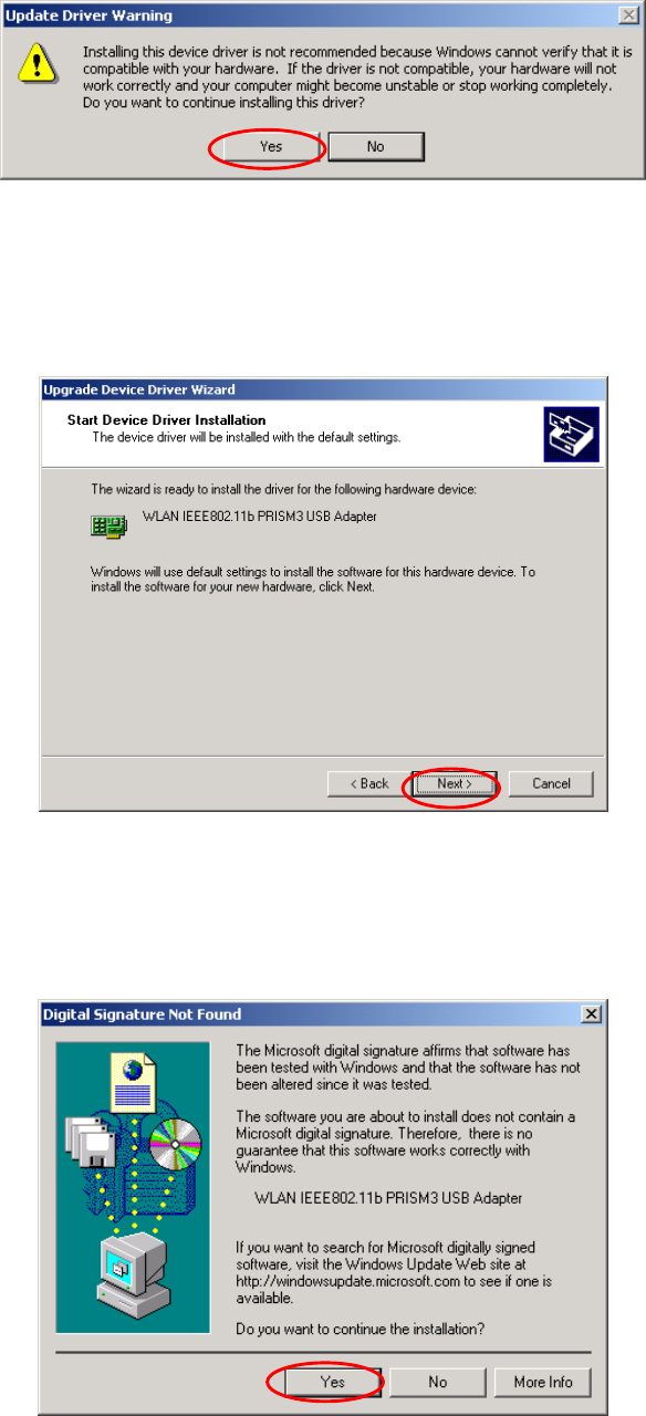
9. When the
Update Driver Waning message box appears, click Yes.
M033103V10
35
Figure 5-7: The Update Driver Waning Message Box
10. The
Start Device Driver Installation screen will be displayed to notify that the wizard is
ready to upgrade the driver for the hardware device. Choose the Next button.
Figure 5-8: The Start Device Driver Installation Dialog Box
11. In the prompted
Digital Signature Not Found dialog box, click Yes to let 802.11b
Wireless LAN USB Module be verified to run on Windows 2000
Figure 5-9: The Digital Signature Not Found Dialog Box
M033103V10
36
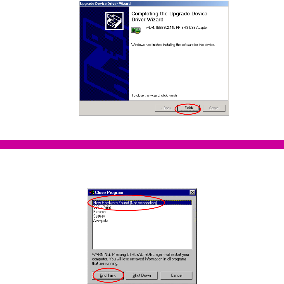
12. Click
Finish when you see the following window. The driver and software installations
are entirely complete at the time.
Figure 5-10: The Complete Screen
For Windows 98: Close the Close Program Dialog Box During the Installation
If you are using Windows 98, during the installation process, you might be notified with the Close
Program dialog box after indicating the Windows to install the required files on the Windows 98
CD-ROM.
Figure 5-11: The Close Program Dialog Box
This is however normal. The dialog box displays a list of all presently active programs. Choose New
Hardware found [Not responding], and then click the End Task button. Then you can monitor and
configure the network via PRISM Client Utility according to your needs.

M033103V10
37
A
AP
PP
PE
EN
ND
DI
IX
X
B
B:
:
S
SP
PE
EC
CI
IF
FI
IC
CA
AT
TI
IO
ON
NS
S
Product Name 802.11b 11 Mbps WLAN USB Module
Model Name WM168b
Host Interface Std. USB 1. 1 I/F
Dimensions 25 (W) x 60 (L) x 4.3 (H) mm
Weight 7.5g
Frequency Band 2.400 ~ 2.4835GHz (subject to local regulations)
Number of Channel 11 channels (US, Canada); 13 channels (ETSI); 14 channels (Japan)
Operating Voltage 3.3V ± 5%
Current Consumption Tx: 300mA / Rx: 285mA / Standby: 38mA / Sleep: < 1mA
Spreading DSSS (Direct Sequence Spread Spectrum)
Data Rate 11Mbps, 5.5Mbps, 2Mbps, 1Mbps
Transmit Power Typ. 15 dBm @ Nominal Temperature Range
Receive Sensitivity 11 Mbps @ -82 dBm, Typical
Modulation 11Mbps and 5.5Mbps CCK; 2Mbps: DQPSK; 1Mbps: DBPSK;
Security 64/128 bit WEP Encryption
Antenna Two GSC Type RF Connector
LED Indicator Defined By I/F Pin No. 5
Supplied Driver Windows 98SE/2K/Me/XP
Standards IEEE 802.11b Wi-Fi compliant
Media Access Protocol CSMA/CA with ACK
Warranty 1 year
Temperature Range 0 ~ 65°C (Operating), -20~70°C (Storage)
Humidity Max. 95% Non-condensing
Operating Range Open Space: 100 – 300m; Indoor: 40m – 100m
The transmission speed varies in the surrounding environment.
Roaming Full mobility and seamless roaming from cell to cell and across access
points
Network Protocol TCP/IP, IPX, NetBEUI
Management Utility Link Configuration for network join and diagnostics
Software Certification WHQL
EMC certification FCC, CE
Packaging Customer Define
CIS Customer Define

M033103V10
38
A
AP
PP
PE
EN
ND
DI
IX
X
C
C:
:
G
GL
LO
OS
SS
SA
AR
RY
Y
802.11b – 802.11b is one of the IEEE standards for wireless LANs and specifies a data transfer rate of
5.5 and up to 11 megabit per second in the 2.4 gigahertz radio band. 802.11b is recently given other
widespread names as Wi-Fi or Wireless Fidelity.
Ad-hoc Network - Ad-hoc network, also known as peer-to-peer network, means a wireless network
which is composed only of stations. This type of network is created with a group of wireless-equipped
computers. With the wireless devices, each computer, functioning as a server and a client at the same
time, can establish a LAN to directly communicate with other computers without any access points
involved. It is easy to set up a peer-to-peer network; however, because all stations must be within a
specific distance in order to be capable of communicating with each other, it is also limited. Thus, such
a type of network is widely used at small networking requirements, like between a few computers or
devices at departmental scales.
IEEE – IEEE, the Institute of Electrical and Electronics Engineers, is the world’s largest technical
professional society and is consisted of more than 366,000 members in approximately 150 countries.
As a leading authority on areas ranging from for computer engineering, biomedical technology and
telecommunications, IEEE endeavours to set more than 800 active consensus standards till now and
publish 30 percent of the world's literature in electrical engineering, computers and control technology.
Infrastructure Network – Infrastructure network allows you to communicate with wired LAN via an
access point. Unlike Ad-hoc network that all wireless-equipped stations within the range may directly
communicate with each other, clients of Infrastructure network can only transmit and receive data
through the use of a central access point. The associated access point also provides communication
with the wired network.
MAC Address – The MAC (Media Access Control) address is the serial number of your Network
Interface card. It has been burnt into the chip and could not be changed. MAC address is thus unique.
While a computer on the network is transferring data, its MAC address is also conveyed and attached
to be part of the header of the data packets.
Roaming – Roaming is an ability to allow users from one cell (or BSS) to another without losing
connection via a wireless device.
SSID – SSID is short for Service Set Identifier, a 32-character unique identifier for a workgroup of the
wireless network. An SSID of one WLAN should be different from that of others, so all access points
M033103V10
39
and other devices intending to communicate with a specific WLAN cannot achieve successful network
connectivity unless presenting the identical SSID. From some perspective, an SSID performs as a kind
of password to supply a measure of security on the WLAN. However, if an access point is set to
“broadcast” its SSID, this essential security is no longer remained. An SSID is also known as a
Network Name.
WEP - Wired Equivalent Privacy (WEP) is a security mechanism for wireless local area networks. It is
designed for 802.11 standard to offer an equal level of security as that of a wired LAN. Through the
configurations of encryption, WEP aims to provide security while the nodes with wireless devices are
transferring or receiving data packets over radio waves.
WLAN – Wireless local area network (WLAN) receive and transmit data over the air by using radio
frequency (RF) technology. The vital significance of WLAN is it minimizes the requirements for wired
connections and provides not only data connectivity but also user mobility. Without the constraint of
physical location, wireless LAN allows clients to transmit and receive data via high-frequency radio
waves rather than wires.
USB – USB, standing for Universal Serial Bus, was designed to make a connection between the
computer and its peripherals, such as keyboards, scanners, webcams, printers, etc., via an easy
operation of plug-and-play. USB has proved to be a good solution that allows users to quickly and
easily connect and add peripherals to computers. Through the USB interface, there’s even no need to
turn the computer off while adding a new peripherals mentioned above to a desktop or laptop computer.
Due to its convenience and simplicity, USB has won world-wide popularity, and most peripherals for
computers these days are designed for the USB standard.