AirWalk Communications AW96R19AB7 AW96R19AB7A01 Pico MiniCell User Manual
AirWalk Communications, Inc. AW96R19AB7A01 Pico MiniCell Users Manual
UserManual.wiki
>
AirWalk Communications
>
AW96R19AB7 User Manual
Users Manual
Navigation menu
Upload a User Manual
Namespaces
Wiki Guide
HTML
PDF
Info
Views
User Manual
Discussion / Help
Navigation
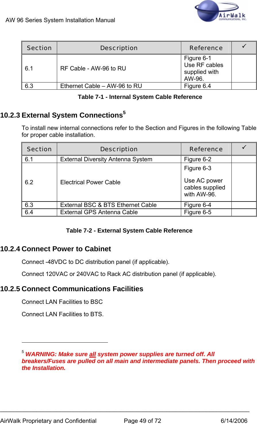
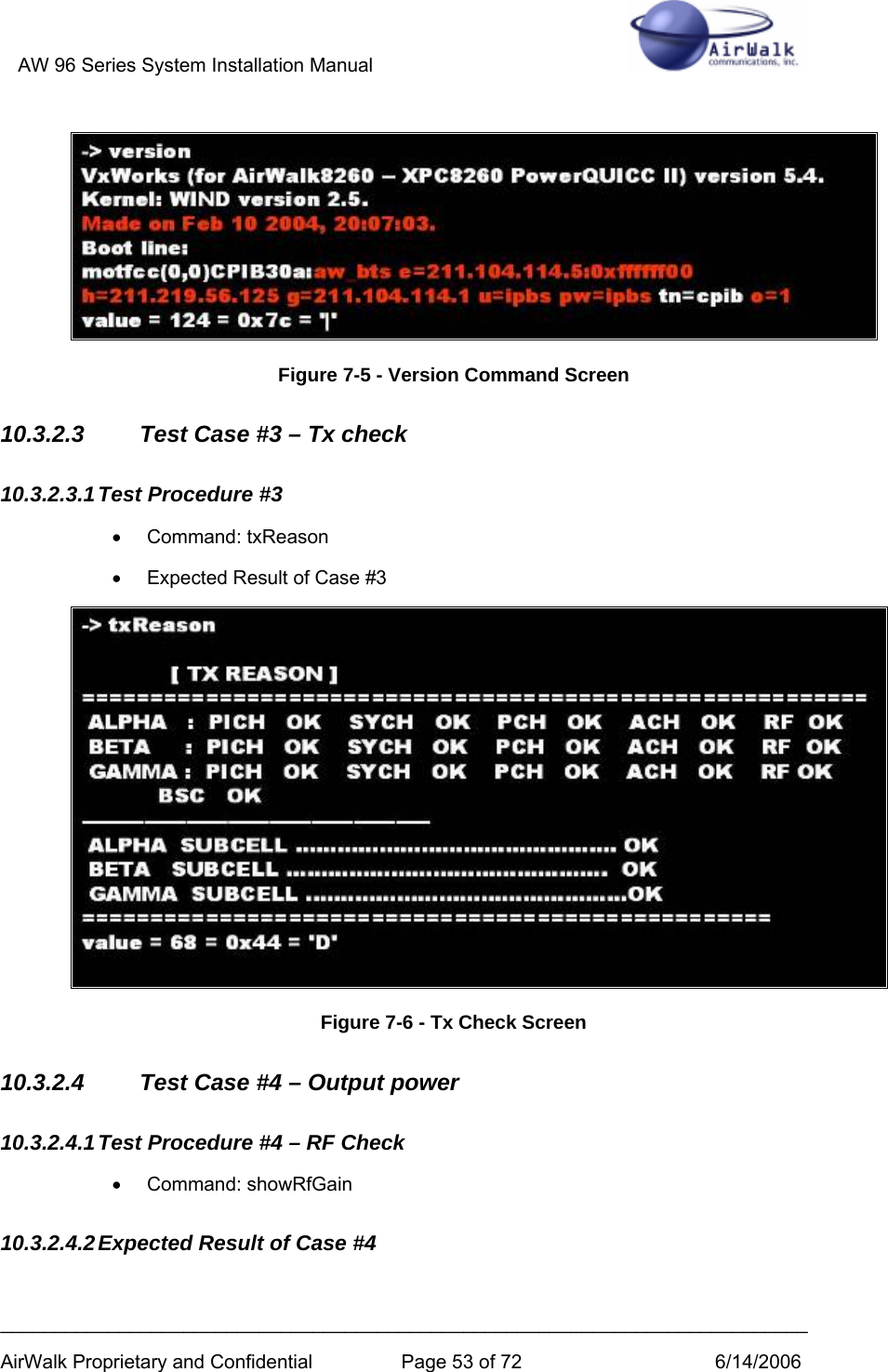
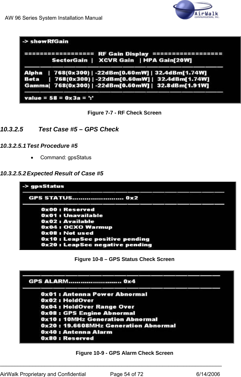
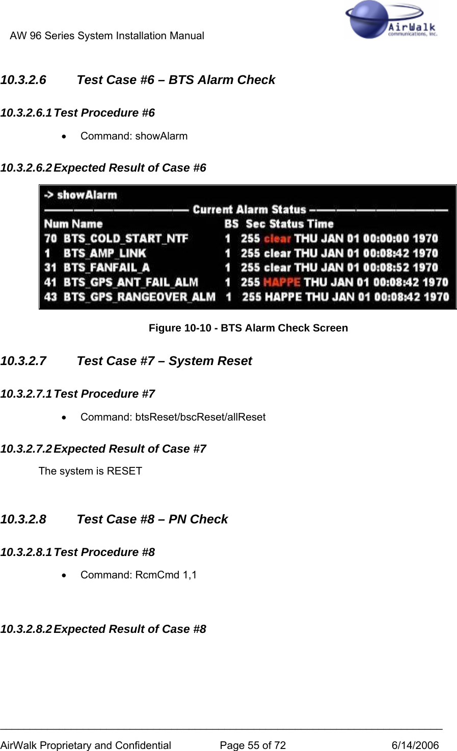
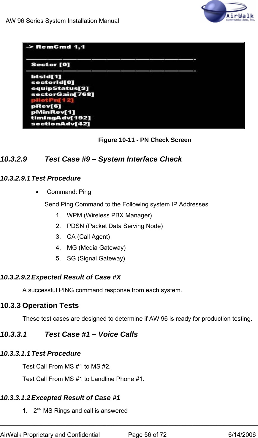
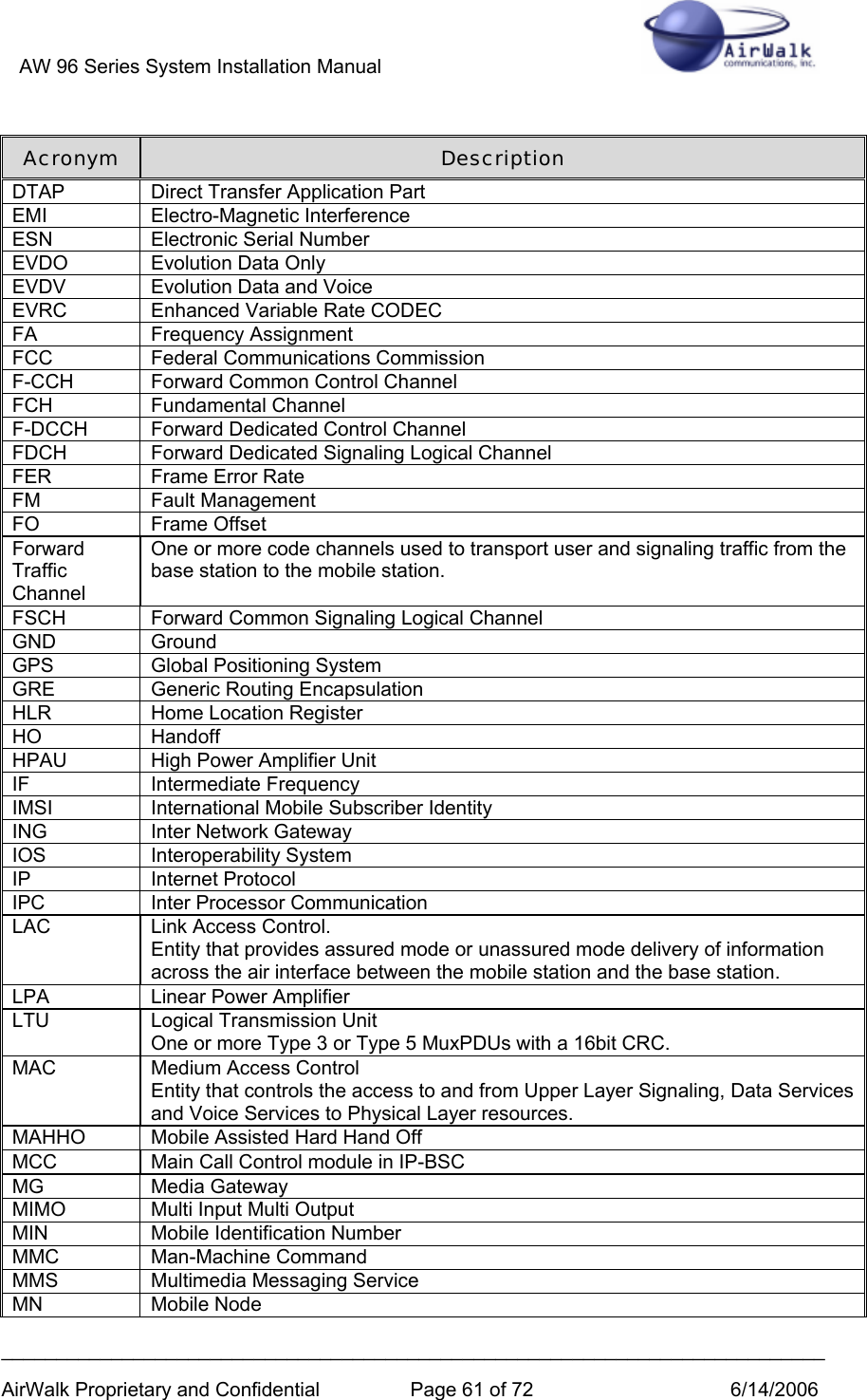
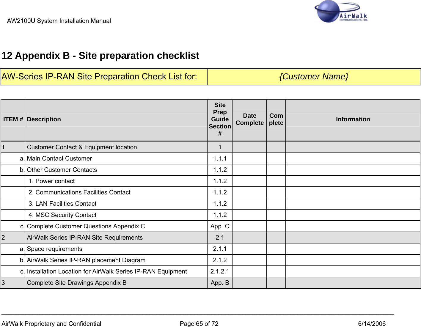
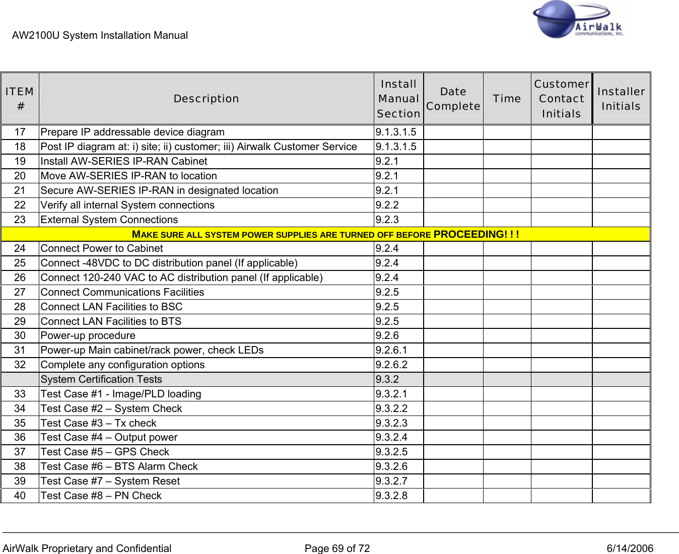
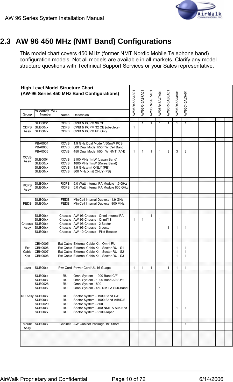
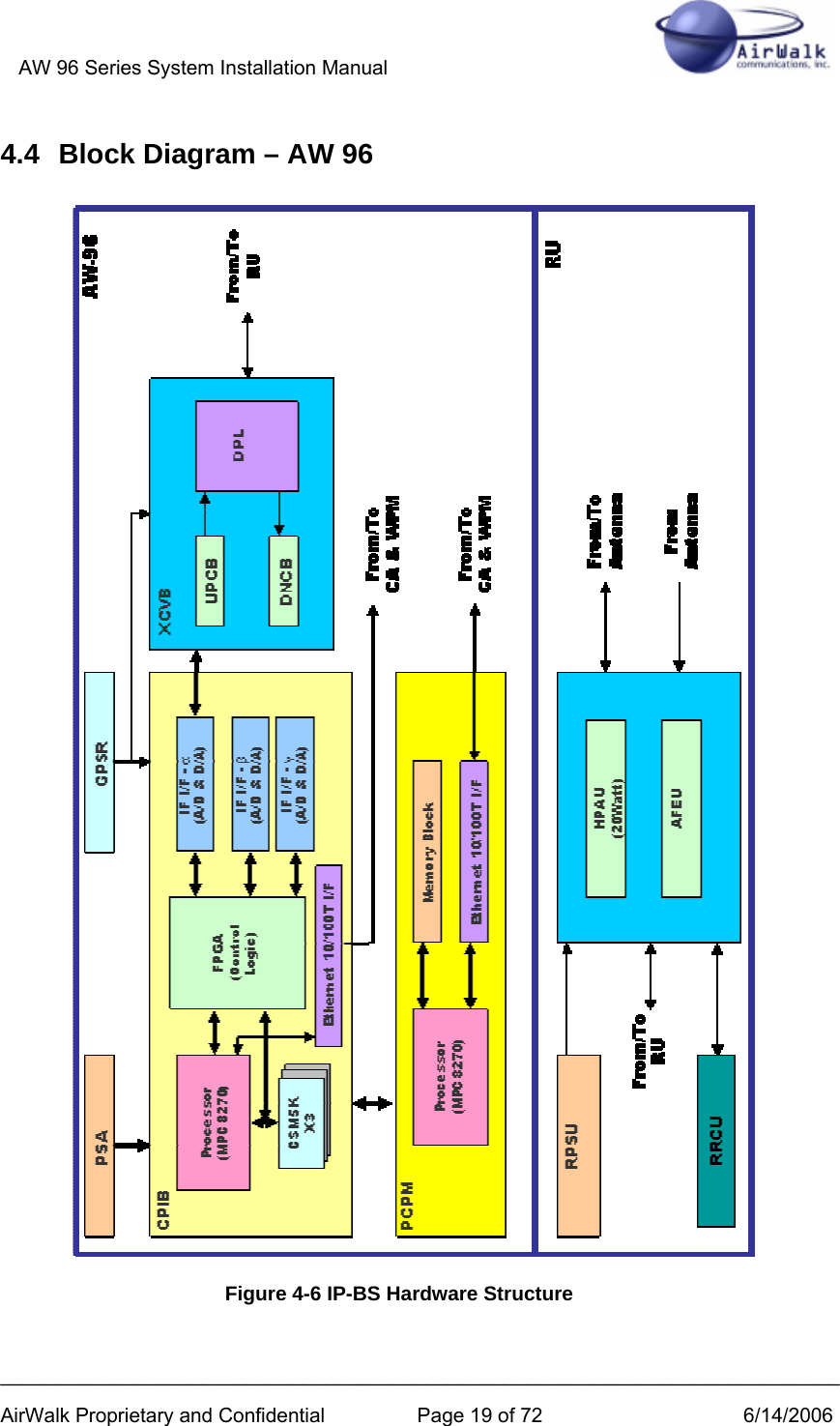
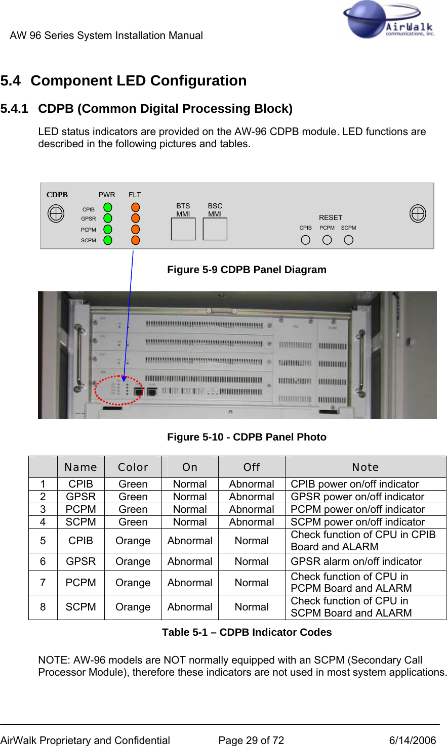
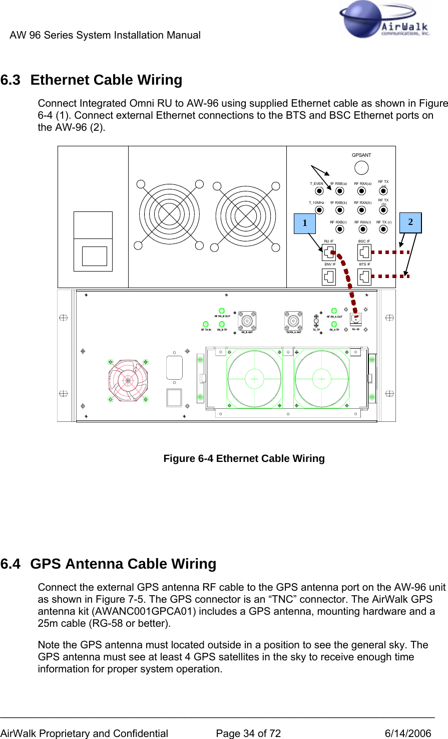
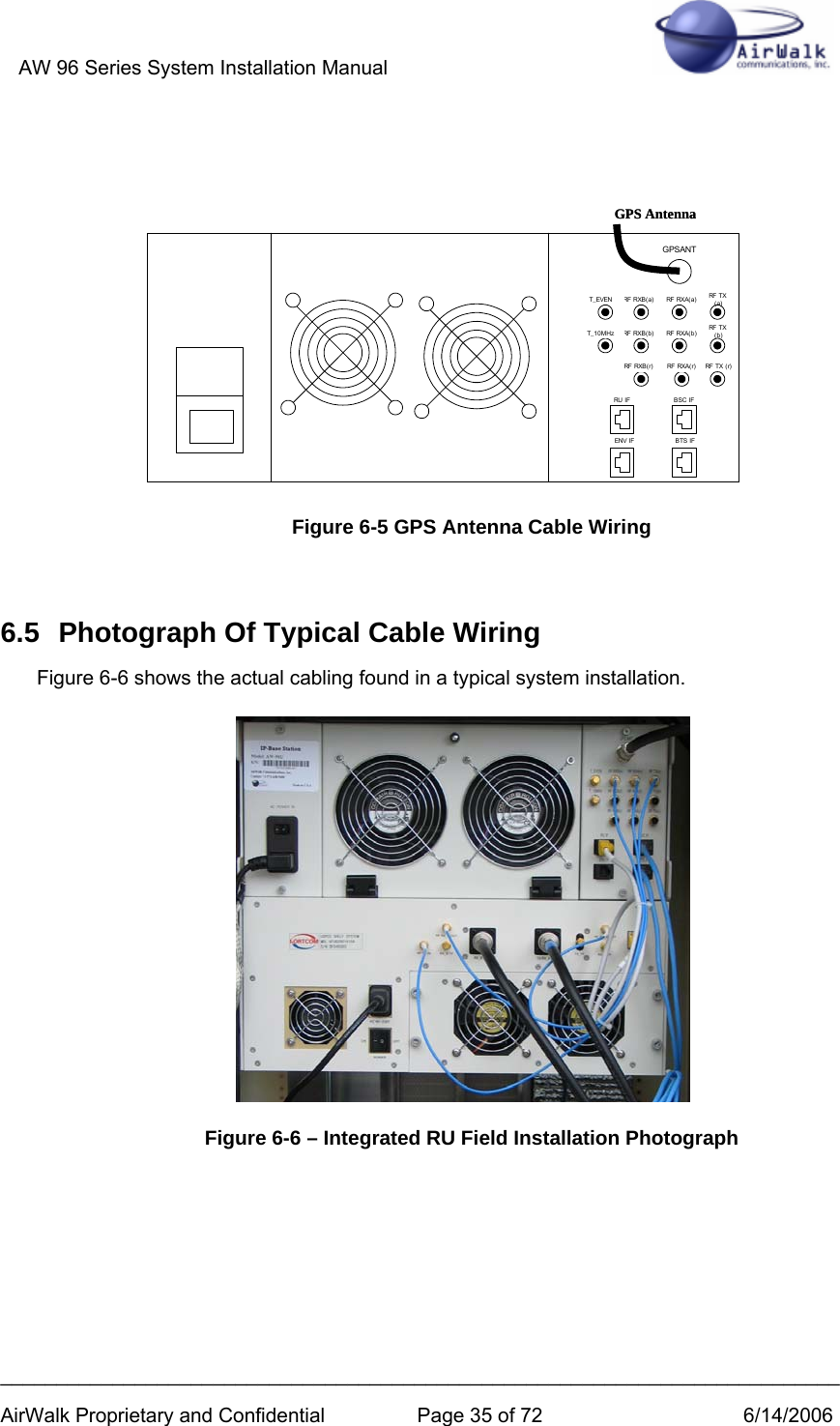
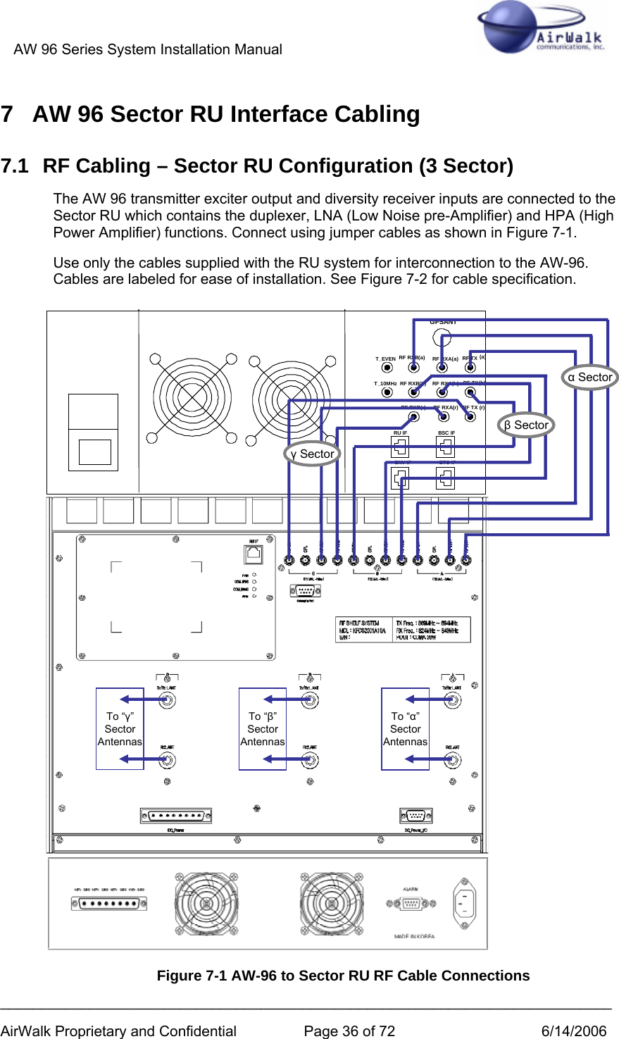
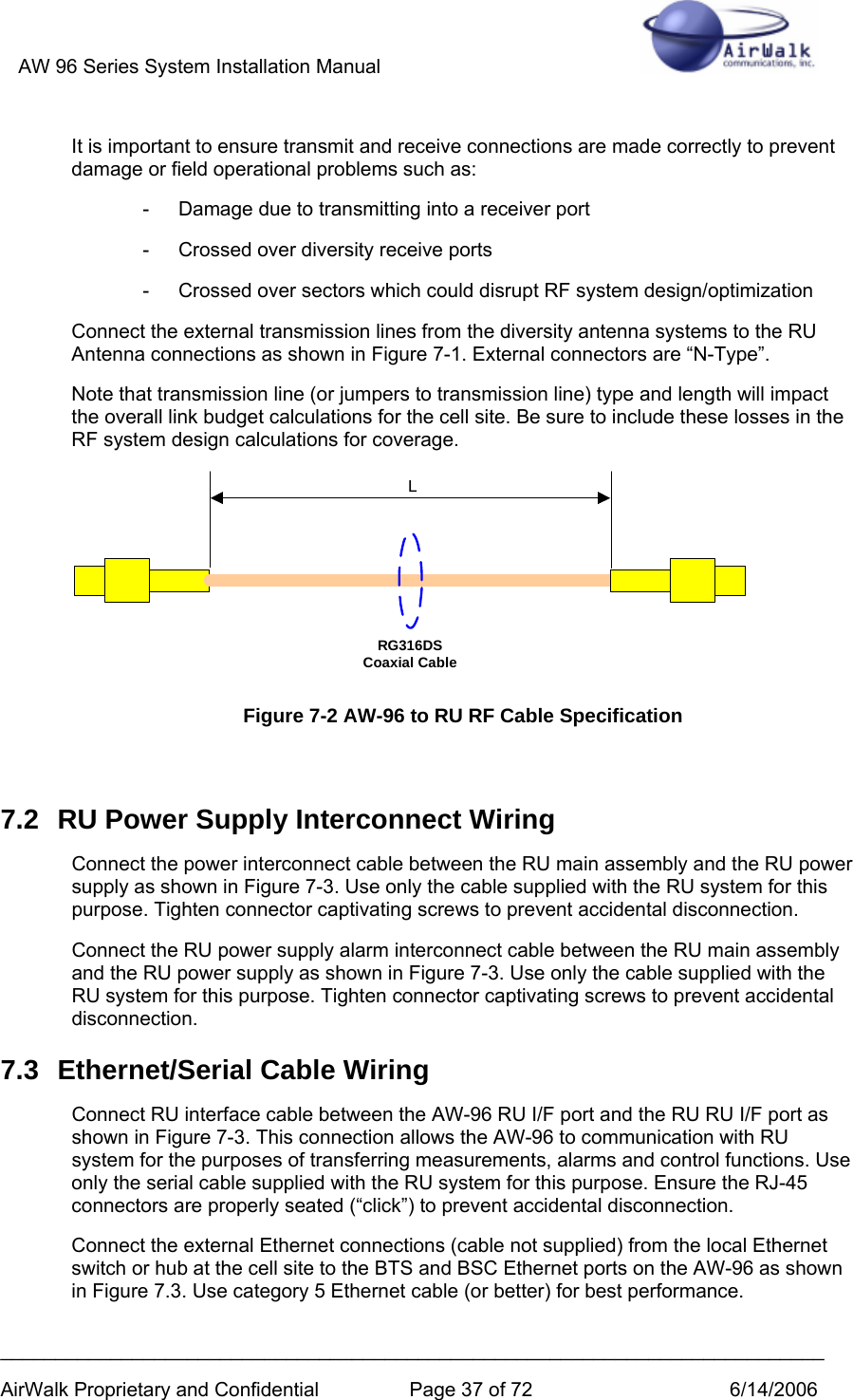
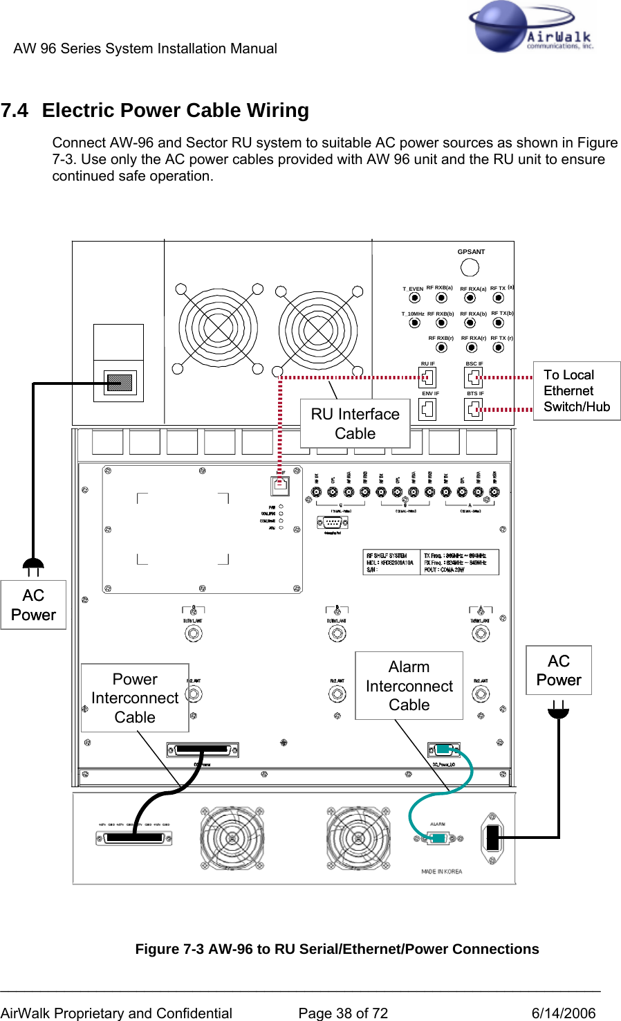
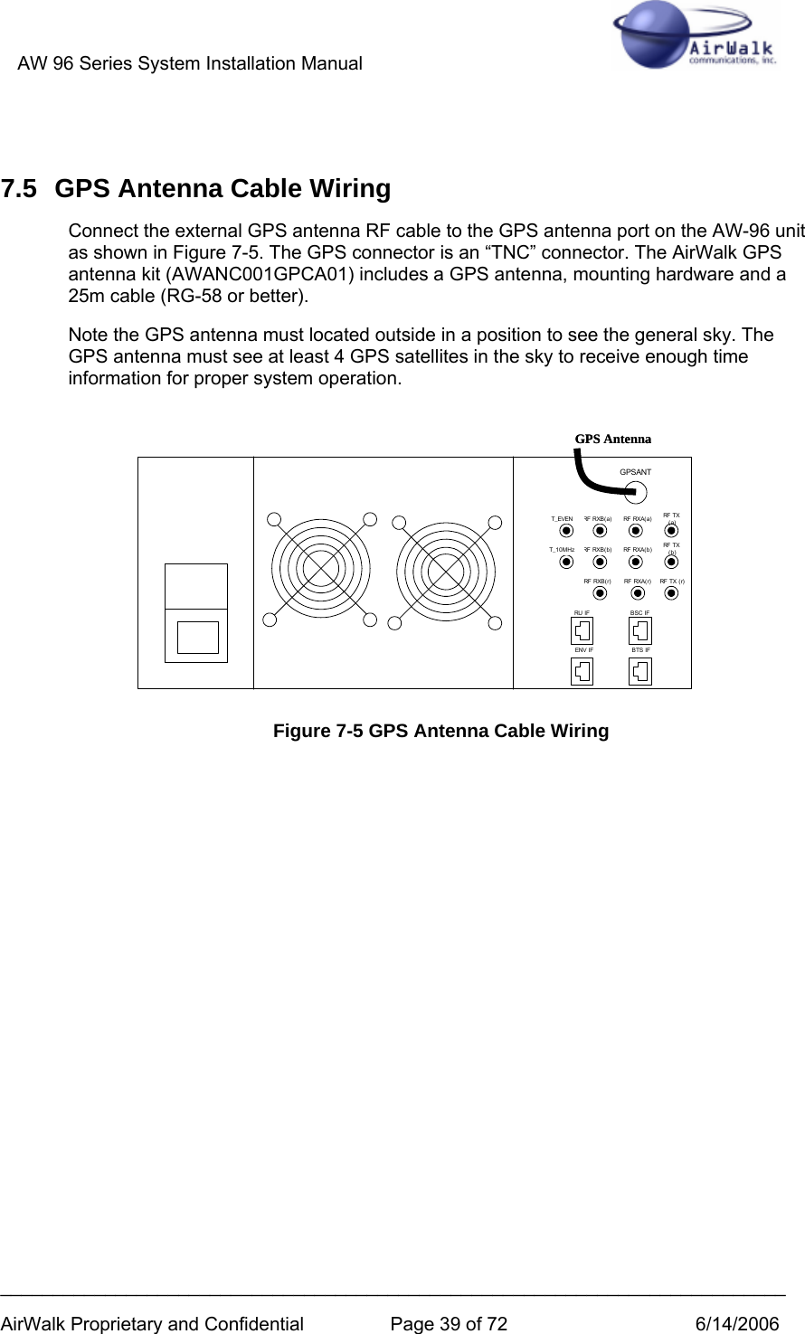
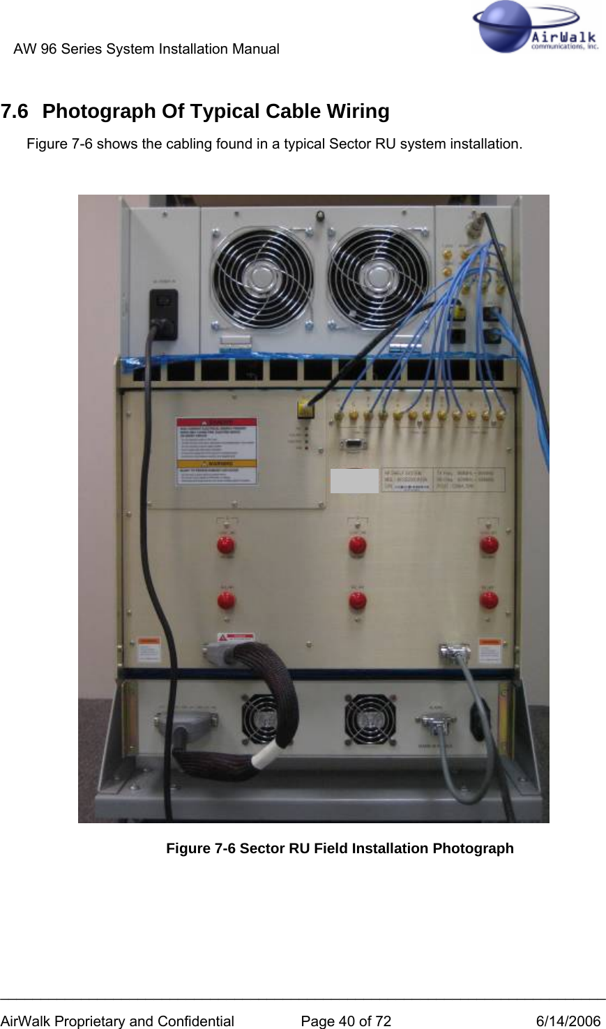
![AW 96 Series System Installation Manual ___________________________________________________________________________ AirWalk Proprietary and Confidential Page 4 of 72 6/14/2006 5 AW 96 COMPONENTS .........................................................................................................................24 5.1 AW-96 MAIN UNIT............................................................................................................................24 5.2 INTEGRAL OMNI RU (REMOTE RF UNIT) [OMNI CONFIGURATIONS].................................................25 5.3 SECTOR RU (REMOTE RF UNIT) [SECTOR CONFIGURATIONS]...........................................................26 5.4 COMPONENT LED CONFIGURATION ..................................................................................................29 5.4.1 CDPB (Common Digital Processing Block)..............................................................................29 XCVB.........................................................................................................................................................30 5.4.2 Sector RU Power Supply Unit (PSU) [AC powered models only] ............................................31 6 AW 96 INTEGRATED OMNI RU INTERFACE CABLING ............................................................32 6.1 RF CABLING – INTEGRATED RU OMNI CONFIGURATION...................................................................32 6.2 ELECTRIC POWER CABLE WIRING......................................................................................................33 6.3 ETHERNET CABLE WIRING.................................................................................................................34 6.4 GPS ANTENNA CABLE WIRING..........................................................................................................34 6.5 PHOTOGRAPH OF TYPICAL CABLE WIRING........................................................................................35 7 AW 96 SECTOR RU INTERFACE CABLING...................................................................................36 7.1 RF CABLING – SECTOR RU CONFIGURATION (3 SECTOR)..................................................................36 7.2 RU POWER SUPPLY INTERCONNECT WIRING .....................................................................................37 7.3 ETHERNET/SERIAL CABLE WIRING ....................................................................................................37 7.4 ELECTRIC POWER CABLE WIRING......................................................................................................38 7.5 GPS ANTENNA CABLE WIRING..........................................................................................................39 7.6 PHOTOGRAPH OF TYPICAL CABLE WIRING........................................................................................40 8 AW 96 LOW POWER (PICOCELL/MICROCELL) CABLING ......................................................41 9 FREQUENCY SETTING PROCEDURES ..........................................................................................42 9.1 BSM MANAGEMENT..........................................................................................................................42 9.2 LOCAL FA SETTING ...........................................................................................................................42 9.2.1 MMI Connection .......................................................................................................................42 9.2.2 FA Change Procedure...............................................................................................................43 10 INSTALLATION PROCEDURES....................................................................................................46 10.1 INSTALLATION VERIFICATION............................................................................................................46 10.1.1 Verify Customer Contact & Equipment location.......................................................................46 10.1.2 Uncrate and arrange for packing material disposal.................................................................47 10.1.3 Verify location of all Facility distribution points (main and intermediate)..............................47 10.2 AW-SERIES IP-RAN INSTALL PROCEDURES ...................................................................................48 10.2.1 Install AW-SERIES IP-RAN Cabinet.........................................................................................48 10.2.2 Verify All Internal System Connections.....................................................................................48 10.2.3 External System Connections....................................................................................................49 10.2.4 Connect Power to Cabinet ........................................................................................................49 10.2.5 Connect Communications Facilities..........................................................................................49 10.2.6 Power-up procedure..................................................................................................................50 10.3 SYSTEM TEST.....................................................................................................................................50 10.3.1 PC to AW 96 cable ....................................................................................................................50 10.3.2 System Certification Tests .........................................................................................................51 10.3.3 Operation Tests .........................................................................................................................56 10.3.4 Operator Specific Tests .............................................................................................................57 10.4 SITE CLEAN UP AND CUSTOMER SIGNOFF ..........................................................................................57 10.4.1 Dispose of all packing material.................................................................................................57](https://usermanual.wiki/AirWalk-Communications/AW96R19AB7/User-Guide-675039-Page-4.png)
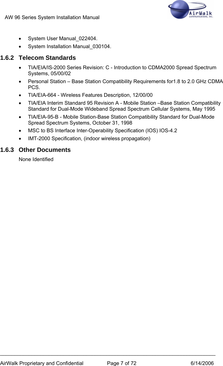
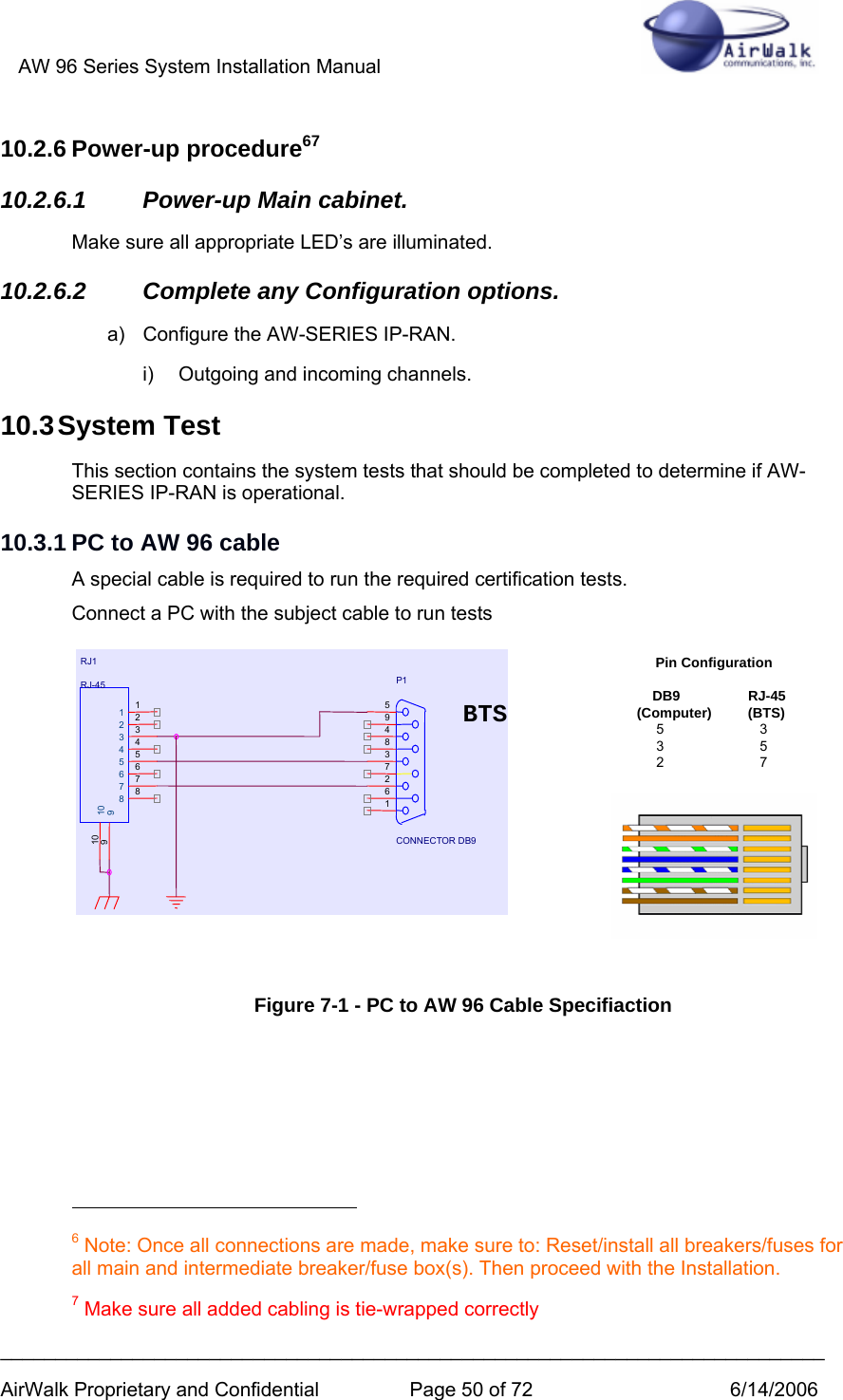
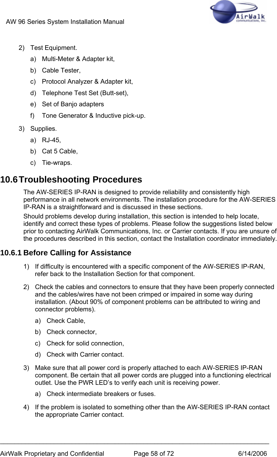
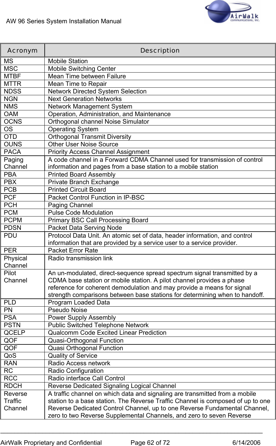
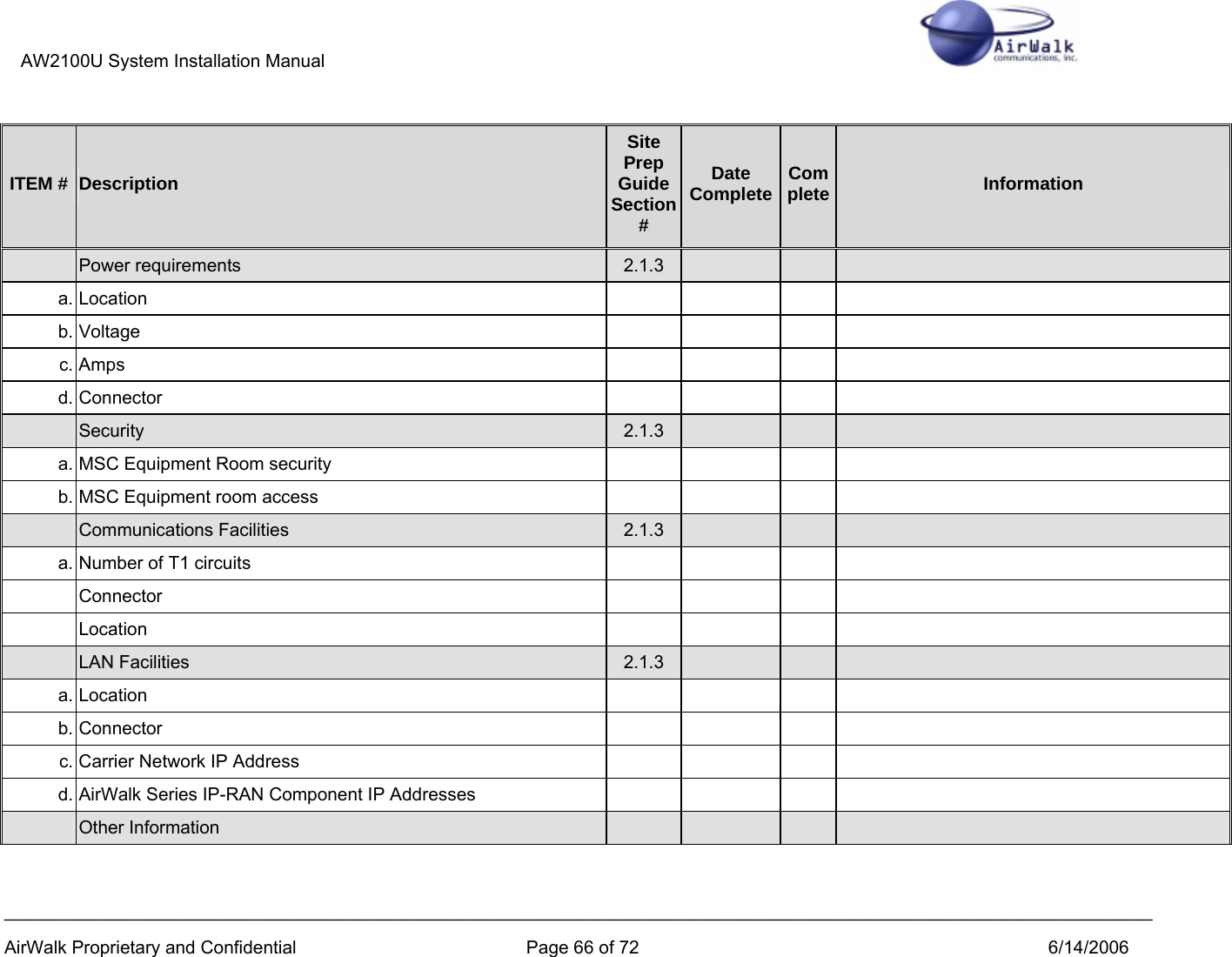
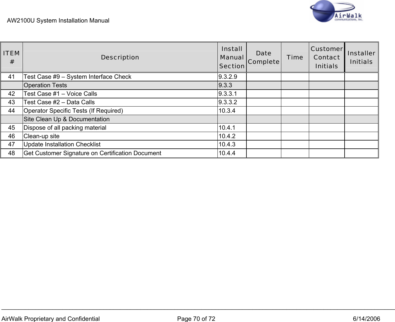
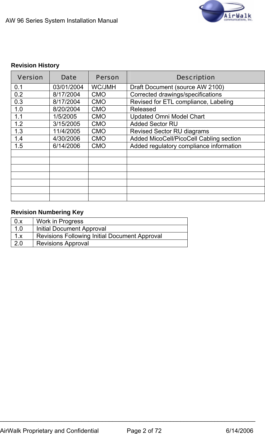
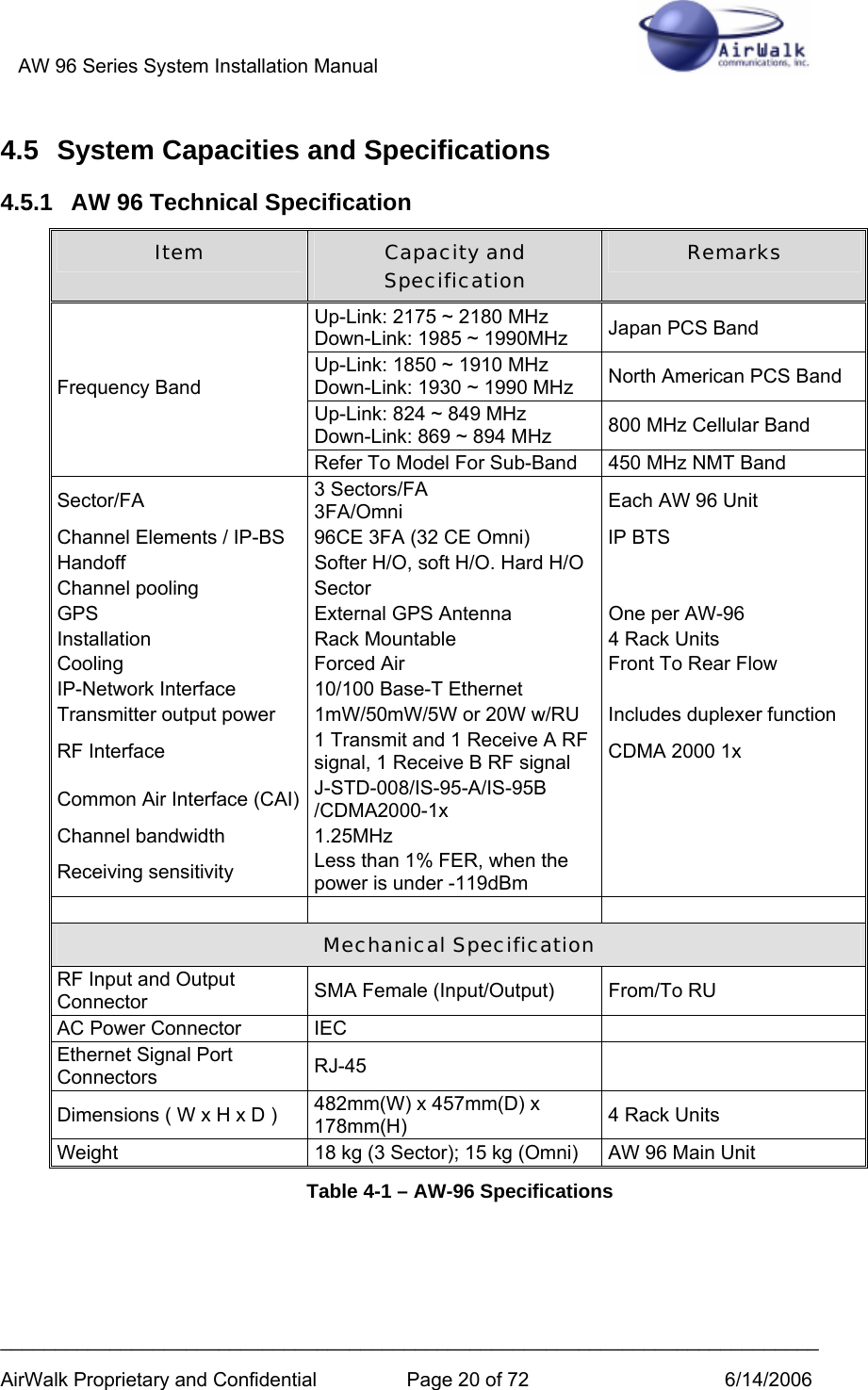
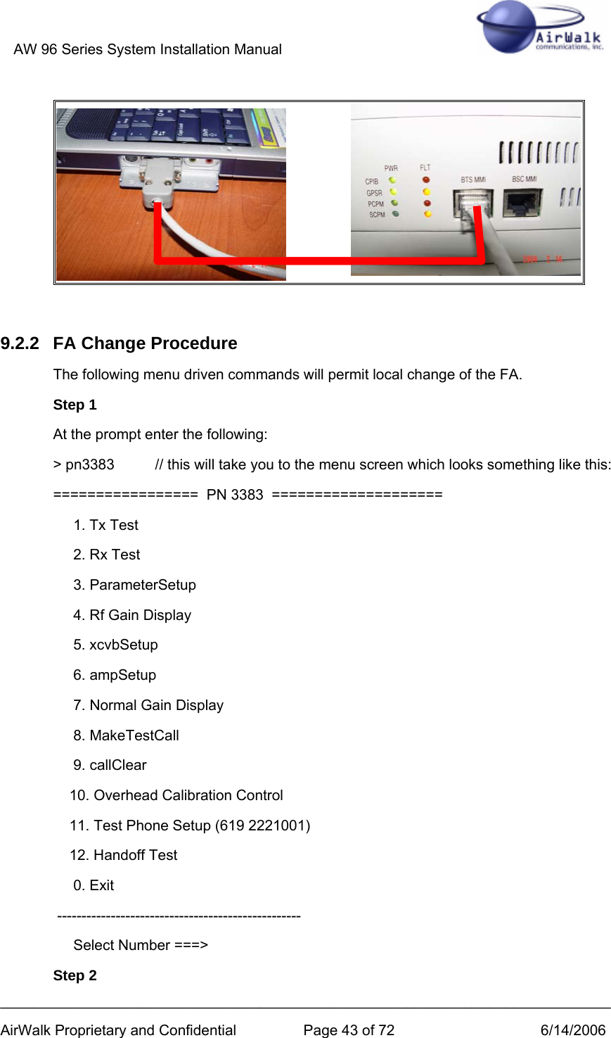
![AW 96 Series System Installation Manual ___________________________________________________________________________ AirWalk Proprietary and Confidential Page 16 of 72 6/14/2006 4.3 Hardware Configuration The IP-BS is a unique modular and stackable combination BSC and BTS platform that is differentiated from other systems. Other systems have separate BTS and BSC platforms which adds to cost and complexity. The AirWalk RAN has a structure that combines and arranges the BSC interface with one 1FA/3Sector BTS in a single package. The main components are (depending on specific model): • AW-96 (Main Unit) o CDPB (Common Digital Processing Board), consisting of: CPIB (Channel Processor and IF Interface Board) PCPM (Primary Call Processor Module) GPSR (Global Positioning System Receiver) o XCVB (RF Transceiver Board) o PSA (Power Supply Assembly) • RU (Remote RF Unit) [3 Sector RU] o HPAU (High Power Amplifier Unit) o AFEU (Antenna Front End Unit) o FANU (Fan Unit) o RPSU (Remote RF Power Supply Unit) [Separate assembly] • Integral Omni RU (Remote RF Unit) o Unified HPAU, AFEU, RPSU in single unit • Optional Cabinet Mounting o Some units may be mounted in an optional cabinet 4.3.1 Physical Description • Main Unit o Dimension: Max. 482mm(W) x 457mm(D) x 178mm(H) o 19” EIA Rack x 4 Rack Units o Weight: 18 kg (3 Sector); 15 kg (Omni) • Sector RU [3 Sector RU] (less power supply) o Dimension: Max. 482mm(W) x 362mm(D) x 355mm(H) o 19” EIA Rack x 8 Rack Units o Weight: 39 kg • Sector RU RPSU (AC Power Supply) o Dimension: Max. 482mm(W) x 446mm(D) x 89mm(H) o 19” EIA Rack x 2 Rack Units o Weight: 9 kg • Integrated Omni RU o Dimension: Max. 482mm(W) x 410mm(D) x 178mm(H) o 19” EIA Rack x 4 Rack Units o Weight: 22 kg • Optional Self-Contained Mounting Cabinet (including casters) o Dimension: Max. 546mm(W) x 610mm(D) x 876mm(H) o 19” EIA Rack x 16 Rack Units mounting space o Refer to Optional Cabinet Installation Manual](https://usermanual.wiki/AirWalk-Communications/AW96R19AB7/User-Guide-675039-Page-16.png)
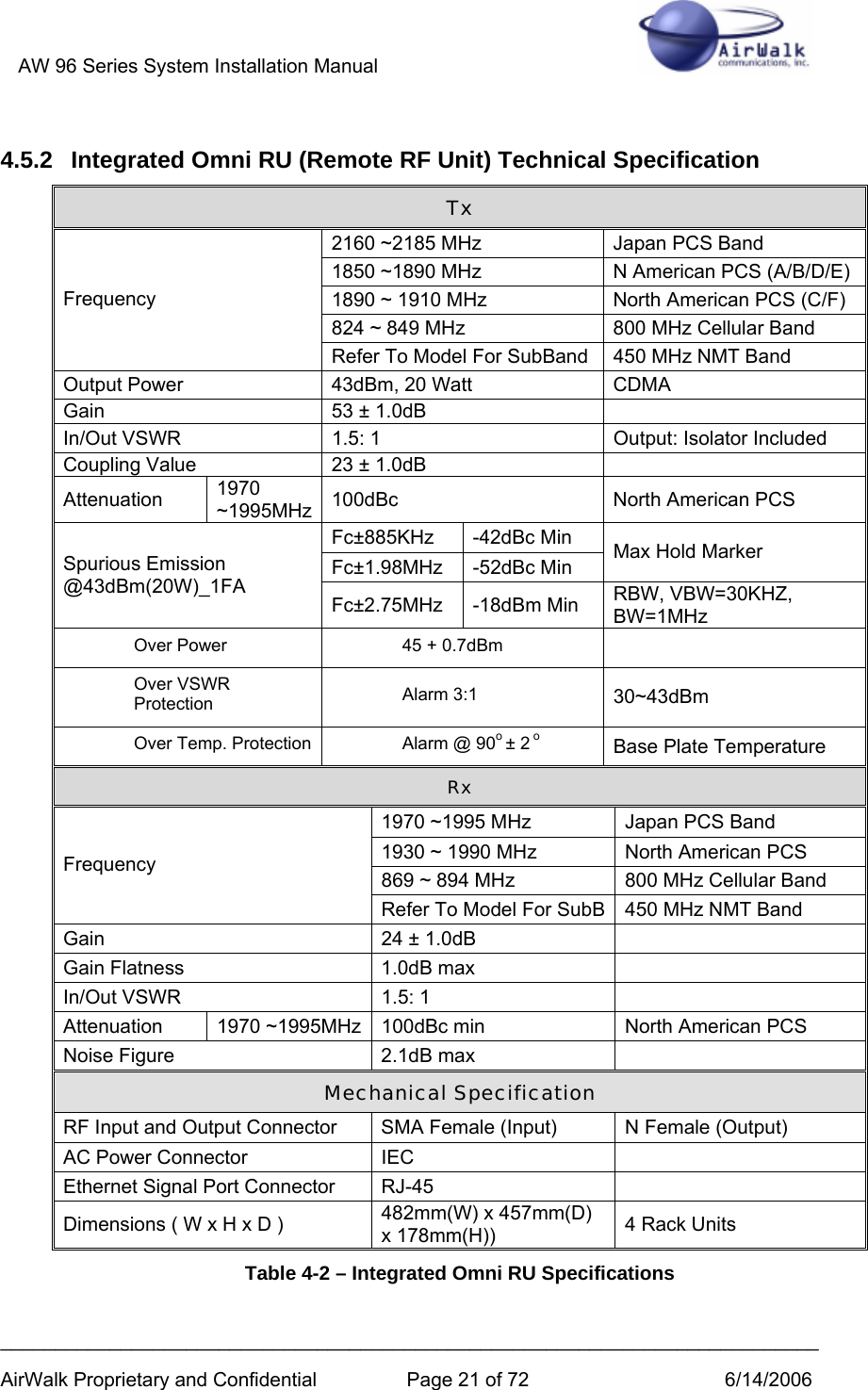
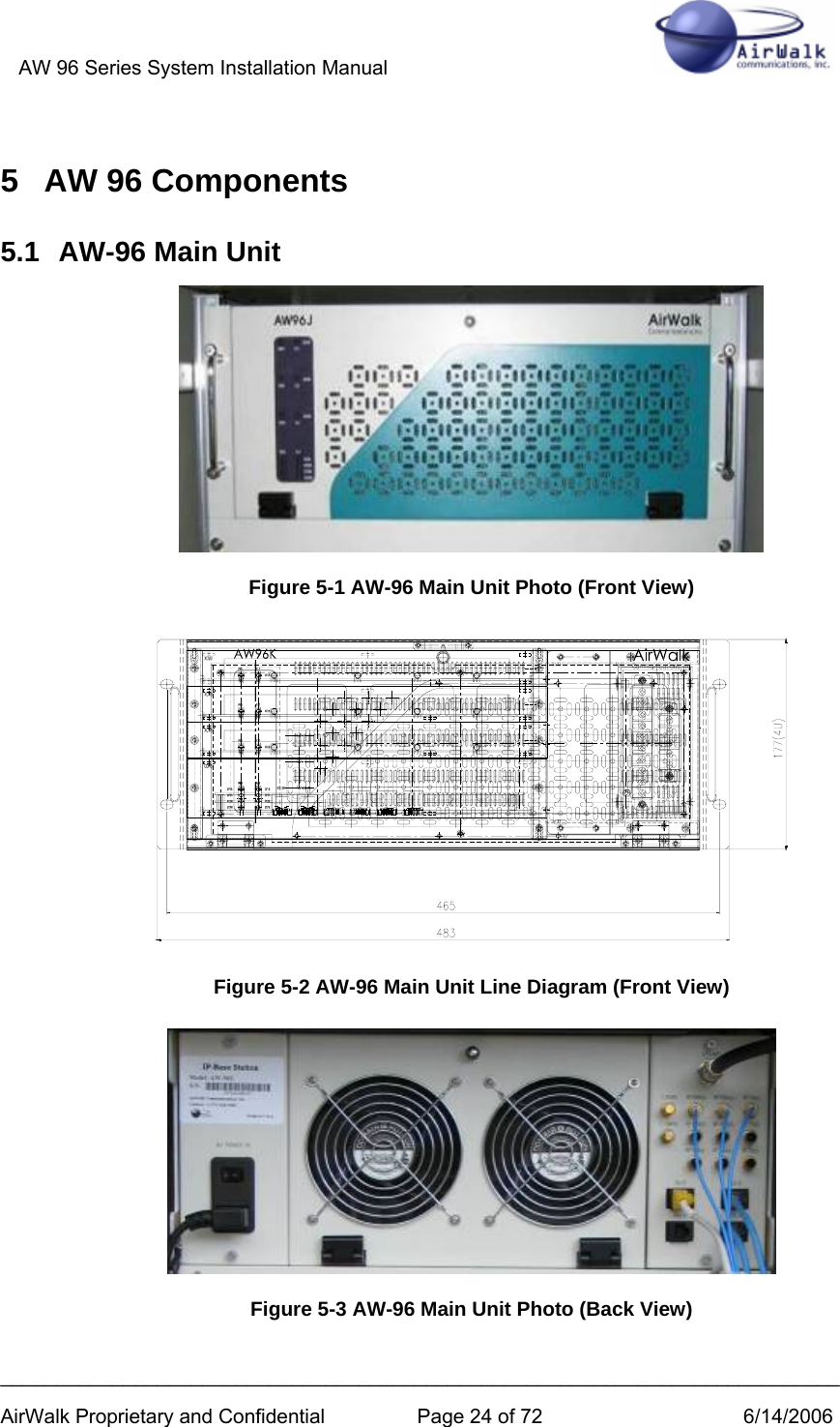
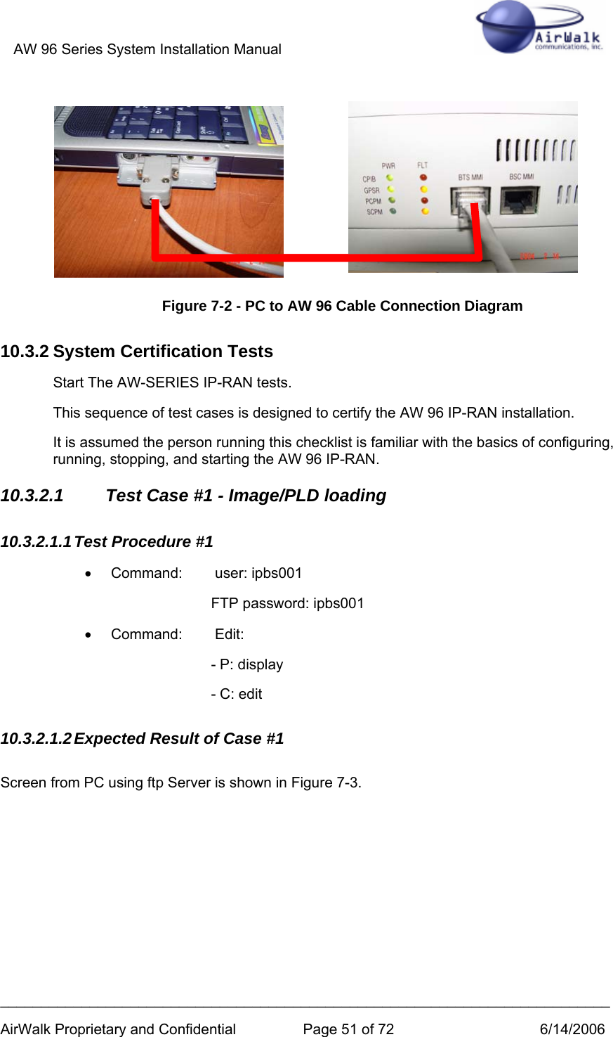
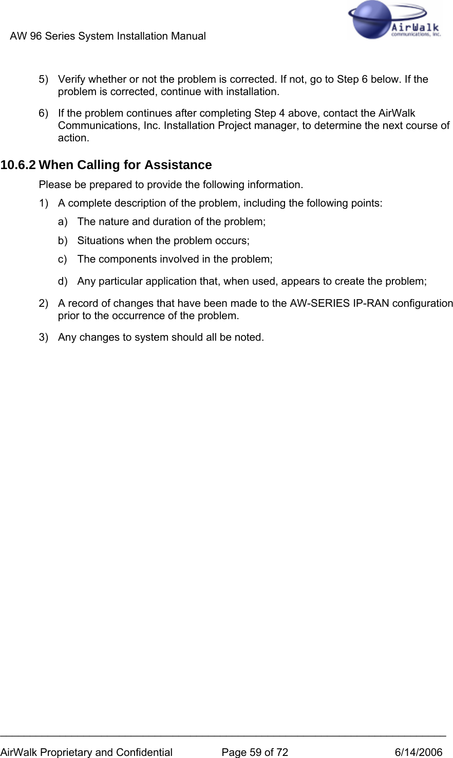
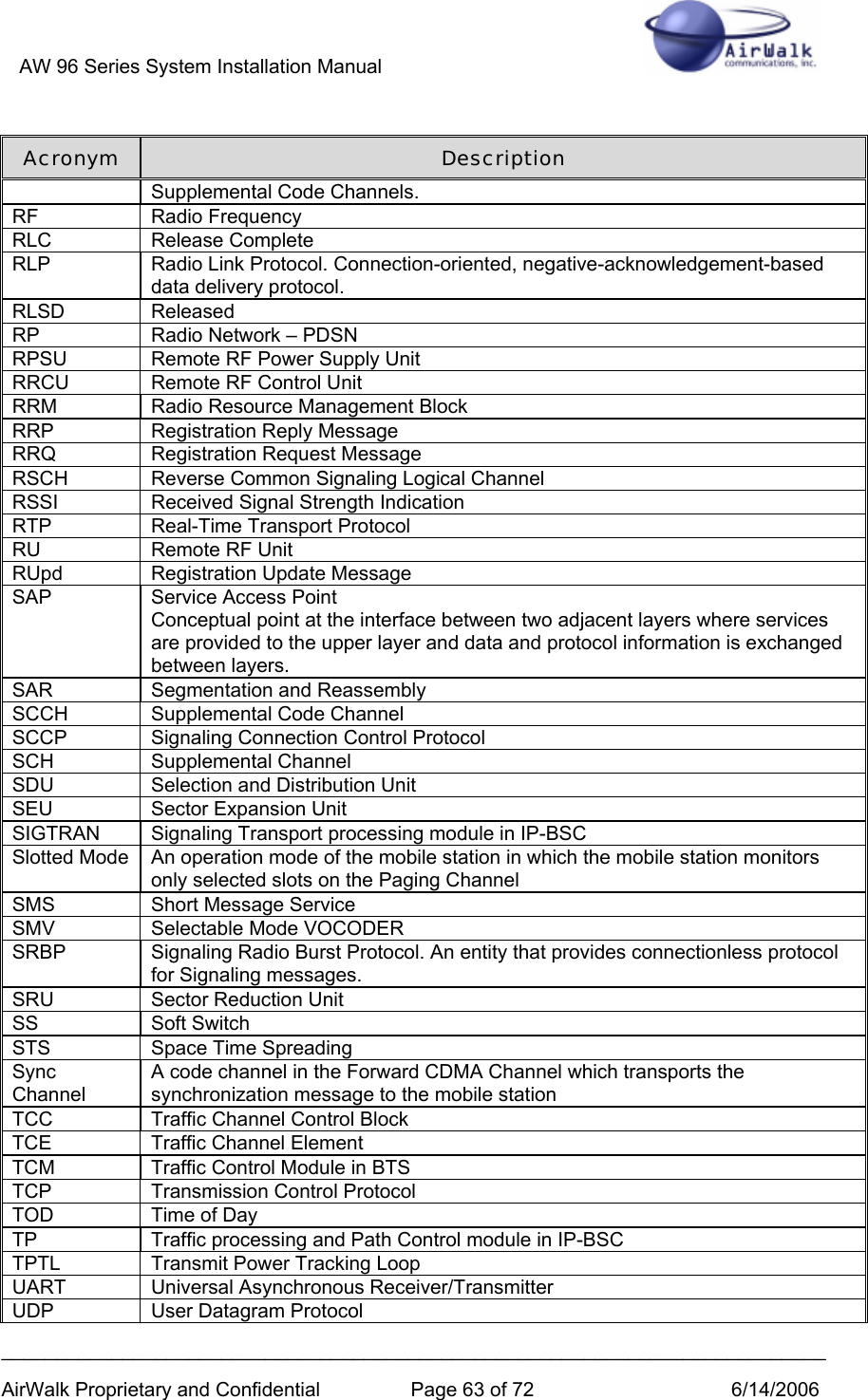
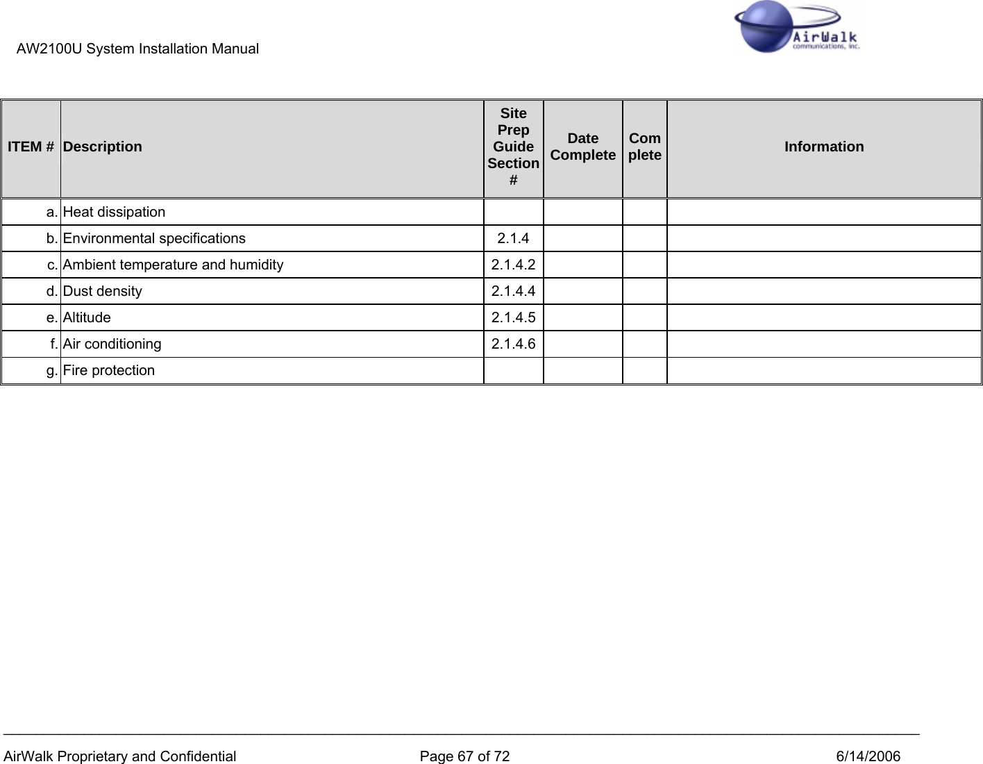
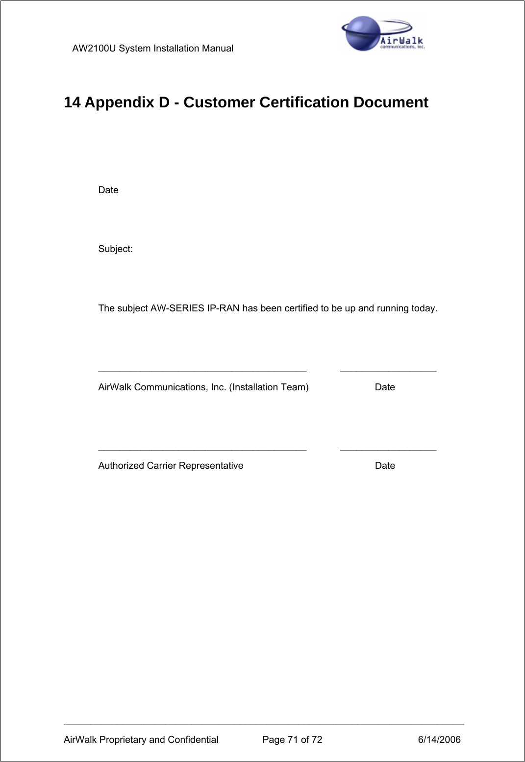
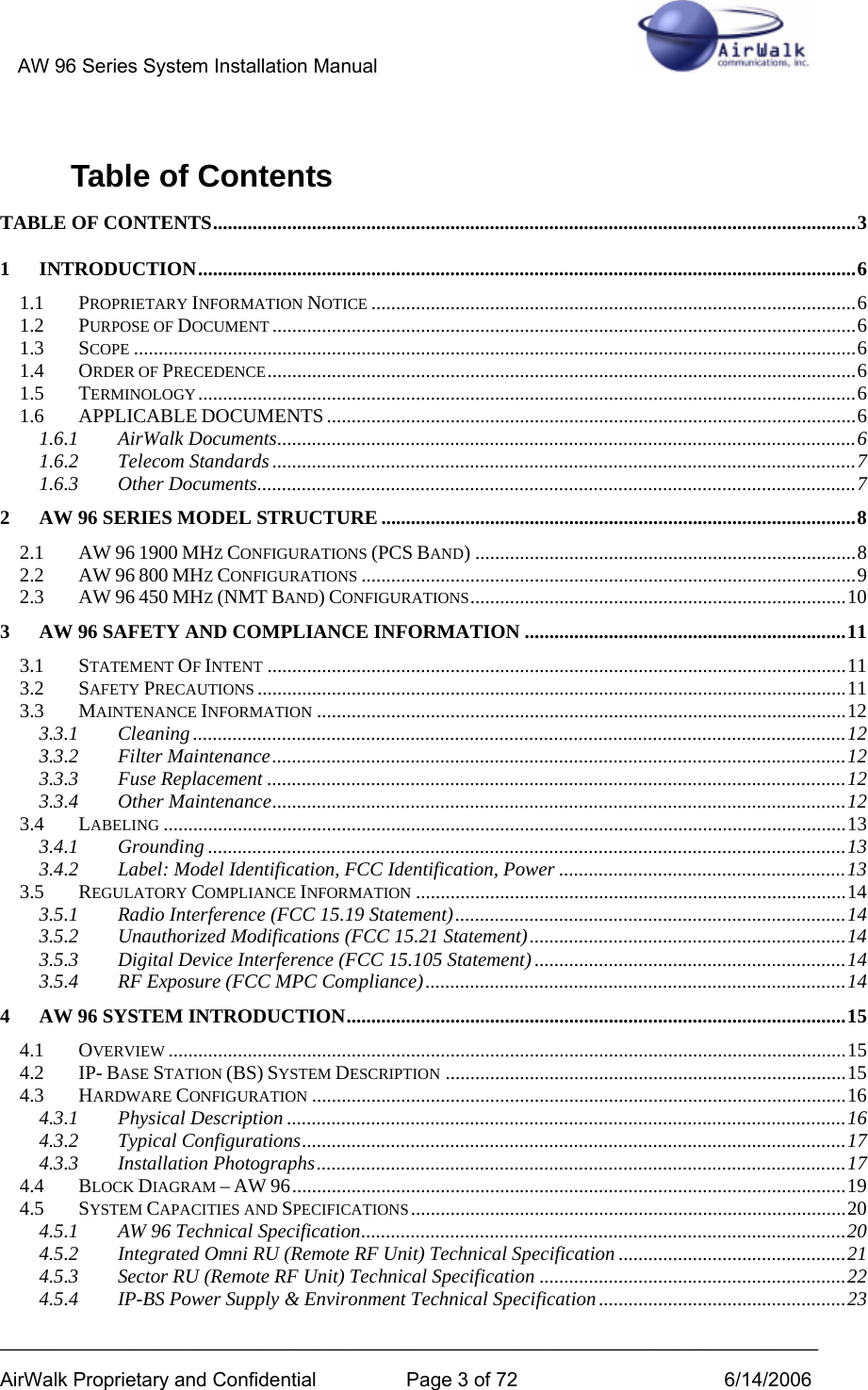
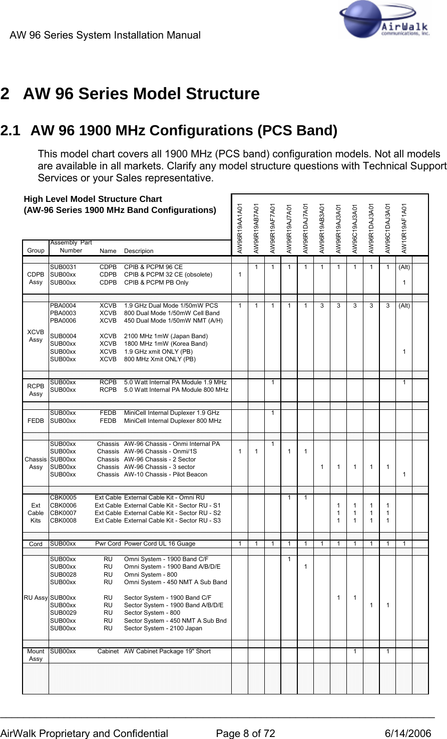
![AW 96 Series System Installation Manual ___________________________________________________________________________ AirWalk Proprietary and Confidential Page 25 of 72 6/14/2006 Figure 5-4 AW-96 – Line Diagram (Back View) 5.2 Integral Omni RU (Remote RF Unit) [Omni Configurations] This is the IP-BS (Internet Protocol BTS System) RF interface system. The main functions include a 20W power amplifier, RF filtering for Tx and Rx paths, a duplexer function for to allow connection to an antenna system, and a power supply. All components are packaged in a unified 4 rack unit package. Figure 5-5 Integrated Omni RF Unit Photo (Front View) Figure 5-6 Integrated Omni RU - Line Diagram (Front View)](https://usermanual.wiki/AirWalk-Communications/AW96R19AB7/User-Guide-675039-Page-25.png)
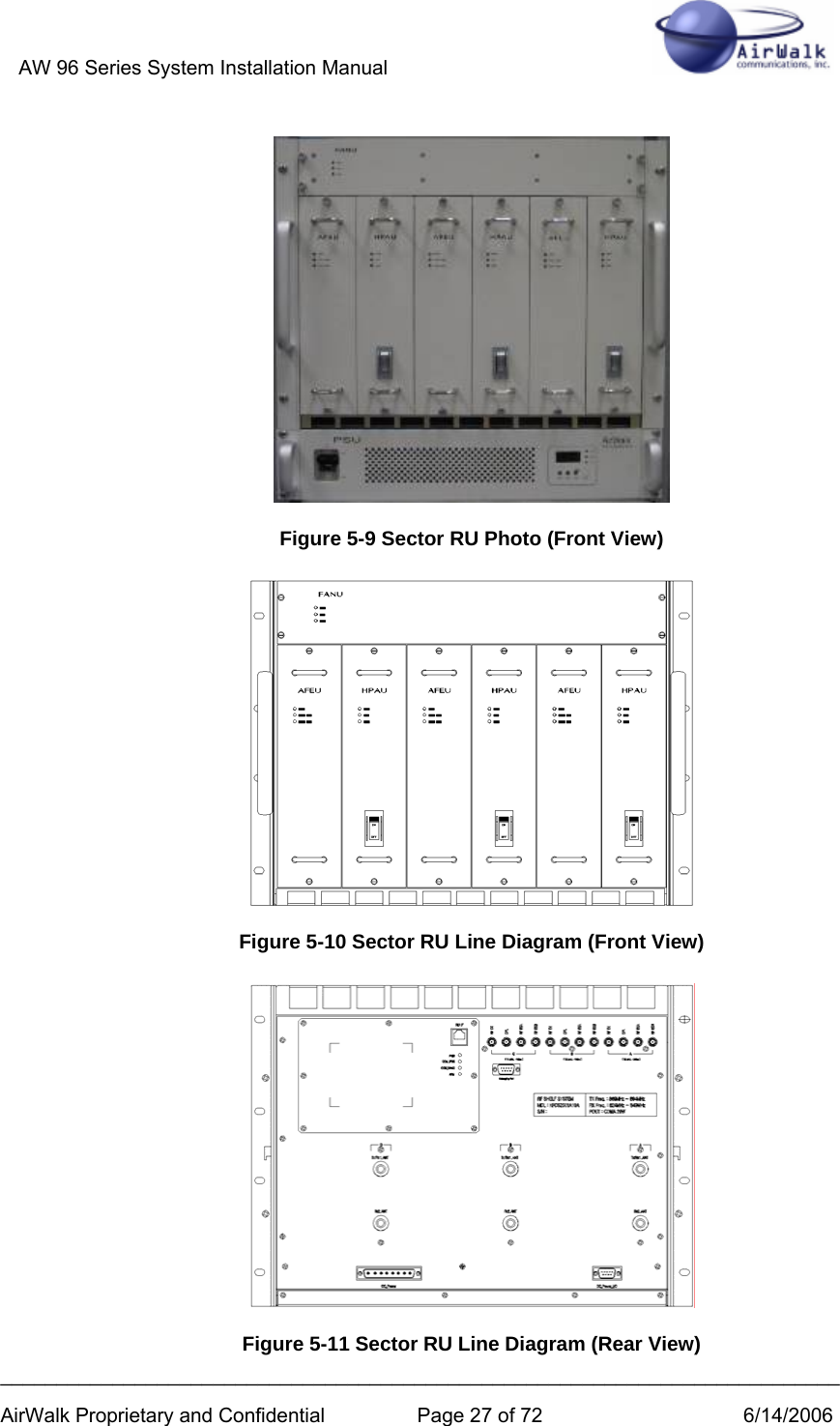
![AW 96 Series System Installation Manual ___________________________________________________________________________ AirWalk Proprietary and Confidential Page 26 of 72 6/14/2006 Figure 5-7 Integrated Omni RU (RF Unit) Photo (Rear View) RF RX_A OUTRJ- 4 5RX_A TPTX/ RX_A ANTTX_TPRF TX INRF RX_B OUTRX_B ANTRX_B TP Figure 5-8 Integrated Omni RU (RF Unit) - Line Diagram (Back View) 5.3 Sector RU (Remote RF Unit) [Sector Configurations] This is the IP-BS (Internet Protocol BTS System) sector RF Shelf. The main functions include a 20W power amplifier for each sector, RF filtering for Tx and Rx paths, a duplexer function for to allow connection to an antenna system, and a power supply. The Sector RU system consists of a common chassis in which the following modules are installed: • HPAU (High Power Amplifier Unit): 20 Watt power amplifier, one per sector • AFEU (Antenna Front End Unit): Includes duplexer and LNA functions, 1/sector • FANU (Fan Unit): Includes fans assemblies for HPAU cooling • PSU (Power Supply Unit): A separate AC power supply for the RU system](https://usermanual.wiki/AirWalk-Communications/AW96R19AB7/User-Guide-675039-Page-26.png)
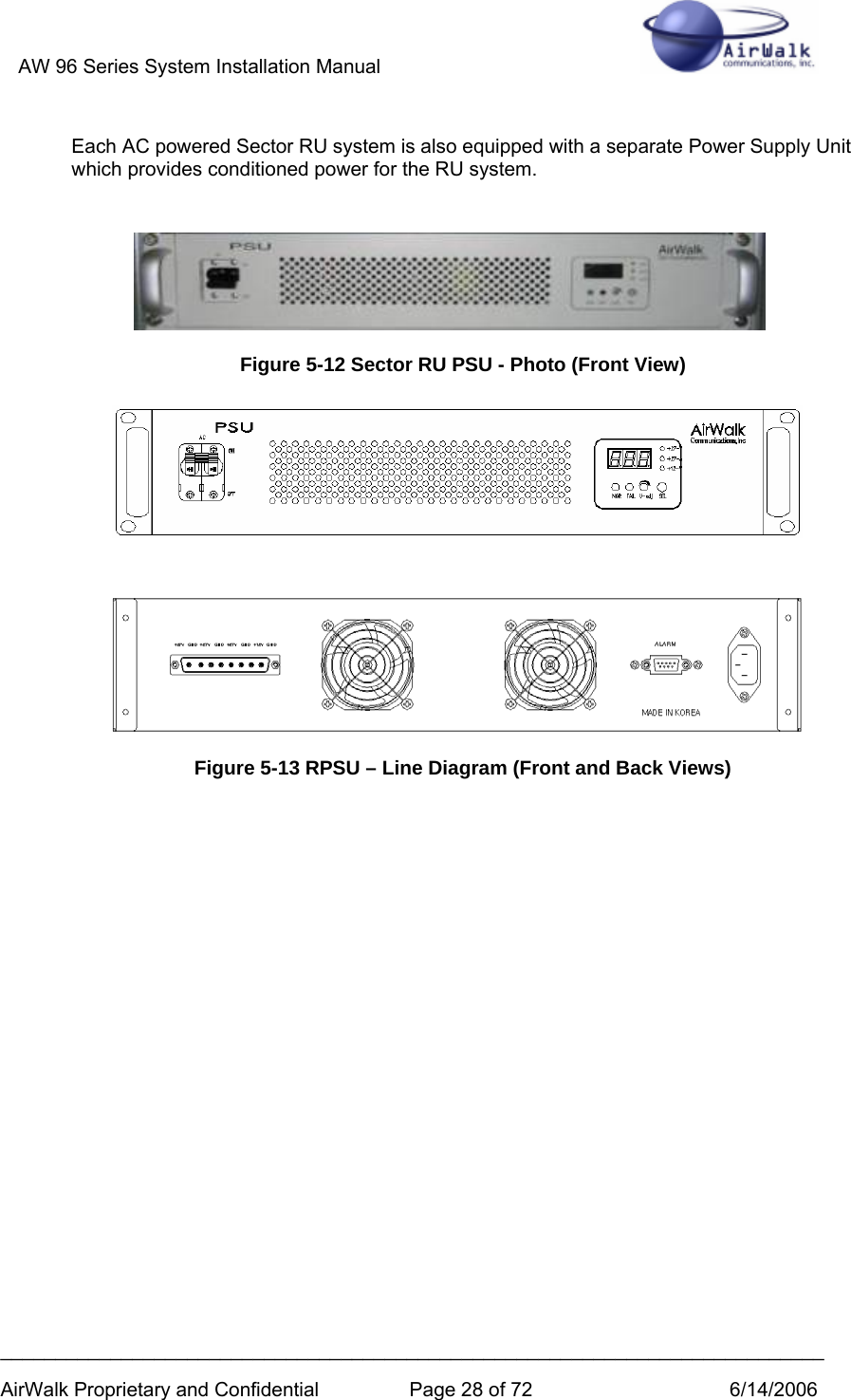
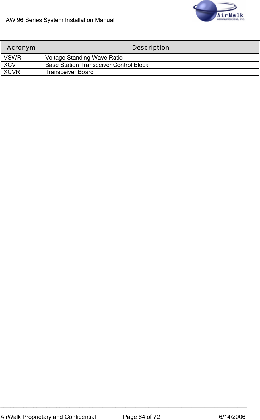
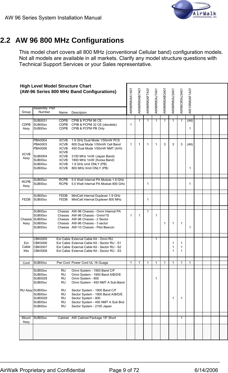
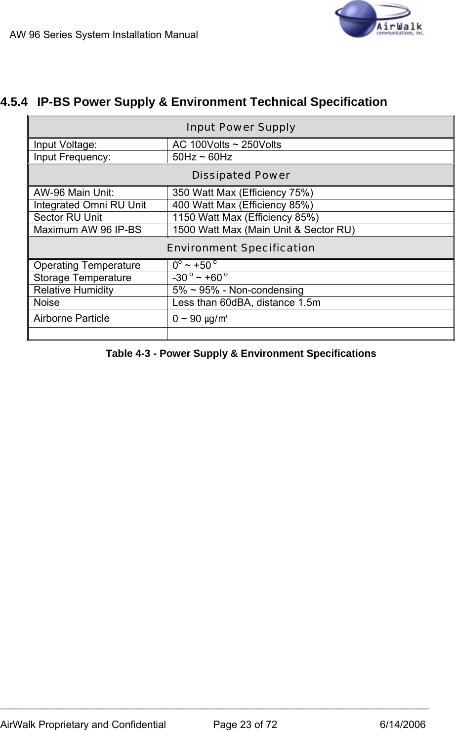
![AW 96 Series System Installation Manual ___________________________________________________________________________ AirWalk Proprietary and Confidential Page 31 of 72 6/14/2006 5.4.2 Sector RU Power Supply Unit (PSU) [AC powered models only] The RU PSU (Power Supply Unit) is equipped with both indicators and a small numeric display. The indicator and display functions relate only to power supply operation for the RU and are described in the following pictures and tables. Note that only AC powered models are equipped with the PSU module. PSU NOR FAIL V-adj SEL +27 -V +27 - A +12 -V Figure 5-6 - RPSU Panel Diagram Figure 5-7 RPSU Panel Photo Name Color On Off Note 1 NOR Green Normal Abnormal RPSU power normal operation indicator 2 FAIL RED Fail Normal RPSU power fail indicator 3 +27-V Green Select Non-Select +27V Voltage select by SEL push switch 4 +27-A Green Select Non-Select +27V Current select by SEL push switch 5 +12-V Green Select Non-Select +12V Voltage select by SEL push switch Table 5-1 - RPSU Indicator Codes](https://usermanual.wiki/AirWalk-Communications/AW96R19AB7/User-Guide-675039-Page-31.png)
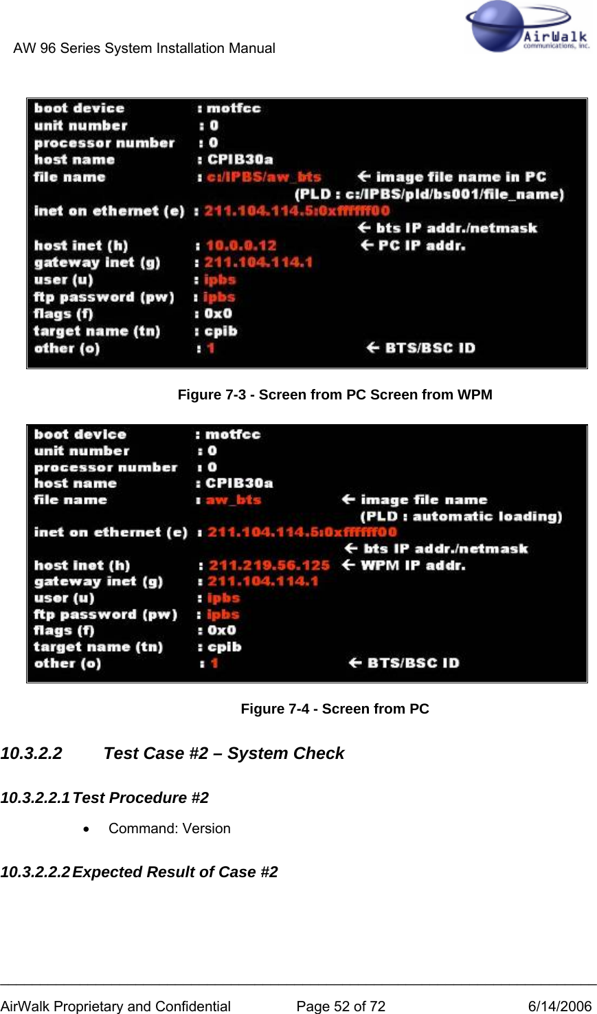
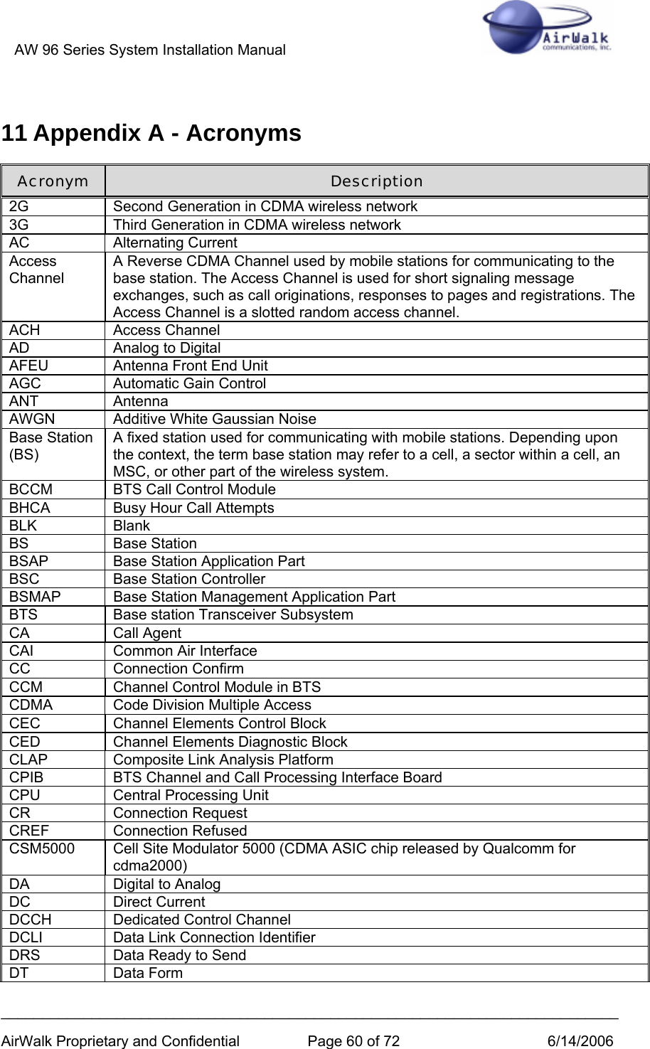
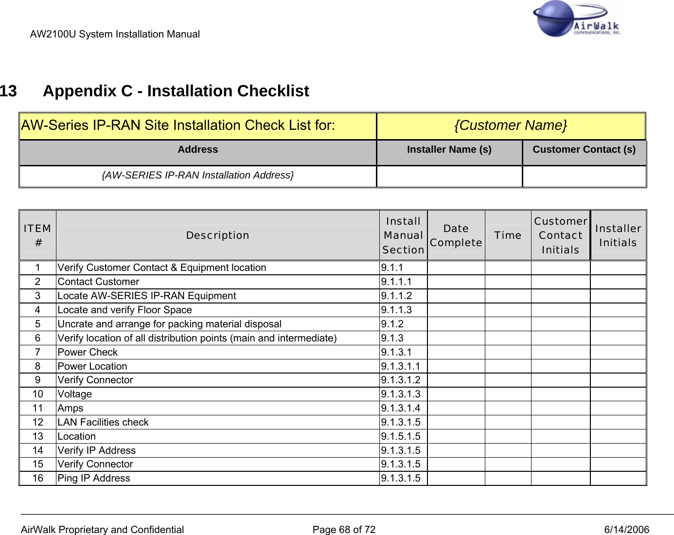
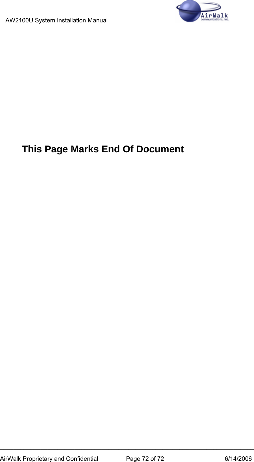
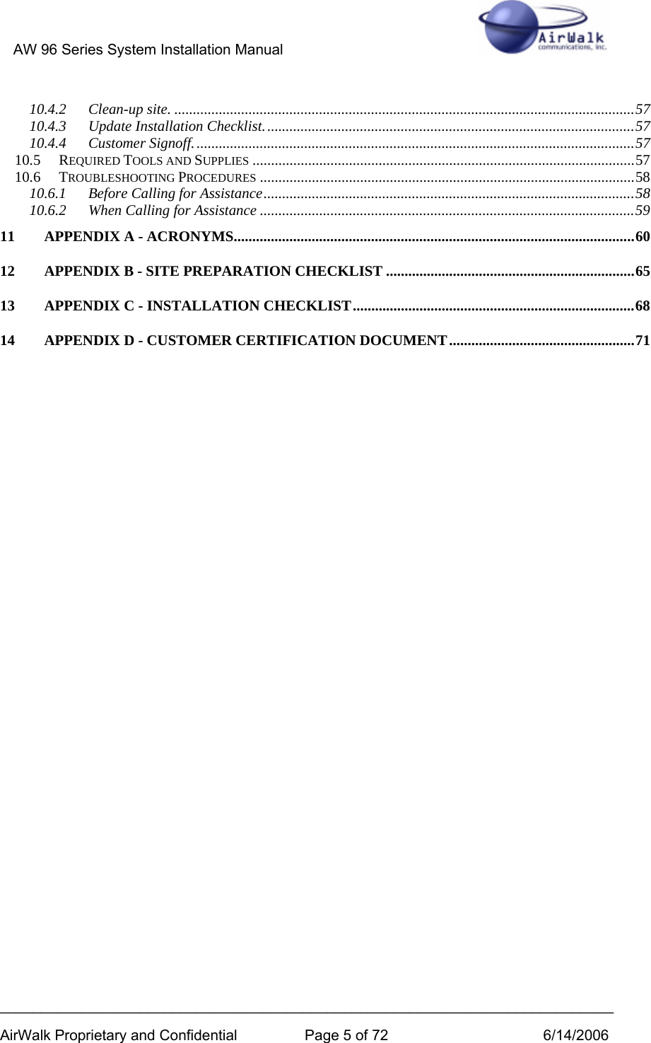
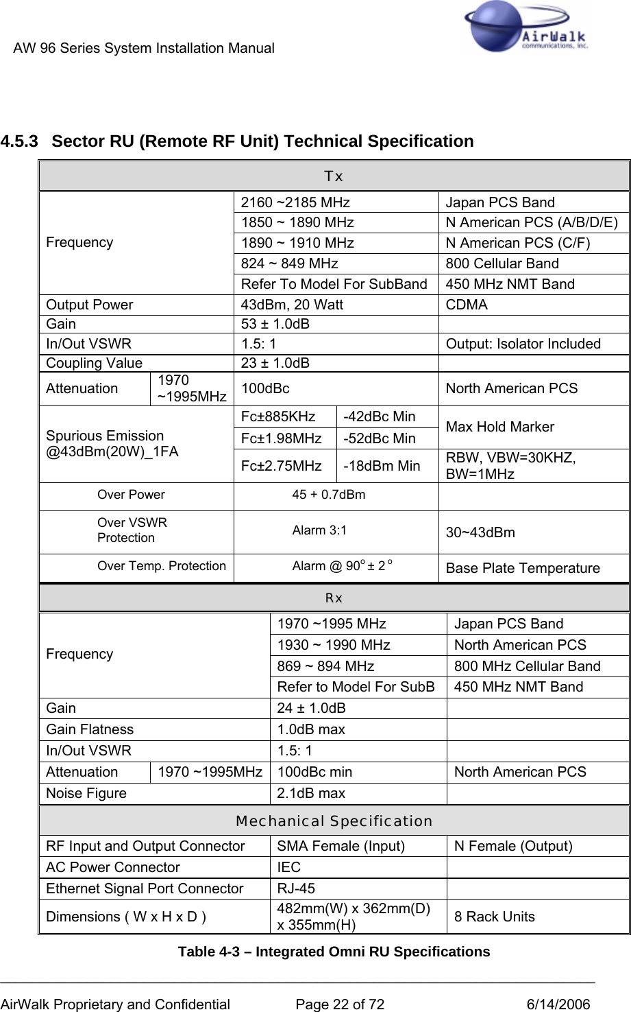
![AW 96 Series System Installation Manual ___________________________________________________________________________ AirWalk Proprietary and Confidential Page 44 of 72 6/14/2006 Enter the following: Select number => 5 // it will take you to the below menu screen. ================= Xcvb Setup ==================== 1. Change Ch 2. Tx On 3. Tx Off 4. Rx_Main_AGC ON 5. Rx_Main_AGC OFF 6. Rx_Sub_AGC ON 7. Rx_Sub_AGC OFF 8. Set RxMain ATT 9. Set RxSub ATT 10. Set Tx Att 11. Xcvb Status 12. showXcvrAttGain 0. Exit -------------------------------------------------- Select Input Number =====> Step 3 Enter the following: Select Input Number => 1 // choosing 1 will take you to the below menu. ALPHA : xcvrChangeCh Num [001 ~ 1500] [1175] [/0:Exit]==> Step 4 From the above menu, type the new channel desired (CDMA channels from 1 to 1500) and 0 to exit. Note that for 3 sector base stations Step 3 must be repeated for each sector (alpha, beta, and gamma). Note that only standard CDMA channel numbers within the designated band capability of the radio will be accepted by the base station.](https://usermanual.wiki/AirWalk-Communications/AW96R19AB7/User-Guide-675039-Page-44.png)