AirWalk Communications AW96R19AB7 AW96R19AB7A01 Pico MiniCell User Manual
AirWalk Communications, Inc. AW96R19AB7A01 Pico MiniCell Users Manual
Users Manual

___________________________________________________________________________
AirWalk Proprietary and Confidential Page 1 of 72 6/14/2006
AW 96 Series Installation & Maintenance Manual
Version # 1.5
June 2006
Prepared By
AirWalk Communications, Inc.
1830 North Greenville Ave
Richardson, TX, 75081
Phone: (972) 638-9400
Fax: (972) 638-9401
www.airwalkcom.com
FOR USE BY TRAINED TECHNICIANS ONLY
AW 96 Series System Installation Manual
___________________________________________________________________________
AirWalk Proprietary and Confidential Page 2 of 72 6/14/2006
Revision History
Version Date Person Description
0.1 03/01/2004 WC/JMH Draft Document (source AW 2100)
0.2 8/17/2004 CMO Corrected drawings/specifications
0.3 8/17/2004 CMO Revised for ETL compliance, Labeling
1.0 8/20/2004 CMO Released
1.1 1/5/2005 CMO Updated Omni Model Chart
1.2 3/15/2005 CMO Added Sector RU
1.3 11/4/2005 CMO Revised Sector RU diagrams
1.4 4/30/2006 CMO Added MicoCell/PicoCell Cabling section
1.5 6/14/2006 CMO Added regulatory compliance information
Revision Numbering Key
0.x Work in Progress
1.0 Initial Document Approval
1.x Revisions Following Initial Document Approval
2.0 Revisions Approval

AW 96 Series System Installation Manual
___________________________________________________________________________
AirWalk Proprietary and Confidential Page 3 of 72 6/14/2006
Table of Contents
TABLE OF CONTENTS..................................................................................................................................3
1 INTRODUCTION.....................................................................................................................................6
1.1 PROPRIETARY INFORMATION NOTICE ..................................................................................................6
1.2 PURPOSE OF DOCUMENT ......................................................................................................................6
1.3 SCOPE ..................................................................................................................................................6
1.4 ORDER OF PRECEDENCE.......................................................................................................................6
1.5 TERMINOLOGY.....................................................................................................................................6
1.6 APPLICABLE DOCUMENTS ...........................................................................................................6
1.6.1 AirWalk Documents.....................................................................................................................6
1.6.2 Telecom Standards......................................................................................................................7
1.6.3 Other Documents.........................................................................................................................7
2 AW 96 SERIES MODEL STRUCTURE ................................................................................................8
2.1 AW 96 1900 MHZ CONFIGURATIONS (PCS BAND) .............................................................................8
2.2 AW 96 800 MHZ CONFIGURATIONS ....................................................................................................9
2.3 AW 96 450 MHZ (NMT BAND) CONFIGURATIONS............................................................................10
3 AW 96 SAFETY AND COMPLIANCE INFORMATION .................................................................11
3.1 STATEMENT OF INTENT .....................................................................................................................11
3.2 SAFETY PRECAUTIONS .......................................................................................................................11
3.3 MAINTENANCE INFORMATION ...........................................................................................................12
3.3.1 Cleaning ....................................................................................................................................12
3.3.2 Filter Maintenance....................................................................................................................12
3.3.3 Fuse Replacement .....................................................................................................................12
3.3.4 Other Maintenance....................................................................................................................12
3.4 LABELING ..........................................................................................................................................13
3.4.1 Grounding .................................................................................................................................13
3.4.2 Label: Model Identification, FCC Identification, Power ..........................................................13
3.5 REGULATORY COMPLIANCE INFORMATION .......................................................................................14
3.5.1 Radio Interference (FCC 15.19 Statement)...............................................................................14
3.5.2 Unauthorized Modifications (FCC 15.21 Statement)................................................................14
3.5.3 Digital Device Interference (FCC 15.105 Statement)...............................................................14
3.5.4 RF Exposure (FCC MPC Compliance).....................................................................................14
4 AW 96 SYSTEM INTRODUCTION.....................................................................................................15
4.1 OVERVIEW .........................................................................................................................................15
4.2 IP- BASE STATION (BS) SYSTEM DESCRIPTION .................................................................................15
4.3 HARDWARE CONFIGURATION ............................................................................................................16
4.3.1 Physical Description .................................................................................................................16
4.3.2 Typical Configurations..............................................................................................................17
4.3.3 Installation Photographs...........................................................................................................17
4.4 BLOCK DIAGRAM – AW 96................................................................................................................19
4.5 SYSTEM CAPACITIES AND SPECIFICATIONS........................................................................................20
4.5.1 AW 96 Technical Specification..................................................................................................20
4.5.2 Integrated Omni RU (Remote RF Unit) Technical Specification ..............................................21
4.5.3 Sector RU (Remote RF Unit) Technical Specification ..............................................................22
4.5.4 IP-BS Power Supply & Environment Technical Specification ..................................................23

AW 96 Series System Installation Manual
___________________________________________________________________________
AirWalk Proprietary and Confidential Page 4 of 72 6/14/2006
5 AW 96 COMPONENTS .........................................................................................................................24
5.1 AW-96 MAIN UNIT............................................................................................................................24
5.2 INTEGRAL OMNI RU (REMOTE RF UNIT) [OMNI CONFIGURATIONS].................................................25
5.3 SECTOR RU (REMOTE RF UNIT) [SECTOR CONFIGURATIONS]...........................................................26
5.4 COMPONENT LED CONFIGURATION ..................................................................................................29
5.4.1 CDPB (Common Digital Processing Block)..............................................................................29
XCVB.........................................................................................................................................................30
5.4.2 Sector RU Power Supply Unit (PSU) [AC powered models only] ............................................31
6 AW 96 INTEGRATED OMNI RU INTERFACE CABLING ............................................................32
6.1 RF CABLING – INTEGRATED RU OMNI CONFIGURATION...................................................................32
6.2 ELECTRIC POWER CABLE WIRING......................................................................................................33
6.3 ETHERNET CABLE WIRING.................................................................................................................34
6.4 GPS ANTENNA CABLE WIRING..........................................................................................................34
6.5 PHOTOGRAPH OF TYPICAL CABLE WIRING........................................................................................35
7 AW 96 SECTOR RU INTERFACE CABLING...................................................................................36
7.1 RF CABLING – SECTOR RU CONFIGURATION (3 SECTOR)..................................................................36
7.2 RU POWER SUPPLY INTERCONNECT WIRING .....................................................................................37
7.3 ETHERNET/SERIAL CABLE WIRING ....................................................................................................37
7.4 ELECTRIC POWER CABLE WIRING......................................................................................................38
7.5 GPS ANTENNA CABLE WIRING..........................................................................................................39
7.6 PHOTOGRAPH OF TYPICAL CABLE WIRING........................................................................................40
8 AW 96 LOW POWER (PICOCELL/MICROCELL) CABLING ......................................................41
9 FREQUENCY SETTING PROCEDURES ..........................................................................................42
9.1 BSM MANAGEMENT..........................................................................................................................42
9.2 LOCAL FA SETTING ...........................................................................................................................42
9.2.1 MMI Connection .......................................................................................................................42
9.2.2 FA Change Procedure...............................................................................................................43
10 INSTALLATION PROCEDURES....................................................................................................46
10.1 INSTALLATION VERIFICATION............................................................................................................46
10.1.1 Verify Customer Contact & Equipment location.......................................................................46
10.1.2 Uncrate and arrange for packing material disposal.................................................................47
10.1.3 Verify location of all Facility distribution points (main and intermediate)..............................47
10.2 AW-SERIES IP-RAN INSTALL PROCEDURES ...................................................................................48
10.2.1 Install AW-SERIES IP-RAN Cabinet.........................................................................................48
10.2.2 Verify All Internal System Connections.....................................................................................48
10.2.3 External System Connections....................................................................................................49
10.2.4 Connect Power to Cabinet ........................................................................................................49
10.2.5 Connect Communications Facilities..........................................................................................49
10.2.6 Power-up procedure..................................................................................................................50
10.3 SYSTEM TEST.....................................................................................................................................50
10.3.1 PC to AW 96 cable ....................................................................................................................50
10.3.2 System Certification Tests .........................................................................................................51
10.3.3 Operation Tests .........................................................................................................................56
10.3.4 Operator Specific Tests .............................................................................................................57
10.4 SITE CLEAN UP AND CUSTOMER SIGNOFF ..........................................................................................57
10.4.1 Dispose of all packing material.................................................................................................57

AW 96 Series System Installation Manual
___________________________________________________________________________
AirWalk Proprietary and Confidential Page 5 of 72 6/14/2006
10.4.2 Clean-up site. ............................................................................................................................57
10.4.3 Update Installation Checklist....................................................................................................57
10.4.4 Customer Signoff.......................................................................................................................57
10.5 REQUIRED TOOLS AND SUPPLIES .......................................................................................................57
10.6 TROUBLESHOOTING PROCEDURES .....................................................................................................58
10.6.1 Before Calling for Assistance....................................................................................................58
10.6.2 When Calling for Assistance .....................................................................................................59
11 APPENDIX A - ACRONYMS............................................................................................................60
12 APPENDIX B - SITE PREPARATION CHECKLIST ...................................................................65
13 APPENDIX C - INSTALLATION CHECKLIST............................................................................68
14 APPENDIX D - CUSTOMER CERTIFICATION DOCUMENT..................................................71

AW 96 Series System Installation Manual
___________________________________________________________________________
AirWalk Proprietary and Confidential Page 6 of 72 6/14/2006
1 INTRODUCTION
1.1 Proprietary Information Notice
THIS DOCUMENT IS THE PROPERTY OF AIRWALK COMMUNICATIONS, INC. THE
RECIPIENT MAY USE IT ONLY FOR THE PURPOSE FOR WHICH IT WAS
TRANSMITTED AND WILL BE RETURNED UPON REQUEST OR WHEN NO LONGER
NEEDED BY RECIPIENT. IT MAY NOT BE COPIED OR COMMUNICATED WITHOUT
THE WRITTEN CONSENT OF AIRWALK COMMUNICATIONS, INC.
1.2 Purpose of Document
The purpose of this document is to define the Installation, Maintenance and Safety
Compliance of AirWalk Communication’s, Inc. unique CDMA Radio Access Network
(RAN) system. The AirWalk RAN is a market ready, standards compliant, high channel
capacity, cost effective, modular and expandable wireless radio access network system.
Designed specifically for CDMA2000 networks, the Base Station Transceiver (BTS) and
Base Station Controller (BSC) are integrated into a single compact platform.
The target market and applications are in-building areas, corporations, corporate
campuses, enterprises, university campuses, large industrial plants, stadiums, airports,
shopping malls, blind spots, hot spots, rural areas, neighborhoods, and highways.
1.3 Scope
The scope of this document covers the description, environmental specifications,
equipment location, cabling, system installation and maintenance of the AirWalk RAN.
Specific models covered are identified in the section entitled “Model Information”.
1.4 Order of Precedence
This System Installation Manual will take precedence over any previous AirWalk System
Installation Manual or Document.
1.5 Terminology
See the section entitled: Appendix A - Acronyms
1.6 APPLICABLE DOCUMENTS
The following documents are applicable to the extent specified in this System Installation
Manual.
1.6.1 AirWalk Documents
• IP- Base Station (BS) System Description.
• IP- Base Station (BS) CPIB Block Diagram.
• IP- Base Station (BS) GPSR Block Diagram.
• IP- Base Station (BS) PCPM Block Diagram.
• IP- Base Station (BS) XCVB Block Diagram.
• AirWalk System Specification-11-13-2003-v1.0.

AW 96 Series System Installation Manual
___________________________________________________________________________
AirWalk Proprietary and Confidential Page 7 of 72 6/14/2006
• System User Manual_022404.
• System Installation Manual_030104.
1.6.2 Telecom Standards
• TIA/EIA/IS-2000 Series Revision: C - Introduction to CDMA2000 Spread Spectrum
Systems, 05/00/02
• Personal Station – Base Station Compatibility Requirements for1.8 to 2.0 GHz CDMA
PCS.
• TIA/EIA-664 - Wireless Features Description, 12/00/00
• TIA/EIA Interim Standard 95 Revision A - Mobile Station –Base Station Compatibility
Standard for Dual-Mode Wideband Spread Spectrum Cellular Systems, May 1995
• TIA/EIA-95-B - Mobile Station-Base Station Compatibility Standard for Dual-Mode
Spread Spectrum Systems, October 31, 1998
• MSC to BS Interface Inter-Operability Specification (IOS) IOS-4.2
• IMT-2000 Specification, (indoor wireless propagation)
1.6.3 Other Documents
None Identified
AW 96 Series System Installation Manual
___________________________________________________________________________
AirWalk Proprietary and Confidential Page 8 of 72 6/14/2006
2 AW 96 Series Model Structure
2.1 AW 96 1900 MHz Configurations (PCS Band)
This model chart covers all 1900 MHz (PCS band) configuration models. Not all models
are available in all markets. Clarify any model structure questions with Technical Support
Services or your Sales representative.
Group
Assembly Part
Number Name Descripion
SUB0031 CDPB CPIB & PCPM 96 CE 1 1 1 1 1 1 1 1 1 (Alt)
SUB00xx CDPB CPIB & PCPM 32 CE (obsolete) 1
SUB00xx CDPB CPIB & PCPM PB Only 1
PBA0004 XCVB 1.9 GHz Dual Mode 1/50mW PCS 1 1 1 1 1 3 3 3 3 3 (Alt)
PBA0003 XCVB 800 Dual Mode 1/50mW Cell Band
PBA0006 XCVB 450 Dual Mode 1/50mW NMT (A/H)
SUB0004 XCVB 2100 MHz 1mW (Japan Band)
SUB00xx XCVB 1800 MHz 1mW (Korea Band)
SUB00xx XCVB 1.9 GHz xmit ONLY (PB) 1
SUB00xx XCVB 800 MHz Xmit ONLY (PB)
SUB00xx RCPB 5.0 Watt Internal PA Module 1.9 MHz 1 1
SUB00xx RCPB 5.0 Watt Internal PA Module 800 MHz
SUB00xx FEDB MiniCell Internal Duplexer 1.9 GHz 1
SUB00xx FEDB MiniCell Internal Duplexer 800 MHz
SUB00xx Chassis AW-96 Chassis - Onmi Internal PA 1
SUB00xx Chassis AW-96 Chassis - Onmi/1S 1 1 1 1
SUB00xx Chassis AW-96 Chassis - 2 Sector
SUB00xx Chassis AW-96 Chassis - 3 sector 1 1 1 1 1
SUB00xx Chassis AW-10 Chassis - Pilot Beacon 1
CBK0005 Ext Cable External Cable Kit - Omni RU 1 1
CBK0006 Ext Cable External Cable Kit - Sector RU - S1 1 1 1 1
CBK0007 Ext Cable External Cable Kit - Sector RU - S2 1 1 1 1
CBK0008 Ext Cable External Cable Kit - Sector RU - S3 1 1 1 1
Cord SUB00xx Pwr Cord Power Cord UL 16 Guage 1 1 1 1 1 1 1 1 1 1 1
SUB00xx RU Omni System - 1900 Band C/F 1
SUB00xx RU Omni System - 1900 Band A/B/D/E 1
SUB0028 RU Omni System - 800
SUB00xx RU Omni System - 450 NMT A Sub Band
SUB00xx RU Sector System - 1900 Band C/F 1 1
SUB00xx RU Sector System - 1900 Band A/B/D/E 1 1
SUB0029 RU Sector System - 800
SUB00xx RU Sector System - 450 NMT A Sub Bnd
SUB00xx RU Sector System - 2100 Japan
SUB00xx Cabinet AW Cabinet Package 19" Short 1 1
XCVB
Assy
Mount
Assy
RU Assy
CDPB
Assy
AW96R19AA1A01
AW96R19AB7A01
Ext
Cable
Kits
RCPB
Assy
FEDB
Chassis
Assy
High Level Model Structure Chart
(AW-96 Series 1900 MHz Band Configurations)
AW96C1DAJ3A01
AW96R19AJ7A01
AW96R19AB3A01
AW96R19AJ3A01
AW10R19AF1A01
AW96R19AF7A01
AW96R1DAJ7A01
AW96R1DAJ3A01
AW96C19AJ3A01

AW 96 Series System Installation Manual
___________________________________________________________________________
AirWalk Proprietary and Confidential Page 9 of 72 6/14/2006
2.2 AW 96 800 MHz Configurations
This model chart covers all 800 MHz (conventional Cellular band) configuration models.
Not all models are available in all markets. Clarify any model structure questions with
Technical Support Services or your Sales representative.
Group
Assembly Part
Number Name Descripion
SUB0031 CDPB CPIB & PCPM 96 CE 1 1 1 1 1 1 (Alt)
SUB00xx CDPB CPIB & PCPM 32 CE (obsolete) 1
SUB00xx CDPB CPIB & PCPM PB Only 1
PBA0004 XCVB 1.9 GHz Dual Mode 1/50mW PCS
PBA0003 XCVB 800 Dual Mode 1/50mW Cell Band 1 1 1 1 3 3 3 (Alt)
PBA0006 XCVB 450 Dual Mode 1/50mW NMT (A/H)
XCVB
SUB0004 XCVB 2100 MHz 1mW (Japan Band)
SUB00xx XCVB 1800 MHz 1mW (Korea Band)
SUB00xx XCVB 1.9 GHz xmit ONLY (PB)
SUB00xx XCVB 800 MHz Xmit ONLY (PB) 1
SUB00xx RCPB 5.0 Watt Internal PA Module 1.9 GHz
SUB00xx RCPB 5.0 Watt Internal PA Module 800 GHz 1 1
SUB00xx FEDB MiniCell Internal Duplexer 1.9 GHz
SUB00xx FEDB MiniCell Internal Duplexer 800 MHz 1
SUB00xx Chassis AW-96 Chassis - Onmi Internal PA 1
SUB00xx Chassis AW-96 Chassis - Onmi/1S 1 1 1
SUB00xx Chassis AW-96 Chassis - 2 Sector
SUB00xx Chassis AW-96 Chassis - 3 sector 1 1 1
SUB00xx Chassis AW-10 Chassis - Pilot Beacon 1
CBK0005 Ext Cable External Cable Kit - Omni RU 1
CBK0006 Ext Cable External Cable Kit - Sector RU - S1 1 1
CBK0007 Ext Cable External Cable Kit - Sector RU - S2 1 1
CBK0008 Ext Cable External Cable Kit - Sector RU - S3 1 1
Cord SUB00xx Pwr Cord Power Cord UL 16 Guage 1 1 1 1 1 1 1 1
SUB00xx RU Omni System - 1900 Band C/F
SUB00xx RU Omni System - 1900 Band A/B/D/E
SUB0028 RU Omni System - 800 1
SUB00xx RU Omni System - 450 NMT A Sub-Band
SUB00xx RU Sector System - 1900 Band C/F
SUB00xx RU Sector System - 1900 Band A/B/D/E
SUB0029 RU Sector System - 800 1 1
SUB00xx RU Sector System - 450 NMT A Sub Bnd
SUB00xx RU Sector System - 2100 Japan
SUB00xx Cabinet AW Cabinet Package 19" Short 1
XCVB
Assy
RCPB
Assy
Chassis
Assy
FEDB
CDPB
Assy
AW10R80AF1A01
AW96R80AJ7A01
AW96R80AB3A01
AW96R80AJ3A01
AW96C80AJ3A01
High Level Model Structure Chart
(AW-96 Series 800 MHz Band Configurations)
AW96R80AA1A01
AW96R80AB7A01
AW96R80AF7A01
Ext
Cable
Kits
RU Assy
Mount
Assy
AW 96 Series System Installation Manual
___________________________________________________________________________
AirWalk Proprietary and Confidential Page 10 of 72 6/14/2006
2.3 AW 96 450 MHz (NMT Band) Configurations
This model chart covers 450 MHz (former NMT Nordic Mobile Telephone band)
configuration models. Not all models are available in all markets. Clarify any model
structure questions with Technical Support Services or your Sales representative.
Group
Assembly Part
Number Name Descripion
SUB0031 CDPBCPIB & PCPM 96 CE 111111
SUB00xx CDPB CPIB & PCPM 32 CE (obsolete) 1
SUB00xx CDPB CPIB & PCPM PB Only
PBA0004 XCVB 1.9 GHz Dual Mode 1/50mW PCS
PBA0003 XCVB 800 Dual Mode 1/50mW Cell Band
PBA0006 XCVB450 Dual Mode 1/50mW NMT (A/H) 1111333
SUB0004 XCVB 2100 MHz 1mW (Japan Band)
SUB00xx XCVB 1800 MHz 1mW (Korea Band)
SUB00xx XCVB 1.9 GHz xmit ONLY (PB)
SUB00xx XCVB 800 MHz Xmit ONLY (PB)
SUB00xx RCPB 5.0 Watt Internal PA Module 1.9 GHz
SUB00xx RCPB 5.0 Watt Internal PA Module 800 GHz
SUB00xx FEDB MiniCell Internal Duplexer 1.9 GHz
SUB00xx FEDB MiniCell Internal Duplexer 800 MHz
SUB00xx Chassis AW-96 Chassis - Onmi Internal PA 1
SUB00xx Chassis AW-96 Chassis - Onmi/1S 1 1 1
SUB00xx Chassis AW-96 Chassis - 2 Sector
SUB00xx Chassis AW-96 Chassis - 3 sector 1 1 1
SUB00xx Chassis AW-10 Chassis - Pilot Beacon
CBK0005 Ext Cable External Cable Kit - Omni RU 1
CBK0006 Ext Cable External Cable Kit - Sector RU - S1 1 1
CBK0007 Ext Cable External Cable Kit - Sector RU - S2 1 1
CBK0008 Ext Cable External Cable Kit - Sector RU - S3 1 1
Cord SUB00xx Pwr CordPower Cord UL 16 Guage 1111111
SUB00xx RU Omni System - 1900 Band C/F
SUB00xx RU Omni System - 1900 Band A/B/D/E
SUB0028 RU Omni System - 800
SUB00xx RU Omni System - 450 NMT A Sub-Band 1
SUB00xx RU Sector System - 1900 Band C/F
SUB00xx RU Sector System - 1900 Band A/B/D/E
SUB0029 RU Sector System - 800
SUB00xx RU Sector System - 450 NMT A Sub Bnd 1 1
SUB00xx RU Sector System - 2100 Japan
SUB00xx Cabinet AW Cabinet Package 19" Short 1
XCVB
Assy
High Level Model Structure Chart
(AW-96 Series 450 MHz Band Configurations)
AW96R45AB3A01
AW96R45AJ3A01
AW96C45AJ3A01
AW96R45AA1A01
AW96R45AB7A01
AW96R45AF7A01
AW96R45AJ7A01
Mount
Assy
Ext
Cable
Kits
RCPB
Assy
Chassis
Assy
RU Assy
FEDB
CDPB
Assy

AW 96 Series System Installation Manual
___________________________________________________________________________
AirWalk Proprietary and Confidential Page 11 of 72 6/14/2006
3 AW 96 Safety And Compliance Information
3.1 Statement Of Intent
The AirWalk AW 96 RAN is intended for use in a CDMA cellular infrastructure radio
access network. The responsible body shall be made aware that, if the equipment is used
in a manner not specified by the manufacturer, the protection provided by the equipment
may be impaired.
3.2 Safety Precautions
1) Power Sources
Use only power sources that are within the specified limits as designated on the
equipment labels. Use of power sources outside the specified limits is hazardous and
may cause personal injury or property damage.
2) Equipment Location
Equipment should be located indoors or in a suitable protected environment such as an
equipment enclosure. Use of unprotected equipment outdoors is hazardous and may
cause personal injury or property damage.
3) Grounding And Electrical Connections
Electrical connections including equipment grounding should be made in accordance with
the National Electric Code and any local regulations. Improper electrical connections are
hazardous and may cause personal injury or property damage. Consult a licensed
electrical installer if in doubt.
4) Hazardous Voltages
Equipment may contain hazardous voltages. Only qualified service personnel should
open the equipment for adjustments, repairs or replacements.
5) Replacement Parts
Damaged parts and protective devices such as fuses should only be replaced by
components approved or recommended by AirWalk Communications. Replacement
fuses must be of the same rating and type as the original for continued protection.
AW 96 Series System Installation Manual
___________________________________________________________________________
AirWalk Proprietary and Confidential Page 12 of 72 6/14/2006
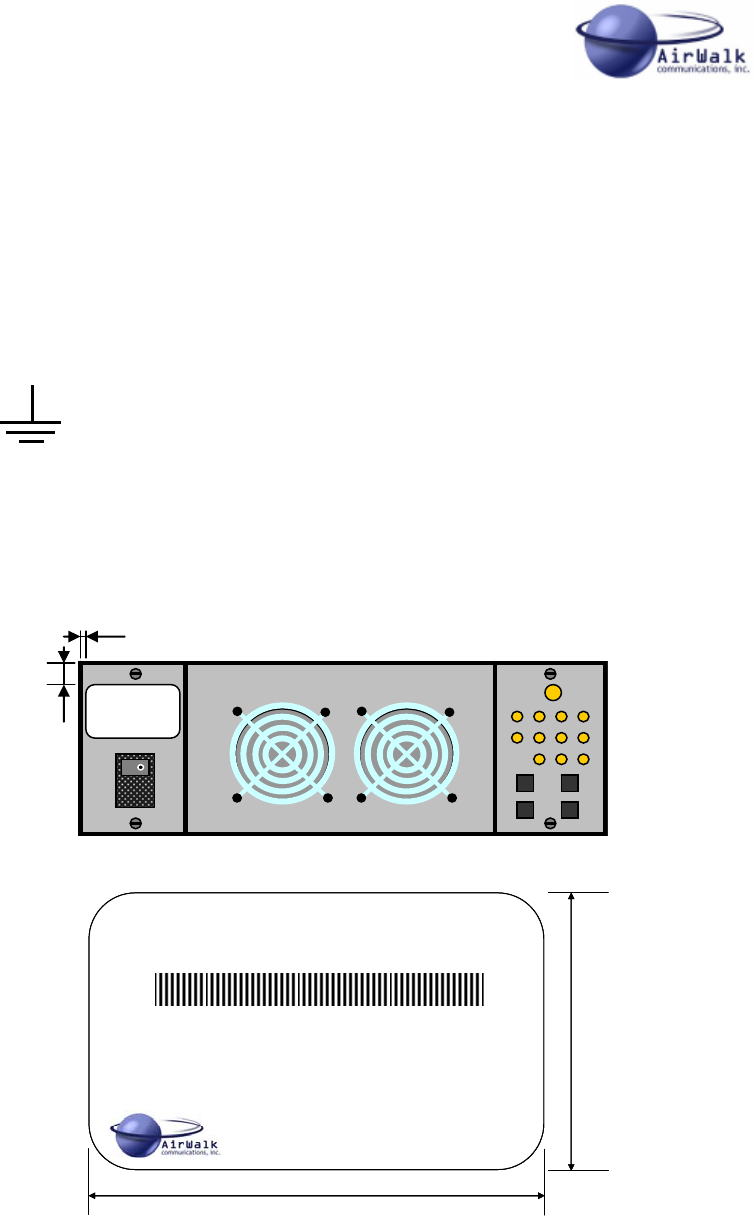
3.3 Maintenance Information
3.3.1 Cleaning
The AirWalk AW 96 units are protected by a high performance paint which does not
require normal maintenance. If paintwork is soiled, it can be cleaned using a damp cloth
after AC power has been disconnected. Do not use liquids or spray cleaning substances
on the unit since property damage or personal injury may result.
3.3.2 Filter Maintenance
The AW 96 Main Unit is equipped with a washable air filter located in a front mounted
drop down door.
This filter should be checked annually for dirt build-up and cleaned if required. Note more
frequent inspections may be needed in dusty environments.
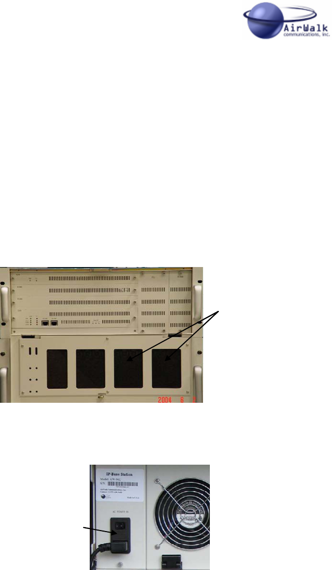
3.3.3 Fuse Replacement
The AW 96 Main Unit contains a 250 V 5A fuse located behind the AC connector cap as
shown in the diagram. Replace the fuse with the same type and ratings.
3.3.4 Other Maintenance
Any other required maintenance must be performed by suitable trained service personnel.
Do not open covers or attempt to repair unit if not suitably trained.
Removable
Fuse Cap
Removable
Fuse Cap
Air Filter Located In
Drop Down Front Door
Air Filter Located In
Drop Down Front Door
AW 96 Series System Installation Manual
___________________________________________________________________________
AirWalk Proprietary and Confidential Page 13 of 72 6/14/2006
3.4 Labeling
3.4.1 Grounding
Proper grounding is recommended to ensure good RF performance in addition to
personnel safety. Antenna systems should also be suitably grounded for good RF
performance.
Grounding connection points on the chassis are identified by this symbol:
3.4.2 Label: Model Identification, FCC Identification, Power
The following label is applied to the AW 96 unit to provide model identification, FCC
identification and rated power supply information.
IP-Base Station
Model : AW96R19AJ1A01 FCC ID : R4HAW96R19AJ1A01
S/N :
76.0
50.0
AC IN: 100-240 VAC 50/60Hz 6A/3A
Fuse: AC 250V 6A (20mm x 5mm)
AirWalk Communications., Inc Contact: +1-972-638-9400
*ZF000096UA*
Made In U.S.A.
IP-Base Station
Model : AW96R19AJ1A01 FCC ID : R4HAW96R19AJ1A01
S/N :
76.0
50.0
AC IN: 100-240 VAC 50/60Hz 6A/3A
Fuse: AC 250V 6A (20mm x 5mm)
AirWalk Communications., Inc Contact: +1-972-638-9400
*ZF000096UA*
Made In U.S.A.
1.0
15.0

AW 96 Series System Installation Manual
___________________________________________________________________________
AirWalk Proprietary and Confidential Page 14 of 72 6/14/2006
3.5 Regulatory Compliance Information
The FCC regulatory compliance information provided in this section is applicable only to
models equipped with an FCC identification number (FCC ID).
3.5.1 Radio Interference (FCC 15.19 Statement)
This device complies with part 15 of the FCC Rules. Operation is subject to the following
two conditions: (1) This device may not cause harmful interference, and (2) this device
must accept any interference received, including interference that may cause undesired
operation.
3.5.2 Unauthorized Modifications (FCC 15.21 Statement)
Persons or parties responsible for operation of this equipment are cautioned that any
changes or modifications not expressly approved by AirWalk Communications
Incorporated could void the user’s authority to operate this equipment.
3.5.3 Digital Device Interference (FCC 15.105 Statement)
This equipment has been tested and found to comply with the limits for a Class B digital
device, pursuant to part 15 of the FCC Rules. These limits are designed to provide
reasonable protection against harmful interference in a residential installation. This
equipment generates, uses, and can radiate radio frequency energy and, if not installed
and used in accordance with the instructions, may cause harmful interference to radio
communications.
3.5.4 RF Exposure (FCC MPC Compliance)
In order to comply with FCC RF Exposure requirements, this device must be installed
and operated in such a way that a minimum separation distance of 20 cm is always
maintained between the antenna and all persons during normal operations.
AW 96 Series System Installation Manual
___________________________________________________________________________
AirWalk Proprietary and Confidential Page 15 of 72 6/14/2006
4 AW 96 System Introduction
4.1 Overview
The AirWalk AW 96 (CDMA-2000 IP-Base Station) product is unique in the way that it
combines both BTS and BSC functionality in one compact platform.
This product is designed for efficiency and optimized to reduce the service providers
CAPEX, and OPEX and at the same time, it increases the number of users per assigned
spectrum.
It provides higher capacity in less space for today’s spectrum hungry data and multi-
media applications.
The AW 96 system provides the following advantages:
• Easily adapted to 3FA/Omni structure.
• Supports 2G (TIA/EIA-95, J-STD-008) and 3G-1X (CDMA2000) standards
• Supports data service transmission of 1.2 kbps to 144 kbps
• Provides 96 basic channel elements.
• Easy repair and support
• Improved reliance
• Provides an ‘All-IP’ solution
• Provides an effective solution for enterprise networks and hot spots.
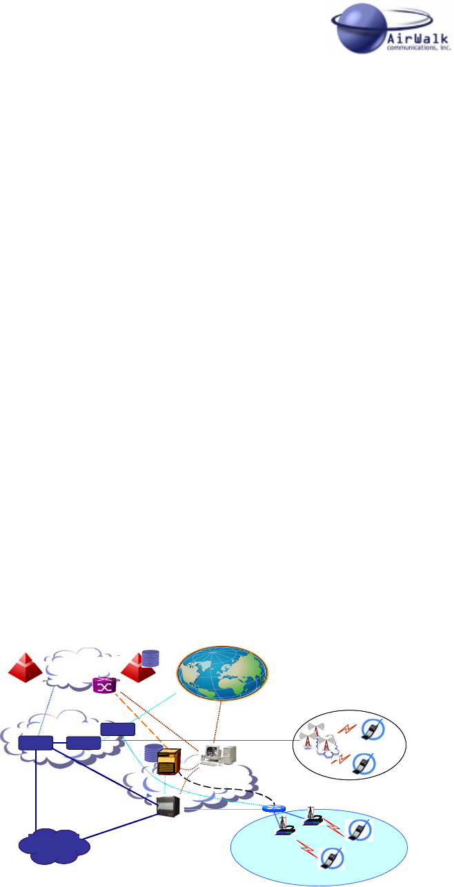
4.2 IP- Base Station (BS) System Description
The AW 96 IP-RAN (Internet Protocol Radio Access Network) is composed of two main
modules: The IP based BSC and the IP based BTS. When an AirWalk IP-RAN is
installed in an ‘ALL-IP’ network the integrated BTS is controlled by the integrated BSC,
and the integrated BSC is controlled by a SS (Soft Switch). Legacy Switching Systems
can also control the integrated BSC through standards based interfaces.
Wireless
Core Network
SS7 Network
SG
Core IP Network
HLR
SMSC
MSC
IP-RAN
(BSC+ BTS)
IP-RAN
PDSN
MG
MG
OAM
Softswitch
Softswitch
BSC
Macro Network
Macro Network
Micro Network
Micro Network
Multi- Media
Internet
Multi- Media
Internet
PSTN
Wireless
Core Network
SS7 Network
SG
Core IP Network
HLR
SMSC
MSC
IP-RAN
(BSC+ BTS)
IP-RAN
PDSN
MG
MG
OAM
Softswitch
Softswitch
BSC
Macro Network
Macro Network
Micro Network
Micro Network
Multi- Media
Internet
Multi-Media
Internet
PSTNPSTN
Figure 4-1 Network Diagram

AW 96 Series System Installation Manual
___________________________________________________________________________
AirWalk Proprietary and Confidential Page 16 of 72 6/14/2006
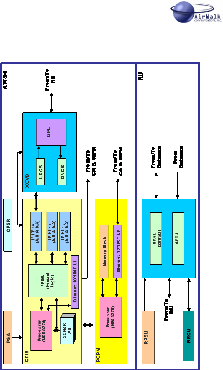
4.3 Hardware Configuration
The IP-BS is a unique modular and stackable combination BSC and BTS platform that is
differentiated from other systems. Other systems have separate BTS and BSC platforms
which adds to cost and complexity. The AirWalk RAN has a structure that combines and
arranges the BSC interface with one 1FA/3Sector BTS in a single package.
The main components are (depending on specific model):
• AW-96 (Main Unit)
o CDPB (Common Digital Processing Board), consisting of:
CPIB (Channel Processor and IF Interface Board)
PCPM (Primary Call Processor Module)
GPSR (Global Positioning System Receiver)
o XCVB (RF Transceiver Board)
o PSA (Power Supply Assembly)
• RU (Remote RF Unit) [3 Sector RU]
o HPAU (High Power Amplifier Unit)
o AFEU (Antenna Front End Unit)
o FANU (Fan Unit)
o RPSU (Remote RF Power Supply Unit) [Separate assembly]
• Integral Omni RU (Remote RF Unit)
o Unified HPAU, AFEU, RPSU in single unit
• Optional Cabinet Mounting
o Some units may be mounted in an optional cabinet
4.3.1 Physical Description
• Main Unit
o Dimension: Max. 482mm(W) x 457mm(D) x 178mm(H)
o 19” EIA Rack x 4 Rack Units
o Weight: 18 kg (3 Sector); 15 kg (Omni)
• Sector RU [3 Sector RU] (less power supply)
o Dimension: Max. 482mm(W) x 362mm(D) x 355mm(H)
o 19” EIA Rack x 8 Rack Units
o Weight: 39 kg
• Sector RU RPSU (AC Power Supply)
o Dimension: Max. 482mm(W) x 446mm(D) x 89mm(H)
o 19” EIA Rack x 2 Rack Units
o Weight: 9 kg
• Integrated Omni RU
o Dimension: Max. 482mm(W) x 410mm(D) x 178mm(H)
o 19” EIA Rack x 4 Rack Units
o Weight: 22 kg
• Optional Self-Contained Mounting Cabinet (including casters)
o Dimension: Max. 546mm(W) x 610mm(D) x 876mm(H)
o 19” EIA Rack x 16 Rack Units mounting space
o Refer to Optional Cabinet Installation Manual
AW 96 Series System Installation Manual
___________________________________________________________________________
AirWalk Proprietary and Confidential Page 17 of 72 6/14/2006
4.3.2 Typical Configurations
The following shows typical component configurations for common applications. Refer to
the model charts for the contents of specific model numbers.
Omni low/medium power systems including MicroCell & MiniCell (1mW/50mW/4W)
- AW 96 Main Unit
Omni Pilot Beacon MacroCell Systems (4W)
- AW 96 Main Unit
Omni High Power MacroCell Systems (20W)
- AW 96 Main Unit
- Integrated Omni RU
Sector Low Power MicroCell Systems (1mW/50mW)
- AW 96 Main Unit
Sector High Power MacroCell Systems (20W)
- AW 96 Main Unit
- Sector RU
- Sector RU PSU (AC power supply)
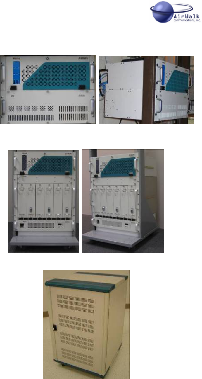
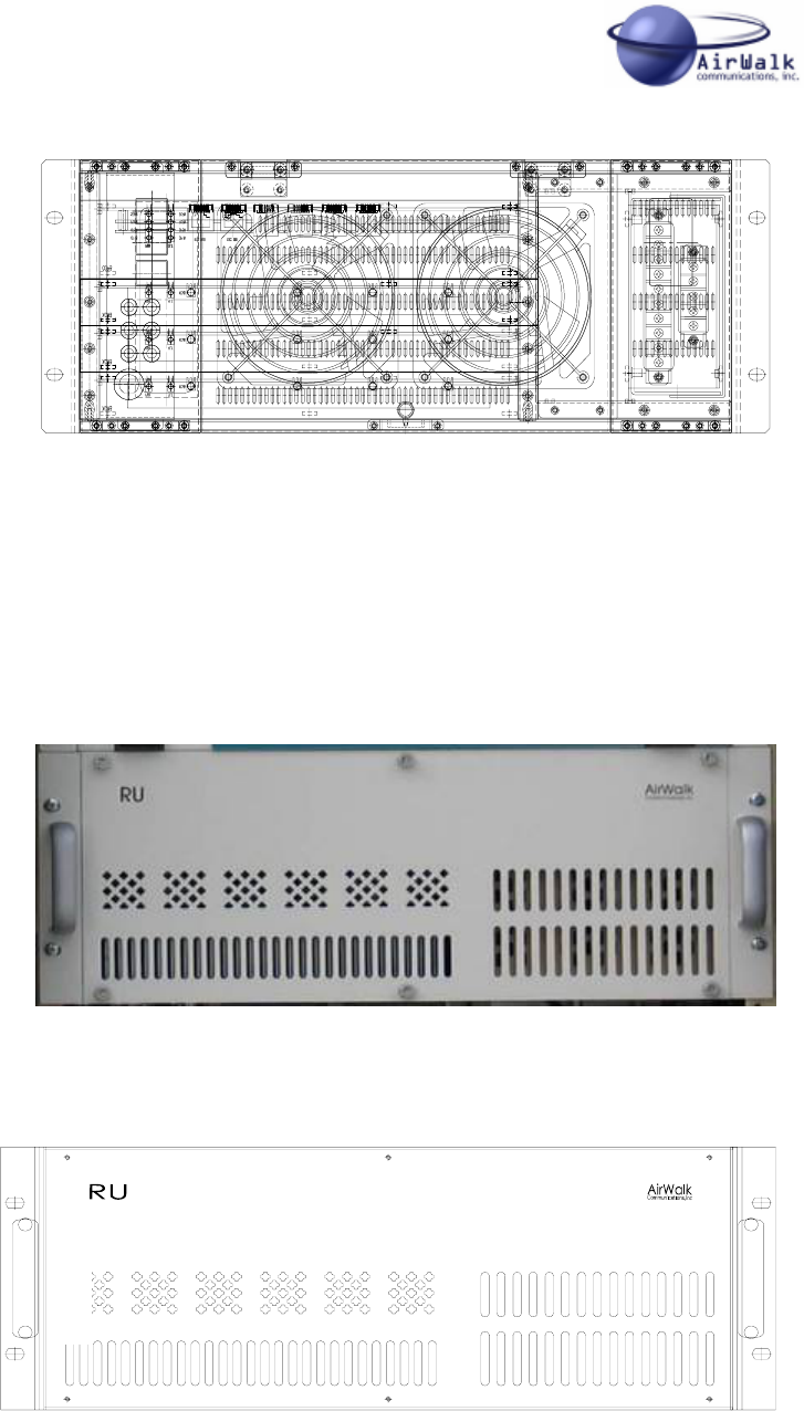
4.3.3 Installation Photographs
The following photographs show typical field installations for AW 96 systems:
Figure 4-2 – Typical AW 96 Microcell, MiniCell & Pilot Beacon Installation
AW 96 Series System Installation Manual
___________________________________________________________________________
AirWalk Proprietary and Confidential Page 18 of 72 6/14/2006
Figure 4-3 – Typical AW 96 with Omni RU (Rack Mounting)
Figure 4-4 – Typical AW 96 & 3 Sector RU (Rack Mounting)
Figure 4-5 – Typical AW 96 & 3 Sector RU with Cabinet Mounting Option
AW 96 Series System Installation Manual
___________________________________________________________________________
AirWalk Proprietary and Confidential Page 19 of 72 6/14/2006
4.4 Block Diagram – AW 96
Figure 4-6 IP-BS Hardware Structure

AW 96 Series System Installation Manual
___________________________________________________________________________
AirWalk Proprietary and Confidential Page 20 of 72 6/14/2006
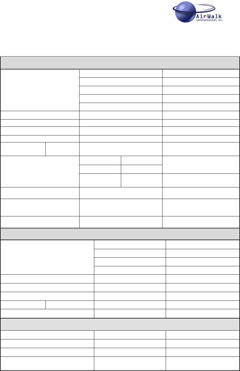
4.5 System Capacities and Specifications
4.5.1 AW 96 Technical Specification
Item Capacity and
Specification Remarks
Up-Link: 2175 ~ 2180 MHz
Down-Link: 1985 ~ 1990MHz Japan PCS Band
Up-Link: 1850 ~ 1910 MHz
Down-Link: 1930 ~ 1990 MHz North American PCS Band
Up-Link: 824 ~ 849 MHz
Down-Link: 869 ~ 894 MHz 800 MHz Cellular Band
Frequency Band
Refer To Model For Sub-Band 450 MHz NMT Band
Sector/FA 3 Sectors/FA
3FA/Omni Each AW 96 Unit
Channel Elements / IP-BS 96CE 3FA (32 CE Omni) IP BTS
Handoff Softer H/O, soft H/O. Hard H/O
Channel pooling Sector
GPS External GPS Antenna One per AW-96
Installation Rack Mountable 4 Rack Units
Cooling Forced Air Front To Rear Flow
IP-Network Interface 10/100 Base-T Ethernet
Transmitter output power 1mW/50mW/5W or 20W w/RU Includes duplexer function
RF Interface 1 Transmit and 1 Receive A RF
signal, 1 Receive B RF signal CDMA 2000 1x
Common Air Interface (CAI) J-STD-008/IS-95-A/IS-95B
/CDMA2000-1x
Channel bandwidth 1.25MHz
Receiving sensitivity Less than 1% FER, when the
power is under -119dBm
Mechanical Specification
RF Input and Output
Connector SMA Female (Input/Output) From/To RU
AC Power Connector IEC
Ethernet Signal Port
Connectors RJ-45
Dimensions ( W x H x D ) 482mm(W) x 457mm(D) x
178mm(H) 4 Rack Units
Weight 18 kg (3 Sector); 15 kg (Omni) AW 96 Main Unit
Table 4-1 – AW-96 Specifications
AW 96 Series System Installation Manual
___________________________________________________________________________
AirWalk Proprietary and Confidential Page 21 of 72 6/14/2006
4.5.2 Integrated Omni RU (Remote RF Unit) Technical Specification
Tx
2160 ~2185 MHz Japan PCS Band
1850 ~1890 MHz N American PCS (A/B/D/E)
1890 ~ 1910 MHz North American PCS (C/F)
824 ~ 849 MHz 800 MHz Cellular Band
Frequency
Refer To Model For SubBand 450 MHz NMT Band
Output Power 43dBm, 20 Watt CDMA
Gain 53 ± 1.0dB
In/Out VSWR 1.5: 1 Output: Isolator Included
Coupling Value 23 ± 1.0dB
Attenuation 1970
~1995MHz 100dBc North American PCS
Fc±885KHz -42dBc Min
Fc±1.98MHz -52dBc Min Max Hold Marker
Spurious Emission
@43dBm(20W)_1FA
Fc±2.75MHz -18dBm Min RBW, VBW=30KHZ,
BW=1MHz
Over Power 45 + 0.7dBm
Over VSWR
Protection Alarm 3:1 30~43dBm
Over Temp. Protection Alarm @ 90o ± 2 o Base Plate Temperature
Rx
1970 ~1995 MHz Japan PCS Band
1930 ~ 1990 MHz North American PCS
869 ~ 894 MHz 800 MHz Cellular Band
Frequency
Refer To Model For SubB 450 MHz NMT Band
Gain 24 ± 1.0dB
Gain Flatness 1.0dB max
In/Out VSWR 1.5: 1
Attenuation 1970 ~1995MHz 100dBc min North American PCS
Noise Figure 2.1dB max
Mechanical Specification
RF Input and Output Connector SMA Female (Input) N Female (Output)
AC Power Connector IEC
Ethernet Signal Port Connector RJ-45
Dimensions ( W x H x D ) 482mm(W) x 457mm(D)
x 178mm(H)) 4 Rack Units
Table 4-2 – Integrated Omni RU Specifications

AW 96 Series System Installation Manual
___________________________________________________________________________
AirWalk Proprietary and Confidential Page 22 of 72 6/14/2006
4.5.3 Sector RU (Remote RF Unit) Technical Specification
Tx
2160 ~2185 MHz Japan PCS Band
1850 ~ 1890 MHz N American PCS (A/B/D/E)
1890 ~ 1910 MHz N American PCS (C/F)
824 ~ 849 MHz 800 Cellular Band
Frequency
Refer To Model For SubBand 450 MHz NMT Band
Output Power 43dBm, 20 Watt CDMA
Gain 53 ± 1.0dB
In/Out VSWR 1.5: 1 Output: Isolator Included
Coupling Value 23 ± 1.0dB
Attenuation 1970
~1995MHz 100dBc North American PCS
Fc±885KHz -42dBc Min
Fc±1.98MHz -52dBc Min Max Hold Marker
Spurious Emission
@43dBm(20W)_1FA
Fc±2.75MHz -18dBm Min RBW, VBW=30KHZ,
BW=1MHz
Over Power 45 + 0.7dBm
Over VSWR
Protection Alarm 3:1 30~43dBm
Over Temp. Protection Alarm @ 90o ± 2 o Base Plate Temperature
Rx
1970 ~1995 MHz Japan PCS Band
1930 ~ 1990 MHz North American PCS
869 ~ 894 MHz 800 MHz Cellular Band
Frequency
Refer to Model For SubB 450 MHz NMT Band
Gain 24 ± 1.0dB
Gain Flatness 1.0dB max
In/Out VSWR 1.5: 1
Attenuation 1970 ~1995MHz 100dBc min North American PCS
Noise Figure 2.1dB max
Mechanical Specification
RF Input and Output Connector SMA Female (Input) N Female (Output)
AC Power Connector IEC
Ethernet Signal Port Connector RJ-45
Dimensions ( W x H x D ) 482mm(W) x 362mm(D)
x 355mm(H) 8 Rack Units
Table 4-3 – Integrated Omni RU Specifications
AW 96 Series System Installation Manual
___________________________________________________________________________
AirWalk Proprietary and Confidential Page 23 of 72 6/14/2006
4.5.4 IP-BS Power Supply & Environment Technical Specification
Input Power Supply
Input Voltage: AC 100Volts ~ 250Volts
Input Frequency: 50Hz ~ 60Hz
Dissipated Power
AW-96 Main Unit: 350 Watt Max (Efficiency 75%)
Integrated Omni RU Unit 400 Watt Max (Efficiency 85%)
Sector RU Unit 1150 Watt Max (Efficiency 85%)
Maximum AW 96 IP-BS 1500 Watt Max (Main Unit & Sector RU)
Environment Specification
Operating Temperature 0o ~ +50 o
Storage Temperature -30 o ~ +60 o
Relative Humidity 5% ~ 95% - Non-condensing
Noise Less than 60dBA, distance 1.5m
Airborne Particle 0 ~ 90 ㎍/㎥
Table 4-3 - Power Supply & Environment Specifications
AW 96 Series System Installation Manual
___________________________________________________________________________
AirWalk Proprietary and Confidential Page 24 of 72 6/14/2006
5 AW 96 Components
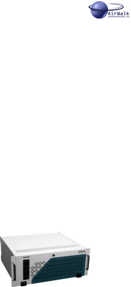
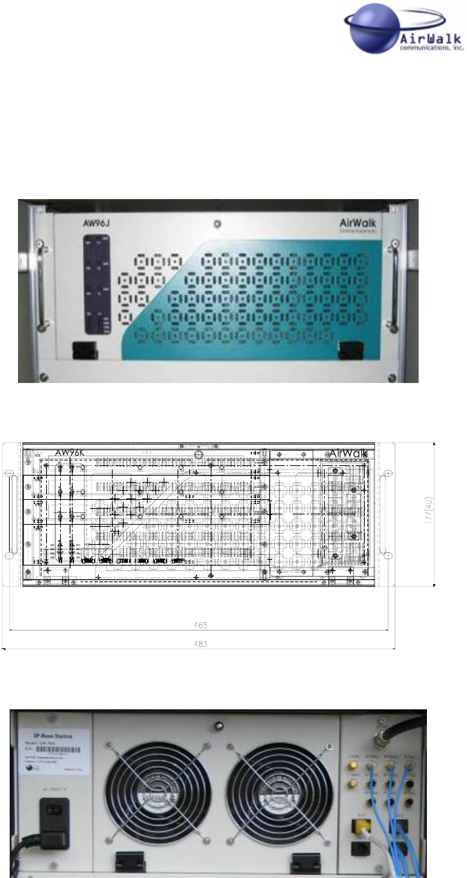
5.1 AW-96 Main Unit
Figure 5-1 AW-96 Main Unit Photo (Front View)
Figure 5-2 AW-96 Main Unit Line Diagram (Front View)
Figure 5-3 AW-96 Main Unit Photo (Back View)
AW 96 Series System Installation Manual
___________________________________________________________________________
AirWalk Proprietary and Confidential Page 25 of 72 6/14/2006
Figure 5-4 AW-96 – Line Diagram (Back View)
5.2 Integral Omni RU (Remote RF Unit) [Omni Configurations]
This is the IP-BS (Internet Protocol BTS System) RF interface system.
The main functions include a 20W power amplifier, RF filtering for Tx and Rx paths, a
duplexer function for to allow connection to an antenna system, and a power supply. All
components are packaged in a unified 4 rack unit package.
Figure 5-5 Integrated Omni RF Unit Photo (Front View)
Figure 5-6 Integrated Omni RU - Line Diagram (Front View)
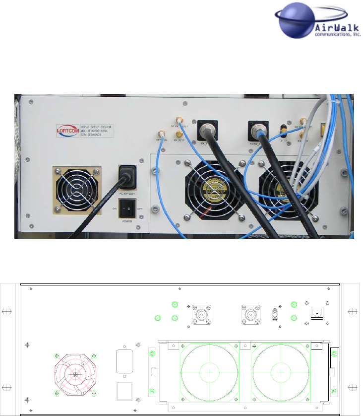
AW 96 Series System Installation Manual
___________________________________________________________________________
AirWalk Proprietary and Confidential Page 26 of 72 6/14/2006
Figure 5-7 Integrated Omni RU (RF Unit) Photo (Rear View)
RF RX_A OUT
RJ- 4 5
RX_A TP
TX/ RX_A ANT
TX_TP
RF TX IN
RF RX_B OUT
RX_B ANT
RX_B TP
Figure 5-8 Integrated Omni RU (RF Unit) - Line Diagram (Back View)
5.3 Sector RU (Remote RF Unit) [Sector Configurations]
This is the IP-BS (Internet Protocol BTS System) sector RF Shelf. The main functions
include a 20W power amplifier for each sector, RF filtering for Tx and Rx paths, a
duplexer function for to allow connection to an antenna system, and a power supply.
The Sector RU system consists of a common chassis in which the following modules are
installed:
• HPAU (High Power Amplifier Unit): 20 Watt power amplifier, one per sector
• AFEU (Antenna Front End Unit): Includes duplexer and LNA functions, 1/sector
• FANU (Fan Unit): Includes fans assemblies for HPAU cooling
• PSU (Power Supply Unit): A separate AC power supply for the RU system

AW 96 Series System Installation Manual
___________________________________________________________________________
AirWalk Proprietary and Confidential Page 27 of 72 6/14/2006
Figure 5-9 Sector RU Photo (Front View)
Figure 5-10 Sector RU Line Diagram (Front View)
Figure 5-11 Sector RU Line Diagram (Rear View)
AW 96 Series System Installation Manual
___________________________________________________________________________
AirWalk Proprietary and Confidential Page 28 of 72 6/14/2006
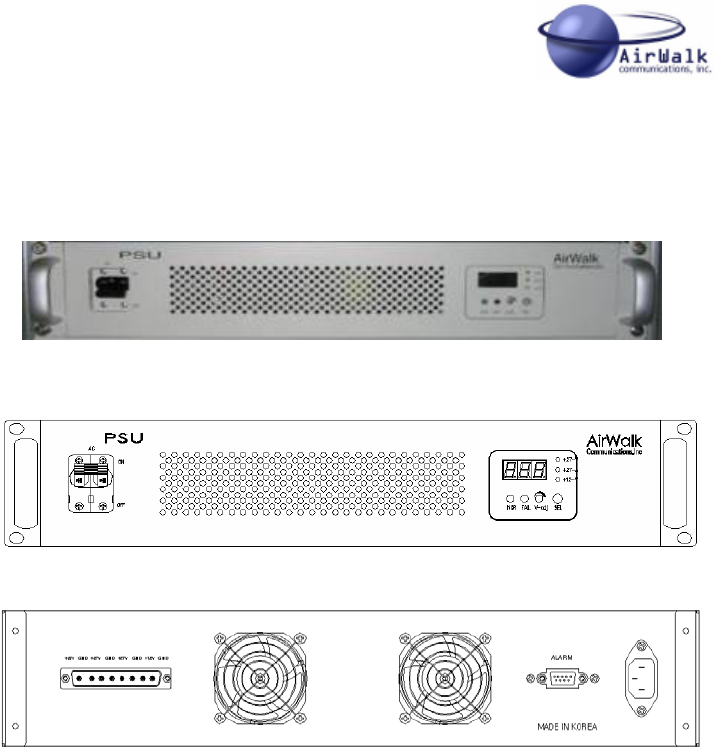
Each AC powered Sector RU system is also equipped with a separate Power Supply Unit
which provides conditioned power for the RU system.
Figure 5-12 Sector RU PSU - Photo (Front View)
Figure 5-13 RPSU – Line Diagram (Front and Back Views)
AW 96 Series System Installation Manual
___________________________________________________________________________
AirWalk Proprietary and Confidential Page 29 of 72 6/14/2006
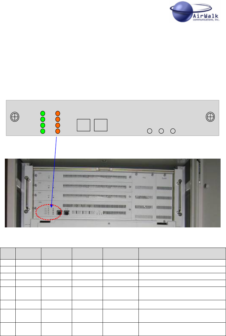
5.4 Component LED Configuration
5.4.1 CDPB (Common Digital Processing Block)
LED status indicators are provided on the AW-96 CDPB module. LED functions are
described in the following pictures and tables.
CPIB
GPSR
PCPM
SCPM
CDPB PWR FLT
BTS
MMI BSC
MMI RESET
CPIB
PCPM SCPM
Figure 5-9 CDPB Panel Diagram
Figure 5-10 - CDPB Panel Photo
Name Color On Off Note
1 CPIB Green Normal Abnormal CPIB power on/off indicator
2 GPSR Green Normal Abnormal GPSR power on/off indicator
3 PCPM Green Normal Abnormal PCPM power on/off indicator
4 SCPM Green Normal Abnormal SCPM power on/off indicator
5 CPIB Orange Abnormal Normal Check function of CPU in CPIB
Board and ALARM
6 GPSR Orange Abnormal Normal GPSR alarm on/off indicator
7 PCPM Orange Abnormal Normal Check function of CPU in
PCPM Board and ALARM
8 SCPM Orange Abnormal Normal Check function of CPU in
SCPM Board and ALARM
Table 5-1 – CDPB Indicator Codes
NOTE: AW-96 models are NOT normally equipped with an SCPM (Secondary Call
Processor Module), therefore these indicators are not used in most system applications.

AW 96 Series System Installation Manual
___________________________________________________________________________
AirWalk Proprietary and Confidential Page 30 of 72 6/14/2006
XCVB
The XCVB module is equipped with 2 indicators. LED functions are described in the
following pictures and tables.
XCVB
PWR
FLT
Figure 5-11 - XCVB Panel Diagram
Figure 5-12 XCVB Panel Photo
Name Color On Off Note
1 PWR Green Normal Abnormal XCVB power on/off indicator
2 FLT Orange Abnormal Normal XCVB alarm on/off indicator
Table 5-2 - XCVB Indicator Code Key
AW 96 Series System Installation Manual
___________________________________________________________________________
AirWalk Proprietary and Confidential Page 31 of 72 6/14/2006
5.4.2 Sector RU Power Supply Unit (PSU) [AC powered models only]
The RU PSU (Power Supply Unit) is equipped with both indicators and a small numeric
display. The indicator and display functions relate only to power supply operation for the
RU and are described in the following pictures and tables.
Note that only AC powered models are equipped with the PSU module.
PSU
NOR FAIL V-adj SEL
+27 -V
+27 - A
+12 -V
Figure 5-6 - RPSU Panel Diagram
Figure 5-7 RPSU Panel Photo
Name Color On Off Note
1 NOR Green Normal Abnormal RPSU power normal
operation indicator
2 FAIL RED Fail Normal RPSU power fail indicator
3 +27-V Green Select Non-Select
+27V Voltage select by
SEL push switch
4 +27-A Green Select Non-Select
+27V Current select by SEL
push switch
5 +12-V Green Select Non-Select
+12V Voltage select by
SEL push switch
Table 5-1 - RPSU Indicator Codes
AW 96 Series System Installation Manual
___________________________________________________________________________
AirWalk Proprietary and Confidential Page 32 of 72 6/14/2006
6 AW 96 Integrated Omni RU Interface Cabling
6.1 RF Cabling – Integrated RU Omni Configuration
The AW 96 transmitter exciter output and diversity receiver inputs are connected to the
RU which contains the duplexer, LNA and HPA functions. Connect using jumper cables
as shown in Figure 6-1 (1). Use suitable cables as provided with the AW 96 system and
shown in figure 6-2.
Connect external diversity antenna systems as shown in Figure 6-1 (2). External antenna
connectors are “N-Type”.
Figure 6-1 Integrated Omni RU RF Cabling Diagram
GPSANT
RF RXB(a) RF RXA(a) RF TX
(a)
RF RXB( b ) RF RXA(b ) RF TX
(b)
RF RXB( r ) RF RXA(r) RF TX ( r)
T_EVEN
T_10MHz
RU IF BSC IF
ENV IF BTS IF
RF RX_A OUT
RJ- 4 5
RX_ A T P
TX/ RX_A ANT
TX_TP
RF TX IN
RF RX_ B OUT
RX_ B ANT
RX_B TP
RF Antenna
1
2
GPSANT
RF RXB(a) RF RXA(a) RF TX
(a)
RF RXB( b ) RF RXA(b ) RF TX
(b)
RF RXB( r ) RF RXA(r) RF TX ( r)
T_EVEN
T_10MHz
RU IF BSC IF
ENV IF BTS IF
RF RX_A OUT
RJ- 4 5
RX_ A T P
TX/ RX_A ANT
TX_TP
RF TX IN
RF RX_ B OUT
RX_ B ANT
RX_B TP
RF Antenna
1
2
AW 96 Series System Installation Manual
___________________________________________________________________________
AirWalk Proprietary and Confidential Page 33 of 72 6/14/2006
RG316DS
Coaxial Cable
L
Figure 6-2 AW-96 to RU RF Cable Specification
6.2 Electric Power Cable Wiring
Connect AW-96 and Integrated Omni RU to suitable AC power sources as shown in Figure 6-3.
Use only the AC power cable provided with AW 96 unit for safe operation.
Figure 6-3 AW 96 Power Cabling
AC Power
GPSANT
RF RXB( a) RF RXA( a) RF TX
(a)
RF RXB(b) RF RXA( b ) RF TX
(b)
RF RXB( r) RF RXA( r) RF TX (r)
T_EVEN
T_10MHz
RU IF BSC IF
ENV IF BTS IF
RF RX_ A OUT
RJ- 45
RX_A TP
TX/ RX_A ANT
TX_TP
RF TX I N
RF RX_ B OUT
RX_ B ANT
RX_B TP
AC Power
GPSANT
RF RXB( a) RF RXA( a) RF TX
(a)
RF RXB(b) RF RXA( b ) RF TX
(b)
RF RXB( r) RF RXA( r) RF TX (r)
T_EVEN
T_10MHz
RU IF BSC IF
ENV IF BTS IF
RF RX_ A OUT
RJ- 45
RX_A TP
TX/ RX_A ANT
TX_TP
RF TX I N
RF RX_ B OUT
RX_ B ANT
RX_B TP
AW 96 Series System Installation Manual
___________________________________________________________________________
AirWalk Proprietary and Confidential Page 34 of 72 6/14/2006
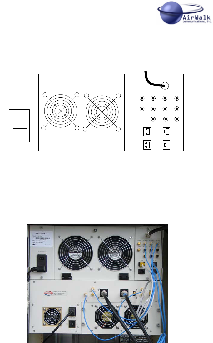
6.3 Ethernet Cable Wiring
Connect Integrated Omni RU to AW-96 using supplied Ethernet cable as shown in Figure
6-4 (1). Connect external Ethernet connections to the BTS and BSC Ethernet ports on
the AW-96 (2).
Figure 6-4 Ethernet Cable Wiring
6.4 GPS Antenna Cable Wiring
Connect the external GPS antenna RF cable to the GPS antenna port on the AW-96 unit
as shown in Figure 7-5. The GPS connector is an “TNC” connector. The AirWalk GPS
antenna kit (AWANC001GPCA01) includes a GPS antenna, mounting hardware and a
25m cable (RG-58 or better).
Note the GPS antenna must located outside in a position to see the general sky. The
GPS antenna must see at least 4 GPS satellites in the sky to receive enough time
information for proper system operation.
GPSANT
RF RXB(a ) RF RXA( a) RF TX
(a)
RF RXB( b) RF RXA(b ) RF TX
(b)
RF RXB(r ) RF RXA( r) RF TX (r )
T_EVEN
T_10MHz
RU IF BSC IF
ENV IF BTS IF
RF RX_ A OUT
RJ- 45
RX_A TP
TX/ RX_A ANT
TX_TP
RF TX I N
RF RX_ B OU T
RX_ B ANT
RX_B TP
12
GPSANT
RF RXB(a ) RF RXA( a) RF TX
(a)
RF RXB( b) RF RXA(b ) RF TX
(b)
RF RXB(r ) RF RXA( r) RF TX (r )
T_EVEN
T_10MHz
RU IF BSC IF
ENV IF BTS IF
RF RX_ A OUT
RJ- 45
RX_A TP
TX/ RX_A ANT
TX_TP
RF TX I N
RF RX_ B OU T
RX_ B ANT
RX_B TP
12
AW 96 Series System Installation Manual
___________________________________________________________________________
AirWalk Proprietary and Confidential Page 35 of 72 6/14/2006
Figure 6-5 GPS Antenna Cable Wiring
6.5 Photograph Of Typical Cable Wiring
Figure 6-6 shows the actual cabling found in a typical system installation.
Figure 6-6 – Integrated RU Field Installation Photograph
GPSANT
RF RXB( a) RF RXA(a) RF TX
(a)
RF RXB( b) RF RXA(b ) RF TX
(b)
RF RXB (r ) RF RXA(r) RF TX (r)
T_EVEN
T_10MHz
RU IF BSC IF
ENV IF BTS IF
GPS Antenna
GPSANT
RF RXB( a) RF RXA(a) RF TX
(a)
RF RXB( b) RF RXA(b ) RF TX
(b)
RF RXB (r ) RF RXA(r) RF TX (r)
T_EVEN
T_10MHz
RU IF BSC IF
ENV IF BTS IF
GPS Antenna

AW 96 Series System Installation Manual
___________________________________________________________________________
AirWalk Proprietary and Confidential Page 36 of 72 6/14/2006
7 AW 96 Sector RU Interface Cabling
7.1 RF Cabling – Sector RU Configuration (3 Sector)
The AW 96 transmitter exciter output and diversity receiver inputs are connected to the
Sector RU which contains the duplexer, LNA (Low Noise pre-Amplifier) and HPA (High
Power Amplifier) functions. Connect using jumper cables as shown in Figure 7-1.
Use only the cables supplied with the RU system for interconnection to the AW-96.
Cables are labeled for ease of installation. See Figure 7-2 for cable specification.
Figure 7-1 AW-96 to Sector RU RF Cable Connections
GPSANT
RF RXA(a) RF TX (a)
RF TX(b)
RF RXB(r) RF RXA(r) RF TX (r)
T_EVEN
T_10MHz
RU IF BSC IF
ENV IF BTS IF
RF RXB(a)
RF RXB(b) RF RXA(b)
αSector
βSector
γSector
To “γ”
Sector
Antennas
To “β”
Sector
Antennas
To “α”
Sector
Antennas
GPSANT
RF RXA(a) RF TX (a)
RF TX(b)
RF RXB(r) RF RXA(r) RF TX (r)
T_EVEN
T_10MHz
RU IF BSC IF
ENV IF BTS IF
RF RXB(a)
RF RXB(b) RF RXA(b)
GPSANT
RF RXA(a) RF TX (a)
RF TX(b)
RF RXB(r) RF RXA(r) RF TX (r)
T_EVEN
T_10MHz
RU IF BSC IF
ENV IF BTS IF
RF RXB(a)
RF RXB(b) RF RXA(b)
αSector
βSector
γSector
To “γ”
Sector
Antennas
To “γ”
Sector
Antennas
To “β”
Sector
Antennas
To “β”
Sector
Antennas
To “α”
Sector
Antennas
To “α”
Sector
Antennas

AW 96 Series System Installation Manual
___________________________________________________________________________
AirWalk Proprietary and Confidential Page 37 of 72 6/14/2006
It is important to ensure transmit and receive connections are made correctly to prevent
damage or field operational problems such as:
- Damage due to transmitting into a receiver port
- Crossed over diversity receive ports
- Crossed over sectors which could disrupt RF system design/optimization
Connect the external transmission lines from the diversity antenna systems to the RU
Antenna connections as shown in Figure 7-1. External connectors are “N-Type”.
Note that transmission line (or jumpers to transmission line) type and length will impact
the overall link budget calculations for the cell site. Be sure to include these losses in the
RF system design calculations for coverage.
RG316DS
Coaxial Cable
L
Figure 7-2 AW-96 to RU RF Cable Specification
7.2 RU Power Supply Interconnect Wiring
Connect the power interconnect cable between the RU main assembly and the RU power
supply as shown in Figure 7-3. Use only the cable supplied with the RU system for this
purpose. Tighten connector captivating screws to prevent accidental disconnection.
Connect the RU power supply alarm interconnect cable between the RU main assembly
and the RU power supply as shown in Figure 7-3. Use only the cable supplied with the
RU system for this purpose. Tighten connector captivating screws to prevent accidental
disconnection.
7.3 Ethernet/Serial Cable Wiring
Connect RU interface cable between the AW-96 RU I/F port and the RU RU I/F port as
shown in Figure 7-3. This connection allows the AW-96 to communication with RU
system for the purposes of transferring measurements, alarms and control functions. Use
only the serial cable supplied with the RU system for this purpose. Ensure the RJ-45
connectors are properly seated (“click”) to prevent accidental disconnection.
Connect the external Ethernet connections (cable not supplied) from the local Ethernet
switch or hub at the cell site to the BTS and BSC Ethernet ports on the AW-96 as shown
in Figure 7.3. Use category 5 Ethernet cable (or better) for best performance.
AW 96 Series System Installation Manual
___________________________________________________________________________
AirWalk Proprietary and Confidential Page 38 of 72 6/14/2006
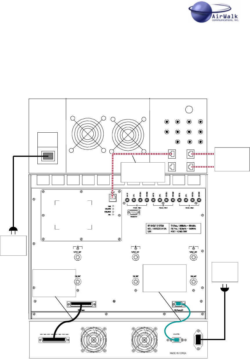
7.4 Electric Power Cable Wiring
Connect AW-96 and Sector RU system to suitable AC power sources as shown in Figure
7-3. Use only the AC power cables provided with AW 96 unit and the RU unit to ensure
continued safe operation.
Figure 7-3 AW-96 to RU Serial/Ethernet/Power Connections
GPSANT
RF RXA(a) RF TX (a)
RF TX(b)
RF RXB(r) RF RXA(r) RF TX (r)
T_EVEN
T_10MHz
RU IF BSC IF
ENV IF BTS IF
RF RXB(a)
RF RXB(b) RF RXA(b)
AC
Power
Power
Interconnect
Cable
Alarm
Interconnect
Cable
To Local
Ethernet
Switch/Hub
RU Interface
Cable
AC
Power
GPSANT
RF RXA(a) RF TX (a)
RF TX(b)
RF RXB(r) RF RXA(r) RF TX (r)
T_EVEN
T_10MHz
RU IF BSC IF
ENV IF BTS IF
RF RXB(a)
RF RXB(b) RF RXA(b)
GPSANT
RF RXA(a) RF TX (a)
RF TX(b)
RF RXB(r) RF RXA(r) RF TX (r)
T_EVEN
T_10MHz
RU IF BSC IF
ENV IF BTS IF
RF RXB(a)
RF RXB(b) RF RXA(b)
AC
Power
Power
Interconnect
Cable
Alarm
Interconnect
Cable
To Local
Ethernet
Switch/Hub
RU Interface
Cable
AC
Power
AW 96 Series System Installation Manual
___________________________________________________________________________
AirWalk Proprietary and Confidential Page 39 of 72 6/14/2006
7.5 GPS Antenna Cable Wiring
Connect the external GPS antenna RF cable to the GPS antenna port on the AW-96 unit
as shown in Figure 7-5. The GPS connector is an “TNC” connector. The AirWalk GPS
antenna kit (AWANC001GPCA01) includes a GPS antenna, mounting hardware and a
25m cable (RG-58 or better).
Note the GPS antenna must located outside in a position to see the general sky. The
GPS antenna must see at least 4 GPS satellites in the sky to receive enough time
information for proper system operation.
Figure 7-5 GPS Antenna Cable Wiring
GPSANT
RF RXB( a) RF RXA(a) RF TX
(a)
RF RXB( b) RF RXA(b ) RF TX
(b)
RF RXB (r ) RF RXA(r) RF TX (r)
T_EVEN
T_10MHz
RU IF BSC IF
ENV IF BTS IF
GPS Antenna
GPSANT
RF RXB( a) RF RXA(a) RF TX
(a)
RF RXB( b) RF RXA(b ) RF TX
(b)
RF RXB (r ) RF RXA(r) RF TX (r)
T_EVEN
T_10MHz
RU IF BSC IF
ENV IF BTS IF
GPS Antenna
AW 96 Series System Installation Manual
___________________________________________________________________________
AirWalk Proprietary and Confidential Page 40 of 72 6/14/2006
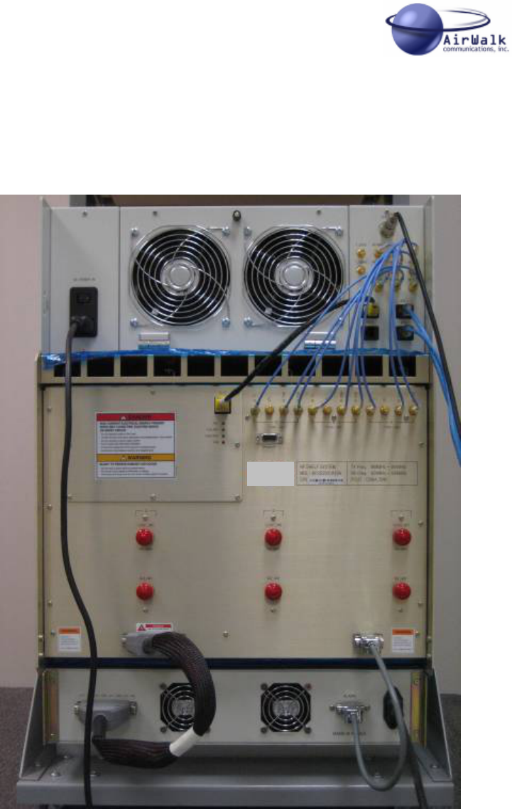
7.6 Photograph Of Typical Cable Wiring
Figure 7-6 shows the cabling found in a typical Sector RU system installation.
Figure 7-6 Sector RU Field Installation Photograph
AW 96 Series System Installation Manual
___________________________________________________________________________
AirWalk Proprietary and Confidential Page 41 of 72 6/14/2006
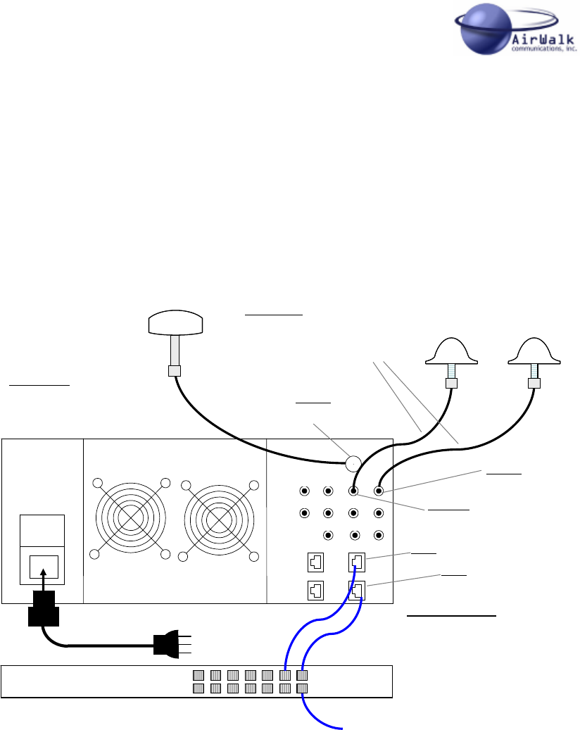
8 AW 96 Low Power (PicoCell/MicroCell) Cabling
The following connections are required for AW 96 stand-alone applications, including
PicoCell and MicroCell. AW 96 units for these applications are normally configured for
50mW power output and are equipped with an internal duplexer function which requires
only a single antenna for normal operation. A second diversity receiver connection is
provided if required for the application
Connect power, Ethernet, GPS and RF antenna cables as shown in the diagram below.
Use only the AC power cables provided with AW 96 unit unit to ensure continued safe
operation.
Use recommended RF and Ethernet cables or equivalent.
Use the optional AirWalk GPS antenna kit (AWANC001GPCA01) when GPS is required
for the application. This kit includes a GPS antenna, mounting hardware and a 25m
cable.
Note the GPS antenna must located outside in a position to see the general sky. The
GPS antenna must see at least 4 GPS satellites in the sky to receive enough time
information for proper system operation when GPS is required.
GPSANT
RF RXB(a) RF RXA(a) RF TX
(a)
RF RXB(b) RF RXA(b) RF TX
(b)
RF RXB(r) RF RXA(r) RF TX (r)
T_EVEN
T_10MHz
RU IF BSC IF
ENV IF BTS IF
GPSANT
RF RXB(a) RF RXA(a) RF TX
(a)
RF RXB(b) RF RXA(b) RF TX
(b)
RF RXB(r) RF RXA(r) RF TX (r)
T_EVEN
T_10MHz
RU IF BSC IF
ENV IF BTS IF
10/100 Ethernet Switch10/100 Ethernet Switch
Main
Tx/Rx
Antenna
Optional
Diversity
Antenna
RF Cables
Cables: 2, one Tx, one Rx
Connectors: SMA M – N Type M
Cable Type: RG-400 or equiv
RF TX (α)
SMA F
Connector
GPS Cable
Connectors: TNC M-TNC M
Cable Type: RG-58 or equiv
Outdoor GPS
Antenna
GPS ANT
TNC F
Connector
Ethernet Cables
Cables: 2, one BSC I/F, one BTS I/F
Connectors: RJ-45
RF RXA (α)
SMA F
Connector
BSC IF
RJ-45
BTS IF
RJ-45
To WCA/MG & BSM (Ethernet)
Supplied AC
Power Cord
Standard
IEC Connector

AW 96 Series System Installation Manual
___________________________________________________________________________
AirWalk Proprietary and Confidential Page 42 of 72 6/14/2006
9 Frequency Setting Procedures
9.1 BSM Management
The AW-96 series base stations are normally managed by the centrally located BSM
(Base Station Manager) system which communicates with the AW-96 over an IP
connection.
The BSM will download system software and configuration information which includes the
physical FA (Frequency Assignment) for each base station. The base station will tune to
the correct frequency as defined by the BSM configuration files.
Refer to the BSM operations manual for instructions on base station remote configuration.
9.2 Local FA Setting
It may required to set the AW-96 series base station physical FA (frequency assignment)
locally for specialized test purposes or when the BSM connection is unavailable (for
example during early BTS installations). This can be done using the local MMI (Man
Machine Interface) port and a local PC.
The configuration data downloaded from the BSM will override local settings when BSM
connections are established.
Refer to the MMI instruction manual for further information on other commands.
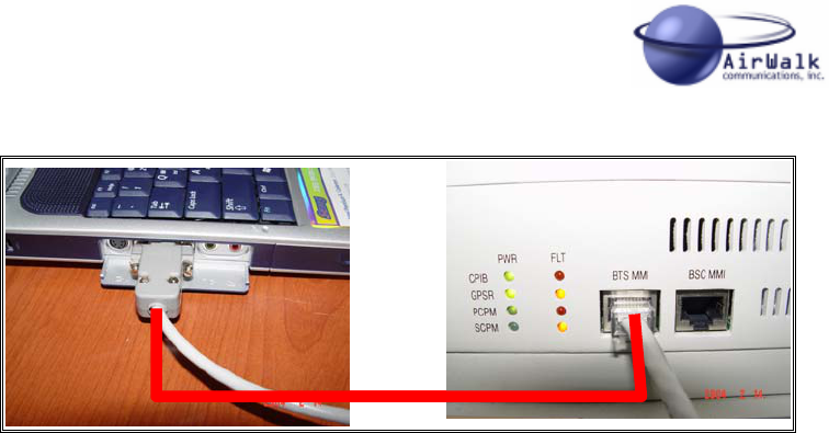
9.2.1 MMI Connection
Connect the serial port of the PC to the “BTS MMI” port on the AW-96 front panel. Use
the cable described in section 8.3.1 and the following port settings:
9600 baud
8 bit
No Parity
1 stop bit
No flow control
AW 96 Series System Installation Manual
___________________________________________________________________________
AirWalk Proprietary and Confidential Page 43 of 72 6/14/2006
9.2.2 FA Change Procedure
The following menu driven commands will permit local change of the FA.
Step 1
At the prompt enter the following:
> pn3383 // this will take you to the menu screen which looks something like this:
================= PN 3383 ====================
1. Tx Test
2. Rx Test
3. ParameterSetup
4. Rf Gain Display
5. xcvbSetup
6. ampSetup
7. Normal Gain Display
8. MakeTestCall
9. callClear
10. Overhead Calibration Control
11. Test Phone Setup (619 2221001)
12. Handoff Test
0. Exit
--------------------------------------------------
Select Number ===>
Step 2

AW 96 Series System Installation Manual
___________________________________________________________________________
AirWalk Proprietary and Confidential Page 44 of 72 6/14/2006
Enter the following:
Select number => 5 // it will take you to the below menu screen.
================= Xcvb Setup ====================
1. Change Ch
2. Tx On
3. Tx Off
4. Rx_Main_AGC ON
5. Rx_Main_AGC OFF
6. Rx_Sub_AGC ON
7. Rx_Sub_AGC OFF
8. Set RxMain ATT
9. Set RxSub ATT
10. Set Tx Att
11. Xcvb Status
12. showXcvrAttGain
0. Exit
--------------------------------------------------
Select Input Number =====>
Step 3
Enter the following:
Select Input Number => 1 // choosing 1 will take you to the below menu.
ALPHA : xcvrChangeCh Num [001 ~ 1500] [1175] [/0:Exit]==>
Step 4
From the above menu, type the new channel desired (CDMA channels from 1 to 1500)
and 0 to exit. Note that for 3 sector base stations Step 3 must be repeated for each
sector (alpha, beta, and gamma).
Note that only standard CDMA channel numbers within the designated band capability of
the radio will be accepted by the base station.

AW 96 Series System Installation Manual
___________________________________________________________________________
AirWalk Proprietary and Confidential Page 45 of 72 6/14/2006

AW 96 Series System Installation Manual
___________________________________________________________________________
AirWalk Proprietary and Confidential Page 46 of 72 6/14/2006
10 Installation Procedures
This Section gives definitions and instructions for installing the AW-Series IP-RAN and for
connecting it to the wireless carriers infrastructure. It contains detailed definitions needed
for completing site Installation Checklist (Appendix B).
10.1 Installation Verification
Before installing the equipment, it is necessary to verify the following:
10.1.1 Verify Customer Contact & Equipment location
10.1.1.1 Contact Customer1
1) Verify contact name check Site Preparation Planning Checklist Appendix B.
2) Verify contact phone number.
3) Introduce yourself to the Customer contact.
4) Introduce Installation team (if more than one person on team).
5) Verify that all current customer contacts are listed.
a) Verify that contacts can solve problems within a timely manner for:
i) Power Connection(s),
ii) T1 Connection(s),
iii) LAN Connection(s),
iv) If not, have main customer contact provide names and method of
contacting.
6) Determine when contacts are available for help (e.g.; Time of day, day of week.).
7) Obtain any site access or security requirements (e.g.: ID Badges, Card-keys, Keys,
Access codes) required to access installation site.
8) Indicate all changes on checklist.
10.1.1.2 Locate AW-SERIES IP-RAN Equipment.2
1) Determine where AW-SERIES IP-RAN is stored.
2) Check for any visible shipment damage.
1 NOTE: Make sure all changes are sent to the Installation Coordinator Immediately.
2 NOTE: If any visible damage contact the Installation Coordinator immediately.

AW 96 Series System Installation Manual
___________________________________________________________________________
AirWalk Proprietary and Confidential Page 47 of 72 6/14/2006
10.1.1.3 Locate and verify floor space.
1) Determine where the AW-SERIES IP-RAN is to be installed (Refer to site diagram
in Appendix B).
2) Verify that there is enough space to safely install it (Refer to site diagram in
Appendix B).
10.1.2 Uncrate and arrange for packing material disposal
1) Carefully unpack the AW-SERIES IP-RAN and related components from packing
material.
2) Check for any shipment damage.3
3) Be certain that all components match system order.4
4) Make arrangements with customer contact on where, when, and how to dispose of
all AW-SERIES IP-RAN packing material.
10.1.3 Verify location of all Facility distribution points
(main and intermediate)
10.1.3.1 Power Check.
10.1.3.1.1 Power Location
1) Locate the customer provided power connection.
a) There should be a –48VDC connection for DC powered models (if required).
b) There should be a 120 or 240 VAC connection for AC powered models (if
required).
10.1.3.1.2 Verify Connector.
1) An 8 AWG three wire stranded cable to connect to a WECO DC terminal block
connector is required for –48VDC (if required).
2) A 6ft (1.84m) e conductor type SJT cables with standard grounded connector is
required for 110VAC connection (if required).
3 NOTE: Note any damage on shipping report, and Installation Checklist. Contact
the Installation Coordinator immediately
4 NOTE: If components do not match the system order, contact the Coordinator
immediately.

AW 96 Series System Installation Manual
___________________________________________________________________________
AirWalk Proprietary and Confidential Page 48 of 72 6/14/2006
10.1.3.1.3 Voltage
1) Using a power meter check for correct voltage.
a) –48VDC range is 40VDC to 57VDC (if required).
b) 120 VAC range is 90 VAC to 132 VAC (if required).
c) 240 VAC range is 180 VAC to 264 VAC (if required).
10.1.3.1.4 Amps
1) Check cables to determine if they will handle required Amps.
a) –48VDC should be able to support 27.9 Amps.
b) 120 VAC should support 15 Amps, 240 VAC should support 7.5 Amps
10.1.3.1.5 LAN Facilities check.
1) Location – Locate the customer provided LAN connections.
2) Verify IP Address (Site Prep Checklist Appendix B).
3) Verify Connector is an RJ45 (if not contact customer).
4) Connect Laptop and Ping IP Address.
5) Prepare a site IP addressable device diagram showing the IP address for each
device at the base station site. This diagram is essential for any needed
troubleshooting activities.
6) Post the diagram at the site and return a copy to the customer’s maintenance center
and a copy to the AirWalk customer service center:
AirWalk Customer Service Centre
1830 North Greenville Ave.,
Richardson, Texas 75081
10.2 AW-SERIES IP-RAN Install Procedures
10.2.1 Install AW-SERIES IP-RAN Cabinet
Move AW-SERIES IP-RAN to location.
Secure AW-SERIES IP-RAN in designated location
(Bolt down or Secure Wheels if provided).
10.2.2 Verify All Internal System Connections
To verify all internal connections refer to the Section and Figures in the following Table
for proper cable installation.
AW 96 Series System Installation Manual
___________________________________________________________________________
AirWalk Proprietary and Confidential Page 49 of 72 6/14/2006
Section Description Reference 3
6.1 RF Cable - AW-96 to RU
Figure 6-1
Use RF cables
supplied with
AW-96.
6.3 Ethernet Cable – AW-96 to RU Figure 6.4
Table 7-1 - Internal System Cable Reference
10.2.3 External System Connections5
To install new internal connections refer to the Section and Figures in the following Table
for proper cable installation.
Section Description Reference 3
6.1 External Diversity Antenna System Figure 6-2
6.2 Electrical Power Cable
Figure 6-3
Use AC power
cables supplied
with AW-96.
6.3 External BSC & BTS Ethernet Cable Figure 6-4
6.4 External GPS Antenna Cable Figure 6-5
Table 7-2 - External System Cable Reference
10.2.4 Connect Power to Cabinet
Connect -48VDC to DC distribution panel (if applicable).
Connect 120VAC or 240VAC to Rack AC distribution panel (if applicable).
10.2.5 Connect Communications Facilities
Connect LAN Facilities to BSC
Connect LAN Facilities to BTS.
5 WARNING: Make sure all system power supplies are turned off. All
breakers/Fuses are pulled on all main and intermediate panels. Then proceed with
the Installation.
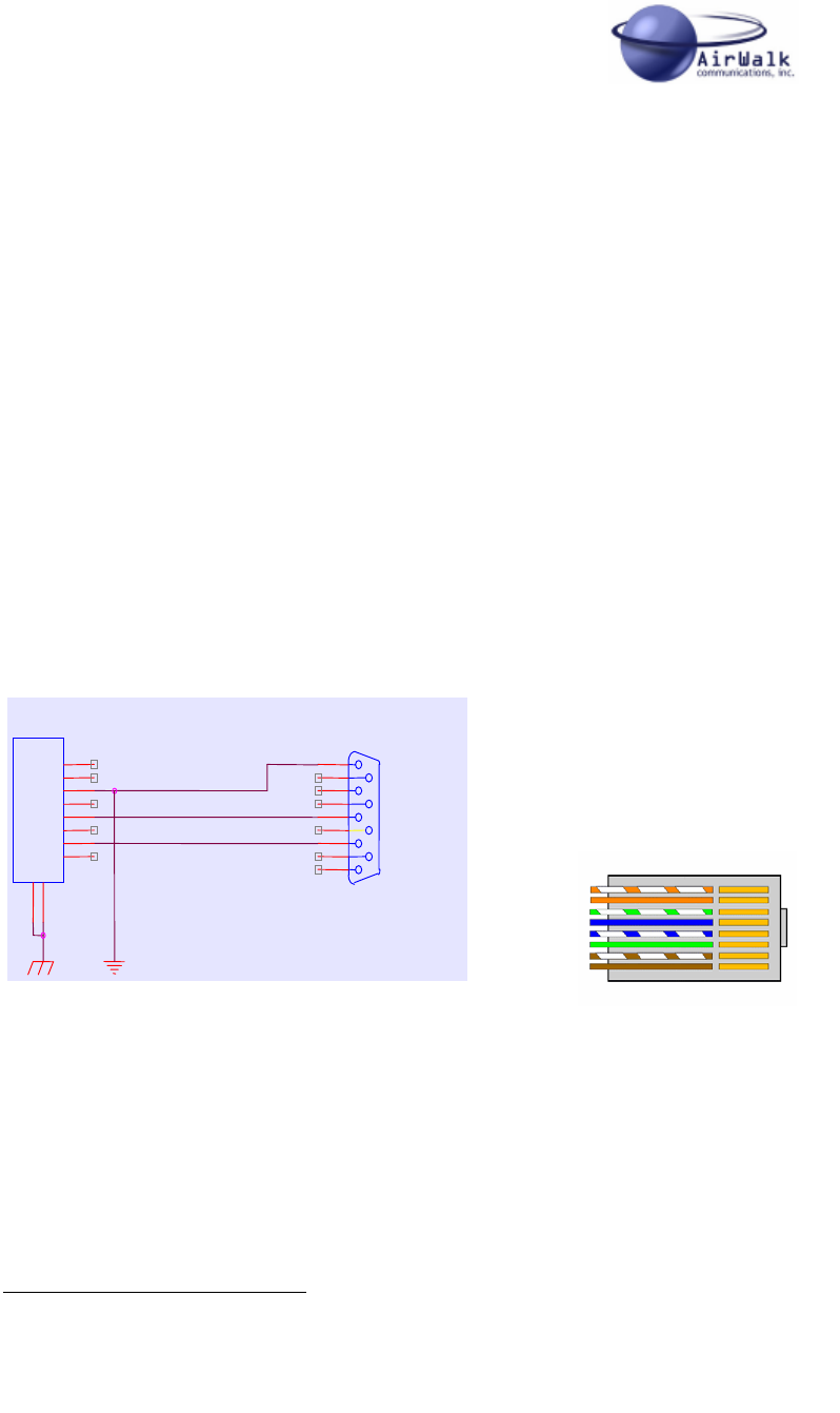
AW 96 Series System Installation Manual
___________________________________________________________________________
AirWalk Proprietary and Confidential Page 50 of 72 6/14/2006
10.2.6 Power-up procedure67
10.2.6.1 Power-up Main cabinet.
Make sure all appropriate LED’s are illuminated.
10.2.6.2 Complete any Configuration options.
a) Configure the AW-SERIES IP-RAN.
i) Outgoing and incoming channels.
10.3 System Test
This section contains the system tests that should be completed to determine if AW-
SERIES IP-RAN is operational.
10.3.1 PC to AW 96 cable
A special cable is required to run the required certification tests.
Connect a PC with the subject cable to run tests
BTS
P1
CONNECTOR DB9
5
9
4
8
3
7
2
6
1
RJ1
RJ-45
1
2
3
4
5
6
7
8
9
10
1
2
3
4
5
6
7
8
9
10
BTS
P1
CONNECTOR DB9
5
9
4
8
3
7
2
6
1
RJ1
RJ-45
1
2
3
4
5
6
7
8
9
10
1
2
3
4
5
6
7
8
9
10
Pin Configuration
DB9 RJ-45
(Computer) (BTS)
5 3
3 5
2 7
Figure 7-1 - PC to AW 96 Cable Specifiaction
6 Note: Once all connections are made, make sure to: Reset/install all breakers/fuses for
all main and intermediate breaker/fuse box(s). Then proceed with the Installation.
7 Make sure all added cabling is tie-wrapped correctly
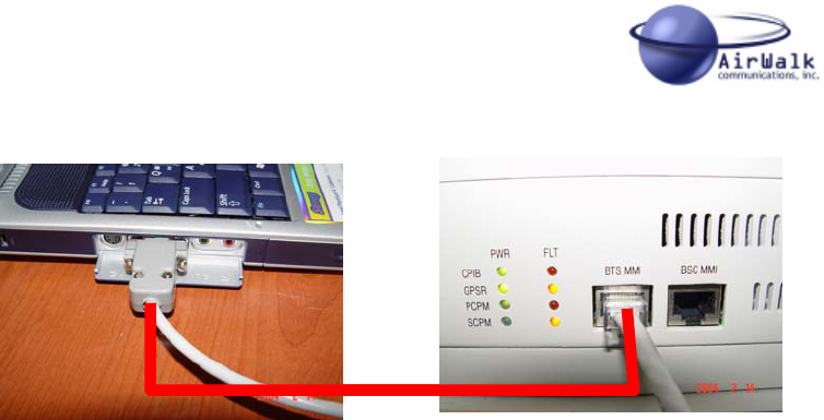
AW 96 Series System Installation Manual
___________________________________________________________________________
AirWalk Proprietary and Confidential Page 51 of 72 6/14/2006
Figure 7-2 - PC to AW 96 Cable Connection Diagram
10.3.2 System Certification Tests
Start The AW-SERIES IP-RAN tests.
This sequence of test cases is designed to certify the AW 96 IP-RAN installation.
It is assumed the person running this checklist is familiar with the basics of configuring,
running, stopping, and starting the AW 96 IP-RAN.
10.3.2.1 Test Case #1 - Image/PLD loading
10.3.2.1.1 Test Procedure #1
• Command: user: ipbs001
FTP password: ipbs001
• Command: Edit:
- P: display
- C: edit
10.3.2.1.2 Expected Result of Case #1
Screen from PC using ftp Server is shown in Figure 7-3.
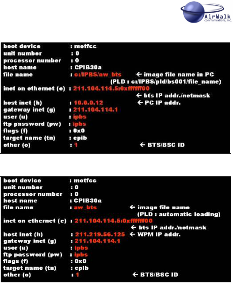
AW 96 Series System Installation Manual
___________________________________________________________________________
AirWalk Proprietary and Confidential Page 52 of 72 6/14/2006
Figure 7-3 - Screen from PC Screen from WPM
Figure 7-4 - Screen from PC
10.3.2.2 Test Case #2 – System Check
10.3.2.2.1 Test Procedure #2
• Command: Version
10.3.2.2.2 Expected Result of Case #2

AW 96 Series System Installation Manual
___________________________________________________________________________
AirWalk Proprietary and Confidential Page 53 of 72 6/14/2006
Figure 7-5 - Version Command Screen
10.3.2.3 Test Case #3 – Tx check
10.3.2.3.1 Test Procedure #3
• Command: txReason
• Expected Result of Case #3
Figure 7-6 - Tx Check Screen
10.3.2.4 Test Case #4 – Output power
10.3.2.4.1 Test Procedure #4 – RF Check
• Command: showRfGain
10.3.2.4.2 Expected Result of Case #4

AW 96 Series System Installation Manual
___________________________________________________________________________
AirWalk Proprietary and Confidential Page 54 of 72 6/14/2006
Figure 7-7 - RF Check Screen
10.3.2.5 Test Case #5 – GPS Check
10.3.2.5.1 Test Procedure #5
• Command: gpsStatus
10.3.2.5.2 Expected Result of Case #5
Figure 10-8 – GPS Status Check Screen
Figure 10-9 - GPS Alarm Check Screen
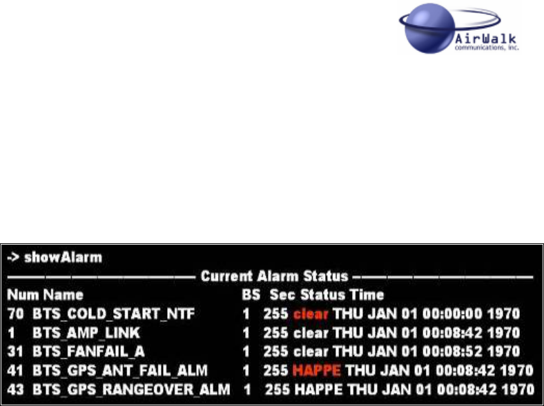
AW 96 Series System Installation Manual
___________________________________________________________________________
AirWalk Proprietary and Confidential Page 55 of 72 6/14/2006
10.3.2.6 Test Case #6 – BTS Alarm Check
10.3.2.6.1 Test Procedure #6
• Command: showAlarm
10.3.2.6.2 Expected Result of Case #6
Figure 10-10 - BTS Alarm Check Screen
10.3.2.7 Test Case #7 – System Reset
10.3.2.7.1 Test Procedure #7
• Command: btsReset/bscReset/allReset
10.3.2.7.2 Expected Result of Case #7
The system is RESET
10.3.2.8 Test Case #8 – PN Check
10.3.2.8.1 Test Procedure #8
• Command: RcmCmd 1,1
10.3.2.8.2 Expected Result of Case #8
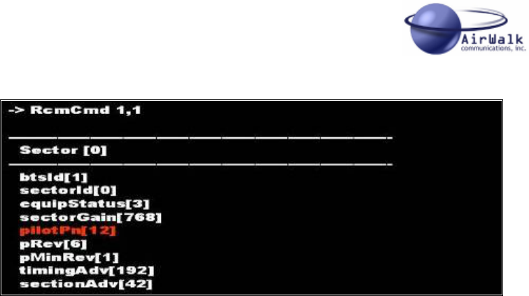
AW 96 Series System Installation Manual
___________________________________________________________________________
AirWalk Proprietary and Confidential Page 56 of 72 6/14/2006
Figure 10-11 - PN Check Screen
10.3.2.9 Test Case #9 – System Interface Check
10.3.2.9.1 Test Procedure
• Command: Ping
Send Ping Command to the Following system IP Addresses
1. WPM (Wireless PBX Manager)
2. PDSN (Packet Data Serving Node)
3. CA (Call Agent)
4. MG (Media Gateway)
5. SG (Signal Gateway)
10.3.2.9.2 Expected Result of Case #X
A successful PING command response from each system.
10.3.3 Operation Tests
These test cases are designed to determine if AW 96 is ready for production testing.
10.3.3.1 Test Case #1 – Voice Calls
10.3.3.1.1 Test Procedure
Test Call From MS #1 to MS #2.
Test Call From MS #1 to Landline Phone #1.
10.3.3.1.2 Excepted Result of Case #1
1. 2nd MS Rings and call is answered

AW 96 Series System Installation Manual
___________________________________________________________________________
AirWalk Proprietary and Confidential Page 57 of 72 6/14/2006
2. Landline phone Rings and call is answered.
10.3.3.2 Test Case #2 – Data Calls
10.3.3.2.1 Test Procedure
1. A Test Data Call From MS #1 to MS #2.
2. A Test Data Call From MS #2 to MS #1.
10.3.3.2.2 Excepted Result of Case #2
1. A Data Session is established between MS #1 and MS #2.
2. A Data Session is established between MS #2 and MS #1.
10.3.4 Operator Specific Tests
These test cases are covered in a separate test plan document and are agreed to by the
operator and AirWalk Communications, Inc.
10.4 Site Clean up and Customer Signoff
10.4.1 Dispose of all packing material.
Make sure to dispose of all AW-SERIES IP-RAN packing material.
10.4.2 Clean-up site.
Make sure not to leave anything but the installed AW-SERIES IP-RAN. (e.g., excess tie-
wraps, bolts, etc).
10.4.3 Update Installation Checklist.
Make sure all changes are notes on Installation Checklist.
10.4.4 Customer Signoff.
Get Customer Signature on Certification Document Appendix D.
10.5 Required Tools and Supplies
1) Hand Tools
a) Screwdriver set,
b) Pliers set,
c) Nut Driver set,
d) Cutter set,
e) Punch Down Tool,
f) Wire-wrap (Optional),
g) RJ-45 Crimper.

AW 96 Series System Installation Manual
___________________________________________________________________________
AirWalk Proprietary and Confidential Page 58 of 72 6/14/2006
2) Test Equipment.
a) Multi-Meter & Adapter kit,
b) Cable Tester,
c) Protocol Analyzer & Adapter kit,
d) Telephone Test Set (Butt-set),
e) Set of Banjo adapters
f) Tone Generator & Inductive pick-up.
3) Supplies.
a) RJ-45,
b) Cat 5 Cable,
c) Tie-wraps.
10.6 Troubleshooting Procedures
The AW-SERIES IP-RAN is designed to provide reliability and consistently high
performance in all network environments. The installation procedure for the AW-SERIES
IP-RAN is a straightforward and is discussed in these sections.
Should problems develop during installation, this section is intended to help locate,
identify and correct these types of problems. Please follow the suggestions listed below
prior to contacting AirWalk Communications, Inc. or Carrier contacts. If you are unsure of
the procedures described in this section, contact the Installation coordinator immediately.
10.6.1 Before Calling for Assistance
1) If difficulty is encountered with a specific component of the AW-SERIES IP-RAN,
refer back to the Installation Section for that component.
2) Check the cables and connectors to ensure that they have been properly connected
and the cables/wires have not been crimped or impaired in some way during
installation. (About 90% of component problems can be attributed to wiring and
connector problems).
a) Check Cable,
b) Check connector,
c) Check for solid connection,
d) Check with Carrier contact.
3) Make sure that all power cord is properly attached to each AW-SERIES IP-RAN
component. Be certain that all power cords are plugged into a functioning electrical
outlet. Use the PWR LED’s to verify each unit is receiving power.
a) Check intermediate breakers or fuses.
4) If the problem is isolated to something other than the AW-SERIES IP-RAN contact
the appropriate Carrier contact.

AW 96 Series System Installation Manual
___________________________________________________________________________
AirWalk Proprietary and Confidential Page 59 of 72 6/14/2006
5) Verify whether or not the problem is corrected. If not, go to Step 6 below. If the
problem is corrected, continue with installation.
6) If the problem continues after completing Step 4 above, contact the AirWalk
Communications, Inc. Installation Project manager, to determine the next course of
action.
10.6.2 When Calling for Assistance
Please be prepared to provide the following information.
1) A complete description of the problem, including the following points:
a) The nature and duration of the problem;
b) Situations when the problem occurs;
c) The components involved in the problem;
d) Any particular application that, when used, appears to create the problem;
2) A record of changes that have been made to the AW-SERIES IP-RAN configuration
prior to the occurrence of the problem.
3) Any changes to system should all be noted.

AW 96 Series System Installation Manual
___________________________________________________________________________
AirWalk Proprietary and Confidential Page 60 of 72 6/14/2006
11 Appendix A - Acronyms
Acronym Description
2G Second Generation in CDMA wireless network
3G Third Generation in CDMA wireless network
AC Alternating Current
Access
Channel
A Reverse CDMA Channel used by mobile stations for communicating to the
base station. The Access Channel is used for short signaling message
exchanges, such as call originations, responses to pages and registrations. The
Access Channel is a slotted random access channel.
ACH Access Channel
AD Analog to Digital
AFEU Antenna Front End Unit
AGC Automatic Gain Control
ANT Antenna
AWGN Additive White Gaussian Noise
Base Station
(BS)
A fixed station used for communicating with mobile stations. Depending upon
the context, the term base station may refer to a cell, a sector within a cell, an
MSC, or other part of the wireless system.
BCCM BTS Call Control Module
BHCA Busy Hour Call Attempts
BLK Blank
BS Base Station
BSAP Base Station Application Part
BSC Base Station Controller
BSMAP Base Station Management Application Part
BTS Base station Transceiver Subsystem
CA Call Agent
CAI Common Air Interface
CC Connection Confirm
CCM Channel Control Module in BTS
CDMA Code Division Multiple Access
CEC Channel Elements Control Block
CED Channel Elements Diagnostic Block
CLAP Composite Link Analysis Platform
CPIB BTS Channel and Call Processing Interface Board
CPU Central Processing Unit
CR Connection Request
CREF Connection Refused
CSM5000 Cell Site Modulator 5000 (CDMA ASIC chip released by Qualcomm for
cdma2000)
DA Digital to Analog
DC Direct Current
DCCH Dedicated Control Channel
DCLI Data Link Connection Identifier
DRS Data Ready to Send
DT Data Form

AW 96 Series System Installation Manual
___________________________________________________________________________
AirWalk Proprietary and Confidential Page 61 of 72 6/14/2006
Acronym Description
DTAP Direct Transfer Application Part
EMI Electro-Magnetic Interference
ESN Electronic Serial Number
EVDO Evolution Data Only
EVDV Evolution Data and Voice
EVRC Enhanced Variable Rate CODEC
FA Frequency Assignment
FCC Federal Communications Commission
F-CCH Forward Common Control Channel
FCH Fundamental Channel
F-DCCH Forward Dedicated Control Channel
FDCH Forward Dedicated Signaling Logical Channel
FER Frame Error Rate
FM Fault Management
FO Frame Offset
Forward
Traffic
Channel
One or more code channels used to transport user and signaling traffic from the
base station to the mobile station.
FSCH Forward Common Signaling Logical Channel
GND Ground
GPS Global Positioning System
GRE Generic Routing Encapsulation
HLR Home Location Register
HO Handoff
HPAU High Power Amplifier Unit
IF Intermediate Frequency
IMSI International Mobile Subscriber Identity
ING Inter Network Gateway
IOS Interoperability System
IP Internet Protocol
IPC Inter Processor Communication
LAC Link Access Control.
Entity that provides assured mode or unassured mode delivery of information
across the air interface between the mobile station and the base station.
LPA Linear Power Amplifier
LTU Logical Transmission Unit
One or more Type 3 or Type 5 MuxPDUs with a 16bit CRC.
MAC Medium Access Control
Entity that controls the access to and from Upper Layer Signaling, Data Services
and Voice Services to Physical Layer resources.
MAHHO Mobile Assisted Hard Hand Off
MCC Main Call Control module in IP-BSC
MG Media Gateway
MIMO Multi Input Multi Output
MIN Mobile Identification Number
MMC Man-Machine Command
MMS Multimedia Messaging Service
MN Mobile Node

AW 96 Series System Installation Manual
___________________________________________________________________________
AirWalk Proprietary and Confidential Page 62 of 72 6/14/2006
Acronym Description
MS Mobile Station
MSC Mobile Switching Center
MTBF Mean Time between Failure
MTTR Mean Time to Repair
NDSS Network Directed System Selection
NGN Next Generation Networks
NMS Network Management System
OAM Operation, Administration, and Maintenance
OCNS Orthogonal channel Noise Simulator
OS Operating System
OTD Orthogonal Transmit Diversity
OUNS Other User Noise Source
PACA Priority Access Channel Assignment
Paging
Channel
A code channel in a Forward CDMA Channel used for transmission of control
information and pages from a base station to a mobile station
PBA Printed Board Assembly
PBX Private Branch Exchange
PCB Printed Circuit Board
PCF Packet Control Function in IP-BSC
PCH Paging Channel
PCM Pulse Code Modulation
PCPM Primary BSC Call Processing Board
PDSN Packet Data Serving Node
PDU Protocol Data Unit. An atomic set of data, header information, and control
information that are provided by a service user to a service provider.
PER Packet Error Rate
Physical
Channel
Radio transmission link
Pilot
Channel
An un-modulated, direct-sequence spread spectrum signal transmitted by a
CDMA base station or mobile station. A pilot channel provides a phase
reference for coherent demodulation and may provide a means for signal
strength comparisons between base stations for determining when to handoff.
PLD Program Loaded Data
PN Pseudo Noise
PSA Power Supply Assembly
PSTN Public Switched Telephone Network
QCELP Qualcomm Code Excited Linear Prediction
QOF Quasi-Orthogonal Function
QOF Quasi Orthogonal Function
QoS Quality of Service
RAN Radio Access network
RC Radio Configuration
RCC Radio interface Call Control
RDCH Reverse Dedicated Signaling Logical Channel
Reverse
Traffic
Channel
A traffic channel on which data and signaling are transmitted from a mobile
station to a base station. The Reverse Traffic Channel is composed of up to one
Reverse Dedicated Control Channel, up to one Reverse Fundamental Channel,
zero to two Reverse Supplemental Channels, and zero to seven Reverse

AW 96 Series System Installation Manual
___________________________________________________________________________
AirWalk Proprietary and Confidential Page 63 of 72 6/14/2006
Acronym Description
Supplemental Code Channels.
RF Radio Frequency
RLC Release Complete
RLP Radio Link Protocol. Connection-oriented, negative-acknowledgement-based
data delivery protocol.
RLSD Released
RP Radio Network – PDSN
RPSU Remote RF Power Supply Unit
RRCU Remote RF Control Unit
RRM Radio Resource Management Block
RRP Registration Reply Message
RRQ Registration Request Message
RSCH Reverse Common Signaling Logical Channel
RSSI Received Signal Strength Indication
RTP Real-Time Transport Protocol
RU Remote RF Unit
RUpd Registration Update Message
SAP Service Access Point
Conceptual point at the interface between two adjacent layers where services
are provided to the upper layer and data and protocol information is exchanged
between layers.
SAR Segmentation and Reassembly
SCCH Supplemental Code Channel
SCCP Signaling Connection Control Protocol
SCH Supplemental Channel
SDU Selection and Distribution Unit
SEU Sector Expansion Unit
SIGTRAN Signaling Transport processing module in IP-BSC
Slotted Mode An operation mode of the mobile station in which the mobile station monitors
only selected slots on the Paging Channel
SMS Short Message Service
SMV Selectable Mode VOCODER
SRBP Signaling Radio Burst Protocol. An entity that provides connectionless protocol
for Signaling messages.
SRU Sector Reduction Unit
SS Soft Switch
STS Space Time Spreading
Sync
Channel
A code channel in the Forward CDMA Channel which transports the
synchronization message to the mobile station
TCC Traffic Channel Control Block
TCE Traffic Channel Element
TCM Traffic Control Module in BTS
TCP Transmission Control Protocol
TOD Time of Day
TP Traffic processing and Path Control module in IP-BSC
TPTL Transmit Power Tracking Loop
UART Universal Asynchronous Receiver/Transmitter
UDP User Datagram Protocol

AW 96 Series System Installation Manual
___________________________________________________________________________
AirWalk Proprietary and Confidential Page 64 of 72 6/14/2006
Acronym Description
VSWR Voltage Standing Wave Ratio
XCV Base Station Transceiver Control Block
XCVR Transceiver Board

AW2100U System Installation Manual
__________________________________________________________________________________________________________________
AirWalk Proprietary and Confidential Page 65 of 72 6/14/2006
12 Appendix B - Site preparation checklist
AW-Series IP-RAN Site Preparation Check List for: {Customer Name}
ITEM # Description
Site
Prep
Guide
Section
#
Date
Complete Com
plete Information
1 Customer Contact & Equipment location 1
a. Main Contact Customer 1.1.1
b. Other Customer Contacts 1.1.2
1. Power contact 1.1.2
2. Communications Facilities Contact 1.1.2
3. LAN Facilities Contact 1.1.2
4. MSC Security Contact 1.1.2
c. Complete Customer Questions Appendix C App. C
2 AirWalk Series IP-RAN Site Requirements 2.1
a. Space requirements 2.1.1
b. AirWalk Series IP-RAN placement Diagram 2.1.2
c. Installation Location for AirWalk Series IP-RAN Equipment 2.1.2.1
3 Complete Site Drawings Appendix B App. B

AW2100U System Installation Manual
__________________________________________________________________________________________________________________
AirWalk Proprietary and Confidential Page 66 of 72 6/14/2006
ITEM # Description
Site
Prep
Guide
Section
#
Date
Complete Com
plete Information
Power requirements 2.1.3
a. Location
b. Voltage
c. Amps
d. Connector
Security 2.1.3
a. MSC Equipment Room security
b. MSC Equipment room access
Communications Facilities 2.1.3
a. Number of T1 circuits
Connector
Location
LAN Facilities 2.1.3
a. Location
b. Connector
c. Carrier Network IP Address
d. AirWalk Series IP-RAN Component IP Addresses
Other Information

AW2100U System Installation Manual
__________________________________________________________________________________________________________________
AirWalk Proprietary and Confidential Page 67 of 72 6/14/2006
ITEM # Description
Site
Prep
Guide
Section
#
Date
Complete Com
plete Information
a. Heat dissipation
b. Environmental specifications 2.1.4
c. Ambient temperature and humidity 2.1.4.2
d. Dust density 2.1.4.4
e. Altitude 2.1.4.5
f. Air conditioning 2.1.4.6
g. Fire protection
AW2100U System Installation Manual
____________________________________________________________________________________________________________________
AirWalk Proprietary and Confidential Page 68 of 72 6/14/2006
13 Appendix C - Installation Checklist
AW-Series IP-RAN Site Installation Check List for: {Customer Name}
Address Installer Name (s) Customer Contact (s)
{AW-SERIES IP-RAN Installation Address}
ITEM
# Description Install
Manual
Section
Date
Complete
Time Customer
Contact
Initials
Installer
Initials
1 Verify Customer Contact & Equipment location 9.1.1
2 Contact Customer 9.1.1.1
3 Locate AW-SERIES IP-RAN Equipment 9.1.1.2
4 Locate and verify Floor Space 9.1.1.3
5 Uncrate and arrange for packing material disposal 9.1.2
6 Verify location of all distribution points (main and intermediate) 9.1.3
7 Power Check 9.1.3.1
8 Power Location 9.1.3.1.1
9 Verify Connector 9.1.3.1.2
10 Voltage 9.1.3.1.3
11 Amps 9.1.3.1.4
12 LAN Facilities check 9.1.3.1.5
13 Location 9.1.5.1.5
14 Verify IP Address 9.1.3.1.5
15 Verify Connector 9.1.3.1.5
16 Ping IP Address 9.1.3.1.5

AW2100U System Installation Manual
____________________________________________________________________________________________________________________
AirWalk Proprietary and Confidential Page 69 of 72 6/14/2006
ITEM
# Description Install
Manual
Section
Date
Complete
Time Customer
Contact
Initials
Installer
Initials
17 Prepare IP addressable device diagram 9.1.3.1.5
18 Post IP diagram at: i) site; ii) customer; iii) Airwalk Customer Service 9.1.3.1.5
19 Install AW-SERIES IP-RAN Cabinet 9.2.1
20 Move AW-SERIES IP-RAN to location 9.2.1
21 Secure AW-SERIES IP-RAN in designated location 9.2.1
22 Verify all internal System connections 9.2.2
23 External System Connections 9.2.3
MAKE SURE ALL SYSTEM POWER SUPPLIES ARE TURNED OFF BEFORE PROCEEDING! ! !
24 Connect Power to Cabinet 9.2.4
25 Connect -48VDC to DC distribution panel (If applicable) 9.2.4
26 Connect 120-240 VAC to AC distribution panel (If applicable) 9.2.4
27 Connect Communications Facilities 9.2.5
28 Connect LAN Facilities to BSC 9.2.5
29 Connect LAN Facilities to BTS 9.2.5
30 Power-up procedure 9.2.6
31 Power-up Main cabinet/rack power, check LEDs 9.2.6.1
32 Complete any configuration options 9.2.6.2
System Certification Tests 9.3.2
33 Test Case #1 - Image/PLD loading 9.3.2.1
34 Test Case #2 – System Check 9.3.2.2
35 Test Case #3 – Tx check 9.3.2.3
36 Test Case #4 – Output power 9.3.2.4
37 Test Case #5 – GPS Check 9.3.2.5
38 Test Case #6 – BTS Alarm Check 9.3.2.6
39 Test Case #7 – System Reset 9.3.2.7
40 Test Case #8 – PN Check 9.3.2.8

AW2100U System Installation Manual
____________________________________________________________________________________________________________________
AirWalk Proprietary and Confidential Page 70 of 72 6/14/2006
ITEM
# Description Install
Manual
Section
Date
Complete
Time Customer
Contact
Initials
Installer
Initials
41 Test Case #9 – System Interface Check 9.3.2.9
Operation Tests 9.3.3
42 Test Case #1 – Voice Calls 9.3.3.1
43 Test Case #2 – Data Calls 9.3.3.2
44 Operator Specific Tests (If Required) 10.3.4
Site Clean Up & Documentation
45 Dispose of all packing material 10.4.1
46 Clean-up site 10.4.2
47 Update Installation Checklist 10.4.3
48 Get Customer Signature on Certification Document 10.4.4

AW2100U System Installation Manual
___________________________________________________________________________
AirWalk Proprietary and Confidential Page 71 of 72 6/14/2006
14 Appendix D - Customer Certification Document
Date
Subject:
The subject AW-SERIES IP-RAN has been certified to be up and running today.
_______________________________________ __________________
AirWalk Communications, Inc. (Installation Team) Date
_______________________________________ __________________
Authorized Carrier Representative Date

AW2100U System Installation Manual
___________________________________________________________________________
AirWalk Proprietary and Confidential Page 72 of 72 6/14/2006
This Page Marks End Of Document