AirWalk Communications AWFTRBU1 AW100 1900MHz 0.1mW User Manual
AirWalk Communications, Inc. AW100 1900MHz 0.1mW
User Manual

_____________________________________________________________________________
AirWalk Proprietary and Confidential Page 1 of 54
AW100 Series
CDMA2000 1xRTT and 1xEV-DO
IP Radio Access Network (IP-RAN)
Installation and Maintenance Manual
Version # 0.4
April, 2010
Prepared By
AirWalk Communications, Inc.
1830 North Greenville Ave
Richardson, TX, 75081
Phone: (972) 638-9400
Fax: (972) 638-9401
www.airwalkcom.com
FOR USE BY TRAINED TECHNICIANS ONLY
AW100 Series System Installation Manual
____________________________________________________________________________
_____________________________________________________________________________
AirWalk Proprietary and Confidential Page 2 of 54
Revision History
Version Date Person Description
0.1 07/24/2009 R MacLennan Initial Draft Document for review
0.2 10/07/2009 N. Kafai Addition on Introduction
0.3 12/2/12009 N. Kafai Edited Specifications
0.4 4/7/2010 A Cho Edited Technical Specs
Revision Numbering Key
0.x Work in Progress
1.0 Initial Document Approval
1.x Revisions Following Initial Document Approval
2.0 Revisions Approval

AW100 Series System Installation Manual
____________________________________________________________________________
_____________________________________________________________________________
AirWalk Proprietary and Confidential Page 3 of 54
Table of Contents
TABLE OF CONTENTS .................................................................................................................................. 3
1INTRODUCTION ..................................................................................................................................... 5
1.1PROPRIETARY INFORMATION NOTICE .................................................................................................. 5
1.2PURPOSE OF DOCUMENT ...................................................................................................................... 5
1.3SCOPE .................................................................................................................................................. 5
1.4ORDER OF PRECEDENCE ....................................................................................................................... 5
1.5TERMINOLOGY ..................................................................................................................................... 5
1.6TELECOM STANDARDS ......................................................................................................................... 6
2AW100 SAFETY AND COMPLIANCE INFORMATION .................................................................. 8
2.1STATEMENT OF INTENT ........................................................................................................................ 8
2.2SAFETY PRECAUTIONS ......................................................................................................................... 8
2.3MAINTENANCE INFORMATION ............................................................................................................. 9
2.3.1Cleaning ...................................................................................................................................... 9
2.3.2Other Maintenance ...................................................................................................................... 9
2.4LABELING ............................................................................................................................................ 9
2.4.1Grounding ................................................................................................................................... 9
2.4.2Label: Model Identification, FCC Identification, Power ............................................................ 9
2.5REGULATORY COMPLIANCE INFORMATION ....................................................................................... 10
2.5.1Radio Interference (FCC 15.19 Statement) ............................................................................... 10
2.5.2Unauthorized Modifications (FCC 15.21 Statement) ................................................................ 10
2.5.3Digital Device Interference (FCC 15.105 Statement) ............................................................... 10
2.5.4RF Power Requirements ............................................................................................................ 10
3AW100 SYSTEM INTRODUCTION .................................................................................................... 11
3.1OVERVIEW ......................................................................................................................................... 11
3.2AW100 NETWORK DIAGRAM ............................................................................................................ 13
3.3HARDWARE CONFIGURATION ............................................................................................................ 15
3.3.1Physical Description ................................................................................................................. 15
3.3.2Typical Configurations .............................................................................................................. 15
3.3.3Unit Photographs ...................................................................................................................... 16
3.4SYSTEM CAPACITIES AND SPECIFICATIONS ........................................................................................ 17
3.4.1AW-100 Technical Specifications .............................................................................................. 17
3.4.2Radio Unit Technical Specification (Slim RU Series) ............................................................... 18
3.4.3Power Supply and Environment Technical Specification .......................................................... 19
4AW-100 COMPONENTS ....................................................................................................................... 20
4.1AW-100 MAIN UNIT .......................................................................................................................... 20
4.2RADIO UNIT (RU - SLIM RU SERIES) ................................................................................................. 21
4.3OPTIONAL DC RPSU (DC POWER CONFIGURATIONS ONLY) ............................................................. 22
4.4COMPONENT LED CONFIGURATION .................................................................................................. 23
4.4.1CCPB- (Call and Channel Processing Board) .......................................................................... 23
4.4.2RU DC Power Distribution Unit (RPSU) [DC powered models only] ..................................... 24
4.4.3Radio Units Front Panel Indicators (Slim RU Series) .............................................................. 25
5AW-100 CABLING ................................................................................................................................. 26
5.1POWER SUPPLY WIRING (AC / DC POWERED VERSIONS) .................................................................. 26
5.2GROUNDING ....................................................................................................................................... 26
5.3RF CABLING WITH RU ....................................................................................................................... 27

AW100 Series System Installation Manual
____________________________________________________________________________
_____________________________________________________________________________
AirWalk Proprietary and Confidential Page 4 of 54
5.4POWER SUPPLY WIRING (DC POWERED MODELS) ............................................................................. 28
5.5GPS ANTENNA CABLE WIRING .......................................................................................................... 30
6FREQUENCY SETTING PROCEDURES .......................................................................................... 31
6.1IBSM MANAGEMENT ......................................................................................................................... 31
6.2LOCAL FA SETTING ........................................................................................................................... 31
6.2.1MMI Connection ....................................................................................................................... 31
6.2.2FA Change Procedure ............................................................................................................... 32
7INSTALLATION PROCEDURES ........................................................................................................ 37
7.1VERIFY CUSTOMER CONTACT AND EQUIPMENT LOCATION ............................................................... 37
7.1.1Contact customer ....................................................................................................................... 37
7.1.2Locate and verify floor space .................................................................................................... 38
7.1.3Uncrate and arrange for packing material disposal ................................................................. 38
7.1.4Verify location of power distribution points .............................................................................. 38
7.1.5Verify location of LAN facilities and connection points ............................................................ 39
7.1.6Verify location of RF Antenna Systems, including GPS ............................................................ 39
7.1.7Verify physical mounting racks are present and suitable .......................................................... 40
7.2IP-RAN INSTALLATION PROCEDURES ............................................................................................... 41
7.2.1IP-RAN System physical installation ......................................................................................... 41
7.2.2Internal system cable connections ............................................................................................. 41
7.2.3External system Connections ..................................................................................................... 41
7.2.4Power-up procedure .................................................................................................................. 42
7.2.5Installation Completion ............................................................................................................. 43
7.3INITIAL SYSTEM CONFIGURATION ...................................................................................................... 43
7.3.1Web Server Installation Tool Set-up .......................................................................................... 44
7.3.2Web Server Connections ........................................................................................................... 44
7.3.3IP-RAN Initial Configuration (default “booting mode”) .......................................................... 46
7.3.4IP-RAN Re-Configuration (“running mode”) ........................................................................... 47
7.3.5Additional Operation Tests ....................................................................................................... 48
7.4SITE CLEANUP AND CUSTOMER SIGNOFF ........................................................................................... 48
7.5RECOMMENDED INSTALLATION TOOLS AND SUPPLIES ...................................................................... 49
7.6TROUBLESHOOTING PROCEDURES ..................................................................................................... 49
7.6.1Before Calling for Assistance .................................................................................................... 49
7.6.2When Calling for Assistance ..................................................................................................... 50
8APPENDIX A - ACRONYMS ................................................................................................................ 51
9APPENDIX B - INSTALLATION CERTIFICATION DOCUMENT ............................................... 53

AW100 Series System Installation Manual
____________________________________________________________________________
_____________________________________________________________________________
AirWalk Proprietary and Confidential Page 5 of 54
1 INTRODUCTION
1.1 Proprietary Information Notice
THIS DOCUMENT IS THE PROPERTY OF AIRWALK COMMUNICATIONS, INC. THE
RECIPIENT MAY USE IT ONLY FOR THE PURPOSE FOR WHICH IT WAS
TRANSMITTED AND WILL BE RETURNED UPON REQUEST OR WHEN NO LONGER
NEEDED BY RECIPIENT. IT MAY NOT BE COPIED OR COMMUNICATED WITHOUT
THE WRITTEN CONSENT OF AIRWALK COMMUNICATIONS, INC.
1.2 Purpose of Document
The purpose of this document is to define the Installation, Maintenance and Safety
Compliance of AirWalk Communications, Inc. unique CDMA IP Radio Access Network
(IP- RAN), referred to herein as the AW100 product.
The AirWalk AW100 series is available in two separate platforms:
• AW100-1X which support CDMA - 1xRTT standard, which includes integrated
Base Station Transceiver (BTS) and Base Station Controller (BSC) into a unique
single compact enclosure.
• AW100-DO which supports CDMA - 1xEVDO Rev. A standard which includes
integrated Radio Node (RN) and Radio Network Controller (RNC) into a unique
single compact enclosure.
The target market and applications are in-building areas, corporations, corporate
campuses, enterprises, university campuses, large industrial plants, stadiums, airports,
shopping malls, blind spots, hot spots, rural areas, neighborhoods, and highways.
1.3 Scope
The scope of this document covers the description, environmental specifications,
equipment location, cabling, system installation and maintenance of the AirWalk AW-100.
Specific models covered are identified in the section entitled “Model Information”.
1.4 Order of Precedence
This System Installation Manual will take precedence over any previous AirWalk System
Installation Manual or Document.
1.5 Terminology
See the section entitled: Appendix A – Acronyms

AW100 Series System Installation Manual
____________________________________________________________________________
_____________________________________________________________________________
AirWalk Proprietary and Confidential Page 6 of 54
1.6 Telecom Standards
[1] 3GPP2 C.S0001 – 0006 Radio Interface Specifications for cdma2000 Spread Spectrum
System
[2] 3GPP2 X.S0013 – IMS/MMD Specifications
[3] 3GPP2 A.S0013-C Interoperability Specification (IOS) for cdma2000 Access Network
Interfaces – Part 3 Features
[4] 3GPP2 A.S0014-C Interoperability Specification (IOS) for cdma2000 Access Network
Interfaces – Part 4 (A1, A1p, A2 and A5 Interfaces)
[5] 3GPP2 C.S0015 Short Message Service
[6] RFC 3261 – Session Initiation Protocol
[7] RFC 4566 – SDP: Session Description Protocol
[8] RFC 3455 – Private Header (P-Header) Extensions to the Session Initiation Protocol for the
3rd-Generation Partnership Project (3GPP)
[9] RFC 3325 – Private Extensions to the Session Initiation Protocol for Asserted Identity within
Trusted Networks
[10] RFC 3262 – Reliability of Provisional Responses in Session Initiation Protocol
[11] RFC 3311 – The Session Initiation Protocol UPDATE Method
[12] RFC 2976 – The SIP INFO Method
[13] RFC 4028 – Session Timers in the Session Initiation Protocol
[14] RFC 4306 – Internet Key Exchange (IKEv2) Protocol
[15] TIA/EIA/IS-2000 Series Revision: C - Introduction to CDMA2000 Spread Spectrum Systems,
05/00/02
[16] Personal Station – Base Station Compatibility Requirements for 1.8 to 2.0 GHz CDMA PCS.
[17] TIA/EIA-664 - Wireless Features Description, 12/00/00
[18] TIA/EIA Interim Standard 95 Revision A - Mobile Station –Base Station Compatibility
Standard for Dual-Mode Wideband Spread Spectrum Cellular Systems, May 1995
[19] TIA/EIA-95-B - Mobile Station-Base Station Compatibility Standard for Dual-Mode Spread
Spectrum Systems, October 31, 1998
[20] MSC to BS Interface Inter-Operability Specification (IOS) Sprint PCS IOS Document, v2.0a,
December 4, 1997
[21] IMT-2000 Specification, (indoor wireless propagation)
[22] RFC 3558 RTP Payload Format for Enhanced Variable Rate Codecs (EVRC) and Selectable
Mode Vocoders (SMV), July 2003
[23] RFC 2833 RTP Payload for DTMF Digits, Telephony Tones and Telephony Signals, May
2000
[24] 3GPP2 A.S0013-C Interoperability Specification (IOS) for cdma2000 Access Network
Interfaces – Part 1 Overview
[25] 3GPP2 A.S0013-C Interoperability Specification (IOS) for cdma2000 Access Network
Interfaces – Part 2 Transport
[26] 3GPP2 A.S0013-C Interoperability Specification (IOS) for cdma2000 Access Network
Interfaces – Part 7 (A10 and A11 Interfaces)
[27] 3GPP2 C.S0002-D, Physical Layer Standard for cdma2000 Spread Spectrum Systems,
March 2004
[28] 3GPP2 C.S0004-D, Signaling Link Access Control (LAC) Standard for cdma2000 Spread
Spectrum Systems, Feb. 2004

AW100 Series System Installation Manual
____________________________________________________________________________
_____________________________________________________________________________
AirWalk Proprietary and Confidential Page 7 of 54
[29] 3GPP2 C.20000.5-D, Upper Layer (Layer 3) Signaling Standard for cdma2000 Spread
Spectrum Systems, March 2004
[30] IS-707-A-2, Data Service Options for Spread Spectrum Systems, March 2001
[31] TIA/EIA/IS-856-A, cdma2000 High Rate Packet Data Air Interface Specification, Mar 2004
[32] C.R1001-D, Administration of Parameter Value Assignments for cdma2000 Spread Spectrum
Standards, Release B
[33] RFC 1661, Point-to-Point Protocol, July 1994
[34] RFC 1662, PPP in HDLC-Like Framing, July 1994
[35] RFC 1701, Generic Routing Encapsulation (GRE) Protocol, Oct 1994
[36] RFC 1994, PPP Challenge Handshake Authentication Protocol (CHAP), August 1996
[37] 3GPP2 A.S0008-0 v3.0 (TIA-878-1 pub), “Interoperability Specification (IOS) for High Rate
Packet Data (HRPD) Access Network Interfaces”, May 2003
[38] 3GPP2 A.S0007-A v2.0 (TIA-1878 pub), “Interoperability Specification (IOS) for High Rate
Packet Data (HRPD) Access Network Interfaces – Rev A”, May 2003
[39] 3GPP2 C.S0024-A v1.0 (TIA-856-A), “cdma2000 High Rate Packet Data Air Interface
Specification”, March 2004
[40] 3GPP2 C.S0032 v2.0, Recommended Minimum Performance Standards for cdma2000 High
Rate Packet Data Access Networks, Jan. 2004
[41] 3GPP2 X.S0011-001-C v3.0, cdma2000 Wireless IP Network Standard, Oct. 2006
AW100 Series System Installation Manual
____________________________________________________________________________
_____________________________________________________________________________
AirWalk Proprietary and Confidential Page 8 of 54
2 AW100 Safety and Compliance Information
2.1 Statement of Intent
The AirWalk AW100 Series IP-RAN is intended for use in a CDMA cellular infrastructure
radio access network. The responsible body shall be made aware that, if the equipment
is used in a manner not specified by the manufacturer, the protection provided by the
equipment may be impaired.
2.2 Safety Precautions
Power Sources
Use only power sources that are within the specified limits as designated on the
equipment labels. Use of power sources outside the specified limits is hazardous and
may cause personal injury or property damage.
Equipment Location
Equipment should be located indoors or in a suitable protected environment such as an
equipment enclosure. Use of unprotected equipment outdoors is hazardous and may
cause personal injury or property damage.
Grounding and Electrical Connections
Electrical connections, including equipment grounding, should be made in accordance
with the National Electric Code and any local regulations. Improper electrical connections
are hazardous and may cause personal injury or property damage. Consult a licensed
electrical installer if in doubt.
DC powered units MUST be externally fused for proper protection.
Hazardous Voltages
Equipment may contain hazardous voltages. Only qualified service personnel should
open the equipment for adjustments, repairs or replacements.
Replacement Parts
Damaged parts and protective devices such as fuses should only be replaced by
components approved or recommended by AirWalk Communications. Replacement
fuses must be of the same rating and type as the original for continued protection.
AW100 Series System Installation Manual
____________________________________________________________________________
_____________________________________________________________________________
AirWalk Proprietary and Confidential Page 9 of 54
2.3 Maintenance Information
2.3.1 Cleaning
The AirWalk AW100 units are protected by a high performance paint which does not
require normal maintenance. If paintwork is soiled, it can be cleaned using a damp cloth
after AC power has been disconnected. Do not use liquids or spray cleaning substances
on the unit, since property damage or personal injury may result.
2.3.2 Other Maintenance
Any other required maintenance must be performed by suitable trained service personnel.
Do not open covers or attempt to repair unit if not suitably trained.
2.4 Labeling
2.4.1 Grounding
Proper grounding is recommended to ensure good RF performance in addition to
personnel safety. Antenna systems should also be suitably grounded for good RF
performance.
Grounding connection points on the chassis are located on the rear of the unit and are
identified by this symbol:
2.4.2 Label: Model Identification, FCC Identification, Power
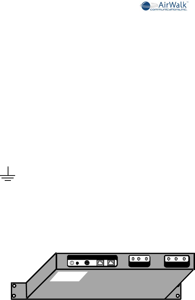
The following illustrates the location of the FCC label that will be applied to the AW100
unit to provide model identification, FCC identification and rated power supply information.
Some units are not equipped with FCC identification and therefore operation of these
units in the US is not permitted.
Figure 2-1 AW100 Main Unit (Bottom - Rear View)
PWR 12VDC RUIF BSIF
BSIF 10MEVENGPS
ANT
TRXRXARXB
Bottom Side o
f
Unit
FCC ID Label
Location
AW100 Series System Installation Manual
____________________________________________________________________________
_____________________________________________________________________________
AirWalk Proprietary and Confidential Page 10 of 54
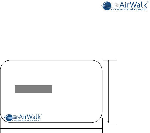
2.5 Regulatory Compliance Information
The FCC regulatory compliance information provided in this section is applicable only to
models equipped with an FCC Identification Number (FCC ID).
IP-RAN Base Station
Model : AW100xxxxxxx
FCC ID : R4Hxxxxxxxx
S/N :
76.0 mm
50.0 mm
DC IN: 12 VDC / 8A
AirWalk Communications., Inc Contact: +1-972-638-9400
XX0000X
Made In U.S.A.
Figure 2-2 AW-100 FCC Label (SAMPLE)
2.5.1 Radio Interference (FCC 15.19 Statement)
This device complies with part 15 of the FCC Rules. Operation is subject to the following
two conditions: (1) This device may not cause harmful interference, and (2) This device
must accept any interference received, including interference that may cause undesired
operation.
2.5.2 Unauthorized Modifications (FCC 15.21 Statement)
Persons or parties responsible for operation of this equipment are cautioned that any
changes or modifications not expressly approved by AirWalk Communications
Incorporated could void the user’s authority to operate this equipment.
2.5.3 Digital Device Interference (FCC 15.105 Statement)
This equipment has been tested and found to comply with the limits for a Class B digital
device, pursuant to part 15 of the FCC Rules. These limits are designed to provide
reasonable protection against harmful interference in a residential installation. This
equipment generates, uses, and can radiate radio frequency energy and, if not installed
and used in accordance with the instructions, may cause harmful interference to radio
communications.
2.5.4 RF Power Requirements
The antenna(s) used for this transmitter must be fixed-mounted on outdoor permanent
structures.

AW100 Series System Installation Manual
____________________________________________________________________________
_____________________________________________________________________________
AirWalk Proprietary and Confidential Page 11 of 54
3 AW100 System Introduction
3.1 Overview
This document describes the AW100 IP-RAN products developed by AirWalk
Communications Inc. The AirWalk AW100 Series is compact, standards compliant,
optimal channel capacity, cost effective, and reliable cellular access point designed to
provide improved mobile coverage and capacity enhancements for the CDMA mobile
operators.
The AW100 is offered in two different platforms:
• AW100-1X
• This product is designed specifically for CDMA2000 1xRTT networks. The
principal elements of the AW100-1X product are integrated BTS, BSC, and PCF
functionality with the capability to connect to the core network via:
• IOS 5.X for connectivity to CDMA soft switch networks
• IOS to SIP messages for connectivity to IMS networks
The following is a list of general characteristics:
• Supports both CDMA 1xRTT voice and data calls
• Supports 32CE and /or 64 CE (Up to 28 or 56 users)
• Supports CDMA 1xRTT data service transmission up to 144 kbps
• One carrier/ omni configuration
• Supports soft handoff, and hard handoff
• Offered in 0.1 mW or 200 mW transmit power
• Available with 0.1 mW platform to connect to high power LPA
• High sensitivity internal GPS system connected with an external antenna
• Integrated BTS/BSC/PCF functionality
• Compatible with IOS5.x or native IOS-SIP adaptation
• IPSec tunnel support ( for IOS-SIP Adapter only)
• Supports Integrated Base Station Management (IBSM)
• Supports 1900 MHz, 800 MHz, 450 (A) MHz bands
• 19 inch rack or cabinet mounting options
• AC or optional DC power supply systems
• Ethernet backhaul connections, compatible with most routers and multiplexers
• Remote O&M support through IP network
• Easy repair by replacement of modular units
• Improved reliability, and QoS
• Provides an ‘All-IP’ solution

AW100 Series System Installation Manual
____________________________________________________________________________
_____________________________________________________________________________
AirWalk Proprietary and Confidential Page 12 of 54
• AW100-DO
• This product is designed specifically for CDMA2000 1xEV-DO Rev. A networks.
The principal elements of the AW100-DO product are integrated RN, RNC, and
PCF functionality with the capability to interface to the core data network via IP-
10/100 Base T Ethernet to PDSN and AAA systems
The following is a list of general characteristics:
• Supports high speed packet data, fixed/portable/fully mobile use - “Always-On”
experience
• 3.1 Mbps peak download speed
• 1.8 Mbps peak upload speed
• Based on Qualcomm CSM 6800, and supports IS-856A standard
• Integrated RN and RNC in one compact physical platform
• Supports up to 192 Channel Elements (CE) – for all configurations
• Available in 1 carrier / omni configuration
• Available with low power and high power LPA configurations
• 19 inch rack or cabinet mounting options
• AC or optional DC power supply systems
• Supports 450(A) MHz, 800 MHz, 1.9 GHz bands
• Supports hard and soft handoffs
• Provides low latency – similar to 1xRTT
• Supports QoS priority
• Backward compatibility and interoperability with legacy DO systems
• Ethernet backhaul connections, compatible with most routers and multiplexers
• Powerful OAM&P system – IP-based connectivity
• Easy repair by replacement of modular units
• Easy overlay with 1xRTT networks
• Works seamlessly with existing IP-based network infrastructure
• 100% end-to-end IP network – all IP Solution
AW100 Series System Installation Manual
____________________________________________________________________________
_____________________________________________________________________________
AirWalk Proprietary and Confidential Page 13 of 54
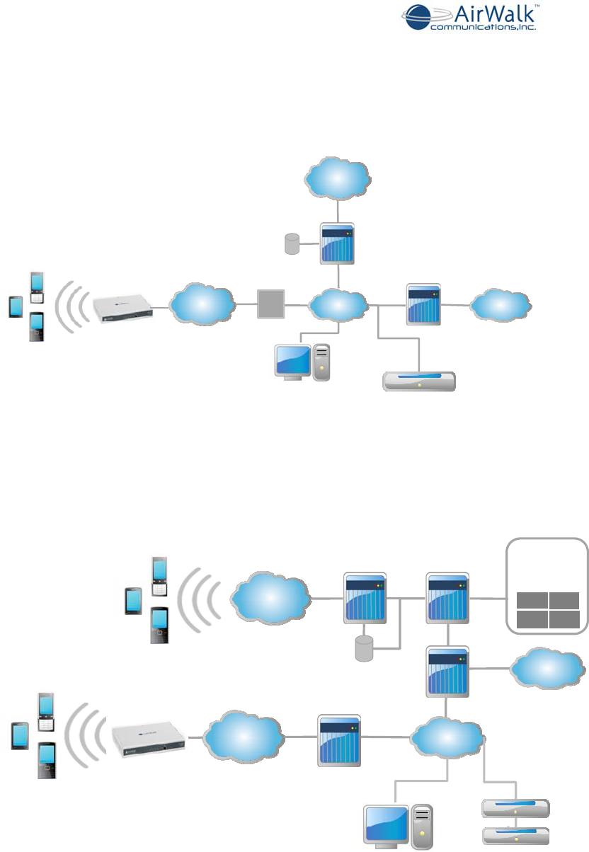
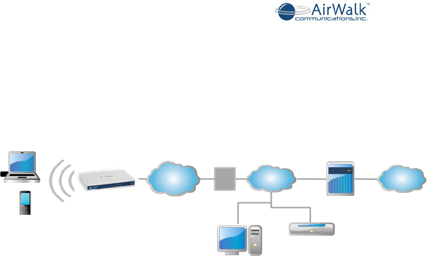
3.2 AW100 Network Diagram
The following diagram is typical network architecture for AW100-1X using IOS5.x
standard interfacing to a CDMA softswitch network.
IPIntranet
HA/AAA
IPBackhaul
PSTN
AirWalkIntegrated
BaseStation
Manager(iBSM)
Internet
MediaGateway/
CDMASoftswitch
PDSN
HLR
ISP
AirWalk
AW100‐1X
The following diagram is typical network architecture for AW100-1X using IOS to SIP
adapter protocol interfacing to an IMS network.
Security
Gateway
(optional)
HA/AAA
IPIntranet
Broadband
IPSec
PDSN
AirWalkIntegrated
BaseStation
Manager(iBSM)
IMS
Core
Convergence
Server
VM MMS
MPC SMSC
CDMA
ServiceLayer
(Subset)
GMSC
Macro
1xRTTRAN
HLR
PSTN
AirWalk
AW100‐1X
AW100 Series System Installation Manual
____________________________________________________________________________
_____________________________________________________________________________
AirWalk Proprietary and Confidential Page 14 of 54
The following diagram is typical network architecture for AW100-DO with connectivity to
data core networks.
IPIntranet
HA/AAA
IPBackhaul
AirWalk
IntegratedBase
StationManager
(iBSM)
Internet
PDSN
ISP
AirWalk
AW100‐DO

AW100 Series System Installation Manual
____________________________________________________________________________
_____________________________________________________________________________
AirWalk Proprietary and Confidential Page 15 of 54
3.3 Hardware Configuration
The AW00 Series IP-RAN is a unique combination radio and controller in one physical
platform that is differentiated from other systems. Other systems have separate radio
and controller platforms which add to cost and complexity in order to support CDMA2000
networks.
The main components are (depending on specific model):
• AW100 (Main Unit)
o CCPB - Call & Channel Processing Board
In case of AW100-1X is referred to as CCPB-1X
• Provides BTS and BSC function
In case of AW100-DO is referred to as CCPB-DO
• Provides RN and RNC function
o FTRB - Femto Transceiver Board
Provides frequency up down function
Offered in 1900 MHz, 800 MHz, 450 MHz frequency bands
o GTIB - GPS & Timing Interface Board
Provides highly accurate position information
o PSU – Power Supply Unit
• Sector RU - Remote RF Unit (Slim Series, for use with MacroCell applications)
o HPAU - High Power Amplifier Unit
• DC RPSU (DC powered configurations)
o DC power distribution unit
o Provided for optional DC powered RU system configurations only
3.3.1 Physical Description
• Main Unit
o Dimension (H x W x D): 1.75 x 12.25 x 9 (Inc), 4.45 x 31.12 x 22.86 (CM)
o 19” EIA Rack x 1 Rack Unit
o Weight: 4 Kg, [2 lbs]
• Remote RF Unit [Slim RU Series]
o Dimension (H x W x D): 3.5 x19 x 18 (Inc), 8.8 x 48.2 x 45.7 (CM)
o 19” EIA Rack x 2 Rack Units
o Weight: 13 kg [29 lbs]
• DC RPSU [DC powered configurations]
o Dimension (H x W x D):1.75 x 19 x 18 (Inc), 4.4 x 48.2 x 45.7 (CM)
o 19” EIA Rack x 1 Rack Unit
o Weight: 2 kg [4.4 lbs]
3.3.2 Typical Configurations
The following shows typical component configurations for common applications.
Macrocell Solution - Omni High Power Systems (20W)
- AW100 Main Unit
- 20W Slim Radio Unit (external RF power amplifier)
- Optional DC RPSU for DC powered systems
AW100 Series System Installation Manual
____________________________________________________________________________
_____________________________________________________________________________
AirWalk Proprietary and Confidential Page 16 of 54
Minicell Solution - Omni Medium Power Systems (up to 4W)
- AW-100 Main Unit
- 4W Slim Radio Unit (external RF power amplifier)
- Optional DC RPSU for DC powered systems
Pico / Enterprise Solution - Omni Low Power Systems (up to 200mW)
- AW100 Main Unit
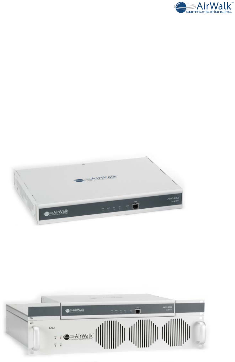
3.3.3 Unit Photographs
The following photographs (front views) show the rack mountable units for AW100
systems:
Pico/ Enterprise Solution - One Carrier / Omni configuration with 200 mW transmit
power
Figure 3-2 AW100-1X Main Unit
Mini / Macro Solution - One Carrier / Omni configuration with 4/20 W External RU
Figure 3-3 AW100-DO with 20W Slim Radio Unit (RU- external RF power amplifier)

AW100 Series System Installation Manual
____________________________________________________________________________
_____________________________________________________________________________
AirWalk Proprietary and Confidential Page 17 of 54
3.4 System Capacities and Specifications
3.4.1 AW-100 Technical Specifications
AW100 Specifications 1xEV-DO Rev A 1xRTT
RADIO
Picocell: 200mW / 23dBm
Transmit Power Microell: 4W / 36dB External RU
Macrocell: 20W / 43dB External RU
Air Interface CDMA2000, 1xEV-DO Rev. A CDMA2000, 1xRTT, IS-95 A/B
Frequency Bands 450 MHz, 800MHz, 1900 MHz 450 MHz, 800MHz, 1900 MHz
Simultaneous Calls Up to 60 Up to 28
Transmit Power
Picocell:200 mW
Macrocell: 0.1 mW with
20W/4W external RU
Picocell: 200 mW
Macrocell: 0.1 mW with
20W/4W external RU
Channel Elements 192 CEs per enclosure 32/64 CE per enclosure
Configuration 1 carrier / 1 sector omni 1 carrier / 1 sector omni
CONTROLLER Handoff Soft/Hard Soft/Hard
Integrated RN, RNC, PCF and O&M BTS, BSC, PCF and O&M
INTERFACES
Core Network
Interface ------------------------- IOS4.2 – 5.0 (CDMA Softswitch)
3GPP2/MMD/SIP ( IMS Network)
PDSN IP-10/100 Base T Ethernet –
(A10, A11) IP-10/100 Base T Ethernet –
(A10, A11)
(AN) AAA+HA IP-10/100 Base T Ethernet –
(A12) IP-10/100 Base T Ethernet –
(A12)
POWER
AC 100 VAC ~240 VAC
DC +12 VDC
Consumption 60W
ENVIRONMENTAL
Temperature Operating 0°C to 50°C (32°F to 122°F)
Humidity 5 to 95% non-condensing
Cooling Forced air
HARDWARE
Dimensions
HxWxD
1.75” x 12.25” x 9”
4.45 cm x 31.12 cm x 22.86 cm
Installation Rack Mount
Weight < 4 lbs; < 2 kg
Cooling Forced air
Type Indoor / outdoor with air conditioned enclosure
Regulatory FCC certified, UL
Mechanical Specification
RF Input and Output Connector SMA Female (Input/Output) From/To RU
GPS Antenna Connector TNC Female Phantom powered
AC Power Connector IEC
RNC/RNC/RN Ethernet
Connectors RJ-45 Ethernet Interface
RU Control and ENV Connectors RJ-45 Serial Interface
Table 3-1 AW100 Mechanical Specifications

AW100 Series System Installation Manual
____________________________________________________________________________
_____________________________________________________________________________
AirWalk Proprietary and Confidential Page 18 of 54
3.4.2 Radio Unit Technical Specification (Slim RU Series)
Tx
Frequency
1930 ~ 1950 MHz N American PCS (A/D)
1945 ~ 1970 MHz N American PCS (B/D/E)
1965 ~ 1990 MHz N American PCS (C/E/F)
869 ~ 894 MHz 800 MHz Cellular Band
A/B/H Sub Bands available 450 MHz Band (incl NMT)
Output Power 43dBm, 20 Watt CDMA
Gain 53 ± 1.0dB
In/Out VSWR 1.5: 1 Output: Isolator Included
Coupling Value 43 ± 1.0dB
Attenuation Rx Freq.
Range 100dBc
Spurious Emission
@43dBm(20W)_1FA
(Band Class 0,2,3,5,7,9)
Fc±750KHz -32dBc Min Max Hold Marker
Fc±1.98MHz -48dBc Min
Fc±2.75MHz -18dBm Min RBW, VBW=30KHZ,
BW=1MHz
Spurious Emission
@43dBm(20W)_1FA
(Band Class 1,4,6,8)
Fc±885KHz -42dBc Min Max Hold Marker
Fc±1.98MHz -52dBc Min
Fc±2.75MHz -18dBm Min RBW, VBW=30KHZ,
BW=1MHz
Over Power 45 + 0.7dBm
Over VSWR
Protection Alarm 3:1 30~43dBm
Over Temp. Protection Alarm @ 90o ± 2 o Base Plate Temperature
Rx
Frequency
1850 ~ 1870 MHz N American PCS (A/D)
1865 ~ 1890 MHz N American PCS (B/D/E)
1885 ~ 1910 MHz N American PCS (C/E/F)
824 ~ 849 MHz 800 MHz Cellular Band
A/B/H available 450 MHz Band (incl NMT)
Gain 24 ± 1.0dB
Gain Flatness 1.0dB max
In/Out VSWR 1.5: 1
Attenuation Tx Freq. Range 100dBc min
Noise Figure 2.2dB max
AW100 Series System Installation Manual
____________________________________________________________________________
_____________________________________________________________________________
AirWalk Proprietary and Confidential Page 19 of 54
Mechanical Specification
RF Input and Output
Connector SMA Female (Input) N Female (Output)
AC Power Connector IEC
RU Control Connector RJ-45 Serial Interface
Weight 13 kg (28.55 lbs.) Per RU
Dimensions ( W x H x D ) 482mm(W) x 457mm(D) x 88mm(H)
19”(H) x 18”(D) x 3.5”(H) 2 Rack Units
Table 3-2 Radio Unit Specifications (Slim RU Series)
3.4.3 Power Supply and Environment Technical Specification
AC Input Power Supply For AC Powered Models
Input Voltage: AC 100Volts ~ 250Volts
Input Frequency: 50Hz ~ 60Hz
AC Power Connector: IEC
Dissipated Power For AC Powered Models
AW100 Main Unit: 60 Watt Max (Efficiency 75%)
Radio Unit (Slim RU) 400 Watt Max (Efficiency 85%)
Maximum AW100 IP-BS 460 Watt Max (Main Unit & 1x Radio Unit)
Table 3-3 AC Power Supply Specifications
DC Input Power Supply For DC Powered Models (DC RPSU)
Input Voltage: DC 12 Volts ~ 30 Volts (float charge compatible)
Fuse Rating: 50A
DC Power Connector (DC
RPSU) Bolted Bus Bar; 2 hole lugs; ¼” holes; ¾” spacing
(Use Blackburn CTL2-2516 or equivalent connector lug)
Dissipated Power For DC Powered Models
AW-100 Main Unit: 60 Watt Max
Radio Unit (Slim RU) 270 Watt Max
Maximum AW-100 IP-BS 330 Watt Max (Main Unit & 1x Radio Unit)
Table 3-4 DC Power Supply Specifications (DC RPSU)
Environment Specification
Operating Temperature -0o ~ +50 o C
Storage Temperature -30 o ~ +60 o
Relative Humidity 5% ~ 95% - Non-condensing
Noise Less than 60dBA, distance 1.5m
Airborne Particle 0 ~ 90 ㎍/㎥
Table 3-5 Environment Specifications
AW100 Series System Installation Manual
____________________________________________________________________________
_____________________________________________________________________________
AirWalk Proprietary and Confidential Page 20 of 54
4 AW-100 Components
4.1 AW-100 Main Unit
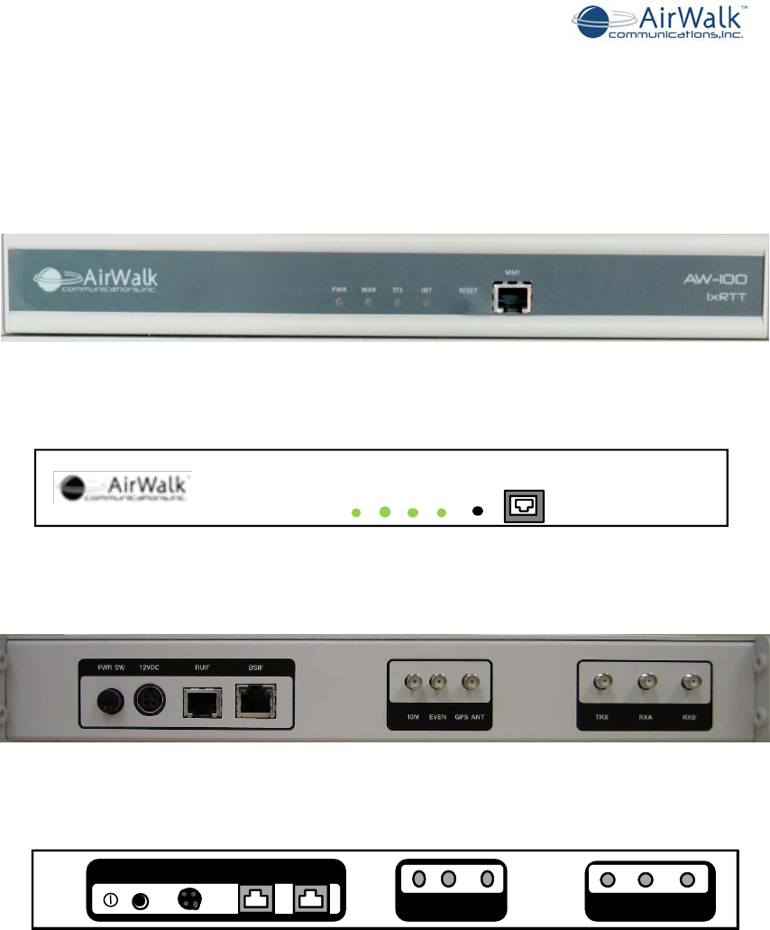
Figure 4-1 AW-100 Main Unit Photo (Front View)
Main +27Vdc IN
AW-IOO
IxRTT
PWRWA NSTS INT RESET
MMI
Figure 4-2 AW-100 – Line Diagram (Front View)
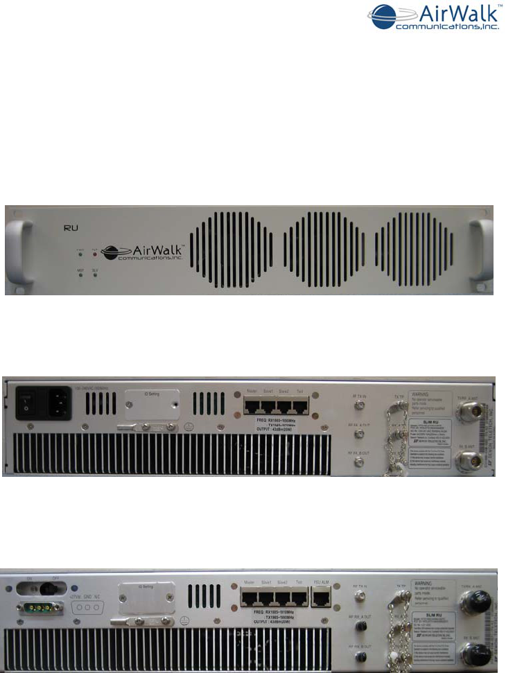
Figure 4-3 AW-100 Main Unit Photo (Back View)
Figure 4-4 AW-100 – Line Diagram (Back View) (AC Version)
PWR12VDCRUIFBSIF
10MEVENGPS
AN
T
TRXRXARXB
AW100 Series System Installation Manual
____________________________________________________________________________
_____________________________________________________________________________
AirWalk Proprietary and Confidential Page 21 of 54
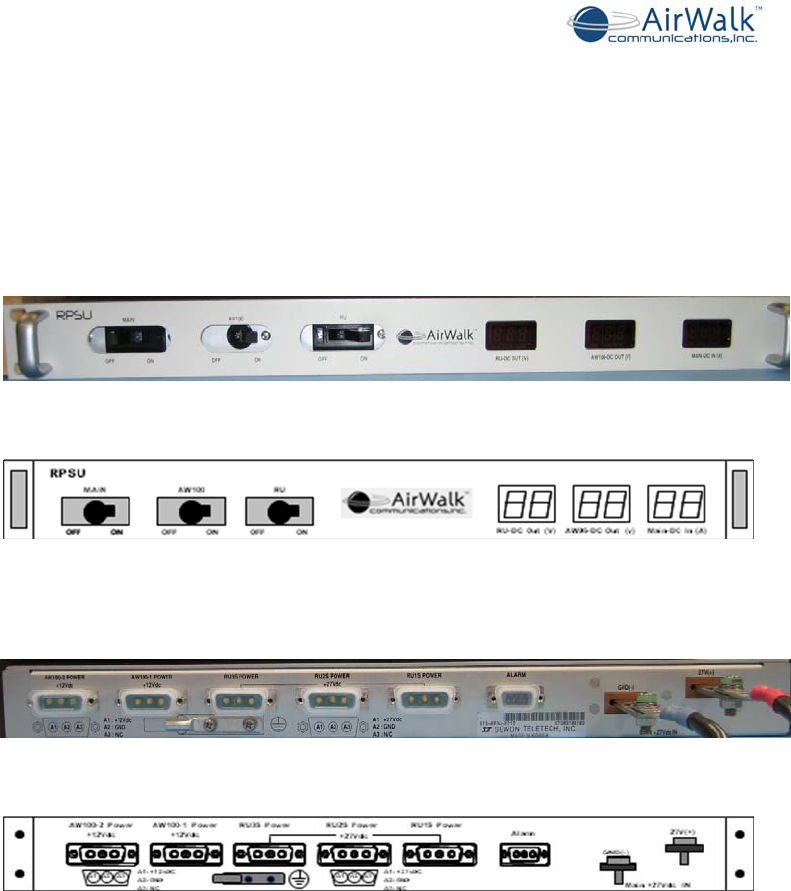
4.2 Radio Unit (RU - Slim RU Series)
The Slim RU series Radio Unit provides high power macrocell capabilities for the omni
site configurations. The Radio Unit functions include a 4W or 20W power amplifier
(measured at the antenna port), RF filtering for Tx and Rx paths, a duplexer function
system, and a power supply. All components are packaged in a compact two rack unit
package.
Figure 4-5 Radio Unit (RU – Slim RU Series) - Photo (Front View)
Figure 4-6 Radio Unit (RU – Slim RU Series) - Photo (Rear View - AC Version)
Figure 4-7 Radio Unit (RU – Slim RU Series) - Photo (Rear View – DC Version)
AW100 Series System Installation Manual
____________________________________________________________________________
_____________________________________________________________________________
AirWalk Proprietary and Confidential Page 22 of 54
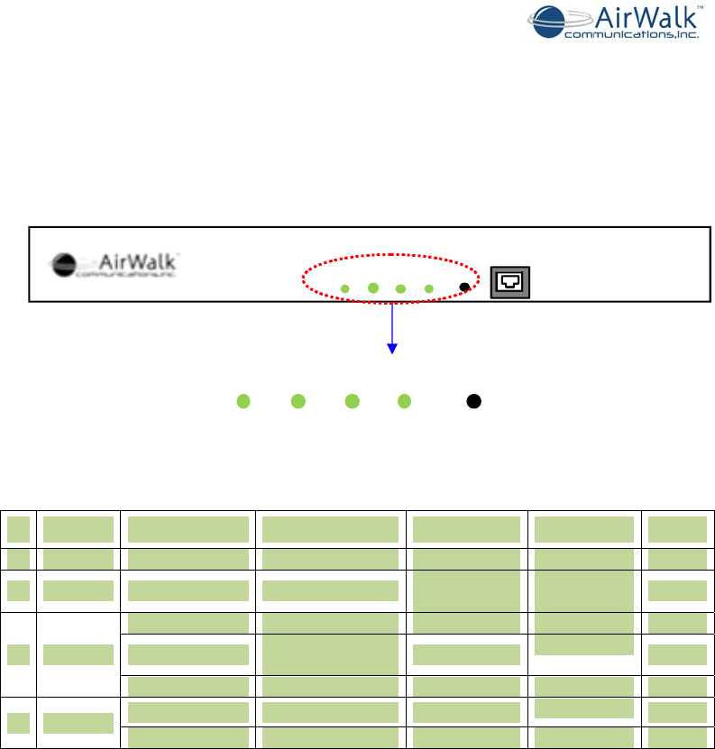
4.3 Optional DC RPSU (DC Power Configurations Only)
DC powered Radio Unit (RU) systems are equipped with a separate DC power
distribution unit which provides a single connection point for DC power source.
Connections are provided for the 12v DC AW100 unit and the 27v DC Radio Unit. Front
panel circuit breakers and voltage/current measurements are provided. The RPSU is also
equipped with an alarm interface to deliver RPSU alarms to the RU system.
Figure 4-8 RPSU DC Distribution Unit - Photo (Front View)
Figure 4-9 RPSU DC Distribution Unit – Line Diagram
Figure 4-10 RPSU DC Distribution Unit – Photo (Rear View)
Figure 4-11 RPSU DC Distribution Unit – Line Diagram (Rear View)
AW100 Series System Installation Manual
____________________________________________________________________________
_____________________________________________________________________________
AirWalk Proprietary and Confidential Page 23 of 54
4.4 Component LED Configuration
4.4.1 CCPB- (Call and Channel Processing Board)
LED status indicators are provided on the AW100 IP-RAN. LED functions are described
in the following pictures and tables.
Main +27Vdc IN
AW-IOO
IxRTT
PWRWAN STS INT RESET
MMI
PWRWANSTSINTRESET
Figure 4-12 LED Highlight
Name Color On Off Brink Note
1 PWR Green Power on Power off
2 WAN Green Disconnect
network Connect
network
3 STS
Green Lock
Orange GPS ANT cable
status is OFF
Green/Orange UNLOCK
4 INT Orange PLL lock
Green Even_sec
Table 4-1 AW100 Indicator Codes
AW100 Series System Installation Manual
____________________________________________________________________________
_____________________________________________________________________________
AirWalk Proprietary and Confidential Page 24 of 54
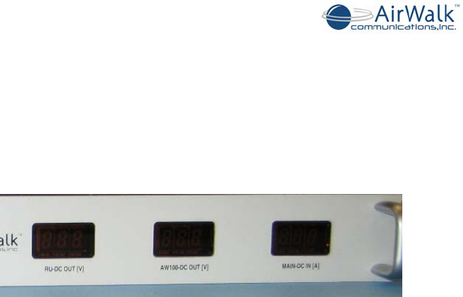
4.4.2 RU DC Power Distribution Unit (RPSU) [DC powered models only]
The RU RPSU (DC Power Distribution Unit) is equipped with a digital voltmeter and
digital ammeter as shown in Figure 4-13.
Figure 4-13 RPSU DC Power Measurement Indicators (Front View)
The following values are displayed on the front panel.
AW100-DC Out (V) : Internal RU control unit voltage (nominally 12-14V)
RUDC Out (V) : Main system DC voltage (nominally 27-28V)
Main DC In (A) : Overall system current consumption (5-50A, load dependent)
Circuit breakers are also provided for system protection. A master circuit breaker controls
power to the complete IP-RAN unit. Individual circuit breakers are provided for protection
of the main unit and RU amplifier system.
Only DC powered models are equipped with the RPSU DC power distribution module.
AW100 Series System Installation Manual
____________________________________________________________________________
_____________________________________________________________________________
AirWalk Proprietary and Confidential Page 25 of 54
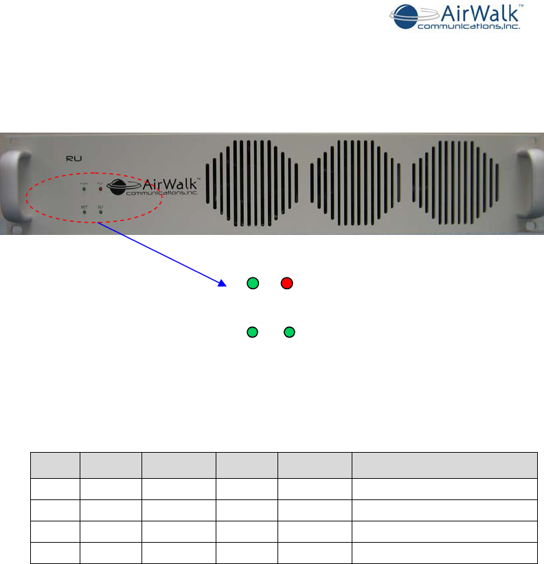
4.4.3 Radio Units Front Panel Indicators (Slim RU Series)
The Radio Unit is equipped with indicators for power, communication activities and
alarms. The location of the RU front panel indicators is shown in Figure 4-14 (each RU).
PWRFLT
MSTSLV
Figure 4-14 Radio Unit Front Panel Diagram
A description of Radio Unit Front Panel indicator functions is shown in Table 4-2.
LED Color On Flash Off Note
PWR Green Normal N/A No Power AFEU power on indicator
FLT Orange Fault N/A Normal RU Alarm(s) detected
MST Green N/A Comm No Comm Communications with AW100
SLV Green N/A Comm No Comm Communications with other RU
Table 4-2 Radio Unit Front Panel Indicator Codes
AW100 Series System Installation Manual
____________________________________________________________________________
_____________________________________________________________________________
AirWalk Proprietary and Confidential Page 26 of 54
5 AW-100 Cabling
5.1 Power Supply Wiring (AC / DC Powered Versions)
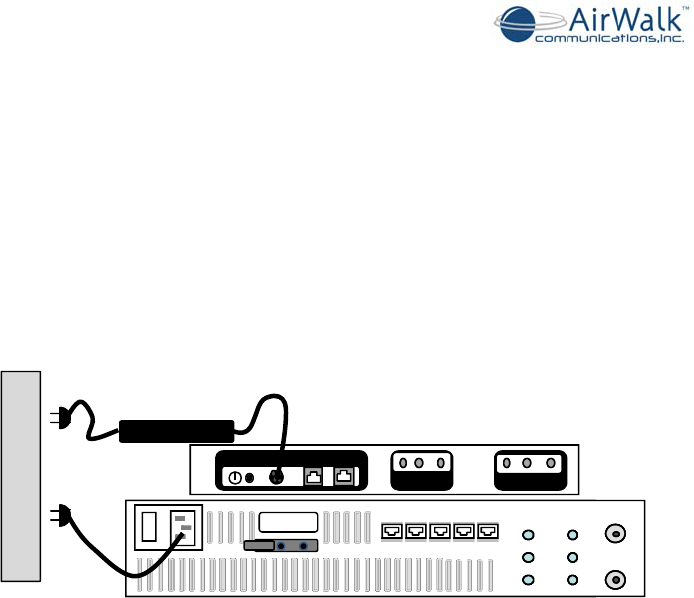
The majority of the AW-100 systems will be powered via the AC/DC power supply.
Connect the AW-100 main unit and if applicable the optional Radio Unit system to
suitable AC power sources as shown in Figure 5-1. Use only the AC / DC power supply
and AC cables provided by AirWalk to ensure continued safe operation.
10MEVENGPS
AN T TRX RXA RXB
PWR 12 VDCRUIF BSIF
ID Setting
MasterSlave1 Slave2
TX TP
RX_A TP
RX_B TP
RF TX I N
RF RX_A OUT
RF RX_B OUT
TX/RX_A ANT
RX_B ANT
TX TP
RX_A TP
RX_B TP
TX TP
RX_A TP
RX_B TP
RF TX IN
RF RX_A OUT
RF RX_B OUT
RF TX IN
RF RX_A OUT
RF RX_B OUT
TX/RX_A ANT
RX_B ANT
TX/RX_A ANT
RX_B ANT
MasterSlave1 Slave2MasterSlave1 Slave2 Test PSU ALM
ID Setting
I
O
AC Power Supply
AC/DC
Figure 5-1 Power Supply Wiring (shown with optional RU)
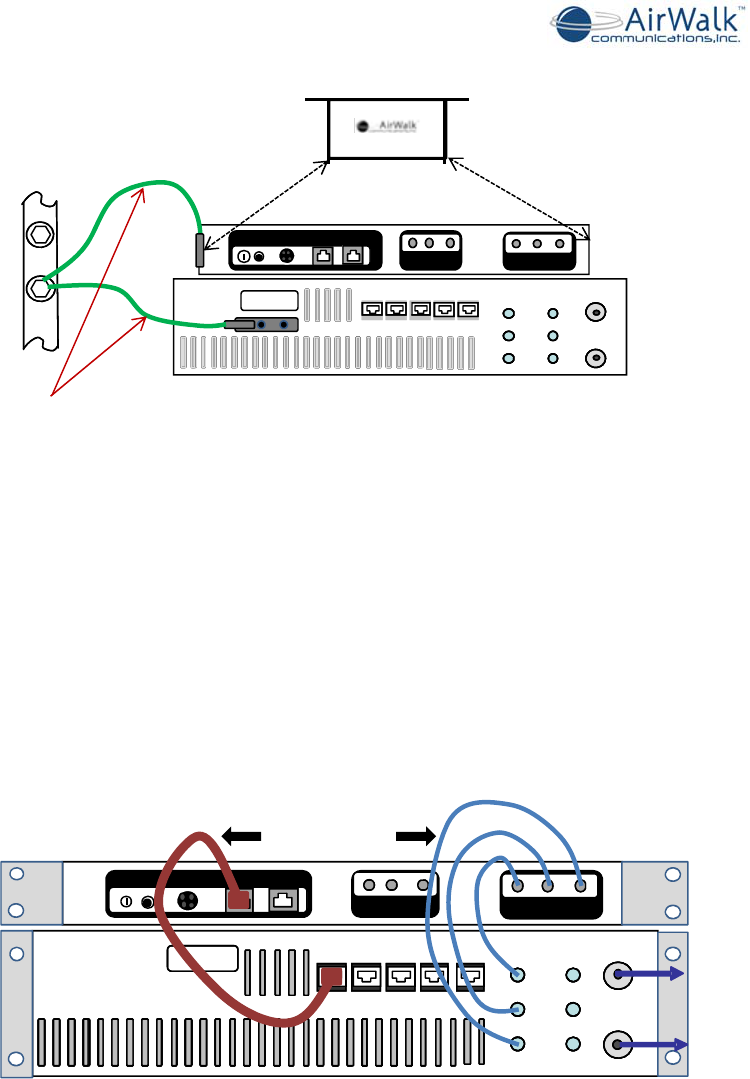
5.2 Grounding
Grounding of the AW-100 system to the local site grounding system is essential for both
safety and proper RF performance. The grounding of the IP-RAN system should be
integrated with the overall site grounding plan as designed by the site planning engineer.
A “halo” perimeter grounding system is recommended for sites equipped with external
antennas that are subject to possible lightning strikes.
A ground strap is provided with each AW-100 system and each RU system to allow
bonding to a ground bus bar or to a common rack grounding point. Each ground wire is
installed on the AW-100 main unit and on the RU amplifier system as shown in Figure 5-
2.
Customer to provide and install (crimp to existing lug) ground cable (AWG 10-12)
between system and the common ground.
Other ground cabling or bus bars used in site installation must be suited to the purpose
and meet any applicable local electrical codes.
Ground connections should be tested for continuity after installation.
AW100 Series System Installation Manual
____________________________________________________________________________
_____________________________________________________________________________
AirWalk Proprietary and Confidential Page 27 of 54
Common Rack Ground
Customer provided and installed ground cables
TX TP
RX_A TP
RX_B TP
TX TP
RX_A TP
RX_B TP
RF TX I N
RF RX_A OUT
RF RX_B OUT
RF TX I N
RF RX_A OUT
RF RX_B OUT
TX/RX_A ANT
RX_B ANT
TX/RX_A ANT
RX_B ANT
MasterSlave1 Slave2MasterSlave1 Slave2 Test PSU ALM
ID Setting
POWER
INPUT
AREA
PWR12VDCRUIFBSIF
RUIFBSIF
10MEVENGPS
AN T TRX RXA RXB
TOP VIEW
Ground Points
Figure 5-2 Ground Wiring (shown with optional RU)
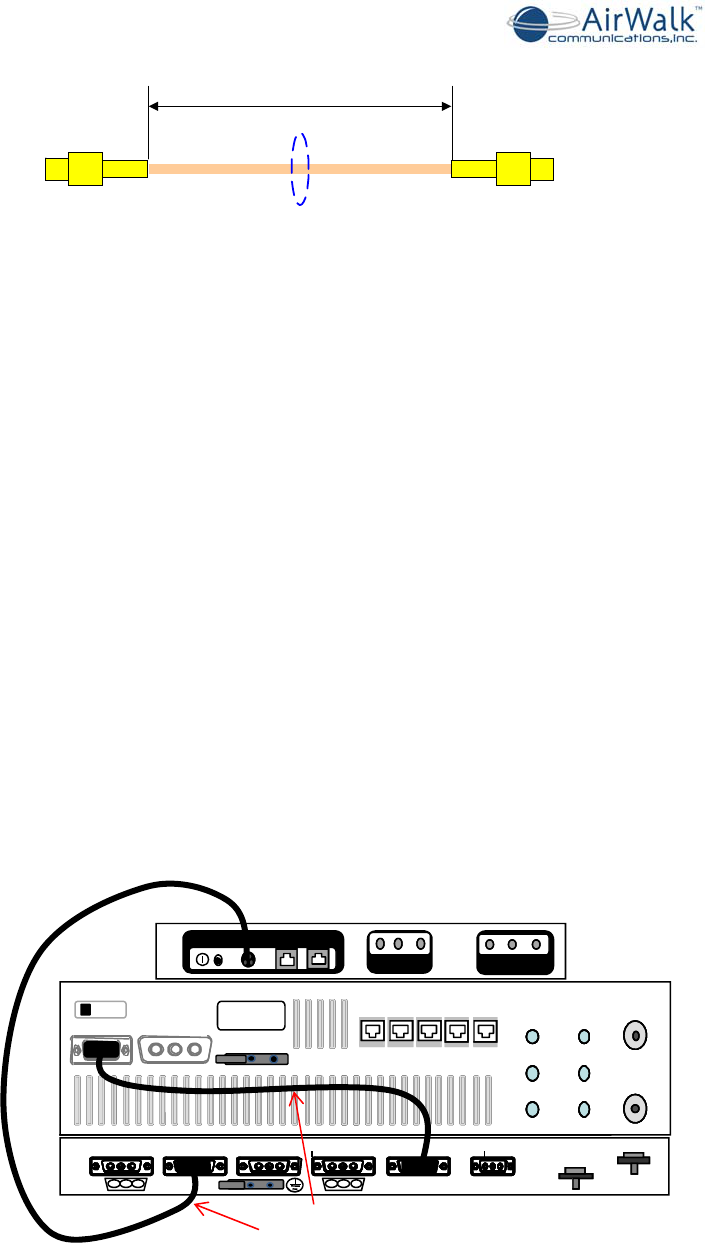
5.3 RF Cabling with RU
The AW-100 transmitter output and diversity receiver inputs are connected to the Radio
Units, which contain the duplexer, LNA (Low Noise pre-Amplifier) and HPA (High Power
Amplifier) functions. Connect using RF jumper cables as shown in Figure 5-3.
Communication between the AW100 and the RU is accomplished with the Master / Slave
LAN cable (KDR45AE). This cable is connected from the AW100 RUIF port to the
Master port on the RU as shown in Figure 5.3.
Use only the cables supplied with the RU system for interconnection to the AW-100.
Cables are labeled for ease of installation. See Figure 5-4 for RF cable specification.
To
Antenna
ID Setting
TX TP
RX_A TP
RX_B TP
TX TP
RX_A TP
RX_B TP
RF TX IN
RF RX_A OUT
RF RX_B OUT
RF TX IN
RF RX_A OUT
RF RX_B OUT
TX/RX_A ANT
RX_B ANT
TX/RX_A ANT
RX_B ANT
Test PSU ALMMaster Slave1 S lave2
POWER
INPUT
AREA
AirWalk
provided cables
PWR12VDC RUIFBSIF
10MEV EN GP S
ANT TR XRX A RXB
Figure 5-3 Radio Unit RF Cabling Diagram
It is important to ensure transmit and receive connections are made correctly to prevent
damage or field operational problems such as:
- Damage due to transmitting into a receiver port
- Crossed over diversity receive ports
AW100 Series System Installation Manual
____________________________________________________________________________
_____________________________________________________________________________
AirWalk Proprietary and Confidential Page 28 of 54
Figure 5-4 AW-100 to RU RF Cable Specification
Connect the external transmission lines from the diversity antenna systems to the RU
Antenna connections as shown in Figure 5-3. External connectors are “N-Type”.
Transmission line (or jumpers to transmission line) type and length will impact the overall link
budget calculations for the cell site. Be sure to include these losses in the RF system design
calculations for coverage.
5.4 Power Supply Wiring (DC Powered Models)
Applications that dictate only DC systems are to be used will require a separate DC
Distribution Unit (RPSU) which provides DC power distribution and over current
protection for connected equipment. The RPSU also provides voltage and current
measurement meters on the front panel. The RPSU will support the AW-100 and the
optional RU.
The RPSU must also be grounded in a similar manner as the other system components.
Connect the AW-100 main unit power interconnect cable between the main unit and the
RPSU Power Supply as shown in Figure 5-5. Use only the cable supplied with the RU
system for this purpose. Tighten connector captivating screws to prevent accidental
disconnection.
DC Cables
(AirWalk provided )
ID Setting
Master Slave1 Slave2
TX TP
RX_A TP
RX_B TP
RF TX IN
RF RX_A OUT
RF RX_B OUT
TX/RX_A ANT
RX_B ANT
ID Setting
TX TP
RX_A TP
RX_B TP
TX TP
RX_A TP
RX_B TP
RF TX I N
RF RX_A OUT
RF RX_B OUT
RF TX I N
RF RX_A OUT
RF RX_B OUT
TX/RX_A ANT
RX_B ANT
TX/RX_A ANT
RX_B ANT
Master Slave1 Slave2Master Slave1 Slave2 Test PSU ALM
ON OFF
+27VDC GND N/C
10MEVENGPS
AN T TRX RXA RXB
PWR 12VDC RUIF BSIF
Main +27Vdc IN
RU3S Power RU2S Power RU1S Power
GND( -)
Alar m
A1: + 1 2 v DC
A2: G N D
A3: N / C
AW100-2 Power
+12Vdc 27V(+)
AW100-1 Power
+12Vdc
+27Vd
c
A1 A2 A3
A1: +27v DC
A2: G N D
A3: N / C
A1 A2 A3
Figure 5-5 AW-100 and RU to RPSU Power Connections [DC models]
SS405
Coaxial Cable
L
AW100 Series System Installation Manual
____________________________________________________________________________
_____________________________________________________________________________
AirWalk Proprietary and Confidential Page 29 of 54
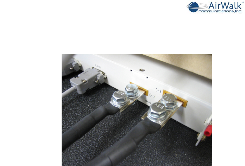
Connect the RPSU main power bus to the external DC power supply system using the
two-hole bolted connections as shown in Figure 5-6.
Power lugs and connection bolts are NOT supplied with the AirWalk system
Figure 5-6 External DC Bus Power Connections [DC models]
The following practices are recommended for DC bus connections:
- Use suitable lugs (Blackburn CTL2-2516 or equivalent lug recommended)
- Use suitable gauge cables (#2/#4 gauge flexible stranded recommended)
- Tighten bolts firmly to prevent movement or arcing
- Use heat shrink tubing, or equivalent, to cover and protect connections
- Power source should be independently fused at the origin point
IMPORTANT – Do not turn on power source until installation is fully completed.
IMPORTANT – Extra care is required when working with high current DC power systems
to avoid personal injury. Protect all DC connections to avoid accidental short circuits.
AW100 Series System Installation Manual
____________________________________________________________________________
_____________________________________________________________________________
AirWalk Proprietary and Confidential Page 30 of 54
5.5 GPS Antenna Cable Wiring
The AW-100 utilizes a 5.0V GPS system. GPS antennas can be ordered as optional
equipment or supplied by customer. Connect the external GPS antenna RF cable to the
“SMA” GPS antenna port on the AW-100 unit as shown in Figure 5-7.
The GPS antenna must be located outdoors in a position to see the general sky. The
GPS antenna must see at least four GPS satellites in the sky to receive enough time
information for proper system operation.
PWR12VDCRUIF BSIF
10MEV EN GP S
ANT TR X RX A RXB
Figure 5-7 GPS Antenna Connection
AW100 Series System Installation Manual
____________________________________________________________________________
_____________________________________________________________________________
AirWalk Proprietary and Confidential Page 31 of 54
6 Frequency Setting Procedures
This section provided to meet regulatory requirements in certain jurisdictions which require local
frequency setting procedures. Normally frequency settings should be made only in the iBSM
system which will subsequently download them to the base station. Refer to the iBSM manuals
for configuration and operating instructions.
6.1 iBSM Management
The AW-100 series base stations are normally managed by the centrally located iBSM
(Integrated Base Station Manager) system which communicates with the AW-100 over an
IP connection.
The iBSM downloads system software and configuration information which includes the
physical FA (Frequency Assignment) for each base station. The base station tunes to the
correct frequency as defined by the BSM configuration files.
Refer to the iBSM operations manual for instructions on base station remote
configuration.
6.2 Local FA Setting
It may be required to set the AW-100 series base station physical FA locally for
specialized test purposes or when the iBSM connection is unavailable (for example
during early RN installations). This can be done using the local MMI (Man Machine
Interface) port and a local PC.
The configuration data downloaded from the iBSM will override local settings when iBSM
connections are established.
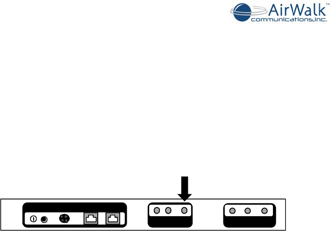
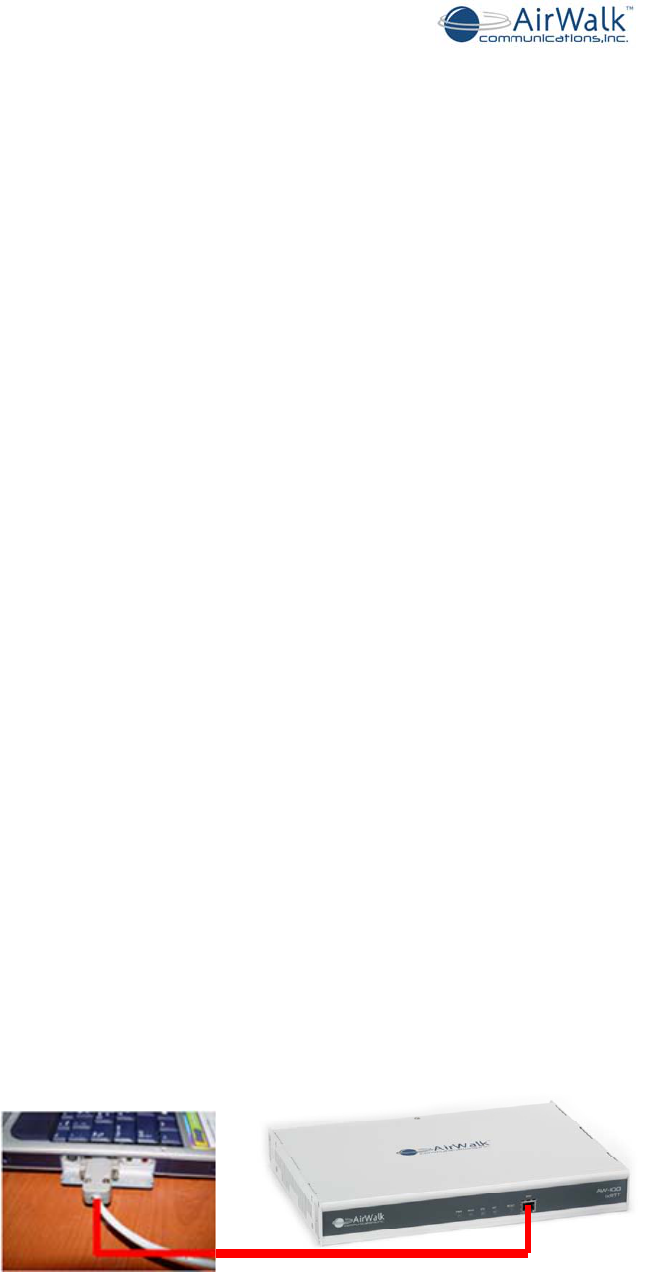
6.2.1 MMI Connection
Connect the serial port of the PC to the “RN MMI” port on the AW-100 front panel. Use
only the Serial MMI cable provided by AirWalk and the following port settings:
• 115200 baud
• 8 bit
• No Parity
• 1 stop bit
• No flow control
Figure 6-1 Serial MMI Cable Connection

AW100 Series System Installation Manual
____________________________________________________________________________
_____________________________________________________________________________
AirWalk Proprietary and Confidential Page 32 of 54
6.2.2 FA Change Procedure
The AW-100 is consists of two different family of IP-RAN.
AW100- 1xRTT
The following menu driven commands permit local changes of the FA.
Step 1
At the prompt enter the following:
> pn3383
// this will take you to the menu screen similar to below:
================= PN 3383 ====================
1. Tx Test
2. Rx Test
3. ParameterSetup
4. Rf Gain Display
5. xcvrSetup
6. ampSetup
7. Normal Gain Display
8. MakeTestCall
9. callClear
10. Overhead Calibration Control
11. Test Phone Setup (678 4711709)
12. Handoff Test
13. Set RF Test
14. System Calibration
15. Display BTS Status
0. Exit
--------------------------------------------------
Select Number ===>
Step 2
Enter the following:
Select number => 5

AW100 Series System Installation Manual
____________________________________________________________________________
_____________________________________________________________________________
AirWalk Proprietary and Confidential Page 33 of 54
// this will take you to the below menu screen.
================= XCVR SETUP ====================
1. SET CHAN
2. SET TX ON
3. SET TX OFF
--------------------------------------------------
4. Show Channel
5. SHOW XCVR MODEL ID
6. SHOW XCVR STATUS
7. SHOW XCVR LEVEL
8. Show RSSI1
9. Show RSSI2
10. Show TSSI
11. Show RSSI1PWR
12. Show RSSI2PWR
13. Show TSSIPWR
14. Show XCVR Temperature
15. Show XCVR Version
16. Show XCVR Reset Reason
17. Show XCVR Cable Status
18. Show XCVR PLL LOCK
19. Show XCVR Power Status
0. Exit
--------------------------------------------------
Select Input Number =====>
Step 3
Enter the following:
Select Input Number => 1
// choosing 1 will take you to the below menu.
AW100 Series System Installation Manual
____________________________________________________________________________
_____________________________________________________________________________
AirWalk Proprietary and Confidential Page 34 of 54
ALPHA : xcvrChangeCh Num [001 ~ 1500] [1175] [/0:Exit]==>
Step 4
From the above menu, type the new channel desired (CDMA channels from 1 to 1500)
and 0 to exit.
Only standard CDMA channel numbers within the designated band capability of the radio
is accepted by the base station.
PS)
Step 5
CDMA Channel to CDMA Frequency Assignment Correspondence
Band CDMA Channel Number
Transmit Frequency Band (MHz)
(Base Station)
0
(800MHz)
1 ≤ N ≤ 799 880.02 ~ 893.37
991 ≤ N ≤ 1023 869.04 ~ 870.00
1
(1900MHz) 0 ≤ N ≤ 1199 1930.00 ~ 1989.95

AW100 Series System Installation Manual
____________________________________________________________________________
_____________________________________________________________________________
AirWalk Proprietary and Confidential Page 35 of 54
AW100- 1xEV-DO
The following menu driven commands permit local changes of the FA.
Step 1
At the prompt enter the following:
> mpt32a
// this will take you to the menu screen similar to below:
================================================
1. Transmitter Test
2. Receiver Test
3. Parameter Setup
4. RF Gain Display
5. XCVR Setup
6. Turn Debug Messages On
7. Turn Debug Messages Off
0. Exit
================================================
Select Number ===>
Step 2
Enter the following
Select Number ==> 5
// this will take you to the below menu screen.
===================== XCVR SETUP ====================
1. Set Channel
2. Set TX On
3. Set TX Off
4. Set Att. Gain
5. Set Reset Reason
-----------------------------------------------------
6. Show Channel
7. Show XCVR Model ID
8. Show Att. Gain
9. Show RSSI1

AW100 Series System Installation Manual
____________________________________________________________________________
_____________________________________________________________________________
AirWalk Proprietary and Confidential Page 36 of 54
10. Show RSSI2
11. Show TSSI
12. Show RSSI1PWR
13. Show RSSI2PWR
14. Show TSSIPWR
15. Show XCVR Temperature
16. Show XCVR Reset Reason
17. Show XCVR Cable Status
18. Show XCVR PLL LOCK
19. Show XCVR Power Status
20. Show TX Status
0. Exit
=====================================================
Step 3
Enter the following:
Select Input Number => 1
// choosing 1 will take you to the below menu.
ALPHA : xcvrChangeCh Num [001 ~ 1500] [1175] [/0:Exit]==>
Step 4
From the above menu, type the new channel desired (CDMA channels from 1 to 1500)
and 0 to exit.
Only standard CDMA channel numbers within the designated band capability of the radio
is accepted by the base station.
PS)
Step 5
CDMA Channel to CDMA Frequency Assignment Correspondence
Band CDMA Channel Number
Transmit Frequency Band (MHz)
(Base Station)
0
(800MHz)
1 ≤ N ≤ 799 880.02 ~ 893.37
991 ≤ N ≤ 1023 869.04 ~ 870.00
1
(1900MHz) 0 ≤ N ≤ 1199 1930.00 ~ 1989.95

AW100 Series System Installation Manual
____________________________________________________________________________
_____________________________________________________________________________
AirWalk Proprietary and Confidential Page 37 of 54
7 Installation Procedures
This Section gives instructions for installing the AW100 Series IP-RAN and for connecting
it to the wireless infrastructure.
Always refer to the Cell Site Installation documents provided by the Project Engineer for
the specific project. These instructions will include site specific installation requirements
in addition to generic installation practices. Site specific installation instructions could also
include special arrangements for power supplies, cabling, backhaul equipment
connections and other specific requirements.
Prior to installation, it is necessary to assign IP addresses and a permanent base station
ID for each IP-RAN system installed. The IP address of the managing iBSM system is
also required. This essential information is needed for site configuration prior to leaving
the site. Once the IP-RAN ID, IP addresses and managing iBSM IP address are installed
in the AW-100 Series IP-RAN base station, the base station can then establish a link to
the iBSM and download the site specific configuration information in addition to any
updated software loads.
It is recommended that the central managing iBSM system be installed and each base
station configuration exists in the iBSM prior to installation of the site. If this preparation
is performed, then each installed base station will obtain a correct configuration
immediately after installation and proper operation can be verified by the installer before
leaving the site.
If the managing iBSM is not present prior to installation, then the IP-RAN can be installed
and will continuously attempt communication with the iBSM until found, and a
configuration downloaded. This allows base stations to be installed prior to the installation
of a central managing iBSM system installation if the project schedule requires early
installation of the base stations.
7.1 Verify Customer Contact and Equipment location
7.1.1 Contact customer1
1) Verify customer and installer contact names for the installation. Contacts names
should be provided for all persons or groups involve in site preparation or planning.
2) Verify a site specific installation plan is available and includes details on:
a) Power connections
b) Backhaul and LAN connections
c) RF antenna system connections
If not verifiable, have main customer contact provided names and method of
contacting.
3) Ensure Installation team (if more than one person on team).
1 NOTE: Make sure all changes are sent to the Installation Coordinator immediately.

AW100 Series System Installation Manual
____________________________________________________________________________
_____________________________________________________________________________
AirWalk Proprietary and Confidential Page 38 of 54
4) Determine when contacts are available for help (e.g.; Time of day, day of week.) for
customer, installation teams and persons involved in the site planning.
5) Obtain any site access or security requirements (e.g.: ID Badges, Card-keys, Keys,
Access codes) required to access installation site.
6) Locate the AirWalk IP-RAN equipment and any required support equipment.
Arrange transportation of equipment to the site, if required.
7) Check for any visible shipment damage to the equipment prior to transportation or
installation. If any damage is observed, then notify the carrier or responsible party
to resolve any insurance inspection issues prior to handling or opening the
packages.
7.1.2 Locate and verify floor space
1) Determine where the IP-RAN equipment is to be installed. Obtain and review site
documentation including diagrams, floor plans and connection requirements before
visiting the site.
2) Visit the site and verify that there is enough space to safely install the AirWalk units
(refer to Site Preparation Checklist in Appendix B).
7.1.3 Uncrate and arrange for packing material disposal2
1) Carefully unpack the AW-100 and related components from packing material.
2) Check for any shipment damage.3
3) Be certain that all components match system order.4
4) Make arrangements for the disposal of all packing material discarded during
installation.
Some crating materials may require return to the manufacturer or warehouse for reuse
and therefore suitable arrangements must be made.
7.1.4 Verify location of power distribution points
1) Locate the customer or site provided power connection points and verify adequacy.
2) AC powered models require a designated 120 VAC minimum 15A or 240 VAC
minimum 7A outlet. No other equipment or receptacles should be connected to this
outlet, other than low power accessories needed to support the IP-RAN operation
such as an Ethernet switch. Use only the 6’ power cord supplied with the IP-RAN
unit.
2 NOTE: If any visible damage, contact the Installation Coordinator immediately.
3 NOTE: Note any damage on the receivables receipt, and Installation Checklist. Contact
the Installation Coordinator immediately.
4 NOTE: If components do not match the system order, contact the Coordinator
immediately.

AW100 Series System Installation Manual
____________________________________________________________________________
_____________________________________________________________________________
AirWalk Proprietary and Confidential Page 39 of 54
3) +12 VDC Models require a rectified and filtered nominal 24V DC power source.
Voltage can range from 22 VDC to 28 VDC to allow use with a float charged battery
system. A designated 50A source with independent over current protection is
required for each IP-RAN unit (fused or circuit breaker). No other equipment should
be connected to the designated circuit breaker.
4) DC powered models require suitable cables with connector lugs to be supplied by the
installer for connection to the DC power source. A #4 or a #2 AWG gauge fine
stranded cable is recommended. Other gauges may be required depending on the
calculated voltage drop. The recommended bolted bus bar connection is a Blackburn
p/n CLT2-2516 or equivalent. Use the bolts supplied with the IP-RAN to connect to
the bus bar.
5) Proper ground connections are essential for both safety and for proper RF
performance. Racks must be equipped with either a grounded bus bar running the
height of the rack, or a common bonding point with a dedicated ground cable
connected to a common cell site ground system. Installation requires that both the IP-
RAN main unit and the RU amplifier system be connected to a common site ground
using ground straps provided with the system. The site ground system must be
independently tested and verified for low resistance to ground.
7.1.5 Verify location of LAN facilities and connection points
1) Locate the customer provided LAN connection points. This could be a dedicated
Ethernet switch, or a set of Ethernet connection points on an IP transport system
terminal.
2) The IP-RAN system requires one IP address for proper operation. RNC(BSC) and
RN(BTS) are working by one.
3) All Ethernet connection should be made using RJ-45 connectors and Category 5 or 6
Ethernet cables capable of supporting 10/100BaseT operation.
4) The static IP Address setting for the IP-RAN will be done after power up using the
web server tool (ref BSM Operations Manual). A site connection and IP addressing
diagram should be prepared for each site and posted at the site after installation.
5) It is strongly recommended that a copy of local site IP routing and addressing
diagrams be sent to AirWalk at the following address to support any remote
diagnostics needed.
Mail to:
AirWalk Customer Service Centre
1830 North Greenville Ave.,
Richardson, Texas 75081
E-mail to:
techsupport@airwalkcom.com
7.1.6 Verify location of RF Antenna Systems, including GPS
1) Locate the site antenna systems, transmission lines and interconnection jumpers.
Follow the site interconnection diagrams provided by the RF Systems Engineer. It is
essential both for proper system operation and for regulatory or licensing
requirements that the antennas are connected to the correct sectors using the correct
jumper cables.

AW100 Series System Installation Manual
____________________________________________________________________________
_____________________________________________________________________________
AirWalk Proprietary and Confidential Page 40 of 54
2) Any discrepancies or problems must be clarified and changes approved by the
designated RF Systems Engineer prior to powering up any base station.
3) Locate the GPS antenna cables and verify the cable is equipped with a TNC
connector for connection to the IP-RAN base station.
Base station operation is still possible without a GPS connection; however, it will not be possible
to implement soft handoff and related features. In cases where GPS is not provided, the base
station will obtain local time from the BSM time server to ensure mobile handset display is
correct.
7.1.7 Verify physical mounting racks are present and suitable
1) Rack mounted IP-RAN systems must be mounted in a suitable 19” EAI standard rack
system that can support the weight of the IP-RAN and also provide adequate rear
support for the power supply. Mounting height requirements are as follows:
a) Main Unit 1 RU (Rack Units) [1 RU = 1.75” (44mm)]
b) RU System 2 RU (Rack Units) [Omni RU System]
c) DC RPSU 1 RU [DC models only]
2) The normal unit stacking lineup is (from bottom to top): RPSU; RU; Main Unit. Do not
change this lineup since all the factory supplied cables are sized for this stack model.
3) It is MANDATORY that suitable rear support be provided at the bottom of the IP-RAN
stack.
a) In the case of 4 post racks, provide rear support using either a rear cross bar
support, a shelf, or mounting brackets for the rear of the chassis.
b) In the case of 2 post racks, provide a suitable heavy duty shelf capable of
holding at least 100 lbs (45 kg). Other options include using a centre
balanced shelf or installing a 4 post conversion kit with a support shelf.
4) Rack mounting screws are to be supplied by the installer as required.

AW100 Series System Installation Manual
____________________________________________________________________________
_____________________________________________________________________________
AirWalk Proprietary and Confidential Page 41 of 54
7.2 IP-RAN Installation Procedures
7.2.1 IP-RAN System physical installation
1) First, install any support shelves or brackets required to provide rear support.
2) Locate the correct holes and install the heaviest rack unit first, which will normally be
the RU system. Installation normally requires at least two people to lift and locate the
unit due to the heavy weight. Secure the RU system to the rack using appropriate
rack mounting screws. Install a screw for each RU rack mounting hole to ensure
enough physical support is provided.
The RU is heavy; At least two people are required to lift and position the RU.
3) Install the RPSU (DC models only) below the RU system. Ensure the RPSU engages
with the rear weight support mechanism (shelf or brackets). Secure the RPSU using
suitable rack mounting screws.
4) Install the IP-RAN main unit above the RU system. Secure the IP-RAN main unit
using suitable rack mounting screws.
7.2.2 Internal system cable connections
1) Install the RU control interface cable between the IP-RAN main unit and RU..
2) Install the optional IPC jumper cable on the IP-RAN front panel.
3) DC Models Only :Install the alarm interface cable between the RPSU and the RU
4) DC Models Only: Install the DC power cable between the RPSU and the RU amplifier
chassis.
5) DC Models Only: Install the DC power cable between the RPSU and the IP-RAN
main unit.
6) Install the RF cables between the IP-RAN main unit and the RU system as illustrated
in this manual. Verify all RF cable connections are correct before proceeding.
Use only cables provided with the IP-RAN system to ensure proper operation.
7.2.3 External system Connections5
1) Establish external grounding points and install ground strap connections from the IP-
RAN main unit and the RU amplifier system to the common site ground points (refer
to Section 5.2 for grounding details). Rack should be equipped with ground bus bars
or bonding points that are cabling to a common cell site ground system.
2) Connect the external Ethernet backhaul connections. Use category 5 or category 6
cable that is certified for use in 10/100 Ethernet systems.
5 WARNING: Make sure all system power supplies are turned off. All breakers /
fuses are pulled on all main and intermediate panels. Then proceed with the
installation.

AW100 Series System Installation Manual
____________________________________________________________________________
_____________________________________________________________________________
AirWalk Proprietary and Confidential Page 42 of 54
3) Connect the external GPS antenna to the IP-RAN GPS antenna input. Use a suitable
RF cable (RG-58 or equivalent) equipped with a TNC connector.
4) Connect the external RF antenna systems. Follow site specific cable installation
drawings prepared by the RF system/planning engineer for cable type and routing.
The IP-RAN unit is equipped with N-type RF connectors. Ensure the individual sector
antenna systems are connected to the correct IP-RAN sector antenna connections.
Incorrect sector connections may cause operational or coverage problems.
5) AC Models Only: Connect the AC line cords for the IP-RAN a dedicated AC power
source.
Only use the cables provided with the system for continued safe operation.
6) DC Models Only: Locate and verify the polarity of the DC power source cables. Slip a
4” length of heat shrink tubing over each DC cable. Connect the cable lugs to the
RPSU DC power bus bars using the supplied connector lug bolts. Tighten the bolts
firmly to ensure a solid electrical connection. The use of electrical contact grease is
acceptable if desired. Slide the heat shrink tubing over the bus bar connection and
use a heat gun to secure the connection.
Short circuits in high current DC power systems can be dangerous. All exposed DC
connections must be protected to prevent accidental short circuits.
7.2.4 Power-up procedure
Verify all connections are correct prior to powering up base station.
1) AC Models Only
a. Switch on the AC power source.
b. Switch on the IP-RAN main unit power switch located on the rear panel power
entry point. The switch is located adjacent to the DC PWR connection.
2) DC Models Only
a. Switch on or engage the circuit breakers at the +12 VDC power source.
b. Switch on the RPSU main circuit breaker located on the RPSU front panel.
c. Use the RPSU voltmeter to verify the presence of +24/27 VDC power.
d. Switch on the RPSU RU circuit breaker located on the RPSU front panel. Note
the increase in current consumption on the RPSU current meter.
e. Switch on the IP-RAN main unit (AW-100) circuit breaker located on the RPSU
front panel. Note the increase in current consumption on the RPSU current
meter.
3) The IP-RAN unit will automatically initiate the startup procedure.
4) Verify communication between the IP-RAN main unit and the RU amplifier system by
observing the communications indicators (led MST) on the RU front panel. The
indicators should on to indicate communication is occurring.

AW100 Series System Installation Manual
____________________________________________________________________________
_____________________________________________________________________________
AirWalk Proprietary and Confidential Page 43 of 54
5) Verify the Ethernet backhaul links are communicating by observing the activity
indicators on the external Ethernet switch. The activity indicators are typically found
on the front panel or adjacent to the connection point on Ethernet switches. The
indicators should be flashing intermittently to indicate the presence of IP packet
activity.
7.2.5 Installation Completion
Completion of the installation requires that all cables be suitably routed and bundled for a
neat appearance. All cables should be tie wrapped as needed to ensure cables will not
move or be stressed in normal system operation. External cables should be labeled in
accordance with the site specific installation drawings prepared by the site planning
engineer.
All garbage and installation materials, including wire clippings and tie wrap ends, must be
removed from the site prior to completing the installation.
7.3 Initial System Configuration
Each IP-RAN system requires configuration of key site specific information prior to
operation to allow the system to communicate and contact the controlling iBSM system.
One this initial information is configured the system will automatically download software
and configuration information from the iBSM. No additional on-site configuration is
required after this initial configuration is completed.
The following items must be configured in the base station after installation using the
Web Server installation support tool:
- IP-RAN IP Address: Locally valid static IP address (allows IP communications)
- IP-RAN Identity: Unique identifier associated with a iBSM site configuration
- Host iBSM IP Address of RNC: IP address of the controlling iBSM (allows initial
contact)
Additional capabilities are provided in the Web Server Installation Tool to identify sub-net
masks and net gateways, and the ability to select optional boot modes.
The required IP addresses and base station identity for a particular site are normally set
up in advance by the network control center engineers prior to site deployment. Ensure
this information has been provided prior to installation configuration.
AW100 Series System Installation Manual
____________________________________________________________________________
_____________________________________________________________________________
AirWalk Proprietary and Confidential Page 44 of 54
7.3.1 Web Server Installation Tool Set-up
The Web Server Installation Tool is built into the IP-RAN base station. Connection to the
tool requires only a PC equipped with an Ethernet capability and a common browser such
as Explorer.
Connection from the PC to the base station is made over the local Ethernet connection at
the cell site, usually via the local on site Ethernet switch (Figure 7-1).
Refer to the Web Server Installation Tool document for complete instructions on
configuring the PC and browser to access the web server tool. Abbreviated instructions
are provided in the remainder of this section for users previously familiar with the Web
Server Tool.
Figure 7-1 Initial Configuration Using Local Web Server
7.3.2 Web Server Connections
There are some rules that should be followed when making the parameter changes.
Some of the parameters have to be used with a valid IP address format such as
“xxx.xxx.xxx.xxx”, where xxx is a digit between 0 to 255.
The parameters that are important for the configuration of the AW100 are Primary IP
Address, Subnet Mask, Host IP Address, and Gateway. In addition BSID, Base Station
ID, should be composed of number between 0 to 4095. The value of 5000 is a special

AW100 Series System Installation Manual
____________________________________________________________________________
_____________________________________________________________________________
AirWalk Proprietary and Confidential Page 45 of 54
BSID number that will be used for the manufacturing default number. This number
should be changed before the operation can begin.
Use these default addresses to access the AW100 functions for the first time using the
PC browser. Enter these IP addresses in the browser address bar to gain access to the
AW100 functions.
Once a base station has been configured, the default addresses are not longer valid.
To gain access locally to a base station that has already been configured (running), use
either the new IP address (the primary address) or a secondary IP address in the AW-
100 IP-RAN system. It depends up the BSID value. This secondary IP address is an
alternate means to access the system from within the unit’s LAN. The secondary IP
Address takes the following format:
172.3X.YYY.ZZZ
X = 0 for 1xEV-DO systems
X= 1 for 1xRTT systems.
Internally, the dotted fields are represented by eight bits per field for a total 32 bits per
address. YYY and ZZZ fields are derived from the BSID by shifting the 12 bit BSID that
range from 0 to 4095 as mentioned above. To calculate the BSID into YYY.ZZZ, shift the
BSID by 4 bits then add the final bits. The final two bits are 01 for RN. For example
BSID = 4095 can be calculated as follow:
Decimal 4095 = hex FFF = bin 1111 1111 1111
Then shift 4 to left then add 01 = 1111 1111 1111 0001
Calculate it back to Hex = FF F1
YYY.ZZZ becomes FF.F1 and this will come up with secondary IP Address.
For the above example of 1xRTT with BSID 4095 will have secondary IP Address as
follow:
172.31.255.241
where X = 1 since it is 1xRTT product with YYY=FF=255 and ZZZ = F1 = 241.
For the factory default setting with BSID=5000, following are secondary IP address:
For 1xRTT system: 172.31.255.251
For EVDO system: 172.30.255.251
You must know either the base station id or the current IP address to access the web
server function when the base station is running.
The Web Server function is also equipped with a security log in to prevent unauthorized
access from the local IP network. The following default log-in parameters are used:
Login ID: air
Password: airairair
AW100 Series System Installation Manual
____________________________________________________________________________
_____________________________________________________________________________
AirWalk Proprietary and Confidential Page 46 of 54
7.3.3 IP-RAN Initial Configuration (default “booting mode”)
Connection the PC to the RN using either the default factory IP address (new systems),
or the primary address or secondary address (systems already configured). The window
shown in Figure 7-2 will appear in the browser:
Figure 7-2 Web Server Login Screen
Enter the default login id and password to gain access to the configuration screen, which looks
similar to Figure 7-3.
Figure 7-3 IP-RAN Configuration Screen (default “booting mode”)
Enter the required information and click on “Submit and Reboot” to set the parameters. The
system will present the screen as shown in Figure 7-4. At this point, the system sets the
configuration parameter and then proceeds to reboot. During reboot, the iBSM contacts and
downloads the full site configuration. The reboot process can be interrupted by clicking on
“RECONNECT”.

AW100 Series System Installation Manual
____________________________________________________________________________
_____________________________________________________________________________
AirWalk Proprietary and Confidential Page 47 of 54
Figure 7-4 IP-RAN Configuration Screen (default “booting mode”)
7.3.4 IP-RAN Re-Configuration (“running mode”)
An IP-RAN equipped with an existing configuration can again be accessed via the Web
Server tool to change parameters. The connection to the IP-RAN must be made using
either the current primary IP address or the secondary address which is based on the
base station id. After connection, the login screen will appear as shown in Figure 7-5,
indicating “running mode”.
Figure 7-5 IP-RAN Re-Configuration Screen (“running mode”)
Enter the default login id and password to access the configuration screen:
AW100 Series System Installation Manual
____________________________________________________________________________
_____________________________________________________________________________
AirWalk Proprietary and Confidential Page 48 of 54
Figure 7-6 IP-RAN Configuration Screen (“running mode”)
Configuration changes are entered using this screen and accepted by the IP-RAN by
clicking on the “Submit” button. However, the new changes will NOT become effective
until the IP-RAN unit is rebooted. This can be done by clicking on the “Reboot” button.
Once the IP-RAN unit reboots, it will use the new configuration information to contact the
controlling iBSM system to download software images and/or configurations, as required
or defined in the “bootoptions” setting.
7.3.5 Additional Operation Tests
Additional operational tests may be required by the RF system/planning engineer, the
network control centre engineers, or others in order to complete the base site installation.
Such tests could include:
- Power output measurement (PPS or PN3383)
- Alarm function testing
- Test calls using mobile handsets or data terminals
- Drive testing and RF coverage/performance measurement
Refer to the individual test checklists for completion and recording of any additional
installation test activities.
7.4 Site Cleanup and Customer Signoff
The following activities must be undertaken prior to completion of the site installation:
- Disposal of all packing and installation materials, including wire clippings
- Replace all equipment, covers, doors and other site equipment

AW100 Series System Installation Manual
____________________________________________________________________________
_____________________________________________________________________________
AirWalk Proprietary and Confidential Page 49 of 54
- Completion of the installation checklist
- Final approval by the relevant customer authority
7.5 Recommended Installation Tools and Supplies
1) Hand Tools:
a) Screwdriver set
b) Pliers set
c) Nut Driver set
d) Cutter set
e) Punch Down tool, or wire-wrap tool (site dependent)
f) RJ-45 crimper tool
2) Test Equipment:
a) Multi-meter and adapter kit
b) PC equipped with Ethernet card and browser
c) RF test set (power measurement, or optionally a CDMA test set)
d) RF adapters
3) Supplies:
a) RJ-45 connectors
b) Cat 5 or 6 Cable
c) Cable tie-wraps
d) Rack mounting screws and related rack hardware
7.6 Troubleshooting Procedures
The AW-100 Series CDMA IP-RAN system is designed to provide reliable and consistent
high performance in all network environments. The installation procedure described in
this manual for the IP-RAN is quite straightforward and simple to implement.
Should problems develop during installation, this section is intended to help locate,
identify, and correct these types of problems. Please follow the suggestions listed in the
following sections prior to contacting the AirWalk Customer Support Center. If you are
unsure of the procedures described in this section, contact the installation coordinator
immediately for clarification.
7.6.1 Before Calling for Assistance
1) If difficulty is encountered with a specific component of the IP-RAN, refer back to the
Installation Section for that component.
2) Check the cables and connectors to ensure that they have been properly connected
and the cables/wires have not been crimped or impaired in some way during
installation.

AW100 Series System Installation Manual
____________________________________________________________________________
_____________________________________________________________________________
AirWalk Proprietary and Confidential Page 50 of 54
As a rule, 90% of component problems can be attributed to wiring and connector
problems).
a) Check cable
b) Check connector
c) Check for solid connection
d) Check with site specific installation documentation
3) Make sure that all power cords are properly attached to each IP-RAN component. Be
certain that all power cords are plugged into a functioning electrical outlet. Use the
PWR LED’s and the voltage meters to verify each unit is receiving power. Check
intermediate breakers or fuses.
4) If the problem is isolated to something other than the IP-RAN, contact the appropriate
parties responsible for that system.
5) Verify whether or not the problem is corrected. If not, go to Step 6 below. If the
problem is corrected, continue with installation.
6) If the problem continues after completing Step 4 above, contact the Installation
Project Manager to determine the next course of action. If the problem persists after
review, then contact the AirWalk Customer Support Center for assistance.
7.6.2 When Calling for Assistance
Please be prepared to provide the following information.
1) A complete description of the problem, including the following points:
a) The nature and duration of the problem
b) Situations when the problem occurs
c) The components involved in the problem
d) Any particular application that, when used, appears to create the problem
2) A record of changes that have been made to the IP-RAN configuration prior to the
occurrence of the problem.
3) Any changes to the system should all be noted.
AirWalk Customer Service Center
1830 North Greenville Ave.,
Richardson, Texas 75081
E-mail to:
techsupport@airwalkcom.com

AW100 Series System Installation Manual
____________________________________________________________________________
_____________________________________________________________________________
AirWalk Proprietary and Confidential Page 51 of 54
8 Appendix A - Acronyms
Acronym Description
2G Second Generation in CDMA wireless network
3G Third Generation in CDMA wireless network
AAA Authentication, Authorizing, and Accounting
BHCA Busy Hour Call Attempts
BSC Base Station Controller
BTS Base station Transceiver Subsystem
CA Call Agent – Softswitch
CALEA Communications Assistance for Law Enforcement Act
CDMA Code Division Multiple Access
CPE Customer Premise Equipment
CPU Central Processing Unit
CSM5000 Cell Site Modulator 5000 (CDMA ASIC chip released by Qualcomm for cdma2000)
DC Direct Current
DHCP Dynamic Host Control Protocol
EVDO Evolution Data Only
EVRC Enhanced Variable Rate CODEC
FA Frequency Assignment
FCC Federal Communications Commission
FM Fault Management
FO Frame Offset
GPS Global Positioning System
HLR Home Location Register
HO Handoff
HSS Home Subscriber Server
iBSM Integrated Base Station Management
IF Intermediate Frequency
IMSI International Mobile Subscriber Identity
I-CSCF Interrogating Call Session Control Function
IOS Interoperability System
IP Internet Protocol
IKE Internet Key Exchange
IMS IP Multimedia Subsystem
IPSec IP Security
LAN Local Area Network
MG Media Gateway
MN Mobile Node
MS Mobile Station
MSC Mobile Switching Center
MTBF Mean Time between Failure
PCF Packet Control Function in BSC
PSTN Public Switched Telephone Network
QCELP Qualcomm Code Excited Linear Prediction
QOF Quasi-Orthogonal Function
QOF Quasi Orthogonal Function
QoS Quality of Service
RAN Radio Access network

AW100 Series System Installation Manual
____________________________________________________________________________
_____________________________________________________________________________
AirWalk Proprietary and Confidential Page 52 of 54
Acronym Description
RC Radio Configuration
RN Radio Node
RF Radio Frequency
RNC Radio Network Controller
RPSU Remote RF Power Supply Unit
RTP Real-Time Transport Protocol
RU Remote RF Unit
SDU Selection and Distribution Unit
SMS Short Message Service
SS Soft Switch
SIP Session Initiation Protocol
S-CSCF Serving Call Session Control Function

AW-100 Series System Installation Manual
__________________________________________________________________________
____________________________________________________________________________
AirWalk Proprietary and Confidential Page 53 of 54 7/28/2010
9 Appendix B - Installation Certification Document
Date: ______________________________________________________
Subject: _________________________________________________
The subject AW-100 Series IP-RAN has been installed and proper system operation has been
verified on this date.
_______________________________________ __________________
Installation Team Representative Date
_______________________________________ __________________
Authorized Carrier Representative Date

AW-100 Series System Installation Manual
__________________________________________________________________________
____________________________________________________________________________
AirWalk Proprietary and Confidential Page 54 of 54 7/28/2010
This Page Marks the End of this Document