Airespace 1200D IEEE 802.11 a/g Wireless LAN Access Point User Manual AP Ext QIG
Airespace IEEE 802.11 a/g Wireless LAN Access Point AP Ext QIG
Contents
- 1. DoC
- 2. Users Manual Ext Version
- 3. Users Manual Int Version
- 4. Users Manual Int Verison
Users Manual Ext Version
11/16/04 © 2004 All Rights Reserved.
90-100906-000 Rev 1
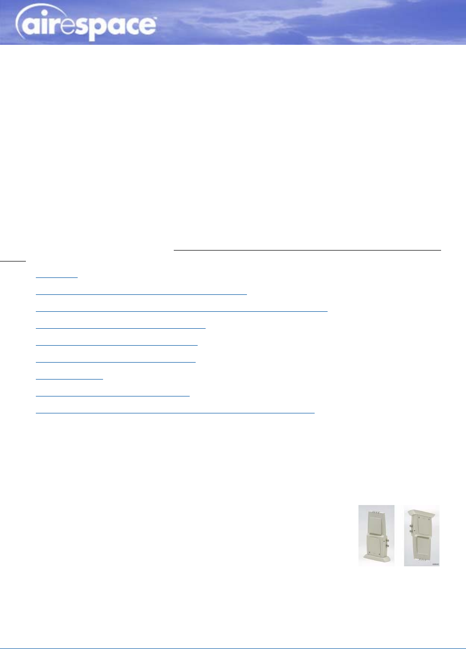
External-Antenna 1200 and 1250 Airespace AP
Quick Installation GuideExternal-Antenna Airespace Access Point Quick Installation Guide
System Release 2.1
This Guide contains several sections allowing you to install an AS-1200-BG-EXT, OAW-1250BGE,
AS-1200-ABG-EXT, OAW-1250ABGE Airespace Access Point or an AS-1200-ABG-EXT-RE or
OAW-1250ABGR Remote Edge Access Point (REAP). These models contain internal 802.11a and
802.11b/g antennas and connectors for optional external 802.11a and 802.11b/g antennas.
When you are installing an AS-1200-BG-INT, OAW-1250BG, AS-1200-ABG-INT, or OAW-1250ABG
Airespace Access Point with internal 802.11a and 802.11b/g antennas and no connectors for optional
external antennas, please refer to the Internal-Antenna Airespace Access Point Quick Installation
Guide.
•Overview
•Step 1: Collecting Required Tools and Supplies
•Step 2: Configuring the Airespace AP or REAP Before Installation
•Step 3: Preparing Mounting Locations
•Step 4: Mounting the Airespace APs
•Step 5: Returning MAC Information
•Planning Notes
•FCC Statements for Airespace APs
•Industry Canada Required User Information for Airespace APs
ATTENTION!Special Considerations
While Airespace Access Points have been engineered for easy installation, there are some guidelines
that are very important to the end users:
•PLACE Airespace APs NO MORE THAN 140 FEET APART FROM EACH OTHER. Placing Airespace
APs further apart almost always results in poor coverage.
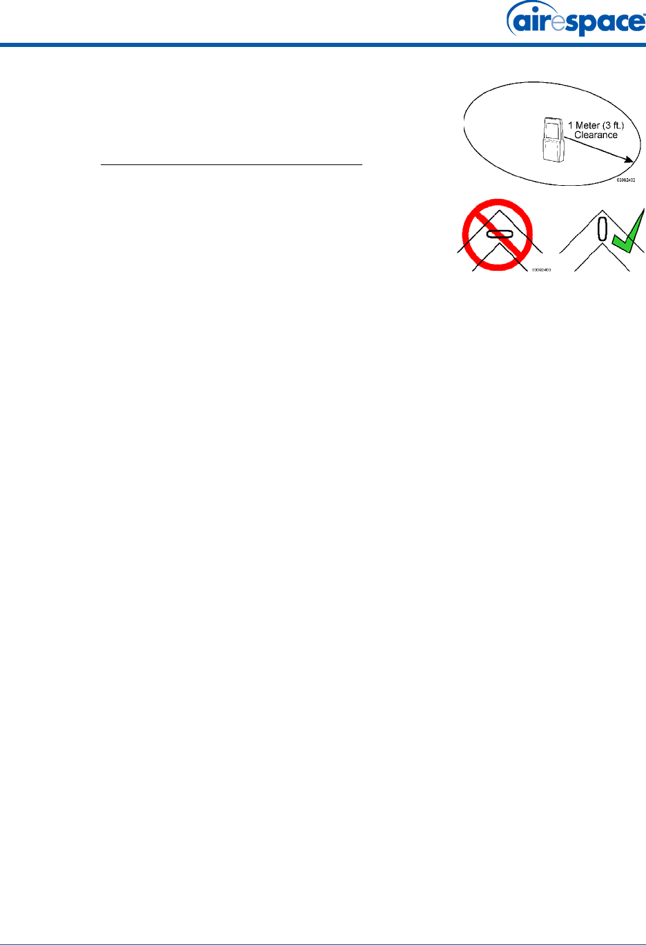
•MAKE SURE THAT Airespace APs ARE INSTALLED VERTICALLY.
When Airespace APs are installed vertically, either standing up
in a plenum or hanging from a ceiling, this creates the largest
coverage area per Airespace AP. Hanging Airespace APs from
the ceiling provides the best RF coverage.
11/16/04 External-Antenna Airespace Access Point Quick Installation Guide
90-100906-000 Rev 1 2
•DO NOT MOUNT Airespace AP ANTENNAS WITHIN ONE METER
(3 FT.) OF ANY METAL OBSTRUCTIONS. THE RF WAVES FROM
Airespace APs ARE BLOCKED AND/OR REFLECTED BY METAL
OBJECTS, such as metal HVAC ducts, conduit, pipes,
bookcases, elevator shafts, stairwells, and metal walls. REFER
TO THE Airespace Access Point Deployment Guide BEFORE
MOUNTING Airespace APs NEAR METAL OBSTRUCTIONS.
•WHEN MOUNTING AN Airespace AP IN THE CORNER OF A
RIGHT-ANGLE HALLWAY INTERSECTION, MOUNT THE
Airespace AP AT A 45-DEGREE ANGLE TO THE TWO HALLWAYS.
The Airespace AP internal antennas are not omnidirectional,
and cover a larger area when mounted this way.
•External antennas are NOT to be used when installing Airespace
APs and REAPs in a plenum.
•MAKE SURE that plenum-mounted Airespace APs and REAPs are powered using Power Over
Ethernet (POE) and use only the metal brackets (not the Ceiling-Mount Base or the
Hanging-Ceiling Clips) to comply with safety regulations.
•DO NOT MOUNT Airespace APs OUTSIDE BUILDINGS.
•DO NOT MOUNT Airespace APs ON BUILDING PERIMETER WALLS UNLESS THE OPERATOR
WANTS TO PROVIDE COVERAGE OUTSIDE THE BUILDING.
11/16/04 Overview
90-100906-000 Rev 1 3
OverviewOverview
This guide is designed to provide you with the information needed to mount AS-1200-BG-EXT
OAW-1250BGE, AS-1200-ABG-EXT, and OAW-1250ABGE Airespace Access Points, and
AS-1200-ABG-EXT-RE and OAW-1250ABGR Remote Edge Access Points (REAPs). Airespace APs and
REAPs are part of the innovative Airespace Wireless Enterprise Platform (Airespace System), and
require no manual configuration after they are mounted.
This document assumes that a site survey has been performed as described in the Airespace Access
Point Deployment Guide document, that Airespace AP and REAP locations and mounting options have
been selected, and that you have one Airespace AP or REAP per indicated location.
After the site survey is done, you should have a map indicating the following:
•Airespace AP and REAP locations.
•Airespace AP and REAP mounting options: hanging from a ceiling, in the ceiling plenum,
projecting away from the wall, flat against the wall, or using the Ceiling-Mount Bezel Kit.
•Airespace AP and REAP power options: power supplied by the AC-to-DC power supply orderable
from the factory, or Power over Ethernet (PoE) from the Airespace WLAN Switch, another
network device, or a PoE injector/hub (usually located in a wiring closet).
If you do not have a map, make one so you can record the MAC addresses from each location and
return them to the to the person who is planning or managing this wireless network.
Refer to the following sections to install the Airespace APs.
For more details about Airespace AP and REAP installations, refer to the Planning Notes section at the
end of this document.
DANGER: Plenum-mounted Airespace APs and REAPs MUST BE powered using
Power Over Ethernet (POE) to comply with safety regulations.
Note: When mounting Airespace APs and REAPs, make sure to maintain a 20 cm
(8 in.) separation between the Airespace APs or REAPs and bystanders to comply
with FCC RF exposure regulations. Refer to the FCC Statements for Airespace APs
section for more information.
11/16/04 Step 1: Collecting Required Tools and Supplies
90-100906-000 Rev 1 4
Step 1: Collecting Required Tools and SuppliesStep 1: Collecting Required Tools and Supplies
•One Airespace AP or REAP per location.
•Airespace AP and REAP Mounting Kits, factory-supplied with each Airespace AP.
•Optional Airespace AP and REAP Mounting Kits, factory-orderable.
•Optional AC-to-DC external power supplies, factory-orderable. Note that this option requires
the power cable to be run through the plenum in a metal conduit to meet safety requirements.
•Optional external 802.11b/g antennas.
•Map showing Airespace AP and REAP locations, and mounting and power options.
•Screwdrivers, drills, and ladder.
•An assortment of sheet metal and drywall screws and toggle bolts.
•CAT-5 (or higher) cables to connect the Airespace AP and REAP locations and the Airespace
WLAN Switch or other network device.
•Optional Kensington MicroSaver Security Cable to secure each Airespace AP and REAP.
Continue with Step 2: Configuring the Airespace AP or REAP Before Installation.
11/16/04 Step 2: Configuring the Airespace AP or REAP Before Installation
90-100906-000 Rev 1 5
Step 2: Configuring the Airespace AP or REAP Before InstallationStep 2: Configuring the
Airespace AP or REAP Before Installation
The following procedures are designed to make sure that your Airespace AP physical installation goes
smoothly and that initial operation is as expected. If you are unable to prepare your Airespace AP for
deployment, this Step also describes RMA (Return Material Authorization) procedures.
•Preparing a Version 1.2 Airespace AP for installation in a Version 2.0 Airespace System
•Preparing a Version 2.0 Airespace AP or REAP or Alternate Preparing a Version 2.0 Airespace AP
or REAP for installation in a Version 2.0 Airespace System
If you are unable to perform either of previous procedures, refer to the RMA Procedures section in the
Airespace Product Guide.
Preparing a Version 1.2 Airespace APPreparing a Version 1.2 Airespace AP
If your Airespace AP has Airespace Operating System 1.2 or an earlier version loaded on it, or if you do
not know what version the Airespace AP has loaded on it, use this procedure. If your Airespace AP is a
REAP or has Airespace Operating System 2.0 or later loaded on it, use the Preparing a Version 2.0
Airespace AP or REAP procedure below.
Configuration SetupConfiguration Setup
Does My Configuration Qualify for this Procedure?Does My Configuration Qualify for this Procedure?
•You must have a version 2.0 Airespace Switch or Appliance on its own subnet that can be
reconfigured back and forth between Layer 2 and Layer 3 LWAPP operation. If you do not have
a spare or depot Airespace Switch or Appliance that can be reconfigured back and forth
between Layer 2 and Layer 3 operation, refer to RMA Procedures later in this document to RMA
your version 1.2 Airespace APs.
•Alternatively, you may have a version 2.0 Airespace Switch or Appliance that is part of a
mobility group that can be reconfigured back and forth between Layer 2 and Layer 3 operation.
If you do not have a mobility group of Airespace Switches and Appliances that can be recon-
Note: Perform either of the following two procedures on each Airespace AP or REAP
BEFORE deploying the Airespace AP or REAP in its final location.
Note: This procedure assumes that you are preparing a version 1.2 Airespace AP to
interoperate with a version 2.0 Airespace Switch or Appliance. When you are
preparing a version 1.2 Airespace AP to interoperate with a version 1.2 Airespace
Switch or Appliance, use the procedure found in the version 1.2 Airespace Access
Point Quick Installation Guide.
11/16/04 Step 2: Configuring the Airespace AP or REAP Before Installation
90-100906-000 Rev 1 6
figured back and forth between Layer 2 and Layer 3 operation, refer to RMA Procedures later in
this document to RMA your version 1.2 Airespace APs.
•If your version 1.2 Airespace AP(s) cannot be configured for any other reason using the
following procedure, refer to RMA Procedures in the Airespace Product Guide.
Configuration Steps for an Airespace APConfiguration Steps for an Airespace AP
1. Configure the Airespace Switch or Appliance in LWAPP Layer 2 Mode (use the CLI command
show switchconfig to determine the mode; if it is set to layer 3, use the CLI command config
switchconfig mode L2 to change it to Layer 2). Make sure the Airespace Switch or Appliance DS
Port is connected to the network. Use CLI, Web Browser and/or ACS procedures as described in
the Airespace Switch or Appliance Quick Install Guide and the Airespace Product Guide.
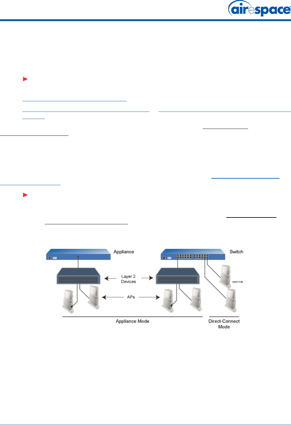
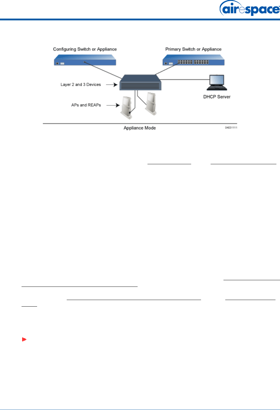
-Make sure Airespace AP ports are available (either Direct-Connect Mode or Appliance
Mode).
-Set the Airespace Switch or Appliance as the Master, so new Airespace APs always
associate with it. Use the CLI command show network config to determine if the
Airespace Switch or Appliance DS Port is the Master. If it is not, make it the Master with
the CLI command properly, make sure to use the CLI command config network
master-base disable.
-Refer to the Airespace Product Guide for other settings.
(Note that Layer 3 and Layer 2 LWAPP operation can be switched back and forth as described in
the Solutions section of the Airespace Product Guide.)
2. Take the Airespace AP out of the box and plug it into a front-panel 10Base-T connector on the
Master Switch (Direct-Connect mode), or through the same subnet that Airespace Switch or
Appliance is on (Appliance Mode).
3. Apply power to the Airespace AP:
-Use 802.3af-compliant Power Over Ethernet (PoE) from the Airespace WLAN Switch or
from an orderable inline power injector. If you do not have PoE available, use an
orderable external AC-to-48 VDC Power Supply plugged into the side of the Airespace
AP.
-After powering up the Airespace AP, the RED Alarm LED comes on for a short period
(about 15-20 seconds) and then all the LEDs blink sequentially back and forth,
indicating that the Airespace AP is trying to find an Airespace Switch or Appliance to
connect to. This can continue for up to five minutes. If the Airespace AP remains in this
mode for more than five minutes, the Airespace AP is unable to find the Master
Airespace Switch or Appliance. Check the connection between the Airespace AP and the
Airespace Switch or Appliance and make sure the Airespace AP and the Airespace
Switch or Appliance are on the same subnet.
-If the power light does not come on, check the power (it can be powered either with
Power over Ethernet or a from an orderable Airespace AP External Power Supply.
-Make sure that a DHCP server is configured in the Airespace Switch or Appliance for the
Management Interface using the CLI, Web Browser, or ACS interface, and that the
DHCP server is operating correctly.
-Once the Airespace AP finds the Airespace Switch or Appliance, it attempts to download
the new Airespace Operating System code if the Airespace AP code version differs from
the Airespace Switch or Appliance code version. While this is happening, the LEDs on
the top of the Airespace AP blink on and off together.
4. Once the Airespace Operating System code download is successful, the Airespace AP reboots.
The GREEN LED turns on and the two YELLOW LEDs indicate the states of the 802.11a and
11/16/04 Preparing a Version 2.0 Airespace AP or REAP
90-100906-000 Rev 1 7
802.11b/g networks. If any part of the network is disabled in the Airespace Switch or Appli-
ance, the corresponding YELLOW LED remains off.
-Note that the Red LED can light for a short period (10-20 seconds) when the Airespace
AP reboots. If the RED LED comes on AND STAYS ON for more than a minute,
disconnect the Airespace AP and call Airespace Global Services & Support.
-Use the CLI command show ap summary. If the new Airespace AP appears on the list, it
has been configured successfully.
-From the CLI, Web Browser or ACS interface, configure the Airespace AP with its
Primary, Secondary and Tertiary Airespace Switch or Appliance names as described in
the Airespace Product Guide.
-If you will be using the Airespace AP in a mobility group, set the mobility group name
using the CLI, Web Browser or ACS interface.
-If required, use the CLI, Web Browser or ACS interface to customize the Airespace
AP-specific 802.11a, 802.11b and 802.11g network settings. Once again, the two
YELLOW LEDs indicate the states of the 802.11a and 802.11b/g networks. If any part of
the network is disabled, the corresponding YELLOW LED remains off.
5. If everything works (the GREEN LED is on and the RED LED is off), disconnect the Airespace AP
and take it to its final destination and install it as described in this document. If your Airespace
AP fails this visual test, refer to RMA Procedures in the Airespace Product Guide to return your
Airespace APs.
6. When you have installed and powered up the Airespace AP in its final destination, verify that
the LEDs are in the same state they were in at the end of Step 4.
-If no LEDs are on, the Airespace AP is most likely not receiving power.
-If the LEDs blink sequentially back and forth for more than five minutes, the Airespace
AP is unable to find its Primary, Secondary or Tertiary Airespace Switch or Appliance.
Check the connection between the Airespace AP and the Airespace Switch or Appliance,
and make sure the Airespace AP and the Airespace Switch or Appliance are either on
the same subnet or that the Airespace AP has a route back to its Primary, Secondary
and Tertiary Airespace Switches and Appliances.
-If the Airespace AP is not on the same subnet as the Airespace Switch or Appliance,
make sure there is a DHCP server on the same subnet as the Airespace AP. Also, make
sure that the route between the Airespace AP and the Airespace Switch or Appliance
can process IP fragmented packets.
After you have prepared all Airespace APs, reconfigure the Airespace Switch or Appliance so it is not the
Master. A Master Airespace Switch or Appliance should only be used for configuring Airespace APs and
not in a working network. Note that the Master Airespace Switch or Appliance is normally not used in a
deployed network, so the Master Airespace Switch or Appliance setting is automatically disabled upon
reboot or AireOS code upgrade.
After completing Step 2: Configuring the Airespace AP or REAP Before Installation for all Airespace APs
and REAPs, continue with Step 3: Preparing Mounting Locations.
Preparing a Version 2.0 Airespace AP or REAPPreparing a Version 2.0 Airespace AP or REAP
If your Airespace AP has Airespace Operating System 2.0 or a later version (which includes all REAPs)
loaded on it, continue with this procedure. If your Airespace AP has Airespace Operating System 1.2 or
earlier loaded on it, or if you do not know what version the Airespace AP has loaded, use the Preparing
a Version 1.2 Airespace AP procedure above.
11/16/04 Preparing a Version 2.0 Airespace AP or REAP
90-100906-000 Rev 1 8
Configuration SetupConfiguration Setup
Does My Airespace AP Qualify for this Procedure?Does My Airespace AP Qualify for this Procedure?
•If your 2.0 or later version later Airespace AP(s) or REAP(s) cannot be configured for any
reason using the following procedure, refer to RMA Procedures in the Airespace Product Guide.
Configuration Steps for an Airespace AP or REAPConfiguration Steps for an Airespace AP or REAP
1. Configure the Airespace Switch or Appliance in LWAPP Layer 3 Mode (use the CLI command
show switchconfig to determine the mode; if it is set to layer 3, use the CLI command config
switchconfig mode L2 to change it to Layer 2). Make sure the Airespace Switch or Appliance DS
Port is connected to the network. Use CLI, Web Browser and/or ACS procedures as described in
the Airespace Switch or Appliance Quick Install Guide and the Airespace Product Guide.
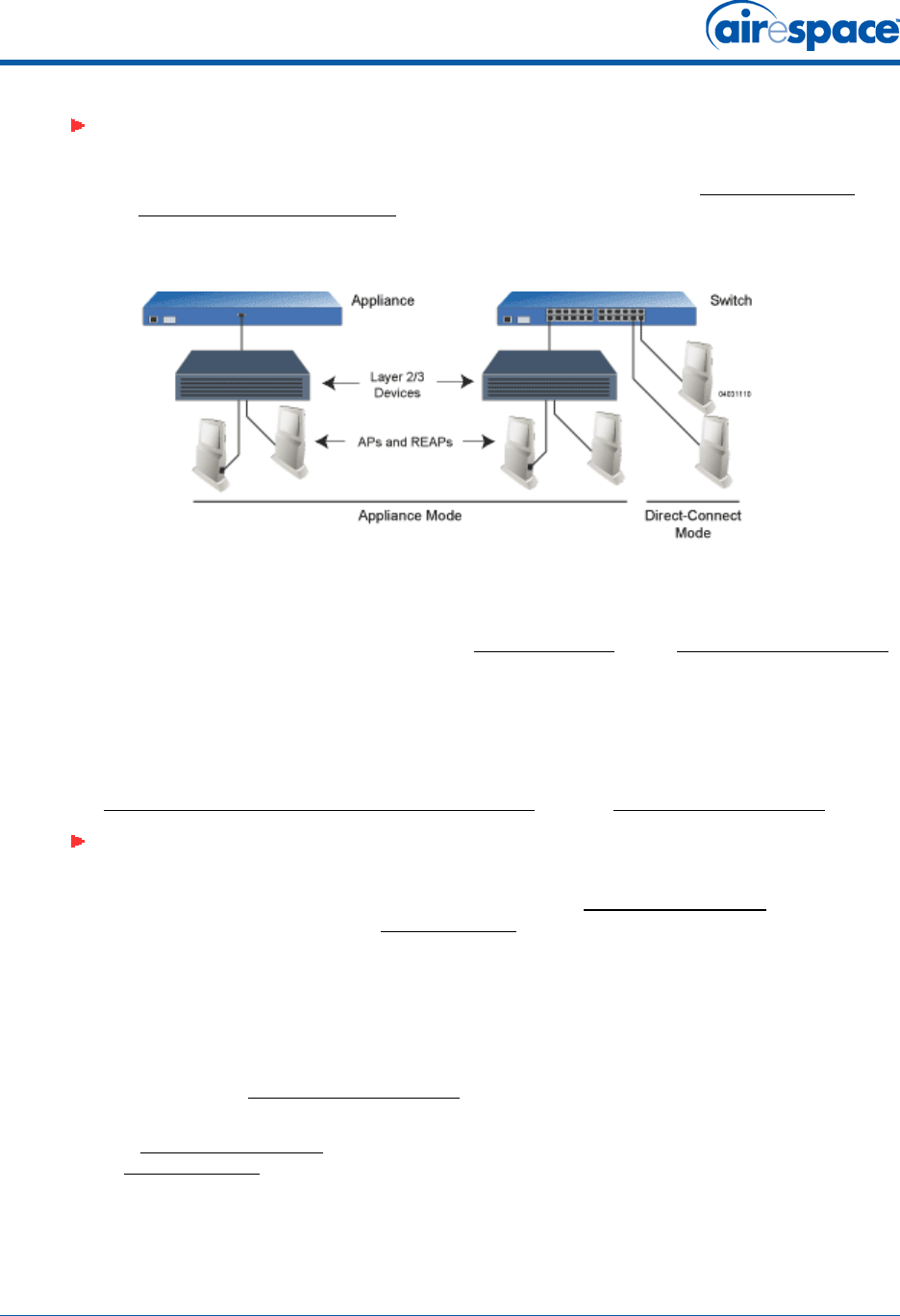
-Make sure Airespace AP ports are available (either Direct-Connect Mode through the
Switch physical ports, or in Appliance Mode through the Airespace Switch or Appliance
Management/AP-Manager Interface).
-Set the Airespace Switch or Appliance as the Master, so new Airespace APs always
associate with it. Use the CLI command show network config to determine if the
Airespace Switch or Appliance DS Port is the Master. If it is not, make it the Master with
the CLI command properly, make sure to use the CLI command config network
master-base disable.
-Refer to the Airespace Product Guide for other settings.
2. Take the Airespace AP or REAP out of the box and plug it into the front panel of the Master
Switch (Direct-Connect Mode), or through the same subnet that Airespace Switch or Appliance
is on (Appliance Mode).
3. Apply power to the Airespace AP:
-Use 802.3af-compatible Power Over Ethernet (PoE) from the Airespace Switch or
Appliance or from an orderable inline power injector. If you do not have PoE available,
Note: This procedure assumes that you are preparing a version 2.0 Airespace AP or
REAP to interoperate with a version 2.0 Airespace Switch or Appliance. When you are
preparing a version 1.2 Airespace AP to interoperate with a version 1.2 Airespace
Switch or Appliance, use the procedure found in the version 1.2 Airespace Access
Point Quick Installation Guide.
Note: When you are installing a REAP or an Airespace AP, a DHCP server must be
accessible by the REAP or an Airespace AP.
11/16/04 Preparing a Version 2.0 Airespace AP or REAP
90-100906-000 Rev 1 9
use an orderable external AC-to-48 VDC Power Supply plugged into the side of the
Airespace AP.
-After powering up the Airespace AP, the RED Alarm LED comes on for a short period
(about 15-20 seconds) and then all the LEDs blink sequentially back and forth,
indicating that the Airespace AP is trying to find an Airespace Switch or Appliance to
connect to. This can continue for up to five minutes. If the Airespace AP remains in this
mode for more than five minutes, the Airespace AP is unable to find the Master
Airespace Switch or Appliance. Check the connection between the Airespace AP and the
Airespace Switch or Appliance and make sure the Airespace AP and the Airespace
Switch or Appliance are on the same subnet.
-If the power light does not come on, check the power (it can be powered either with
Power over Ethernet or a from an orderable Airespace AP External Power Supply.
-Make sure that a DHCP server is configured in the Airespace Switch or Appliance for
both the Management Interface and AP-Manager Interface using the CLI, Web Browser,
or ACS interface, and that the DHCP server is operating correctly.
-Once the Airespace AP finds the Airespace Switch or Appliance, it attempts to download
the new Airespace Operating System code if the Airespace AP code version differs from
the Airespace Switch or Appliance code version. While this is happening, the LEDs on
the top of the Airespace AP blink on and off together.
4. Once the Airespace Operating System code download is successful, the Airespace AP reboots.
The GREEN LED turns on and the two YELLOW LEDs indicate the states of the 802.11a and
802.11b/g networks. If any part of the network is disabled in the Airespace Switch or Appli-
ance, the corresponding YELLOW LED remains off.
-Note that the Red LED can light for a short period (10-20 seconds) when the Airespace
AP reboots. If the RED LED comes on AND STAYS ON for more than a minute,
disconnect the Airespace AP and call Airespace Global Services & Support.
-Use the CLI command show ap summary. If the new Airespace AP appears on the list, it
has been configured successfully.
-From the CLI, Web Browser or ACS interface, configure the Airespace AP with its
Primary, Secondary and Tertiary Airespace Switch or Appliance names as described in
the Airespace Product Guide.
-If you will be using the Airespace AP in a mobility or a WPS group, set the mobility or
WPS group name using the CLI, Web Browser or ACS interface.
-If required, use the CLI, Web Browser or ACS interface to customize the Airespace
AP-specific 802.11a, 802.11b and 802.11g network settings. Once again, the two
YELLOW LEDs indicate the states of the 802.11a and 802.11b/g networks. If any part of
the network is disabled, the corresponding YELLOW LED remains off.
5. If everything works (the GREEN LED is on and the RED LED is off), disconnect the Airespace AP
and take it to its final destination and install it as described in this document. If your Airespace
AP fails this visual test, refer to RMA Procedures in the Airespace Product Guide to return your
Airespace APs.
11/16/04 Alternate Preparing a Version 2.0 Airespace AP or REAP
90-100906-000 Rev 1 10
6. When you have installed and powered up the Airespace AP or REAP in its final destination,
verify that the LEDs are in the same state they were in at the end of Step 4.
-If no LEDs are on, the Airespace AP is most likely not receiving power.
-If the LEDs blink sequentially back and forth for more than five minutes, the Airespace
AP is unable to find its Primary, Secondary or Tertiary Airespace Switch or Appliance.
Check the connection between the Airespace AP and the Airespace Switch or Appliance,
and make sure the Airespace AP and the Airespace Switch or Appliance are either on
the same subnet or that the Airespace AP has a route back to its Primary, Secondary
and Tertiary Airespace Switches and Appliances.
-If the Airespace AP is not on the same subnet as the Airespace Switch or Appliance,
make sure there is a DHCP server on the same subnet as the Airespace AP. Also, make
sure that the route between the Airespace AP and the Airespace Switch or Appliance
can process IP fragmented packets.
After you have prepared all Airespace APs, reconfigure the Airespace Switch or Appliance so it is not the
Master. A Master Airespace Switch or Appliance should only be used for configuring Airespace APs and
not in a working network. Note that the Master Airespace Switch or Appliance is normally not used in a
deployed network, so the Master Airespace Switch or Appliance setting is automatically disabled upon
reboot or AireOS code upgrade.
After completing Step 2: Configuring the Airespace AP or REAP Before Installation for all Airespace APs
and REAPs, continue with Step 3: Preparing Mounting Locations.
Alternate Preparing a Version 2.0 Airespace AP or REAPAlternate Preparing a Version 2.0 Airespace AP or REAP
If your Airespace AP has Airespace Operating System 2.0 or a later version (which includes all REAPs)
loaded on it, you may choose to use this procedure. If your Airespace AP has Airespace Operating
System 1.2 or earlier loaded on it, or if you do not know what version the Airespace AP has loaded, use
the Preparing a Version 1.2 Airespace AP procedure above.
When you are preparing a version 1.2 Airespace AP to interoperate with a version 1.2 Airespace Switch
or Appliance, use the procedure found in the version 1.2 Airespace Access Point Quick Installation
Guide.
Note: When you are installing a REAP or a Layer 3 Airespace AP on a different subnet
than the Airespace Switch or Appliance, MAKE SURE that a DHCP server is available
on the subnet where you will be installing the Airespace AP or REAP, and that the
subnet has a route back to the Airespace Switch or Appliance. Also make sure that
the route back to the Airespace Switch or Appliance has destination UDP ports 12222
and 12223 open for LWAPP communications. Ensure the route back to the Primary,
Secondary and Tertiary Airespace Switches or Appliances allows IP packet frag-
ments. Finally, make sure that if address translation is used, that the Airespace AP
and the Airespace Switch or Appliance have a static 1-to-1 NAT to an outside
address. (Port Address Translation is not supported.)
Note: This procedure assumes that you are preparing a version 2.0 Airespace AP or
REAP to interoperate with a version 2.0 Airespace Switch or Appliance. It also
assumes that your Airespace Switch or Appliance is already operating in LWAPP
Layer 3 Mode. It also assumes that you are using the Internet Software Consortium
(ISC) DHCP Server V3.0pl1. Finally, it assumes that if you have deployed multiple
Airespace Switches and Appliances, that the Airespace Switch or Appliance you use
to initialize the Airespace AP is in an existing Airespace Mobility Group with the
Primary, Secondary, and Tertiary Airespace Switch or Appliance you want to assign
to the new Airespace AP or REAP.
11/16/04 Alternate Preparing a Version 2.0 Airespace AP or REAP
90-100906-000 Rev 1 11
Configuration SetupConfiguration Setup
Does My Airespace AP Qualify for this Procedure?Does My Airespace AP Qualify for this Procedure?
•If your 2.0 or later version later Airespace AP(s) or REAP(s) cannot be configured for any
reason using the following procedure, refer to RMA Procedures in the Airespace Product Guide.
Configuration Steps for an Airespace AP or REAPConfiguration Steps for an Airespace AP or REAP
1. Configure the Internet Software Consortium (ISC) V3.0pl1 DHCP Server to provide the ven-
dor-specific Option 43 using the following entries:
option controller code 43 = text;
option controller “<Switch IP Address>”;
in which <Switch IP Address> is the IP address of the Airespace Switch or Appliance you are
going to use to prepare the Airespace AP or REAP, or which can be a comma-delimited string of
Airespace Switch or Appliance IP addresses.
(These commands direct all unconfigured Airespace APs and REAPs discovery messages to the
configuring Airespace Switch or Appliance.)
2. Make sure the configuring Airespace Switch or Appliance is in LWAPP Layer 3 Mode (use the
CLI command show switchconfig to determine the mode; if it is set to layer 3, use the CLI
command config switchconfig mode L2 to change it to Layer 2). Make sure that the configuring
Airespace Switch or Appliance is in the same mobility group as the planned Primary, Secondary,
and Tertiary Airespace Switch or Appliance, and that the configuring Airespace Switch or Appli-
ance DS Port is connected to the network. Use CLI, Web Browser and/or ACS procedures as
described in the Airespace Switch or Appliance Quick Install Guide and the Airespace Product
Guide.
3. Also make sure that the DHCP server is configured in the Airespace Switch or Appliance for both
the Management Interface and AP-Manager Interface using the CLI, Web Browser, or ACS user
interface.
4. Take the Airespace AP or REAP out of the box and plug it into the network so that it can request
an IP address from the DHCP server.
5. Apply power to the Airespace AP:
-Use 802.3af-compatible Power Over Ethernet (PoE) from the Airespace Switch or
Appliance or from an orderable inline power injector. If you do not have PoE available,
Note: When you are installing a REAP or an Airespace AP, a DHCP server must be
accessible by the REAP or an Airespace AP.
11/16/04 Alternate Preparing a Version 2.0 Airespace AP or REAP
90-100906-000 Rev 1 12
use an orderable AC-to-48 VDC External Power Supply plugged into the side of the
Airespace AP.
-After powering up the Airespace AP, the RED Alarm LED comes on for a short period
(about 15-20 seconds) and then all the LEDs blink sequentially back and forth,
indicating that the Airespace AP is trying to find an Airespace Switch or Appliance to
connect to. This can continue for up to five minutes. If the Airespace AP remains in this
mode for more than five minutes, the Airespace AP is unable to find the Master
Airespace Switch or Appliance. Check the connection between the Airespace AP and the
Airespace Switch or Appliance and make sure the Airespace AP and the Airespace
Switch or Appliance are on the same subnet.
-If the power light does not come on, check the power (it can be powered either with
Power over Ethernet or a from an orderable Airespace AP External Power Supply.
6. The Airespace AP or REAP requests an IP address from the DHCP server, and the DHCP server
returns an IP address for the Airespace AP or REAP, and also returns the <Switch IP Address>
of the configuring Airespace Switch or Appliance.
Once the Airespace AP or REAP finds the configuring Airespace Switch or Appliance, it attempts
to download the new Airespace Operating System code if the Airespace AP code version differs
from the configuring Airespace Switch or Appliance code version. While this is happening, the
LEDs on the top of the Airespace AP or REAP blink on and off together.
7. Once the Airespace Operating System code download is successful, the Airespace AP or REAP
reboots. The GREEN LED turns on and the two YELLOW LEDs indicate the states of the 802.11a
and 802.11b/g networks. If any part of the network is disabled in the configuring Airespace
Switch or Appliance, the corresponding YELLOW LED remains off.
-Note that the Red LED can light for a short period (10-20 seconds) when the Airespace
AP or REAP reboots. If the RED LED comes on AND STAYS ON for more than a minute,
disconnect the Airespace AP or REAP and call Airespace Global Services & Support.
-From the CLI, Web Browser or ACS interface, configure the Airespace AP with its
Primary, Secondary and Tertiary Airespace Switch or Appliance names (any of which
can be the name of the configuring Airespace Switch or Appliance) as described in the
Airespace Product Guide.
-If required, use the CLI, Web Browser or ACS interface to customize the Airespace AP-
or REAP-specific 802.11a, 802.11b and 802.11g network settings. Once again, the two
YELLOW LEDs indicate the states of the 802.11a and 802.11b/g networks. If any part of
the network is disabled, the corresponding YELLOW LED remains off.
8. If everything works (the GREEN LED is on and the RED LED is off), reboot the Airespace AP or
REAP and install it as described in this document. If your Airespace AP or REAP fails this visual
test, refer to RMA Procedures in the Airespace Product Guide to return your Airespace APs.
Note: When you are installing a REAP or a Layer 3 Airespace AP on a different subnet
than the Airespace Switch or Appliance, MAKE SURE that a DHCP server is available
on the subnet where you will be installing the Airespace AP or REAP, and that the
subnet has a route back to the Primary, Secondary and Tertiary Airespace Switches
or Appliances. Also make sure that the route back to the Airespace Switch or
Appliance has destination UDP ports 12222 and 12223 open for LWAPP communica-
tions. Ensure the route back to the Primary, Secondary and Tertiary Airespace
Switches or Appliances allows IP packet fragments. Finally, make sure that if address
translation is used, that the Airespace AP and the Airespace Switch or Appliance have
a static 1-to-1 NAT to an outside address. (Port Address Translation is not
supported.)
11/16/04 Alternate Preparing a Version 2.0 Airespace AP or REAP
90-100906-000 Rev 1 13
9. When you have installed and powered up the Airespace AP or REAP in its final destination,
verify that the LEDs are in the same state they were in at the end of Step 7.
-If no LEDs are on, the Airespace AP is most likely not receiving power.
-If the LEDs blink sequentially back and forth for more than five minutes, the Airespace
AP is unable to find its Primary, Secondary or Tertiary Airespace Switches or
Appliances. Check the connection between the Airespace AP and the Airespace Switch
or Appliance, and make sure the Airespace AP and the Airespace Switch or Appliance
are either on the same subnet or that the Airespace AP has a route back to its Primary,
Secondary and Tertiary Airespace Switches and Appliances.
-Note that the REAPs at each remote location must be on the same subnet to allow client
roaming. Also, if the Airespace AP or REAP is not on the same subnet as the Airespace
Switch or Appliance, make sure that a DHCP server is accessible on the same subnet as
the Airespace AP or REAP.
After completing Step 2: Configuring the Airespace AP or REAP Before Installation for all Airespace APs
and REAPs, continue with Step 3: Preparing Mounting Locations.
11/16/04 Step 3: Preparing Mounting Locations
90-100906-000 Rev 1 14
Step 3: Preparing Mounting LocationsStep 3: Preparing Mounting Locations
On your map, you should have the Airespace AP locations, mounting options, and power options.
•Find the required mounting locations.
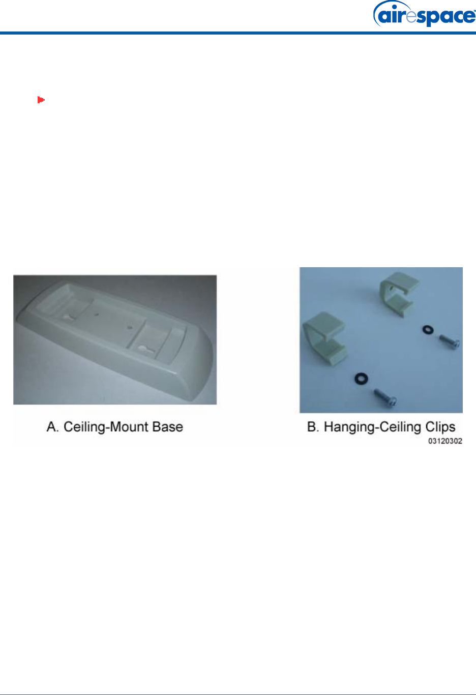
•Use the ceiling-mount base to mark the wall or ceiling locations for sheet metal, drywall, or
other screws. Make sure you leave enough space around the Airespace AP and base to plug the
CAT-5 cable, optional external antenna cable(s), optional power supply cable, and optional
Kensington MicroSaver Security Cable into the sides of the Airespace AP.
Figure - Factory-Supplied Mounting Options
•Alternatively, attach the hanging ceiling clips to the Airespace AP. Make sure you leave enough
space around the Airespace AP to plug the CAT-5 cable, optional external antenna cable(s),
optional power supply cable, and optional Kensington MicroSaver Security Cable into the sides
of the Airespace AP.
•Alternatively, use the optional mounting bases and/or brackets to mark the wall or ceiling
locations for sheet metal, drywall, or other screws. Make sure you leave enough space around
the Airespace AP and brackets to plug the CAT-5 cable, optional external antenna cable(s),
optional power supply cable, and optional Kensington MicroSaver Security Cable into the sides
of the Airespace AP.
Note: MAKE SURE that plenum-mounted Airespace APs and REAPs use only the
metal Projection-Mount and Flush-Mount brackets (not the Ceiling-Mount Base or the
Hanging-Ceiling Clips) and are powered using Power Over Ethernet (POE) to comply
with safety regulations.
Also, external antennas are NOT to be used when installing Airespace APs and REAPs
in a plenum.
11/16/04 Step 3: Preparing Mounting Locations
90-100906-000 Rev 1 15
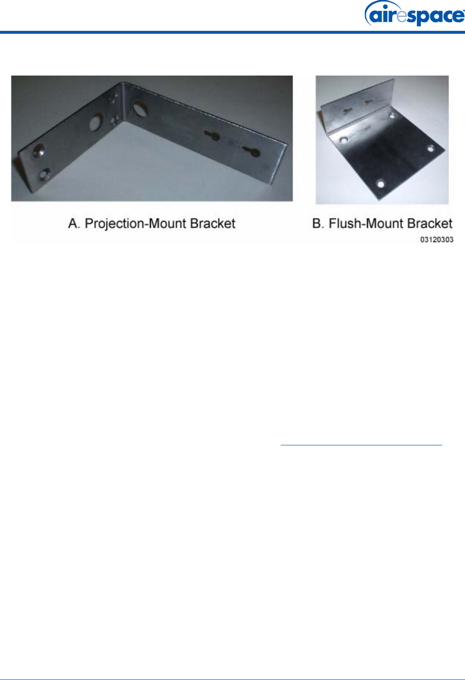
Figure - Factory-Orderable Mounting Brackets
•If necessary, drill holes for the various cables where they can be mostly hidden from casual
view. When you are mounting the Airespace AP using an optional separately-orderable
projection-mount L-bracket (the one with two long legs), the cables can be routed through the
5/8-inch (15.9 mm) holes in the bracket.
•Route the CAT-5, optional power supply, optional external antenna cable(s), and optional
Kensington MicroSaver Security cables to where they can plug into the Airespace AP. Make sure
to leave about 6 inches (15 cm) of slack in the cables for future modifications.
•Attach the brackets to the wall or ceiling, or install screws for ceiling-mount base:
-Where you are going to use the projection-mount or flush-mount bracket, use
customer-supplied sheet metal, drywall, or other screws to attach the bracket to the
ceiling or wall.
-Where you are going to use the ceiling-mount base, install customer-supplied sheet
metal, drywall, or other screws with 1/4 inch (6.35 mm) or smaller heads protruding
from the ceiling about 0.1 inch (2.5 mm).
You are now ready to install the Airespace APs. Continue with Step 4: Mounting the Airespace APs.
11/16/04 Step 4: Mounting the Airespace APs
90-100906-000 Rev 1 16
Step 4: Mounting the Airespace APsStep 4: Mounting the Airespace APs
Using the supplied or optional separately-orderable Airespace AP mounting kits, mount each Airespace
AP in its indicated location, oriented as shown on the map. Note that you can mount the Airespace APs
in the ceiling plenum or below the ceiling, but the Airespace APs perform best when mounted below the
ceiling.
Note that the Airespace System supports Antenna Sectorization, which can be used to increase the
number of clients and/or client throughput in a given air space. Installers can mount two Airespace APs
back-to-back and the Airespace System operator can disable the second antenna in both Airespace APs
to create a 360-degree coverage area with two sectors.
The Airespace APs can be mounted in one of the following configurations:
•Ceiling-Mount Base -- Refer to Ceiling Mount Base.
•Ceiling-Mount Clips -- Refer to Ceiling-Mount Clips.
•Projection Wall Mount -- Refer to Projection Wall Mount.
•Flush Wall Mount -- Refer to Flush Wall Mount.
•Ceiling-Mount Bezel -- Refer to the Airespace AP Ceiling-Mount Bezel Kit Quick Installation
Guide.
Ceiling Mount BaseCeiling Mount Base
When you are mounting the Airespace AP in the middle of a ceiling (flat sides toward the room or
hallway), use the ceiling-mount base to mount the Airespace AP as shown in the following figure and as
described below:
11/16/04 Step 4: Mounting the Airespace APs
90-100906-000 Rev 1 17
Figure - Assembling the Airespace AP and Ceiling-Mount Base
•Copy the MAC address(es) from the label(s) on the Airespace AP onto the corresponding
location on the map. MAC addresses have the format 000B85xxxxxx.
•Attach the ceiling-mount base to the bottom of the Airespace AP using the factory-supplied
machine screws and washers.
•Position the ceiling-mount base so its keyhole slots are partly on the drywall, sheet metal, or
other screw heads installed in Step 3: Preparing Mounting Locations.
•Attach the cables to the sides of the Airespace AP.
Note: If the screws do not securely hold the ceiling-mount base, remove the
Airespace AP and adjust the screws until they hold the ceiling-mount base securely.
Note: When the Airespace AP is powered up and is associated with an Airespace
Switch or Appliance (Green/Power and Yellow/802.11b/g and/or Yellow or Amber/
802.11a LEDs lit), the Airespace AP is broadcasting its beacon signal(s). When this
happens, complete the installation as quickly as possible to remove yourself from
within 8 inches (20 cm) of the Airespace AP to comply with FCC RF radiation
exposure guidelines.
11/16/04 Step 4: Mounting the Airespace APs
90-100906-000 Rev 1 18
•Slide the ceiling-mount base onto the drywall, sheet metal, or other screw heads until it snugs
into place.
You have installed the Airespace AP. Repeat Step 4: Mounting the Airespace APs for each Airespace AP
location, and then continue with Step 5: Returning MAC Information.
Ceiling-Mount ClipsCeiling-Mount Clips
When you are mounting the Airespace AP on the extruded aluminium rails of a hanging ceiling, use the
ceiling-mount clips to mount the Airespace AP as shown in the following figure and as described below:
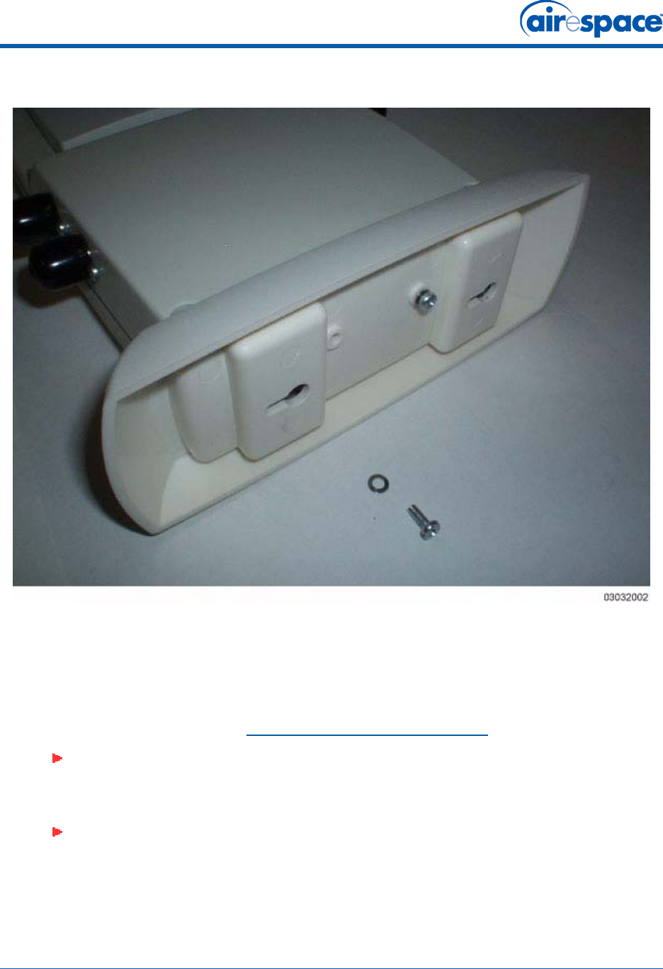
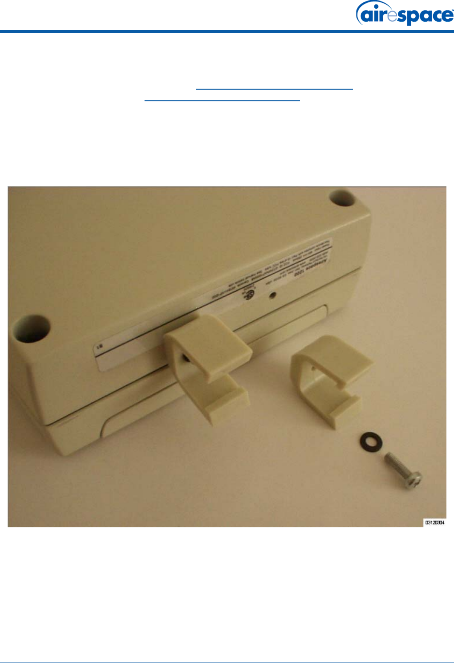
Figure - Assembling the Airespace AP and Ceiling-Mount Clips
•Copy the MAC address(es) from the label(s) on the Airespace AP onto the corresponding
location on the map. MAC addresses have the format 000B85xxxxxx.
•Attach the ceiling-mount clips to the bottom of the Airespace AP using the factory-supplied
machine screws and washers.
•Snap the ceiling-mount clips onto a hanging ceiling rail.
11/16/04 Step 4: Mounting the Airespace APs
90-100906-000 Rev 1 19
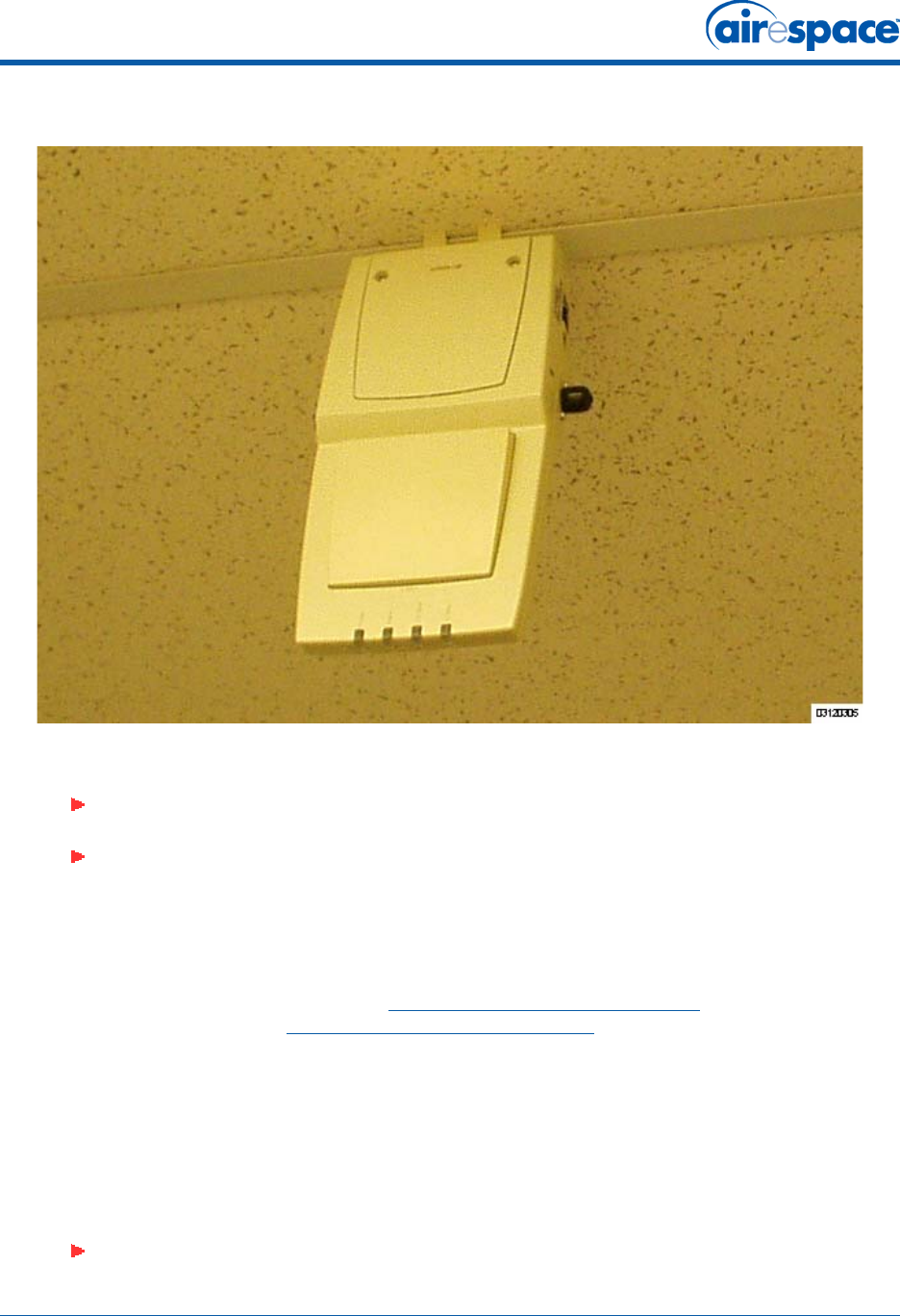
Figure - Clipping the Airespace AP and Ceiling-Mount Clips to a Hanging-Ceiling Rail
•Attach the cables to the sides of the Airespace AP.
You have installed the Airespace AP. Repeat Step 4: Mounting the Airespace APs for each Airespace AP
location, and then continue with Step 5: Returning MAC Information.
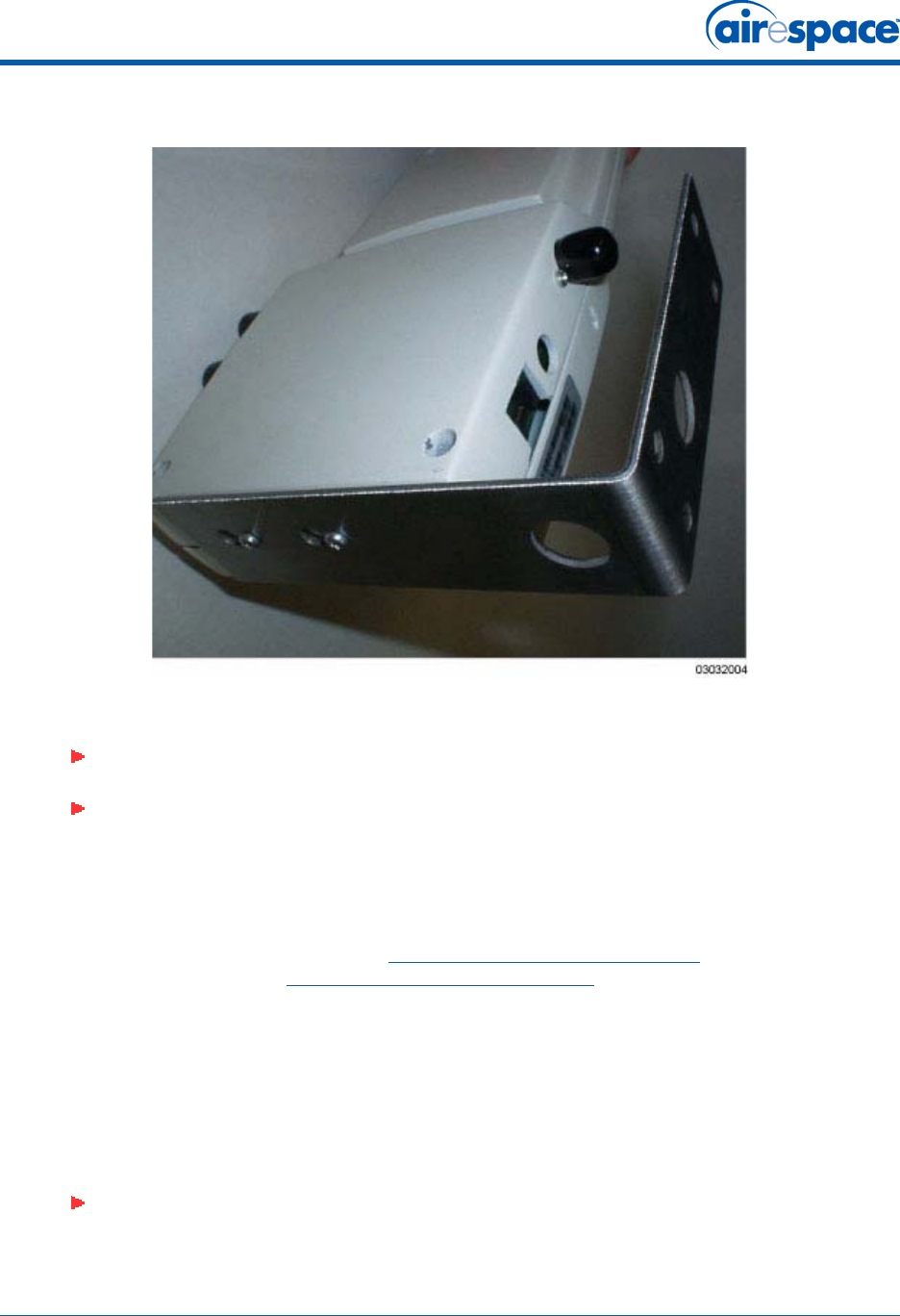
Projection Wall MountProjection Wall Mount
When you are mounting the Airespace AP out from a wall (flat sides along the wall or hallway), use an
optional separately-orderable factory-orderable projection-mount L-bracket.
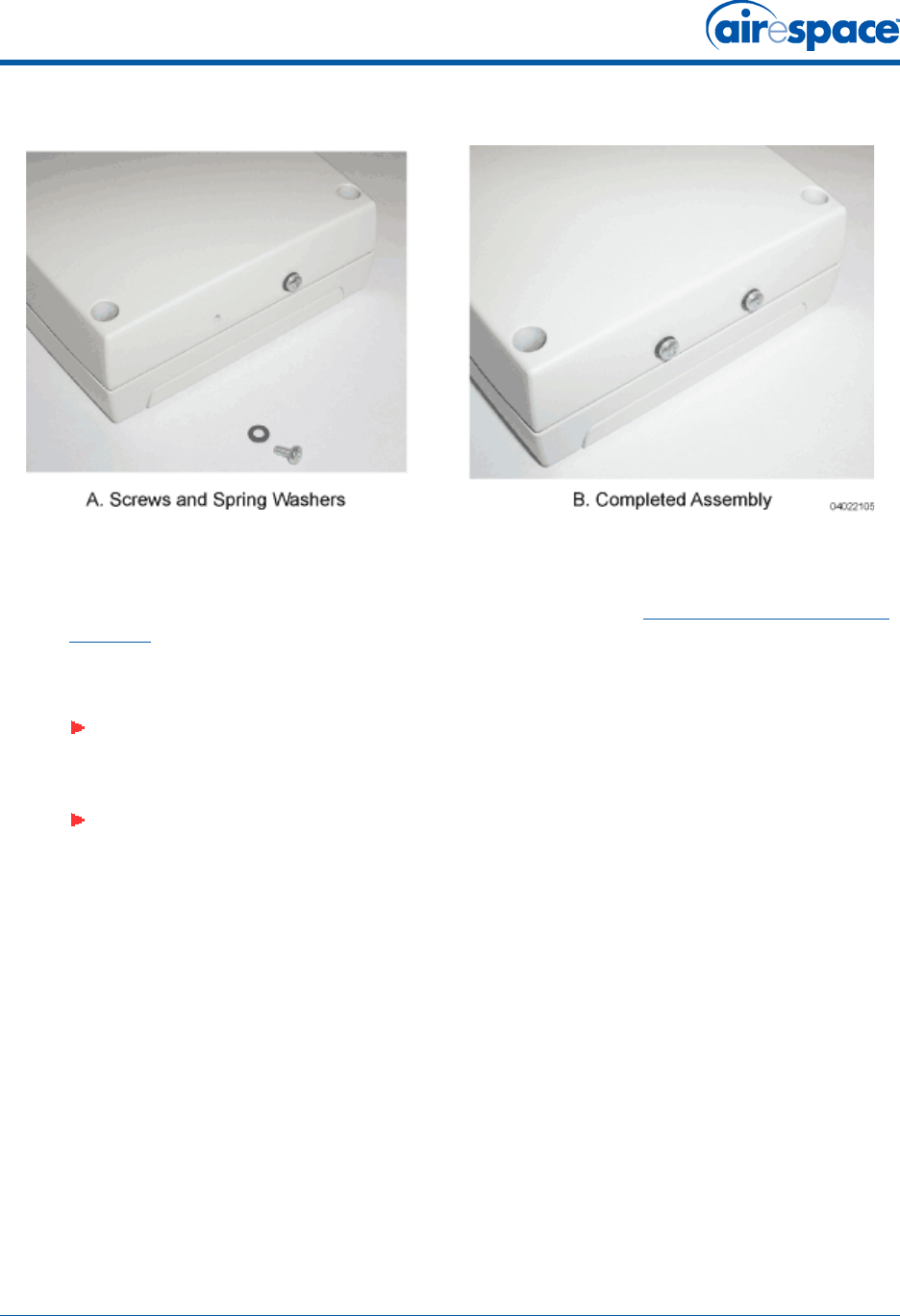
•Before proceeding, gently screw the two factory-supplied screws and spring washers into the
bottom of the Airespace AP. Make sure the spring washers have their convex (high center
sections) pointing toward the screw heads.
Note: Make sure the cables are routed away from the Airespace AP antennas.
Note: When the Airespace AP is powered up and is associated with an Airespace
Switch or Appliance (Green/Power and Yellow/802.11b/g and/or Yellow or Amber/
802.11a LEDs lit), the Airespace AP is broadcasting its beacon signal(s). When this
happens, complete the installation as quickly as possible to remove yourself from
within 8 inches (20 cm) of the Airespace AP to comply with FCC RF radiation
exposure guidelines.
Note: The Airespace AP threaded holes have precision-depth threads. Do not over-
tighten the screws, or the bracket will not fit under the screw heads.
11/16/04 Step 4: Mounting the Airespace APs
90-100906-000 Rev 1 20
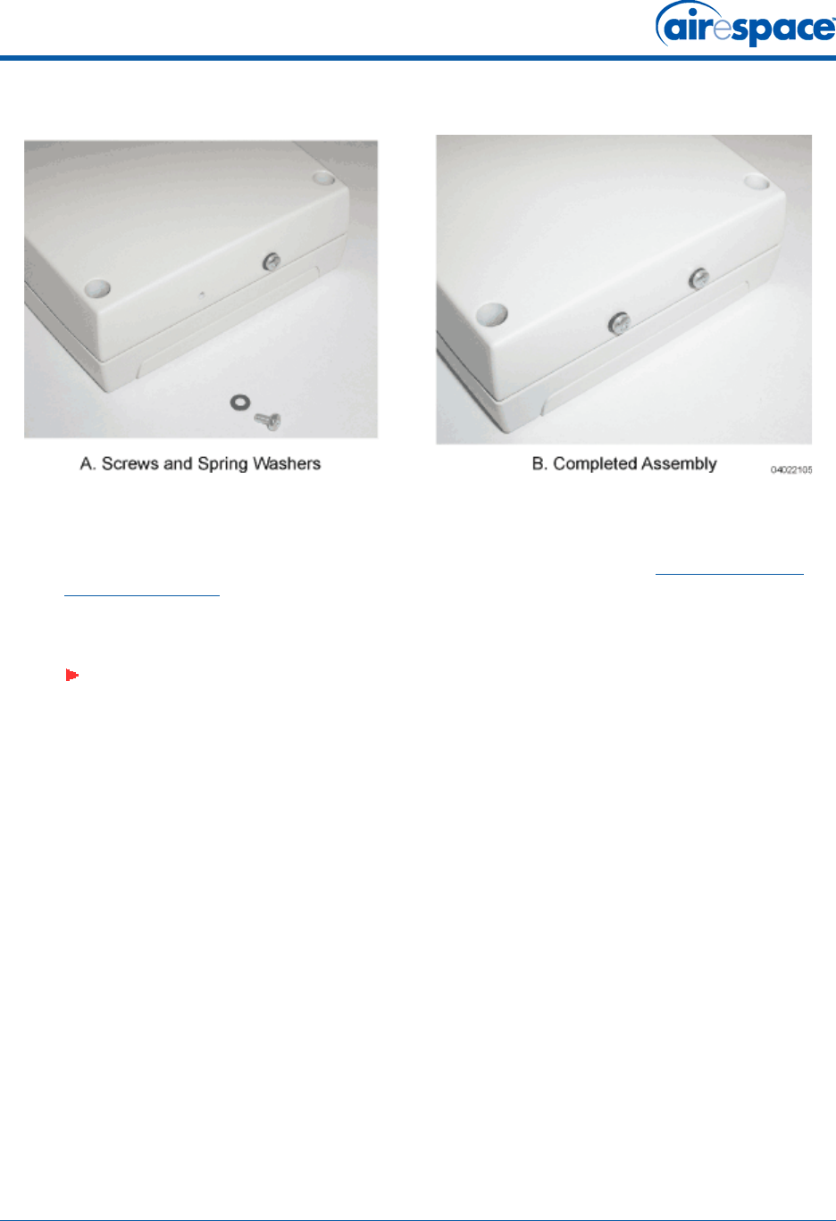
Figure - Assembling the Mounting Screws and Spring Washers to the Airespace AP
•Copy the MAC address(es) from the label(s) on the Airespace AP onto the corresponding
location on the map. MAC addresses have the format 000B85xxxxxx.
•You have already attached the projection-mount L-bracket to the wall in Step 3: Preparing
Mounting Locations.
•Slide the screws into the keyhole slots on the mounting bracket as shown in the following
figure.
Note: If the screws do not securely hold the bracket, remove the Airespace AP and
adjust the screws until they securely hold the bracket.
11/16/04 Step 4: Mounting the Airespace APs
90-100906-000 Rev 1 21
Figure - Assembling the Airespace AP to the Projection-Mount Bracket
•Attach the cables to the sides of the Airespace AP.
You have installed the Airespace AP. Repeat Step 4: Mounting the Airespace APs for each Airespace AP
location, and then continue with Step 5: Returning MAC Information.
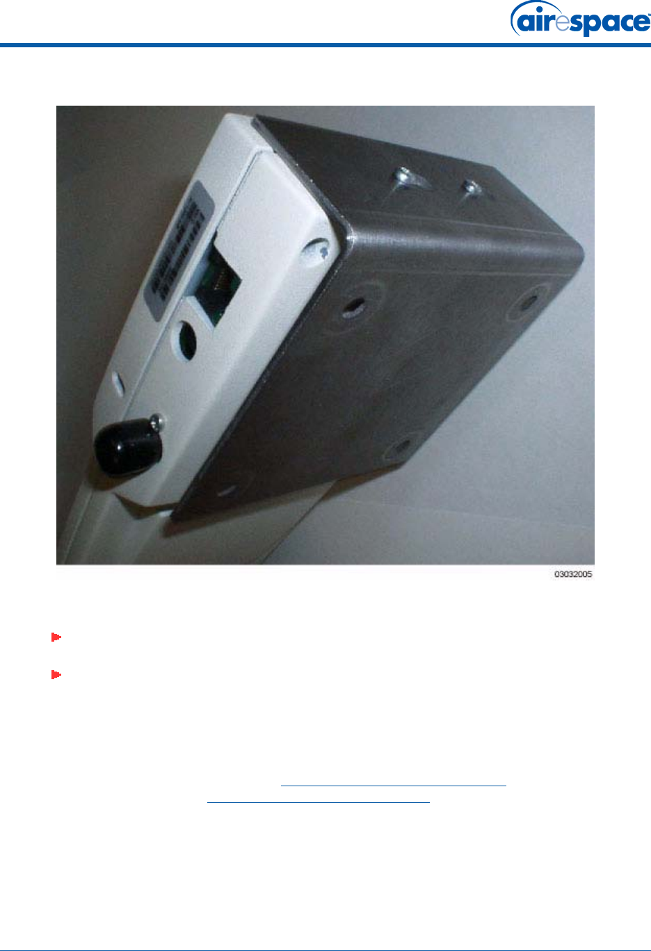
Flush Wall MountFlush Wall Mount
When you are mounting the Airespace AP against a wall (flat side toward the inside of the building), use
an optional separately-orderable factory-orderable flush-mount bracket.
•Before proceeding, gently screw the two factory-supplied screws and spring washers into the
bottom of the Airespace AP. Make sure the spring washers have their convex (high center
sections) pointing toward the screw heads.
Note: Make sure the cables are routed away from the Airespace AP antennas.
Note: When the Airespace AP is powered up and is associated with an Airespace
Switch or Appliance (Green/Power and Yellow/802.11b/g and/or Yellow or Amber/
802.11a LEDs lit), the Airespace AP begins broadcasting its beacon signal(s). When
this happens, complete the installation as quickly as possible to remove yourself
from within 8 inches (20 cm) of the Airespace AP to comply with FCC RF radiation
exposure guidelines.
Note: The Airespace AP threaded holes have precision-depth threads. Do not over-
tighten the screws, or the bracket will not fit under the screw heads.
11/16/04 Step 4: Mounting the Airespace APs
90-100906-000 Rev 1 22
Figure - Assembling the Mounting Screws and Spring Washers to the Airespace AP
•Copy the MAC address(es) from the label(s) on the Airespace AP onto the corresponding
location on the map. MAC addresses have the format 000B85xxxxxx.
•You have already attached the flush-mount bracket to the wall in Step 3: Preparing Mounting
Locations.
•Slide the screws into the keyhole slots on the mounting bracket as shown in the following
figure.
Note: Make sure the side of the Airespace AP with the door is facing away from the
wall. This ensures that the correct antenna is facing the building, and makes future
upgrades easier.
Note: If the screws do not securely hold the bracket, remove the Airespace AP and
adjust the screws until they securely hold the bracket.
11/16/04 Step 4: Mounting the Airespace APs
90-100906-000 Rev 1 23
Figure - Assembling the Airespace AP to the Flush-Mount Bracket
•Attach the cables to the sides of the Airespace AP.
You have installed the Airespace AP. Repeat Step 4: Mounting the Airespace APs for each Airespace AP
location, and then continue with Step 5: Returning MAC Information.
Note: Make sure the cables are routed away from the Airespace AP antennas.
Note: When the Airespace AP is powered up and is associated with an Airespace
Switch or Appliance (Green/Power and Yellow/802.11b/g and/or Yellow or Amber/
802.11a LEDs lit), the Airespace AP begins broadcasting its beacon signal(s). When
this happens, complete the installation as quickly as possible to remove yourself
from within 8 inches (20 cm) of the Airespace AP to comply with FCC RF radiation
exposure guidelines.

11/16/04 Step 5: Returning MAC Information
90-100906-000 Rev 1 24
Step 5: Returning MAC InformationStep 5: Returning MAC Information
When you have completed the installations as outlined in Step 4: Mounting the Airespace APs, return
the MAC addresses and their locations on the maps or floor plans to the network planner or manager.
The Airespace Control System Software (ACS Software) operators will use the MAC address and
location information to create maps for precise wireless Airespace Operating System management.
Also return any unused mounting kit hardware and external power supplies to the network planner or
manager for use in future deployments.
Note: Please remind the Network Planner or Manager that now is a good time to
register the Airespace APs.
11/16/04 Planning Notes
90-100906-000 Rev 1 25
Planning NotesPlanning Notes
•About Cables
•About External Antennas
•About Mounting Options
•About Physical Security
•FCC Statements for Airespace APs
•Industry Canada Required User Information for Airespace APs
•Safety Considerations
About CablesAbout Cables
•You will run one CAT-5 Ethernet cable from the Airespace AP to the Airespace WLAN Switch,
another network device, or a PoE injector/hub.
When the Airespace AP will be mounted below the ceiling using the ceiling mount or wall mount
brackets, you may have to drill a hole into the ceiling plenum to run the CAT-5 cable to the wir-
ing closet. When the CAT-5 cable cannot be run through the ceiling plenum, find another path
to route the cable from the Airespace AP to the wiring closet.
When the Airespace AP will be mounted above the ceiling using the ceiling mount or wall mount
brackets, run the CAT-5 cable to the wiring closet through the ceiling plenum. When the CAT-5
cable cannot be run through the ceiling plenum, find another path to route the cable from the
Airespace AP to the wiring closet.
•When you are powering the Airespace AP from AC power, route the power supply cable from
the AC electrical outlet to the Airespace AP. Make sure you secure the AC power plug so it will
be difficult for people to pull on the power cord or unplug the power supply from the AC power
outlet.
•When you are powering the Airespace AP from a PoE source (Airespace WLAN Switch, another
network device, or a PoE injector/hub), you do not need to route a separate power cable to the
Airespace AP, because the Airespace AP will receive its power across the CAT-5 Ethernet cable.
Return the power supply to the wireless network planner/manager.
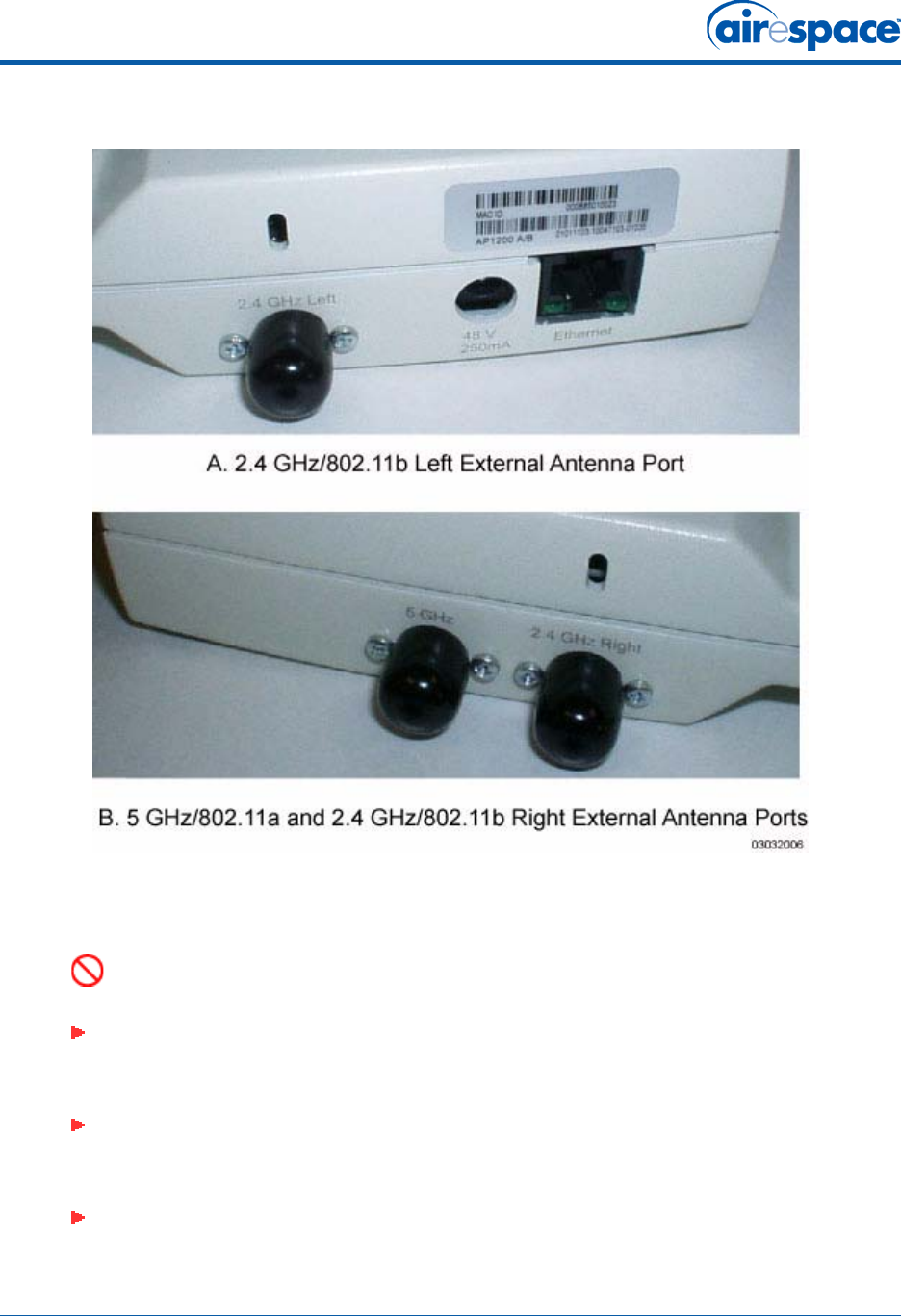
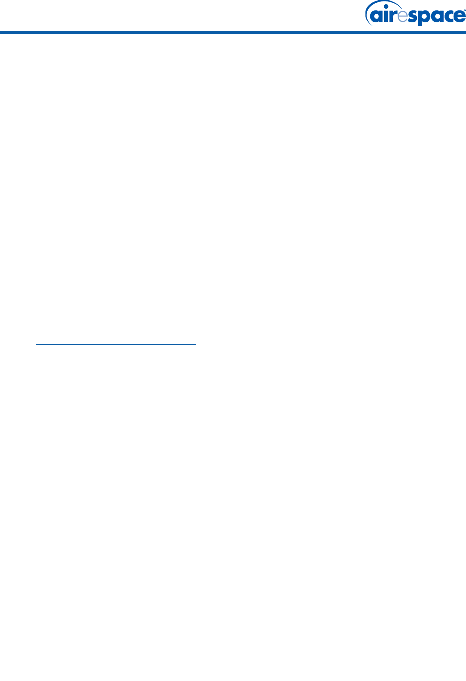
About External AntennasAbout External Antennas
•Refer to the Airespace AP External and Internal Antennas section in the Airespace Product
Guide for an overview of the external 802.11a and 802.11b/g external antennas usable with
the Airespace APs.
•When you are attaching external antennas to the AS-1200-A-EXT, AS-1200-BG-EXT, or
AS-1200-ABG-EXT Airespace AP, use cables with female reverse-TNC connectors to connect
antennas to the ports on the side of the Airespace AP. See the following figure for antenna port
markings.
Note: As described in the Internal-Antenna Airespace Access Point Quick Installation
Guide, the AS-1200-BG-INT and AS-1200-ABG-INT Airespace APs are designed to be
used exclusively with the internal high-gain antennas, and have no jacks for external
antennas.
Note: External antennas are NOT to be used when installing Airespace APs and
REAPs in a plenum.
11/16/04 Planning Notes
90-100906-000 Rev 1 26
Figure - Airespace AP External Antenna Port Markings
About Mounting OptionsAbout Mounting Options
DANGER: Plenum-mounted Airespace APs and REAPs MUST BE powered using
Power Over Ethernet (POE) to comply with safety regulations.
Note: Because the Airespace AP internal antennas have been designed to reduce
inter-floor interference, it is strongly recommended that you mount the Airespace AP
standing or hanging straight up or down.
Note: You can mount the Airespace APs in the ceiling plenum or below the ceiling
using the ceiling mount base or wall mount brackets, but the Airespace APs perform
best when mounted below the ceiling.
Note: External antennas are NOT to be used when installing Airespace APs and
REAPs in a plenum.
11/16/04 FCC Statements for Airespace APs
90-100906-000 Rev 1 27
•When you are mounting the Airespace AP in the middle of a ceiling, ceiling plenum, or hallway,
you will typically use the color-coordinated ceiling-mount base to stabilize the Airespace AP
after it is mounted. Use the mounting base to mark the sheet metal, drywall, or other screw
locations.
The mounting base attaches to the bottom of the Airespace AP with two supplied screws, and
then the assembly slides and locks onto two sheet metal, drywall, or other screws.
•When you are mounting the Airespace AP out from a wall (flat sides along the room or hallway),
use the projection-mount L-bracket supplied with the Airespace AP. Use the L-bracket to mark
the sheet metal, drywall, or other screw locations.
•When you are mounting the Airespace AP against a wall (flat Side A toward the inside of the
building), use the flush-mount bracket supplied with the Airespace AP. The flush-mount
L-bracket is the one with one long and one short leg. Use the L-bracket to mark the sheet
metal, drywall, or other screw locations.
About Physical SecurityAbout Physical Security
Regardless of mounting, the Airespace AP can be secured with a Kensington MicroSaver Security Cable.
If required, use any MicroSaver Security Cable to attach either side of your Airespace AP to a solid
beam, pipe, or support.
FCC Statements for Airespace APsFCC Statements for Airespace APs
•1200 Airespace AP FCC Statements
•1250 Airespace AP FCC Statements
1200 Airespace AP FCC Statements1200 Airespace AP FCC Statements
This section includes the following FCC statements for the 1200 Airespace AP:
•Class A Statement
•RF Radiation Hazard Warning
•Non-Modification Statement
•Deployment Statement
Class A StatementClass A Statement
This equipment has been tested and found to comply with the limits for a Class A digital device,
pursuant to Part 15 of the FCC Rules. These limits are designed to provide reasonable protection
against harmful interference when the equipment is operated in a commercial environment. This
equipment generates, uses, and can radiate radio frequency energy and, if not installed and used in
accordance with the instruction manual, may cause harmful interference to radio communications.
Operation of this equipment in a residential area is likely to cause harmful interference in which case
the user will be required to correct the interference at his own expense.
RF Radiation Hazard WarningRF Radiation Hazard Warning
To ensure compliance with FCC RF exposure requirements, this device must be installed in a location
such that the antenna of the device will be greater than 20 cm (8 in.) from all persons. Using higher
gain antennas and types of antennas not covered under the FCC certification of this product is not
allowed.
Installers of the radio and end users of the Airespace Wireless Enterprise Platform must adhere to the
installation instructions provided in this manual.

11/16/04 Industry Canada Required User Information for Airespace APs
90-100906-000 Rev 1 28
Non-Modification StatementNon-Modification Statement
Use only the supplied internal antenna, or external antennas supplied by the manufacturer. Unautho-
rized antennas, modifications, or attachments could damage the badge and could violate FCC
regulations and void the user’s authority to operate the equipment.
Deployment StatementDeployment Statement
This product is certified for indoor deployment only. Do not install or use this product outdoors.
1250 Airespace AP FCC Statements1250 Airespace AP FCC Statements
•Federal Communication Commission Interference Statement
•FCC Radiation Exposure Statement
Federal Communication Commission Interference StatementFederal Communication Commission Interference Statement
This equipment has been tested and found to comply with the limits for a Class B digital device,
pursuant to Part 15 of the FCC Rules. These limits are designed to provide reasonable protection
against harmful interference in a residential installation. This equipment generates, uses and can
radiate radio frequency energy and, if not installed and used in accordance with the instructions, may
cause harmful interference to radio communications. However, there is no guarantee that interference
will not occur in a particular installation. If this equipment does cause harmful interference to radio or
television reception, which can be determined by turning the equipment off and on, the user is encour-
aged to try to correct the interference by one of the following measures:
•Reorient or relocate the receiving antenna.
•Increase the separation between the equipment and receiver.
•Connect the equipment into an outlet on a circuit different from that to which the receiver is
connected.
•Consult the dealer or an experienced radio/TV technician for help.
This device complies with Part 15 of the FCC Rules. Operation is subject to the following two conditions:
(1) This device may not cause harmful interference, and (2) this device must accept any interference
received, including interference that may cause undesired operation.
FCC Caution: Any changes or modifications not expressly approved by the party responsible for
compliance could void the user's authority to operate this equipment.
IEEE 802.11b or 802.11g operation of this product in the U.S.A. is firmware-limited to channels 1
through 11.
FCC Radiation Exposure StatementFCC Radiation Exposure Statement
Note: This equipment complies with FCC radiation exposure limits set forth for an uncontrolled environ-
ment. This equipment should be installed and operated with minimum distance 20 cm (7.87 inches)
between the radiator and your body.
If this device is going to be operated in 5.15 ~ 5.25 GHz frequency range, then it is restricted in indoor
environment only.
This transmitter must not be co-located or operating in conjunction with any other antenna or
transmitter.
Industry Canada Required User Information for Airespace APsIndustry Canada Required User Information for Airespace APs
This device has been designed to operate with antennae having maximum gains of 7.8 dBi (2.4 GHz)
and 7.4 dBi (5 GHz).

11/16/04 Safety Considerations
90-100906-000 Rev 1 29
Antennae having higher gains is strictly prohibited per regulations of Industry Canada. The required
antenna impedance is 50 ohms.
To reduce potential radio interference to other users, the antenna type and its gain should be so chosen
that the equivalent isotropically radiated power (EIRP) is not more than that required for successful
communication.
Safety ConsiderationsSafety Considerations
•The 1200 and 1250 Airespace APs with or without external antenna ports are only intended for
installation in Environment A as defined in IEEE 802.3af. All interconnected equipment must be
contained within the same building including the interconnected equipment's associated LAN
connections.
•For AS-1200-BG-EXT, OAW-1250BGE, AS-1200-ABG-EXT, OAW-1250ABGE Airespace APs and
Remote Edge Access Points (REAPs) provided with optional external antenna ports, make sure
that all external antennas and their associated wiring are located entirely indoors. The
Airespace APs and REAPs and their optional external antennas are not suitable for outdoor use.
•MAKE SURE that plenum-mounted Airespace APs and REAPs are powered using Power Over
Ethernet (PoE) to comply with safety regulations.
•External antennas are NOT to be used when installing Airespace APs and REAPs in a plenum.
•Suitable for use in environmental air space in accordance with Section 300.22.C of the National
Electrical Code, and Sections 2-128, 12-010(3) and 12-100 of the Canadian Electrical Code,
Part 1, C22.1.

11/16/04 Notes
90-100906-000 Rev 1 30
Notes:Notes