Airgas USA CAMWFCLR01 Cylinder Asset Monitor (CAM) User Manual

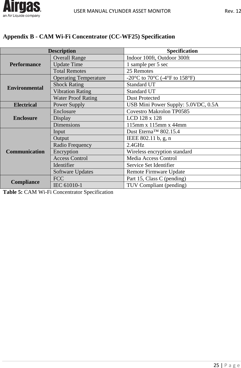
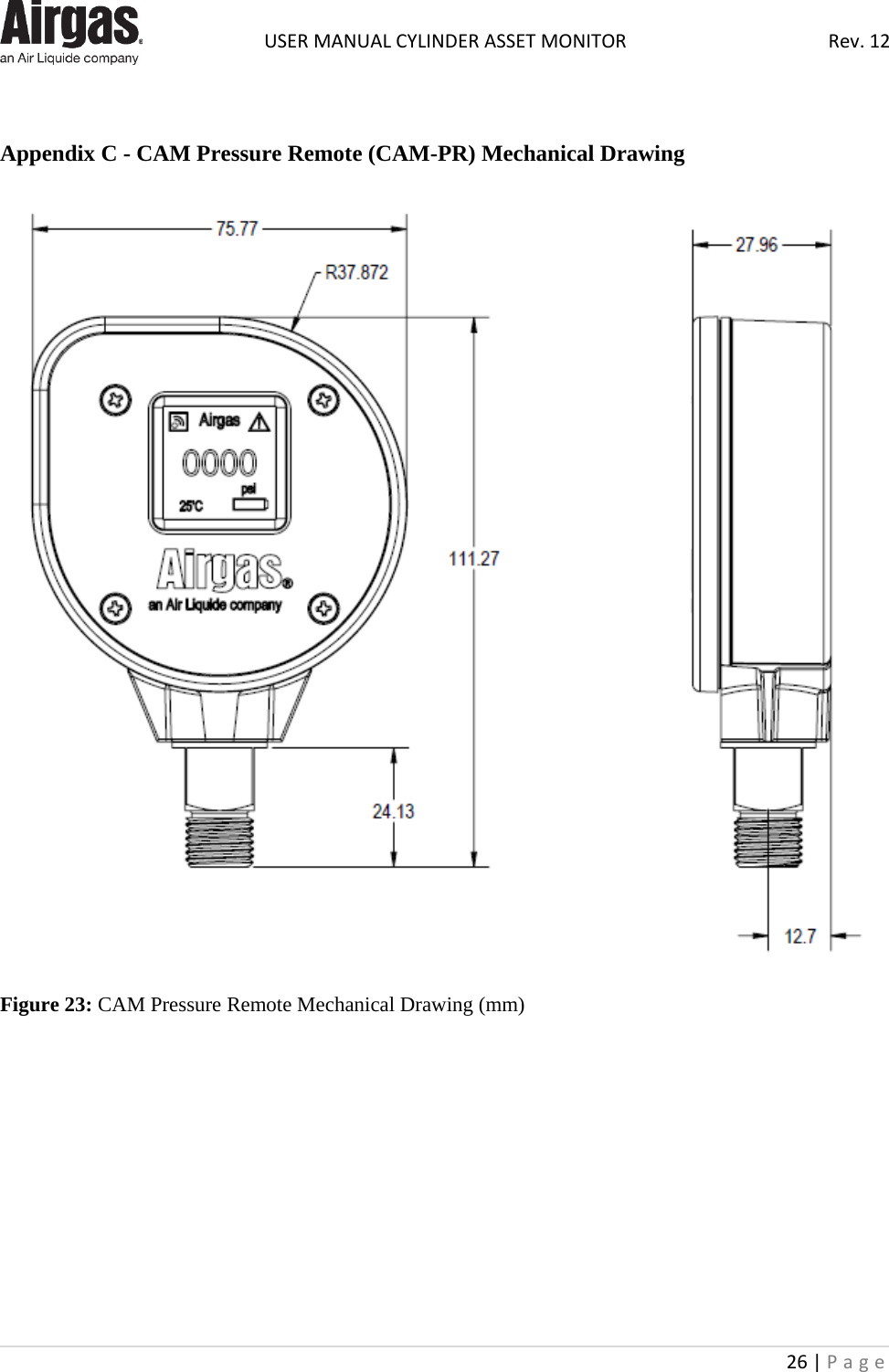
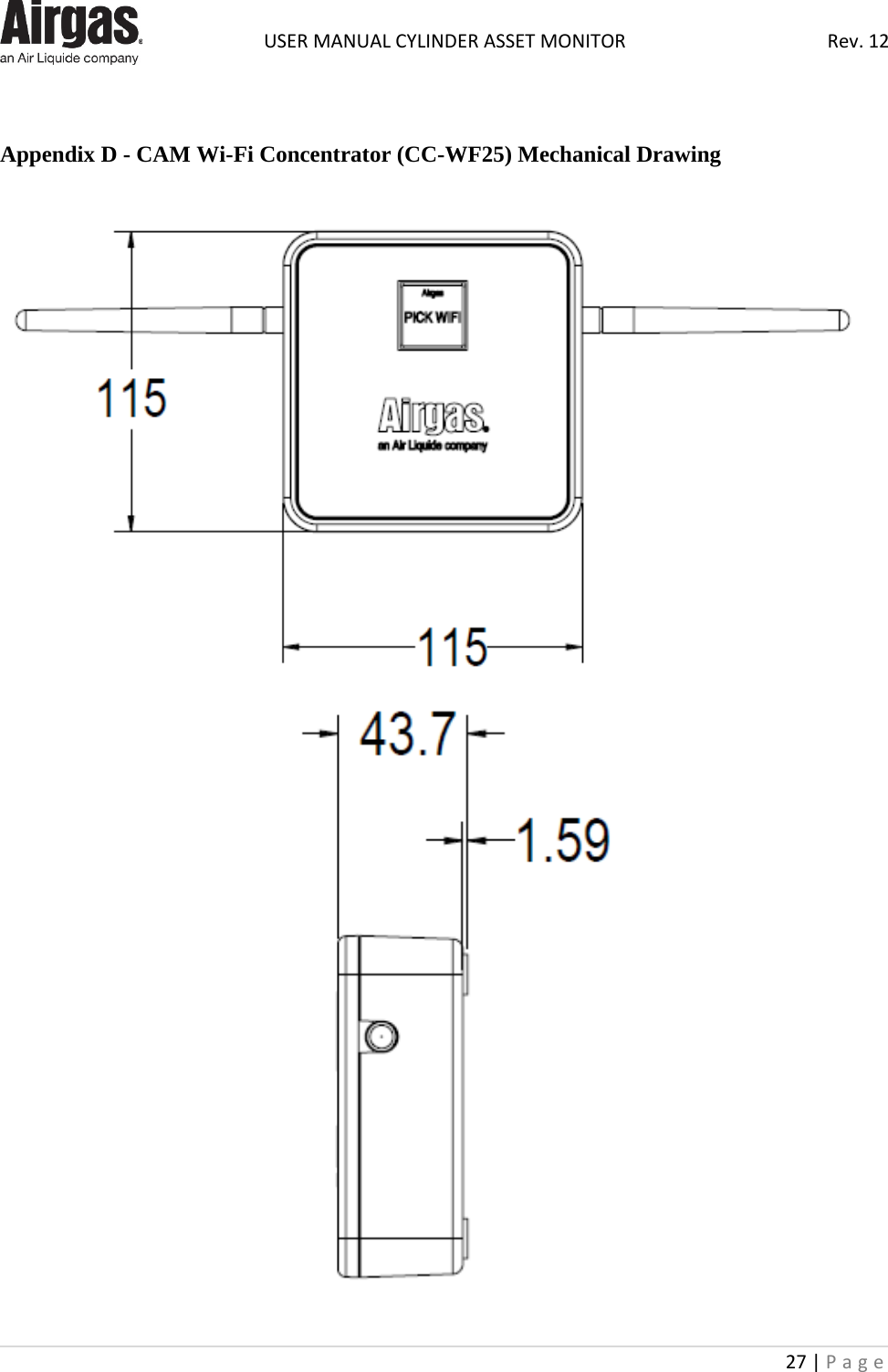
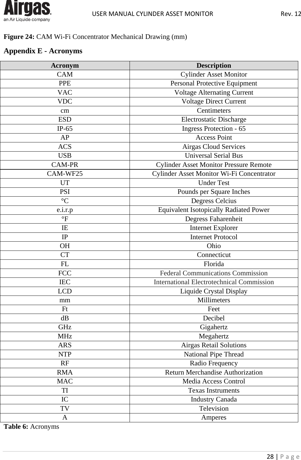
Airgas USA, LLC Cylinder Asset Monitor (CAM)

User Manual

 USER MANUAL CYLINDER ASSET MONITOR Rev. 12 1 | Page                       Cylinder Asset Monitor (CAM)   User Manual (DRAFT) Rev 12.0  May, 2017         DISCLAIMER  Information contained in this document is offered for use by technically qualified personnel at their discretion and risk.  All statements, technical information, and recommendations contained herein are based on tests and data, which we believe to be reliable; but the accuracy or completeness thereof is not guaranteed and no warranty of any kind is made with respect thereto. This information is not intended as a license to operate under or a recommendation to practice or infringe any patent of Airgas Inc., or others covering any process, composition of matter or use of the project described herein. Airgas Inc. assumes no liability for loss or damage incurred from the proper or improper use of such product.
 USER MANUAL CYLINDER ASSET MONITOR Rev. 12 2 | Page    1.0 Contents Page  1.0 Contents Page Page: 2 2.0 Introduction Page: 3 2.1 General Warnings Page: 3 2.2 Product Users Page: 3 2.3 Personal Protective Equipment Page: 3 2.4 Equipment Modifications Page: 3 2.5 Cylinder / Vessel Handling Page: 4 2.6 Safety Precautions Page: 4 2.7 Electrical Hazards Page: 4 3.0 Operating Summary Page: 6 4.0 General Specifications Page: 7 4.1 Power & Utilities Page: 7 4.2 General Operating Capacities Page: 7 5.0 Getting Started Page: 8 5.1 Inside the Box Page: 8 5.1.1 Maintenance Kit Page: 8 5.2 CAM Wi-Fi Concentrator Installation Page: 9 5.3 Connecting CAM Wi-Fi Concentrator to Wi-Fi Page: 10 5.3.1 Software Capabilities Page: 10 5.3.2 Data Communication & Firewall Configuration Page: 10 5.3.3 CAM Wi-Fi Concentrator Connection Page: 10 5.4 CAM Pressure Remote Installation Page: 12 6.0 CAM Pressure Remote Installation and Mounting Page: 14 6.1 Operating Temperature Page: 14 6.2 CAM Pressure Remote Installation with a Helium Regulator Page: 14 6.3 CAM Pressure Remote Installation with an Industrial Regulator Page: 14 7.0 Operating Procedure Page: 15 7.1 Latex Balloon Inflation Page: 15 7.2 Mylar Balloon Inflation Page: 15 7.3 Cylinder Re-Order Page: 15 8.0 General maintenance Page: 16 8.1 Operator Responsibilities Page: 16 8.2 Component Maintenance Page: 16 9.0 Troubleshooting Guide – System Page: 16 10.0 Regulatory Statements and Labels Page: 17 10.1 Product labels Page: 19 10.2 Regulatory Statement Page: 20 10.2.1 FCC Statement Page: 20 10.2.2 Innovations, Science and Economics Development Canada Statement Page: 21 10.2.3 TUV Statement Page: 22 11.0 Airgas Contacts Page: 23 Appendix A Pressure Mote (CAM-PR) Specification Page: 24 Appendix B Wi-Fi Concentrator (CC-WF25) Specification Page: 25 Appendix C Pressure Remote (CAM-PR) Mechanical Drawing Page: 26 Appendix D Wi-Fi Concentrator (CC-WF25) Mechanical Drawing Page: 27 Appendix E Acronyms Page: 28
 USER MANUAL CYLINDER ASSET MONITOR Rev. 12 3 | Page    2.0 Introduction   Please read User Manual completely before installing and operating a Cylinder Asset Monitor (CAM) instrument. Make sure that you read and understand all the related data. This includes all local safety procedures  and this publication. Changes or modifications not expressly approved by the party responsible for compliance could void the user’s authority to operate the equipment (47 CFR 15.21).  A complete digital copy of the Installation User Manual is available for download at http://testairgasbam.com/RDTelemetry/Portal/Downloads/Downloads.jsp.  2.1  General Warnings  The warnings in this manual supplement the safety policies of the user’s company. All users should be thoroughly trained in the safety policies of their company, the potential issues with equipment and materials within in the area where the equipment is located, relevant safety equipment within the area and the safe use of the equipment referenced in this manual. This manual should be kept with the system or equipment and be available for use.  2.2  Product Users  This system may contain hazardous liquids or gases under pressure. There may also be electrical voltages up to 110-230 VAC. The system or equipment is not to be used by untrained operators. Users must be trained in the following, as a minimum: • Operation of the system or equipment; • Handling of hazardous gases and liquids; • Handling of gases and liquids under pressure; • Emergency shutdown procedures, switches, valves or other devices to safely isolate the system; • Electrical safety precautions; and • Relevant safety equipment including: o Personal Protective Equipment (PPE); o Cylinder hand carts & cylinder restraints; o Fire alarm & extinguishing systems; and / or  o Other relevant alarm systems.  2.3   Personal Protective Equipment (PPE)  All personal protective equipment should be of safe design and construction, and should be maintained in a clean and reliable fashion. It should fit well and be comfortable to wear. If the personal protective equipment does not fit properly, it can make the difference between being safely covered or dangerously exposed.  2.4   Equipment Modifications  This system has been designed and tested for safe and efficient operation. Changes not approved by Airgas will void the warranty and may result in unpredictable results. Contact Airgas prior to making any changes or modifications to the equipment. Use only the liquids or gases specified for use with this system or equipment.
 USER MANUAL CYLINDER ASSET MONITOR Rev. 12 4 | Page    2.5   Cylinder/Vessel Handling  Cylinders or other vessels may contain hazardous liquids or gases under high pressure. Improper handling could release hazardous material to the environment and cause dangerous projectiles. Only properly trained personnel should handle cylinders and other vessels.  Whenever a cylinder is being moved, cylinder caps should be installed to protect the valve stem. If the valve stem is broken or damaged serious personal injury or death may result. All cylinders, full or empty, should be moved only when secured to a hand cart. Once placed in position a cylinder should be chained to a secure object or wall to prevent accidental knock over or other cylinder damage. All facility, local and state codes and standards that apply to cylinder handling, storage or use should also be followed when working with cylinders or other vessels.   CAUTION: Ensure that the cylinder(s) are securely attached to a wall bracket or cylinder stand. Always keep the cylinder cap on when moving cylinders. Take extra care to ensure the cylinder does not tip over. Do not remove cylinder cap until the cylinder is completely secure.  2.6  Safety Precautions  It is important to read and follow all notes, cautions and warnings before setting up, installing and operating a CAM instrument: • Some gas mixtures are dangerous (This includes mixtures that occur because of contamination); • It is dangerous to ignore the specified limits for the CAM system or to use the CAM system when it is not in its normal condition; • To prevent a dangerous release of pressure, isolate and bleed the system before you disconnect a pressure connection; • Do not use the CAM system in locations where explosive gas, vapor or dust are present; • This device has not been designed, tested or approved for use in any medical or nuclear application; • Never operate CAM devices outside of the recommended use outlined in the manual; • No co-location with other radio transmitters is allowed (By definition, co-location is when another radio device or its antenna is located within 20 cm of your unit and can transmit simultaneously with your unit); • Never install and/or continuously operate your wireless unit closer than 20 cm to nearby persons; and • Never remove the CAM device from the installed regulator (This device has been designed to operate in a permanent installation only).   CAUTION: Helium is a nontoxic, odorless, colorless, nonflammable gas stored in cylinders at high pressure. It can cause rapid suffocation when inhaled.   2.7  Electrical Hazards  It is common for the equipment provided to use 110-230 VAC. Guidelines on when work on energized systems may be authorized varies. The Customer must always minimize the risk to users who operate or maintain energized equipment. All users should read and understand all, facility, local and state relevant guidelines and mandates.
 USER MANUAL CYLINDER ASSET MONITOR Rev. 12 5 | Page        CAUTION: Care should be taken when handling electrical devices to minimize ESD exposure: • Avoid carpets in cool, dry areas as well as other electrostatic generating materials such as plastic, paper, or cardboard; • Leave digital gauges in their anti-static packaging until ready to be installed; • Dissipate static electricity before handling the digital gauge by touching a well-grounded metal object, such as the system unit unpainted metal chassis (If possible, use antistatic devices, such as wrist straps and floor mats); • When installing lithium ion batteries, avoid touching the contacts and components; and • Take care when connecting or disconnecting cables (A damaged cable can cause a short in the electrical circuit. When disconnecting a cable, always pull on the cable connector, case, or strain-relief loop, not on the cable itself).  Lithium batteries may get hot, explode or ignite and cause serious injury if exposed to abusive conditions. Be sure to follow the safety warnings listed below. Please do not: • Use a different battery other than what is specified in this manual; • Discharge the battery using any device except your CAM Pressure Remote; • Place the battery in fire or heat the battery; • Store batteries with other hazardous or combustible materials; • Install the battery backwards; • Connect the positive terminal and negative terminal of the battery to each other with any metal object (such as wire); • Carry or store the battery together with metal objects; • Pierce the battery with nails, strike the battery with a hammer, step on the battery or otherwise subject it to strong impacts or shocks; • Solder directly onto the battery; • Expose battery to water or salt water, or allow the battery to get wet; • Disassemble or modify the battery; and • Place the battery in microwave ovens or high-pressure containers.   CAUTION: When disposing of lithium batteries, ensure proper disposal in accordance with Local and State Laws and Regulations.  CAUTION: Immediately discontinue use of the battery if the battery emits an unusual smell, feels hot, changes color or shape, leaks or appears abnormal in any other way
 USER MANUAL CYLINDER ASSET MONITOR Rev. 12 6 | Page       3.0 Operating Summary  Thank you for selecting the Airgas Cylinder Asset Monitor (CAM) system. The CAM system will help you streamline the process of measuring, reporting metrics, local temperature and manage no-runout delivery of your high-pressure cylinders.   This product is intended to be used at the customer’s balloon inflation site. This device helps to provide a total cylinder management tool to the end user by providing 24/7 remote monitoring. Customer settings, usage, alarms and forecasting trends are to be implemented in the existing Airgas Web Dashboard through a Wi-Fi network.  The Pressure Remote is typically connected to a regulator of a compressed gas cylinder and acquires cylinder pressure, voltage, and temperature data. It then sends this data to the CAM Wi-Fi Concentrator. The CAM Pressure Remote is available in 1 model listed below: • CAM-PR, CAM Pressure Remote  The CAM Pressure Remote will be available in 3 part numbers as listed below: • PR-1.8NPT, pressure transducer size (1/8” National Pipe Thread (NPT)); • PR-1.4NPT, pressure transducer size (1/4” NPT); and • PR-1.4VCR, pressure transducer size (1/4” NPT).  The CAM Wi-Fi Concentrator collects and forwards the data acquired to the Airgas Cloud Services (ACS) Database. This device connects to the end users Wi-Fi Access Point (AP) and “Remote” while displaying the current connectivity and time. The CAM Wi-Fi Concentrator is available in 1 model: • CC-WF25, CAM Wi-Fi Concentrator.   Figure 1: CAM System Overview  In order to achieve the maximum communication range, the CAM Pressure  Remote and  CAM  Wi-Fi Concentrator must be free of all obstacles in line-of-sight. Note: it is important to understand that the environment might change over time due to new equipment and / or obstacles. If communication becomes limited move the CAM Wi-Fi Concentrator in order to find an ideal location.
 USER MANUAL CYLINDER ASSET MONITOR Rev. 12 7 | Page     4.0  General Specifications    This section provides the general specifications of the CAM as provided by Airgas Research & Development, Cheshire, Connecticut.  4.1   Power & Supply Utilities  Many factors such as ambient temperature conditions and the transmitting rate can have a big effect on the life of the lithium ion battery. Transmitting data places a large demand of the battery in your CAM Pressure Remote. Conditions that affect battery life are outlined below: • The transmit rate of the CAM  Pressure  Remote  (slower the transmit rate set, the longer the battery device life); and • Constant connectivity of the CAM  Pressure  Remote to the CAM  Wi-Fi  Concentrator (more consistent connectivity, the longer the battery device life).  4.2   General Operating Capacities  Description Parameter Inert Gases YES Corrosive Gases YES Flammable NO Accuracy 3% @ 25°C (77°F) Overall Range Indoor 100ft, Outdoor 300ft CAM Pressure Remote Pressure Range 0 to 3000 PSI Total Wireless Remotes 25 Operating Temperature -20°C to 70°C (-4°F to 158°F) Table 1: General Operating Capacities
 USER MANUAL CYLINDER ASSET MONITOR Rev. 12 8 | Page     5.0  Getting Started  This section outlines how to setup and configure a CAM Pressure Remote and CAM Wi-Fi Concentrator before installation and use.    CAUTION: The CAM Wi-Fi Concentrator utilizes a Universal Serial Bus (USB) Wall Adapter to power the device. Be sure to follow the safety warnings listed below:  • Do not use a different/non-approved USB Wall Adapter or Micro USB Cable other than what is provided; and • Avoid tampering with USB  Wall Adapter, Micro USB Cable or CAM  Wi-Fi Concentrator Micro USB connection.  Once the package is received, remove the packing list and verify that you have received all equipment. If you have any questions about the shipment, please call Airgas Retail Services at 1-800-329-0010.  5.1  Inside the Box       Figure 2: 1 x CAM Wi-Fi Concentrator Figure 3: 1 x USB Wall Adapter Figure 4: 1 x Micro USB Cable    Figure 5: 1 x CAM Pressure Remote Figure 6: 1 x Maintenance Kit Figure 7: 1 x Helium Regulator  5.1.1  Maintenance Kit     Figure 8: 1 x Phillips Head Screw Driver Figure 9: 2 x Lithium Batteries Figure 10: 2 x O-Ring Seals
 USER MANUAL CYLINDER ASSET MONITOR Rev. 12 9 | Page     5.2  CAM Wi-Fi Concentrator Installation  The first step to installing your CAM system is to supply power to the CAM Wi-Fi Concentrator. This involves the following steps: • Connect the Micro USB Cable (USB end) to the USB Wall Adapter; • Then connect USB Wall Adapter to the power outlet; and   Figure 11: USB Cable to USB Wall Adapter  • Then connect the Micro USB Cable (Micro USB end) to the CAM Wi-Fi Concentrator (Note: Image below depicts preceding enclosure design).   Figure 12: USB Cable to CAM Wi-Fi Concentrator  At power up, the Airgas logo will appear on the CAM Wi-Fi Concentrator screen for 15 seconds. The screen below demonstrates the Liquid Crystal Display (LCD) screen of CAM Wi-Fi Concentrator:   Figure 13: CAM Wi-Fi Concentrator LCD Startup  This screen will be visible until the unit connects to a Wi-Fi Access Point (AP). The screen will only be displayed for a few seconds if the unit has already been assigned to an AP and automatically connects to it. If an AP has not been assigned, then this screen will display “Pick Wi-Fi” until the Wi-Fi connection has been completed. The LCD displays:  • In the middle of the screen, Wi-Fi network SSID will be displayed based upon which AP is connected to; •  Signal bars will indicate the signal strength of CAM Wi-Fi Concentrator associated with Wi-Fi router. The closer the device is to the Wi-Fi router, the higher the signal strength; •  Shows time of day in hours and minutes. Shortly after the unit connects to the network, the time will be updated. The time will be updated to an offset from Greenwich Mean Time (GMT);
 USER MANUAL CYLINDER ASSET MONITOR Rev. 12 10 | Page    •  Will indicate the data flow between the device and Airgas infrastructure; and •  Will be displayed as soon the device is  connected to the Wi-Fi network selected by the customer. 5.3  Connecting CAM Wi-Fi Concentrator to Wi-Fi   5.3.1  Software Compatibility  When provisioning the CAM Wi-Fi Concentrator either the users: mobile phone, tablet or computer must meet the minimum device compatibility requirements with either: • Firefox; • Safari; • Chrome; and / or  • Internet Explorer (IE) browsers.  5.3.2  Data Communication & Firewall Configuration The CAM Wi-Fi Concentrator uses HTTP to communicate with the Airgas Cloud Services. Data is sent via ports 80 & 443. In/out data communication rules will need to be added to any existing firewalls as applicable to your network set-up to permit the data to be sent to the Airgas Cloud Services. In summary, the following ports will need to be open for all communications on the networks: • Port 80; and • Port 443.  The CAM Wi-Fi Concentrator sends its information to the following domain:  http://testairgasbam.com/RDTelemetry/  Please note, the IP address of the Airgas Cloud Services is subject to change.  5.3.3  CAM Wi-Fi Concentrator Connection  By completing this process it will make the CAM Wi-Fi Concentrator visible to the CAM system. Begin by identifying your AP for the CAM Wi-Fi Concentrator, using a computer, smart phone or tablet. Look for a wireless network name that starts with “Airgas-CAM-XXXXXX“.  Figure 14: CAM Wi-Fi Concentrator AP CAM Wi-Fi Concentrator Access Point
 USER MANUAL CYLINDER ASSET MONITOR Rev. 12 11 | Page     Once you have selected the AP, open a web browser and enter the following address:  http://airgas.cam.net/profiles_config.html  You will be redirected to Wi-Fi connectivity profile setting web page. There will be list of available networks on the page.  Figure 15: CAM Wi-Fi Concentrator Provisioning Step 1  • Select AP for CAM Wi-Fi Concentrator to connect to from the “Select a Wi-Fi” Drop down menu • And / Or: Type into Add Wi-Fi Box and Select Add Wi-Fi; • Click Continue.  Figure 16: CAM Wi-Fi Concentrator connection Step 2  • Select a Security Type; • Type in a Security Key; and • Click Connect.  Figure 17: CAM Wi-Fi Concentrator connection Step 3  • You will be notified when the CAM Wi-Fi Concentrator connects to the Wi-Fi network;
 USER MANUAL CYLINDER ASSET MONITOR Rev. 12 12 | Page    • Once the profile has been added, the CAM Wi-Fi Concentrator will no longer act as an AP, and you will be disconnected.    5.4  CAM Pressure Remote Installation  The third step to installing your CAM system is to supply power to the CAM Pressure Remote.    CAUTION: Do not attempt to replace the batteries while the unit is pressurized. This will cause the CAM Pressure Remote to improperly report and could cause a safety issue.   This section will involve the operator/user of the device to gain access to the internal compartment of the CAM Pressure Remote. A screw driver will be supplied in the maintenance kit. This screw driver must be used to gain access to the internal compartment of the CAM Pressure Remote.   CAUTION: Do not attempt to misuse device once internal compartment is exposed. This will cause the CAM Pressure Remote to improperly report and could cause a safety issue.   This involves the following steps: • Remove the 4 screws on the front cover of the CAM Pressure Remote using a Philips head screw driver; • Open CAM Pressure Remote;  • Insert two Lithium Ion batteries into the battery compartment;   CAUTION: Note the polarity of the batteries (+ +).  • Replace front cover of CAM Pressure Remote; and • Insert the 4 screws on the front cover of the CAM Pressure Remote Using a Philips Head Screw Driver.  Figure 18: CAM Pressure Remote battery install.   CAUTION: The same four screws removed in this procedure must be re-installed into the CAM Pressure  Remote housing or you will not have the proper IP-65 seal. Failure to install these screws correctly may result in damage to the device when exposed to wet or hazardous condition.  You should see the gauge LCD show the Airgas logo and then show the initial data shown here:
 USER MANUAL CYLINDER ASSET MONITOR Rev. 12 13 | Page      Figure 19: CAM Pressure Remote LCD •   Network icon blinks while in network negotiation and it will be solid on after it successfully connects to the CAM Wi-Fi Concentrator; •  This icon is only displayed if the cylinder pressure is lower than preset alarm setting. This icon will appear, and fill request will be scheduled; •  Displays the pressure measurement; • Indicating battery level. To avoid any interruption in monitoring services, monthly inspection is suggested; and •  This icon indicates the environment temperature in degrees Celsius.   CAUTION: Be sure to follow the safety warnings listed below:  • Do not mix ages or brands of batteries; • Do not use store bought AA batteries;  • Do not replace batteries in hazardous areas; and • To provide maximum battery life, replace both batteries.
 USER MANUAL CYLINDER ASSET MONITOR Rev. 12 14 | Page     6.0  CAM Pressure Remote Installation and Mounting  Please apply precautionary safety procedures during installation. The CAM Pressure Remote has been specifically designed to meet IP-65 standard (protected from low pressure water jets from any direction, limited ingress protection (IP)). The CAM Pressure Remote can be installed in locations where it will be intermittently exposed to spraying water, rain or high humidity.    CAUTION: The CAM Pressure Remote should never be submerged or used under water.  6.1  Operating Temperature  The CAM Pressure Remote should only be installed and operated in locations that maintain an ambient temperature between -20°C to 70°C (-4°F to 158°F).  6.2  CAM Pressure Remote Installation with a Helium Regulator  Please apply precautionary safety procedures during installation. This involves the following steps: • Attach helium regulator to cylinder (Note: Do not carry the regulator by the CAM  Pressure Remote, this could cause undue stress to the unit); • Only use the hand tight wheel on helium regulator to tighten to the cylinder; and • Once the hand tight wheel is tight apply pressure from the cylinder.  For future use, make note of the 16 digit identification code on the label of the CAM Pressure Remote.   Note: Visually check O ring on stem of regulator for wear with each cylinder change to prevent helium loss (The O ring is usually the only failed part of regulator - replace as necessary).   6.3  CAM Pressure Remote Installation with an Industrial Regulator  The  CAM  Pressure  Remote comes standard with either a 1/4 or 1/8 NPT connection. Good piping practices are required. Always use Teflon tape or pipe sealant on the gauge threads. It is recommended to use a wrench on the wrench flat of the gauge to tighten the gauge to the process.   CAUTION: Never tighten gauge threads by holding the body of the CAM Pressure Remote. Doing so will damage the gauge and make the gauge inoperable.
 USER MANUAL CYLINDER ASSET MONITOR Rev. 12 15 | Page     7.0  Operating Procedures  7.1  Latex Balloon Inflation  To fill latex balloons, insert the opening of the balloon onto the latex nozzle. The latex nozzle on the regulator is designed to release helium when tilted at an angle. Inflate the balloon to the desired size. Be careful not to over inflate the balloon as Helium expands rapidly.    CAUTION: Do not place balloons near heat or A/C vents.      Figure 20: (Left) Latex Balloon Inflation, (Right) Foil Balloon Inflation  7.2  Foil Balloon Inflation  To fill foil balloons, slide the balloon opening over the push valve. The push valve on the regulator is designed to release helium when pushed in. To inflate, hold the balloon while engaging the push valve.    CAUTION: Do not push the valve too far into the balloon, as this will cause the self-seal valve to tear. The regulator is designed to stop the flow of Helium when the balloon is fully inflated.  7.3  Cylinder Re-Order  Airgas recommends that when the cylinder pressure is reduced to 500 psi, it is time to re-order your Helium. Mark the cylinder once it is empty for easy reference at time of pickup, then contact Airgas Retail Solutions.  Sales/Services: Airgas Retail Solutions: 1-800-329-0010
 USER MANUAL CYLINDER ASSET MONITOR Rev. 12 16 | Page      8.0  General Maintenance  Preventative maintenance, when properly performed, will help to ensure that the system will continue to operate properly. The system should be inspected periodically so that defects can be corrected before they result in failure.  The scheduling of preventative maintenance checks and services should be based on the operating environment and the frequency of operation of the system. All safety procedures and warnings should be observed to prevent injury to yourself and others while servicing or maintaining the system.  8.1  Operator Responsibilities  • Keep the system and the area around the system clean; • Monitor system pressures and note any significant deviations from typical operating parameters; and • Replace any suspect pressure components.  8.2  Component Maintenance  The CAM Pressure Remote has been built, tested and factory calibrated to meet the specifications listed in the Appendix A and Appendix B. If your  CAM Pressure Remote or CAM Wi-Fi Concentrator requires service please contact Airgas Retail Solutions (ARS).  Sales/Services: Airgas Retail Solutions: 1-800-329-0010  See section 4.2 maintenance Kit for contents of Maintenance Kit.  It is recommended: • The CAM Pressure Remote be opened using the provided screw driver provided by following installation steps outlined in section 4.4 CAM Pressure Remote Installation; and • The O-ring seals are provided to ensure if regulator seals become compromised that they can be replaced promptly.
 USER MANUAL CYLINDER ASSET MONITOR Rev. 12 17 | Page      9.0  Troubleshooting Guide - System  All users must read and understand this manual before attempting any operation or service of this equipment.  Personnel troubleshooting the system must be trained in the procedures for safe handling of hazardous gases and liquids under pressure. All users must be instructed in the proper use of all required personal protective equipment (PPE).  Description Identification Resolution *CAM Pressure Remote: CAM-PR, **CAM Wi-Fi Concentrator: CC-WF25 Batteries in *CAM-PR fall below working voltage causing the device to no longer function correctly Device stops working and Potential Battery Low Alarm Notification Batteries will need to be replaced in the *CAM-PR Batteries polarity is incorrectly inserted into *CAM-PR Device will not work and will remain in missed readings  Batteries will need to have polarities rearranged Customer uses non-approved batteries in the *CAM-PR Device may not function correctly or work at all, potential Battery Low Alarm Notification Batteries will need to be replaced with approved batteries Batteries exhibit corrosion in the *CAM-PR Device may not function correctly or stop working, potential Battery Low Alarm Notification Batteries will need to be replaced in the device, potential RMA if connectors need cleaning LCD is Damaged Device may not function correctly or stop working and may go into missed readings if damaged Potential RMA if device is damaged Device is dropped and damaged internally or externally Device may not function correctly or stop working and may go into missed readings if damaged Potential RMA if device is damaged Front Cover of *CAM-PR is not properly installed IP65 not maintained, *CAM-PR may go into missed readings if damaged Check cover for proper fitment before screwing into the device Screw Treads in *CAM-PR become cross treaded when screwing in Screw does not screw in or remain tight in the mold Manual recommends not to over tighten screws Battery Wires are pulled out when *CAM-PR is opened Wires pulled out and no longer connected and may not function correctly or work at all Potential RMA if device is damaged Battery Wire Connector pulled out when *CAM-PR is opened Battery Wire Connector pulled out and no longer connected, device may not function correctly or work at all Potential RMA or by connecting the connector back to the PCB Transducer Wires are pulled out when *CAM-PR is opened Transducer Wires pulled out and no longer connected, device may not function correctly or work at all Potential RMA if device is damaged. Transducer Wire Connector pulled out when *CAM-PR is opened Transducer Wire connector pulled out and no longer connected, device may not function correctly or work at all Potential RMA or by connecting the connector back to the PCB.  *CAM-PR loses connection to **CC-WF25 Device goes into missed readings and icon in top left hand corner of the *CAM-PR LCD will start to blink Move device closer and check surrounding area for Radio Frequency (RF) obstructions Device is exposed to a temperatures exceeding limits specified in Manual Device may not function correctly or stop working, device may go into Missed Readings if damaged Potential RMA if damaged. Device may recover if returned to ambient temperature Foreign substance leaked into device Device may not function correctly or stop working, device may go into Missed Readings if damaged Potential RMA if device is damaged
 USER MANUAL CYLINDER ASSET MONITOR Rev. 12 18 | Page    **CC-WF25 loses connection to Wi-Fi *CAM-PR goes into Missed Readings on the ACS, system no longer reports Check for Wi-Fi Visibility, and time on **CC-WF25. Reset and re provision if necessary **CC-WF25 loses power *CAM-PR goes into missed readings on the ACS, **CC-WF25 can no longer report Reconnect Cable and **CC-WF25 will reconnect to Wi-Fi and continue reporting **CC-WF25 loses power *CAM-PR goes into missed readings on the ACS, **CC-WF25 can no longer report Reconnect Cable and **CC-WF25 will reconnect to Wi-Fi and continue reporting  **CC-WF25 no longer functions correctly due to disconnected antenna *CAM-PR goes into missed readings on the ACS, **CC-WF25 can no longer report Reconnect antenna, Potential RMA if **CC-WF25 is damaged **CC-WF25 no longer functions correctly due to damaged antenna *CAM-PR goes into missed readings on the ACS, **CC-WF25 can no longer report Replace antenna, Potential RMA if **CC-WF25 is damaged **CC-WF25 no longer functions correctly due to damaged cable *CAM-PR goes into missed readings on the ACS, **CC-WF25 can no longer report Replace cable, Potential RMA if **CC-WF25 is damaged **CC-WF25 no longer functions correctly due to damaged USB adapter *CAM-PR goes into missed readings on the ACS, **CC-WF25 can no longer report Replace USB adapter, Potential RMA if **CC-WF25 is damaged **CC-WF25 can no longer report if exposed to excess voltage. *CAM-PR goes into missed readings Alarm on the ACS USB adapter meets IEC 61000-4-5 standard which is a voltage surge up to 4000V Access to Ports 443 and 80/123 blocked **CC-WF25 cannot connect to Wi-Fi, *CAM-PR goes into missed readings on the ACS Contact IT Department to unblock ports to **CC-WF25 **CC-WF25 is moved or is out of range from the Wi-Fi signal *CAM-PR goes into missed readings on the ACS, **CC-WF25 can no longer report Move **CC-WF25 to Router **CC-WF25 no longer reports, *CAM-PR goes into missed readings  *CAM-PR goes into missed readings on the ACS, **CC-WF25 can no longer report Consult IT Department **CC-WF25 no longer reports, *CAM-PR goes into missed readings  *CAM-PR goes into missed readings on the ACS, **CC-WF25 can no longer report Consult IT Department *CAM-PR no longer reports to **CC-WF25, *CAM-PR goes into missed readings  *CAM-PR goes into missed readings on the ACS, **CC-WF25 can no longer connect to *CAM-PR Check Net ID of *CAM-PR and **CC-WF25, Change if needed Leaking gas out of Regulator Loss of Product when not in use, this can be seen on the ACS Pressure Graph or potentially heard Use ACS to confirm, tighten or re-tape regulator, potential RMA of Regulator Leaking gas out of Regulator Loss of Product when not in use, this can be seen on the ACS Pressure Graph or potentially heard Use ACS to confirm, Replace O-ring seal on regulator, potential RMA of Regulator Leaking gas out of Regulator Loss of Product when not in use, this can be seen on the ACS Pressure Graph or potentially heard Use ASC to confirm, Replace Components or consult ARS. Potential RMA of Regulator System is exposed to different size cylinders at one location Customer or SAP will need to notify System Customer or SAP will need to notify ARS to manually adjust inventory Each device has a Unique MAC ID unique to that device Loss of Devices in the field Track devices when shipped and provisioned Incorrect provisioning information given to ARS Device unable to be configured Outline clearly the required information from the customer Incorrect Wi-Fi Credentials Device unable to be provisioned Outline clearly the required information from the customer Table 2: Troubleshooting Guidelines
 USER MANUAL CYLINDER ASSET MONITOR Rev. 12 19 | Page      10.0   Regulatory Statements and Labels  10.1  Product Labels         Label 1: CAM Wi-Fi Concentrator TI Module (CAM-CC3200M) Product Label. To Scale        Label 1 Exploded View: CAM Wi-Fi Concentrator TI Module (CAM-CC3200M) Product Label. Not to Scale            Label 2: CAM Pressure Remote (CAM-PR) Product Label. To Scale           Label 2 Exploded View: CAM Pressure Remote (CAM-PR) Product Label. Not to Scale           Label 3: CAM Wi-Fi Concentrator (CC-WF25) Product Label. To Scale               Label 3 Exploded View: CAM Wi-Fi Concentrator (CC-WF25) Product Label. Not to Scale    Model #: CAM-CC3200M   FCC ID: 2ALBX-CAMWFCTIR01     IC: 22533-CAMWFCTIR01    Model #: CAM-CC3200M   FCC ID: 2ALBX-CAMWFCTIR01     IC: 22533-CAMWFCTIR01   Product Name: Wi-Fi Concentrator Model #: CC-WF25 FCC ID: 2ALBX-CAMWFCTIR01   IC: 22533-CAMWFCTIR01 Contains: FCC ID: 2ALBX-CAMWFCTIR01   Contains: IC: 22533-CAMWFCTIR01 This device complies with Part 15 of the FCC rules. Operation is subject to the following two conditions: 1.) This device may not cause harmful interference. 2.) This device must accept any interference received, including interference that may cause undesired operations.  Power Supply:   5.0VDC, 0.5A Product Name: Wi-Fi Concentrator Model #: CC-WF25 FCC ID: 2ALBX-CAMWFCTIR01   IC: 22533-CAMWFCTIR01 Contains: FCC ID: 2ALBX-CAMWFCTIR01   Contains: IC: 22533-CAMWFCTIR01 This device complies with Part 15 of the FCC rules. Operation is subject to the following two conditions: 1.) This device may not cause harmful interference. 2.) This device must accept any interference received, including interference that may cause undesired operations.  Power Supply:   5.0VDC, 0.5A Product Name: CAM Pressure Remote Model #: CAM-PR   FCC ID: 2ALBX-CAMPRMR01   IC: 22533-CAMPRMR01  This device complies with Part 15 of the FCC rules. Operation is subject to the following two conditions: 1.) This device may not cause harmful interference. 2.) This device must accept any interference received, including interference that may cause undesired operations. Product Name: CAM Pressure Remote Model #: CAM-PR   FCC ID: 2ALBX-CAMPRMR01   IC: 22533-CAMPRMR01  This device complies with Part 15 of the FCC rules. Operation is subject to the following two conditions: 1.) This device may not cause harmful interference. 2.) This device must accept any interference received, including interference that may cause undesired operations.
 USER MANUAL CYLINDER ASSET MONITOR Rev. 12 20 | Page      10.2  Regulatory Statement  10.2.1  FCC Statement    Figure 20: FCC Mark for CAM Pressure Remote and CAM Wi-Fi Concentrator  DUST Manager Module FCC ID: 2ALBX-CAMWFCLR01 DUST Remote Module   FCC ID: 2ALBX-CAMPRMR01  TI Module    FCC ID: 2ALBX-CAMWFCTIR01  47 CFR 15.19 –This device complies with Part 15 of the FCC rules. Operation is subject to the following two conditions:  1) This device may not cause harmful interference. 2) This device must accept any interference received, including interference that may cause undesired operations.  47 CFR 15.105 – This equipment has been tested and found to comply with the limits for a Class B digital device, pursuant to part 15 of the FCC Rules. These limits are designed to provide reasonable protection against harmful interference in a residential installation. This equipment generates, uses and can radiate radio frequency energy and, if not installed and used in accordance with the instructions, may cause harmful interference to radio communications. However, there is no guarantee that interference will not occur in a particular installation. If this equipment does cause harmful interference to radio or television reception, which can be determined by turning the equipment off and on, the user is encouraged to try to correct the interference by one or more of the following measures:   • Reorient or relocate the receiving antenna. • Increase the separation between the equipment and receiver. • Connect the equipment into an outlet on a circuit different from that to which the receiver is connected. • Consult the dealer or an experienced radio/TV technician for help.  47 CFR 15.21  –  Changes or modifications not expressly approved by the party responsible for compliance could void the user’s authority to operate the CAM System.  47 CFR 15.18.213 – Information on the following matters shall be provided to the user in the instruction manual or on the packaging if an instruction manual is not provided for any type of ISM equipment: • The interference potential of the device or system. • Maintenance of the system. • Simple measures that can be taken by the user to correct interference. • The CAM System may cause interference to radio equipment and should not be installed near maritime safety communications equipment or other critical navigation or communication equipment operating between 0.45-30 MHz.
 USER MANUAL CYLINDER ASSET MONITOR Rev. 12 21 | Page      10.2.2  Innovations, Science and Economics Development Canada ISEDC Statement   DUST Manager Module IC ID: 22533-CAMWFCLR01 DUST Remote Module   IC ID: 22533-CAMPRMR01  TI Module   IC ID: 22533-CAMWFCTIR01  Under Industry Canada regulations, this radio transmitter may only operate using an antenna of a type and maximum (or lesser) gain approved for the transmitter by Industry Canada.   To reduce potential radio interference to other users, the antenna type and its gain should be so chosen that the equivalent isotopically radiated power (e.i.r.p.) is not more than that necessary for successful communication.  Conformément à la réglementation d'Industrie Canada, le présent émetteur radio peut fonctionner avec une antenne d'un type et d'un gain maximal (ou inférieur) approuvé pour l'émetteur par Industrie Canada.   Dans le but de réduire les risques de brouillage radioélectrique à l'intention des autres utilisateurs, il faut choisir le type d'antenne et son gain de sorte que la puissance isotrope rayonnée équivalente (p.i.r.e.) ne dépasse pas l'intensité nécessaire à l'établissement d'une communication satisfaisante.  RSS-GEN.  ISSUE 4, SECTION 8.3  –  This radio transmitter (22533-CAMWFCLR01, CC-WF25 & 22533-CAMWFCTIR01, CC-WF25) has been approved by Industry Canada to operate with the antenna types listed below with the maximum permissible gain and required antenna impedance for each antenna type indicated. Antenna types not included in this list, having a gain greater than the maximum gain indicated for that type, are strictly prohibited for use with this device.  Le présent émetteur radio (22533-CAMWFCLR01, CC-WF25 & 22533-CAMWFCTIR01, CC-WF25) a été approuvé par Industrie Canada pour fonctionner avec les types d'antenne énumérés ci-dessous et ayant un gain admissible maximal et l'impédance requise pour chaque type d'antenne. Les types d'antenne non inclus dans cette liste, ou dont le gain est supérieur au gain maximal indiqué, sont strictement interdits pour l'exploitation de l'émetteur.  Manufacture Description Quantity Part Number Tekfun 2dBi 2.4GHz Antenna, RP-SMA (M) L=109, White 2 M04-SR-W Table 3: Description of Detachable Antenna used in Wi-Fi Concentrator  RSS-GEN.  ISSUE 4, SECTION 8.4  –  This device complies with Industry Canada’s license-exempt RSSs. Operation is subject to the following two conditions:  1) This device may not cause interference; and  2) This device must accept any interference, including interference that may cause undesired operation of the device.
 USER MANUAL CYLINDER ASSET MONITOR Rev. 12 22 | Page     10.2.3  TUV Statement     Figure 21: CAM Pressure Remote and CAM Wi-Fi Concentrator TUV Mark  The Cylinder Asset Monitor CAM Pressure Remote and CAM Wi-Fi Concentrator has been tested to the IEC 61010-1 3rd edition standard by TUV Rheinland®.   IEC 61010-1 3rd EDITION, CLAUSE 5.2 – If OPERATOR wishes to gain internal access, using the  provided SCREWDRIVER, the equipment must first be isolated or disconnect from the HAZARDOUS LIVE voltage before access.   Figure 22: Warning Marking. Symbol 14 of Table 1, IEC 61010-1 3rd EDITION  IEC 61010-1 3rd EDITION, CLAUSE 5.4.4 – If the equipment is used in a manner not specified by the manufacturer, the protection provided by the equipment may be impaired.
 USER MANUAL CYLINDER ASSET MONITOR Rev. 12 23 | Page     11.0  Airgas Contacts  Airgas Specialty Gases Engineered Solutions Group 21610 Alexander Road. Oakwood Village, OH  44146 Phone: 440.232.7242 / 800.282.1524 Fax: 440.232.7799   Airgas Specialty Gases Airgas Research & Development 180 Sandbank Road. Cheshire, CT 06410 Phone: 203.272.5800   Airgas Specialty Gases Airgas Retail Solution 7401 114th Avenue. Largo, FL 33773 Phone: 727.341.8207 / 800.329.0010
 USER MANUAL CYLINDER ASSET MONITOR Rev. 12 24 | Page     Appendix  Appendix A - CAM Pressure Remote (CAM-PR) Specification  Description Specification Product Type Inert Gases YES Corrosive Gases YES  Flammable NO Performance Accuracy 3% @ 25°C (77°F) Overall Range Indoor 100ft, Outdoor 300ft Pressure Range 0 to 3000 PSI LCD Update Rate 5 seconds Reporting Rate 5 minutes Environmental  Operating Temperature -20°C to 70°C (-4°F to 158°F) Shock Rating Standard Under Test (UT) Vibration Rating Standard UT Water Proof Rating IP-65 Mechanical Mechanical Connection Only 1 (Transducer) Mechanical Fitting 1/4 MNPT Male, 1/8 MNPT Male, 1/4 VCR  Wetted Material 316L Stainless Steel Electrical Battery Supply  2 x AA 3.6VDC Lithium Batteries Battery Supply Life  5 Years @ 12 samples per hour Housing Material Covestro Makrolon TP0585 Display LCD 128 x 128 Dimensions 76mm x 76mm x 28mm  Communication Output Dust Eterna™ 802.15.4 Output Frequency 2.4GHz Encryption AE128 bit  Access Control Media Access Control  Identifier Service Set Identifier  Software Updates Remote Firmware Update Compliance FCC Part 15, Class C (pending) IEC 61010-1 TUV Compliant (pending) Table 4: CAM Pressure Remote Specification
 USER MANUAL CYLINDER ASSET MONITOR Rev. 12 25 | Page     Appendix B - CAM Wi-Fi Concentrator (CC-WF25) Specification  Description Specification Performance Overall Range Indoor 100ft, Outdoor 300ft Update Time 1 sample per 5 sec Total Remotes 25 Remotes Environmental  Operating Temperature -20°C to 70°C (-4°F to 158°F) Shock Rating Standard UT Vibration Rating Standard UT Water Proof Rating Dust Protected Electrical Power Supply  USB Mini Power Supply: 5.0VDC, 0.5A Enclosure Enclosure Covestro Makrolon TP0585 Display LCD 128 x 128 Dimensions 115mm x 115mm x 44mm Communication Input  Dust Eterna™ 802.15.4 Output  IEEE 802.11 b, g, n Radio Frequency 2.4GHz Encryption Wireless encryption standard  Access Control Media Access Control  Identifier Service Set Identifier  Software Updates Remote Firmware Update Compliance FCC Part 15, Class C (pending) IEC 61010-1 TUV Compliant (pending) Table 5: CAM Wi-Fi Concentrator Specification
 USER MANUAL CYLINDER ASSET MONITOR Rev. 12 26 | Page     Appendix C - CAM Pressure Remote (CAM-PR) Mechanical Drawing  Figure 23: CAM Pressure Remote Mechanical Drawing (mm)
 USER MANUAL CYLINDER ASSET MONITOR Rev. 12 27 | Page     Appendix D - CAM Wi-Fi Concentrator (CC-WF25) Mechanical Drawing
 USER MANUAL CYLINDER ASSET MONITOR Rev. 12 28 | Page    Figure 24: CAM Wi-Fi Concentrator Mechanical Drawing (mm) Appendix E - Acronyms Acronym Description CAM Cylinder Asset Monitor PPE Personal Protective Equipment VAC Voltage Alternating Current VDC Voltage Direct Current cm Centimeters ESD Electrostatic Discharge IP-65 Ingress Protection - 65 AP Access Point ACS Airgas Cloud Services USB Universal Serial Bus CAM-PR Cylinder Asset Monitor Pressure Remote CAM-WF25 Cylinder Asset Monitor Wi-Fi Concentrator UT Under Test PSI Pounds per Square Inches °C Degress Celcius e.i.r.p Equivalent Isotopically Radiated Power °F Degress Faharenheit IE Internet Explorer IP Internet Protocol OH Ohio CT Connecticut FL Florida FCC Federal Communications Commission IEC International Electrotechnical Commission LCD Liquide Crystal Display mm Millimeters Ft Feet dB Decibel GHz Gigahertz MHz Megahertz ARS Airgas Retail Solutions NTP National Pipe Thread RF Radio Frequency RMA Return Merchandise Authorization MAC Media Access Control TI Texas Instruments IC Industry Canada TV Television A Amperes Table 6: Acronyms

Navigation menu