Airgo Networks AGN1201AP0000 True MIMO Access Point User Manual 1 of 4
Airgo Networks Inc. True MIMO Access Point 1 of 4
Contents
User manual 1 of 4

Airgo Networks, Inc.
900 Arastradero Road
Palo Alto, CA 94304
http://www.airgonetworks.com
Part Number: 640-00068-02
Published: January 2005
Installation and User
Guide
Airgo Access Point
Copyright © 2004 by Airgo Networks, Inc., Inc. All Rights Reserved.
No part of this work may be reproduced, stored in a retrieval system, or transmitted in any form or by any
means, electronic, mechanical, photocopying, recording, or otherwise, without the prior written permission of
Airgo Networks unless such copying is expressly permitted by U.S. copyright law.

Installation and User Guide: Airgo Access Point iii
Contents
Preface - - - - - - - - - - - - - - - - - - - - - - - - - - - - - - - - - - - - - - - - - - - - - - - - - - - - - - - - - - - - - - x
1 Overview - - - - - - - - - - - - - - - - - - - - - - - - - - - - - - - - - - - - - - - - - - - - - - - - - - - - - - - - - - - - - 1
Product Overview - - - - - - - - - - - - - - - - - - - - - - - - - - - - - - - - - - - - - - - - - - - - - - - - - - - - - - - - - - - 1
Product Suite - - - - - - - - - - - - - - - - - - - - - - - - - - - - - - - - - - - - - - - - - - - - - - - - - - - - - - - - - - - - - - 1
Features Overview - - - - - - - - - - - - - - - - - - - - - - - - - - - - - - - - - - - - - - - - - - - - - - - - - - - - - - - - - - 2
Radio Resource Management - - - - - - - - - - - - - - - - - - - - - - - - - - - - - - - - - - - - - - - - - - - - - - - - - - 4
Mobility Management - - - - - - - - - - - - - - - - - - - - - - - - - - - - - - - - - - - - - - - - - - - - - - - - - - - - - - - 4
Portal Architecture - - - - - - - - - - - - - - - - - - - - - - - - - - - - - - - - - - - - - - - - - - - - - - - - - - - - - - - - - 4
Security - - - - - - - - - - - - - - - - - - - - - - - - - - - - - - - - - - - - - - - - - - - - - - - - - - - - - - - - - - - - - - - - 5
VLANs - - - - - - - - - - - - - - - - - - - - - - - - - - - - - - - - - - - - - - - - - - - - - - - - - - - - - - - - - - - - - - - - - 6
Quality of Service - - - - - - - - - - - - - - - - - - - - - - - - - - - - - - - - - - - - - - - - - - - - - - - - - - - - - - - - - 6
IP Routing - - - - - - - - - - - - - - - - - - - - - - - - - - - - - - - - - - - - - - - - - - - - - - - - - - - - - - - - - - - - - - - 6
Multiple SSIDs - - - - - - - - - - - - - - - - - - - - - - - - - - - - - - - - - - - - - - - - - - - - - - - - - - - - - - - - - - - 7
Guest Access - - - - - - - - - - - - - - - - - - - - - - - - - - - - - - - - - - - - - - - - - - - - - - - - - - - - - - - - - - - - - 7
Rogue AP Detection and Classification - - - - - - - - - - - - - - - - - - - - - - - - - - - - - - - - - - - - - - - - - - - 7
Standards and Data Rates - - - - - - - - - - - - - - - - - - - - - - - - - - - - - - - - - - - - - - - - - - - - - - - - - - - - - 7
Integration with the Existing Wired Network - - - - - - - - - - - - - - - - - - - - - - - - - - - - - - - - - - - - - - - 8
Management Interface Options - - - - - - - - - - - - - - - - - - - - - - - - - - - - - - - - - - - - - - - - - - - - - - - - - 8
2 Planning Your Installation - - - - - - - - - - - - - - - - - - - - - - - - - - - - - - - - - - - - - - - - - - - - - - - - 9
Introduction - - - - - - - - - - - - - - - - - - - - - - - - - - - - - - - - - - - - - - - - - - - - - - - - - - - - - - - - - - - - - - - 9
Example Wireless Network Installation - - - - - - - - - - - - - - - - - - - - - - - - - - - - - - - - - - - - - - - - - - - 9
Assessing Coverage and Capacity Requirements - - - - - - - - - - - - - - - - - - - - - - - - - - - - - - - - - - - - 10
Site Surveys - - - - - - - - - - - - - - - - - - - - - - - - - - - - - - - - - - - - - - - - - - - - - - - - - - - - - - - - - - - - 11
Assessing Security Needs and Architecture - - - - - - - - - - - - - - - - - - - - - - - - - - - - - - - - - - - - - - - - 11
Selecting a Network Management Method - - - - - - - - - - - - - - - - - - - - - - - - - - - - - - - - - - - - - - - - 12
Planning Network Features - - - - - - - - - - - - - - - - - - - - - - - - - - - - - - - - - - - - - - - - - - - - - - - - - - - 14
Sample Deployment Scenarios - - - - - - - - - - - - - - - - - - - - - - - - - - - - - - - - - - - - - - - - - - - - - - - - - 16
Example 1: Small office, single AP, possible future growth - - - - - - - - - - - - - - - - - - - - - - - - - - - - - 16
Example 2: Small to mid-size business with wireless backhaul - - - - - - - - - - - - - - - - - - - - - - - - - - 18
- - - - - - - - - - - - - - - - - - - - - - - - - - - - - - - - - - - - - - - - - - - - - - - - - - - - - - - - - - - - - - - - - - - - - 19
Example 3: Mid-size business, multiple SSIDs, multiple VLANs - - - - - - - - - - - - - - - - - - - - - - - - - 20
Example 4: Large business, guest access, extended network services - - - - - - - - - - - - - - - - - - - - - - 22
Example 5: Large Campus with Branch Offices - - - - - - - - - - - - - - - - - - - - - - - - - - - - - - - - - - - - 24
3 Installing the Access Point Using the Configuration Interfaces - - - - - - - - - - - - - - - - - - - 27
Hardware Components - - - - - - - - - - - - - - - - - - - - - - - - - - - - - - - - - - - - - - - - - - - - - - - - - - - - - - 27
System Requirements - - - - - - - - - - - - - - - - - - - - - - - - - - - - - - - - - - - - - - - - - - - - - - - - - - - - - - - 27
Installation Requirements - - - - - - - - - - - - - - - - - - - - - - - - - - - - - - - - - - - - - - - - - - - - - - - - - - - - 27

Installation and User Guide: Airgo Access Point iv
Power and Cabling Requirements - - - - - - - - - - - - - - - - - - - - - - - - - - - - - - - - - - - - - - - - - - - - - - 28
Network Information Requirements - - - - - - - - - - - - - - - - - - - - - - - - - - - - - - - - - - - - - - - - - - - - - 28
Installing the Access Point - - - - - - - - - - - - - - - - - - - - - - - - - - - - - - - - - - - - - - - - - - - - - - - - - - - - 28
Using Power Over Ethernet - - - - - - - - - - - - - - - - - - - - - - - - - - - - - - - - - - - - - - - - - - - - - - - - - - 29
Placement and Orientation - - - - - - - - - - - - - - - - - - - - - - - - - - - - - - - - - - - - - - - - - - - - - - - - - - - 29
Verifying the Installation - - - - - - - - - - - - - - - - - - - - - - - - - - - - - - - - - - - - - - - - - - - - - - - - - - - - 30
Interpreting the LEDs - - - - - - - - - - - - - - - - - - - - - - - - - - - - - - - - - - - - - - - - - - - - - - - - - - - - - - 30
Connecting the Serial Port - - - - - - - - - - - - - - - - - - - - - - - - - - - - - - - - - - - - - - - - - - - - - - - - - - - 31
Resetting the Access Point - - - - - - - - - - - - - - - - - - - - - - - - - - - - - - - - - - - - - - - - - - - - - - - - - - - 31
Factory Default Settings - - - - - - - - - - - - - - - - - - - - - - - - - - - - - - - - - - - - - - - - - - - - - - - - - - - - 32
Using the Configuration Interfaces - - - - - - - - - - - - - - - - - - - - - - - - - - - - - - - - - - - - - - - - - - - - - - 33
Using the Web Browser Interface - - - - - - - - - - - - - - - - - - - - - - - - - - - - - - - - - - - - - - - - - - - - - - - 33
Using AP Quick Start to Initialize the Access Point - - - - - - - - - - - - - - - - - - - - - - - - - - - - - - - - - - 34
Initializing a Normal AP - - - - - - - - - - - - - - - - - - - - - - - - - - - - - - - - - - - - - - - - - - - - - - - - - - - - 35
Initializing the Portal AP - - - - - - - - - - - - - - - - - - - - - - - - - - - - - - - - - - - - - - - - - - - - - - - - - - - - 38
Navigating the Web Interface - - - - - - - - - - - - - - - - - - - - - - - - - - - - - - - - - - - - - - - - - - - - - - - - - 39
Getting Help - - - - - - - - - - - - - - - - - - - - - - - - - - - - - - - - - - - - - - - - - - - - - - - - - - - - - - - - - - - - 40
The Home Panel - - - - - - - - - - - - - - - - - - - - - - - - - - - - - - - - - - - - - - - - - - - - - - - - - - - - - - - - - - 40
Quick Start Panels - - - - - - - - - - - - - - - - - - - - - - - - - - - - - - - - - - - - - - - - - - - - - - - - - - - - - - - - 42
Other Panels - - - - - - - - - - - - - - - - - - - - - - - - - - - - - - - - - - - - - - - - - - - - - - - - - - - - - - - - - - - - 47
NM Portal Access - - - - - - - - - - - - - - - - - - - - - - - - - - - - - - - - - - - - - - - - - - - - - - - - - - - - - - - - - 47
Configuration Wizards - - - - - - - - - - - - - - - - - - - - - - - - - - - - - - - - - - - - - - - - - - - - - - - - - - - - - - 47
User Security Wizard - - - - - - - - - - - - - - - - - - - - - - - - - - - - - - - - - - - - - - - - - - - - - - - - - - - - - - 47
Guest Access Wizard - - - - - - - - - - - - - - - - - - - - - - - - - - - - - - - - - - - - - - - - - - - - - - - - - - - - - - - 53
4 Configuring Radio Settings - - - - - - - - - - - - - - - - - - - - - - - - - - - - - - - - - - - - - - - - - - - - - 59
Introduction - - - - - - - - - - - - - - - - - - - - - - - - - - - - - - - - - - - - - - - - - - - - - - - - - - - - - - - - - - - - - - 59
Configuring Radio Parameters - - - - - - - - - - - - - - - - - - - - - - - - - - - - - - - - - - - - - - - - - - - - - - - - 60
Global Configuration - - - - - - - - - - - - - - - - - - - - - - - - - - - - - - - - - - - - - - - - - - - - - - - - - - - - - - 61
Admin State Configuration - - - - - - - - - - - - - - - - - - - - - - - - - - - - - - - - - - - - - - - - - - - - - - - - - - 66
Channel Configuration - - - - - - - - - - - - - - - - - - - - - - - - - - - - - - - - - - - - - - - - - - - - - - - - - - - - - 68
Performance and QoS - - - - - - - - - - - - - - - - - - - - - - - - - - - - - - - - - - - - - - - - - - - - - - - - - - - - - - 70
Admission - - - - - - - - - - - - - - - - - - - - - - - - - - - - - - - - - - - - - - - - - - - - - - - - - - - - - - - - - - - - - - 73
Setting the Advanced Radio Configuration - - - - - - - - - - - - - - - - - - - - - - - - - - - - - - - - - - - - - - - - 74
802.11 Policy - - - - - - - - - - - - - - - - - - - - - - - - - - - - - - - - - - - - - - - - - - - - - - - - - - - - - - - - - - - 74
MAC Configuration - - - - - - - - - - - - - - - - - - - - - - - - - - - - - - - - - - - - - - - - - - - - - - - - - - - - - - - 76
Viewing Radio Statistics - - - - - - - - - - - - - - - - - - - - - - - - - - - - - - - - - - - - - - - - - - - - - - - - - - - - - 77
Radio State - - - - - - - - - - - - - - - - - - - - - - - - - - - - - - - - - - - - - - - - - - - - - - - - - - - - - - - - - - - - - 77
Radio Statistics - - - - - - - - - - - - - - - - - - - - - - - - - - - - - - - - - - - - - - - - - - - - - - - - - - - - - - - - - - 79
Viewing Radio Neighbor Details - - - - - - - - - - - - - - - - - - - - - - - - - - - - - - - - - - - - - - - - - - - - - - - 82
Configuring SSID Parameters - - - - - - - - - - - - - - - - - - - - - - - - - - - - - - - - - - - - - - - - - - - - - - - - - 83
SSIDs and Service Profiles - - - - - - - - - - - - - - - - - - - - - - - - - - - - - - - - - - - - - - - - - - - - - - - - - - - 84
SSID Table - - - - - - - - - - - - - - - - - - - - - - - - - - - - - - - - - - - - - - - - - - - - - - - - - - - - - - - - - - - - - 85
SSID Details - - - - - - - - - - - - - - - - - - - - - - - - - - - - - - - - - - - - - - - - - - - - - - - - - - - - - - - - - - - - 87
Profile Table - - - - - - - - - - - - - - - - - - - - - - - - - - - - - - - - - - - - - - - - - - - - - - - - - - - - - - - - - - - - 89
Multiple SSIDs - - - - - - - - - - - - - - - - - - - - - - - - - - - - - - - - - - - - - - - - - - - - - - - - - - - - - - - - - - 90

Installation and User Guide: Airgo Access Point v
Managing Client Stations - - - - - - - - - - - - - - - - - - - - - - - - - - - - - - - - - - - - - - - - - - - - - - - - - - - - 91
Stations - - - - - - - - - - - - - - - - - - - - - - - - - - - - - - - - - - - - - - - - - - - - - - - - - - - - - - - - - - - - - - - 92
Link Statistics - - - - - - - - - - - - - - - - - - - - - - - - - - - - - - - - - - - - - - - - - - - - - - - - - - - - - - - - - - - 93
Security Statistics - - - - - - - - - - - - - - - - - - - - - - - - - - - - - - - - - - - - - - - - - - - - - - - - - - - - - - - - - 94
Configuring Inter Access Point Protocol (IAPP) - - - - - - - - - - - - - - - - - - - - - - - - - - - - - - - - - - - - 95
IAPP Service - - - - - - - - - - - - - - - - - - - - - - - - - - - - - - - - - - - - - - - - - - - - - - - - - - - - - - - - - - - 96
IAPP Topology - - - - - - - - - - - - - - - - - - - - - - - - - - - - - - - - - - - - - - - - - - - - - - - - - - - - - - - - - - 97
IAPP Statistics - - - - - - - - - - - - - - - - - - - - - - - - - - - - - - - - - - - - - - - - - - - - - - - - - - - - - - - - - - 98
Performing Radio Diagnostics - - - - - - - - - - - - - - - - - - - - - - - - - - - - - - - - - - - - - - - - - - - - - - - - - 99
Link Test - - - - - - - - - - - - - - - - - - - - - - - - - - - - - - - - - - - - - - - - - - - - - - - - - - - - - - - - - - - - - 100
Walk Test - - - - - - - - - - - - - - - - - - - - - - - - - - - - - - - - - - - - - - - - - - - - - - - - - - - - - - - - - - - - - 103
5 Configuring Networking Settings - - - - - - - - - - - - - - - - - - - - - - - - - - - - - - - - - - - - - - - - - 105
Introduction - - - - - - - - - - - - - - - - - - - - - - - - - - - - - - - - - - - - - - - - - - - - - - - - - - - - - - - - - - - - - 105
Interfaces - - - - - - - - - - - - - - - - - - - - - - - - - - - - - - - - - - - - - - - - - - - - - - - - - - - - - - - - - - - - - - - 105
Configuring Bridging Services - - - - - - - - - - - - - - - - - - - - - - - - - - - - - - - - - - - - - - - - - - - - - - - - 106
Bridge and STP - - - - - - - - - - - - - - - - - - - - - - - - - - - - - - - - - - - - - - - - - - - - - - - - - - - - - - - - - 106
Bridge Statistics - - - - - - - - - - - - - - - - - - - - - - - - - - - - - - - - - - - - - - - - - - - - - - - - - - - - - - - - - 108
ARP Table - - - - - - - - - - - - - - - - - - - - - - - - - - - - - - - - - - - - - - - - - - - - - - - - - - - - - - - - - - - - 108
Configuring IP Routes - - - - - - - - - - - - - - - - - - - - - - - - - - - - - - - - - - - - - - - - - - - - - - - - - - - - - 109
Configuring VLANs - - - - - - - - - - - - - - - - - - - - - - - - - - - - - - - - - - - - - - - - - - - - - - - - - - - - - - - 111
VLAN Table - - - - - - - - - - - - - - - - - - - - - - - - - - - - - - - - - - - - - - - - - - - - - - - - - - - - - - - - - - - 112
Interface VLAN - - - - - - - - - - - - - - - - - - - - - - - - - - - - - - - - - - - - - - - - - - - - - - - - - - - - - - - - 114
User VLAN - - - - - - - - - - - - - - - - - - - - - - - - - - - - - - - - - - - - - - - - - - - - - - - - - - - - - - - - - - - 114
VLAN Statistics - - - - - - - - - - - - - - - - - - - - - - - - - - - - - - - - - - - - - - - - - - - - - - - - - - - - - - - - 116
Configuring Quality of Service - - - - - - - - - - - - - - - - - - - - - - - - - - - - - - - - - - - - - - - - - - - - - - - - 117
Ingress QoS - - - - - - - - - - - - - - - - - - - - - - - - - - - - - - - - - - - - - - - - - - - - - - - - - - - - - - - - - - - 119
Egress COS - - - - - - - - - - - - - - - - - - - - - - - - - - - - - - - - - - - - - - - - - - - - - - - - - - - - - - - - - - - 120
QoS Stats - - - - - - - - - - - - - - - - - - - - - - - - - - - - - - - - - - - - - - - - - - - - - - - - - - - - - - - - - - - - - 121
Configuring Advanced QoS - - - - - - - - - - - - - - - - - - - - - - - - - - - - - - - - - - - - - - - - - - - - - - - - - - 121
Class Order - - - - - - - - - - - - - - - - - - - - - - - - - - - - - - - - - - - - - - - - - - - - - - - - - - - - - - - - - - - - 122
IP DSCP - - - - - - - - - - - - - - - - - - - - - - - - - - - - - - - - - - - - - - - - - - - - - - - - - - - - - - - - - - - - - - 123
IP Protocol - - - - - - - - - - - - - - - - - - - - - - - - - - - - - - - - - - - - - - - - - - - - - - - - - - - - - - - - - - - - 125
IP Precedence - - - - - - - - - - - - - - - - - - - - - - - - - - - - - - - - - - - - - - - - - - - - - - - - - - - - - - - - - - 126
Configuring Packet Filters - - - - - - - - - - - - - - - - - - - - - - - - - - - - - - - - - - - - - - - - - - - - - - - - - - - 126
Filter Table - - - - - - - - - - - - - - - - - - - - - - - - - - - - - - - - - - - - - - - - - - - - - - - - - - - - - - - - - - - - 126
Filter Statistics - - - - - - - - - - - - - - - - - - - - - - - - - - - - - - - - - - - - - - - - - - - - - - - - - - - - - - - - - 128
Configuring Interfaces - - - - - - - - - - - - - - - - - - - - - - - - - - - - - - - - - - - - - - - - - - - - - - - - - - - - - 128
Interface Table - - - - - - - - - - - - - - - - - - - - - - - - - - - - - - - - - - - - - - - - - - - - - - - - - - - - - - - - - 129
Interface Statistics - - - - - - - - - - - - - - - - - - - - - - - - - - - - - - - - - - - - - - - - - - - - - - - - - - - - - - - 130
Configuring SNMP - - - - - - - - - - - - - - - - - - - - - - - - - - - - - - - - - - - - - - - - - - - - - - - - - - - - - - - 130
Ping Test - - - - - - - - - - - - - - - - - - - - - - - - - - - - - - - - - - - - - - - - - - - - - - - - - - - - - - - - - - - - - - - 131
6 Configuring a Wireless Backhaul - - - - - - - - - - - - - - - - - - - - - - - - - - - - - - - - - - - - - - - - - 133
Introduction - - - - - - - - - - - - - - - - - - - - - - - - - - - - - - - - - - - - - - - - - - - - - - - - - - - - - - - - - - - - - 133
Use of Radios for Backhaul - - - - - - - - - - - - - - - - - - - - - - - - - - - - - - - - - - - - - - - - - - - - - - - - - - 134

Installation and User Guide: Airgo Access Point vi
Radio Bands and Backhaul Hops - - - - - - - - - - - - - - - - - - - - - - - - - - - - - - - - - - - - - - - - - - - - - - 134
Wireless Backhaul Trunks - - - - - - - - - - - - - - - - - - - - - - - - - - - - - - - - - - - - - - - - - - - - - - - - - - 135
Wireless Backhaul Security - - - - - - - - - - - - - - - - - - - - - - - - - - - - - - - - - - - - - - - - - - - - - - - - - - 136
Non-Wired or “Pseudo-Wired” Backhaul Configurations - - - - - - - - - - - - - - - - - - - - - - - - - - - - 138
Setting Up a Wireless Backhaul - - - - - - - - - - - - - - - - - - - - - - - - - - - - - - - - - - - - - - - - - - - - - - - 138
Link Criteria - - - - - - - - - - - - - - - - - - - - - - - - - - - - - - - - - - - - - - - - - - - - - - - - - - - - - - - - - - - 138
Candidate APs - - - - - - - - - - - - - - - - - - - - - - - - - - - - - - - - - - - - - - - - - - - - - - - - - - - - - - - - - - 141
Trunk Table - - - - - - - - - - - - - - - - - - - - - - - - - - - - - - - - - - - - - - - - - - - - - - - - - - - - - - - - - - - - 141
Trunk Statistics - - - - - - - - - - - - - - - - - - - - - - - - - - - - - - - - - - - - - - - - - - - - - - - - - - - - - - - - - 142
7 Managing Security - - - - - - - - - - - - - - - - - - - - - - - - - - - - - - - - - - - - - - - - - - - - - - - - - - - - 145
Introduction - - - - - - - - - - - - - - - - - - - - - - - - - - - - - - - - - - - - - - - - - - - - - - - - - - - - - - - - - - - - - 145
Security Elements - - - - - - - - - - - - - - - - - - - - - - - - - - - - - - - - - - - - - - - - - - - - - - - - - - - - - - - - - 146
AP Security - - - - - - - - - - - - - - - - - - - - - - - - - - - - - - - - - - - - - - - - - - - - - - - - - - - - - - - - - - - - 146
Administrative Security - - - - - - - - - - - - - - - - - - - - - - - - - - - - - - - - - - - - - - - - - - - - - - - - - - - - 146
User Security - - - - - - - - - - - - - - - - - - - - - - - - - - - - - - - - - - - - - - - - - - - - - - - - - - - - - - - - - - - 147
Data Encryption - - - - - - - - - - - - - - - - - - - - - - - - - - - - - - - - - - - - - - - - - - - - - - - - - - - - - - - - - - 147
Zone Privacy - - - - - - - - - - - - - - - - - - - - - - - - - - - - - - - - - - - - - - - - - - - - - - - - - - - - - - - - - - - - 148
Zone Privacy Deployment without VLANs - - - - - - - - - - - - - - - - - - - - - - - - - - - - - - - - - - - - - - - 149
Zone Privacy Deployment on Multiple VLANs - - - - - - - - - - - - - - - - - - - - - - - - - - - - - - - - - - - - 149
Configuring Wireless Security - - - - - - - - - - - - - - - - - - - - - - - - - - - - - - - - - - - - - - - - - - - - - - - - 150
Security Mode - - - - - - - - - - - - - - - - - - - - - - - - - - - - - - - - - - - - - - - - - - - - - - - - - - - - - - - - - - 150
SSID Authentication - - - - - - - - - - - - - - - - - - - - - - - - - - - - - - - - - - - - - - - - - - - - - - - - - - - - - 152
Configuring Authentication Zones - - - - - - - - - - - - - - - - - - - - - - - - - - - - - - - - - - - - - - - - - - - - - 155
Authentication Zones - - - - - - - - - - - - - - - - - - - - - - - - - - - - - - - - - - - - - - - - - - - - - - - - - - - - - 155
Authentication Servers - - - - - - - - - - - - - - - - - - - - - - - - - - - - - - - - - - - - - - - - - - - - - - - - - - - - 156
Configuring Administrator Security - - - - - - - - - - - - - - - - - - - - - - - - - - - - - - - - - - - - - - - - - - - - 157
Administrator Password - - - - - - - - - - - - - - - - - - - - - - - - - - - - - - - - - - - - - - - - - - - - - - - - - - - - 157
External RADIUS Server Settings - - - - - - - - - - - - - - - - - - - - - - - - - - - - - - - - - - - - - - - - - - - - - 157
AP Certificate - - - - - - - - - - - - - - - - - - - - - - - - - - - - - - - - - - - - - - - - - - - - - - - - - - - - - - - - - - 158
Viewing Security Statistics - - - - - - - - - - - - - - - - - - - - - - - - - - - - - - - - - - - - - - - - - - - - - - - - - - - 159
Authentication Statistics - - - - - - - - - - - - - - - - - - - - - - - - - - - - - - - - - - - - - - - - - - - - - - - - - - - 159
Supplicant Statistics - - - - - - - - - - - - - - - - - - - - - - - - - - - - - - - - - - - - - - - - - - - - - - - - - - - - - - 160
Authenticator Diagnostics - - - - - - - - - - - - - - - - - - - - - - - - - - - - - - - - - - - - - - - - - - - - - - - - - - 162
Configuring Advanced Parameters - - - - - - - - - - - - - - - - - - - - - - - - - - - - - - - - - - - - - - - - - - - - 163
Configuring Zone Privacy - - - - - - - - - - - - - - - - - - - - - - - - - - - - - - - - - - - - - - - - - - - - - - - - - - - 164
8 Configuring Guest Access - - - - - - - - - - - - - - - - - - - - - - - - - - - - - - - - - - - - - - - - - - - - - - 167
Overview - - - - - - - - - - - - - - - - - - - - - - - - - - - - - - - - - - - - - - - - - - - - - - - - - - - - - - - - - - - - - - - 167
Guest Access without VLANs - - - - - - - - - - - - - - - - - - - - - - - - - - - - - - - - - - - - - - - - - - - - - - - 167
Guest access with VLANs - - - - - - - - - - - - - - - - - - - - - - - - - - - - - - - - - - - - - - - - - - - - - - - - - - 168
Internal Landing Page - - - - - - - - - - - - - - - - - - - - - - - - - - - - - - - - - - - - - - - - - - - - - - - - - - - - - 169
External Landing Page - - - - - - - - - - - - - - - - - - - - - - - - - - - - - - - - - - - - - - - - - - - - - - - - - - - - - 171
Open Subnet - - - - - - - - - - - - - - - - - - - - - - - - - - - - - - - - - - - - - - - - - - - - - - - - - - - - - - - - - - - 172
Guest Access Persistence - - - - - - - - - - - - - - - - - - - - - - - - - - - - - - - - - - - - - - - - - - - - - - - - - - - 172
Configuring Guest Access with VLANs - - - - - - - - - - - - - - - - - - - - - - - - - - - - - - - - - - - - - - - - - 173

Installation and User Guide: Airgo Access Point vii
Guest Access Services Panel - - - - - - - - - - - - - - - - - - - - - - - - - - - - - - - - - - - - - - - - - - - - - - - - - - 174
Guest Access Security - - - - - - - - - - - - - - - - - - - - - - - - - - - - - - - - - - - - - - - - - - - - - - - - - - - - - 176
9 Managing the Network - - - - - - - - - - - - - - - - - - - - - - - - - - - - - - - - - - - - - - - - - - - - - - - - - 179
Introduction - - - - - - - - - - - - - - - - - - - - - - - - - - - - - - - - - - - - - - - - - - - - - - - - - - - - - - - - - - - - - 179
Using NM Portal - - - - - - - - - - - - - - - - - - - - - - - - - - - - - - - - - - - - - - - - - - - - - - - - - - - - - - - - - - 180
Home Panel - - - - - - - - - - - - - - - - - - - - - - - - - - - - - - - - - - - - - - - - - - - - - - - - - - - - - - - - - - - - 180
Menu Tree - - - - - - - - - - - - - - - - - - - - - - - - - - - - - - - - - - - - - - - - - - - - - - - - - - - - - - - - - - - - - 180
Using the Network Topology Menu - - - - - - - - - - - - - - - - - - - - - - - - - - - - - - - - - - - - - - - - - - - - 181
Enrolling APs - - - - - - - - - - - - - - - - - - - - - - - - - - - - - - - - - - - - - - - - - - - - - - - - - - - - - - - - - - 181
Viewing Backhaul Topology - - - - - - - - - - - - - - - - - - - - - - - - - - - - - - - - - - - - - - - - - - - - - - - - 184
Viewing IP Topology - - - - - - - - - - - - - - - - - - - - - - - - - - - - - - - - - - - - - - - - - - - - - - - - - - - - - 186
Displaying Discovered Radios - - - - - - - - - - - - - - - - - - - - - - - - - - - - - - - - - - - - - - - - - - - - - - - 187
Displaying Network Inventory - - - - - - - - - - - - - - - - - - - - - - - - - - - - - - - - - - - - - - - - - - - - - - - 189
Managing Rogue Access Points - - - - - - - - - - - - - - - - - - - - - - - - - - - - - - - - - - - - - - - - - - - - - - - 190
IP Rogue AP Management - - - - - - - - - - - - - - - - - - - - - - - - - - - - - - - - - - - - - - - - - - - - - - - - - - 191
Wireless Rogue AP Management - - - - - - - - - - - - - - - - - - - - - - - - - - - - - - - - - - - - - - - - - - - - - 194
Using the NM Services Menu - - - - - - - - - - - - - - - - - - - - - - - - - - - - - - - - - - - - - - - - - - - - - - - - - 197
Working with Policies - - - - - - - - - - - - - - - - - - - - - - - - - - - - - - - - - - - - - - - - - - - - - - - - - - - - - 197
Configuring Network Discovery - - - - - - - - - - - - - - - - - - - - - - - - - - - - - - - - - - - - - - - - - - - - - - 200
Configuring Portals - - - - - - - - - - - - - - - - - - - - - - - - - - - - - - - - - - - - - - - - - - - - - - - - - - - - - - - 203
Configuring the DHCP Server - - - - - - - - - - - - - - - - - - - - - - - - - - - - - - - - - - - - - - - - - - - - - - - 206
Managing Network Faults - - - - - - - - - - - - - - - - - - - - - - - - - - - - - - - - - - - - - - - - - - - - - - - - - - - 210
Viewing Alarms - - - - - - - - - - - - - - - - - - - - - - - - - - - - - - - - - - - - - - - - - - - - - - - - - - - - - - - - - 210
Viewing the Syslog - - - - - - - - - - - - - - - - - - - - - - - - - - - - - - - - - - - - - - - - - - - - - - - - - - - - - - - 220
Using the Security Portal Menu - - - - - - - - - - - - - - - - - - - - - - - - - - - - - - - - - - - - - - - - - - - - - - - 221
Managing User Accounts - - - - - - - - - - - - - - - - - - - - - - - - - - - - - - - - - - - - - - - - - - - - - - - - - - - 221
RADIUS Proxy - - - - - - - - - - - - - - - - - - - - - - - - - - - - - - - - - - - - - - - - - - - - - - - - - - - - - - - - - 226
Using the Mobility Services Menu - - - - - - - - - - - - - - - - - - - - - - - - - - - - - - - - - - - - - - - - - - - - - 229
Layer-3 Mobility Using VLANs - - - - - - - - - - - - - - - - - - - - - - - - - - - - - - - - - - - - - - - - - - - - - - 230
Layer-3 Mobility Using Tunneling - - - - - - - - - - - - - - - - - - - - - - - - - - - - - - - - - - - - - - - - - - - - 231
Mobility Configuration Tab - - - - - - - - - - - - - - - - - - - - - - - - - - - - - - - - - - - - - - - - - - - - - - - - - 233
Roaming Stations Tab - - - - - - - - - - - - - - - - - - - - - - - - - - - - - - - - - - - - - - - - - - - - - - - - - - - - - 235
Roaming Statistics Tab - - - - - - - - - - - - - - - - - - - - - - - - - - - - - - - - - - - - - - - - - - - - - - - - - - - - 235
Tunneling Statistics Tab - - - - - - - - - - - - - - - - - - - - - - - - - - - - - - - - - - - - - - - - - - - - - - - - - - - - 236
10 Maintaining the Access Point - - - - - - - - - - - - - - - - - - - - - - - - - - - - - - - - - - - - - - - - - - - - 239
Rebooting the AP - - - - - - - - - - - - - - - - - - - - - - - - - - - - - - - - - - - - - - - - - - - - - - - - - - - - - - - - - 239
Saving the AP Configuration - - - - - - - - - - - - - - - - - - - - - - - - - - - - - - - - - - - - - - - - - - - - - - - - - 239
Managing the System Configuration - - - - - - - - - - - - - - - - - - - - - - - - - - - - - - - - - - - - - - - - - - - 240
IP Configuration - - - - - - - - - - - - - - - - - - - - - - - - - - - - - - - - - - - - - - - - - - - - - - - - - - - - - - - - 240
Syslog Configuration - - - - - - - - - - - - - - - - - - - - - - - - - - - - - - - - - - - - - - - - - - - - - - - - - - - - - 241
License Management - - - - - - - - - - - - - - - - - - - - - - - - - - - - - - - - - - - - - - - - - - - - - - - - - - - - - 243
NMS Configuration - - - - - - - - - - - - - - - - - - - - - - - - - - - - - - - - - - - - - - - - - - - - - - - - - - - - - - 243
Hardware Options - - - - - - - - - - - - - - - - - - - - - - - - - - - - - - - - - - - - - - - - - - - - - - - - - - - - - - - 244
Managing the AP Configuration - - - - - - - - - - - - - - - - - - - - - - - - - - - - - - - - - - - - - - - - - - - - - - 245

Installation and User Guide: Airgo Access Point viii
Secure Backup - - - - - - - - - - - - - - - - - - - - - - - - - - - - - - - - - - - - - - - - - - - - - - - - - - - - - - - - - - 245
Configuration Reports - - - - - - - - - - - - - - - - - - - - - - - - - - - - - - - - - - - - - - - - - - - - - - - - - - - - 247
Reset Configuration - - - - - - - - - - - - - - - - - - - - - - - - - - - - - - - - - - - - - - - - - - - - - - - - - - - - - - 249
TFTP Backup - - - - - - - - - - - - - - - - - - - - - - - - - - - - - - - - - - - - - - - - - - - - - - - - - - - - - - - - - - - 250
Upgrading Software - - - - - - - - - - - - - - - - - - - - - - - - - - - - - - - - - - - - - - - - - - - - - - - - - - - - - - - 251
Software Image File - - - - - - - - - - - - - - - - - - - - - - - - - - - - - - - - - - - - - - - - - - - - - - - - - - - - - - 252
Upgrading the AP Software - - - - - - - - - - - - - - - - - - - - - - - - - - - - - - - - - - - - - - - - - - - - - - - - - 252
Canceling a Distribution - - - - - - - - - - - - - - - - - - - - - - - - - - - - - - - - - - - - - - - - - - - - - - - - - - - 255
Download Status - - - - - - - - - - - - - - - - - - - - - - - - - - - - - - - - - - - - - - - - - - - - - - - - - - - - - - - - 255
Image Recovery - - - - - - - - - - - - - - - - - - - - - - - - - - - - - - - - - - - - - - - - - - - - - - - - - - - - - - - - - 256
Common Problems and Solutions - - - - - - - - - - - - - - - - - - - - - - - - - - - - - - - - - - - - - - - - - - - - - - 256
A Using the Command Line Interface - - - - - - - - - - - - - - - - - - - - - - - - - - - - - - - - - - - - - - - - 259
Using the Command Line Interface - - - - - - - - - - - - - - - - - - - - - - - - - - - - - - - - - - - - - - - - - - - - 259
Using the Console Port for CLI Access - - - - - - - - - - - - - - - - - - - - - - - - - - - - - - - - - - - - - - - - - - 260
B Regulatory and License Information - - - - - - - - - - - - - - - - - - - - - - - - - - - - - - - - - - - - - - - 263
FCC Certifications - - - - - - - - - - - - - - - - - - - - - - - - - - - - - - - - - - - - - - - - - - - - - - - - - - - - - - - 263
FCC RF Radiation Exposure Statement - - - - - - - - - - - - - - - - - - - - - - - - - - - - - - - - - - - - - - - - - 264
C External Landing Page API - - - - - - - - - - - - - - - - - - - - - - - - - - - - - - - - - - - - - - - - - - - - - - 265
Introduction - - - - - - - - - - - - - - - - - - - - - - - - - - - - - - - - - - - - - - - - - - - - - - - - - - - - - - - - - - - - - 265
Case Studies - - - - - - - - - - - - - - - - - - - - - - - - - - - - - - - - - - - - - - - - - - - - - - - - - - - - - - - - - - - 265
AP Configuration - - - - - - - - - - - - - - - - - - - - - - - - - - - - - - - - - - - - - - - - - - - - - - - - - - - - - - - - 265
System Description - - - - - - - - - - - - - - - - - - - - - - - - - - - - - - - - - - - - - - - - - - - - - - - - - - - - - - - 265
Detailed Signaling Description and API - - - - - - - - - - - - - - - - - - - - - - - - - - - - - - - - - - - - - - - - - 266
Connect Sequence - - - - - - - - - - - - - - - - - - - - - - - - - - - - - - - - - - - - - - - - - - - - - - - - - - - - - - - 266
User Initiated Disconnect - - - - - - - - - - - - - - - - - - - - - - - - - - - - - - - - - - - - - - - - - - - - - - - - - - - 269
Station Forced Disconnect - - - - - - - - - - - - - - - - - - - - - - - - - - - - - - - - - - - - - - - - - - - - - - - - - - 271
Check Value Algorithm - - - - - - - - - - - - - - - - - - - - - - - - - - - - - - - - - - - - - - - - - - - - - - - - - - - - - 271
Response Return Codes - - - - - - - - - - - - - - - - - - - - - - - - - - - - - - - - - - - - - - - - - - - - - - - - - - - - 272
D Alarms - - - - - - - - - - - - - - - - - - - - - - - - - - - - - - - - - - - - - - - - - - - - - - - - - - - - - - - - - - - - - 273
Discovery: Discovered new node - - - - - - - - - - - - - - - - - - - - - - - - - - - - - - - - - - - - - - - - - - - - - - 275
Discovery: Node deleted from network - - - - - - - - - - - - - - - - - - - - - - - - - - - - - - - - - - - - - - - - - - 275
Discovery: Managed nodes limit exceeded - - - - - - - - - - - - - - - - - - - - - - - - - - - - - - - - - - - - - - - 276
Enrollment: Node enrolled - - - - - - - - - - - - - - - - - - - - - - - - - - - - - - - - - - - - - - - - - - - - - - - - - - 277
Enrollment: Node un-enrolled - - - - - - - - - - - - - - - - - - - - - - - - - - - - - - - - - - - - - - - - - - - - - - - - 278
Policy: Policy download successful - - - - - - - - - - - - - - - - - - - - - - - - - - - - - - - - - - - - - - - - - - - - - 278
Policy: Policy Download Failed - - - - - - - - - - - - - - - - - - - - - - - - - - - - - - - - - - - - - - - - - - - - - - - 279
Software Download: Image download succeeded - - - - - - - - - - - - - - - - - - - - - - - - - - - - - - - - - - - 280
Software Download: Image download failed - - - - - - - - - - - - - - - - - - - - - - - - - - - - - - - - - - - - - - 280
Software Download: Software distribution succeeded - - - - - - - - - - - - - - - - - - - - - - - - - - - - - - - 281
Wireless: Radio enabled (BSS enabled) - - - - - - - - - - - - - - - - - - - - - - - - - - - - - - - - - - - - - - - - - - 282
Wireless: Radio disabled (BSS disabled) - - - - - - - - - - - - - - - - - - - - - - - - - - - - - - - - - - - - - - - - - 283
Wireless: BSS enabling failed - - - - - - - - - - - - - - - - - - - - - - - - - - - - - - - - - - - - - - - - - - - - - - - - - 283

Installation and User Guide: Airgo Access Point ix
Wireless: Frequency changed - - - - - - - - - - - - - - - - - - - - - - - - - - - - - - - - - - - - - - - - - - - - - - - - - 284
Wireless: STA association failed - - - - - - - - - - - - - - - - - - - - - - - - - - - - - - - - - - - - - - - - - - - - - - - 285
Wireless: STA associated - - - - - - - - - - - - - - - - - - - - - - - - - - - - - - - - - - - - - - - - - - - - - - - - - - - - 286
Wireless: STA disassociated - - - - - - - - - - - - - - - - - - - - - - - - - - - - - - - - - - - - - - - - - - - - - - - - - - 287
Wireless: WDS failed - - - - - - - - - - - - - - - - - - - - - - - - - - - - - - - - - - - - - - - - - - - - - - - - - - - - - - 288
Wireless: WDS up - - - - - - - - - - - - - - - - - - - - - - - - - - - - - - - - - - - - - - - - - - - - - - - - - - - - - - - - - 289
Wireless: WDS down - - - - - - - - - - - - - - - - - - - - - - - - - - - - - - - - - - - - - - - - - - - - - - - - - - - - - - 290
Security: Guest authentication succeeded - - - - - - - - - - - - - - - - - - - - - - - - - - - - - - - - - - - - - - - - 291
Security: Guest authentication failed - - - - - - - - - - - - - - - - - - - - - - - - - - - - - - - - - - - - - - - - - - - 291
Security: User rejected by RADIUS server - - - - - - - - - - - - - - - - - - - - - - - - - - - - - - - - - - - - - - - 292
Security: BP rejected by RADIUS server - - - - - - - - - - - - - - - - - - - - - - - - - - - - - - - - - - - - - - - - 293
Security: RADIUS server timeout - - - - - - - - - - - - - - - - - - - - - - - - - - - - - - - - - - - - - - - - - - - - - 294
Security: Management user login success - - - - - - - - - - - - - - - - - - - - - - - - - - - - - - - - - - - - - - - - 295
Security: Management User login failure - - - - - - - - - - - - - - - - - - - - - - - - - - - - - - - - - - - - - - - - 296
Security: STA failed EAPOL MIC check - - - - - - - - - - - - - - - - - - - - - - - - - - - - - - - - - - - - - - - - 297
Security: STA attempting WPA PSK – no pre-shared key is set for SSID - - - - - - - - - - - - - - - - - 298
Security: Auth server Improperly configured on this SSID - - - - - - - - - - - - - - - - - - - - - - - - - - - 298
Security: STA failed to send EAPOL-start - - - - - - - - - - - - - - - - - - - - - - - - - - - - - - - - - - - - - - - 299
Security: RADIUS sent a bad response - - - - - - - - - - - - - - - - - - - - - - - - - - - - - - - - - - - - - - - - - - 300
Security: RADIUS timeout too short - - - - - - - - - - - - - - - - - - - - - - - - - - - - - - - - - - - - - - - - - - - 301
Security: STA authentication did not complete in time - - - - - - - - - - - - - - - - - - - - - - - - - - - - - - - 302
Security: Upstream AP is using an untrusted auth server - - - - - - - - - - - - - - - - - - - - - - - - - - - - - 303
Security: Upstream AP is using a non-portal node as its auth server - - - - - - - - - - - - - - - - - - - - - 304
Security: Upstream AP failed MIC check during BP authentication - - - - - - - - - - - - - - - - - - - - - 305
Security: Premature EAP-success received - - - - - - - - - - - - - - - - - - - - - - - - - - - - - - - - - - - - - - - 306
Security: Profile not configured for user-group - - - - - - - - - - - - - - - - - - - - - - - - - - - - - - - - - - - - 306
Security: STA has failed security enforcement check - - - - - - - - - - - - - - - - - - - - - - - - - - - - - - - - 307
Security: AP detected bad TKIP MIC - - - - - - - - - - - - - - - - - - - - - - - - - - - - - - - - - - - - - - - - - - 308
Security: BP detected bad TKIP MIC on incoming unicast - - - - - - - - - - - - - - - - - - - - - - - - - - - 309
Security: BP detected bad TKIP MIC on incoming multicast/broadcast - - - - - - - - - - - - - - - - - - 310
Security: STA detected bad TKIP MIC on incoming unicast - - - - - - - - - - - - - - - - - - - - - - - - - - 311
Security: STA detected bad TKIP MIC on incoming multicast/Broadcast - - - - - - - - - - - - - - - - - 311
Security: TKIP counter-measures lockout period started - - - - - - - - - - - - - - - - - - - - - - - - - - - - - 312
Security: EAP user-ID timeout - - - - - - - - - - - - - - - - - - - - - - - - - - - - - - - - - - - - - - - - - - - - - - - - 313
Security: EAP response timeout - - - - - - - - - - - - - - - - - - - - - - - - - - - - - - - - - - - - - - - - - - - - - - - 314
Security: EAPOL key exchange – message 2 timeout - - - - - - - - - - - - - - - - - - - - - - - - - - - - - - - - 315
Security: EAPOL key exchange – message 4 timeout - - - - - - - - - - - - - - - - - - - - - - - - - - - - - - - - 316
Security: EAPOL Group 2 key exchange timeout - - - - - - - - - - - - - - - - - - - - - - - - - - - - - - - - - - 317
L3 Mobility: Peer Mobility Agent Up - - - - - - - - - - - - - - - - - - - - - - - - - - - - - - - - - - - - - - - - - - - 318
L3 Mobility: Peer Mobility Agent Down - - - - - - - - - - - - - - - - - - - - - - - - - - - - - - - - - - - - - - - - - 318
Glossary - - - - - - - - - - - - - - - - - - - - - - - - - - - - - - - - - - - - - - - - - - - - - - - - - - - - - - - - - - - - 321
Index - - - - - - - - - - - - - - - - - - - - - - - - - - - - - - - - - - - - - - - - - - - - - - - - - - - - - - - - - - - - - - 327

Installation and User Guide: Airgo Access Point x
Preface
This guide explains how to install and configure the Airgo Access Point (Airgo AP), which is used
with Wi-Fi certified clients to provide PC laptop and desktop users with wireless network access.
The Airgo Access Point provides the following features:
•High throughput and range through dual-band radio transceivers
•Easy installation
•Wireless networking features that include bridging, VLAN, Quality of Service (QoS), IP
routing, and network backhaul capabilities
•Comprehensive security that includes support for WEP, TKIP, AES, EAP-PEAP, EAP-TLS,
RADIUS, WPA, and IEEE 802.1x
•Automated radio resource management, including controls for operating channels, capacity,
and range
•Policy-based management
Audience
This guide is designed to help you install and configure the Airgo Access Point successfully even if
you are unfamiliar with wireless networking technology. Some familiarity with local area
networking technology is assumed. If you encounter a term or acronym with which you are
unfamiliar, refer to the glossary at the end of the guide, just before the index.
Organization of this Guide
This guide consists of the following chapters:
• Chapter 1, “Overview,” provides a high-level overview of the Airgo Access Point products.
• Chapter 2, “Planning Your Installation,” describes various deployment scenarios and helps
determine how many Airgo Access Points will be needed and the appropriate network
management scheme.
• Chapter 3, “Installing the Access Point Using the Configuration Interfaces,” describes
how to install the Airgo Access Point and how to use the Quick Start panels for fast and easy
configuration. Also explains how to use the Airgo AP web interface.
• Chapter 4, “Configuring Radio Settings,” explains how to configure the Airgo Access Point
radios.
• Chapter 5, “Configuring Networking Settings,” explains how to configure the advanced
networking features of the Airgo Access Point.
• Chapter 6, “Configuring a Wireless Backhaul,” explains how to use the wireless backhaul
feature to configure a wireless distribution system that can cover a large area with limited wired
network connectivity.
• Chapter 7, “Managing Security,” describes the encryption and authentication features of the
Airgo Access Point and explains how configure the security options.
• Chapter 8, “Configuring Guest Access,” describes how to configure guest access for the
network.

Preface
xi Installation and User Guide: Airgo Access Point
• Chapter 9, “Managing the Network,” explains how to use the NM Portal features of the
Airgo Access Point to manage multiple APs across your network.
• Chapter 10, “Maintaining the Access Point,” describes the tools available to maintain the
Airgo Access Point.
• Appendix A, “Using the Command Line Interface,” describes how to use the console and
command line interface (CLI) to configure the Airgo Access Point, with cross-references to the
Airgo Command Line Interface Reference Manual.
• Appendix B, “Regulatory and License Information,” provides regulatory specifications. for
the Airgo Access Point.
• Appendix C, “External Landing Page API,” describes how guest authentication is
performed when an external authentication web server is configured and supplements the
information in Chapter 8, “Configuring Guest Access.”
• Appendix D, “Alarms,” provides a description of the alarms generated by the Airgo Access
Point.
• Glossary— Provides definitions for acronyms, networking terminology, and Airgo-specific
terms.
Conventions Used in this Guide
This guide uses the following conventions for instructions and information.
Notes, Cautions, and Warnings
Notes, cautions, and time-saving tips use the following conventions and symbols.
Command Conventions
Table 1 describes the command syntax used in this document.
NOTE: Contains helpful suggestions or information important to the task at
hand.
CAUTION: Indicates a risk of equipment damage or loss of data when certain
actions are performed.
WARNING: Alerts you to situations that could result in injury (such as
exposure to electric current, for example).
Table 1:Command Conventions
Convention Description
boldface Commands and keywords.
italic Command input that is supplied by you.
[ ] Optional keywords and default responses to system
prompts appear within square brackets.
{x|x|x} A choice of keywords (represented by x) appears in
braces separated by vertical bars. You must select one.
Ctrl Represents the key labeled Ctrl. For example, when you
read ^D or Ctrl-D, you should hold down the Control
key while you press the D key.
panel font Examples of information displayed on a panel.
boldface panel font Examples of information the user must enter.

Preface
Installation and User Guide: Airgo Access Point xii
Related Documentation
The following documentation related to the Airgo Networks wireless networking product line is
available on CD-ROM:
• Airgo Networks Client Installation and User Guide — Explains how to install and configure
the Airgo Networks Wireless LAN Client Adapter, which provides PC laptop and desktop
users with access to the Airgo Networks Access Point products.
• Airgo Networks NMS Pro Installation and Configuration Guide — Explains how to use
Airgo Networks NMS Pro to manage an enterprise wireless network.
• Airgo Networks Command Line Interface (CLI) Reference Manual — Provides a listing of
all the commands available for the Airgo Access Point through serial console access and the
command line interface. Intended for advanced users and system administrators.

Preface
xiii Installation and User Guide: Airgo Access Point

Installation and User Guide: Airgo Access Point 1
1Overview
This chapter introduces the features and capabilities of the Airgo Access Point and presents the
following topics:
•Product Overview
•Features Overview
•Standards and Data Rates
•Radio Resource Management
•Mobility Management
•Portal Architecture
•Security
•Integration with the Existing Wired Network
•Management Interface Options
Product Overview
The Airgo Access Point is part of an innovative suite of wireless technology products designed to
dramatically improve the quality and convenience of wireless networking. By greatly increasing
the range, speed, reliability, security, and ease-of-use of wireless LAN (WLAN) systems, Airgo
Networks products help to promote the mainstream adoption of wireless technology and foster new
wireless applications.
Product Suite
The Airgo Networks product suite comprises these wireless networking products:
•Airgo Access Point
•Airgo Wireless LAN Client Adapter
•NMS Pro
Airgo Access Points
Airgo Access Points (Airgo AP) provide network connectivity for wireless client stations.
Incorporating the latest technological advances in radio design and implementation, the dual or
single radio Airgo Access Point offers very high wireless performance, financial-grade security,
and extended wireless coverage.
Airgo Wireless LAN Client Adapter
The Airgo Wireless LAN Client Adapter provides the communications link between laptop or
desktop PC users and a wireless network. Available in PC Card and Mini PCI Card form factors,
the Airgo Wireless LAN Client Adapter is designed to take full advantage of the performance,
range, security, and management capabilities of the Airgo Access Point. For more information,
refer to the Airgo Wireless LAN Client Adapter Installation and User Guide.
1 Overview
2 Installation and User Guide: Airgo Access Point
Airgo Networks NMS Pro
NMS Pro provides enterprise-class management for the wireless network, including complete
configuration and image control, security, and performance and fault monitoring. For more
information, refer to the NMS Pro Installation and Configuration Guide.
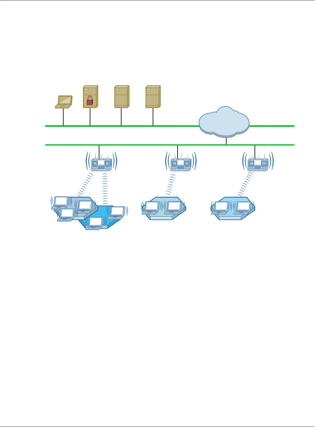
Figure 1 shows how Airgo Networks products operate in concert to create a wireless network.
Figure 1: Airgo Wireless Network
Features Overview
Airgo Access Points extend the range, coverage, and bandwidth of traditional wireless equipment,
while supporting the latest network security and management features. The following are key
features of the Airgo Access Point:
•Standards - Supports IEEE 802.11 and RFC standards
• Supports IEEE 802.11a, b, g, d, e, f, and i standards (or draft standards).
• Supports numerous IETF RFC networking and security standards
• Dual radio or single radio operating in 802.11b/g or 802.11a mode
• Optional enhanced, True MIMI™ data rates up to 108 Mbps
• Requires fewer access-points due to extended coverage and high performance
Client(s)
DNS & DHCP
Server
RADIUS
Server
Access
Point
Wireless Clients
Wireless Clients Wireless Clients
Access
Point
Access
Point
Enterprise
Network
A0001D
NMS
Server

Features Overview
Installation and User Guide: Airgo Access Point 3
•Security - Financial Grade Security
• Four-layers of security: AP security, Admin User Security, Wireless User Security, and
Guest User security support
— AP Security with a built-in unique X.509 AP certificate for constructing a secure
wireless network.
— Admin User Security with management access through SSH, HTTPs and SNMPv3.
— Wireless User Security supports IEEE 802.1X security with WPA-PSK, WPA-EAP,
WEP-64, WEP-128, EAP-TLS, EAP-PEAP, EAP-TTLS, MAC-ACL, Guest
Authentication and Open authentication
— Guest User Security with secure web browser based security
• Wire-speed AES-CCM encryption (supported in hardware)
• Rogue AP detection and monitoring to protect against unauthorized wireless networks
•Wireless Services - Self-Healing and High-Performance Wireless Access
• Each radio is dual-band and multi-mode with 802.11a, b or g operations.
• Dynamic channel assignment
• Support for low, medium or high network density for varying cell size
• World-mode support for compliance for channel and transmit-power constraints in different
countries
• Multiple SSID with Virtual AP feature set
• WMM QOS, or IEEE 802.11e QOS support
• Wireless backhaul to extend secure wireless network without need to wire every access-point
to Ethernet backbone.
•Layer-2 and Layer-3 Mobility - Seamless Mobility
• Supports seamless Layer-2 or intra-IP subnet roaming using IAPP
• Supports seamless Layer-3 or inter-IP subnet roaming using VLANs or Tunneling methods
•Zero-Configuration - Rapid Secure Network Deployment
• Built-in network management and security portal services to enable centralized
configuration, security and management of wireless network.
• Built-in RADIUS server to provide WPA-EAP with certificate based security for wireless
users
• Support RADIUS-proxy to simplify configuration of external RADIUS servers
• Support for legacy station authentication using MAC-address based Access Control List
(ACL).
• Support for password-based Guest-Access authentication
• Policy based configuration of network from NM-Portal AP
• One click software distribution to entire network from NM-Portal AP
• Configuration backup and restore
• Centralized fault-monitoring using Alarms and SYSLOG
• Configuration using CLI, SNMP and Web User-Interface
•Networking - High Performance QOS & VLAN Support
• High-performance bridging, VLANs and static IP routing support
• Extensive QOS support using WMM, IP DSCP, IP Precedence, and IP Protocol with ingress
and egress QOS rules
• Layer-2 Filtering on ingress and egress interfaces.

1 Overview
4 Installation and User Guide: Airgo Access Point
Radio Resource Management
The Airgo AP supports management of radio channels, cell size, and range.
Channel management features include automatic channel selection, support for international
channel sets, dynamic channel changes in response to network conditions, and the ability to assign
channels manually to fine tune channel quality. Cell size and range capabilities enable you to
optimize equipment placement, eliminate dead spots, and reduce interference.
Mobility Management
Mobility management features include Layer-2 and Layer-3 roaming, as users move from one
access point coverage area to another or are switched for load balancing purposes. Layer-2 roaming
occurs by default when a wireless client roams between APs on the same subnet, if 802.11f-based
Inter-Access Point Protocol (IAPP) is enabled. The Layer-3 Mobility feature provides seamless
roaming for wireless clients across multiple subnets in proximity to each other.
Portal Architecture
To support the range of network sizes and configurations served by Airgo Networks products,
Airgo has designed a built-in, flexible, portal services architecture for management and security.
An AP can be configured as an NM Portal AP to support the following services:
Figure 2 illustrates portal services within the Airgo Networks network. NM Portal provides overall
network management functionality and monitoring. The enrollment portal feature enables
verification of additional APs and authorization for operation in the network. The security portal
feature verifies the identity of individual users wanting access to the network.
Service Description
Management NM Portal services provide network management functionality for small to
mid-size wireless networks. Each Airgo AP configured as an NM Portal can
operate in stand-alone mode to provide network management for the entire
network or as a location or branch manager working in conjunction with NMS
Pro, the Airgo Networks Professional Network Management System.
Security Security portal services include support for secure user authentication by way
of a RADIUS server internal to the Airgo AP. Security portal services are part
of NM Portal, but can also be configured independently for backup
authentication in the event that the primary internal RADIUS server becomes
unavailable.
Enrollment Each Airgo Networks wireless network requires an enrollment server to verify
the identity other of Airgo APs and authorize them for operation in the
network. The enrollment portal feature is automatically enabled in the access
point as part of NM Portal. NM Portal should be used for enrollment unless
NMS Pro has been implemented as an enterprise network management
solution.

Features Overview
Installation and User Guide: Airgo Access Point 5
Figure 2: Portal Services
Regardless of network size, configuring one or more Airgo APs as NM Portals yields the following
benefits:
•Even with as few as two APs in a network, NM Portal offers a single point of focus for
monitoring the network and managing security. Configuring the first installed AP as an NM
Portal makes it easy to enroll additional APs.
•The configuration of the NM Portal AP is easily distributed to the other APs in the network,
assuring consistent application of configuration parameters.
•NM Portal can provide user authentication services for an entire small to mid-size network or
serve as a backup security server if an external RADIUS authentication service is used.
Security
Airgo Networks offers a comprehensive security solution that adheres to the following industry
standards and draft standards:
•Data encryption — WEP, Wi-Fi Protected Access (WPA) with TKIP or AES encryption
•User authentication — IEEE 802.1x authentication, including EAP-PEAP or EAP-TLS, WPA-
PSK
•Key management — Microsoft-IAS, FUNK-RADIUS, Airgo Networks NMS Pro, Airgo
Networks integrated security portal, and manual key management capabilities
These features are part of a security architecture that provides the wireless network a greater degree
of security than most traditional wired networks. The following security features are included in all
Airgo Access Points:
•Built-in maximum industry-standard security
•Auto-detection of the security capability of clients and APs
•Policy-based configuration of security settings
•Hardware support for high-performance encryption
•Support for installations ranging from the small-office/home-office (SOHO) to multi-site
enterprises
•Zone privacy to protect users in public hot spots by isolating client stations from each other
•Command-line access using SSH (secure shell)
•Web-based management interface and policy-based management using HTTPS (SSL)
A0028B
NM Portal:
Manage and
Monitor the
Network
Other APs
Enrollment Portal:
Verify AP Identity
Security Portal:
Authenticate Clients

1 Overview
6 Installation and User Guide: Airgo Access Point
•SNMP management interface through SNMPv3
•IEEE 802.11i standards
•User-authentication using EAP-TLS, EAP-PEAP, WPA-PSK, WEP
•Rogue AP detection
•Rogue client detection
VLANs
By decoupling traffic flow and network services from the physical network topology, virtual LANs
(VLANs) enable enterprises to improve network traffic flow, increase load, and deliver varying
levels of service and access to different groups of users. The Airgo AP VLAN feature readily
extends an existing wired VLAN structure to the wireless network. It can also be used to implement
new network privileges and services; for example, user VLANs are integral to the Airgo Networks
guest access feature (see “Guest Access” on page 7).
Airgo supports interface-based VLANs and user-based VLANs. Interface VLANs separate traffic
according to the Ethernet and radio interfaces on the Airgo AP. Packets destined for a specific
interface VLAN are directed to the port with that VLAN assigned. By contrast, user VLANs
separate traffic according to user groups. Users can be assigned to the same VLAN even if they are
in different physical LANs and at geographically dispersed locations. User VLANs are useful for
managing enterprise work groups and differentiating among categories of users. The Airgo Access
Point supports up to 16 VLANs, including a default VLAN.
Quality of Service
Quality of Service (QoS) features enable differential treatment of network traffic types to support
special applications or extend priority access to designated groups of users. For example,
applications such as streaming media and voice over IP (VoIP) suffer serious quality degradation if
data transmission is interrupted or bandwidth fluctuates excessively. You can assign higher service
quality to applications of this type, while maintaining adequate service for less intensive
applications such as print and file sharing. Network utilization is increased with little to no negative
effect on user productivity. QoS can also be used to lower the priority for non-critical applications.
For example, FTP transfers, which are generally not time critical but can consume significant
network bandwidth, can be assigned lower priority than streaming media applications or database
transactions.
QoS can also be assigned on a user group basis. For example, network administrators can be
assigned a higher service quality than other employees, thereby enhancing their ability to manage
and troubleshoot a heavily loaded network.
Airgo Networks implements QoS features using classes of service (COS). Eight COS levels are
available for assignment according to user, group, or application based rules. The COS approach
does not guarantee bandwidth, but it does give “best effort” priority according to the assigned level.
A flexible approach to service quality, it scales easily and accommodates a variety of mapping
rules. MAC layer mappings for COS levels and COS-to-IP layer mappings are supported, and
priority settings can be assigned for different COS mapping rules.
IP Routing
IP routing adds flexibility to AP management and expands the addressing capability of the AP. You
can specify static IP addresses outside the local subnet along with routing information to reach
those addresses.

Standards and Data Rates
Installation and User Guide: Airgo Access Point 7
Multiple SSIDs
The Airgo AP supports multiple SSIDs within each individual AP. Using the multiple SSID
feature, users can access separate networks through a single physical infrastructure. For example, if
you want to create different levels of resource access for employees and visitors, you can create two
SSIDs, one with high security and one with open security.
Guest Access
The Airgo AP supports flexible, secure management of guest access at corporate and hot spot
locations. By contrast with most other guest access solutions, the Airgo AP supports guest access
without necessarily requiring changes to the physical network topology. VLAN tags on the existing
access points segregate users into non-guest and guest VLANs, and guests are automatically
directed to an internal or external web landing page. Guest passwords can be assigned statically or
change dynamically according to a pre-set schedule. An open access option is available to provide
unauthenticated guests with access to an open subnet.
Rogue AP Detection and Classification
Maintaining a secure wireless network requires ongoing monitoring of potential rogue access
points and the ability to classify them as known to the local or neighboring network, or as true
rogues. The network management functions of NM Portal include automatic network scanning and
display of detected APs that potentially qualify as rogues. Using the information included in the
display, network administrators can identify and classify the known APs. The remaining APs are
classified as rogues. By examining the information available for each rogue AP, it is generally
possible to pinpoint the location of the rogue and take action to remove it from the network.
Standards and Data Rates
Airgo Networks supports the wireless networking standards shown in Table 2.
Table 2: Supported Wireless Networking Standards
Standard Area Status
IEEE 802.11b Wireless LAN Approved Standard
IEEE 802.11a Wireless LAN Approved Standard
IEEE 802.11g Wireless LAN Approved Standard
IEEE 802.11d World Mode Support Approved Standard
IEEE 802.11e HCF & eDCF Draft Standard
IEEE 802.11f Inter-AP Protocol (IAPP) Draft Standard
IEEE 802.11h TPC and DFS additional regulatory domains Approved Standard
IEEE 802.11i Wireless Security Approved Standard
IETF Standards Security EAP-TLS Draft Standard
Microsoft Standard Security EAP-PEAP Draft Standard
IETF SNMP MIBs Numerous RFC MIBs Standard
IETF Protocols Bridging, Routing Standard

1 Overview
8 Installation and User Guide: Airgo Access Point
The 802.11 standard specifies the following data rates:
•802.11b: DSSS (1, 2, 5.5 and 11 Mbps)
•802.11a: OFDM (6, 9, 12, 18, 24, 36, 48, 54 Mbps)
•802.11g: OFDM (6, 9, 12, 18, 24, 36, 48, 54 Mbps)
Airgo Networks also offers enhanced, True MIMO™ data rates of 72, 96, and 108 Mbps for
enhanced performance.
Integration with the Existing Wired Network
Airgo Networks wireless networking solutions are standards-compliant to ensure seamless
integration with existing wired network infrastructures. The following integration features are
included with all Airgo APs:
•10/100 Ethernet connectivity
•802.1Q VLAN support
•802.1p QoS support
•Layer-2 and Layer-3 QoS
•802.3af Power-over-Ethernet support
•DHCP server and client support
•NTP for time-synchronization
Management Interface Options
Management support for the Airgo AP is available through four different interfaces:
WPA Security Standard Standard
Wi-Fi Alliance Wireless Interoperability Certification
Table 2: Supported Wireless Networking Standards
Standard Area Status
Interface Description
Web Browser Interface This is the primary user interface for basic and advanced AP
configuration support for a single AP. This guide presents all
configuration tasks using the web browser interface.
NM Explorer A built-in NM Portal web interface is available to manage multiple APs.
For details on using NM Portal, see Chapter 9, “Managing the Network.”
Command Line
Interface (CLI)
The command line interface (CLI) for the Airgo AP is accessible through
a local 9-pin serial console port or over SSH. For more information on
using the CLI to configure the AP, see Appendix A, “Using the
Command Line Interface.”
NMS Pro The NMS Pro user interface provides access to AP configuration
functions and is designed to manage very large numbers of access points
and networks. For more information, see the NMS Pro Installation and
User Guide.

Installation and User Guide: Airgo Access Point 9
2Planning Your Installation
This chapter provides guidelines on planning a wireless network. It includes example network
configurations and explains how to plan for coverage, capacity, security, and network management.
The chapter includes the following topics:
•Introduction
•Assessing Coverage and Capacity Requirements
•Assessing Security Needs and Architecture
•Planning Network Features
•Sample Deployment Scenarios
Introduction
Careful planning of a new wireless network can greatly enhance your ability to install, maintain,
manage, and expand the network. There are several dimensions to installation planning:
•Coverage and capacity requirements — Identify the number and types of access points to
install and determine optimal placement.
•Security needs — Choose a security architecture and features.
•Network management — Choose a method to manage the network and monitor its health.
•Network features — Determine VLAN assignment, user groups, services, and privileges.
If planned properly, a wireless network can be easily expanded and adjusted to changing conditions
and requirements while preserving effective security and enabling network-wide management
support.
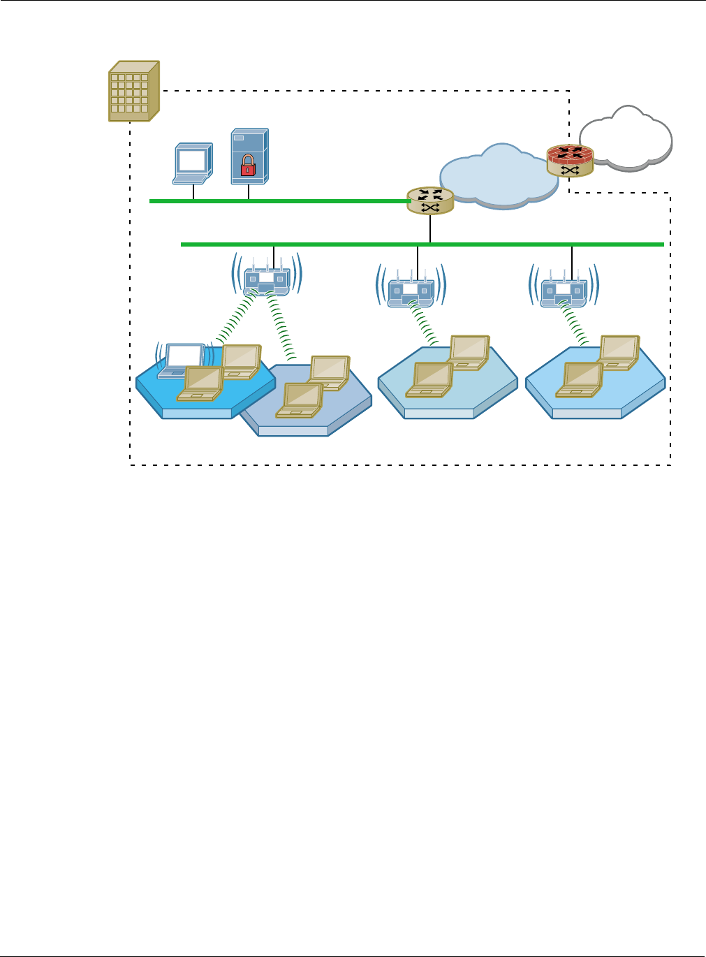
Example Wireless Network Installation
Figure 3 shows the elements of a typical Airgo wireless network. Airgo Access Points provide
wireless connectivity to client stations (laptop or desktop computers) and connect in turn to the
existing wired network infrastructure and beyond to the Internet. Network size and complexity may
also dictate the need for an external RADIUS server for user authentication, as well as installation
of Airgo Networks NMS Pro for enterprise network management.
2 Planning Your Installation
10 Installation and User Guide: Airgo Access Point
Figure 3: Typical Wireless Network
Assessing Coverage and Capacity Requirements
Airgo Networks wireless technology significantly increases wireless coverage or capacity in
comparison to other wireless LAN products. This wireless advantage allows an access point to
service a large area or provide higher data rates, depending upon the conditions at your location.
Figure 4 illustrates the contrast between typical wireless coverage and Airgo wireless coverage.
Each Airgo AP can service a wider area or provide higher data rates than alternative solutions.
Precise coverage and capacity vary considerably depending on factors such as the specific 802.11
protocol being used, antenna placement and location, building construction materials, and local
obstructions.
Enterprise Boundry
NMS RADIUS
10/100 Ethernet
Corporate
Network
Internet
LAN Switch/Router
WAN Router
with Firewall
Network Operations Center
AP with
2 Radios AP with
1 Radio
AP with
1 Radio
802.11a
802.11g/b
802.11a
(or 802.11g/b)
802.11g/b
(or 802.11a)
A0008C

Assessing Security Needs and Architecture
Installation and User Guide: Airgo Access Point 11
Figure 4: Airgo AP Coverage Compared with Other Access Points
Site Surveys
Site surveys are used to measure the wireless characteristics of the physical environment and
thereby determine cost-efficient placement of equipment in the network. They are useful because
physical attributes of a location may have a significant impact on realized coverage and data rates.
The site survey involves a detailed assessment of the radio signal environment of the site based on
experiments and testing. After the wireless network equipment is installed, radio signals are sent
between the AP and a mobile client (laptop) to effectively tune the placement of APs.
A professional site survey is highly recommended for large installations, but can be an expensive
and time-consuming process, especially for installations with a variety of buildings and building
materials, radio signal conditions, and restrictions on equipment placement. Thanks to the dramatic
improvements in capacity and coverage provided by Airgo APs, many small to mid-size companies
can forgo the traditional site survey process and rely instead on general guidelines.
Assessing Security Needs and Architecture
The latest security innovations and standards make it possible to provide complete and effective
security for wireless networks. The specifics of an optimal security solution will vary according to
the type and size of organization. For each environment, Airgo offers a selection of features to
satisfy all your security needs.
Three aspects of security require planning and decisions:
•Enrollment — Specifying the Airgo AP or NMS Pro server used to verify which access points
are authorized to be part of the wireless network.
108 Mbps
54 Mbps
Access Point
Location
Typical
Wireless Coverage
Legacy
Coverage
Coverage
Data
Rate
Legacy
Wireless
Coverage
A0020A

2 Planning Your Installation
12 Installation and User Guide: Airgo Access Point
•Data encryption — Specifying the method of security for wireless data communications
between client stations and the AP.
•Authentication — Specifying the method to verify the identity of users who want to access the
wireless network, and assign access restrictions and services to them.
Enrollment
Enrollment is the process of verifying the identity of APs and confirming that they are authorized to
be a legitimate part of the wireless network. It is recommended that you designate a single
enrollment server for the entire network. For small and mid-size networks, this should be an AP
configured as an NM Portal (see “Selecting a Network Management Method” on page 12). For
large offices and campuses, it is recommended that you use the enrollment module within NMS Pro
as the enrollment server. The process of enrollment is discussed in “Enrolling APs” on page 181.
Data Encryption
Data encryption is the process whereby data packets are encoded to prevent intruders from
deciphering the content. The first wave of IEEE 802.11 products introduced encryption based on
the Wired Equivalent Privacy (WEP) standard. The WEP algorithm uses keys configured on the AP
and in the user client software to encrypt wireless data. Unfortunately, WEP is vulnerable to
compromise and difficult to manage and configure. Temporal Key Integrity Protocol (TKIP) is the
secure successor to WEP.
The current state of the art for data encryption is the Advanced Encryption Standard (AES),
adopted by the Wi-Fi Alliance as part of the IEEE 802.11i working group under the heading Wi-Fi
Protected Access (WPA). The new IEEE 802.11i standard provides financial-grade security with
extremely strong AES over-the-air encryption. The keys used for every user session are unique and
are established automatically using the IEEE 802.1x protocol.
Unless your wireless network must support WEP encryption, using WPA with AES for data
encryption, regardless of your network size or complexity, is recommended.
User Authentication
User authentication is the process of verifying user identity and assigning access rights based on
predetermined rules.
•For small to mid-size networks, the internal RADIUS server within the Airgo AP security
portal provides authentication services across the network. A second AP can also be configured
as a backup security portal.
•For large office and campus installations, one or more external RADIUS authentication servers
may already be in place to provide authentication services for the wired network based on the
IEEE 802.1x RADIUS standard. It is a straightforward exercise to extend that infrastructure to
the wireless network, thereby creating an integrated user authentication process for the entire
enterprise network.
The security portal feature of the Airgo AP plays a special role in wireless backhaul authentication.
For more information, see Chapter 6, “Configuring a Wireless Backhaul.”
Selecting a Network Management Method
As with user authentication, appropriate network management solutions depend upon the size and
complexity of the network, and Airgo products and features are available to support a wide range of
possibilities.

Assessing Security Needs and Architecture
Installation and User Guide: Airgo Access Point 13
•For small and mid-sized networks, configure one of the APs on the network as a portal AP to
provide NM Portal, security portal, and enrollment services, and designate another AP as a
backup for the security portal.
•For large offices and campuses, enterprise-wide control and advanced network management
features become essential to reliable network operations. For these networks, the Airgo NMS
Pro network management application is recommended as a comprehensive network
management solution. Install the NMS server on any suitably configured network computer,
and permit network administrators to obtain access from any designated client station. For
more information, see the Airgo Networks NMS Pro Installation and Configuration Guide.
NMS can be installed as a stand-alone network management solution, or it can be used in
conjunction with NM Portal APs to create an efficient distribution system for network management
data and policies across multiple locations. In enterprises with multiple locations, assign an AP in
each location as the NM Portal. The NM Portal serves an auxiliary function, executing commands
for AP management updates and distributing them to all the APs at the remote location or
collecting data from all the APs at the location and sending the data back to NMS Pro. This model
can significantly reduce the time and network load associated with performing network
management functions such as policy distribution and software updates.

2 Planning Your Installation
14 Installation and User Guide: Airgo Access Point
Planning Network Features
The Airgo AP offers an extensive set of configuration parameters and network service features.
Automated and default options are available for most of these, making it necessary to configure
only a few of the AP parameters to set up a basic network. As needs change, additional features can
be configured to support new network services.
Network feature planning involves the following decisions:
Feature Planning Issues
Physical
Network
Estimate how many APs are expected initially and with growth. Determine whether
wireless backhaul will be required.
Network
Management
Determine the network management structure.
•A network management solution such as NM Portal or NMS Pro is strongly
recommended for all multiple AP installations.
•NM Portal is recommended for small to mid-size networks.
•NMS Pro is recommended for large enterprise networks. NMS Pro can be used in
conjunction with NM Portal for an efficient, hierarchical network management
solution.
•If wireless backhaul is selected, then network management must include NM
Portal.
Authentication Determine how to verify the identity of users requesting access to the network. An
authentication scheme is required for all except open access.
• Pre-shared key (PSK) authentication uses matching keys assigned prior to the
authentication session and stored on the AP and in the client. With PSK, no external
authentication server is required. This approach is useful for small to mid-size
networks in which keys can be easily configured and modified, as needed.
• RADIUS user authentication relies upon individual login and password. This
approach is preferred for medium-large and enterprise networks that must
accommodate sizable, changing user populations. RADIUS is the most common
protocol used in authentication servers.
The Airgo AP can take advantage of the authentication services provided by an
external third party RADIUS server or the internal RADIUS security portal on the
Airgo AP. In conjunction with an external RADIUS server, the security portal
provides wireless backhaul authentication services and can serve as a backup
authentication server if the external RADIUS server is not available.
An authentication zone is a group of one or more RADIUS servers providing user
authentication services within an SSID. If multiple SSIDs are configured, then you
can create an authentication zone for each.
The chosen authentication method influences how services can be configured in the
network.
Security Modes Choose WPA, WEP, or open security modes.
•WPA is recommended, unless WEP is required for communication with legacy
systems.
•WPA security is compatible with WEP and with open security. WEP is not
compatible with open security.
•Guest access requires the open security mode.
•The preferred encryption method is AES, unless TKIP or WEP are required for
compatibility with legacy systems.

Planning Network Features
Installation and User Guide: Airgo Access Point 15
VLAN VLANs permit the network to be segmented according to functional needs without the
restrictions of the physical topology.
•If your enterprise uses multiple VLANS, they can be supported in the wireless
network.
•Multiple VLANs are required for guest access.
SSID Decide whether one or multiple SSIDs will be supported.
•Multiple SSIDs are desirable for applications such as wireless Internet service
(WISP), in which a single physical access point supports multiple user populations
in distinct networks.
•Multiple SSIDs permit support of multiple service levels in networks that rely on
PSK rather than user-based authentication. Services are bound to the SSID rather
than to specific user groups.
Quality of
Service
Quality of Service (QoS) allows you to set priorities for user traffic, thereby increasing
the likelihood that critical data will obtain the needed priority.
•QoS is implemented by way of class of service (COS) mappings. Accept the default
mappings or define custom mappings to create special high or low priority classes
of service.
•Default and custom mappings are compatible with other feature selections.
Service Profile Service profiles specify the services available for an SSID or for designated user
groups within an SSID.
•Accept the default service profile or create custom service profiles to provide
varying levels of service.
•The service profile includes VLAN assignment, COS, and minimum security.
Once created, a service profile can be bound to an SSID with or without a specified
user group.
•If a user group is included in the binding of a service profile to an SSID, then
members of the user group are automatically assigned that profile when
authenticated.
•If no user groups are specified, then all users who access the SSID are assigned the
same profile.
Guest Access Guest access refers to special treatment of users who are not authorized to access the
main corporate network. The guest access feature allows non-authorized users to gain
network access in a controlled way.
Decide whether the network will support guest users and if so, how guest access will
be managed.
•Guest access requires open access security and is not compatible with WEP.
•Guest users can be authenticated by way of an internal or external web landing
page, or can be given open access to a restricted portion of the corporate network.
Feature Planning Issues
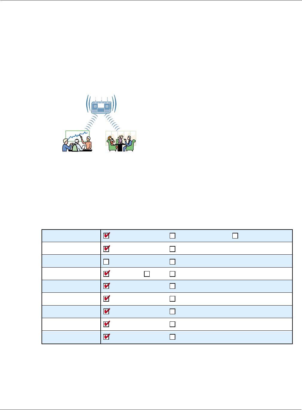
2 Planning Your Installation
16 Installation and User Guide: Airgo Access Point
Sample Deployment Scenarios
This section describes sample feature decisions for companies as a function of network size,
management structure, and network services.
Example 1: Small office, single AP, possible future growth
Acme Works begins as a small company with 20 users. The office is at a single location served by
one access point connected to the wired backbone. The elements of the network are shown in
Figure 5.
Figure 5: Example 1 Network
One AP is able to meet current coverage and capacity needs. The AP is configured as an NM Portal
to assure that the appropriate network management structure will be in place in the event that the
business expands and additional APs are required. Since the user base is small, there is no need for
a RADIUS authentication infrastructure. The security mode is WPA with pre-shared keys (PSK)
and AES encryption. A single SSID is in place, and the default VLAN, QoS, and service profiles
are used.
Figure 6: Example 1 Feature Decisions
A0037C
AP (NM Portal Mode)
A0036A
Physical Network One AP Multiple APs Wireless Backhaul
Network Management NM Portal
Default VLAN
Single SSID (default)
Default COS Mappings Custom COS Mappings
Default Service Profile Custom Service Profiles
Disabled (default) Enabled
Multiple SSIDs
Multiple VLANs
NMS PRO
User Authentication Built-In Security Portal External RADIUS Server
Security Modes WPA (default) Open WEP
VLAN
SSID
Quality of Service
(Class of Service - COS)
Service Profile
Guest Access

Sample Deployment Scenarios
Installation and User Guide: Airgo Access Point 17
The following table lists the tasks required for configuration and provides pointers to the detailed
instructions in this guide.
Table 3: Example 1 Configuration Tasks
Task Process
Bring up the first (or
only) Airgo AP
1Make sure a DHCP server is available on the network, and create a DHCP
reservation for the MAC address of this AP.
2Have the information sheet that was shipped with the AP available.
3Bootstrap the AP as an NM Portal. Defaults are acceptable for most
settings.
4Choose an SSID (wireless network name).
5Choose an administrative password and WPA pre-shared key.
6Configure clients with compatible WPA security using the same pre-
shared key.
References: “Initializing a Normal AP” on page 35 and “Initializing the Portal
AP” on page 38
Confirm that the
network is up
1Open the AP Enrollment panel under the Network Topology menu in NM
Portal to confirm that the AP is listed as enrolled.
2Open the Station Management panel at any time to view a list of client
stations associated to the AP.
References: “Enrolled APs” on page 183 and “Managing Client Stations” on
page 91.
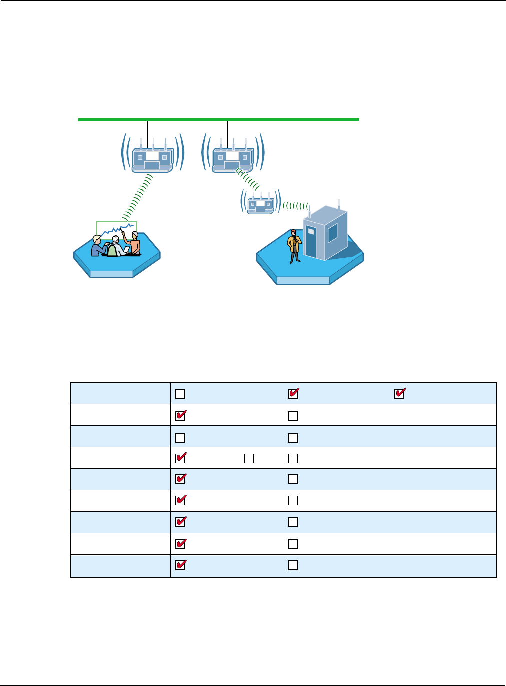
2 Planning Your Installation
18 Installation and User Guide: Airgo Access Point
Example 2: Small to mid-size business with wireless backhaul
Acme Works has now grown to 70 users. The site is the same as in Example 1; however Acme
wants to provide coverage to a temporary building that has no wired connection. An additional AP
is added to provide user access by way of wireless backhaul (Figure 7).
Figure 7: Example 2 Network
Figure 8 summarizes the feature decisions for this example. The security portal capability within
NM Portal provides authentication for the backhaul AP. The security mode is WPA with pre-shared
keys (PSK). A single SSID is in place, and the default VLAN, QoS, and service profiles are used.
Figure 8: Example 2 Feature Decisions
A0042
E
SSID="Corp" SSID="Corp"
10/100 Switched Ethernet
A0036B
Physical Network One AP Multiple APs Wireless Backhaul
Network Management NM Portal
Default VLAN
Single SSID (default)
Default COS Mappings Custom COS Mappings
Default Service Profile Custom Service Profiles
Disabled (default) Enabled
Multiple SSIDs
Multiple VLANs
NMS PRO
User Authentication Built-In Security Portal External RADIUS Server
Security Modes WPA (default) Open WEP
VLAN
SSID
Service Profile
Guest Access
Quality of Service
(Class of Service - COS)

Sample Deployment Scenarios
Installation and User Guide: Airgo Access Point 19
Table 4: Example 2 Configuration Tasks
Task Explanation
Enroll APs 1Connect the additional AP to the wired network.
2Enroll the AP to support wireless backhaul
Reference: “Enrolling APs” on page 181
Distribute policies to
other APs
1Generate the default policy based on the configuration of the NM Portal
AP.
2Distribute the policy to the other AP(s) in the network.
Reference: “Working with Policies” on page 197
Distribute configuration
updates
1Make any configuration changes in the NM Portal AP.
2Regenerate the default policy and redistribute to the enrolled AP(s).
Reference: “Working with Policies” on page 197
Install wireless backhaul
AP
1Disconnect the wireless backhaul AP from the wired network.
2Place the AP where needed, within radio range of the wired AP.
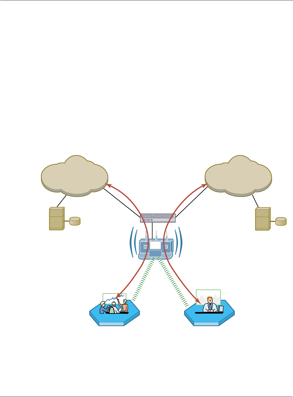
2 Planning Your Installation
20 Installation and User Guide: Airgo Access Point
Example 3: Mid-size business, multiple SSIDs, multiple VLANs
Now a successful business, the management at Acme Works wants to position the company for
continued growth. Management decides to deploy an external RADIUS server to manage user
authentication centrally for the entire company. The RADIUS authentication infrastructure works
well for a changing user population (employees joining, leaving, or moving to new departments)
and readily supports further network service enhancements.
The company creates two SSIDs as a way to separate the Finance department network traffic from
the main corporate network traffic. Two RADIUS servers are configured, each in its own
authentication zone. To separate Finance department traffic from the overall network traffic, a
Finance VLAN is created. A Finance service profile is also created and bound to the Finance SSID.
The service profile is configured to include the Finance VLAN, high security, and higher-than-
normal COS. Once this structure is in place and a member of the Finance group is authenticated by
way of the RADIUS server, the Finance group tag is passed to the Airgo AP, and the Finance
service profile is applied to the user.
The network configuration for this example is shown in Figure 9, and the feature decisions are
shown in Figure 10.
Figure 9: Example 3 Network
RADIUS
Server
RADIU
S
Server
A0044B
Corporate VLAN
Corporate VLAN
VLAN Switch
Finance VLAN
Finance VLAN
Corporate Finance
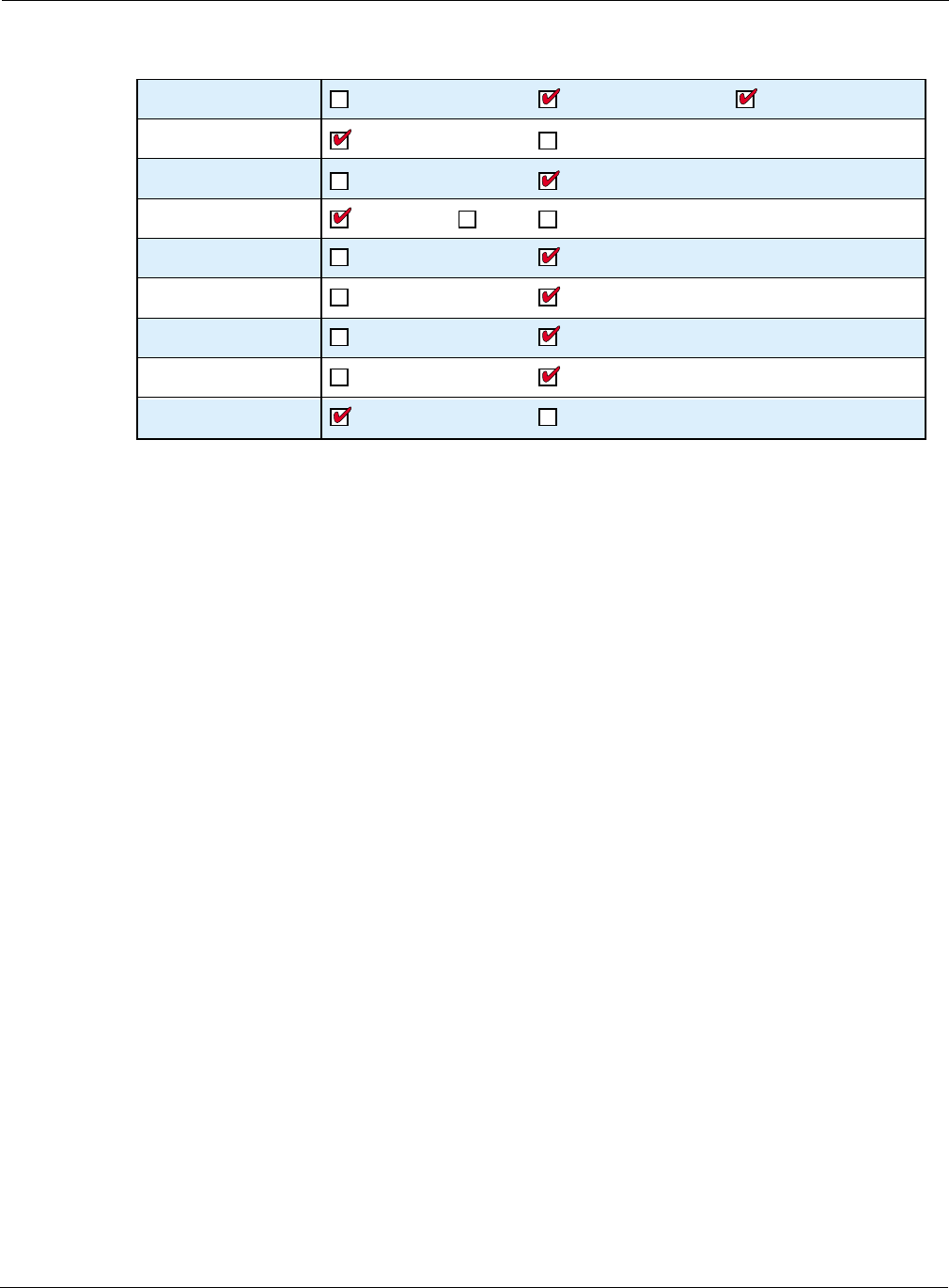
Sample Deployment Scenarios
Installation and User Guide: Airgo Access Point 21
Figure 10: Example 3 Feature Decisions
The following table lists the tasks required to link to an external RADIUS server and add multiple
VLANs, and provides pointers to the detailed instructions in this guide.
Table 5: Example 3 Configuration Tasks
Task Explanation
Add authentication
servers and zones
1Identify the RADIUS server for each authentication zone.
2Select the authentication option for the SSID, with reference to the defined
authentication zone.
References: “Configuring SSID Parameters” on page 83 and “Configuring
Authentication Zones” on page 155
Set up VLANs 1Choose the VLAN structure for the network.
2Configure the VLANs.
Reference: “Configuring VLANs” on page 111
Add VLANs to the
service profiles
1Define or modify service profiles to include VLAN selection.
2Bind each profile to an SSID with an existing or new user group.
Reference: “Profile Table” on page 89 and “SSID Details” on page 87
Distribute configuration
updates
1Make any configuration changes in the NM Portal AP.
2Regenerate the default policy and redistribute to the enrolled AP(s).
Reference: “Working with Policies” on page 197
A0036A
Physical Network One AP Multiple APs Wireless Backhaul
Network Management NM Portal
Default VLAN
Single SSID (default)
Default COS Mappings Custom COS Mappings
Default Service Profile Custom Service Profiles
Disabled (default) Enabled
Multiple SSIDs
Multiple VLANs
NMS PRO
User Authentication Built-In Security Portal External RADIUS Server
Security Modes WPA (default) Open WEP
VLAN
SSID
Service Profile
Guest Access
Quality of Service
(Class of Service - COS)
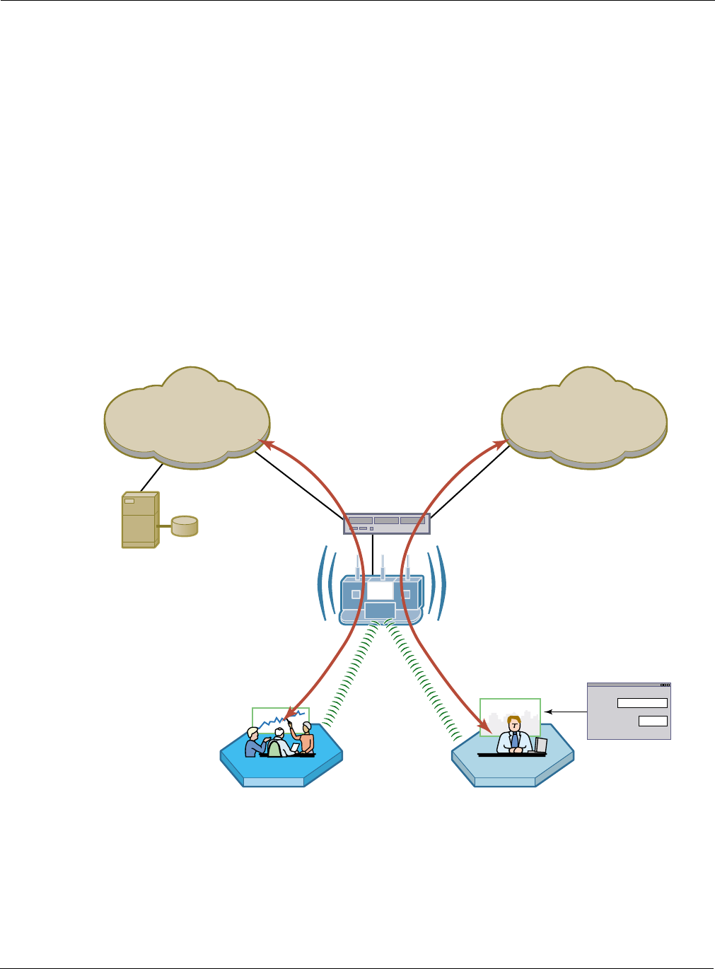
2 Planning Your Installation
22 Installation and User Guide: Airgo Access Point
Example 4: Large business, guest access, extended network services
Acme Works is now a widely known and successful enterprise. With an ever increasing number of
visitors requiring network access, the network administrator decides to implement a corporate guest
access solution.
A guest VLAN and service profile are created and bound to the Corporate SSID, and a guest
password is created. Guests can now visit Acme Works, log in using the guest password through a
web browser, and obtain access to the resources available on the guest VLAN.
As additional needs arise, the network administrator can easily add new VLANs and service
profiles, and change the available levels of service. New VLANs are created to segregate traffic for
the Manufacturing and Engineering departments, and new service profiles are created to
accommodate members of those departments. Special classes of service are assigned for
applications sensitive to interruption or bandwidth fluctuation, such as voice over IP, and low
priority, bandwidth-intensive applications such as FTP transfers.
The network configuration for this example is shown in Figure 11, and the feature decisions are
shown in Figure 12.
Figure 11: Example 4 Network
RADIUS
Server
A0045D
Corp
VLAN
Corp-VLAN
VLAN Switch
Guest
VLAN
Guest-VLAN
Corp Guest Access
Guest
ID
Password

Sample Deployment Scenarios
Installation and User Guide: Airgo Access Point 23
Figure 12: Example 4 Feature Decisions
The following table lists the tasks required to configure guest access and provides pointers to the
detailed instructions in this guide.
Table 6: Example 4 Configuration Tasks
Task Explanation
Set up guest VLANs •Configure a VLAN for guest access.
Reference: “Configuring VLANs” on page 111
Create guest service
profile
•Add a guest service profile with the guest VLAN and desired COS and
open security.
Reference: “Profile Table” on page 89 and “SSID Details” on page 87
Configure landing page •Choose an internal or external landing page and assign guest password.
Reference: “Configuring Guest Access with VLANs” on page 173
Distribute configuration
updates
1Make any configuration changes in the NM Portal AP.
2Regenerate the default policy and redistribute to the enrolled AP(s).
Reference: “Working with Policies” on page 197
A0036A
Physical Network One AP Multiple APs Wireless Backhaul
Network Management NM Portal
Default VLAN
Single SSID (default)
Default COS Mappings Custom COS Mappings
Default Service Profile Custom Service Profiles
Disabled (default) Enabled
Multiple SSIDs
Multiple VLANs
NMS PRO
User Authentication Built-In Security Portal External RADIUS Server
Security Modes WPA (default) Open WEP
VLAN
SSID
Service Profile
Guest Access
Quality of Service
(Class of Service - COS)
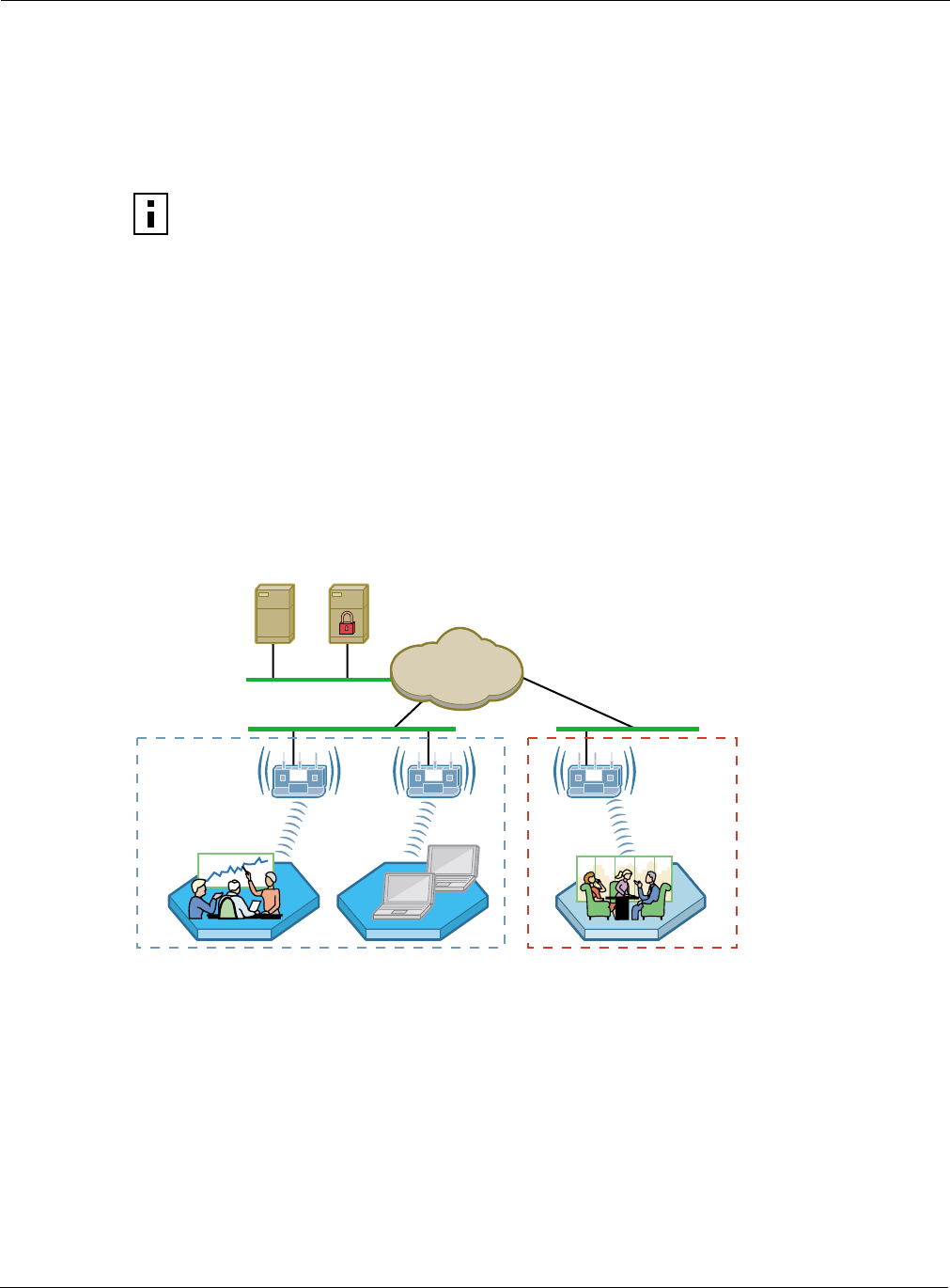
2 Planning Your Installation
24 Installation and User Guide: Airgo Access Point
Example 5: Large Campus with Branch Offices
This example shows how a company can incorporate centralized network management to control a
large campus with branch offices. The company has planned its network to include the NMS Pro
Network Management System. This solution will provide network administrators with extensive
control and oversight, centralized monitoring, and fault management.
The campus buildings and branch offices lend themselves to a hierarchical management structure in
which an NM Portal AP is configured on each building subnet. Each NM Portal AP handles policy
distribution and software upgrades at its location as directed by NMS Pro. The NM Portal AP also
serves as a backup security portal in the event that another RADIUS authentication server in its
authentication zone becomes unavailable.
The network configuration for this example is shown in Figure 13 and the feature decisions are
shown in Figure 14.
Figure 13: Example 5 Network
NOTE: AP configurations must be reset to factory defaults before they can be enrolled
by NMS Pro. For this reason, it is best to make the decision to use NMS during initial
network planning, before APs are installed in the network. For further information, see
“Resetting the Access Point” on page 31 in this guide and also see the NMS Pro
Installation and User Guide.
A0046C
NMS Pro
Server
NM Portal AP
Enterprise
Network
RADIUS
Server
NM Portal AP
Location A Location B

Sample Deployment Scenarios
Installation and User Guide: Airgo Access Point 25
Figure 14: Example 5 Feature Decisions
The following table summarizes the tasks required to provide network management for the campus
installation:
Table 7: Example 5 Configuration Tasks
Task Explanation
Install NMS Pro Reference: NMS Pro Installation and Configuration Guide
Enroll APs •Use the NM Portal in the local building or the campus NMS Pro system to
enroll additional APs.
Reference: “Enrolling APs” on page 181 or the NMS Pro Installation and
Configuration Guide
Create and distribute
policies
•Use NMS Pro to create configuration policies and distribute them to APs
across the network.
Reference: NMS Pro Installation and Configuration Guide
A0036A
Physical Network One AP Multiple APs Wireless Backhaul
Network Management NM Portal
Default VLAN
Single SSID (default)
Default COS Mappings Custom COS Mappings
Default Service Profile Custom Service Profiles
Disabled (default) Enabled
Multiple SSIDs
Multiple VLANs
NMS PRO
User Authentication Built-In Security Portal External RADIUS Server
Security Modes WPA (default) Open WEP
VLAN
SSID
Service Profile
Guest Access
Quality of Service
(Class of Service - COS)

2 Planning Your Installation
26 Installation and User Guide: Airgo Access Point

Installation and User Guide: Airgo Access Point 27
3Installing the Access Point Using the
Configuration Interfaces
This chapter explains how to install and quickly configure the Airgo Access Point and provides
instructions for accessing the web and command line interfaces. The chapter includes the following
topics:
•Hardware Components
•System Requirements
•Installation Requirements
•Installing the Access Point
•Using the Configuration Interfaces
•Using AP Quick Start to Initialize the Access Point
•Navigating the Web Interface
•Configuration Wizards
Hardware Components
The Airgo Access Point shipping package contains the following items:
•Airgo Access Point
•Power supply and separate AC cord
•Software and documentation
System Requirements
The following are required to connect to the Airgo Access Point:
•For web browser or network management portal access, a computer with a web browser
capable of secure HTTP connections (HTTPS)
•For SSH connection, a computer with an SSH utility (the PuTTY application meets this
requirement and is available as freeware)
•10/100 Ethernet cable to connect to the AP
The computer designated for AP access should be located on the same Local Area Network (LAN),
with a compatible IP address and subnet mask, or it must be able to be routed to the AP.
To connect directly to the console port in order to access the command line interface, have the
following available:
•A 9-pin DCE female-to-female null modem connector to connect the PC to the Access Point
•Terminal emulator software
Installation Requirements
Airgo Access Points are radio-frequency devices and are therefore susceptible to RF interference
and obstructions. When selecting locations for AP placement, try to choose places free of large

3 Installing the Access Point Using the Configuration Interfaces
28 Installation and User Guide: Airgo Access Point
metallic structures such as equipment racks, steel bookcases, or filing cabinets, and locations not
crowded by computer enclosures.
If using an external antenna with the AP (optional), try to place the unit as high as possible, where
it is free of obstruction. Install the AP away from sources of RF interference, such as microwave
ovens, cordless phones, electric motors, and similar appliances.
Power and Cabling Requirements
The following equipment is required to install the Airgo Access Point:
•AC power outlet (100-240V, 50-60Hz standard) to power the AP (a surge-protected power
supply is recommended)
•RJ-45 port on a standard 10/100BaseT Ethernet device (hub, switch, router, or similar device),
if connecting to a wired network
•Industry standard Category 5 UTP Ethernet cables
•9-pin-to-9-pin DCE serial null modem cable or serial-to-USB cable if connecting the console
Network Information Requirements
Have the following information accessible before configuring the AP:
•IP address assigned to the AP (fixed IP address or DHCP-reserved address)
•IP addresses for the default gateway, DNS server, and NTP server if DHCP is not used to
provide IP addresses
•IP address of the SMTP email server if the AP is to send alerts to a specified email address
•Email address of the administrator who will receive the alerts
Installing the Access Point
Follow these steps to install the Airgo Access Point:
1Connect the Ethernet cable to the RJ-45 Ethernet connector on the AP (see Figure 15).
2Plug the other end of the Ethernet cable into an available Ethernet port on your wired network.
3(Optional) If an external antenna is to be used, attach it to the AP. Place or mount the antenna in
an unobstructed location.
4Plug the AC power cable into the power module.
5Plug the other end of the AC power cable into an approved three-prong grounded outlet (surge-
protected and/or UPS is recommended).
6Connect the power module connector to the power connector on the AP.
The Airgo Access Point powers up automatically.

Installing the Access Point
Installation and User Guide: Airgo Access Point 29
Figure 15: Airgo AP Connections
Using Power Over Ethernet
Power-over-Ethernet (PoE), based on the 802.3af standard, can be used to supply power to the
Airgo AP. If both DC power and PoE are used at the same time, then failover takes place
automatically in the event that one of the power sources is lost. For failover, the following rules
apply:
•The AP uses the power source with the highest voltage.
•Unplugging either cable causes power to switch automatically to the other source, which may
cause the AP to reboot.
Placement and Orientation
Make sure that the Airgo AP is positioned in an upright position for airflow and antenna placement
(Figure 16).
10/100BaseT
Ethernet port
Default
Reset
A0003
B
Console port
DC power
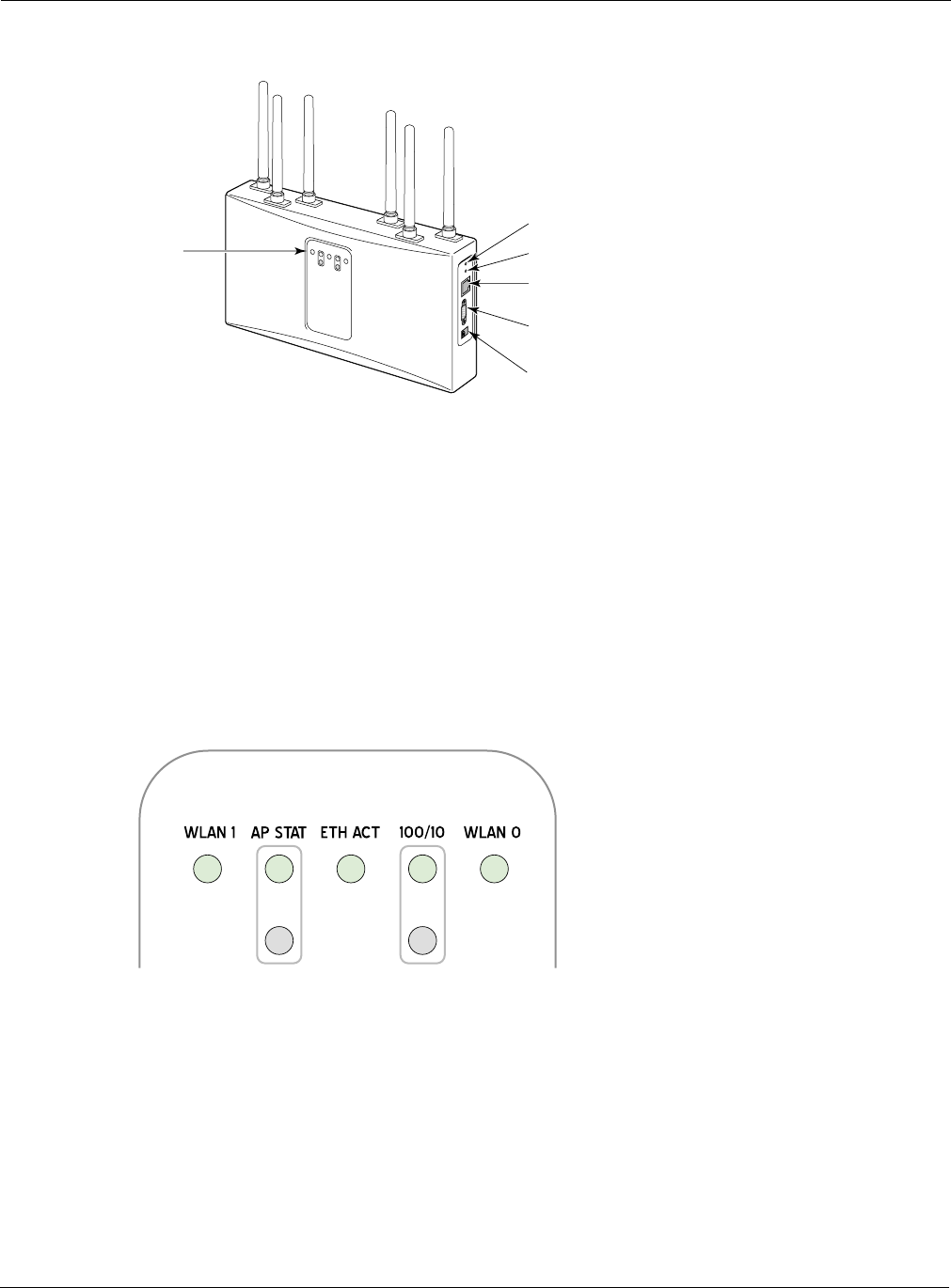
3 Installing the Access Point Using the Configuration Interfaces
30 Installation and User Guide: Airgo Access Point
Figure 16: Airgo AP Placement
Verifying the Installation
To verify the Airgo Access Point is operational, examine the front of the AP.
•Is the status LED red or green? If not, check the power connections and whether the AC outlet
has power.
•(For wired-AP installations) Is the Ethernet connection LED on? If not, check the Ethernet
cable to make sure it is seated securely in both the AP and the network port.
Interpreting the LEDs
Refer to Figure 17 and Table 8 for LED definition.
Figure 17: Airgo AP LEDs
Reset
Default
LEDs
Console port
10/100BaseT
Ethernet port
Power connector
A0002B
A0004A

Installing the Access Point
Installation and User Guide: Airgo Access Point 31
Connecting the Serial Port
Follow these steps to connect a terminal to the serial port for command line interface access:
1Attach a serial null modem cable to the AP (see Figure 15).
2Attach the other end of the cable to the serial port of your computer.
3Use a terminal emulation tool such as HyperTerminal. Configure the terminal as follows:
• 115,200 BAUD
• 8-bits
• No parity
• 1 stop bit
• No flow control
A command prompt should now be available to access the command line interface.
Resetting the Access Point
Reset the AP in any of the following ways. If the AP has a buzzer installed, the AP beeps once
when reset. If the AP has a buzzer installed and is reset to factory defaults, then the AP beeps twice
when booted.
Table 8: LED Definitions
LED Description
WLAN1 Blinks green for activity.
AP STAT Two AP status LEDs indicate the AP status. When the AP is reset or powered
on, the bottom LED turns red and then the top LED blinks green. Once the AP
successfully boots up, the top LED turns green and stays green.
When the AP is reset to defaults, the LEDs light up in the same sequence as
described above. If the AP has a buzzer installed, two short beeps indicate that
the AP is being reset to defaults.
ETH ACT Blinks green for activity.
100/10 Indicates Ethernet Link. Two LEDs. Only one of them will be lit up at a time.
•Top LED: 100BT Link – Lights up green when 100Mbit link is
established. Off means no link on 100Mbit.
•Bottom LED: 10BT Link – Lights up yellow when 10Mbit link is
established. Off means no link on 10Mbit.
WLAN0 Blinks green for activity.
Method Description
Web browser interface Use the Configuration Management panel under System Configuration. See
“Reset Configuration” on page 249.
Reset button Press the reset button on the side of the AP.
Power down Power down the AP by disconnecting the power cable (not recommended).

3 Installing the Access Point Using the Configuration Interfaces
32 Installation and User Guide: Airgo Access Point
Reset the configuration of the AP to the factory default in any of the following ways:
Factory Default Settings
Each AP is shipped with the following factory default settings:
Method Description
Web browser
interface
Use the Configuration Management panel under System Configuration. See
“Reset Configuration” on page 249.
CLI Use the command sequence:
config
system >
reset-to-defaults factory-defaults
Reset and default
buttons on the AP
This is useful if the administrative password is lost; however, before
performing the reset, make sure to have the original factory-assigned AP
password available. Follow these steps:
1Make sure the AP is connected to power (power adaptor or Power-over-
Ethernet).
2On the side of the AP, hold down both the Reset and the Default buttons.
The button closest to the antenna is the Reset button. The button below it is
the Default button.
3Release only the Reset button and continue to hold down the Default
button. After 10 seconds, the Status LED blinks from red to green twice. If
the AP has a buzzer, a beep indicates that the restore operation has started.
4Now release the Default button. The AP continues to reboot. The Status
LED turns green when the reboot is successful and the AP is operational.
During this process, all passwords and configurations are reset to factory
defaults. If the AP was previously enrolled in a network, it must be re-
enrolled. The new administrator password is now the original AP unique
password that was set at the factory.
NOTE: The AP configuration may not revert back to factory defaults if the Reset
button is pressed immediately after issuing the reset-to-defaults factory-
defaults command from the CLI or applying the reset function from the AP web
interface (“Reset Configuration” on page 249). To ensure that the configuration reverts
back to factory defaults, allow the reset to defaults operation to reboot the AP
automatically.
Item Description
Password Each AP is shipped with a unique administration password provided in
the paperwork shipped with the AP.
Certificate Thumbprint Each AP internally contains a unique digital certificate and associated
thumbprint (key) included in the paperwork shipped with the AP.
IP Address When an AP boots for first time and is able to access a DHCP server, it
will obtain an IP address. If an AP fails to secure an IP address lease from
a DHCP server, it will default to the IP address of 192.168.1.254.
Each NM Portal AP should have a fixed IP address.

Using the Configuration Interfaces
Installation and User Guide: Airgo Access Point 33
Using the Configuration Interfaces
Four different secure interfaces are available for administering the Airgo Access Point:
•Web browser (https)
•Command line interface (SSH or console)
•SNMP (SNMPv3)
•Policy management (https, XML-based)
This section explains how to access each of these interfaces. The configuration procedures in this
guide are all presented using the web browser interface. For additional information on the CLI, see
the CLI Reference Manual.
Using the Web Browser Interface
The Airgo AP web browser interface is the easiest way to configure an AP or check the current
settings. It includes the QuickStart facility to get the AP running as quickly as possible with a full
set of AP features. NM Portal can also be launched from the web interface.
To connect to the AP using the web browser interface requires an IP connection to the AP network
and a computer with a browser capable of Secure Sockets Layer (SSL) connections. Follow these
steps:
1Launch the web browser.
aIf your network has a DHCP server, enter the DHCP-assigned address of the AP in the
address bar.
bIf your network does not use a DHCP server, assign the static address 192.168.1.1/24
to your computer, and then enter https://192.168.1.254 in the browser address bar.
2Depending on the browser security settings, a security alert may open with a prompt on
whether to accept the Airgo Networks security certificate. Click Yes to accept the certificate
and to open the login panel.
3In the login panel, enter or confirm the administrative username, enter the password, select a
language, and click OK to open the web interface. The factory default for administrator access
is username: admin. If the AP has not been initialized, the username field is grayed out. The
Security Mode The default security mode for the AP is WPA-PSK authentication with
AES encryption.
Radio Configuration The default global configuration for radio settings is “US, Indoor,” which
allows operation in all twelve IEEE 802.11a channels. “US, Any” permits
operation only in the middle and upper UNII bands (8 channels) for IEEE
802.11a (5GHz) operation.
Item (continued) Description
NOTE: In the web interface, a red asterisk (*) next to a field name indicates that the field is
required. Error messages are presented in text near the top of the panel below the
information box.
NOTE: Each AP has DHCP enabled by default. If you are installing the AP on a
network that already has a DHCP server, enter the DHCP-assigned address of the AP to
access the web interface.
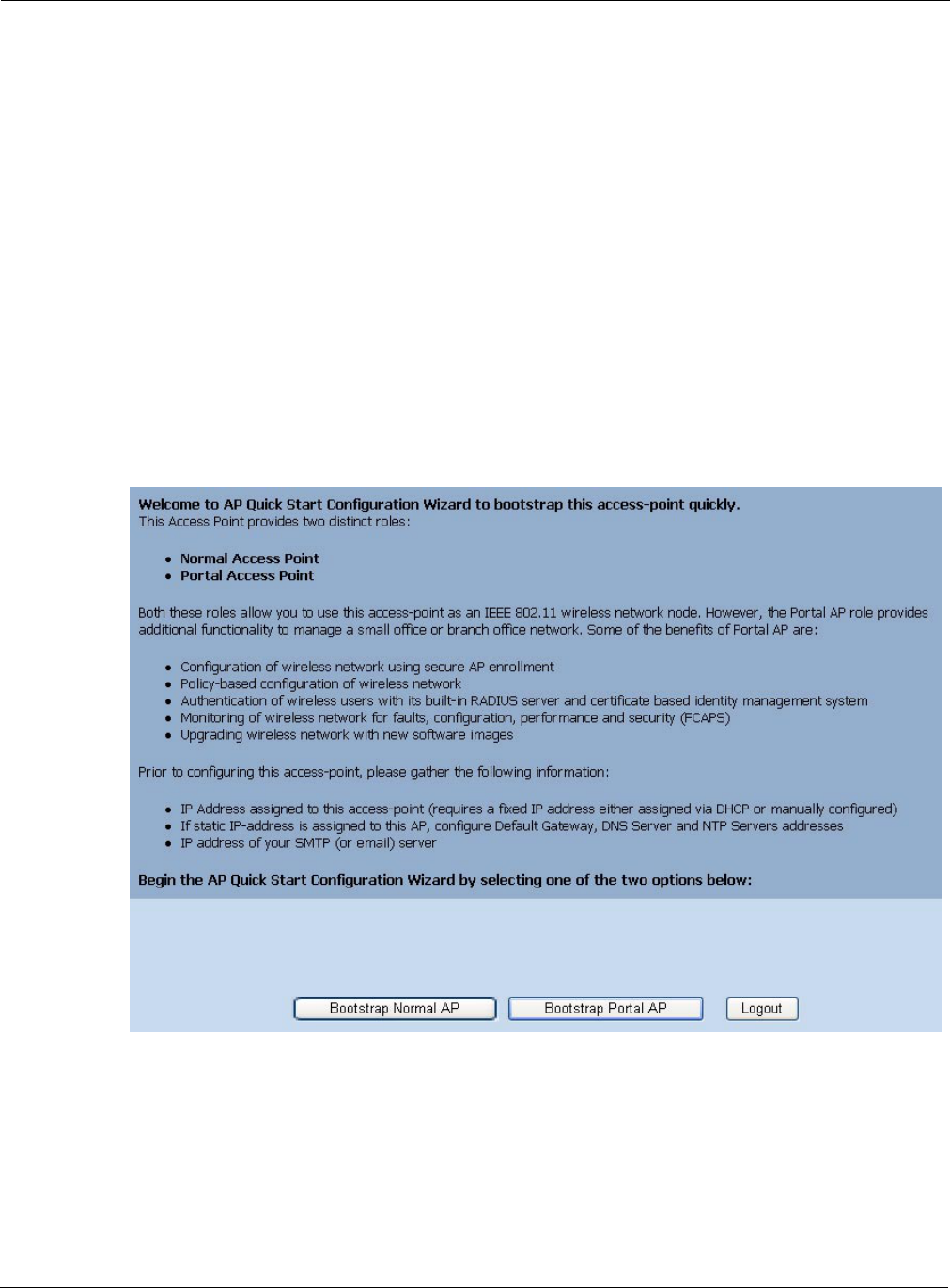
3 Installing the Access Point Using the Configuration Interfaces
34 Installation and User Guide: Airgo Access Point
factory default password is shipped with the AP on a paper insert. Use the password from the
insert to log in.
4The system response at this point depends upon whether the AP has already been initialized.
aIf the AP has been initialized, the Home feature panel opens. See “The Home Panel” on
page 40.
bIf the AP has not been initialized, the QuickStart Welcome panel opens. Use the QuickStart
panels described in the next section to quickly configure the AP.
Using AP Quick Start to Initialize the Access Point
When accessing the web interface for the first time or after resetting the AP to factory defaults, the
Welcome panel of the AP Quick Start Wizard opens (Figure 18). From this panel, initialize the AP
in either of two roles:
•Normal Access Point
•Portal Access Point (NM Portal)
Figure 18: AP Quick Start Welcome Panel
Both roles allow the AP to function as an IEEE 802.11 wireless network node. As a portal AP, the
following additional functions are available:
•Configuration of the Airgo Networks wireless network using secure AP enrollment and policy-
based configuration of APs
•Authentication of wireless users via built-in RADIUS server and certificate-based identity
management system
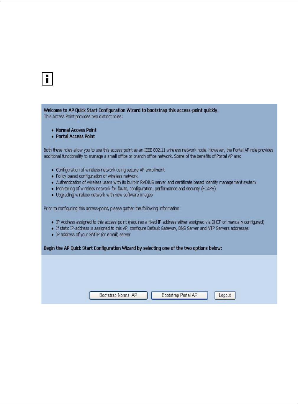
Using AP Quick Start to Initialize the Access Point
Installation and User Guide: Airgo Access Point 35
•Monitoring of Airgo Networks network for faults, configuration alerts, performance, and
security (FCAPS)
•Upgrade of the Airgo AP network with new software images
Initializing a Normal AP
1Click Bootstrap Normal AP from the Quick Start Welcome panel to open the first
initialization panel (Figure 19).
Figure 19: QuickStart Configuration Parameters
The following fields are available on this panel; however, it is not necessary to reset any of
these fields to initialize the AP:
NOTE: Click Logout if it is necessary to leave the Quick Start panels. If you log out
prior to completing the setup process, the settings are not saved.
Field Description
AP Hostname Alphanumeric name for the AP. The factory default for this field is AP
followed by the MAC address of the AP’s Ethernet interface (eth0).
Enable DHCP Assigned
IP Address
Checkbox that indicates whether DHCP is used to obtain an IP address. If the
box is cleared, the static Management IP Address fields are activated; if the
box is selected, the static Management IP Address fields are inactive.
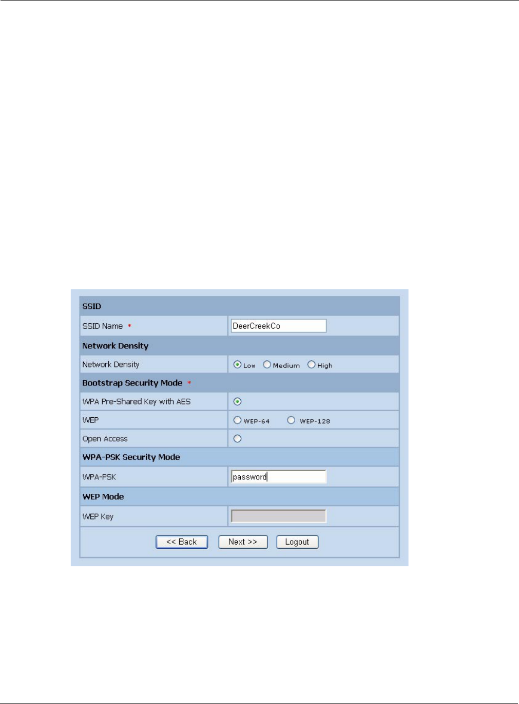
3 Installing the Access Point Using the Configuration Interfaces
36 Installation and User Guide: Airgo Access Point
2Click Next to continue to the next panel (Figure 20). Use this panel to configure network
identity.
Figure 20: QuickStart Network Identity
3Configure the following information on this panel:
IP Address/Maskbits Static IP address and subnet prefix for the AP. Required if the IP address is
not obtained automatically. The default is 192.168.1.254/24.
NOTE: It is required that each NM Portal have a static IP address.
Default Gateway IP address of the gateway to the wired network. Required for complete
network access, if the IP address is not obtained automatically. The default is
the existing network gateway.
Domain Name Servers IP address of the server supplying DNS service. Required for complete
network access, if the IP address is not obtained automatically. The default is
the DNS server for the existing network.
Date Current date in MM/DD/YYYY format
Time Current time in HH:MM:SS format (hours 0-23)
Time Zone US zone or GMT option. For US zone, click the radio button and select a time
zone. For GMT, click the radio button and select an offset in HH:MM format.
Field Description
SSID Name Service set identifier for the network, also known as the Wireless Network
Name. The default name must be changed. (required)
Field Description
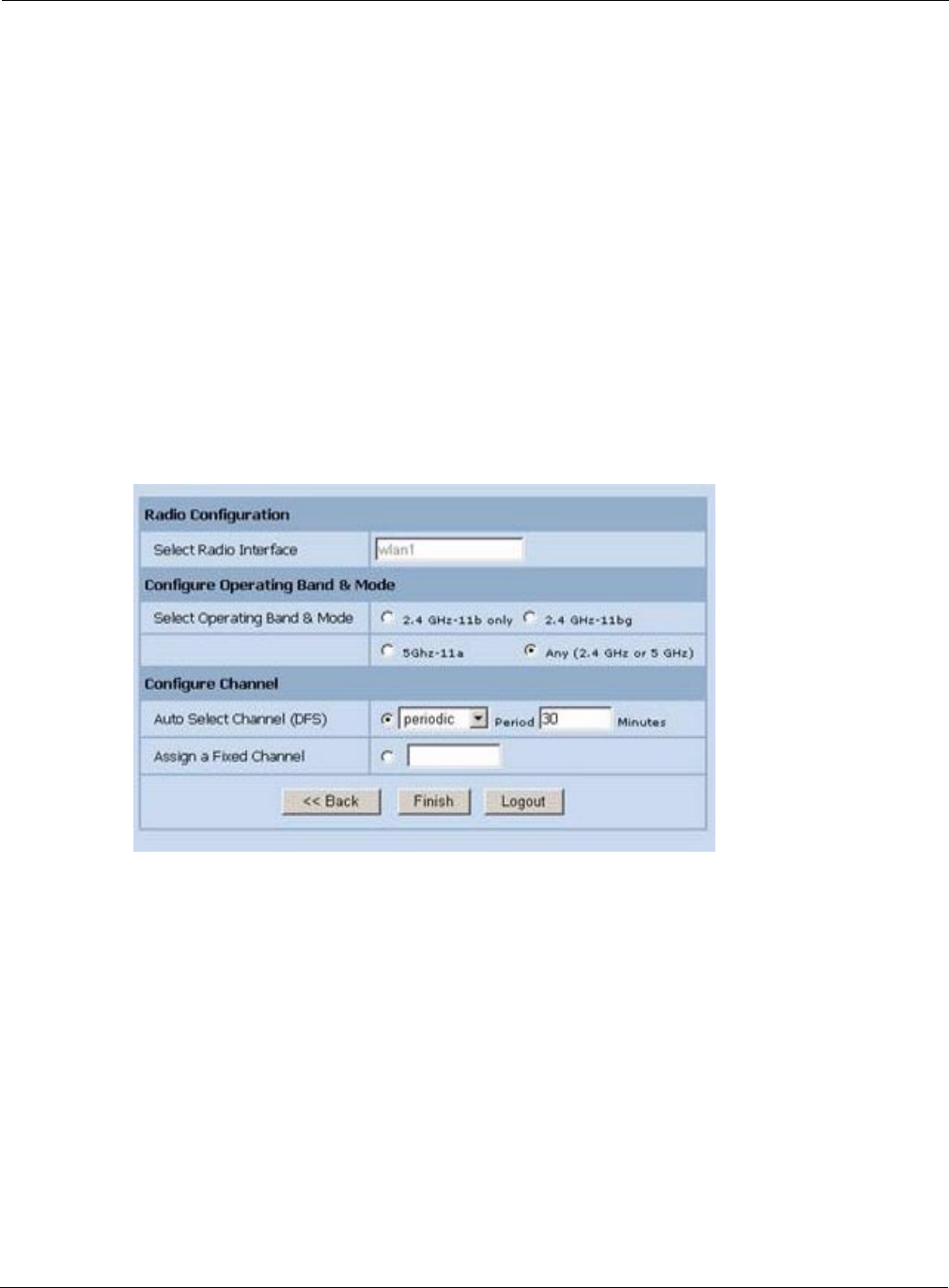
Using AP Quick Start to Initialize the Access Point
Installation and User Guide: Airgo Access Point 37
4Click Next after making selections.
The last two panels (Figure 21) configure up to two radios on the AP. After entering settings on
the first of the two panels, click Next to open the second panel.
Figure 21: QuickStart Radio Parameters
5Set the following information:
Network Density Indicates the proximity of APs to each other. For closely spaced APs that can
support high data rates, select the high density option. For maximum coverage
at lower data rates, select the low density option. The default setting is Low.
Bootstrap Security
Mode
WPA-PSK, WEP-64, WEP-128, or Open security option. The option
determines the security mode for the AP.
WPA-PSK Security
Mode
Activated if WPA is selected as the security mode. Enter a alphanumeric
string at least eight characters in length. (required if security mode is WPA-
PSK)
WEP Key Activated if WEP is selected as the security mode. Enter a WEP key. A WEP-
64 key is 10 hex characters, and a WEP-128 key is 26 hex characters.
(required if security mode is WEP)
Field Description
Select Radio Interface Specific radio to be configured on the AP (wlan0 or wlan1). These correspond
to the WLAN0 and WLAN1 LEDs on the front of the AP.
Select Operating Band
& Mode
802.11b mode in the 2.4GHz band, 802.11b or g mode in the 2.4GHz band,
802.11a mode in the 5GHz band, or auto selection (Any).
Field Description

3 Installing the Access Point Using the Configuration Interfaces
38 Installation and User Guide: Airgo Access Point
6After entering settings for both radios, click Finish to complete the initialization process. (If
initializing a portal AP, as described in the next section, the button is labeled Next.)
Initializing the Portal AP
Using the QuickStart panels to initialize NM Portal is similar to initializing a normal AP. The first
four panels, as described in the previous section, are the same as for the normal AP. When
configuring the second radio, click Next to set the administration and networking configuration
(Figure 22).
Configure Channel Select Auto-Select Channel or Assign Fixed Channel options. In both of these
cases, the channel set used for auto-scanning can also be restricted.
•Auto-Select: Select at-startup to automatically determine the channel when
the AP is booted, or periodic to auto-select the channel at the specified
number of minutes.
•Assign Fixed Channel: Select a static channel.
NOTE: The fixed channel must be a valid channel number, and it must be
compatible with the AP hardware for the country in which the AP is installed. If
an invalid or incompatible channel is assigned, the bootstrapping process can
be completed successfully, but an error message appears to remind the user of
the channel incompatibility. If this occurs, change the channel assignment after
bootstrapping by following the instructions in “Global Configuration” on
page 61. This section includes a table of valid channel settings.
NOTE: The defaults for radio configuration have been selected for the best operational
radio behavior across a variety of environments. Modifying these parameters alters
radio behavior, which may have an impact on network performance or services. For
example, selecting an operating band of 5GHz (802.11a) may prevent legacy client
adapters from associating to the AP.
NOTE: If DHCP is used to assign an IP address to the AP, the lowest MAC address
should be pinned to the fixed IP address.
Field Description
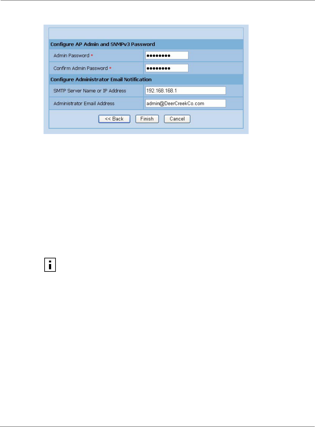
Navigating the Web Interface
Installation and User Guide: Airgo Access Point 39
Figure 22: Portal QuickStart panel
7Enter the following information consistent with your corporate standards:
8Click Finish to complete the initialization process and bring up the AP Explorer Home panel.
The process takes approximately two minutes. When the process is complete, the Home panel
opens.
Navigating the Web Interface
The Airgo AP web interface is divided into three main areas. The menu tree (Figure 23) provides
access to all the panels and features of the web interface. To expand a menu in the menu tree, click
the arrow to the left of the menu name.
Field Description
Admin Password Enter and confirm the password used to manage this AP and other enrolled
APs. The password must be between 8 and 32 characters and is used for local
administrator login and SNMP v3 login. (required)
SMTP Server Name or
IP Address
Address of your SMTP server
Administrator Email
Address
Email address of the person to be notified regarding alerts
NOTE: After the AP has been configured, there are two potential authentication paths
for the administrative user login. If the username is admin, then the password is first
checked against the local database. If the local login fails, or if the username is not
admin, then the password is compared with the password stored in any configured
RADIUS servers. The local admin password is the same as the SNMPv3 password.
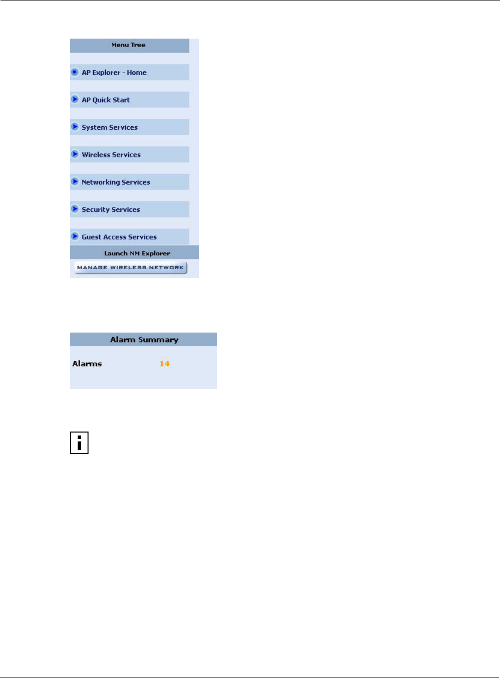
3 Installing the Access Point Using the Configuration Interfaces
40 Installation and User Guide: Airgo Access Point
Figure 23: Menu Tree
The lower left alarm panel (Figure 24) lists the number of current alarms.To update the alarm
summary, click the browser refresh button.
Figure 24: Alarm Area
When you select an item from the menu tree, the information is displayed in the Detail panel, which
takes up most of the browser window (shown for the Home panel in Figure 25).
Getting Help
To access the Online Help system at any time, click the Help button in the upper right area of the
AP Web interface. The Help system opens to provide assistance on the current panel, and includes
links to the table of contents and index.
The Home Panel
The Home panel (Figure 25) opens when you first log in to the web interface, or if Home is
selected from the menu tree. The Home screen contains top-level summary information about the
AP. To access detailed information, click More for any of the following sections:
•AP Summary—Opens the Bootstrap Configuration panel under the AP Quick Start menu (see
“Quick Start Panels” on page 42).
NOTE: Use the Menu Bar rather than the browser Back button to switch to other
panels in the Airgo AP web interface.
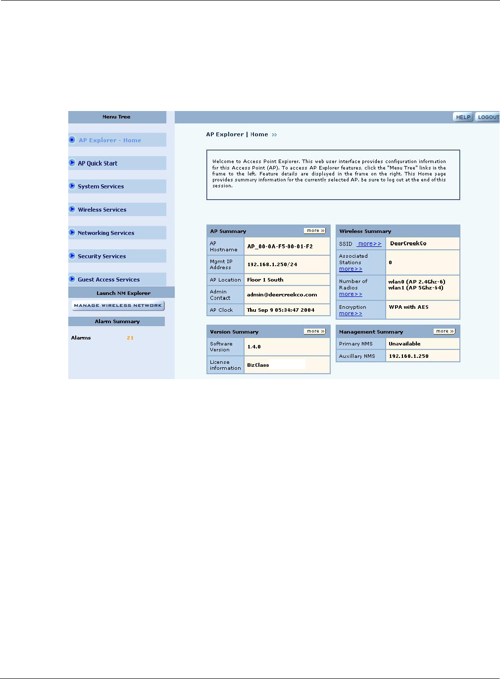
Navigating the Web Interface
Installation and User Guide: Airgo Access Point 41
•Version Summary—Opens a detailed list of model and serial numbers and hardware and
software versions (see “Version Table” on page 47).
•Wireless Summary links—Opens panels to configure SSID, client stations, radios, and
encryption.
•Management Summary—Shows current network management address settings.
Figure 25: Home Panel
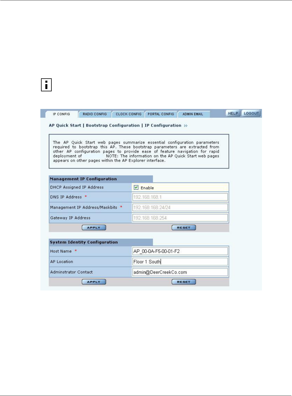
3 Installing the Access Point Using the Configuration Interfaces
42 Installation and User Guide: Airgo Access Point
Quick Start Panels
Use the AP Quick Start menu items to open the Bootstrap Configuration and Version panels. Each
of the tabs in the Bootstrap Configuration panel corresponds to one of the screens used to initialize
an AP in AP Quick Start.
IP Config Tab
The IP Config tab opens when you choose Bootstrap Configuration from the AP Quick Start menu
(Figure 26). Use this tab to configure the management Address of the AP.
Figure 26: AP Quick Start - Bootstrap Configuration - IP Config
This tab contains the following settings:
NOTE: Changing this address will also change the IP address of the management
VLAN on the AP.
Field Description
DHCP Assigned IP
Address
Indicate whether to use DHCP to obtain an IP address for the AP. If the box is
cleared, the other Management IP Configuration fields are activated; if the
box is selected, the other Management IP Configuration fields are inactive.
NOTE: If the web interface is reconfigured with a static IP address, you must
explicitly log back in using the new IP address.
APs.

Navigating the Web Interface
Installation and User Guide: Airgo Access Point 43
Click Apply to save changes in each section on the screen or Reset to return to previously saved
values.
Radio Config Tab
Use the Radio Config tab (Figure 27) to configure bootstrap parameters for the two AP radios.
DNS IP Address Enter the IP address of the server or servers supplying DNS service. This is
required if the IP address is not obtained automatically. The default is the
DNS server for the existing network.
Multiple DNS server addresses may be specified, space-separated. The AP
will use the addresses in the order specified. Manually configured DNS
addresses always take precedence over the DNS addresses returned by a
DHCP server. If the DNS IP Address field is empty, then all manually
configured DNS server addresses will be removed.
If you delete DNS servers, only those added manually are deleted. DHCP-
assigned DNS servers continue to be available.
Management IP
Address/Maskbits
Enter the IP address and subnet prefix for this AP. This is required if the IP
address is not obtained automatically. The default is 192.168.1.254/
24.
Gateway IP Address Enter the IP address of the gateway to the wired network. This is required if
the IP address is not obtained automatically. The default is the existing
network gateway.
Host Name Enter an alphanumeric name for the AP. The factory default for this field is
AP followed by the MAC address of the AP’s Ethernet interface (eth0).
AP Location Enter the physical location of the AP as a text string.
Administrator Contact Enter contact information for the person responsible for managing this AP
(phone or email address).
Field Description
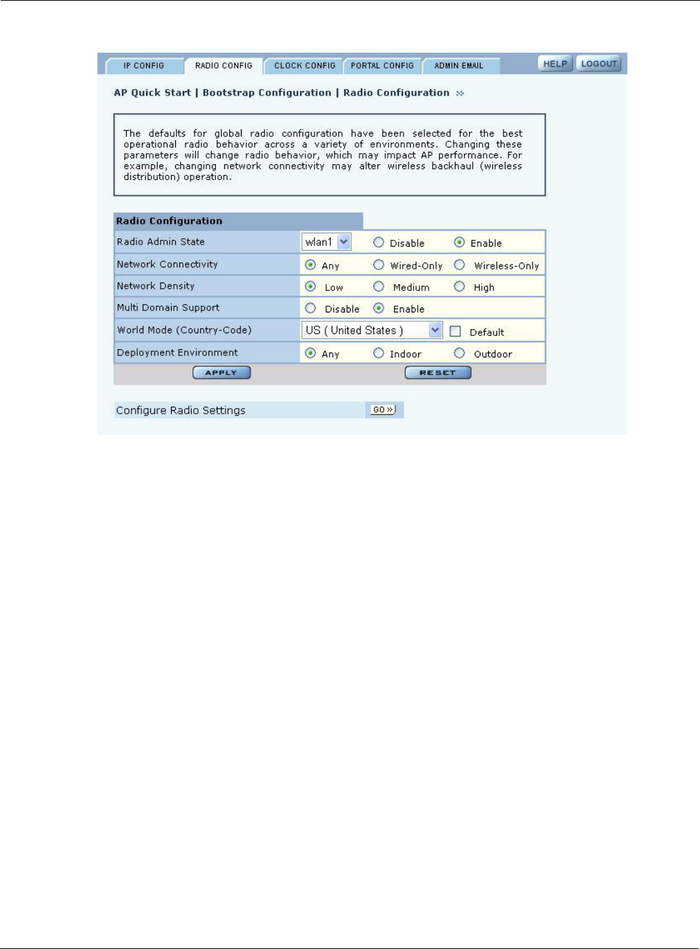
3 Installing the Access Point Using the Configuration Interfaces
44 Installation and User Guide: Airgo Access Point
Figure 27: AP Quick Start - Bootstrap Configuration - Radio Config
This tab contains the following settings:
For further information regarding these settings, see Chapter 4, “Configuring Radio Settings.”
Field Description
Radio Admin State Select each AP radio (wlan0 or wlan1) to enable or disable.
Network Connectivity Indicate whether the radio will be used in a normal AP connected to the wired
network (Wired-Only), for wireless backhaul (Wireless-Only), or may be used
for either (Any). If Any is specified, the system will automatically choose
wired when an Ethernet connection is available and wireless if an Ethernet
connection is not present.
Network Density Indicate the relative concentration of APs in the network. For closely spaced
APs that can support high data rates, select the high density option. For
maximum coverage at lower data rates, select the low density option. The
default setting is Low.
Multi Domain Support Enable or disable 802.11d operation. If Enable is selected, the radio advertises
country, channel, and associated maximum transmit power information in
beacons and probe responses to stations or clients in the BSS. The default
setting is enabled.
World Mode - Country
Code
Select Default to set the channel and power for the radio to the factory default
country setting (U.S.). Alternatively, select a country code from the pull-down
list.
Deployment
Environment
Specify the type of environment in which the AP is installed (indoor, outdoor,
or both). The Environment setting determines the maximum transmit power
and allowed channels of operation. The default is Any.
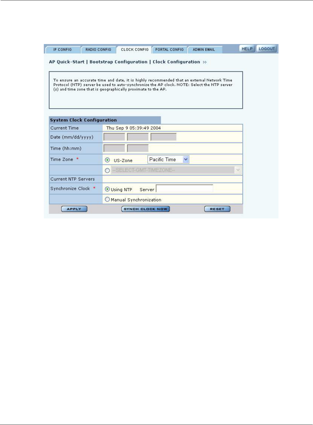
Navigating the Web Interface
Installation and User Guide: Airgo Access Point 45
Clock Config Tab
Use the Clock Config tab (Figure 28) to set time parameters for the bootstrap configuration.
Figure 28: AP Quick Start - Bootstrap Configuration - Clock Config
This tab contains the following settings:
Field Description
Date Current date in MM/DD/YYYY format
Time Current time in HH:MM:SS format (hours 0-23)
Time Zone US-zone or GMT option. For US zone, click the radio button and select a
time zone. For GMT, click the radio button and select an offset in HH:MM
format.
Synchronize Clock Indicate whether time will be synchronized manually through the date and
time fields, or by way of an NTP server. If you select the server option, enter
the IP address of the server in the space provided. If an NTP server is
currently assigned, the address of the server is displayed, as shown in
Figure 28 under the heading Current NTP Servers.
Multiple NTP servers may be specified (space separated). If more than one
server is specified, they are contacted in the order given. If the Synchronize
Clock is empty, then all manually configured NTP servers will be deleted.
If the AP is configured to receive an IP address via DHCP, then the DHCP
server could also return the set of NTP servers. In such a scenario, the
manually configured NTP servers take precedence over the DHCP returned
NTP servers.
If you delete NTP servers, only those added manually are deleted. DHCP-
assigned NTP servers continue to be available.
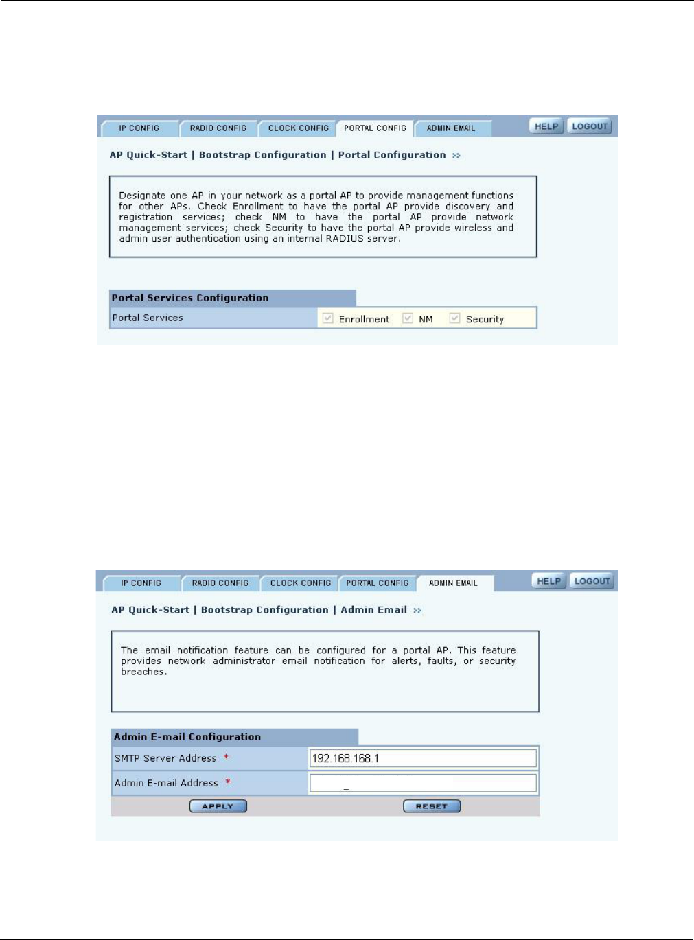
3 Installing the Access Point Using the Configuration Interfaces
46 Installation and User Guide: Airgo Access Point
Portal Config Tab
Use the Portal Config tab (Figure 29) to enable portal services on this AP. See “Portal
Architecture” on page 4 for a description of the portal services.
Figure 29: AP Quick Start - Bootstrap Configuration - Portal Config
Admin Email Tab
If the AP is configured as a portal AP, use the Admin Email tab (Figure 30) to specify how to alert
the network administrator regarding critical faults or security breaches. Configure the following
fields:
Figure 30: AP Quick Start - Bootstrap Configuration - Admin Email
Field Description
SMTP Server Address Enter the IP address of the SMTP server used to reach the network
administrator.
Admin E-mail Address Enter the email address of the network administrator.
rjones@acmeworks.com
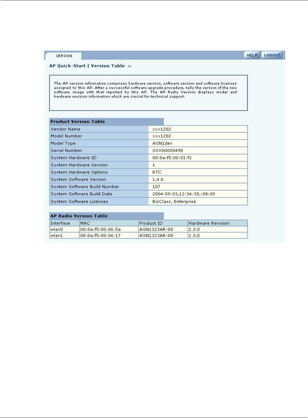
Configuration Wizards
Installation and User Guide: Airgo Access Point 47
Version Table
The Version Table panel (Figure 31) lists model number, serial number, and hardware and software
version information.
Figure 31: AP Quick Start - Version Table
Other Panels
The other panels accessible from the menu tree contain detailed information and fields to set the AP
configuration. Most of the panels have multiple tabs, and some have special entry panels.
NM Portal Access
If the AP is booted in Portal mode, the left side of the browser interface includes a Manage
Wireless Network button just below the menu tree. Click the button to open a new browser window
for NM Portal services. For information on using portal services, see Chapter 9, “Managing the
Network.”
Configuration Wizards
The Airgo AP web interface includes wizards that enable fast configuration of user security and
guest access.
User Security Wizard
The User Security Wizard provides a one-stop interface for configuring user security parameters.
You can use the wizard to configure security or change security settings using the individual
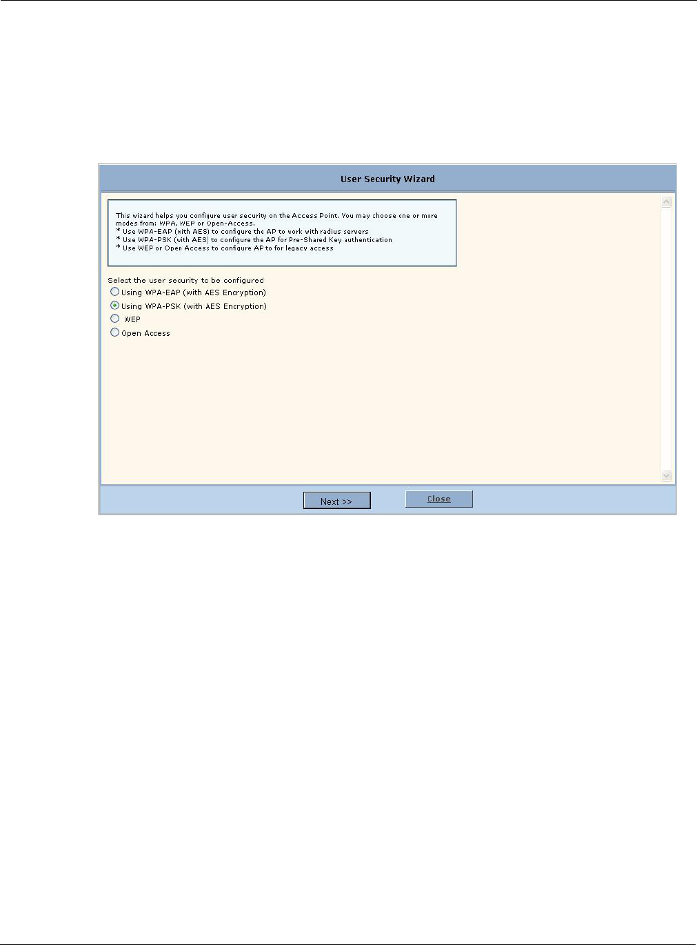
3 Installing the Access Point Using the Configuration Interfaces
48 Installation and User Guide: Airgo Access Point
security panels in the AP web browser interface. For detailed information on security options, see
Chapter 7, “Managing Security.”
To open the User Security Wizard:
Click User Security Wizard under AP Quick Start on the menu tree. The wizard opens
(Figure 32).
Figure 32: User Security Wizard
The wizard presents several options for configuring user security. For additional information about
these options, see Chapter 7, “Managing Security.”
The chosen security option determines the option selections that follow.
To configure WPA-EAP:
1In the User Security Wizard, select Using WPA-EAP.
2Click Next to open the next User Security Wizard panel (Figure 33).
Option Description
WPA-EAP (with AES
encryption)
Configures the AP to work with RADIUS authentication servers.
•The wizard prompts for selection of the internal RADIUS server included
in the AP or an external RADIUS server.
WPA-PSK Configures the AP to work with pre-shared key authentication.
•The wizard prompts for the pre-shared security key.
WEP Configures the AP to use WEP encryption to support legacy equipment.
•The wizard prompts for selection of 64-bit or 128-bit key length option, up
to four distinct WEP keys, and determination of which will be the default.
Open Access Configures the AP with no authentication or encryption.
•The wizard prompts for confirmation that this is desired.
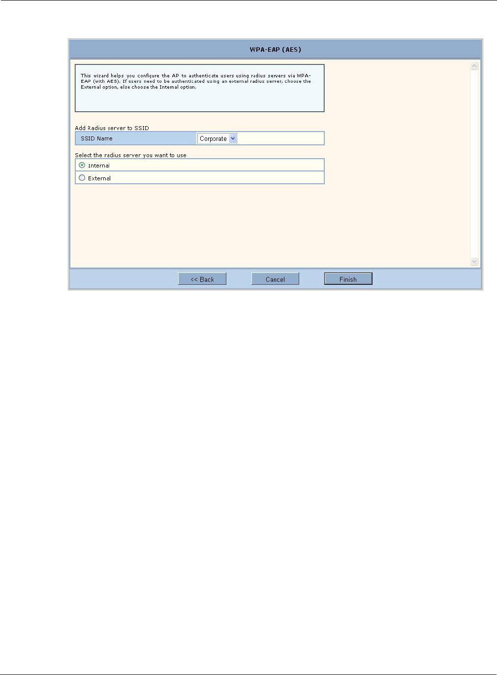
Configuration Wizards
Installation and User Guide: Airgo Access Point 49
Figure 33: User Security Wizard - WPA-EAP
3Confirm the SSID (wireless network name).
4Select whether to use the internal RADIUS server included in the AP or an external RADIUS
server.
5Click Finish.
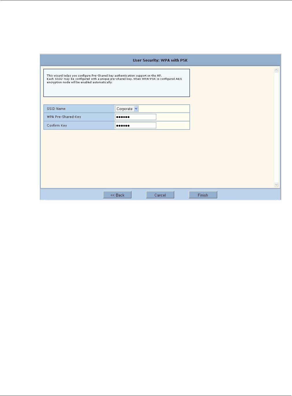
3 Installing the Access Point Using the Configuration Interfaces
50 Installation and User Guide: Airgo Access Point
To configure WPA-PSK:
1In the User Security Wizard, select Using WPA-PSK.
2Click Next to open the next User Security Wizard panel (Figure 34).
Figure 34: User Security Wizard - WPA-PSK
3Enter the pre-shared key to use for network authentication and confirm your entry.
4Click Finish.
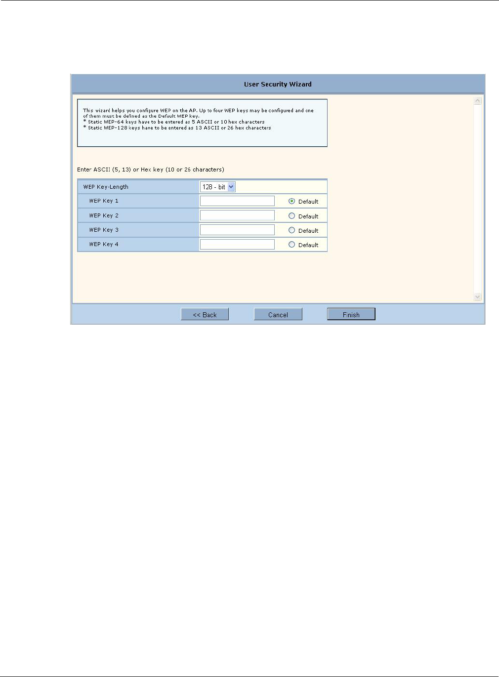
Configuration Wizards
Installation and User Guide: Airgo Access Point 51
To configure WEP:
1Select Using WEP, and click Next to open the next User Security Wizard panel (Figure 35).
Figure 35: User Security Wizard - WEP
2Select the WEP key length.
3Enter up to four WEP keys and indicate which will be the default.
4Click Finish.
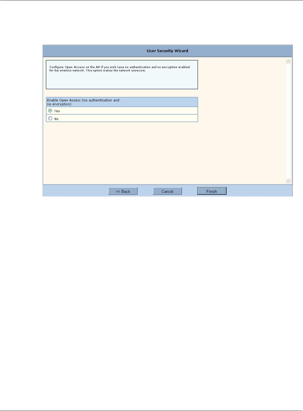
3 Installing the Access Point Using the Configuration Interfaces
52 Installation and User Guide: Airgo Access Point
To configure open access:
1Select Open Access and click Next to open the next User Security Wizard panel (Figure 36).
Figure 36: User Security Wizard - Open Access
2Confirm that you want to configure the AP without user security.
3Click Finish.
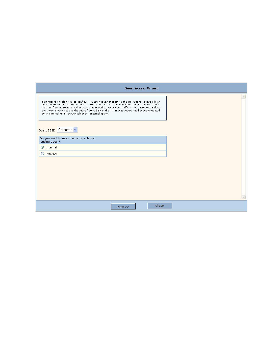
Configuration Wizards
Installation and User Guide: Airgo Access Point 53
Guest Access Wizard
The Guest Access Wizard enables you to configure the network to give guest users limited access
while protecting the network from unauthorized use. For a complete description of guest access
rules and options, see Chapter 8, “Configuring Guest Access.”
To open the Guest Access Wizard:
•Click Guest Access Wizard under AP Quick Start on the menu tree.
The wizard (Figure 37) provides options to configure an internal landing page or an external
landing page for guest users who open a web browser when accessing the network.
Figure 37: Guest Access Wizard
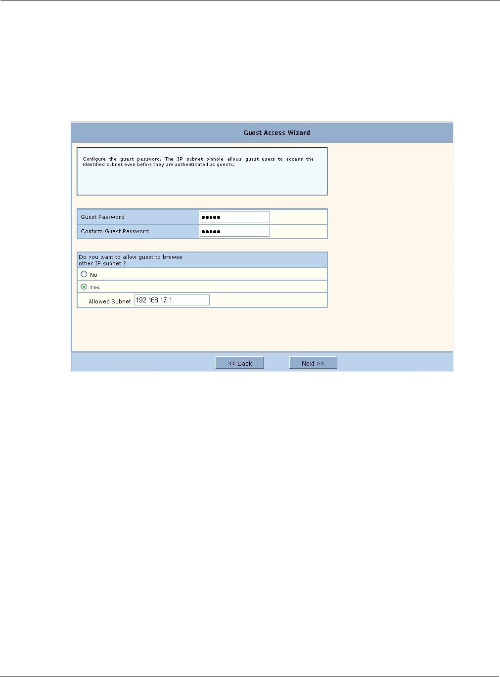
3 Installing the Access Point Using the Configuration Interfaces
54 Installation and User Guide: Airgo Access Point
To use an internal landing page:
1In the Guest Access wizard, select Internal.
2Click Next to open the next wizard panel.
3Enter and confirm a guest password (Figure 38). The password must be from one to 63
characters in length and may be manually distributed to guests who visit your corporate facility.
Figure 38: Guest Access Wizard - Internal Landing Page
4Indicate whether the guest users will be able to access a subnet before they are authenticated as
guest users. If yes, enter the IP address of the subnet.
5Click Next.
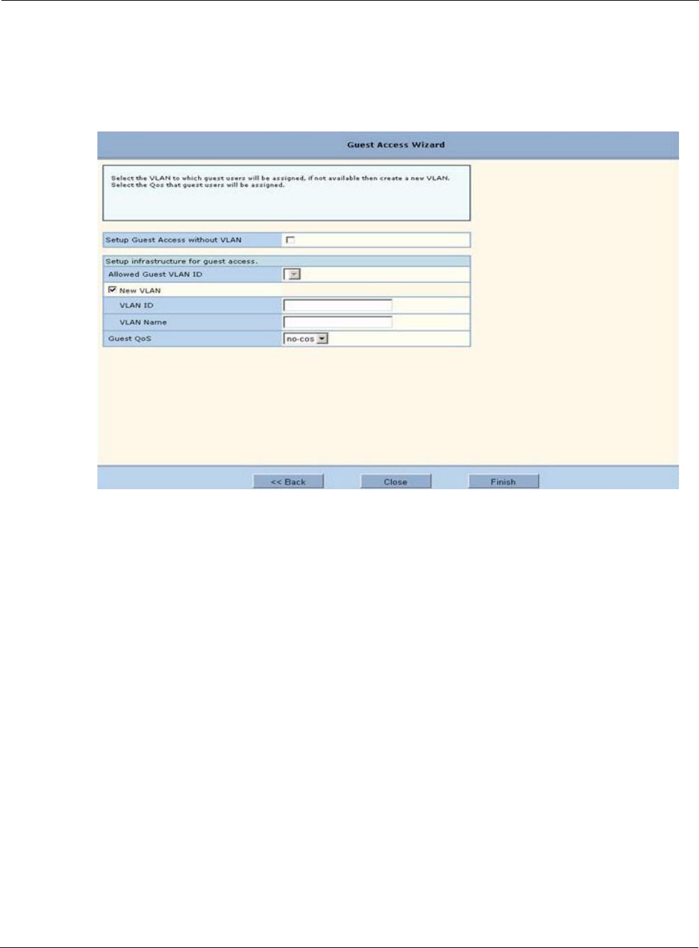
Configuration Wizards
Installation and User Guide: Airgo Access Point 55
6Select the top checkbox if you want to set up guest access without using VLANs. To set up
guest access with VLANs, select an existing VLAN in which to place authenticated guest users
or create a new VLAN by entering a numeric VLAN ID and VLAN name (Figure 39). The list
of existing VLANS includes only those that support open access.
Figure 39: Guest Access Wizard - VLAN Entry
7Click Finish.
Guest access is now configured. When guests access the external landing page, they follow an
externally-determined process to log in to the network. If a subnet has been specified, then guests
can access the subnet even if they are not able to log in. For further information about guest access,
or to modify guest access parameters, see Chapter 8, “Configuring Guest Access.”
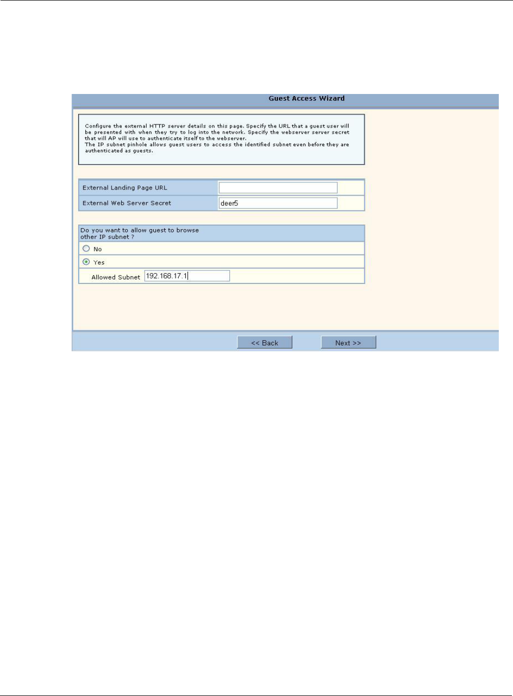
3 Installing the Access Point Using the Configuration Interfaces
56 Installation and User Guide: Airgo Access Point
To use an external landing page:
1In the Guest Access wizard, select External.
2Click Next to open the next wizard panel.
Figure 40: Guest Access Wizard - External Landing Page
3Enter the full URL for the external landing page (Figure 39). The URL for the landing page
must use an IP address rather than a domain name. Regardless of the authentication process
selected for the external page, it is necessary to forward authentication results to the AP upon
completion of successful or unsuccessful guest authentication.
4Enter the shared secret string that the AP will use to authenticate itself to the web server. The
code must be from 1 to 63 characters in length.
5Indicate whether the guest users will be able to access a subnet before they are authenticated as
guest users. If yes, enter the IP address of the subnet.
6Click Next.
7Select the top checkbox if you want to set up guest access without using VLANs. To set up
guest access with VLANs, select an existing VLAN in which to place authenticated guest users
or create a new VLAN by entering a numeric VLAN ID and VLAN name (Figure 39). The list
of existing VLANS includes only those that support open access.
8If desired, select a quality of service (QoS) level. Numeric QoS values range from 0 (lowest
priority) to 7 (highest priority).
9Click Finish.
When guests access the external landing page, they follow an externally-determined process to log
in to the network. If a subnet has been specified, then guests can access the subnet even if they are
not able to log in. For further information about guest access, or to modify guest access parameters,
see Chapter 8, “Configuring Guest Access.”
http://192.168.22.22/Acme_GuestLoginPa

Configuration Wizards
Installation and User Guide: Airgo Access Point 57
NOTE: To successfully authenticate guest users using an external landing page, the
external web server must be configured to accept the guest authentication requests and
to respond with a URL with the correct syntax. For additional information, see
Appendix C, “External Landing Page API.”

3 Installing the Access Point Using the Configuration Interfaces
58 Installation and User Guide: Airgo Access Point

Installation and User Guide: Airgo Access Point 59
4Configuring Radio Settings
This chapter describes the configuration settings for the Airgo Access Point radios and explains
how to set the configuration using the Airgo AP web interface. It covers all the features accessible
from the Wireless Services menu except backhaul configuration, which is discussed in Chapter 6.
The chapter includes the following topics:
•Introduction
•Configuring Radio Parameters
•Setting the Advanced Radio Configuration
•Viewing Radio Statistics
•Viewing Radio Neighbor Details
•Configuring SSID Parameters
•Multiple SSIDs
•Configuring Inter Access Point Protocol (IAPP)
•Performing Radio Diagnostics
Introduction
The Airgo Access Point can be configured with one or two radios, each of which forms a distinct
wireless cell or basic service set (BSS), as shown in Figure 41. Each radio can operate in either of
the following modes:
•In normal mode, the AP is connected to the wired network and the radio directly services
downstream client stations or access points, or both. (AP mode).
•In wireless backhaul mode, the radio establishes a wireless link to a radio in AP mode on
another Airgo AP in order to relay data through the wireless medium. The AP is not attached to
a wired connection; instead it is connected through the wireless medium to another AP.1 In this
mode, the radio is called a Backhaul Point (BP mode). Wireless backhaul is also known as a
wireless distribution system (WDS).
1Except in certain special configurations.

4 Configuring Radio Settings
60 Installation and User Guide: Airgo Access Point
Figure 41: AP Radios and Coverage
Use the Wireless Services items on the menu tree to access wireless parameters. The following
rules apply to the wireless settings:
•Some of the settings apply globally (for both radios); others apply on a per-radio basis.
•For configuration and reference purposes, the individual radios are labeled wlan0 and wlan1.
The wired Ethernet interface is labeled eth0.
•Some of the commands apply only to one mode (AP or BP).
•If the radio is in BP mode, parameters are stored and later applied if and when the radio takes
on the AP mode.
Each of the items in the Wireless Services menu leads to a specific area of radio configuration:
To open one of the Wireless Services panels, choose the topic from the menu tree.
Configuring Radio Parameters
Choose Radio Configuration from the Wireless Services menu to open the AP Radio
Configuration panel. The panel contains the following tabs:
•Global Configuration — Set parameters that apply to both access point radios.
•Persona Configuration — Set the radio mode or persona for normal (AP) operation or wireless
backhaul (BP).
Menu Item Description
Radio Configuration General radio parameters
Advanced Configuration 802.11 mode for each radio
Radio State & Statistics Detailed status and statistics for each radio
Radio Neighbors Identity of neighboring APs within beacon range
SSID Configuration Identification of the SSID parameters and assignment of service profiles
Backhaul Configuration Configuration of wireless backhaul links (See Chapter 6, “Configuring a
Wireless Backhaul.”)
Station Management List of stations associated to the Airgo AP
IAPP Configuration Configuration of Inter-Access Point Protocol for roaming and load balancing
Radio Diagnostics Interface to perform link and walk tests
AP2 CellAP1 Cell
AP1
(Wired AP)
AP2
(Backhaul Point)
Wired Network
A0019A
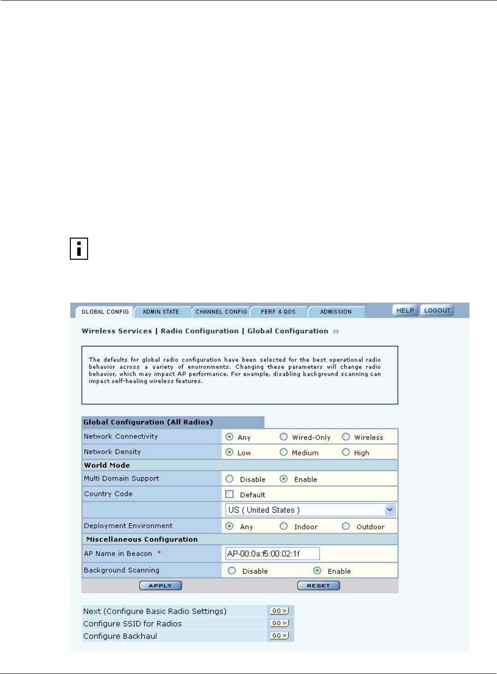
Configuring Radio Parameters
Installation and User Guide: Airgo Access Point 61
•Channel Configuration — Configure channel usage for each radio.
•Performance and QoS — Configure enhanced data rates, performance attributes, and Wi-Fi
Multimedia (WMM) quality of service support.
•Admission — Specify categories of client stations permitted to associate to the selected radio.
To configure settings on these tabs, select each in sequence, or step through using the Go links at
the bottom of the panel (shown in Figure 42).
Many of the radio parameters are interdependent, and the Airgo AP performs consistency checks
during configuration to prevent user actions from adversely affecting radio performance. This is
especially true of dual radio APs, due to the proximity of the two radios. If you attempt to make
configuration changes that are not accepted by the AP, an error message may or may not appear.
Consult the appropriate section in this chapter to determine which parameters are in conflict.
Global Configuration
Use the Global Configuration tab (Figure 42) to define settings that apply to all configured Airgo
AP radios.
Figure 42: Radio Configuration - Global Config
NOTE: All the settings on this tab are optional. If the AP radio is enabled when the
global configuration is changed, then it is necessary to reset the AP for the changes to
take effect. If the radio is disabled, the changes take effect once the radio is enabled.

4 Configuring Radio Settings
62 Installation and User Guide: Airgo Access Point
Set the following global parameters on this tab:
Field Description
Network Connectivity Specify the mode of connectivity to the wired network.
•The default value of Any means that the AP auto-determines whether to
initiate a backhaul based on the presence or absence of an active Ethernet
link. The Any setting is influenced by the number of radios in the Airgo
AP and whether the AP has active Ethernet connectivity. If Any is
selected, the Airgo AP is allowed to change between wireless and wired
mode based on a change in Ethernet status.
•The Wired-Only setting means that the Airgo AP operates only as a wired
node. The node is disabled if the Ethernet link is not active. All radios take
on the AP persona unless explicitly configured as a BP radio.
•The Wireless value means that the AP operates only as a wireless backhaul
node with wireless backhaul connectivity to the wired network. One radio
is automatically assigned the BP persona and one the AP persona. Applies
to dual radio APs only.
The default setting of Any is recommended.
Network Density Set the wireless network density (low, medium, or high). Moving APs closer
to each other increases wireless capacity by providing higher data rates to
clients. To support this configuration, select the high density option. For
maximum coverage at lower data rates, use the low density setting. Each
setting determines the defer threshold parameters for the Airgo AP. The
default is low; the default setting of “low” is appropriate for maximum
coverage.
World Mode - Multi-
Domain Support
Enables or disables 802.11d operation. If Enable is selected, the radio
advertises country, channel, and associated maximum transmit power
information in beacons and probe responses to stations or clients in the BSS.
The default setting is enabled.
NOTE: The World Mode Country Code may be statically assigned to a
particular country due to restrictions prohibiting end-user selection of
frequency and transmit power by some Regulatory Agencies. Refer to the
system specifications for the AP being configured to determine the country in
which this AP is licensed to operate. Currently, the MIC in Japan and the FCC
in the United States require products producing radio waves in the 2.4 and
5GHz bands to adhere to frequency (channel) and transmit power
requirements and prohibit end-user selection of alternative frequencies
(channels) and transmit power.
World Mode - Country
Code
Specify the country of operation of the AP. Select Default to set the channel
and power for the radio to the factory default country setting (U.S.).
Alternatively, enter a country code from the pull-down menu.

Configuring Radio Parameters
Installation and User Guide: Airgo Access Point 63
Click Apply to save changes or Reset to return to previously saved values.
World Mode -
Deployment
Environment
Specify the type of environment in which the AP is installed (indoor, outdoor,
or both). Choosing the environment and country influences the channels of
operation that the AP or BP operate in or use for scanning and the maximum
radio transmit power. If the country or environment is changed, the following
occur:
•The channel selection setting is reset to auto-select channel at startup. To
configure a radio on a specific channel, apply the country configuration
and then specify the channel using the Channel Configuration tab (see
“Channel Configuration” on page 68).
•The channel set configuration is set to system-determined band
configuration.
•All radios in the AP are reset.
For reference, Table 9 provides a list of world modes, including countries,
environments, bands, and valid channels.
AP Name in Beacon Confirm the AP node name advertised in beacons and probe responses. This is
the AP name that clients see when they scan for access points. The default is
the unique ID derived from the Ethernet MAC address of the AP. It is
recommended that you accept the default setting. (required, AP radio only)
Background Scanning Enable or disable background scanning. Background scanning is performed to
collect radio interference and radio neighbor information from the
surrounding RF environment. If auto-select-channel is enabled with the
Periodic option, background scanning should also be enabled. See “Channel
Configuration” on page 68.
Field (continued) Description
Table 9:World Modes
Country Environment Band Valid Channel Numbers
USA, Canada Any 2.4 1,2,3,4,5,6,7,8,9,10,11
USA, Canada Indoor 2.4 1,2,3,4,5,6,7,8,9,10,11
USA, Canada Outdoor 2.4 1,2,3,4,5,6,7,8,9,10,11
USA, Canada Any 5 52,56,60,64,149,153,157,161
USA, Canada Indoor 5 36,40,44,48,52,56,60,64,149,153,157,161
USA, Canada Outdoor 5 52,56,60,64,149,153,157,161
Mexico Any 2.4 1,2,3,4,5,6,7,8,9,10,11
Mexico Indoor 2.4 1,2,3,4,5,6,7,8,9,10,11
Mexico Outdoor 2.4 1,2,3,4,5,6,7,8,9,10,11
Mexico Any 5 149,153,157,161
Mexico Indoor 5 36,40,44,48,52,56,60,64,149,153,157,161
Mexico Outdoor 5 149,153,157,161
Argentina Any 2.4 1,2,3,4,5,6,7,8,9,10,11
Argentina Indoor 2.4 1,2,3,4,5,6,7,8,9,10,11
Argentina Outdoor 2.4 1,2,3,4,5,6,7,8,9,10,11
Argentina Any 5 52,56,60,64,149,153,157,161
Argentina Indoor 5 52,56,60,64,149,153,157,161

4 Configuring Radio Settings
64 Installation and User Guide: Airgo Access Point
Argentina Outdoor 5 52,56,60,64,149,153,157,161
Brazil Any 2.4 1,2,3,4,5,6,7,8,9,10,11
Brazil Indoor 2.4 1,2,3,4,5,6,7,8,9,10,11
Brazil Outdoor 2.4 1,2,3,4,5,6,7,8,9,10,11
Brazil Any 5 149,153,157,161
Brazil Indoor 5 149,153,157,161
Brazil Outdoor 5 149,153,157,161
Countries listed under the heading Europe include major European countries not explicitly listed by name
in this table.
Europe Any 2.4 1,2,3,4,5,6,7,8,9,10,11,12,13
Europe Indoor 2.4 1,2,3,4,5,6,7,8,9,10,11,12,13
Europe Outdoor 2.4 1,2,3,4,5,6,7,8,9,10,11,12,13
Europe Any 5 100,104,108,112,116,120,124,128,132,126,140
Europe Indoor 5 36,40,44,48,52,56,60,64,100,104,108,112,116,120,124,128,13
2, 126,140
Europe Outdoor 5 100,104,108,112,116,120,124,128,132,126,140
France Any 2.4 9
France Indoor 2.4 9
France Outdoor 2.4 9
France Any 5 Not allowed
France Indoor 5 36,40,44,48,52,56,60,64
France Outdoor 5 9,10,11,12,13
Austria Any 2.4 1,2,3,4,5,6,7,8,9,10,11,12,13
Austria Indoor 2.4 1,2,3,4,5,6,7,8,9,10,11,12,13
Austria Outdoor 2.4 1,2,3,4,5,6,7,8,9,10,11,12,13
Austria Any 5 Not allowed
Austria Indoor 5 36,40,44,48,52,56,60,64
Austria Outdoor 5 Not Allowed
Belgium Any 2.4 1,2,3,4,5,6,7,8,9,10,11,12,13
Belgium Indoor 2.4 1,2,3,4,5,6,7,8,9,10,11,12,13
Belgium Outdoor 2.4 1,2,3,4,5,6,7,8,9,10,11,12,13
Belgium Any 5 Not allowed
Belgium Indoor 5 36,40,44,48,52,56,60,64
Belgium Outdoor 5 Not Allowed
Spain Any 2.4 10,11
Spain Indoor 2.4 10,11
Spain Indoor 2.4 10,11
Spain Any 5 100,104,108,112,116,120,124,128,132,126,140
Table 9:World Modes (continued)
Country Environment Band Valid Channel Numbers

Configuring Radio Parameters
Installation and User Guide: Airgo Access Point 65
Spain Indoor 5 36,40,44,48,52,56,60,64,100,104,108,112,116,120,124,128,13
2,126,140
Spain Outdoor 5 100,104,108,112,116,120,124,128,132,126,140
Switzerland Any 2.4 1,2,3,4,5,6,7,8,9,10,11,12,13
Switzerland Indoor 2.4 1,2,3,4,5,6,7,8,9,10,11,12,13
Switzerland Outdoor 2.4 1,2,3,4,5,6,7,8,9,10,11,12,13
Switzerland Any 5 Not allowed
Switzerland Indoor 5 36,40,44,48
Switzerland Outdoor 5 Not Allowed
Japan Any 2.4 1,2,3,4,5,6,7,8,9,10,11,12,13,14
Japan Indoor 2.4 1,2,3,4,5,6,7,8,9,10,11,12,13,14
Japan Outdoor 2.4 1,2,3,4,5,6,7,8,9,10,11,12,13,14
Japan Any 5 34,38,42,46
Japan Indoor 5 34,38,42,46
Japan Outdoor 5 34,38,42,46
Singapore Any 2.4 9,10,11,12,13
Singapore Indoor 2.4 9,10,11,12,13
Singapore Outdoor 2.4 9,10,11,12,13
Singapore Any 5 52,56,60,64,149,153,157,161
Singapore Indoor 5 36,40,44,48,52,56,60,64,149,153,157,161
Singapore Outdoor 5 52,56,60,64,149,153,157,161
Israel Any 2.4 4,5,6,7,8,9
Israel Indoor 2.4 4,5,6,7,8,9
Israel Outdoor 2.4 4,5,6,7,8,9
Israel Any 5 52,56,60,64,149,153,157,161
Israel Indoor 5 36,40,44,48,52,56,60,64,149,153,157,161
Israel Outdoor 5 52,56,60,64,149,153,157,161
Table 9:World Modes (continued)
Country Environment Band Valid Channel Numbers
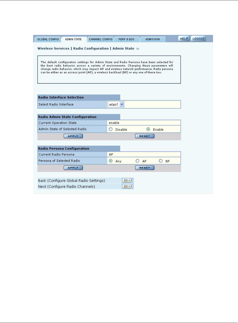
4 Configuring Radio Settings
66 Installation and User Guide: Airgo Access Point
Admin State Configuration
Use the Admin State tab (Figure 43) to assign the mode or persona of each radio interface.
Figure 43: Radio Configuration - Admin State
Set the following parameters on this tab:
Feature Description
Select Radio Interface Select the AP radio (wlan0 or wlan1).
Current Operation State Displays the current operational state of the radio.
Admin State of Selected
Radio
Enable or disable the selected radio. When the AP radio is in the disabled
state, all valid configuration settings are saved. When the AP radio is enabled,
the latest configuration is applied. It is not possible to disable the BP radio by
administrative intervention. Only the AP radio may be disabled.
Current Radio Persona Displays the current mode of operation of the radio.
Persona of Selected
Radio
Select whether the AP radio is to operate as a normal AP (AP) or in backhaul
point mode (BP). Select Any to determine the radio mode automatically based
on network connectivity, configuration, number of radios, and presence of
Ethernet connectivity. It is recommended that you accept the default setting of
Any.

Configuring Radio Parameters
Installation and User Guide: Airgo Access Point 67
Click Apply to save changes or Reset to return to previously saved values.
Admin State Interdependencies
If Network Connectivity on the Radio Global tab (“Global Configuration” on page 61) is set to
Wireless, then at least one radio must have the BP or Any persona. If the Network Connectivity
setting is Wired or Any, then the personas of AP, BP, and Any are all permitted.
Table 10 shows how the Network Connectivity setting on the Global Configuration tab relates to
the Radio Persona Configuration on the Admin state tab.
NOTE: Each access point can have at most one BP radio.
Table 10: Radio Settings for Network Connectivity and Persona
Number of
Radios
Wired
Connectiona
aWired Connection means that the AP has Ethernet connectivity and that the connection is active.
Network
Connectivity
Setting Persona Setting Resulting Radio Persona or Mode
One Yes Any Any or AP AP
One Yes Any BP BP
Two Yes Any All combinations
of Any and AP
Both radios AP
Two Yes Any All combinations
that specify a BP
radio
1 radio AP, 1 radio BP
Two No Any One radio set as
BP
1 radio AP, 1 radio BP
Two No Any Both radios AP Not permitted
One Yes Wired Any AP
Two Yes Wired All combinations
of Any and AP
Both radios AP
Two No Wireless All combinations
except both
radios AP
1 radio AP, 1 radio BP
Two No Wireless Both radios AP Not permitted
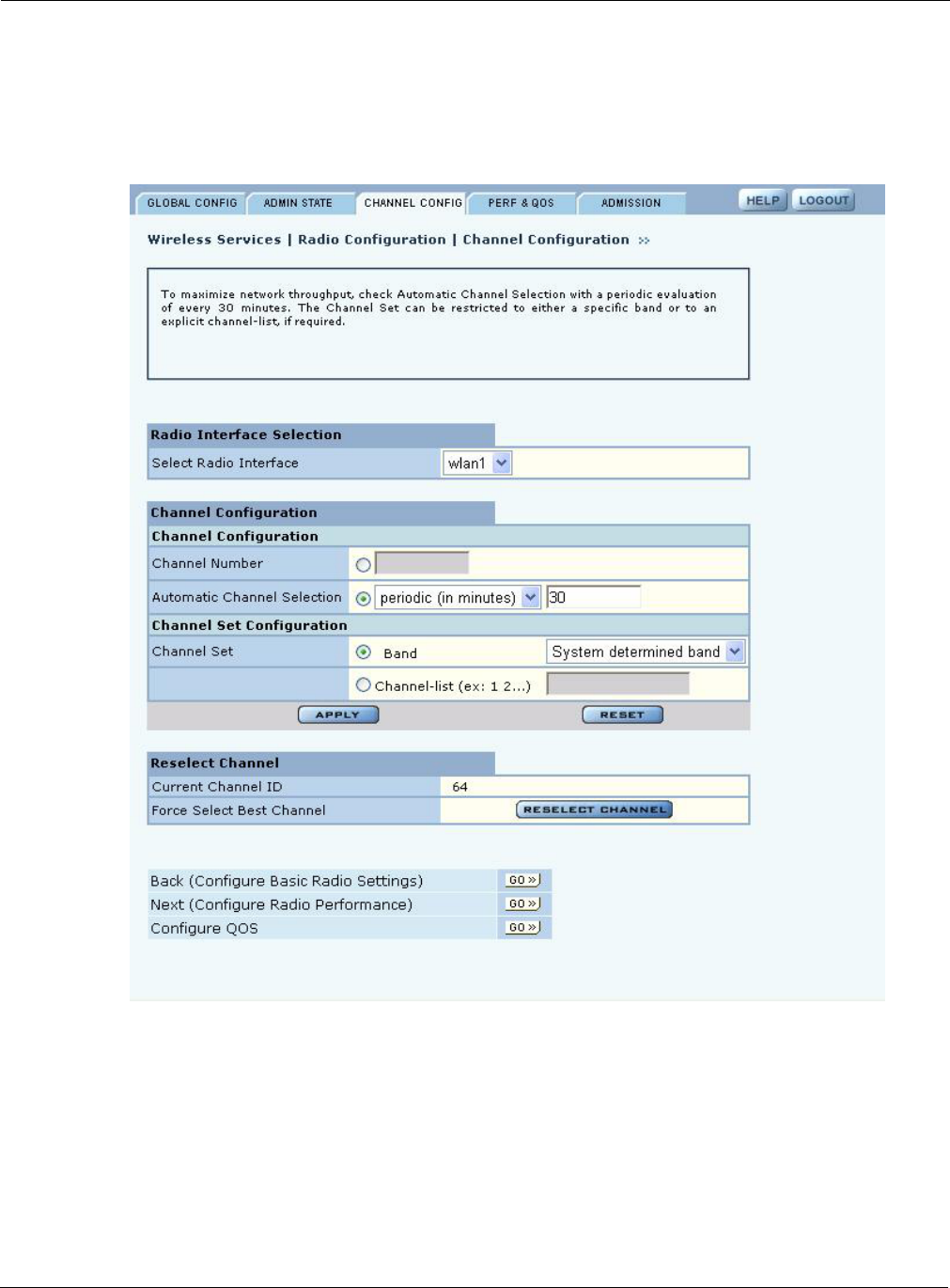
4 Configuring Radio Settings
68 Installation and User Guide: Airgo Access Point
Channel Configuration
Use the Channel Configuration tab (Figure 44) to define rules for selecting radio channels. If two
radios are installed in the same AP, each radio operates in a different band (2.4GHz for one radio
and 5GHz for the other).
Figure 44: Radio Configuration - Channel Config
Set the following values in the Radio Interface Selection and Channel Configuration areas of the
tab:
Feature Description
Select Radio Interface Select the AP radio (wlan0 or wlan1).
Channel Number Select a valid channel for radio operation, or accept the Automatic Channel
Selection option.

Configuring Radio Parameters
Installation and User Guide: Airgo Access Point 69
Click Apply to save changes or Reset to return to previously saved values. Click Reselect Channel
to force the channel selection algorithm for the AP radio to trigger, including a switch-over to a
better channel, if available. The Reselect Channel button applies only to the selected AP radio
interface.
Automatic channel
selection
Specify whether the channel is chosen when the AP is started, or whether it is
selected periodically. The time range for periodic channel selection is 30
minutes to 24 hours (1440 minutes). It is recommended that you accept the
default setting of automatic channel selection of periodic at 30 minutes.
Channel Set Determine which channels the AP scans in order to determine the best channel
for operation. If Auto-Selection is enabled, this determines the channel set for
auto-selection. The following choices are available for channel set:
Band — Select a specific band, or the system-determined band option
(recommended).
•The System determined band setting means that the system chooses the
channel list or band for each radio based on the number of AP radios, the
persona of the radio, and the channel set of any second radio in the AP. If
the radio is in AP mode, the node selects the best channel across both
bands. If the radio is in BP mode, the BP radio scans on both bands.
•If the Airgo AP is configured with two AP radios and Auto-Selection is
chosen for both, the preferred band configuration for both radios is System
determined. If both radios are in AP mode, one operates in the 2.4GHz
band and the other in the 5GHz band.
•If the band is 2.4 or 5GHz, the AP radio operates only in the specified
band. If it is set to 2.4GHz, the AP chooses only non-overlapping channels
for operation (for example 1, 6, and 11). It is not possible to set both radios
to operate in the 2.4GHz or 5GHz band.
•If both bands are selected, the AP radio chooses the best channel based on
the mode and band of the other radio on the AP (if installed).
•If a BP radio establishes a backhaul in the same band as the other AP radio,
this triggers the AP radio to change bands, provided that the AP radio is
configured for auto-selection and the system determined band.
Channel List — Enter a specific list of channels to be scanned, separated by a
single space (e.g.,1 2 6 11 13...). Overlapping channels can be specified in the
2.4GHz band.
NOTE: World mode and environment settings influence the channel and channel set
configurations. See “Global Configuration” on page 61 for information on world
modes.
Feature (continued) Description
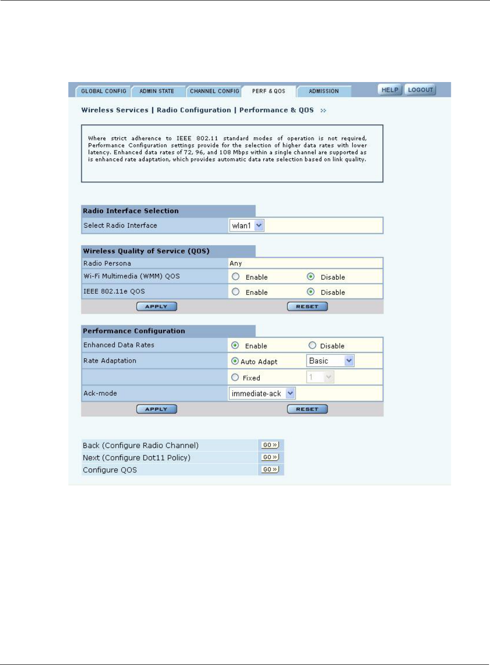
4 Configuring Radio Settings
70 Installation and User Guide: Airgo Access Point
Performance and QoS
Use the Performance and QoS tab (Figure 45) to configure enhanced, True MIMO™ data rates of
72, 96, or 108 Mbps.
Figure 45: Radio Configuration - Performance
Set the following values on this tab:
Feature Description
Select Radio Interface Select the AP radio (wlan0 or wlan1).

Configuring Radio Parameters
Installation and User Guide: Airgo Access Point 71
Click Apply to save changes or Reset to return to previously saved values.
Wireless Quality of
Service (QoS)
Select whether to enable wireless quality of service standards, and click
Apply to save the settings. Click Reset to return to previously saved values.
•Wi-Fi Multimedia (WMM) QoS: Enables or disables the Enhanced
Distributed Channel Access (EDCA) mechanism in the MAC layer. If
enabled, the MAC mode is set to EDCA and signaling between the AP and
client station follow the procedures specified in the WMM specification. If
disabled the MAC mode is set to DCF. Default is Enable.
•IEEE 802.11e QoS: Enables or disables the Enhanced Distributed Channel
Access (EDCA) mechanism in the MAC layer. If enabled, the MAC mode
is set to EDCA and signaling between the AP and client station follow the
procedures specified in the 802.11e specification. If disabled, then the
MAC mode is DCF. Default is Enable. 802.11e QoS works only if the AP
and client station both support True MIMO™.
Performance
Configuration
Configure the following parameters, and then click Apply to save the values.
Click Reset to return to previously saved values.
•Enhanced Data Rates: Enable or disable the True MIMO™ enhanced data
rates (72, 96, and 108 Mbps). This setting is rejected if the enhanced Dot11
extensions are disabled and an attempt is made to configure enhanced data
rates. It is recommended that you accept the default of Enable.
•Rate Adaptation: Enables or disables automatic data rate adaptation in the
system. To use auto-adaptation, select the Auto Adapt button and select the
Basic or Advanced option. Otherwise, select fixed, along with a fixed rate.
It is recommended that you accept the default value of Auto Adapt and
Basic.
•Ack Mode: Determines the acknowledgement policy for data packets. The
following selections are available:
• immediate-ack: Acknowledgement sent for every packet received
(default)
• burst-ack: Proprietary acknowledgement mode that increases peak
throughput in environments where Airgo True MIMO data rates are
reliably sustained
• auto-ack-policy: No acknowledgement sent when data packets are
received
- To enable high performance, use this setting together with one of
the enhanced data rates.
- If this setting is used, auto-adaptation cannot be enabled for the
selected radio. Only the fixed rate setting applies.
- This mode setting can be used for operations with Airgo clients.
Feature (continued) Description

4 Configuring Radio Settings
72 Installation and User Guide: Airgo Access Point
Interdependencies
The following restrictions apply to combinations of settings on the Channel Configuration and
Performance and QoS tabs:
Item Condition
Fixed data rate
configurations
•If the configured channel is in the 5GHz band or the Channel Set
Band/List is 5GHz, System Determined, or Both, then at least one of
the fixed rates must be other than an 11b rate (1,2,5.5,or 11).
•If the configured channel is in the 2.4GHz band or the Channel Set
Band/List is 2.4GHz only, then only 11b/g rates are accepted.
Assigning an enhanced rate (72, 96, and 108 Mbps) requires that the
enhanced rates option be enabled.
Dot11 QoS settings To enable the Dot11 QoS settings on the Performance tab, you must
enable the standard Dot-11 extensions on the 802.11 Policy tab (see
“802.11 Policy” on page 74).
Wireless Quality of
Service
•When both Wi-Fi Multimedia (WMM) QoS and IEEE 802.11e QoS
are enabled, EDCA is enabled at the access point. Capability
negotiations can be performed by WMM capable stations and also by
802.11e stations with the access point, and WMM and 802.11e IEs are
advertised in beacons and probe responses.
•When WMM is enabled and 802.11e is disabled, EDCA is enabled at
the access point. Capability negotiation with the access point can be
performed only by WMM capable stations, as only WMM IEs are
advertised in beacons and probe responses.
•When WMM is disabled and 802.11e is enabled, EDCA is enabled at
the access point. Capability negotiation with the access point can be
performed only by 802.11e capable stations, as only 802.11e IEs are
advertised in beacons and probe responses.
•When both WMM and 802.11e are disabled, DCF mode is enabled at
the access point. Neither the WMM or 802.11e is advertised in
beacons and probe responses.
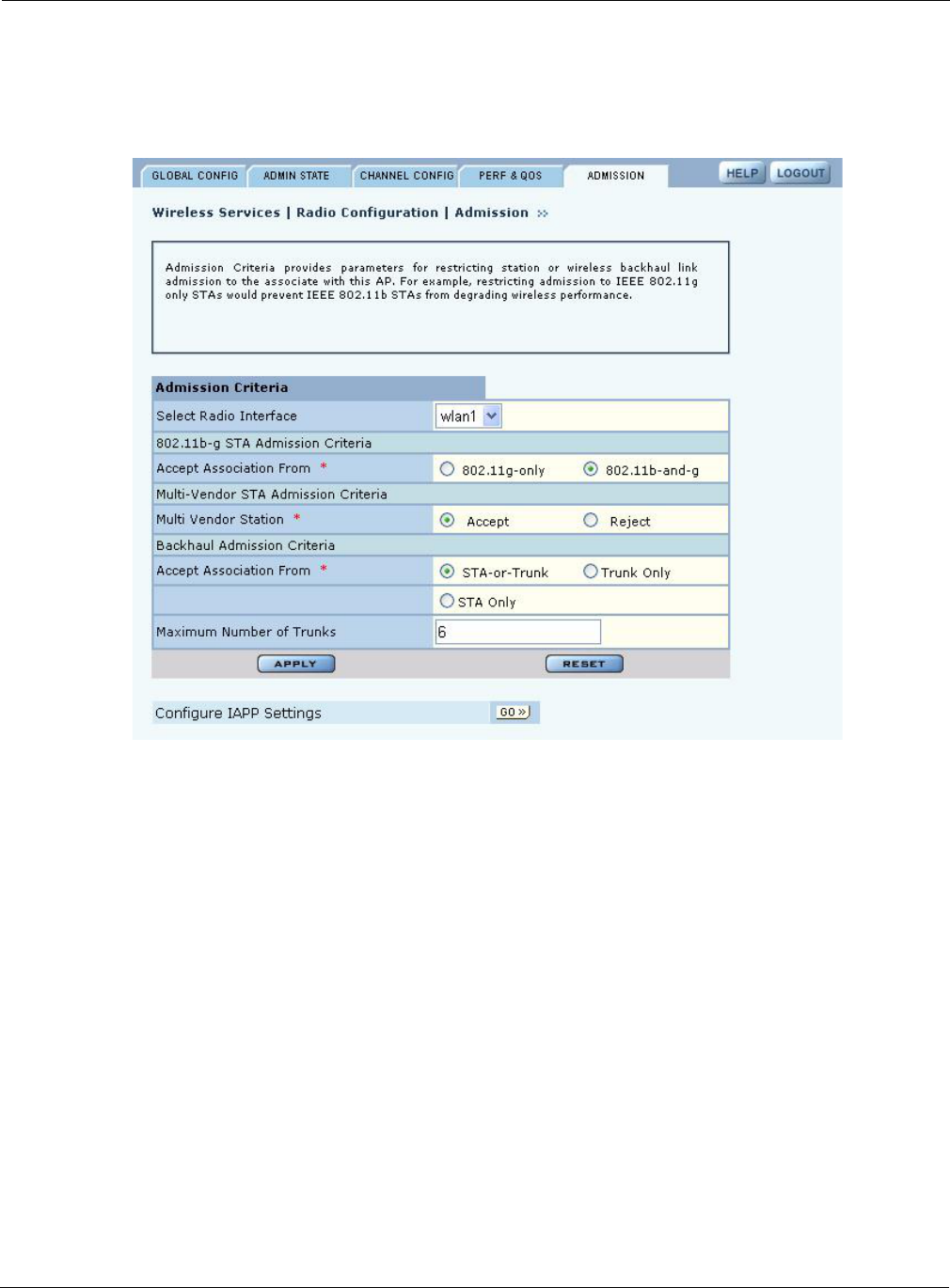
Configuring Radio Parameters
Installation and User Guide: Airgo Access Point 73
Admission
Use the Admission tab (Figure 46) to specify categories of client stations permitted to associate to
the selected radio.
Figure 46: Radio Configuration - Admission
Set the following values on this tab:
Feature Description
Select Radio Interface Select the AP radio (wlan0 or wlan1).
802.11b-g STA
Admission Criteria -
Accept Association
from
Applies to the 2.4GHz band only. Specify the type of 802.11g-or 802.11b and
g client stations permitted to associate. Selecting 802.11g-only keeps 802.11b
stations from degrading BSS performance. 802.11b- and g- is the default
setting.
Multi-Vendor STA
Admission Criteria -
Multi-Vendor Station
Accept allows all stations to associate; Reject restricts association to
compatible client stations, excluding non-compatible or non-Airgo Networks
stations.
Backhaul Admission
Criteria - Accept
Association From
Indicates whether to accept association from client stations, trunks, or both:
STA-or-Trunk — Accept association from client stations or BP radios.
Trunk Only — Accept associations only from BP radios.
STA Only — Accept associations only from client stations.
Max Number of Trunks Determines the maximum number of trunks allowed to form with the AP radio
(range is 1-10). Default is 6.
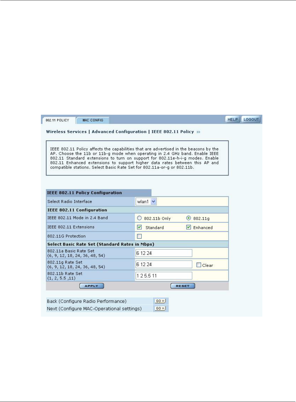
4 Configuring Radio Settings
74 Installation and User Guide: Airgo Access Point
Setting the Advanced Radio Configuration
Select Advanced Configuration from the Wireless Services menu to open the Advanced
Configuration feature panel. The panel contains the following tabs:
•802.11 Policy — Set the 802.11 modes for the AP radios.
•MAC Configuration —Set details of the radio beacon and MAC configuration for each radio.
To configure settings on these tabs, select each in sequence, or step through the tabs using the Go
links at the bottom of the panel.
802.11 Policy
Use the 802.11 tab (Figure 47) to set the 802.11 modes and data rates for each AP radio.
Figure 47: Advanced Configuration - 802.11 Policy
Set the following values on this panel:
Feature Description
Select Radio Interface Select the AP radio (wlan0 or wlan1).
IEEE 802.11 Mode in
2.4 Band
Select whether the radio is configured for 802.11b or 802.11g operation when
it operates in the 2.4GHz band.

Setting the Advanced Radio Configuration
Installation and User Guide: Airgo Access Point 75
Click Apply to save changes or Reset to return to previously saved values.
IEEE 802.11 Extensions Enable 802.11 Standard Extensions to turn on support for 802.11e-h-i-g
modes. Select 802.11 Enhanced Extensions to support higher data rates
between the AP and compatible stations. If the Enhanced option is selected,
then it is possible to enable the following through the command line interface
(they are not automatically enabled).
•Enhanced rate set (specific flag needs to be set).
•Proprietary burst ack. This is a proprietary acknowledgement mode that
increases peak throughput in environments where Airgo True MIMO data
rates are reliably sustained.
•Advanced rate adaptation.
•Wireless backhaul AP name in beacon (if not enabled, the AP name in
beacon is suppressed).
802.11G Protection Select to enable 802.11g protection mode, short slot time, and short preamble
if the radio is operating in 802.11g mode.
If the checkbox is selected, all three aspects are enabled; if not, all three
aspects are disabled. The default setting is Disabled.
Select Basic Rate Set Enter basic data rates for the different 802.11 modes. To set rates, select Set
and enter the rates with a space as the delimiter. The basic 802.11 rates are
advertised in beacons and inform the client stations of the minimum set of
rates it must support to be part of the BSS. 802.11 control frames such as
ACKS, CTS, and RTS are transmitted at basic rates.
Feature (continued) Description
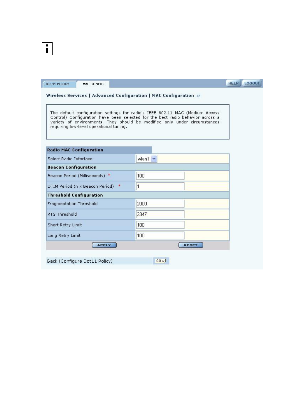
4 Configuring Radio Settings
76 Installation and User Guide: Airgo Access Point
MAC Configuration
Use the MAC Configuration tab (Figure 48) under special circumstances if it is necessary to tune
low level operational parameters of the radio Medium Access Control (MAC) layer.
Figure 48: MAC Configuration Tab
NOTE: Changes on the MAC Configuration tab should only be made by trained
network personnel. The AP radio restarts automatically when these parameter changes
are applied.

Viewing Radio Statistics
Installation and User Guide: Airgo Access Point 77
Set the following parameters on the MAC Configuration tab:
Click Apply to save changes or Reset to return to previously saved values. The changes take effect
immediately if the radio is enabled.
Viewing Radio Statistics
Select Radio State & Statistics from the Wireless Services menu to view the current state of each
radio and the current communication statistics. This panel contains the following tabs:
•Radio State — View current configuration.
•Radio Statistics — View information about current transmission activity.
Radio State
The Radio State tab (Figure 49) contains details on the current configuration and utilization of each
radio interface. The state information varies according to whether the radio is operating as a normal
access point radio (AP mode) or as a backhaul point (BP mode).
Field Description
Select Radio Interface Select the AP radio (wlan0 or wlan1).
Beacon Period Enter the desired interval between RF beacons in milliseconds. It is
recommended that you accept the default of 100 ms. (required).
DTIM (delivery traffic
indication message)
Period
Enter the frequency, in beacon periods, at which the radio forwards multicast
and broadcast packets to client stations. It is recommended that you accept the
default of 1 beacon period. (required).
Fragmentation
Threshold
Enter the maximum packet size that can be transmitted as a single unit. A low
setting may be desirable in areas that have significant interference or poor
signal conditions. The range is 256-2346. It is recommended that you accept
the default of 2000.
RTS Threshold Enter a packet size greater than which the AP issues a request-to-send (RTS)
message before sending the packet. Enter a low threshold if the ambient
conditions might make it relatively difficult for clients to associate to the AP.
The range is 0-2347. It is recommended that you accept the default of 2347.
Short Retry Limit Enter a number of transmission retries (greater than or equal to data frame
MSDU size) after which a transmission is deemed a failure. The range is
0-255.
Long Retry Limit Enter a number of transmission retries (greater than or equal to data frame
MSDU size) after which a transmission is deemed a failure. The range is
0-255.