Airspan Communications 495AS Airsynergy Compact Outdoor Pico Base Station User Manual Installation Guide
Airspan Communications Limited Airsynergy Compact Outdoor Pico Base Station Installation Guide
Contents
- 1. Installation Guide
- 2. Additional User Manual Statement
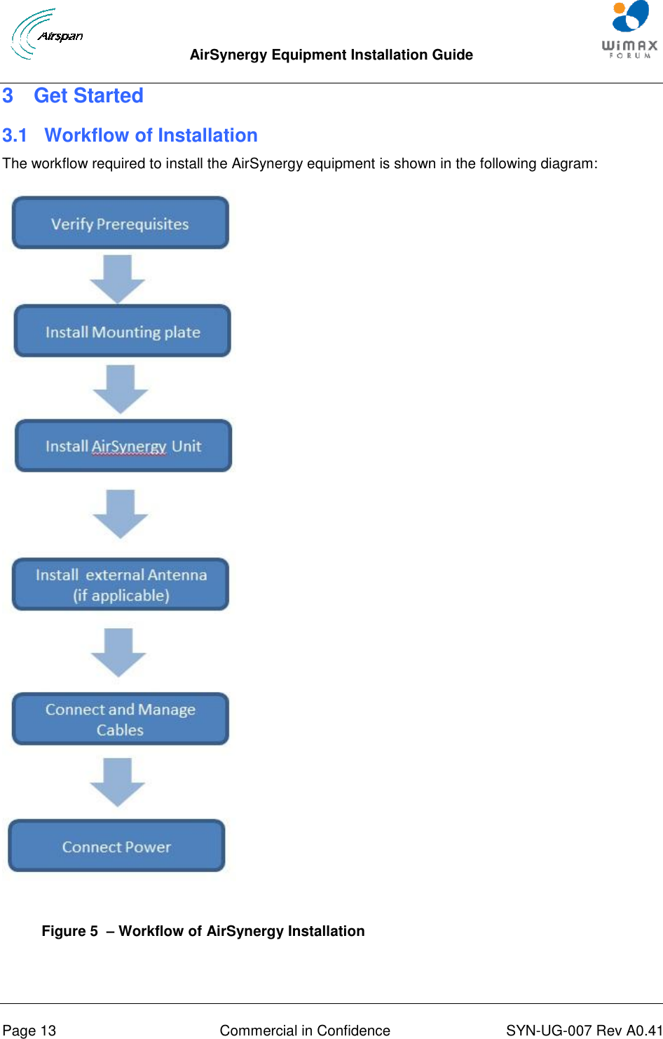
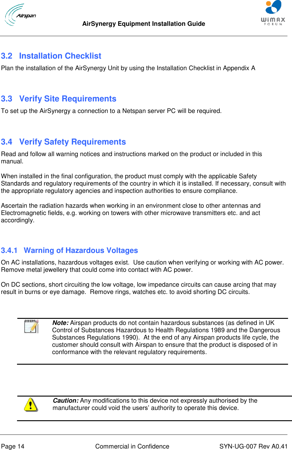
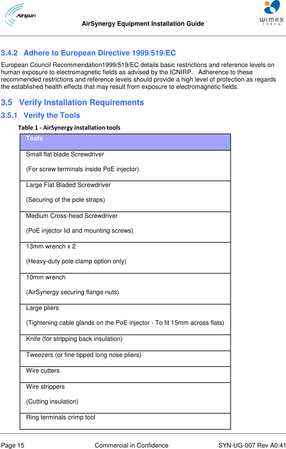
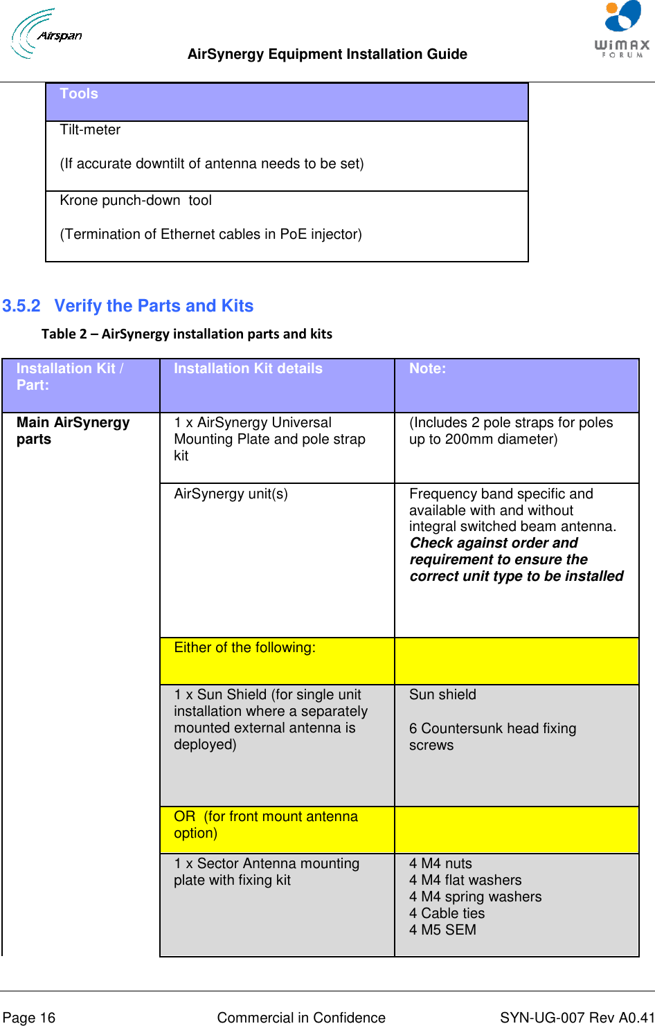
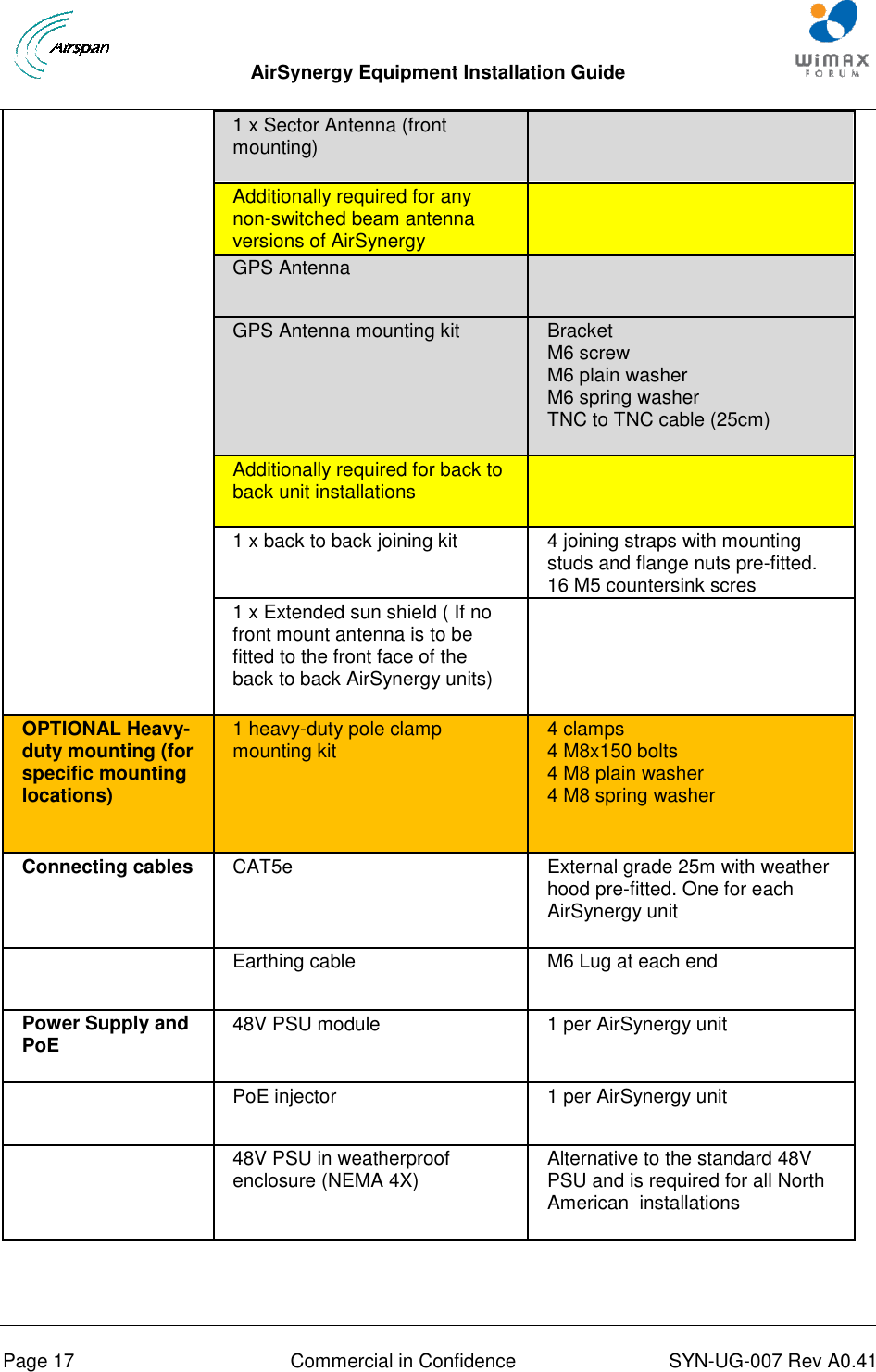
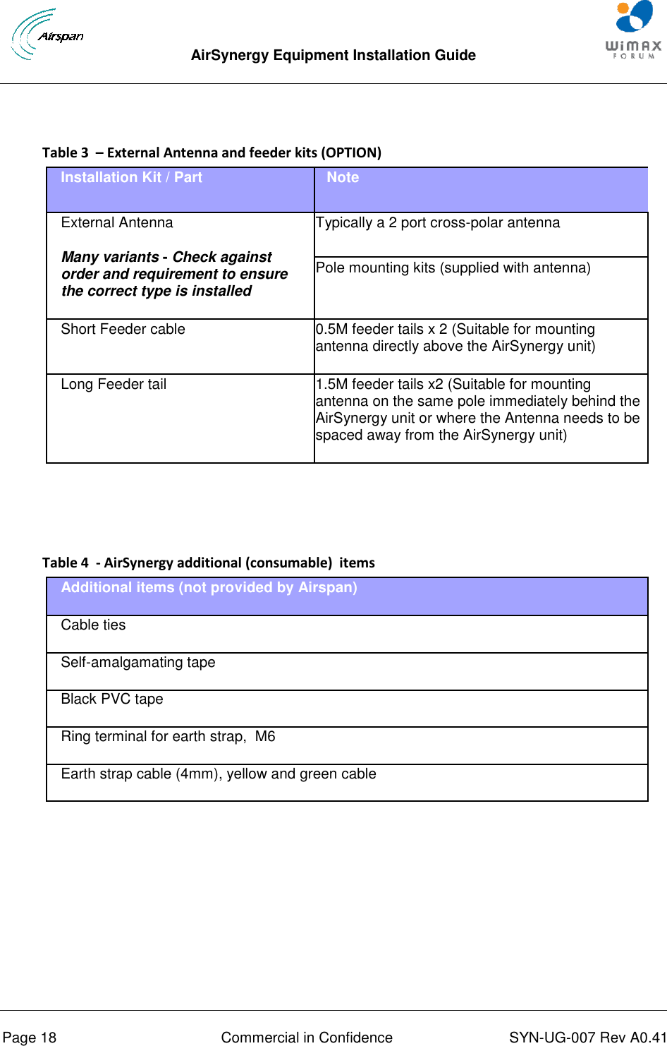
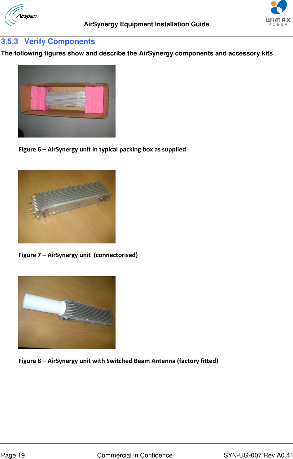
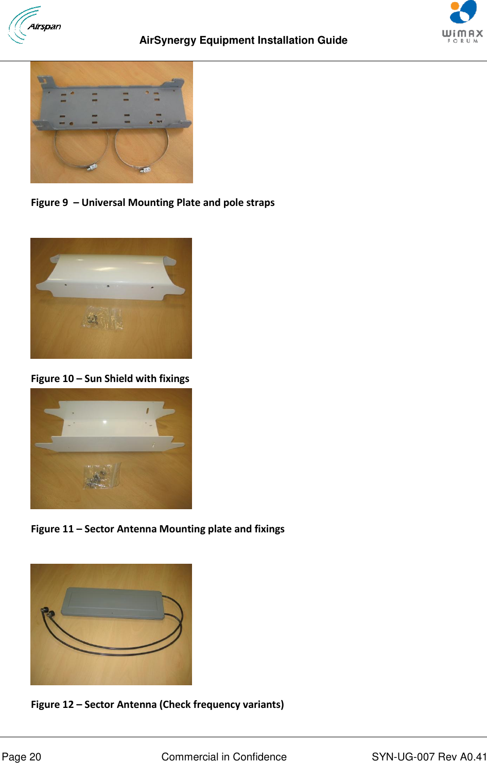
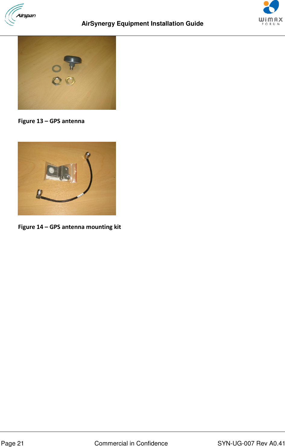
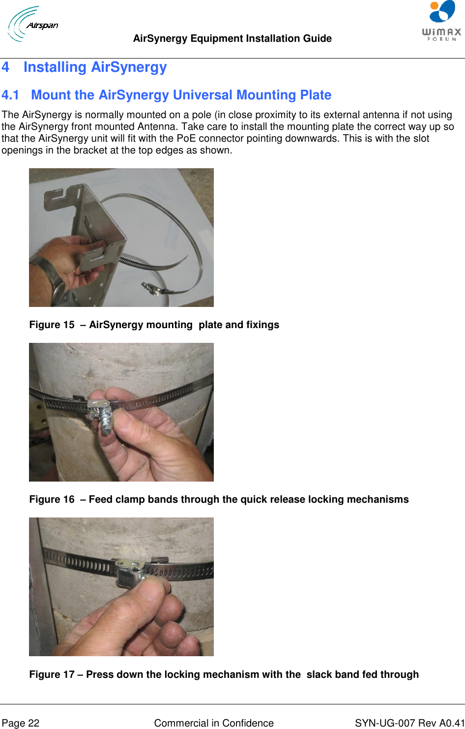
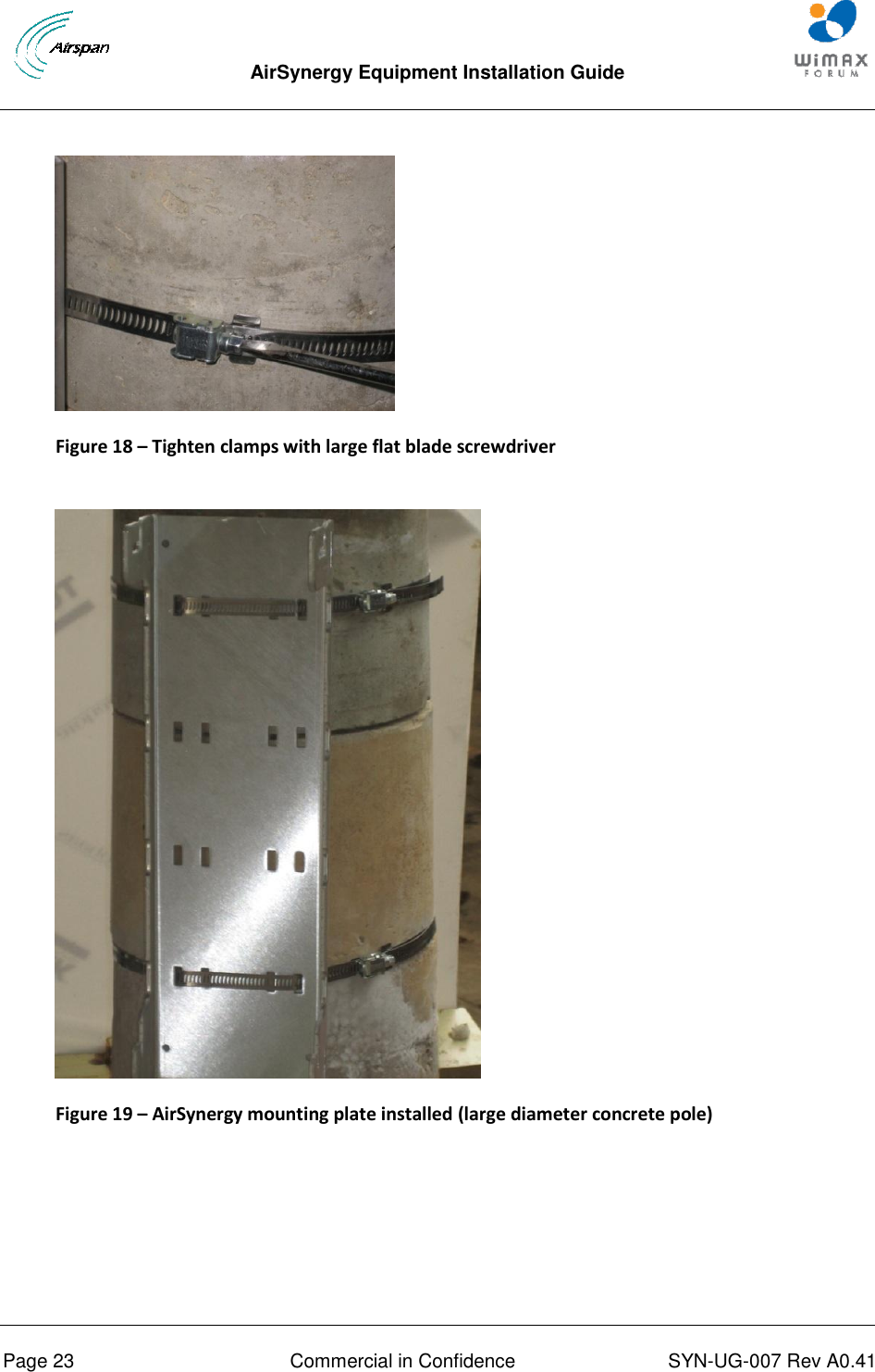
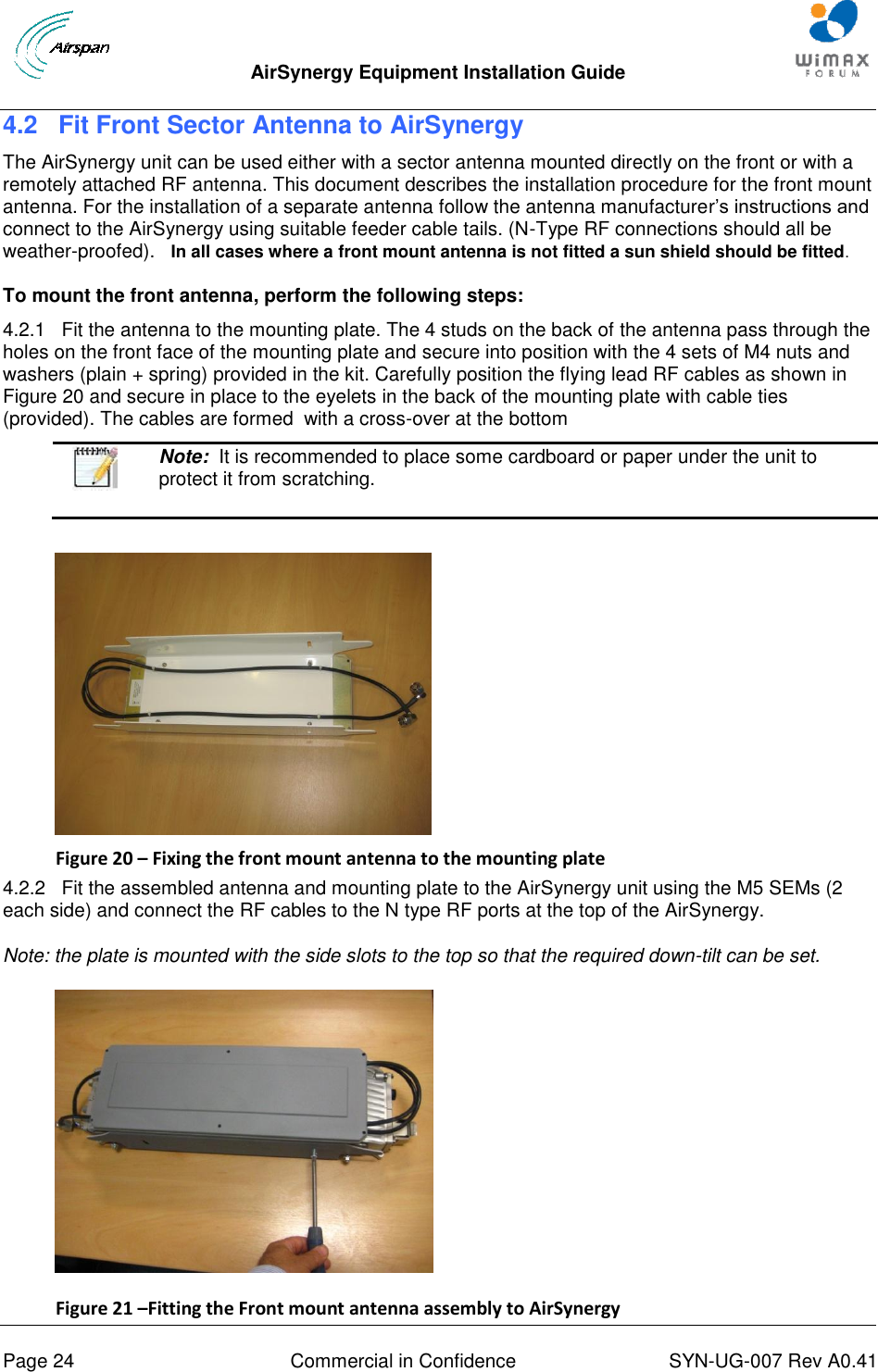
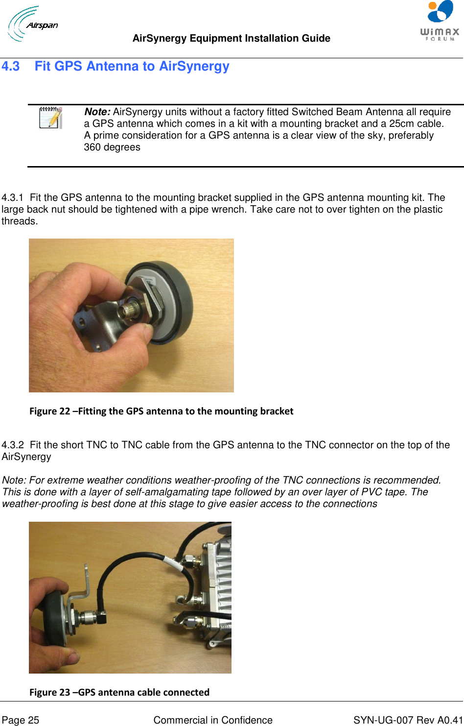
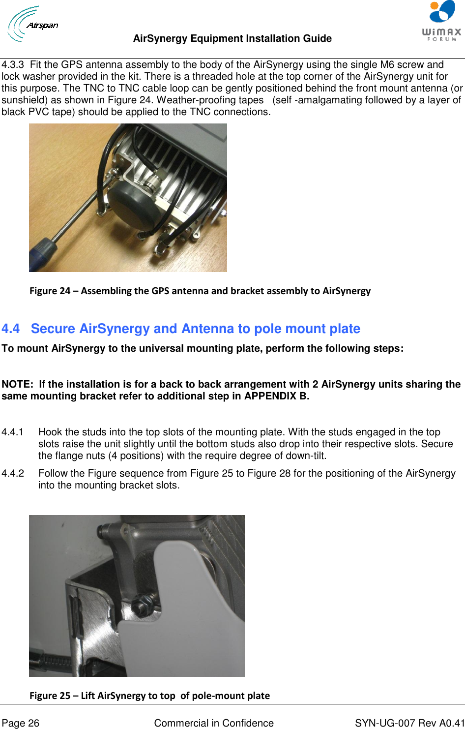
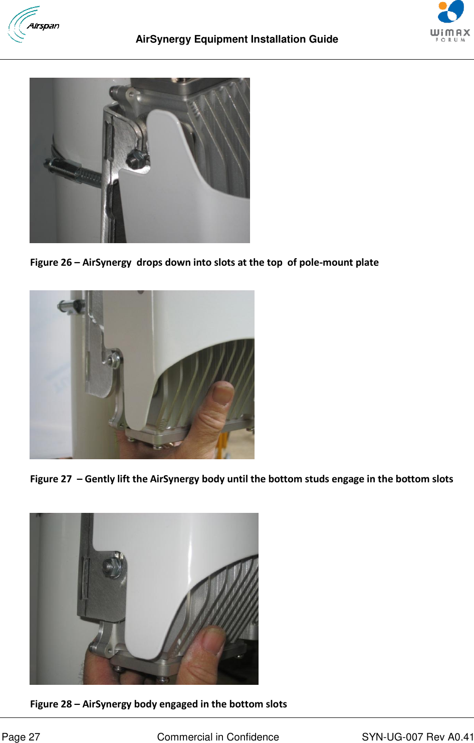
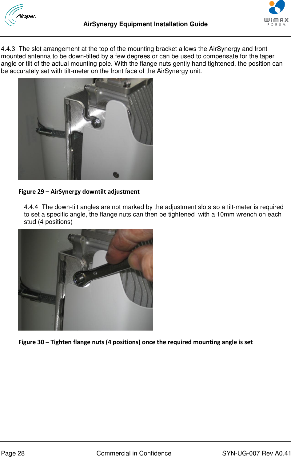
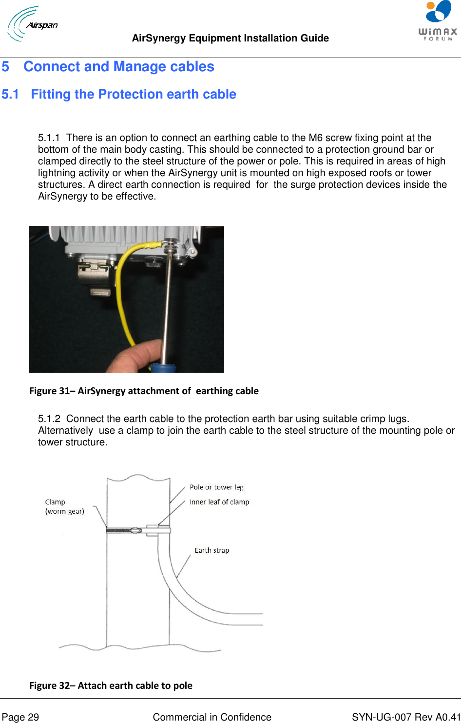
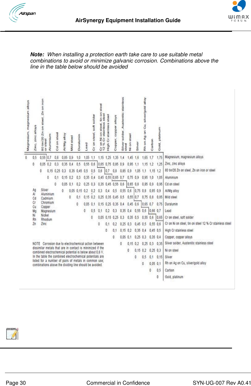
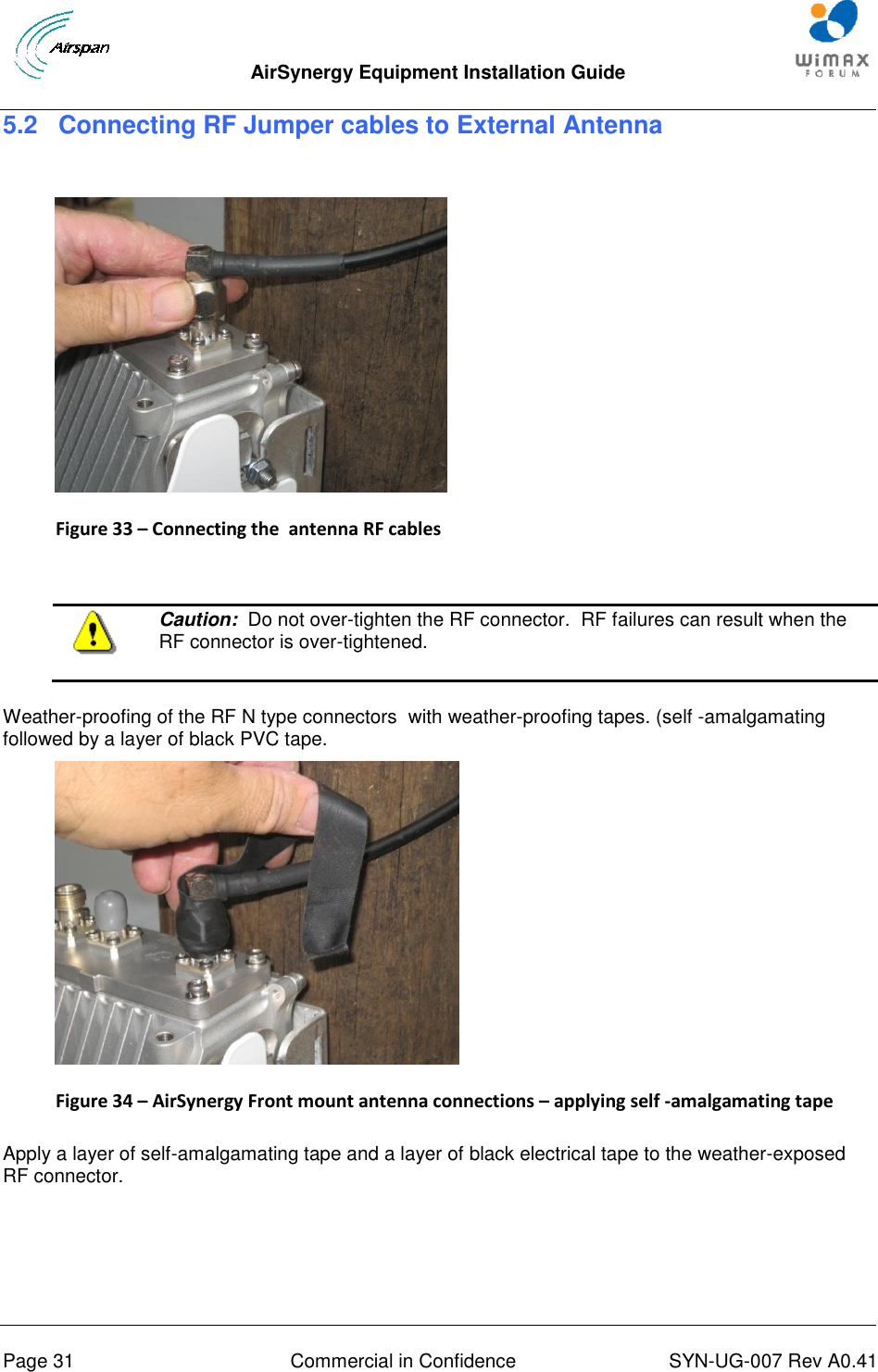
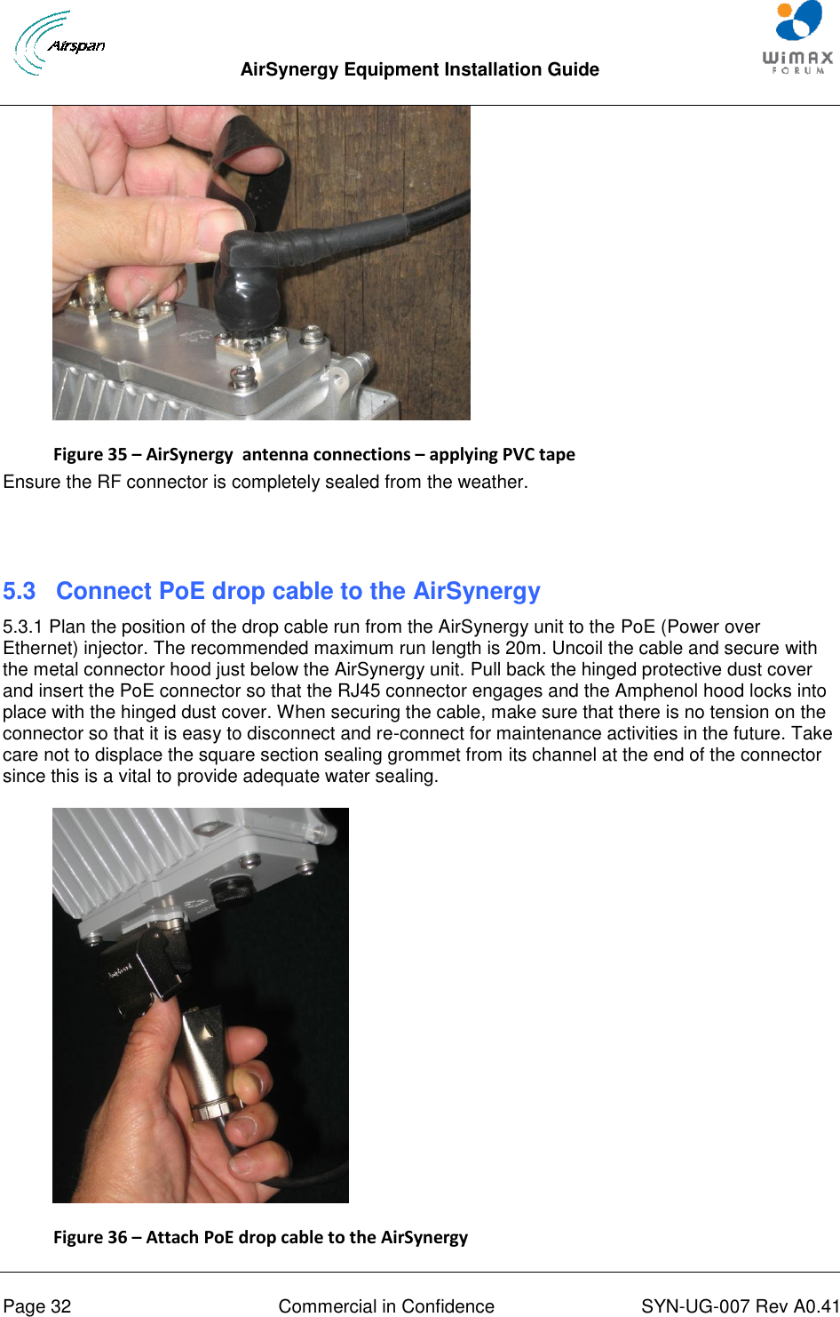
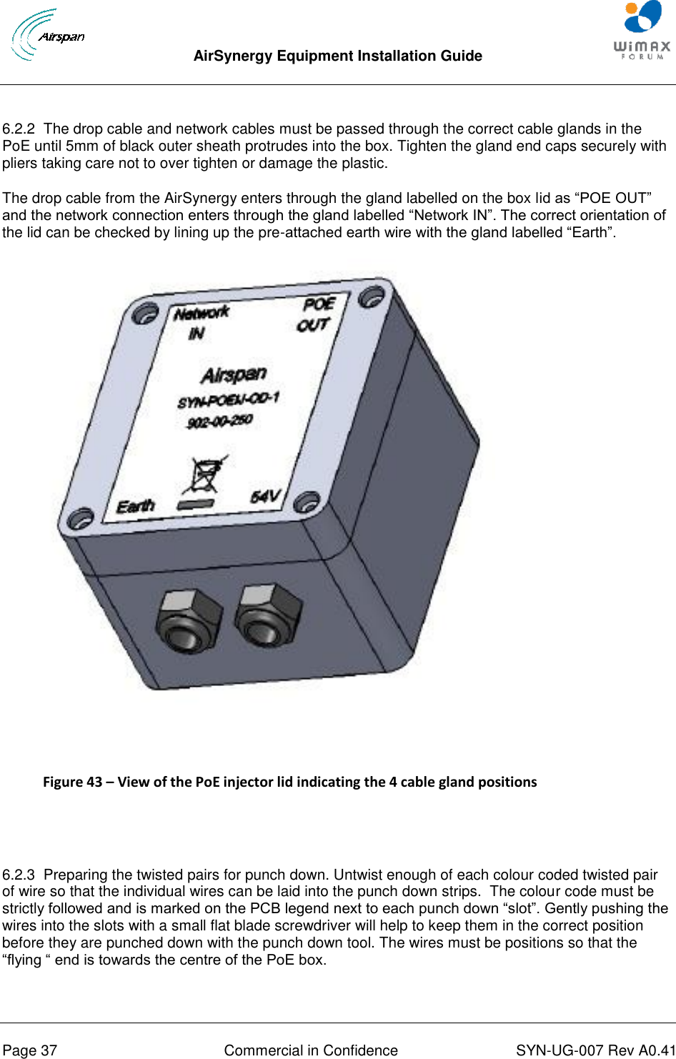
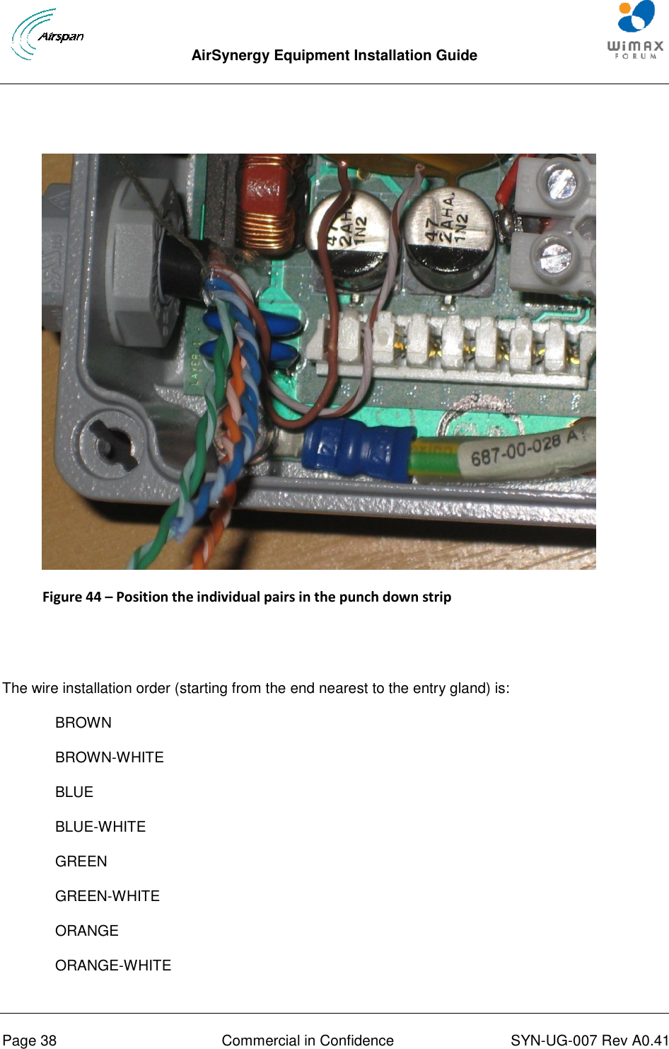
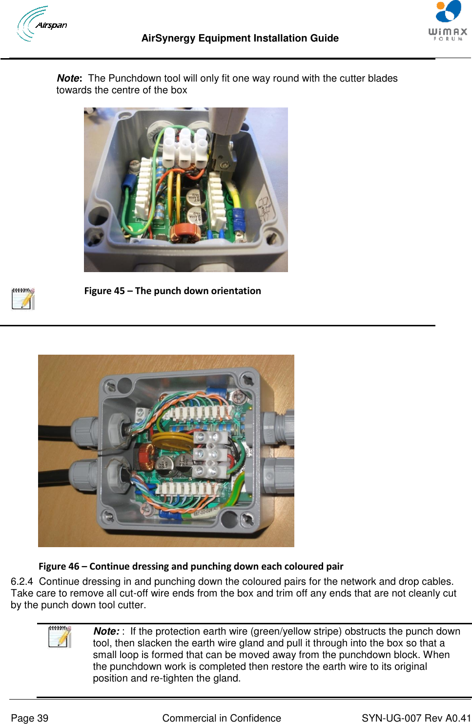
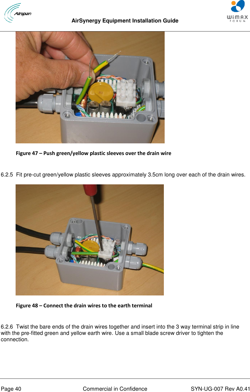
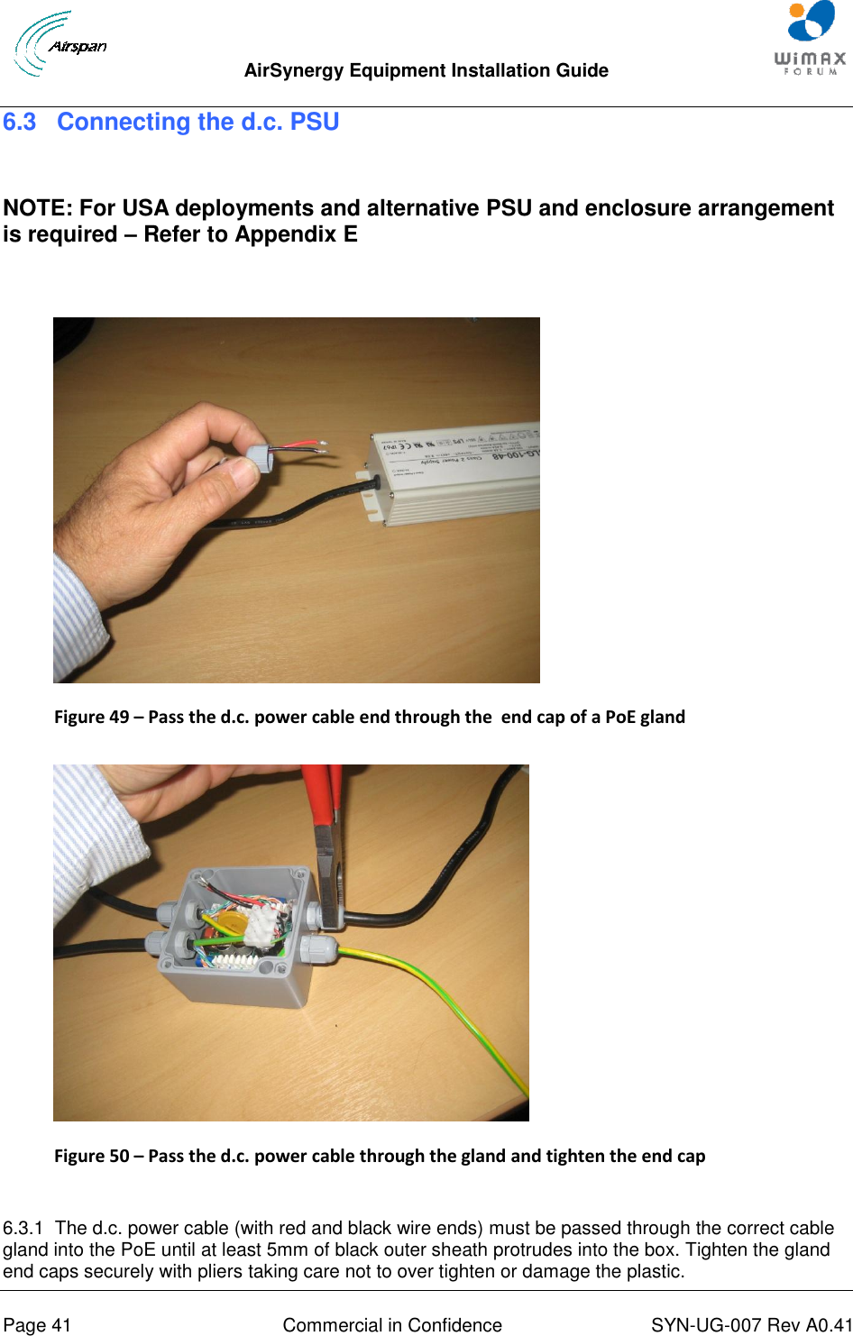
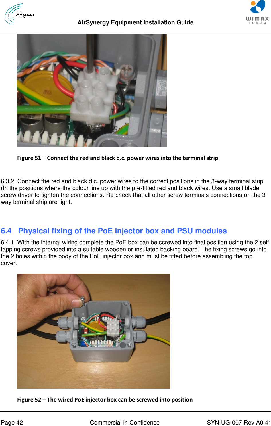
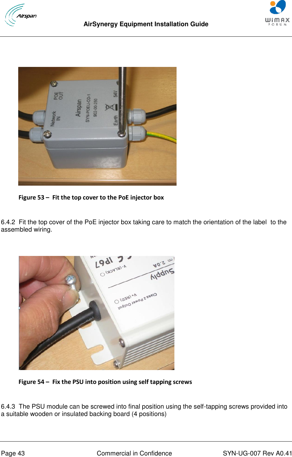
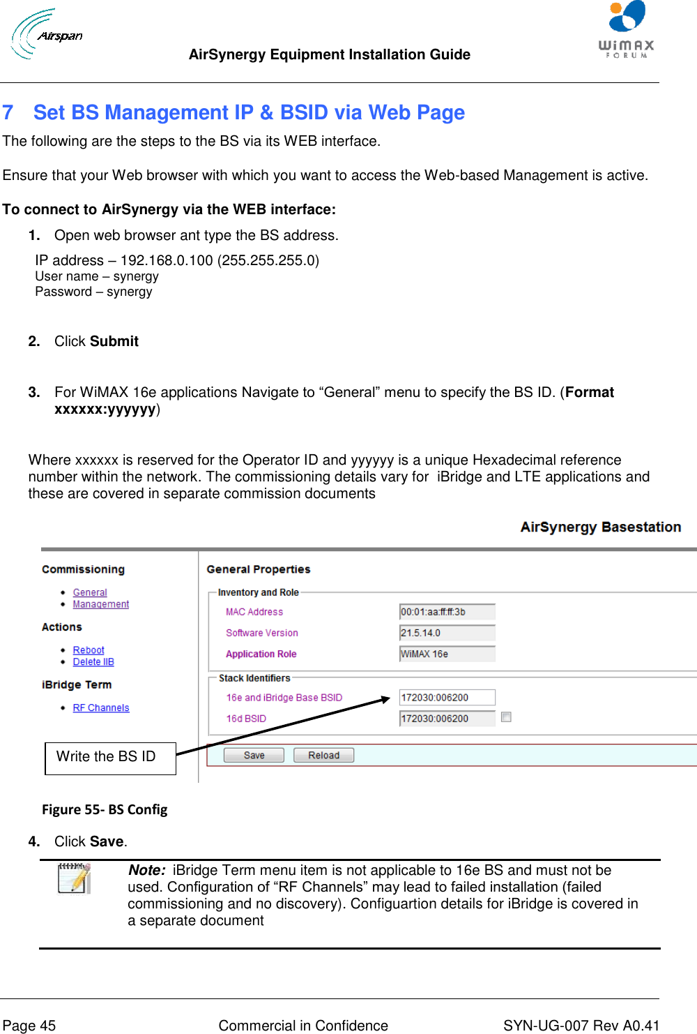
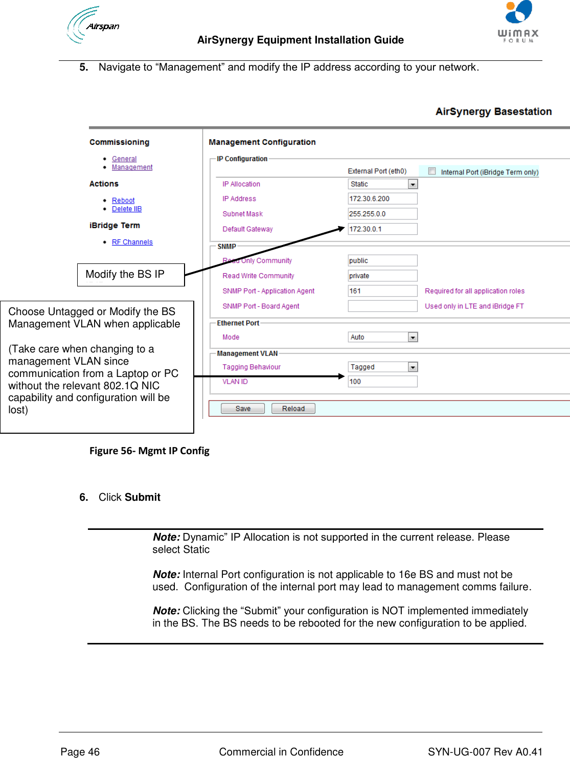
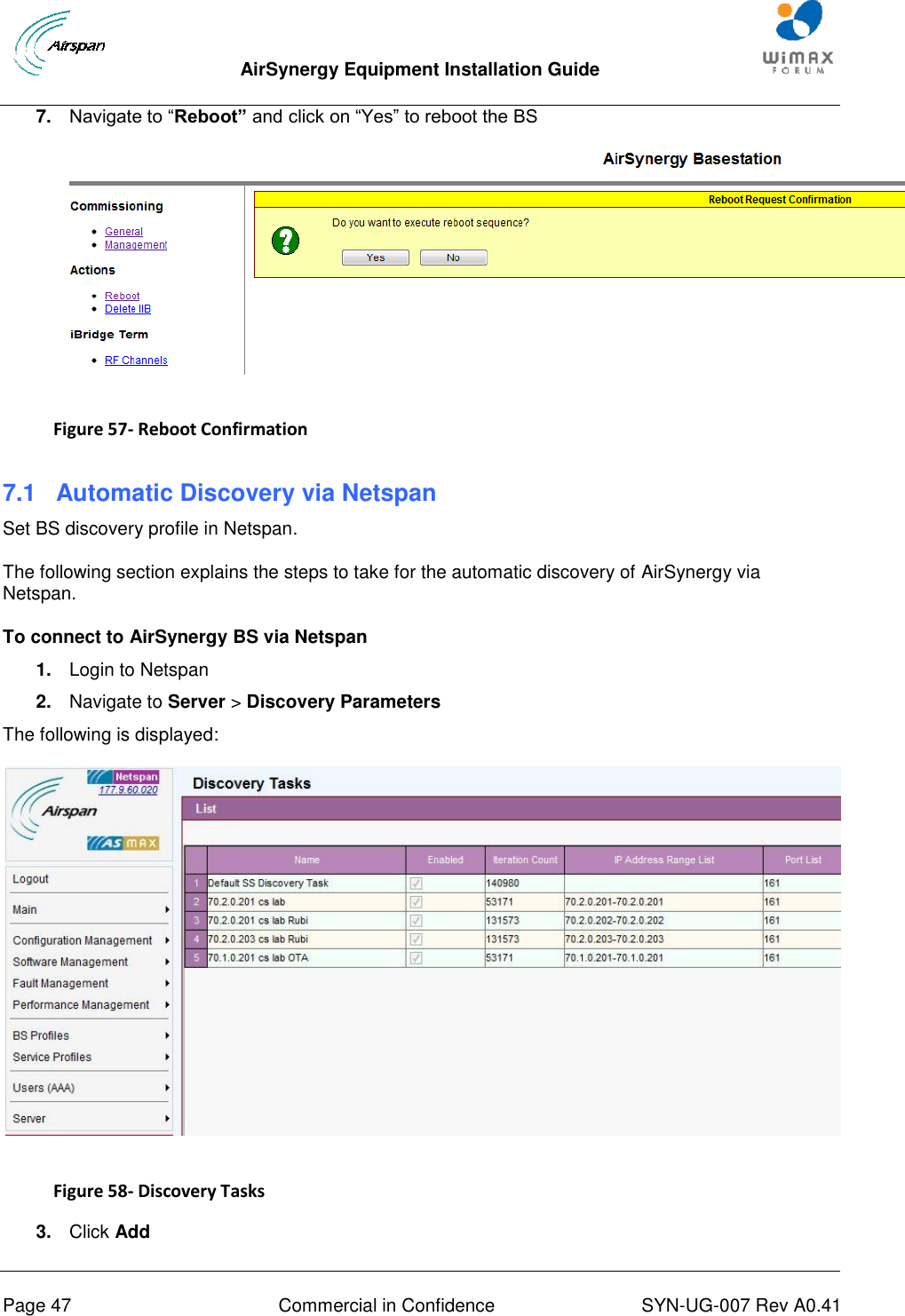
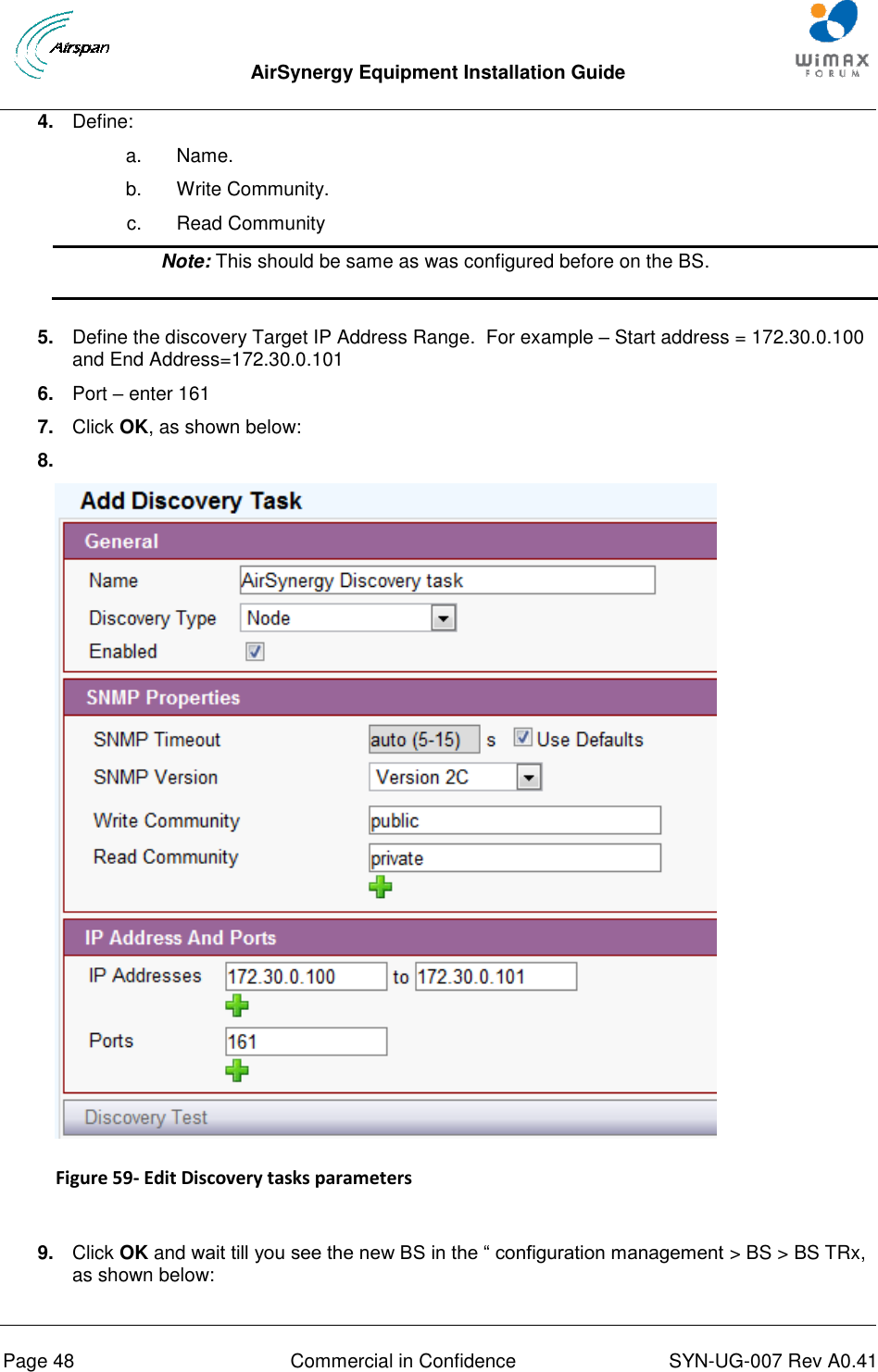
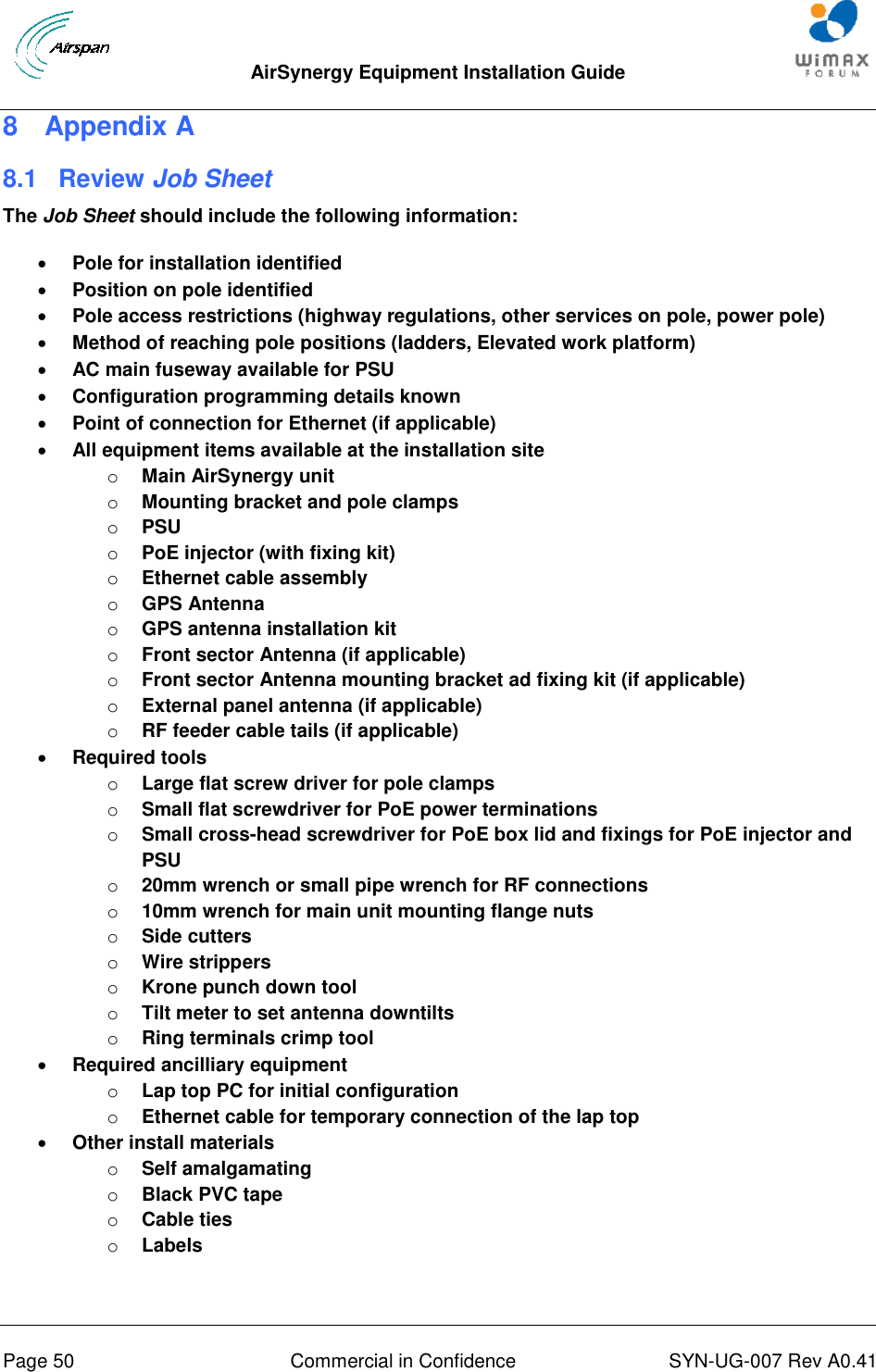
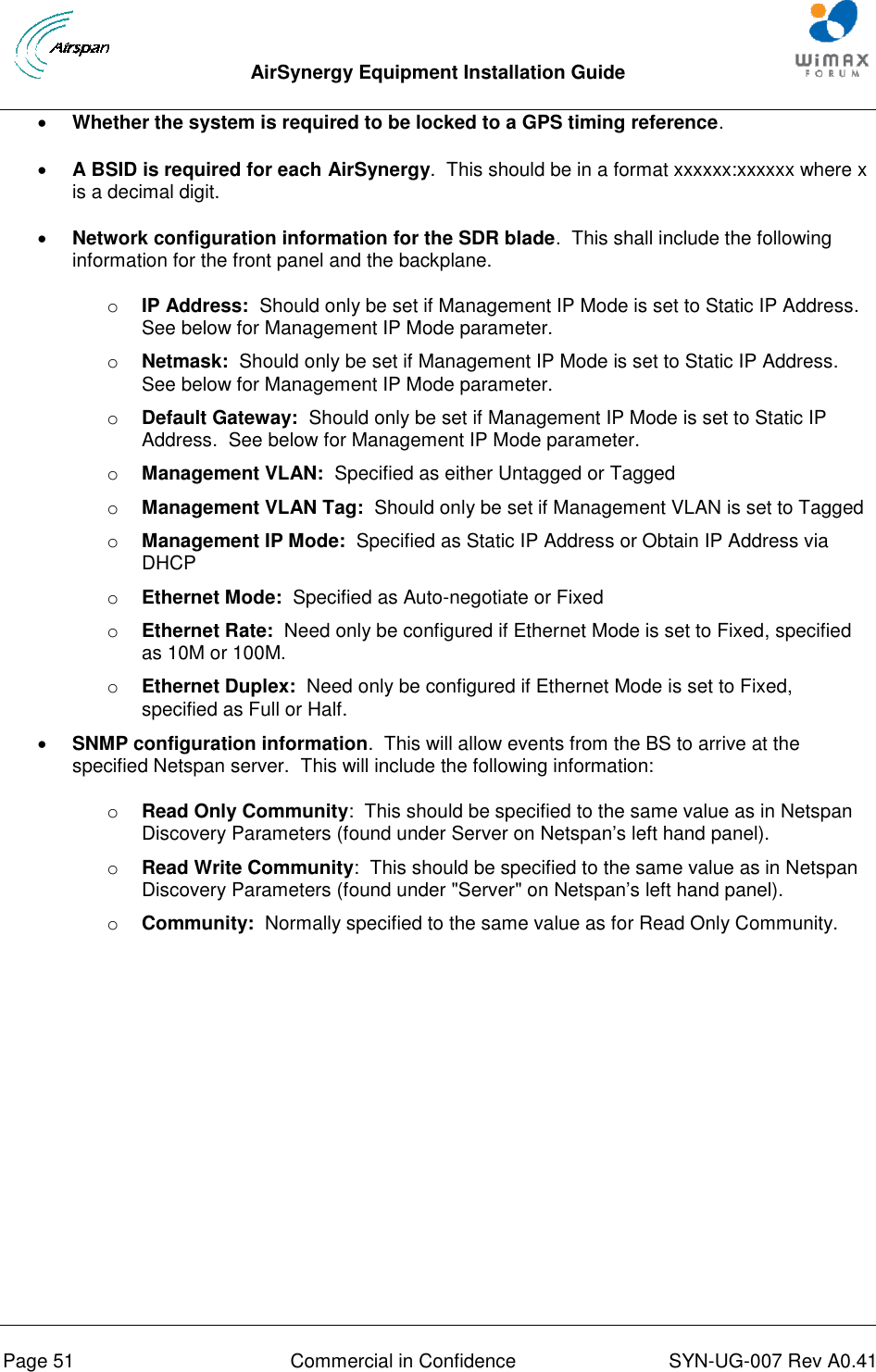
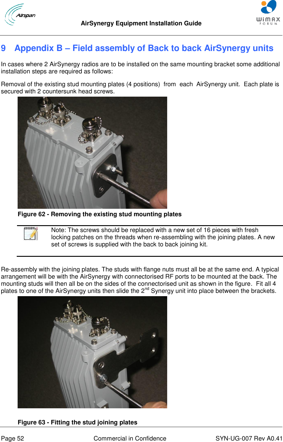
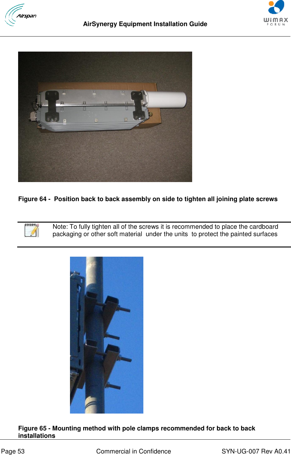
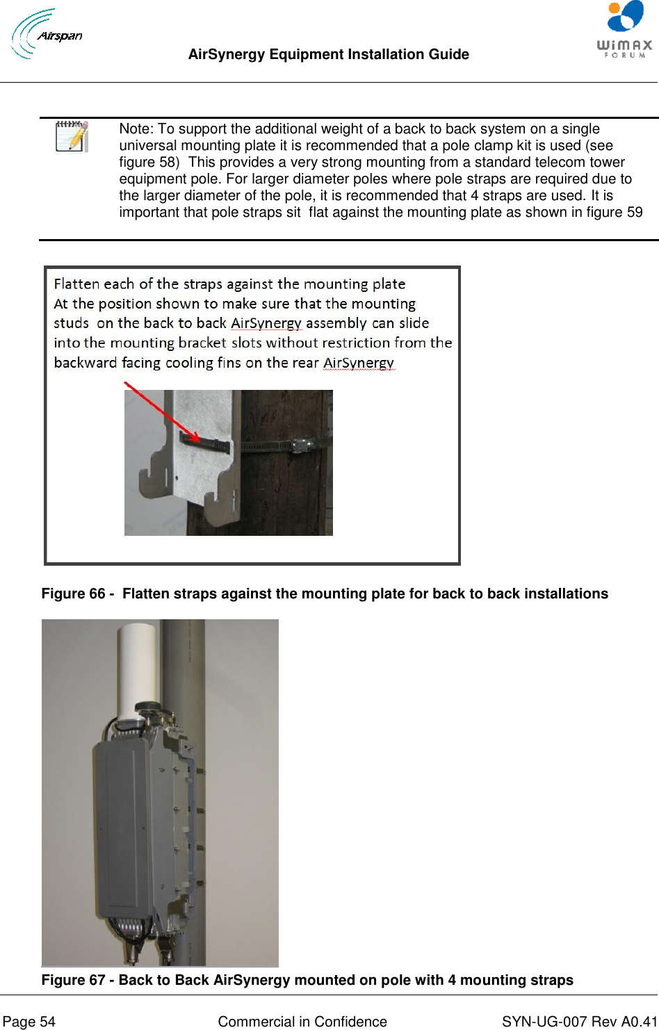
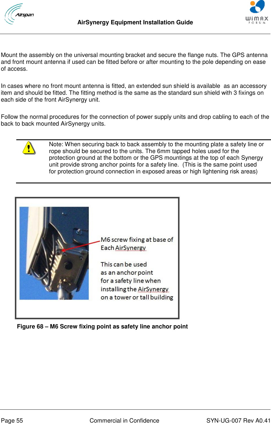
Installation Guide