Airspan Communications 495AS Airsynergy Compact Outdoor Pico Base Station User Manual Installation Guide
Airspan Communications Limited Airsynergy Compact Outdoor Pico Base Station Installation Guide
Contents
- 1. Installation Guide
- 2. Additional User Manual Statement
Installation Guide

SYN-UG-007 Revision A0.41
AirSynergy
Equipment
Installation Guide

AirSynergy Equipment Installation Guide
Page 2 Commercial in Confidence SYN-UG-007 Rev A0.41
Copyright
© Copyright by Airspan Networks Inc., 2012. All rights reserved worldwide.
The information contained within this document is proprietary and is subject to all relevant copyright,
patent and other laws protecting intellectual property, as well as any specific agreements protecting
Airspan Networks Inc. rights in the aforesaid information. Neither this document nor the information
contained herein may be published, reproduced or disclosed to third parties, in whole or in part,
without the express, prior, written permission of Airspan Networks Inc. In addition, any use of this
document or the information contained herein for the purposes other than those for which it is
disclosed is strictly forbidden.
Airspan Networks Inc. reserves the right, without prior notice or liability, to make changes in
equipment design or specifications.
Information supplied by Airspan Networks Inc. is believed to be accurate and reliable. However, no
responsibility is assumed by Airspan Networks Inc. for the use thereof nor for the rights of third parties
which may be effected in any way by the use of thereof.
Any representation(s) in this document concerning performance of Airspan Networks Inc. product(s)
are for informational purposes only and are not warranties of future performance, either expressed or
implied. Airspan Networks Inc. standard limited warranty, stated in its sales contract or order
confirmation form, is the only warranty offered by Airspan Networks Inc. in relation thereto.
This document may contain flaws, omissions or typesetting errors; no warranty is granted nor liability
assumed in relation thereto unless specifically undertaken in Airspan Networks Inc. sales contract or
order confirmation. Information contained herein is periodically updated and changes will be
incorporated into subsequent editions. If you have encountered an error, please notify Airspan
Networks Inc. All specifications are subject to change without prior notice.
Product performance figures quoted within this document are indicative and for information purposes
only.
UK WEE Registration number: WEE/AB0207WZ

AirSynergy Equipment Installation Guide
Page 3 Commercial in Confidence SYN-UG-007 Rev A0.41
Table of Contents
Copyright ................................................................................................................................................. 2
Table of Contents .................................................................................................................................... 3
Summary of Figures ................................................................................................................................ 5
Summary of Tables ................................................................................................................................. 8
1 About this Guide .............................................................................................................................. 9
1.1 Purpose ................................................................................................................................... 9
1.2 Intended Audience .................................................................................................................. 9
1.3 Conventions ............................................................................................................................ 9
1.4 Referenced Documentation .................................................................................................. 10
1.5 Organisation of this Guide ..................................................................................................... 10
2 Introduction .................................................................................................................................... 11
2.1 General Overview for use with External Antenna ................................................................. 11
2.1.1 Front Mounted Sector Antenna Arrangement ............................................................... 11
2.1.2 Switched Beam Antenna Arrangement ......................................................................... 12
2.1.3 Dual unit arrangement ................................................................................................... 12
3 Get Started .................................................................................................................................... 13
3.1 Workflow of Installation ......................................................................................................... 13
3.2 Installation Checklist ............................................................................................................. 14
3.3 Verify Site Requirements ...................................................................................................... 14
3.4 Verify Safety Requirements .................................................................................................. 14
3.4.1 Warning of Hazardous Voltages ................................................................................... 14
3.4.2 Adhere to European Directive 1999/519/EC ................................................................. 15
3.5 Verify Installation Requirements ........................................................................................... 15
3.5.1 Verify the Tools ............................................................................................................. 15
3.5.2 Verify the Parts and Kits ................................................................................................ 16
3.5.3 Verify Components ........................................................................................................ 19

AirSynergy Equipment Installation Guide
Page 4 Commercial in Confidence SYN-UG-007 Rev A0.41
4 Installing AirSynergy ..................................................................................................................... 22
4.1 Mount the AirSynergy Universal Mounting Plate .................................................................. 22
4.2 Fit Front Sector Antenna to AirSynergy ................................................................................ 24
4.3 Fit GPS Antenna to AirSynergy............................................................................................. 25
4.4 Secure AirSynergy and Antenna to pole mount plate ........................................................... 26
5 Connect and Manage cables ........................................................................................................ 29
5.1 Fitting the Protection earth cable .......................................................................................... 29
5.2 Connecting RF Jumper cables to External Antenna ............................................................. 31
5.3 Connect PoE drop cable to the AirSynergy .......................................................................... 32
6 Connect to Power System ............................................................................................................. 33
6.1 Run cables from the PoE injector to the AirSynergy ............................................................. 33
6.2 Wiring of the Drop cable and Network cables to the PoE injector ........................................ 35
6.3 Connecting the d.c. PSU ....................................................................................................... 41
6.4 Physical fixing of the PoE injector box and PSU modules .................................................... 42
7 Set BS Management IP & BSID via Web Page ............................................................................ 45
7.1 Automatic Discovery via Netspan ......................................................................................... 47
8 Appendix A .................................................................................................................................... 50
8.1 Review Job Sheet ................................................................................................................. 50
9 Appendix B – Field assembly of Back to back AirSynergy units ................................................... 52
10 Appendix C – Glossary of Terms ............................................................................................. 56
11 Appendix D – Checklist ............................................................................................................. 57
12 Appendix E – PSU for USA ....................................................................................................... 58
13 Appendix F – FCC Requirements ............................................................................................. 60
14 Appendix G – Declaration of Conformance (CE) for Airsynergy ............................................... 64
15 Appendix H - Document Status ................................................................................................. 66
15.1 Revision History .................................................................................................................... 66

AirSynergy Equipment Installation Guide
Page 5 Commercial in Confidence SYN-UG-007 Rev A0.41
Summary of Figures
Figure 1 – Typical AirSynergy with sun shield ..................................................................................... 11
Figure 2 – AirSynergy with front sector antenna fitted .......................................................................... 11
Figure 3– AirSynergy with Switched Beam Antenna ............................................................................ 12
Figure 4 – AirSynergy dual unit “back to back” configuration (External GPS antenna fitted) ............... 12
Figure 5 – Workflow of AirSynergy Installation .................................................................................... 13
Figure 6 – AirSynergy unit in typical packing box as supplied .............................................................. 19
Figure 7 – AirSynergy unit (connectorised) .......................................................................................... 19
Figure 8 – AirSynergy unit with Switched Beam Antenna (factory fitted) ............................................. 19
Figure 9 – Universal Mounting Plate and pole straps .......................................................................... 20
Figure 10 – Sun Shield with fixings ....................................................................................................... 20
Figure 11 – Sector Antenna Mounting plate and fixings ....................................................................... 20
Figure 12 – Sector Antenna (Check frequency variants) ...................................................................... 20
Figure 13 – GPS antenna ..................................................................................................................... 21
Figure 14 – GPS antenna mounting kit ................................................................................................. 21
Figure 15 – AirSynergy mounting plate and fixings ............................................................................ 22
Figure 16 – Feed clamp bands through the quick release locking mechanisms ................................. 22
Figure 17 – Press down the locking mechanism with the slack band fed through .............................. 22
Figure 18 – Tighten clamps with large flat blade screwdriver ............................................................... 23
Figure 19 – AirSynergy mounting plate installed (large diameter concrete pole) ................................. 23
Figure 20 – Fixing the front mount antenna to the mounting plate ....................................................... 24
Figure 21 –Fitting the Front mount antenna assembly to AirSynergy .................................................. 24
Figure 22 –Fitting the GPS antenna to the mounting bracket ............................................................... 25
Figure 23 –GPS antenna cable connected ........................................................................................... 25
Figure 24 – Assembling the GPS antenna and bracket assembly to AirSynergy ................................. 26
Figure 25 – Lift AirSynergy to top of pole-mount plate ........................................................................ 26
Figure 26 – AirSynergy drops down into slots at the top of pole-mount plate .................................... 27

AirSynergy Equipment Installation Guide
Page 6 Commercial in Confidence SYN-UG-007 Rev A0.41
Figure 27 – Gently lift the AirSynergy body until the bottom studs engage in the bottom slots .......... 27
Figure 28 – AirSynergy body engaged in the bottom slots ................................................................... 27
Figure 29 – AirSynergy downtilt adjustment ......................................................................................... 28
Figure 30 – Tighten flange nuts (4 positions) once the required mounting angle is set ....................... 28
Figure 31– AirSynergy attachment of earthing cable ........................................................................... 29
Figure 32– Attach earth cable to pole ................................................................................................... 29
Figure 33 – Connecting the antenna RF cables .................................................................................. 31
Figure 34 – AirSynergy Front mount antenna connections – applying self -amalgamating tape ......... 31
Figure 35 – AirSynergy antenna connections – applying PVC tape .................................................... 32
Figure 36 – Attach PoE drop cable to the AirSynergy .......................................................................... 32
Figure 37 – Tools required to connect the PoE injector and PSU ........................................................ 33
Figure 38 – AirSynergy power and network cable overview diagram ................................................... 35
Figure 39 – Preparing the drop cable/network cable wire ends for connection into the PoE injector .. 35
Figure 40 – Twist the individual drain wire strands together ................................................................ 36
Figure 41 – Pass the network cable /drop cable end through the end cap of a PoE gland ................ 36
Figure 42 – Pass the cable through the gland and tighten the end cap ............................................... 36
Figure 43 – View of the PoE injector lid indicating the 4 cable gland positions .................................... 37
Figure 44 – Position the individual pairs in the punch down strip ......................................................... 38
Figure 45 – The punch down orientation .............................................................................................. 39
Figure 46 – Continue dressing and punching down each coloured pair ............................................... 39
Figure 47 – Push green/yellow plastic sleeves over the drain wire ...................................................... 40
Figure 48 – Connect the drain wires to the earth terminal .................................................................... 40
Figure 49 – Pass the d.c. power cable end through the end cap of a PoE gland................................ 41
Figure 50 – Pass the d.c. power cable through the gland and tighten the end cap.............................. 41
Figure 51 – Connect the red and black d.c. power wires into the terminal strip ................................... 42
Figure 52 – The wired PoE injector box can be screwed into position ................................................. 42
Figure 53 – Fit the top cover to the PoE injector box ........................................................................... 43

AirSynergy Equipment Installation Guide
Page 7 Commercial in Confidence SYN-UG-007 Rev A0.41
Figure 54 – Fix the PSU into position using self tapping screws ......................................................... 43
Figure 55- BS Config ............................................................................................................................. 45
Figure 56- Mgmt IP Config .................................................................................................................... 46
Figure 57- Reboot Confirmation ............................................................................................................ 47
Figure 58- Discovery Tasks .................................................................................................................. 47
Figure 59- Edit Discovery tasks parameters ......................................................................................... 48
Figure 60 - Discovery Target................................................................................................................. 49
Figure 61 - Discovery Test .................................................................................................................... 49
Figure 62 - Removing the existing stud mounting plates ...................................................................... 52
Figure 63 - Fitting the stud joining plates .............................................................................................. 52
Figure 64 - Position back to back assembly on side to tighten all joining plate screws....................... 53
Figure 65 - Mounting method with pole clamps recommended for back to back installations ............. 53
Figure 66 - Flatten straps against the mounting plate for back to back installations ........................... 54
Figure 67 - Back to Back AirSynergy mounted on pole with 4 mounting straps ................................... 54
Figure 68 – M6 Screw fixing point as safety line anchor point.............................................................. 55
Figure 69 – AirSynergy Mains PSU and enclosure for USA deployments ........................................... 58
Figure 70 – 48V DC cable attached ready for connection to the PoE injector ..................................... 58
Figure 71 – Internal PSU and and cable terminations .......................................................................... 59

AirSynergy Equipment Installation Guide
Page 8 Commercial in Confidence SYN-UG-007 Rev A0.41
Summary of Tables
Table 1 - AirSynergy installation tools ................................................................................................... 15
Table 2 – AirSynergy installation parts and kits .................................................................................... 16
Table 3 – External Antenna and feeder kits (OPTION) ....................................................................... 18
Table 4 - AirSynergy additional (consumable) items .......................................................................... 18
AirSynergy Equipment Installation Guide
Page 9 Commercial in Confidence SYN-UG-007 Rev A0.41
1 About this Guide
This section discusses the purpose, intended audience, conventions, referenced documentation and
organisation for this guide.
1.1 Purpose
This guide provides the workflow and step-by-step procedures for Installation of the AirSynergy
equipment. These procedures include:
Verify Prerequisites
Install the AirSynergy Radio equipment
Install the PSU equipment
Connect and manage cables
Commission and discover via Netspan, to be ready for full configuration
1.2 Intended Audience
This guide is intended for persons who are responsible for installing the AirSynergy equipment.
These persons should have a working knowledge of the equipment.
1.3 Conventions
This document uses the following informational conventions.
Icon
Description
Checkpoint: Marks a point in the workflow where there may be an exit or branch
to some other procedure. At each Checkpoint the reason for an exit or branch is
given along with specific directions to locate the entry point in the other
procedure.
Reference: Gives a resource in the workflow that may be needed to complete a
procedure along with specific directions to use the resource.
Caution: Describes a possible risk and how to lessen or avoid the risk.
Advice: Provides a recommendation based on best practice.
Note: Provides useful information.

AirSynergy Equipment Installation Guide
Page 10 Commercial in Confidence SYN-UG-007 Rev A0.41
1.4 Referenced Documentation
Place holder for Product Bulletins and other related documents
1.5 Organisation of this Guide
This guide is organised into the following Sections:
About this Guide
Introduction
Get Started
Verify Prerequisites
Install the AirSynergy Radio equipment
Install the PSU equipment
Connect and manage cables
Set BS Management IP & BSID via Web Page
Connect and manage cables
Appendixes
AirSynergy Equipment Installation Guide
Page 11 Commercial in Confidence SYN-UG-007 Rev A0.41
2 Introduction
This section provides a descriptive overview of the product.
2.1 General Overview for use with External Antenna
AirSynergy equipment comes in a range of frequency variants that can be mounted with different
antenna options and formats.
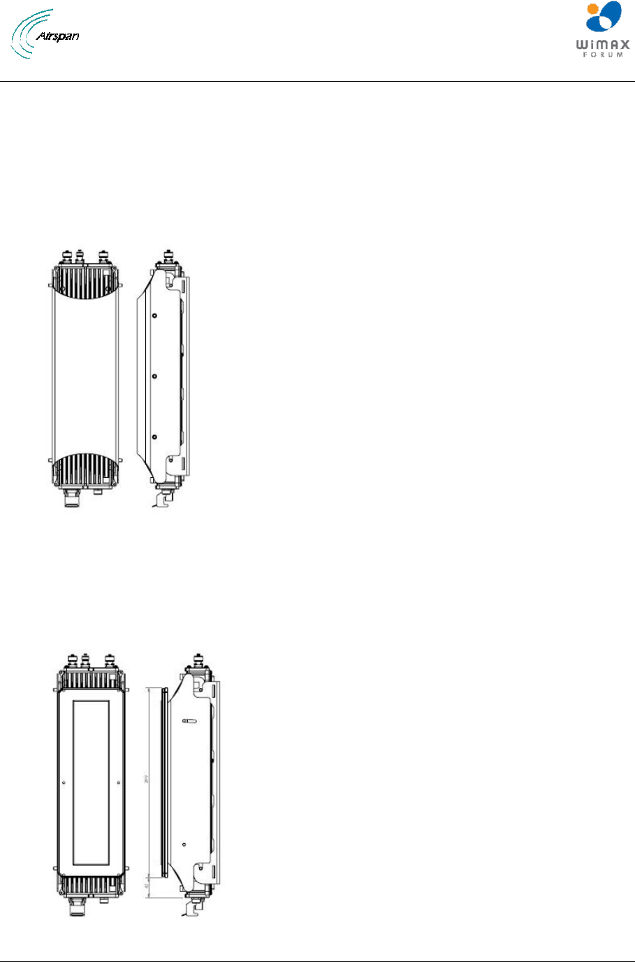
Figure 1 – Typical AirSynergy with sun shield
2.1.1 Front Mounted Sector Antenna Arrangement
A typical sector installation will have a cross-polar sector antenna fitted directly to the front of the
AirSynergy main unit. (This is fitted instead of the sun-shield).
Figure 2 – AirSynergy with front sector antenna fitted
AirSynergy Equipment Installation Guide
Page 12 Commercial in Confidence SYN-UG-007 Rev A0.41
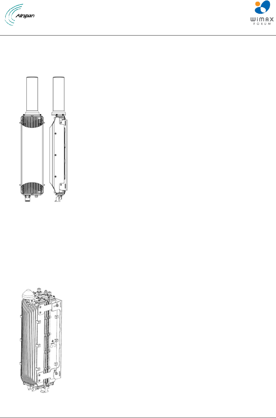
2.1.2 Switched Beam Antenna Arrangement
A switched beam antenna version (factory built option) with built in GPS antenna allows for flexible
iBridge backhaul functionality where the strongest signal from any direction is automatically selected.
The same antenna can also be configured in omni mode for the support of access.
Figure 3– AirSynergy with Switched Beam Antenna
2.1.3 Dual unit arrangement
AirSynergy units may be mounted together in a dual arrangement on the same mounting plate
utilising a special joining kit (supplied as a separate accessory).
Note: Various antenna options can be selected for each AirSynergy to perform the required
combination of backhaul and access functionality. An extended sun-shield is also available for this
format.
Figure 4 – AirSynergy dual unit “back to back” configuration (External GPS antenna
fitted)
AirSynergy Equipment Installation Guide
Page 13 Commercial in Confidence SYN-UG-007 Rev A0.41
3 Get Started
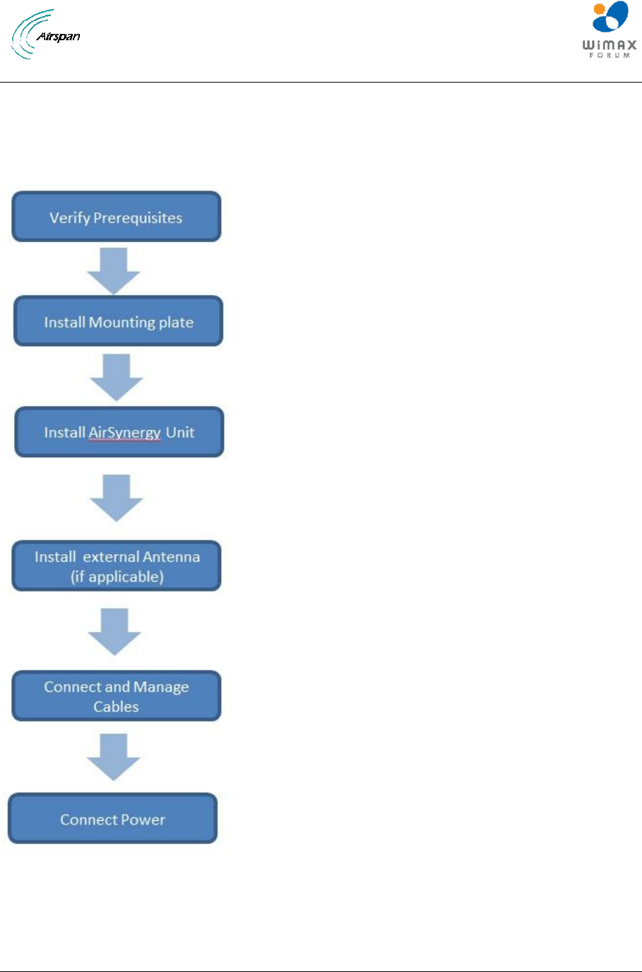
3.1 Workflow of Installation
The workflow required to install the AirSynergy equipment is shown in the following diagram:
Figure 5 – Workflow of AirSynergy Installation

AirSynergy Equipment Installation Guide
Page 14 Commercial in Confidence SYN-UG-007 Rev A0.41
3.2 Installation Checklist
Plan the installation of the AirSynergy Unit by using the Installation Checklist in Appendix A
3.3 Verify Site Requirements
To set up the AirSynergy a connection to a Netspan server PC will be required.
3.4 Verify Safety Requirements
Read and follow all warning notices and instructions marked on the product or included in this
manual.
When installed in the final configuration, the product must comply with the applicable Safety
Standards and regulatory requirements of the country in which it is installed. If necessary, consult with
the appropriate regulatory agencies and inspection authorities to ensure compliance.
Ascertain the radiation hazards when working in an environment close to other antennas and
Electromagnetic fields, e.g. working on towers with other microwave transmitters etc. and act
accordingly.
3.4.1 Warning of Hazardous Voltages
On AC installations, hazardous voltages exist. Use caution when verifying or working with AC power.
Remove metal jewellery that could come into contact with AC power.
On DC sections, short circuiting the low voltage, low impedance circuits can cause arcing that may
result in burns or eye damage. Remove rings, watches etc. to avoid shorting DC circuits.
Note: Airspan products do not contain hazardous substances (as defined in UK
Control of Substances Hazardous to Health Regulations 1989 and the Dangerous
Substances Regulations 1990). At the end of any Airspan products life cycle, the
customer should consult with Airspan to ensure that the product is disposed of in
conformance with the relevant regulatory requirements.
Caution: Any modifications to this device not expressly authorised by the
manufacturer could void the users’ authority to operate this device.

AirSynergy Equipment Installation Guide
Page 15 Commercial in Confidence SYN-UG-007 Rev A0.41
3.4.2 Adhere to European Directive 1999/519/EC
European Council Recommendation1999/519/EC details basic restrictions and reference levels on
human exposure to electromagnetic fields as advised by the ICNIRP. Adherence to these
recommended restrictions and reference levels should provide a high level of protection as regards
the established health effects that may result from exposure to electromagnetic fields.
3.5 Verify Installation Requirements
3.5.1 Verify the Tools
Table 1 - AirSynergy installation tools
Tools
Small flat blade Screwdriver
(For screw terminals inside PoE injector)
Large Flat Bladed Screwdriver
(Securing of the pole straps)
Medium Cross-head Screwdriver
(PoE injector lid and mounting screws)
13mm wrench x 2
(Heavy-duty pole clamp option only)
10mm wrench
(AirSynergy securing flange nuts)
Large pliers
(Tightening cable glands on the PoE injector - To fit 15mm across flats)
Knife (for stripping back insulation)
Tweezers (or fine tipped long nose pliers)
Wire cutters
Wire strippers
(Cutting insulation)
Ring terminals crimp tool

AirSynergy Equipment Installation Guide
Page 16 Commercial in Confidence SYN-UG-007 Rev A0.41
Tools
Tilt-meter
(If accurate downtilt of antenna needs to be set)
Krone punch-down tool
(Termination of Ethernet cables in PoE injector)
3.5.2 Verify the Parts and Kits
Table 2 – AirSynergy installation parts and kits
Installation Kit /
Part:
Installation Kit details
Note:
Main AirSynergy
parts
1 x AirSynergy Universal
Mounting Plate and pole strap
kit
(Includes 2 pole straps for poles
up to 200mm diameter)
AirSynergy unit(s)
Frequency band specific and
available with and without
integral switched beam antenna.
Check against order and
requirement to ensure the
correct unit type to be installed
Either of the following:
1 x Sun Shield (for single unit
installation where a separately
mounted external antenna is
deployed)
Sun shield
6 Countersunk head fixing
screws
OR (for front mount antenna
option)
1 x Sector Antenna mounting
plate with fixing kit
4 M4 nuts
4 M4 flat washers
4 M4 spring washers
4 Cable ties
4 M5 SEM

AirSynergy Equipment Installation Guide
Page 17 Commercial in Confidence SYN-UG-007 Rev A0.41
1 x Sector Antenna (front
mounting)
Additionally required for any
non-switched beam antenna
versions of AirSynergy
GPS Antenna
GPS Antenna mounting kit
Bracket
M6 screw
M6 plain washer
M6 spring washer
TNC to TNC cable (25cm)
Additionally required for back to
back unit installations
1 x back to back joining kit
4 joining straps with mounting
studs and flange nuts pre-fitted.
16 M5 countersink scres
1 x Extended sun shield ( If no
front mount antenna is to be
fitted to the front face of the
back to back AirSynergy units)
OPTIONAL Heavy-
duty mounting (for
specific mounting
locations)
1 heavy-duty pole clamp
mounting kit
4 clamps
4 M8x150 bolts
4 M8 plain washer
4 M8 spring washer
Connecting cables
CAT5e
External grade 25m with weather
hood pre-fitted. One for each
AirSynergy unit
Earthing cable
M6 Lug at each end
Power Supply and
PoE
48V PSU module
1 per AirSynergy unit
PoE injector
1 per AirSynergy unit
48V PSU in weatherproof
enclosure (NEMA 4X)
Alternative to the standard 48V
PSU and is required for all North
American installations

AirSynergy Equipment Installation Guide
Page 18 Commercial in Confidence SYN-UG-007 Rev A0.41
Table 3 – External Antenna and feeder kits (OPTION)
Installation Kit / Part
Note
External Antenna
Many variants - Check against
order and requirement to ensure
the correct type is installed
Typically a 2 port cross-polar antenna
Pole mounting kits (supplied with antenna)
Short Feeder cable
0.5M feeder tails x 2 (Suitable for mounting
antenna directly above the AirSynergy unit)
Long Feeder tail
1.5M feeder tails x2 (Suitable for mounting
antenna on the same pole immediately behind the
AirSynergy unit or where the Antenna needs to be
spaced away from the AirSynergy unit)
Table 4 - AirSynergy additional (consumable) items
Additional items (not provided by Airspan)
Cable ties
Self-amalgamating tape
Black PVC tape
Ring terminal for earth strap, M6
Earth strap cable (4mm), yellow and green cable
AirSynergy Equipment Installation Guide
Page 19 Commercial in Confidence SYN-UG-007 Rev A0.41
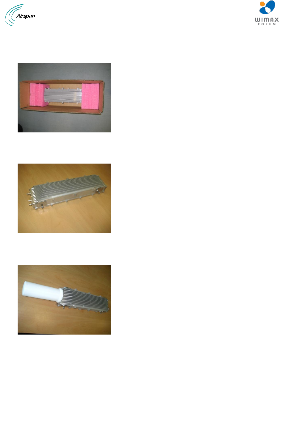
3.5.3 Verify Components
The following figures show and describe the AirSynergy components and accessory kits
Figure 6 – AirSynergy unit in typical packing box as supplied
Figure 7 – AirSynergy unit (connectorised)
Figure 8 – AirSynergy unit with Switched Beam Antenna (factory fitted)
AirSynergy Equipment Installation Guide
Page 20 Commercial in Confidence SYN-UG-007 Rev A0.41
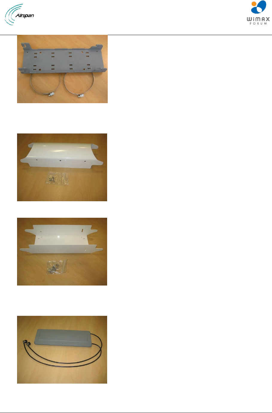
Figure 9 – Universal Mounting Plate and pole straps
Figure 10 – Sun Shield with fixings
Figure 11 – Sector Antenna Mounting plate and fixings
Figure 12 – Sector Antenna (Check frequency variants)
AirSynergy Equipment Installation Guide
Page 21 Commercial in Confidence SYN-UG-007 Rev A0.41
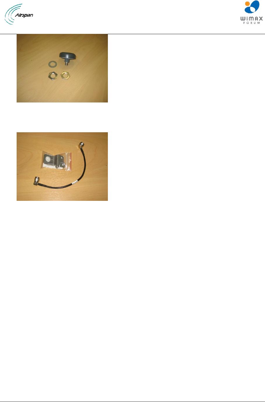
Figure 13 – GPS antenna
Figure 14 – GPS antenna mounting kit
AirSynergy Equipment Installation Guide
Page 22 Commercial in Confidence SYN-UG-007 Rev A0.41
4 Installing AirSynergy
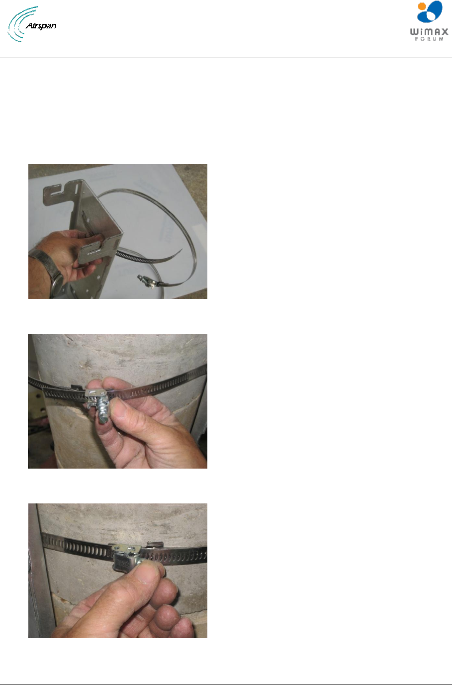
4.1 Mount the AirSynergy Universal Mounting Plate
The AirSynergy is normally mounted on a pole (in close proximity to its external antenna if not using
the AirSynergy front mounted Antenna. Take care to install the mounting plate the correct way up so
that the AirSynergy unit will fit with the PoE connector pointing downwards. This is with the slot
openings in the bracket at the top edges as shown.
Figure 15 – AirSynergy mounting plate and fixings
Figure 16 – Feed clamp bands through the quick release locking mechanisms
Figure 17 – Press down the locking mechanism with the slack band fed through
AirSynergy Equipment Installation Guide
Page 23 Commercial in Confidence SYN-UG-007 Rev A0.41
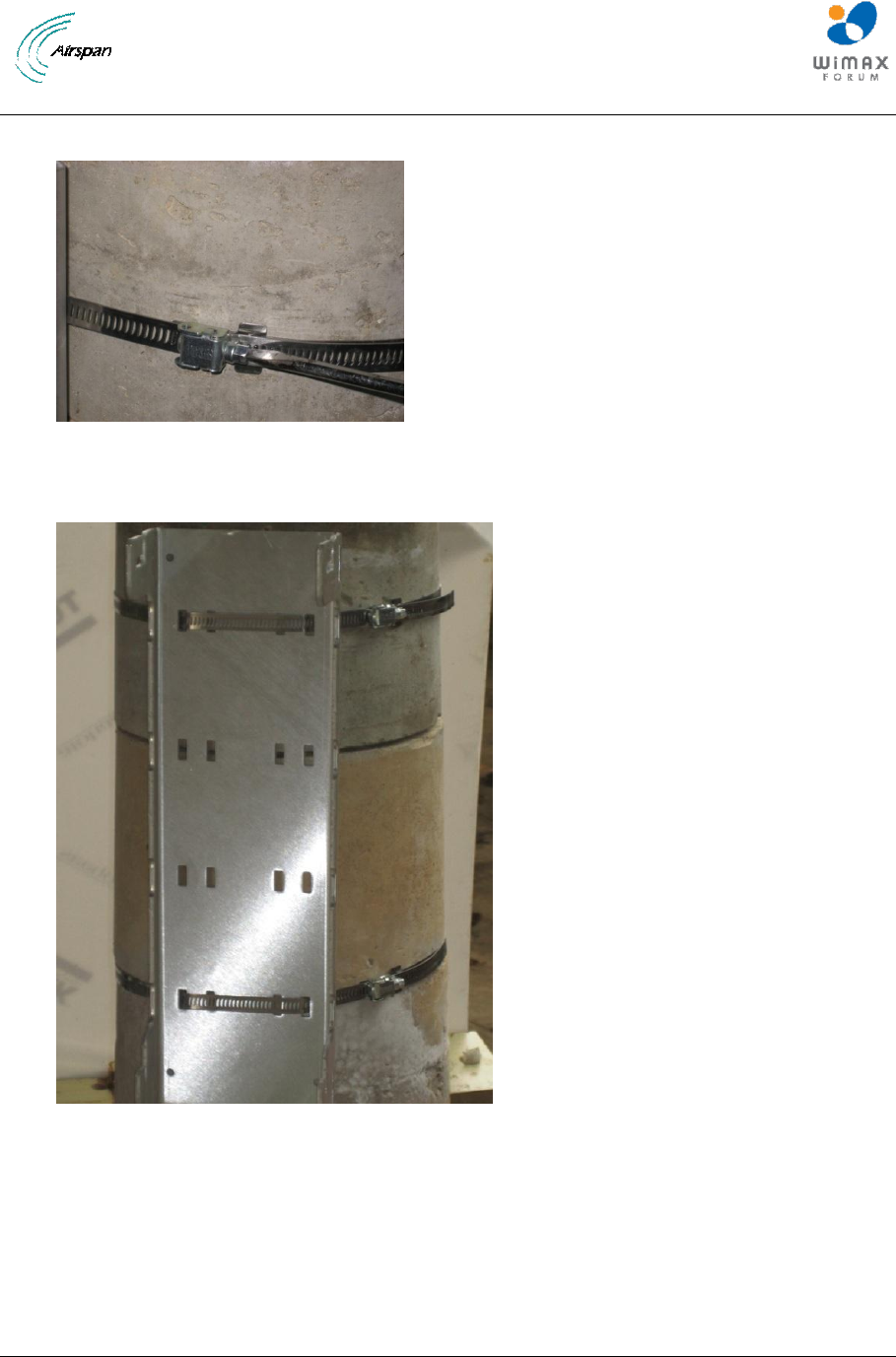
Figure 18 – Tighten clamps with large flat blade screwdriver
Figure 19 – AirSynergy mounting plate installed (large diameter concrete pole)
AirSynergy Equipment Installation Guide
Page 24 Commercial in Confidence SYN-UG-007 Rev A0.41
4.2 Fit Front Sector Antenna to AirSynergy
The AirSynergy unit can be used either with a sector antenna mounted directly on the front or with a
remotely attached RF antenna. This document describes the installation procedure for the front mount
antenna. For the installation of a separate antenna follow the antenna manufacturer’s instructions and
connect to the AirSynergy using suitable feeder cable tails. (N-Type RF connections should all be
weather-proofed). In all cases where a front mount antenna is not fitted a sun shield should be fitted.
To mount the front antenna, perform the following steps:
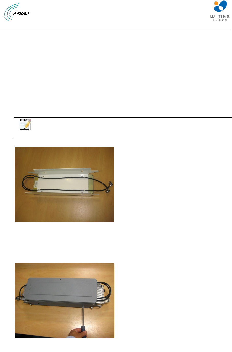
4.2.1 Fit the antenna to the mounting plate. The 4 studs on the back of the antenna pass through the
holes on the front face of the mounting plate and secure into position with the 4 sets of M4 nuts and
washers (plain + spring) provided in the kit. Carefully position the flying lead RF cables as shown in
Figure 20 and secure in place to the eyelets in the back of the mounting plate with cable ties
(provided). The cables are formed with a cross-over at the bottom
Note: It is recommended to place some cardboard or paper under the unit to
protect it from scratching.
Figure 20 – Fixing the front mount antenna to the mounting plate
4.2.2 Fit the assembled antenna and mounting plate to the AirSynergy unit using the M5 SEMs (2
each side) and connect the RF cables to the N type RF ports at the top of the AirSynergy.
Note: the plate is mounted with the side slots to the top so that the required down-tilt can be set.
Figure 21 –Fitting the Front mount antenna assembly to AirSynergy
AirSynergy Equipment Installation Guide
Page 25 Commercial in Confidence SYN-UG-007 Rev A0.41
4.3 Fit GPS Antenna to AirSynergy
Note: AirSynergy units without a factory fitted Switched Beam Antenna all require
a GPS antenna which comes in a kit with a mounting bracket and a 25cm cable.
A prime consideration for a GPS antenna is a clear view of the sky, preferably
360 degrees
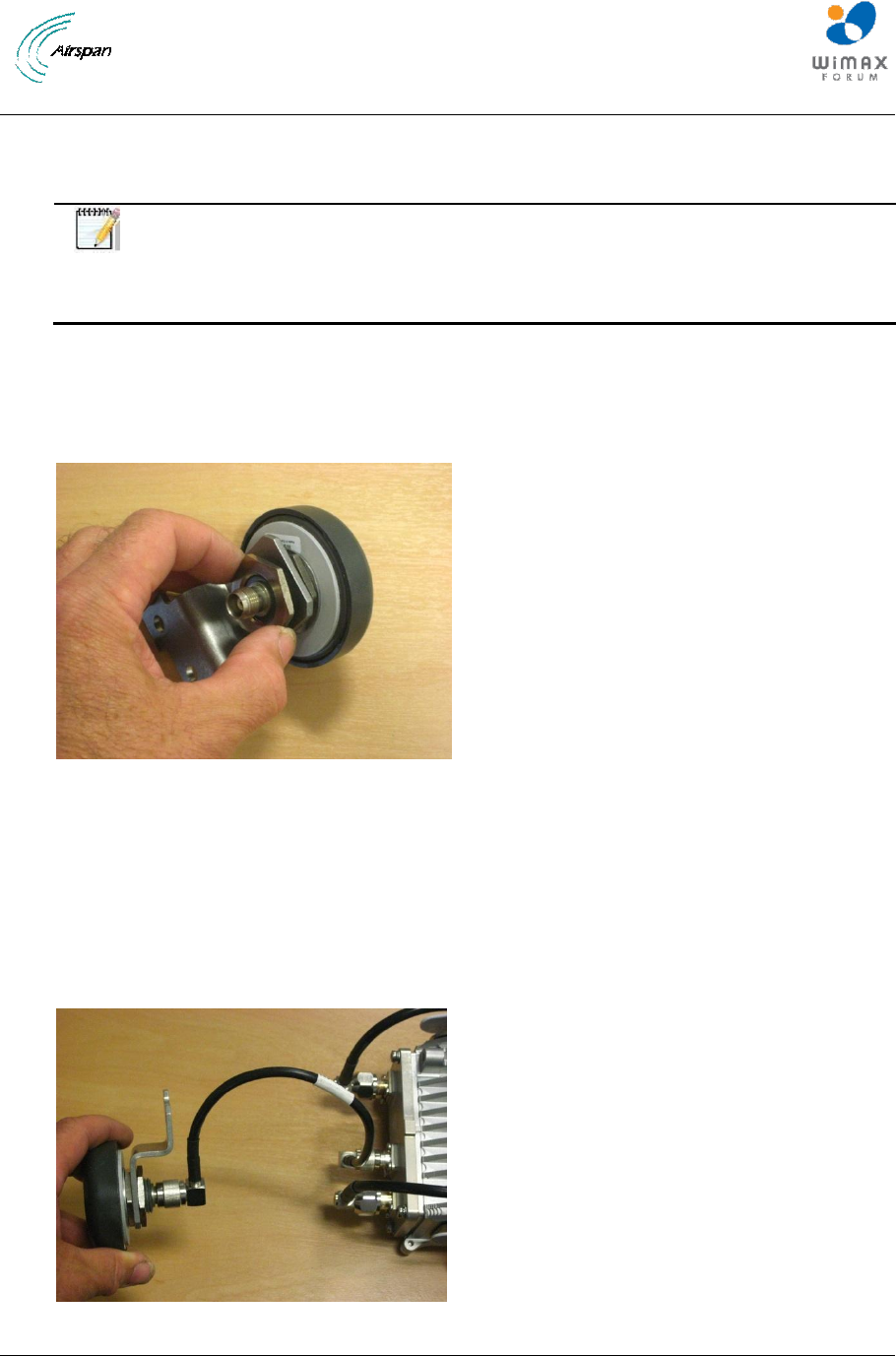
4.3.1 Fit the GPS antenna to the mounting bracket supplied in the GPS antenna mounting kit. The
large back nut should be tightened with a pipe wrench. Take care not to over tighten on the plastic
threads.
Figure 22 –Fitting the GPS antenna to the mounting bracket
4.3.2 Fit the short TNC to TNC cable from the GPS antenna to the TNC connector on the top of the
AirSynergy
Note: For extreme weather conditions weather-proofing of the TNC connections is recommended.
This is done with a layer of self-amalgamating tape followed by an over layer of PVC tape. The
weather-proofing is best done at this stage to give easier access to the connections
Figure 23 –GPS antenna cable connected
AirSynergy Equipment Installation Guide
Page 26 Commercial in Confidence SYN-UG-007 Rev A0.41
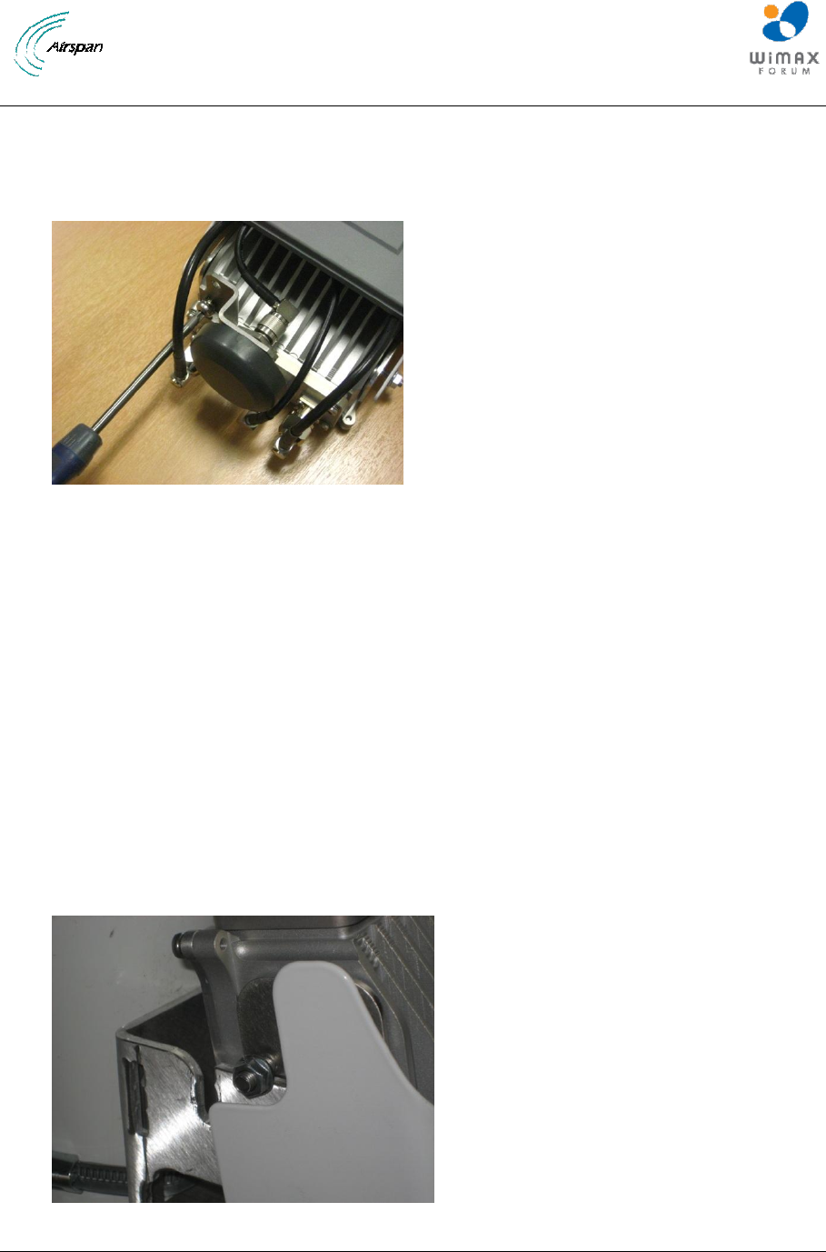
4.3.3 Fit the GPS antenna assembly to the body of the AirSynergy using the single M6 screw and
lock washer provided in the kit. There is a threaded hole at the top corner of the AirSynergy unit for
this purpose. The TNC to TNC cable loop can be gently positioned behind the front mount antenna (or
sunshield) as shown in Figure 24. Weather-proofing tapes (self -amalgamating followed by a layer of
black PVC tape) should be applied to the TNC connections.
Figure 24 – Assembling the GPS antenna and bracket assembly to AirSynergy
4.4 Secure AirSynergy and Antenna to pole mount plate
To mount AirSynergy to the universal mounting plate, perform the following steps:
NOTE: If the installation is for a back to back arrangement with 2 AirSynergy units sharing the
same mounting bracket refer to additional step in APPENDIX B.
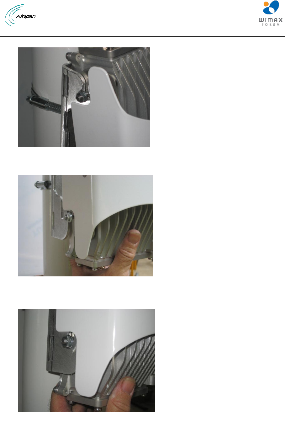
4.4.1 Hook the studs into the top slots of the mounting plate. With the studs engaged in the top
slots raise the unit slightly until the bottom studs also drop into their respective slots. Secure
the flange nuts (4 positions) with the require degree of down-tilt.
4.4.2 Follow the Figure sequence from Figure 25 to Figure 28 for the positioning of the AirSynergy
into the mounting bracket slots.
Figure 25 – Lift AirSynergy to top of pole-mount plate
AirSynergy Equipment Installation Guide
Page 27 Commercial in Confidence SYN-UG-007 Rev A0.41
Figure 26 – AirSynergy drops down into slots at the top of pole-mount plate
Figure 27 – Gently lift the AirSynergy body until the bottom studs engage in the bottom slots
Figure 28 – AirSynergy body engaged in the bottom slots
AirSynergy Equipment Installation Guide
Page 28 Commercial in Confidence SYN-UG-007 Rev A0.41
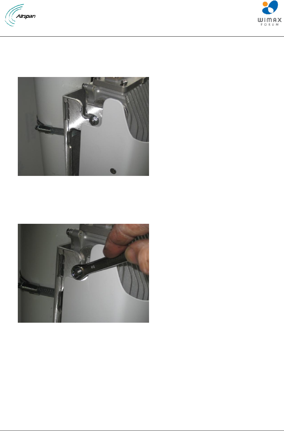
4.4.3 The slot arrangement at the top of the mounting bracket allows the AirSynergy and front
mounted antenna to be down-tilted by a few degrees or can be used to compensate for the taper
angle or tilt of the actual mounting pole. With the flange nuts gently hand tightened, the position can
be accurately set with tilt-meter on the front face of the AirSynergy unit.
Figure 29 – AirSynergy downtilt adjustment
4.4.4 The down-tilt angles are not marked by the adjustment slots so a tilt-meter is required
to set a specific angle, the flange nuts can then be tightened with a 10mm wrench on each
stud (4 positions)
Figure 30 – Tighten flange nuts (4 positions) once the required mounting angle is set
AirSynergy Equipment Installation Guide
Page 29 Commercial in Confidence SYN-UG-007 Rev A0.41
5 Connect and Manage cables
5.1 Fitting the Protection earth cable
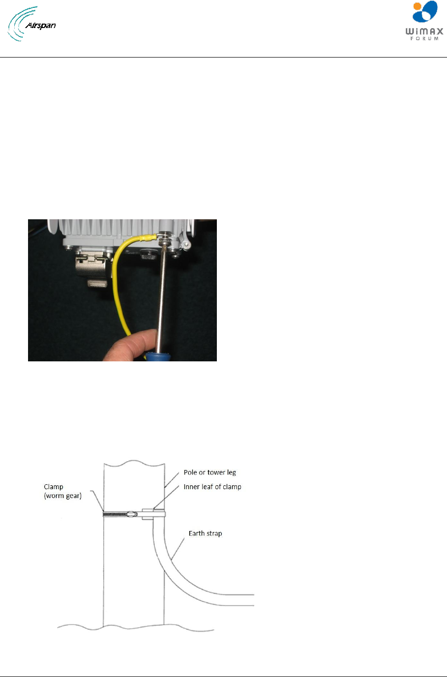
5.1.1 There is an option to connect an earthing cable to the M6 screw fixing point at the
bottom of the main body casting. This should be connected to a protection ground bar or
clamped directly to the steel structure of the power or pole. This is required in areas of high
lightning activity or when the AirSynergy unit is mounted on high exposed roofs or tower
structures. A direct earth connection is required for the surge protection devices inside the
AirSynergy to be effective.
Figure 31– AirSynergy attachment of earthing cable
5.1.2 Connect the earth cable to the protection earth bar using suitable crimp lugs.
Alternatively use a clamp to join the earth cable to the steel structure of the mounting pole or
tower structure.
Figure 32– Attach earth cable to pole
AirSynergy Equipment Installation Guide
Page 30 Commercial in Confidence SYN-UG-007 Rev A0.41
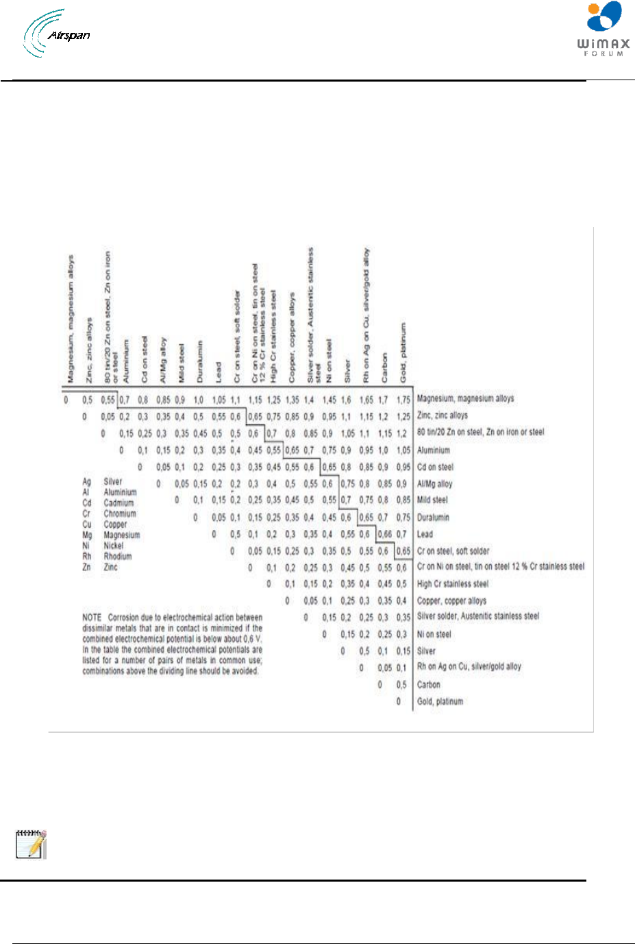
Note: When installing a protection earth take care to use suitable metal
combinations to avoid or minimize galvanic corrosion. Combinations above the
line in the table below should be avoided
AirSynergy Equipment Installation Guide
Page 31 Commercial in Confidence SYN-UG-007 Rev A0.41
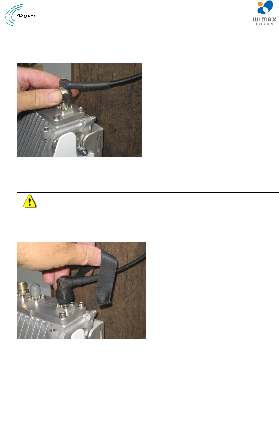
5.2 Connecting RF Jumper cables to External Antenna
Figure 33 – Connecting the antenna RF cables
Caution: Do not over-tighten the RF connector. RF failures can result when the
RF connector is over-tightened.
Weather-proofing of the RF N type connectors with weather-proofing tapes. (self -amalgamating
followed by a layer of black PVC tape.
Figure 34 – AirSynergy Front mount antenna connections – applying self -amalgamating tape
Apply a layer of self-amalgamating tape and a layer of black electrical tape to the weather-exposed
RF connector.
AirSynergy Equipment Installation Guide
Page 32 Commercial in Confidence SYN-UG-007 Rev A0.41
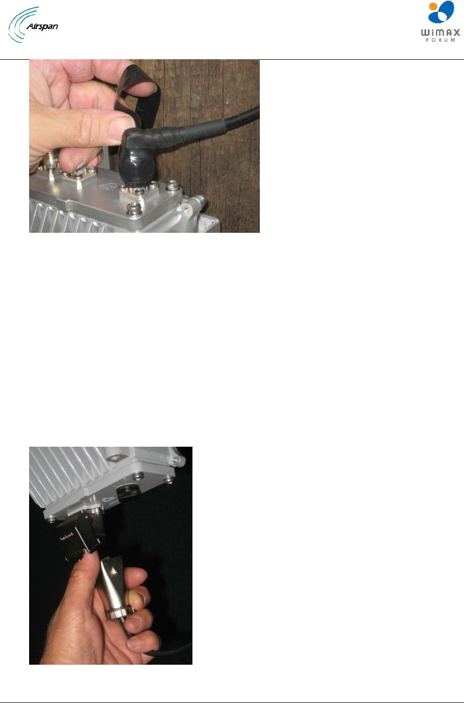
Figure 35 – AirSynergy antenna connections – applying PVC tape
Ensure the RF connector is completely sealed from the weather.
5.3 Connect PoE drop cable to the AirSynergy
5.3.1 Plan the position of the drop cable run from the AirSynergy unit to the PoE (Power over
Ethernet) injector. The recommended maximum run length is 20m. Uncoil the cable and secure with
the metal connector hood just below the AirSynergy unit. Pull back the hinged protective dust cover
and insert the PoE connector so that the RJ45 connector engages and the Amphenol hood locks into
place with the hinged dust cover. When securing the cable, make sure that there is no tension on the
connector so that it is easy to disconnect and re-connect for maintenance activities in the future. Take
care not to displace the square section sealing grommet from its channel at the end of the connector
since this is a vital to provide adequate water sealing.
Figure 36 – Attach PoE drop cable to the AirSynergy
AirSynergy Equipment Installation Guide
Page 33 Commercial in Confidence SYN-UG-007 Rev A0.41
6 Connect to Power System
Caution: Hazardous voltage! Before working, ensure that the power is removed
from the power connection cables. When the system is powered on, do not
touch the power terminals.
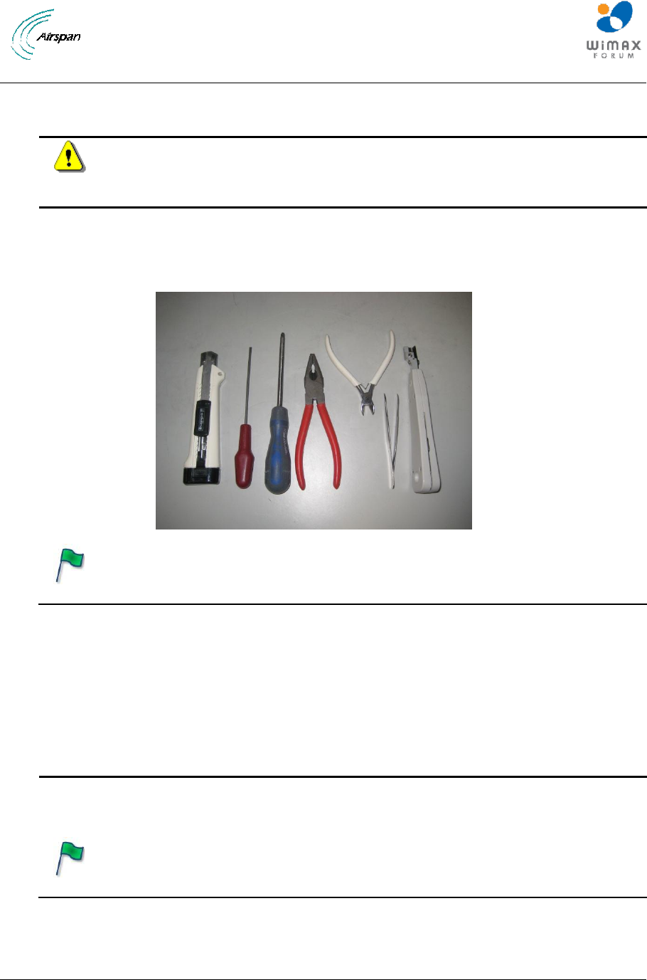
Tools Required: The tools required for the connection of the PSU and PoE
injector are: knife, small flat blade screw driver, medium cross-head screw driver,
pliers, small side cutters, tweezers (or fine blade long nose pliers) and punch
down tool (Krone or similar)
Figure 37 – Tools required to connect the PoE injector and PSU
6.1 Run cables from the PoE injector to the AirSynergy
6.1.1 The drop cable installation. If the drop cable is to be passed through glands and/or down the
centre of a lamp post or other structure, the drop cable can be cut leaving sufficient length for ease of
termination. (The cable length from the AirSynergy should be 20m max.) With the PoE injector
placed at the selected installation location, trim the cable length so that it will fit neatly to the box while
allowing sufficient length to strip and prepare the cable ends.
Note: It is good practice to label both ends of the drop cable to identify which
AirSynergy unit it is connected to. This is especially important where multiple
AirSynergy units are installed on the same pole/tower.

AirSynergy Equipment Installation Guide
Page 34 Commercial in Confidence SYN-UG-007 Rev A0.41
Note: It is good practice to leave a spare loop of drop cable (approximately 0.5m
of cable). This will allow for ease of wiring to the PoE and will allow the cable to
be re-terminated if necessary in the future.
6.1.2 The Network cable. The remaining section of cable with the RJ45 connector pre-fitted should
also be positioned to form the connection to a local network switch. (The length of this run should
be limited in length to 5m max.)
Note: It is good practice to leave a spare loop of network cable (approximately
0.5m of cable). This will allow for ease of wiring to the PoE and will allow the
cable to be re-terminated if necessary in the future.
6.1.3 If there is no planned Network connection at the installation site. It is recommended that a 1m
cable tail is connected to the PoE injector so that lap top computer or other test equipment can be
attached when required. When the installation is complete, the connector at the end of the tail should
be taped up with weather-proof tape and the wire neatly coiled and secured in a suitable space next
to the PoE injector. Add a label to identify which AirSynergy this network connection belongs to,
especially important where multiple AirSynergy units are installed on the same pole/tower.
Note: It is good practice to label the network connection cable to identify which
AirSynergy unit/PoE injector it is connected to. This is especially important where
multiple AirSynergy units are installed on the same pole/tower and the network
connection all converge on one Ethernet switch.
AirSynergy Equipment Installation Guide
Page 35 Commercial in Confidence SYN-UG-007 Rev A0.41
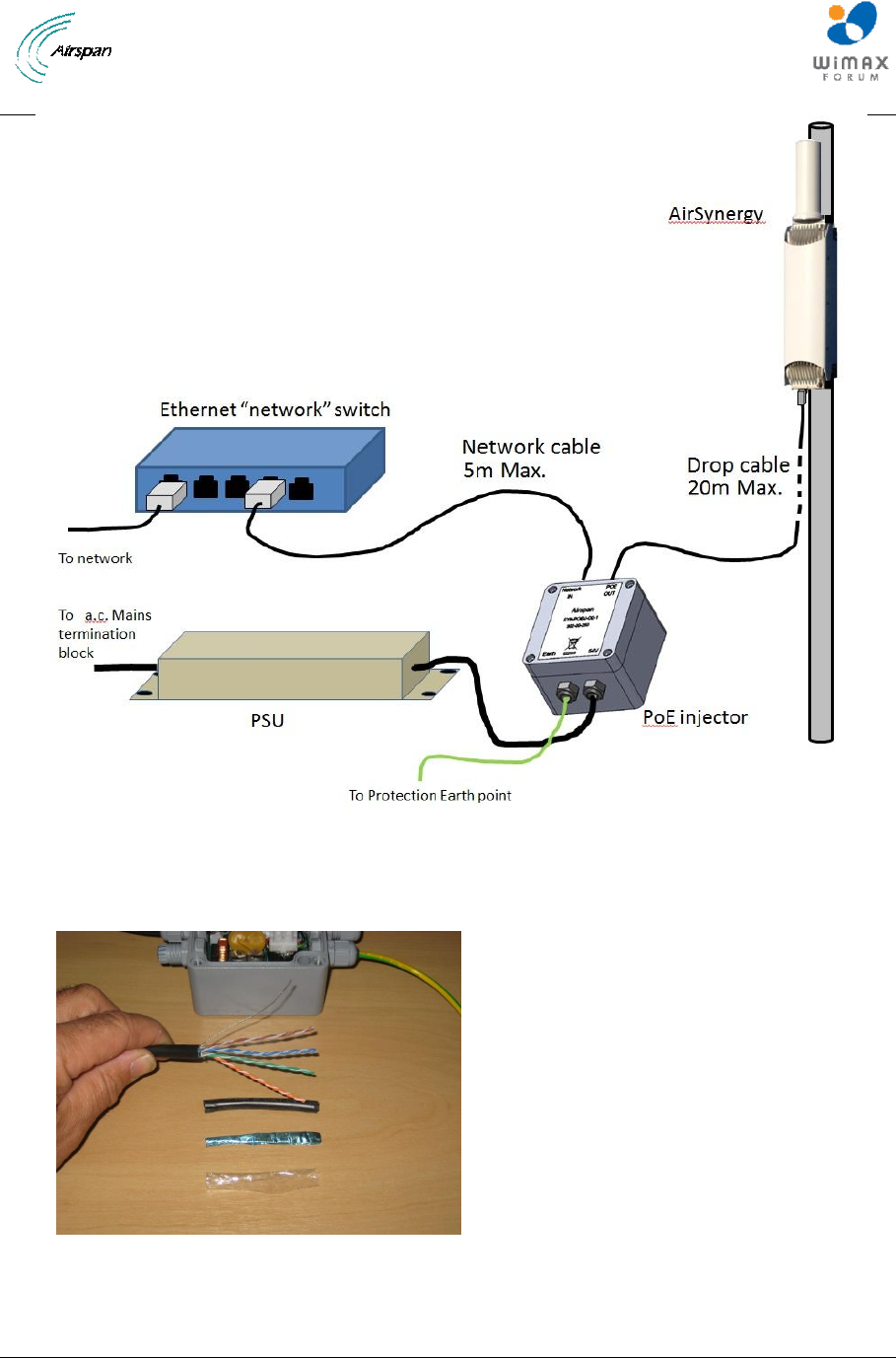
Figure 38 – AirSynergy power and network cable overview diagram
6.2 Wiring of the Drop cable and Network cables to the PoE injector
Figure 39 – Preparing the drop cable/network cable wire ends for connection into the PoE
injector
AirSynergy Equipment Installation Guide
Page 36 Commercial in Confidence SYN-UG-007 Rev A0.41
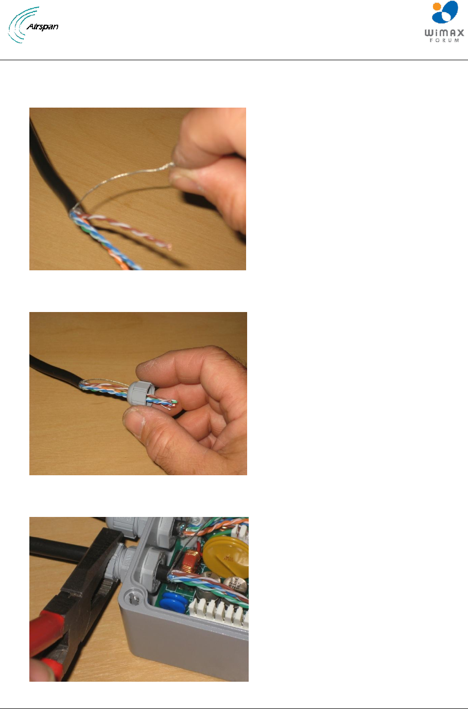
6.2.1 With the drop cable from the AirSynergy cut to the required length strip back and remove the
outer sheath, foil shield and wrapping layer to a length of 6cm. Take care not to cut the insulation on
the inner twisted pairs or any strands of the drain wire. Repeat for the network connection cable.
Figure 40 – Twist the individual drain wire strands together
Figure 41 – Pass the network cable /drop cable end through the end cap of a PoE gland
Figure 42 – Pass the cable through the gland and tighten the end cap
AirSynergy Equipment Installation Guide
Page 37 Commercial in Confidence SYN-UG-007 Rev A0.41
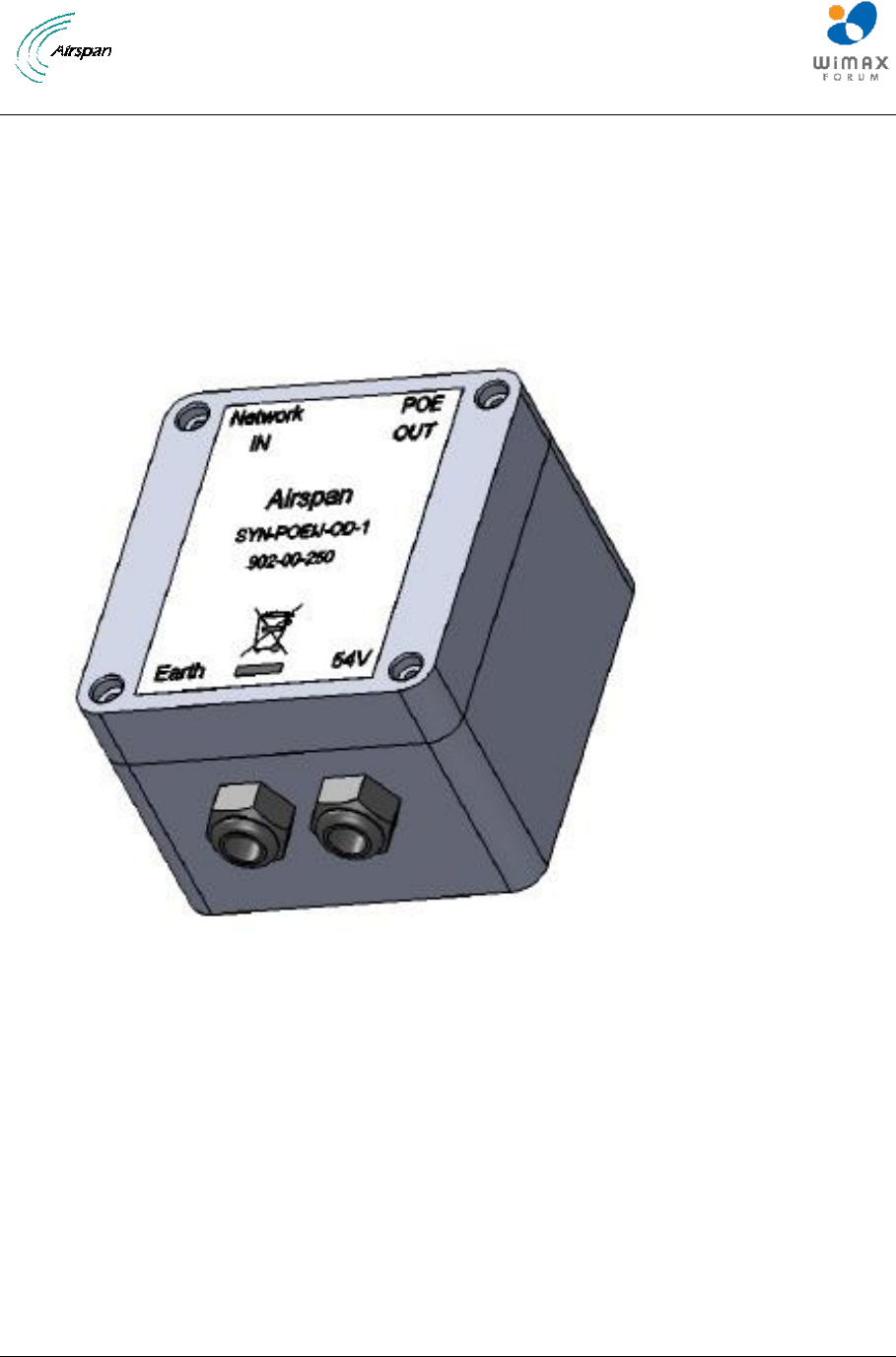
6.2.2 The drop cable and network cables must be passed through the correct cable glands in the
PoE until 5mm of black outer sheath protrudes into the box. Tighten the gland end caps securely with
pliers taking care not to over tighten or damage the plastic.
The drop cable from the AirSynergy enters through the gland labelled on the box lid as “POE OUT”
and the network connection enters through the gland labelled “Network IN”. The correct orientation of
the lid can be checked by lining up the pre-attached earth wire with the gland labelled “Earth”.
Figure 43 – View of the PoE injector lid indicating the 4 cable gland positions
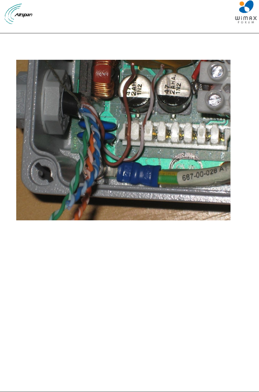
6.2.3 Preparing the twisted pairs for punch down. Untwist enough of each colour coded twisted pair
of wire so that the individual wires can be laid into the punch down strips. The colour code must be
strictly followed and is marked on the PCB legend next to each punch down “slot”. Gently pushing the
wires into the slots with a small flat blade screwdriver will help to keep them in the correct position
before they are punched down with the punch down tool. The wires must be positions so that the
“flying “ end is towards the centre of the PoE box.
AirSynergy Equipment Installation Guide
Page 38 Commercial in Confidence SYN-UG-007 Rev A0.41
Figure 44 – Position the individual pairs in the punch down strip
The wire installation order (starting from the end nearest to the entry gland) is:
BROWN
BROWN-WHITE
BLUE
BLUE-WHITE
GREEN
GREEN-WHITE
ORANGE
ORANGE-WHITE
AirSynergy Equipment Installation Guide
Page 39 Commercial in Confidence SYN-UG-007 Rev A0.41
Note: The Punchdown tool will only fit one way round with the cutter blades
towards the centre of the box
Figure 45 – The punch down orientation
Figure 46 – Continue dressing and punching down each coloured pair
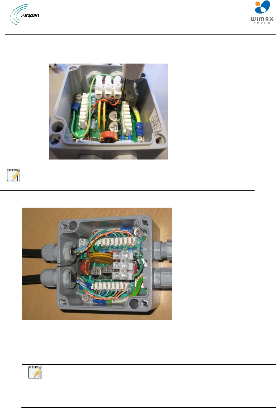
6.2.4 Continue dressing in and punching down the coloured pairs for the network and drop cables.
Take care to remove all cut-off wire ends from the box and trim off any ends that are not cleanly cut
by the punch down tool cutter.
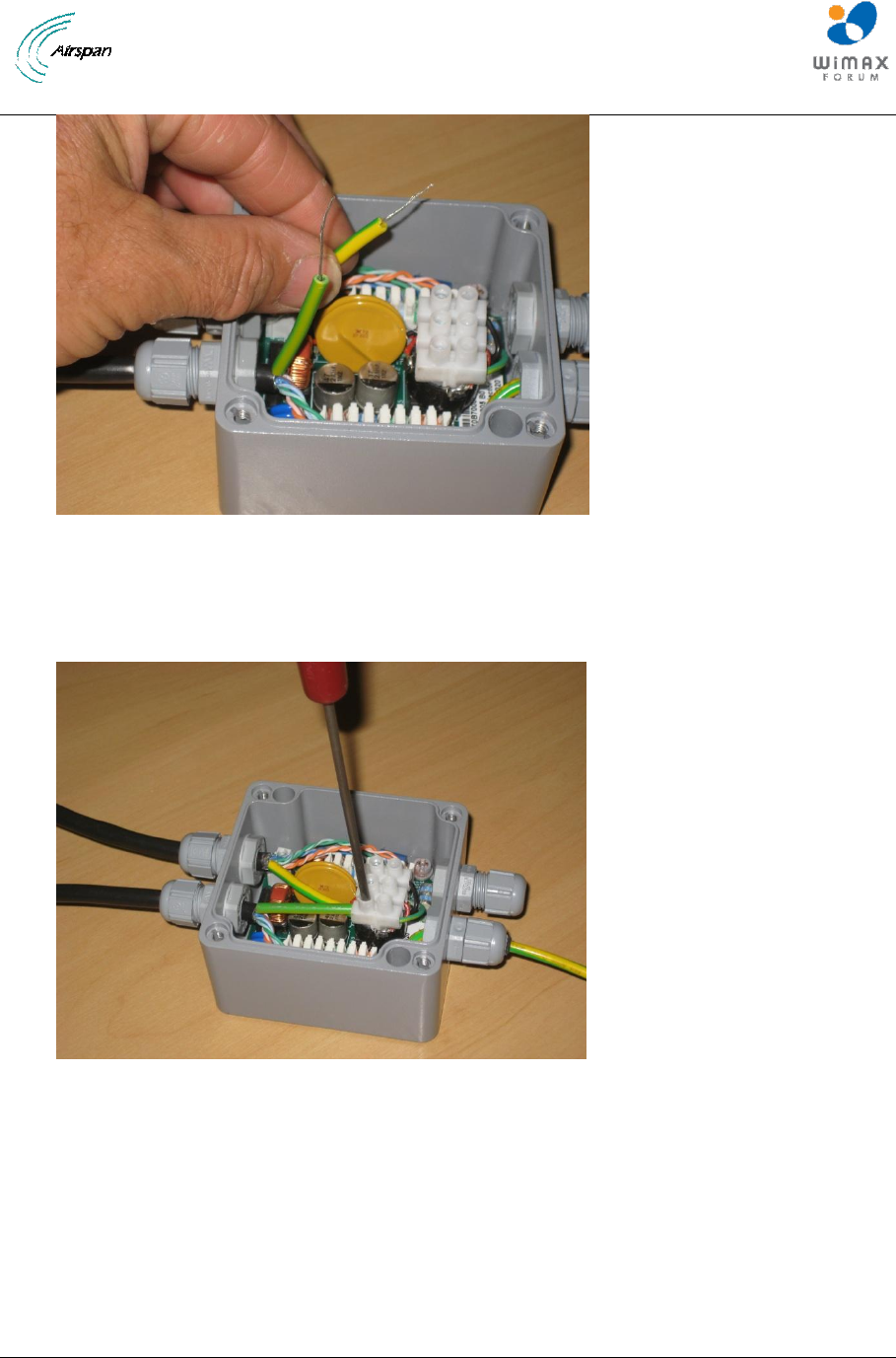
Note: : If the protection earth wire (green/yellow stripe) obstructs the punch down
tool, then slacken the earth wire gland and pull it through into the box so that a
small loop is formed that can be moved away from the punchdown block. When
the punchdown work is completed then restore the earth wire to its original
position and re-tighten the gland.
AirSynergy Equipment Installation Guide
Page 40 Commercial in Confidence SYN-UG-007 Rev A0.41
Figure 47 – Push green/yellow plastic sleeves over the drain wire
6.2.5 Fit pre-cut green/yellow plastic sleeves approximately 3.5cm long over each of the drain wires.
Figure 48 – Connect the drain wires to the earth terminal
6.2.6 Twist the bare ends of the drain wires together and insert into the 3 way terminal strip in line
with the pre-fitted green and yellow earth wire. Use a small blade screw driver to tighten the
connection.
AirSynergy Equipment Installation Guide
Page 41 Commercial in Confidence SYN-UG-007 Rev A0.41
6.3 Connecting the d.c. PSU
NOTE: For USA deployments and alternative PSU and enclosure arrangement
is required – Refer to Appendix E
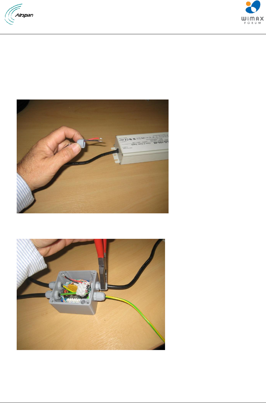
Figure 49 – Pass the d.c. power cable end through the end cap of a PoE gland
Figure 50 – Pass the d.c. power cable through the gland and tighten the end cap
6.3.1 The d.c. power cable (with red and black wire ends) must be passed through the correct cable
gland into the PoE until at least 5mm of black outer sheath protrudes into the box. Tighten the gland
end caps securely with pliers taking care not to over tighten or damage the plastic.
AirSynergy Equipment Installation Guide
Page 42 Commercial in Confidence SYN-UG-007 Rev A0.41
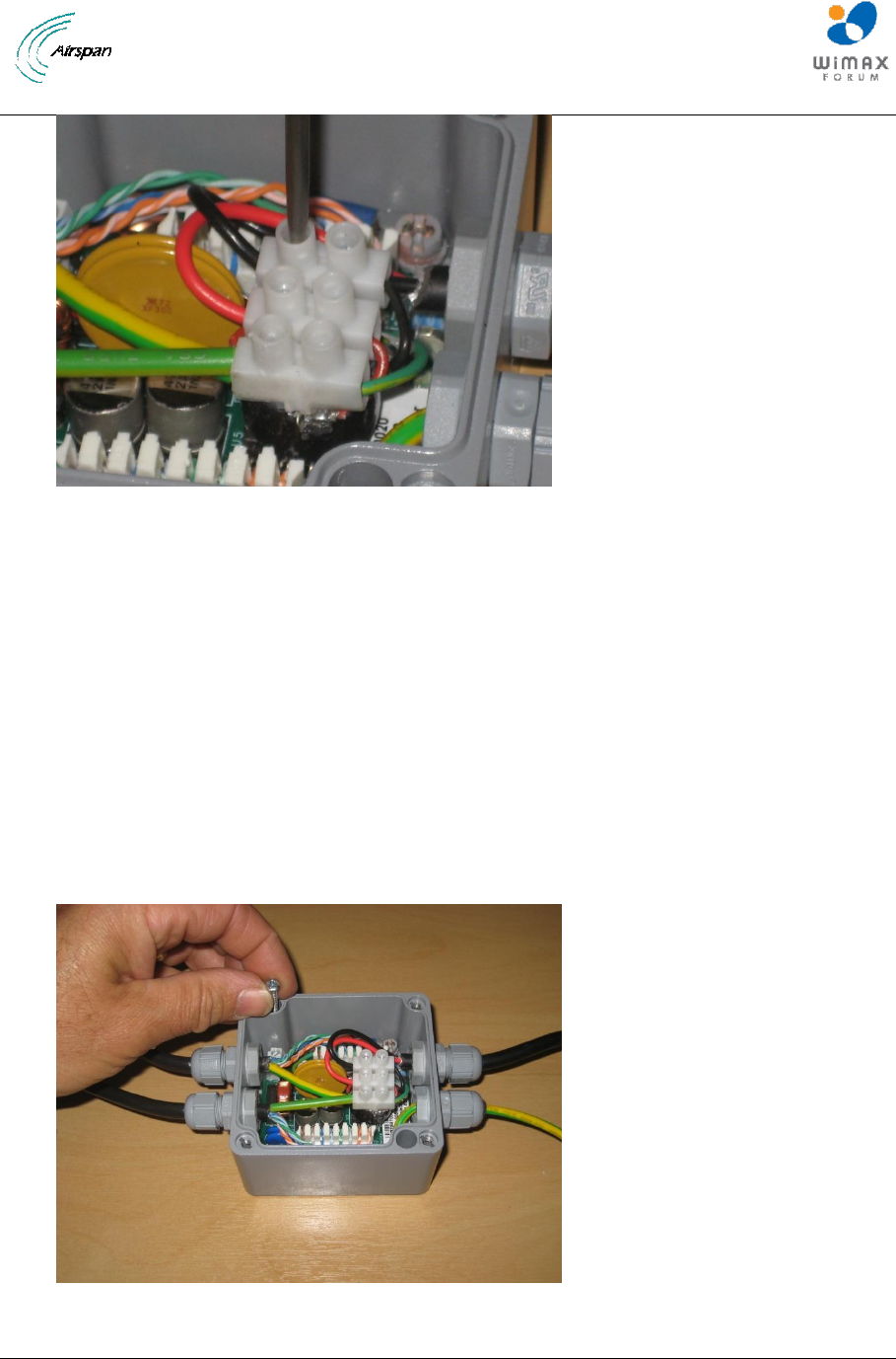
Figure 51 – Connect the red and black d.c. power wires into the terminal strip
6.3.2 Connect the red and black d.c. power wires to the correct positions in the 3-way terminal strip.
(In the positions where the colour line up with the pre-fitted red and black wires. Use a small blade
screw driver to tighten the connections. Re-check that all other screw terminals connections on the 3-
way terminal strip are tight.
6.4 Physical fixing of the PoE injector box and PSU modules
6.4.1 With the internal wiring complete the PoE box can be screwed into final position using the 2 self
tapping screws provided into a suitable wooden or insulated backing board. The fixing screws go into
the 2 holes within the body of the PoE injector box and must be fitted before assembling the top
cover.
Figure 52 – The wired PoE injector box can be screwed into position
AirSynergy Equipment Installation Guide
Page 43 Commercial in Confidence SYN-UG-007 Rev A0.41
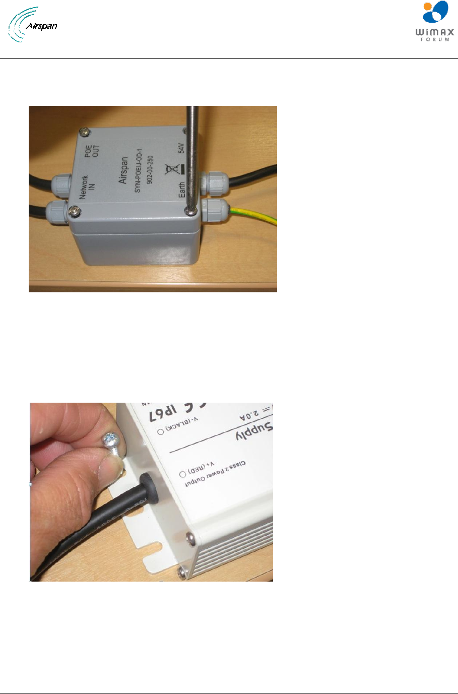
Figure 53 – Fit the top cover to the PoE injector box
6.4.2 Fit the top cover of the PoE injector box taking care to match the orientation of the label to the
assembled wiring.
Figure 54 – Fix the PSU into position using self tapping screws
6.4.3 The PSU module can be screwed into final position using the self-tapping screws provided into
a suitable wooden or insulated backing board (4 positions)

AirSynergy Equipment Installation Guide
Page 44 Commercial in Confidence SYN-UG-007 Rev A0.41
Safety - Disconnection of AC supply
Where Airsynergy is connected directly to building or lamp post wiring a suitably
rated and readily accessible disconnect device shall be incorporated external to the
equipment;
Where Airsynergy is connected to the ac mains supply using a plug and socket, the
socket-outlet shall be installed near the equipment and shall be easily accessible.
AirSynergy Equipment Installation Guide
Page 45 Commercial in Confidence SYN-UG-007 Rev A0.41
7 Set BS Management IP & BSID via Web Page
The following are the steps to the BS via its WEB interface.
Ensure that your Web browser with which you want to access the Web-based Management is active.
To connect to AirSynergy via the WEB interface:
1. Open web browser ant type the BS address.
IP address – 192.168.0.100 (255.255.255.0)
User name – synergy
Password – synergy
2. Click Submit
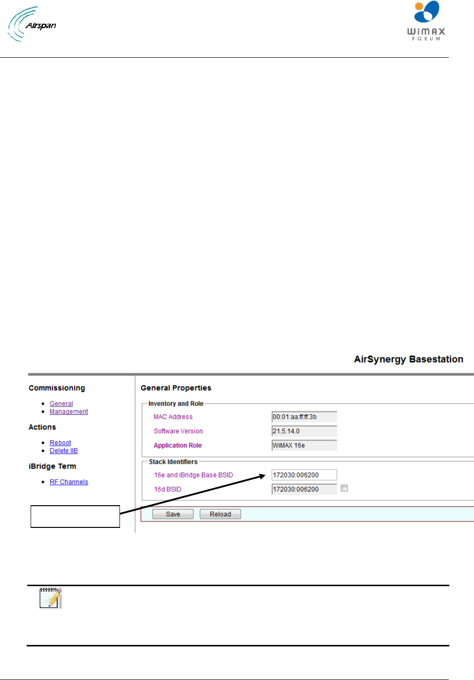
3. For WiMAX 16e applications Navigate to “General” menu to specify the BS ID. (Format
xxxxxx:yyyyyy)
Where xxxxxx is reserved for the Operator ID and yyyyyy is a unique Hexadecimal reference
number within the network. The commissioning details vary for iBridge and LTE applications and
these are covered in separate commission documents
Figure 55- BS Config
4. Click Save.
Note: iBridge Term menu item is not applicable to 16e BS and must not be
used. Configuration of “RF Channels” may lead to failed installation (failed
commissioning and no discovery). Configuartion details for iBridge is covered in
a separate document
Write the BS ID
AirSynergy Equipment Installation Guide
Page 46 Commercial in Confidence SYN-UG-007 Rev A0.41
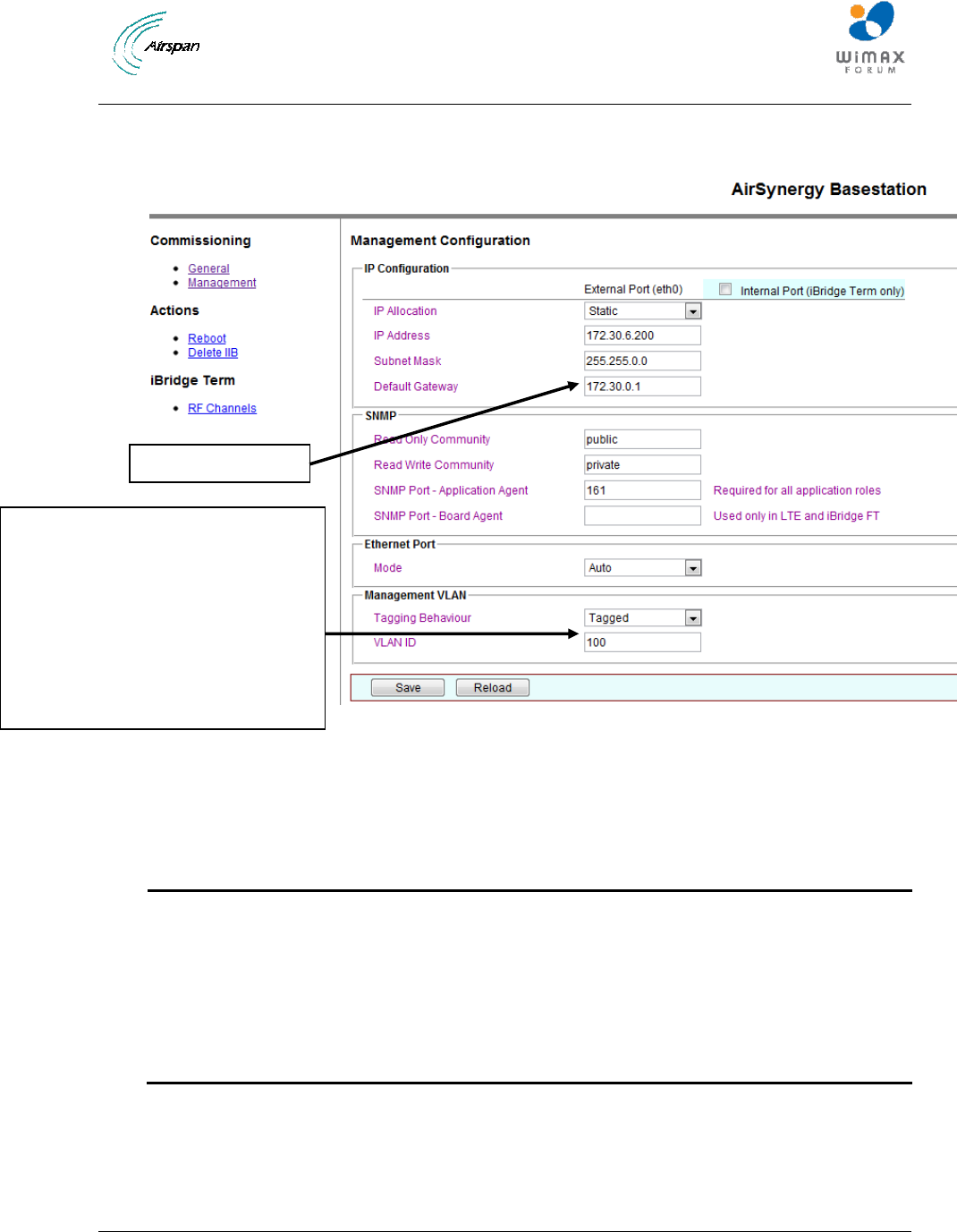
5. Navigate to “Management” and modify the IP address according to your network.
Figure 56- Mgmt IP Config
6. Click Submit
Note: Dynamic” IP Allocation is not supported in the current release. Please
select Static
Note: Internal Port configuration is not applicable to 16e BS and must not be
used. Configuration of the internal port may lead to management comms failure.
Note: Clicking the “Submit” your configuration is NOT implemented immediately
in the BS. The BS needs to be rebooted for the new configuration to be applied.
Choose Untagged or Modify the BS
Management VLAN when applicable
(Take care when changing to a
management VLAN since
communication from a Laptop or PC
without the relevant 802.1Q NIC
capability and configuration will be
lost)
Modify the BS IP
IPIP
AirSynergy Equipment Installation Guide
Page 47 Commercial in Confidence SYN-UG-007 Rev A0.41
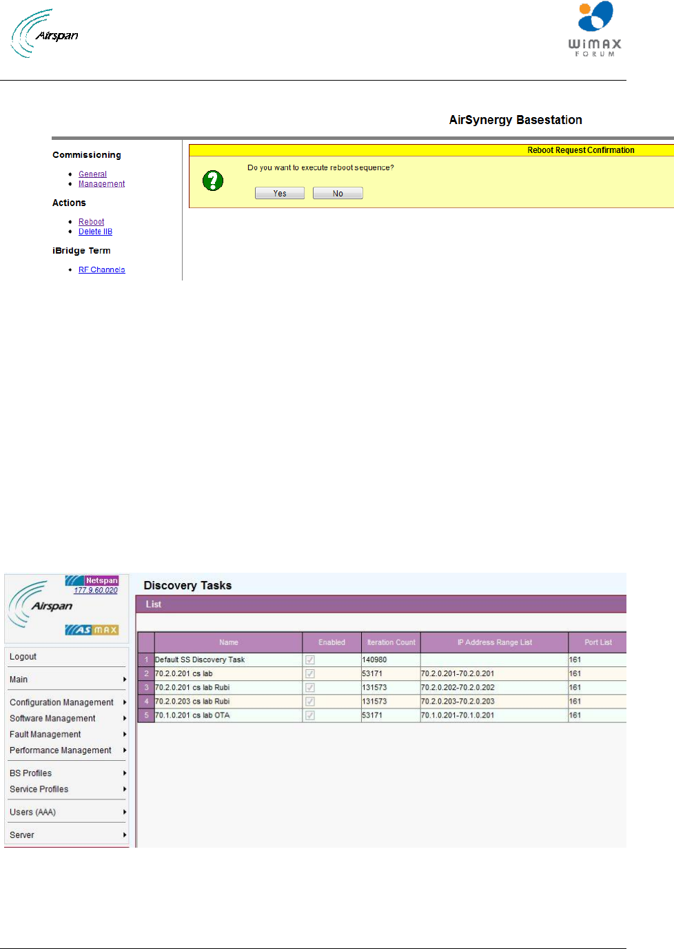
7. Navigate to “Reboot” and click on “Yes” to reboot the BS
Figure 57- Reboot Confirmation
7.1 Automatic Discovery via Netspan
Set BS discovery profile in Netspan.
The following section explains the steps to take for the automatic discovery of AirSynergy via
Netspan.
To connect to AirSynergy BS via Netspan
1. Login to Netspan
2. Navigate to Server > Discovery Parameters
The following is displayed:
Figure 58- Discovery Tasks
3. Click Add
AirSynergy Equipment Installation Guide
Page 48 Commercial in Confidence SYN-UG-007 Rev A0.41
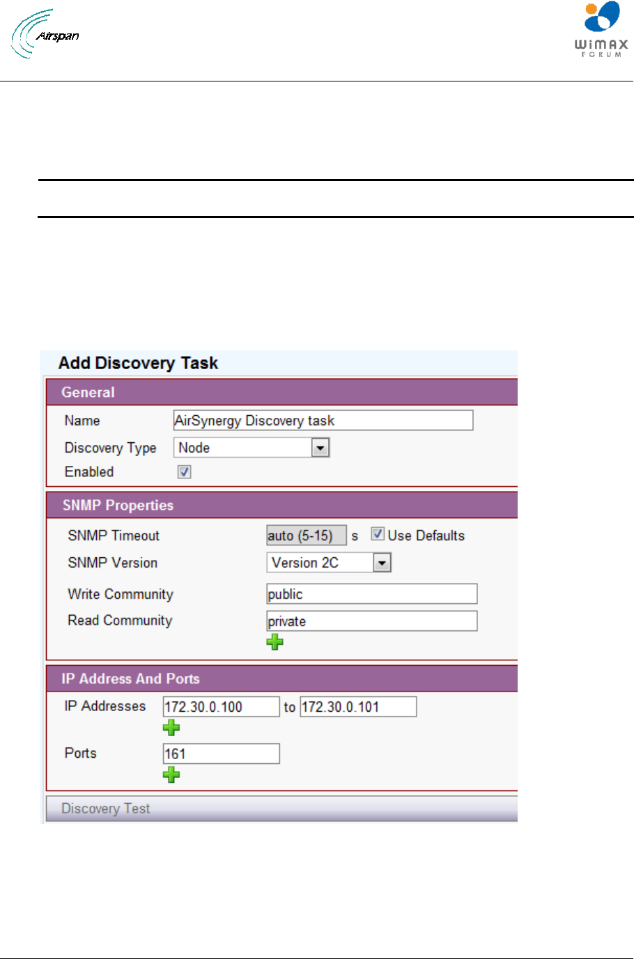
4. Define:
a. Name.
b. Write Community.
c. Read Community
Note: This should be same as was configured before on the BS.
5. Define the discovery Target IP Address Range. For example – Start address = 172.30.0.100
and End Address=172.30.0.101
6. Port – enter 161
7. Click OK, as shown below:
8.
Figure 59- Edit Discovery tasks parameters
9. Click OK and wait till you see the new BS in the “ configuration management > BS > BS TRx,
as shown below:
AirSynergy Equipment Installation Guide
Page 49 Commercial in Confidence SYN-UG-007 Rev A0.41
Figure 60 - Discovery Target
Your AirSynergy BS is now “discovered” by Netspan and is ready for additional configuration,
provisioning and adaptations.
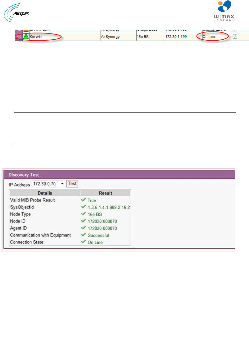
Note: In case of discovery failure (BS not present on the list) Discovery Test can
be used to diagnose the problem. Select Discovery Task created and Click Edit.
Select the discovery parameters and press Test. The report appears. Correct the
problem and try again.
Figure 61 - Discovery Test

AirSynergy Equipment Installation Guide
Page 50 Commercial in Confidence SYN-UG-007 Rev A0.41
8 Appendix A
8.1 Review Job Sheet
The Job Sheet should include the following information:
Pole for installation identified
Position on pole identified
Pole access restrictions (highway regulations, other services on pole, power pole)
Method of reaching pole positions (ladders, Elevated work platform)
AC main fuseway available for PSU
Configuration programming details known
Point of connection for Ethernet (if applicable)
All equipment items available at the installation site
o Main AirSynergy unit
o Mounting bracket and pole clamps
o PSU
o PoE injector (with fixing kit)
o Ethernet cable assembly
o GPS Antenna
o GPS antenna installation kit
o Front sector Antenna (if applicable)
o Front sector Antenna mounting bracket ad fixing kit (if applicable)
o External panel antenna (if applicable)
o RF feeder cable tails (if applicable)
Required tools
o Large flat screw driver for pole clamps
o Small flat screwdriver for PoE power terminations
o Small cross-head screwdriver for PoE box lid and fixings for PoE injector and
PSU
o 20mm wrench or small pipe wrench for RF connections
o 10mm wrench for main unit mounting flange nuts
o Side cutters
o Wire strippers
o Krone punch down tool
o Tilt meter to set antenna downtilts
o Ring terminals crimp tool
Required ancilliary equipment
o Lap top PC for initial configuration
o Ethernet cable for temporary connection of the lap top
Other install materials
o Self amalgamating
o Black PVC tape
o Cable ties
o Labels

AirSynergy Equipment Installation Guide
Page 51 Commercial in Confidence SYN-UG-007 Rev A0.41
Whether the system is required to be locked to a GPS timing reference.
A BSID is required for each AirSynergy. This should be in a format xxxxxx:xxxxxx where x
is a decimal digit.
Network configuration information for the SDR blade. This shall include the following
information for the front panel and the backplane.
o IP Address: Should only be set if Management IP Mode is set to Static IP Address.
See below for Management IP Mode parameter.
o Netmask: Should only be set if Management IP Mode is set to Static IP Address.
See below for Management IP Mode parameter.
o Default Gateway: Should only be set if Management IP Mode is set to Static IP
Address. See below for Management IP Mode parameter.
o Management VLAN: Specified as either Untagged or Tagged
o Management VLAN Tag: Should only be set if Management VLAN is set to Tagged
o Management IP Mode: Specified as Static IP Address or Obtain IP Address via
DHCP
o Ethernet Mode: Specified as Auto-negotiate or Fixed
o Ethernet Rate: Need only be configured if Ethernet Mode is set to Fixed, specified
as 10M or 100M.
o Ethernet Duplex: Need only be configured if Ethernet Mode is set to Fixed,
specified as Full or Half.
SNMP configuration information. This will allow events from the BS to arrive at the
specified Netspan server. This will include the following information:
o Read Only Community: This should be specified to the same value as in Netspan
Discovery Parameters (found under Server on Netspan’s left hand panel).
o Read Write Community: This should be specified to the same value as in Netspan
Discovery Parameters (found under "Server" on Netspan’s left hand panel).
o Community: Normally specified to the same value as for Read Only Community.
AirSynergy Equipment Installation Guide
Page 52 Commercial in Confidence SYN-UG-007 Rev A0.41
9 Appendix B – Field assembly of Back to back AirSynergy units
In cases where 2 AirSynergy radios are to be installed on the same mounting bracket some additional
installation steps are required as follows:
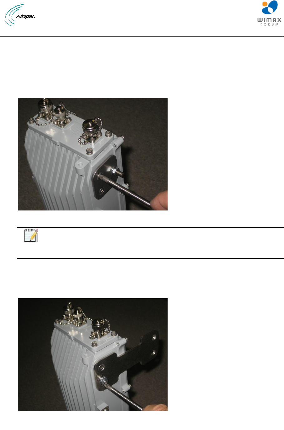
Removal of the existing stud mounting plates (4 positions) from each AirSynergy unit. Each plate is
secured with 2 countersunk head screws.
Figure 62 - Removing the existing stud mounting plates
Note: The screws should be replaced with a new set of 16 pieces with fresh
locking patches on the threads when re-assembling with the joining plates. A new
set of screws is supplied with the back to back joining kit.
Re-assembly with the joining plates. The studs with flange nuts must all be at the same end. A typical
arrangement will be with the AirSynergy with connectorised RF ports to be mounted at the back. The
mounting studs will then all be on the sides of the connectorised unit as shown in the figure. Fit all 4
plates to one of the AirSynergy units then slide the 2nd Synergy unit into place between the brackets.
Figure 63 - Fitting the stud joining plates
AirSynergy Equipment Installation Guide
Page 53 Commercial in Confidence SYN-UG-007 Rev A0.41
Figure 64 - Position back to back assembly on side to tighten all joining plate screws
Note: To fully tighten all of the screws it is recommended to place the cardboard
packaging or other soft material under the units to protect the painted surfaces
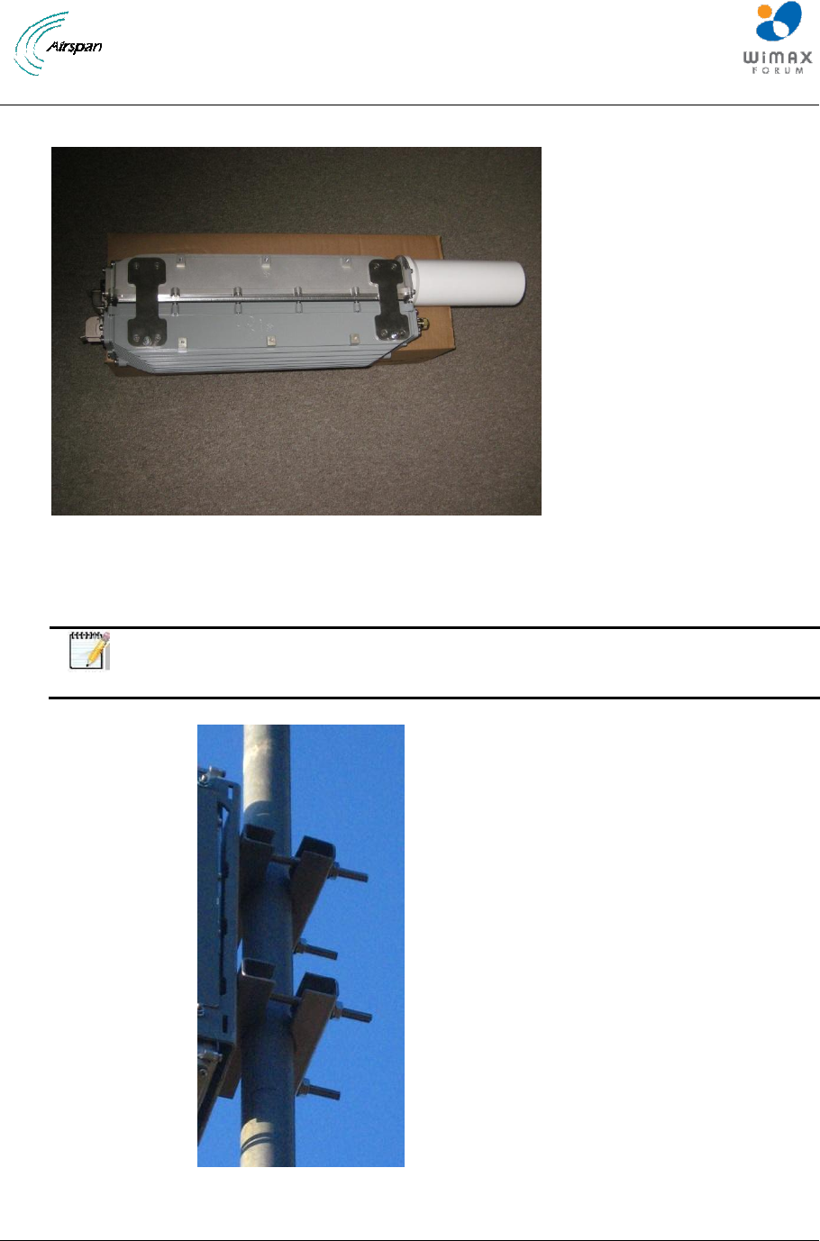
Figure 65 - Mounting method with pole clamps recommended for back to back
installations
AirSynergy Equipment Installation Guide
Page 54 Commercial in Confidence SYN-UG-007 Rev A0.41
Note: To support the additional weight of a back to back system on a single
universal mounting plate it is recommended that a pole clamp kit is used (see
figure 58) This provides a very strong mounting from a standard telecom tower
equipment pole. For larger diameter poles where pole straps are required due to
the larger diameter of the pole, it is recommended that 4 straps are used. It is
important that pole straps sit flat against the mounting plate as shown in figure 59
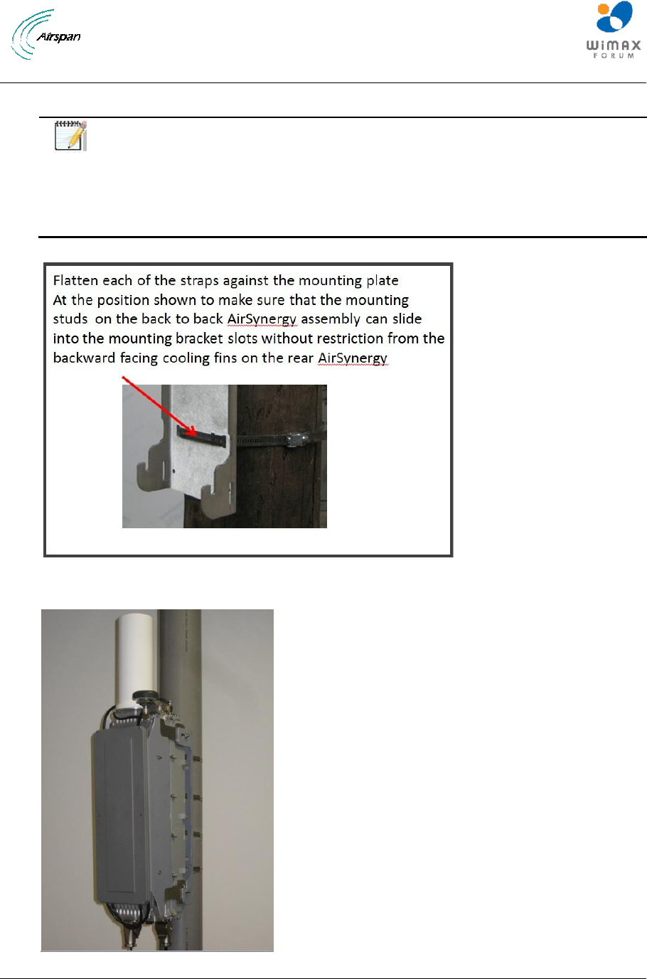
Figure 66 - Flatten straps against the mounting plate for back to back installations
Figure 67 - Back to Back AirSynergy mounted on pole with 4 mounting straps
AirSynergy Equipment Installation Guide
Page 55 Commercial in Confidence SYN-UG-007 Rev A0.41
Mount the assembly on the universal mounting bracket and secure the flange nuts. The GPS antenna
and front mount antenna if used can be fitted before or after mounting to the pole depending on ease
of access.
In cases where no front mount antenna is fitted, an extended sun shield is available as an accessory
item and should be fitted. The fitting method is the same as the standard sun shield with 3 fixings on
each side of the front AirSynergy unit.
Follow the normal procedures for the connection of power supply units and drop cabling to each of the
back to back mounted AirSynergy units.
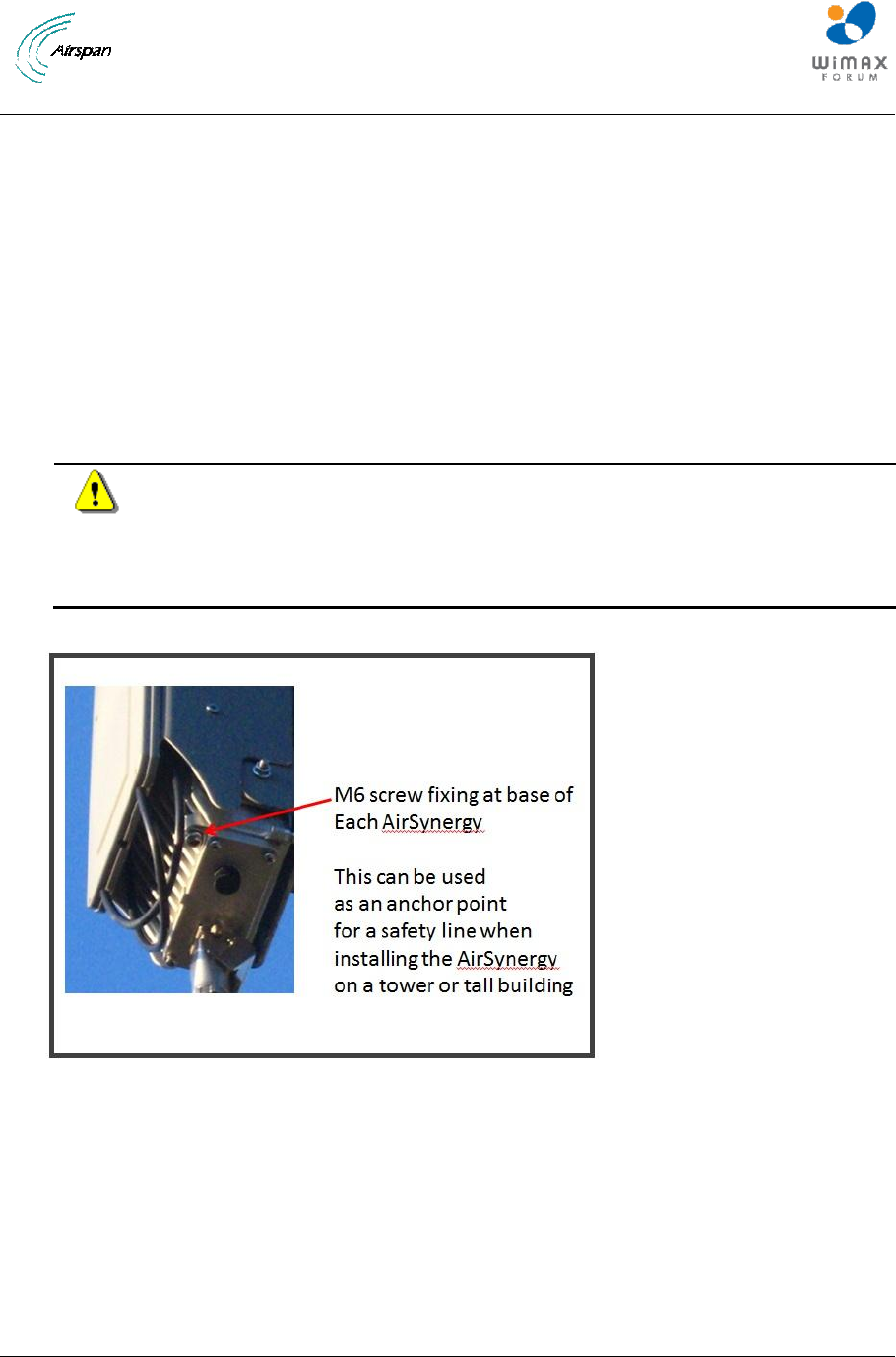
Note: When securing back to back assembly to the mounting plate a safety line or
rope should be secured to the units. The 6mm tapped holes used for the
protection ground at the bottom or the GPS mountings at the top of each Synergy
unit provide strong anchor points for a safety line. (This is the same point used
for protection ground connection in exposed areas or high lightening risk areas)
Figure 68 – M6 Screw fixing point as safety line anchor point

AirSynergy Equipment Installation Guide
Page 56 Commercial in Confidence SYN-UG-007 Rev A0.41
10 Appendix C – Glossary of Terms
AAA
Authentication, Authorization and Accounting
ARQ
Automatic Repeat Request
ASN
Access Service Network
ASN GW
ASN Gateway
BS
Base Station
BWA
Broadband Wireless Access
CPE
Customer Premises Equipment
FDD
Frequency Division Duplex
GUI
Graphical User Interface
HO
Handover/Handoff
IP
Internet Protocol
NEMA
MAC
National Electrical Manufacturers Association
Media Access Control
MIMO
Multiple Input Multiple Output
MS
Mobile Station
NLOS
Non Line of Sight
NSP
Network Service Provider
OFDMA
Orthogonal Frequency Division Multiplexing (Multiple Access)
PHY
PHYsical Layer
SDR
Software Defined Radio
TDD
Time Division Duplex
VoIP
Voice over IP

AirSynergy Equipment Installation Guide
Page 57 Commercial in Confidence SYN-UG-007 Rev A0.41
11 Appendix D – Checklist
The Checklist below gives the high-level steps in the Workflow for this procedure. Detach or print this
page to use as a job-aid for completing the actions this procedure requires.
Table 3 - Checklist for Procedure
Procedure
Actions
Outcome
1. Verify Prerequisites
Verify site requirements
Verify safety
requirements
Verify installation
requirements
All requirements are in
place for a successful
installation
2. Install AirSynergy
universal mounting plate
Install the universal
mounting plate
Verify connection torque
settings
3. Install AirSynergy on
the mounting plate
4. Connect and manage
cables
Connect AirSynergy PoE
cable
Connect GPS
5. Connect power system
Connect PSU to PoE
injector
Connect Power
Connect the protection
earth to the PoE injector
box
Connect Ethernet
backhaul
AirSynergy Equipment Installation Guide
Page 58 Commercial in Confidence SYN-UG-007 Rev A0.41
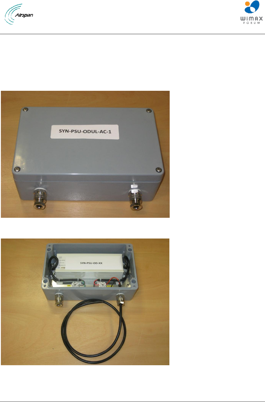
12 Appendix E – PSU for USA
To comply with US regulations that apply to outdoor deployments of mains power supplies, a special
US version of the AirSynergy power supply has been produced with the PSU module and the mains
connecting blocks enclosed in a small NEMA approved enclosure. The mains cable and 48V power
cables are brought through the weatherproof glands provided. This type of power supply (SYN-PSU-
ODUL-AC-1) must be used for all deployments in the USA.
Figure 69 – AirSynergy Mains PSU and enclosure for USA deployments
Figure 70 – 48V DC cable attached ready for connection to the PoE injector
AirSynergy Equipment Installation Guide
Page 59 Commercial in Confidence SYN-UG-007 Rev A0.41
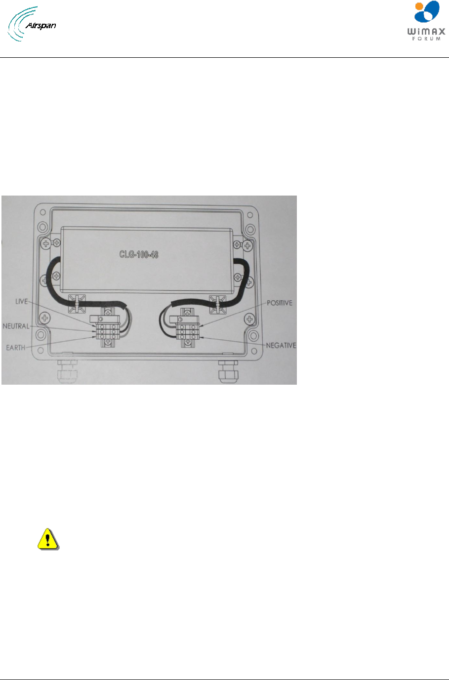
Remove the top cover of the PSU enclosure. Choose suitable positions for the PSU enclosure within
1m of the PoE injector. The PSU enclosure should be screwed to a firm surface with screws in 4
positions which are only accessible with the top cover removed.
A 1metre length of 2 core connecting cable should come pre-attached to the 48V output terminals as
shown in Figure 68. This cable may be cut to shorter length, depending on the position of the PoE
injector. Terminated the DC cable in the PoE injector as described in section 6.3.1
Figure 71 – Internal PSU and and cable terminations
Isolate the mains supply and pass the mains cable through the input gland and terminate on the
connection blocks provided. The termination blocks are clearly labelled as Live, Neutral and Earth.
Once the enclosure top cover has been re-fitted (4 screw positions) and the PoE wiring completed the
mains power can be applied.
Safety - Disconnection of AC supply
Where Airsynergy is connected directly to building wiring a suitably rated
and readily accessible disconnect device shall be incorporated external to the
equipment;
Where Airsynergy is connected to the ac mains supply using a plug and socket, the
socket-outlet shall be installed near the equipment and shall be easily accessible.

AirSynergy Equipment Installation Guide
Page 60 Commercial in Confidence SYN-UG-007 Rev A0.41
13 Appendix F – FCC Requirements
Airsynergy basestation, FCC ID: O2J-235AS, operating in the
2305-2320 and 2345-2360 MHz WCS Bands.
Federal Communications Rules for operation in USA
The correct setting of the following Base Station parameters in Netspan, are critical to
the correct operation of equipment in compliance with the rules detailed in 47CFR27subpart
C:
Transmit Power
Transmit Frequency
Channel Bandwidth
Any attempt to alter these parameters outside those permitted by the Netspan software or the
operator license could be a violation of that license
Transmit Power / Tune-up
Transmit power is set using the Netspan management software during install /commissioning.
The unit may transmit with a power of up to 30dBm at each antenna port when connected to
cross polarised antenna with maximum gain of 18dBi
Airsynergy basestation, FCC ID: O2J-265AS, operating in the
2572-2614 MHz band.
Federal Communications Rules for operation in USA
The correct setting of the following Base Station parameters in Netspan, are critical to
the correct operation of equipment in compliance with the rules detailed in 47CFR27subpart
C:
Transmit Power
Transmit Frequency
Channel Bandwidth
Any attempt to alter these parameters outside those permitted by the Netspan software or the
operator license could be a violation of that license
Transmit Power / Tune-up
Transmit power is set using the Netspan management software during install /commissioning.

AirSynergy Equipment Installation Guide
Page 61 Commercial in Confidence SYN-UG-007 Rev A0.41
The unit may transmit with a power of up to 30dBm at each antenna port when connected to
cross polarised antenna with maximum gain of 18dBi
Airsynergy Basestation, FCC ID: O2J-365AS, operating in the
3650-3700 MHz Band.
Federal Communications Rules for operation in USA
To ensure compliance FCC rules and regulations, the following should be observed:
The 3650-3700 MHz frequency range is a licensed band in the USA and operators
must have a valid spectrum license to operate Airsynergy equipment using this band.
The Airsynergy base station requires operation using an Airspan FCC-specific version
of Netspan supporting Listen Before Transmit. This management software only
permits operation in the 3650-3700 MHz band.
Note: Netspan, the Airspan management system enforces FCC compliance in the upper
25MHz extension of this band above 3675 MHz
The unit and must be professionally installed.
Any attempt to alter these parameters outside those permitted by the Netspan software
or the operator license could be a violation of that license
The correct setting of the following Base Station parameters in Netspan, are
critical to the correct operation of equipment in compliance with the rules detailed in
47CFR90 subpart Z (Wireless Broadband Services in the 3650–3700 MHz Band):
o Transmit Power
o Transmit Frequency
o Channel Bandwidth
o Carrier Sense Threshold
o Carrier Sense Backoff Frames
Transmit Power
Transmit power is set using the Netspan management software during install /commissioning.
For 5MHz channel operation, the maximum permitted EIRP is 5 W. Due to the additive
effect of the MIMO antenna, the power setting in Netspan must be set such that:
TX power (dBm) + Antenna gain (dBi) ≤ 36.5
For 10 MHz channel operation, the maximum permitted EIRP is 10 W. Due to the additive
effect of the MIMO antenna, the power setting in Netspan must be set such that:

AirSynergy Equipment Installation Guide
Page 62 Commercial in Confidence SYN-UG-007 Rev A0.41
TX power (dBm) + Antenna gain (dBi) ≤ 39.5
Airsynergy Basestation, IC:4548B - 90203300, operating in the
3650-3700 MHz Band.
Industry Canada Rules for operation in Canada
To ensure compliance with relevant rules and regulations, the following should be observed:
The 3650-3700 MHz frequency range is a licensed band in Canada and operators
must have a valid spectrum license to operate Airsynergy equipment using this band.
The Airsynergy base station requires operation using an Airspan FCC-specific version
of Netspan supporting Listen Before Transmit
1
. This management software only
permits operation in the 3650-3700 MHz band.
Note: Netspan, the Airspan management system enforces FCC compliance in the upper
25MHz extension of this band above 3675 MHz
The unit must be professionally installed.
Any attempt to alter these parameters outside those permitted by the Netspan software
or the operator license could be a violation of that license
The correct setting of the following Base Station parameters in Netspan, are
critical to the correct operation of equipment in compliance with the rules detailed in
RSS-197 (Wireless Broadband Access Equipment Operating in the 3650–3700 MHz
Band):
o Transmit Power
o Transmit Frequency
o Channel Bandwidth
o Carrier Sense Threshold
o Carrier Sense Backoff Frames
Transmit Power
Transmit power is set using the Netspan management software during install /commissioning.
The Maximum permitted total power density allowed in RSS-197 is 1W/MHz
Certification testing was performed with an antenna gain of 11dBi and the following transmit
powers in Netspan software and these must not be exceeded during commissioning or use:
5 MHz channels: 23.5dBm
10 MHz Channels: 25.5 dBm
1
This software version is generically called the “Airspan FCC-specific version” as the software was
historically written to comply with 47CFR90Z which imposes a similar Contention Based Protocol
Requirement

AirSynergy Equipment Installation Guide
Page 63 Commercial in Confidence SYN-UG-007 Rev A0.41
RF Exposure
The RF exposure requirements are detailed in RSS-210.
The safe distances from the AirSynergy Antenna unit is 25 cm under all operating
conditions.
FCC and Industry Canada RF Exposure Requirements
FCC Maximum Permissible Exposure (MPE) limits for equipment operating in the
frequency range 1500 – 100,000 MHz is 1.0 mW/cm2.
Following installation and commissioning, the safe distance from the antenna is the
greater of:
20cm
Or
r cm, where r = √ (PG/4πS)
P: power input to antenna(s) in mW
G: numeric gain of antenna relative to isotropic radiator
S: power density in mW/cm2 = 1 mW/cm2
The device has two antenna ports, so safe distance from the antenna shall be the greater
of:
20 cm or √ (2*PG/4πS)
Which gives
20 cm or √ (0.16*P*G) cm.

AirSynergy Equipment Installation Guide
Page 64 Commercial in Confidence SYN-UG-007 Rev A0.41
14 Appendix G – Declaration of Conformance (CE) for Airsynergy
Following European guidance to include the Decalaration of Conformance into the user
manual, the Declaration of Conformance for AirSynergy is included here in the 11 languages
of the Community relating to the 2.3GHz and 3.6GHz variants of the AirSynergy product.
These equipments must only be operated under licence
Note: A copy of full declaration of conformity may be obtained from Airspan Communication
Ltd, Capital Point, 33 Bath Road, Slough Berkshire SL1 3UF UK
English
Hereby, Airspan Communications Ltd., declares that this AirSynergy (2.3 and
3.6GHz variants) is in compliance with the essential requirements and other
relevant provisions of Directive 1999/5/EC.
Finnish
Airspan Communications Ltd. vakuuttaa täten että AirSynergy (2.3 and
3.6GHz) tyyppinen laite on direktiivin 1999/5/EY oleellisten vaatimusten ja sitä
koskevien direktiivin muiden ehtojen mukainen.
Dutch
Hierbij verklaart Airspan Communications Ltd. dat het toestel AirSynergy (2.3
and 3.6GHz) in overeenstemming is met de essentiële eisen en de andere
relevante bepalingen van richtlijn 1999/5/EG
Bij deze verklaart Airspan Communications Ltd. dat deze AirSynergy (2.3 and
3.6GHz) voldoet aan de essentiële eisen en aan de overige relevante
bepalingen van Richtlijn 1999/5/EC.
French
Par la présente Airspan Communications Ltd. déclare que l'appareil
AirSynergy (2.3 and 3.6GHz) est conforme aux exigences essentielles et aux
autres dispositions pertinentes de la directive 1999/5/CE
Par la présente, Airspan Communications Ltd. déclare que ce AirSynergy (2.3
and 3.6GHz) est conforme aux exigences essentielles et aux autres
dispositions de la directive 1999/5/CE qui lui sont applicables
Swedish
Härmed intygar Airspan Communications Ltd. att denna AirSynergy (2.3 and
3.6GHz) står I överensstämmelse med de väsentliga egenskapskrav och
övriga relevanta bestämmelser som framgår av direktiv 1999/5/EG.
Danish
Undertegnede Airspan Communications Ltd. erklærer herved, at følgende
udstyr AirSynergy (2.3 and 3.6GHz) overholder de væsentlige krav og øvrige
relevante krav i direktiv 1999/5/EF
German
Hiermit erklärt Airspan Communications Ltd., dass sich dieser/diese/dieses
AirSynergy (2.3 and 3.6GHz) in Übereinstimmung mit den grundlegenden
Anforderungen und den anderen relevanten Vorschriften der Richtlinie
1999/5/EG befindet". (BMWi)
Hiermit erklärt Airspan Communications Ltd. die Übereinstimmung des
Gerätes AirSynergy (2.3 and 3.6GHz) mit den grundlegenden Anforderungen
und den anderen relevanten Festlegungen der Richtlinie 1999/5/EG. (Wien)

AirSynergy Equipment Installation Guide
Page 65 Commercial in Confidence SYN-UG-007 Rev A0.41
Greek
ΜΕ ΤΗΝ ΠΑΡΟΥΣΑ Airspan Communications Ltd. ΔΗΛΩΝΕΙ ΟΤΙ AirSynergy
(2.3 and 3.6GHz) ΣΥΜΜΟΡΦΩΝΕΤΑΙ ΠΡΟΣ ΤΙΣ ΟΥΣΙΩΔΕΙΣ ΑΠΑΙΤΗΣΕΙΣ
ΚΑΙ ΤΙΣ ΛΟΙΠΕΣ ΣΧΕΤΙΚΕΣ ΔΙΑΤΑΞΕΙΣ ΤΗΣ ΟΔΗΓΙΑΣ 1999/5/ΕΚ
Italian
Con la presente Airspan Communications Ltd. dichiara che questo AirSynergy
(2.3 and 3.6GHz) è conforme ai requisiti essenziali ed alle altre disposizioni
pertinenti stabilite dalla direttiva 1999/5/CE.
Spanish
Por medio de la presente Airspan Communications Ltd. declara que el
AirSynergy (2.3 and 3.6GHz) cumple con los requisitos esenciales y
cualesquiera otras disposiciones aplicables o exigibles de la Directiva
1999/5/CE
Portuguese
Airspan Communications Ltd. declara que este AirSynergy (2.3 and 3.6GHz)
está conforme com os requisitos essenciais e outras disposições da Directiva
1999/5/CE.

AirSynergy Equipment Installation Guide
Page 66 Commercial in Confidence SYN-UG-007 Rev A0.41
15 Appendix H - Document Status
15.1 Revision History
Revision
Originator
Date
Description
Draft 1
J. Forrester
07-2011
Initial document
Draft 2
J. Forrester
10-2011
Revised document
Draft 3
J. Forrester
10-2011
Revised document
with PoE injector install
details
Revision A0
J. Forrester
11-2011
Edited with review
comments and added
new Appendix B
Revision A0.1
J. Forrester
11-2011
Typo corrections and
replaced copy of
galvanic corrosion
table
Revision A0.2
J. Forrester
12-2011
New Appendices for
USA PSU and FCC
rules
Revision A0.3
Y. Jarrar
09-2012
Added Initial BS
Commissioning and
Discovery in Netspan
Revision A0.41
J. Forrester
11-2012
New Appendices for
CE Declaration of
Conformance and
updated FCC rules and
other Minor corrections
for figure numbering

AirSynergy Equipment Installation Guide
Page 67 Commercial in Confidence SYN-UG-007 Rev A0.41
Revision
Originator
Date
Description
Customer Service Help-Desk for customer service emergency
Airspan Networks have introduced the Airspan Tracker application to enable prompt and efficient
Customer Support services.
If you do not have an Airspan Tracker account, please obtain login credentials by filling-in the form in
the main page at www.airspan.com/Support Register New Account.
Worldwide Headquarters:
Airspan Networks Inc.
777, Yamato Road, Suite 310,
Boca Raton, FL 33431, USA
Tel: +1 561 893 8670
www.airspan.com
Feedback: To provide feedback on this document, please send comments to the following email
address: jforrest@airspan.com