Airspan Communications AS4000CT-PCS Central Terminal PCS Base Station User Manual manuals
Airspan Communications Limited Central Terminal PCS Base Station manuals
manuals

605-0000-455
Issue 2.0 21/03/00 © Copyright Airspan 2000
AS4000
Wireless Local Loop System
DA Central Terminal
Commissioning Unit
Operators Manual

AS4000 DA CT Commissioning Unit
Operators Manual Preface
605-0000-455
Issue 2.0 Date 21/03/00
Page 2 of 28
This Page Intentionally Blank

AS4000 DA CT Commissioning Unit
Operators Manual Preface
605-0000-455
Issue 2.0 Date 21/03/00
Page 3 of 28
Notice
1. This manual is subject to revision.
2. All rights reserved.
3. Right of modification reserved.
4. This manual is supplied without liability for errors or omissions.
5. No part of this manual may be reproduced or used except as authorised by contract or
other written permission.
6. This equipment is conditioned by the requirement that no modifications are made to the
equipment unless the changes or modifications are expressly approved by the Airspan
Communications Corporation
7. Prerequisite skills: Personnel installing, commissioning, and maintaining the Airspan
products must have a basic knowledge of telephony and radio communications, and have
experience in installing, commissioning and maintaining telecommunications products.
Airspan provides a range of comprehensive training courses specifically aimed at
providing operators/users of Airspan products with the prerequisite skills to install,
commission and or maintain the product. The courses are tailored to provide the level of
training required by the operator/user.
8. AS4000 and AS8100 are brands of Airspan Networks Inc
For additional information on Airspan Systems, please call your Airspan Representative, or
contact Airspan at: Cambridge House
Oxford Road
Uxbridge
Middlesex
UB8 1UN
Call (44) 895 4677100
Fax (44) 895 4677101
email sales@ airspan.com

AS4000 DA CT Commissioning Unit
Operators Manual Preface
605-0000-455
Issue 2.0 Date 21/03/00
Page 4 of 28
This Page Intentionally Blank

AS4000 DA CT Commissioning Unit
Operators Manual Preface
605-0000-455
Issue 2.0 Date 21/03/00
Page 5 of 28
Safety Instructions - Warnings and Cautions
SAFETY
1. Read and follow all warning notices and instructions marked on the product or included in
this manual
2. Do not allow anything to rest on the power cord and do not locate the product where
persons could step or walk on the power cord.
3. When installed in the final configuration, the product must comply with the applicable
Safety Standards and regulatory requirements of the country in which it is installed. If
necessary, consult with the appropriate regulatory agencies and inspection authorities to
ensure compliance.
4. No hazardous RF radiation is emitted from the equipment.
WARNING - HAZARDOUS VOLTAGES
On AC installations, hazardous voltages exist. Use caution when verifying or working with
AC power. Remove metal jewellery that could come into contact with AC power.
On DC sections, short circuiting the low voltage, low impedance circuits can cause severe
arcing that may result in burns or eye damage. Remove rings, watches etc. to avoid shorting
DC circuits.
Electro-Static Discharge ESD
Electro-Static Discharge. Many circuits contain devices which are susceptible to damage
from high impedance voltage sources. To avoid such risks always follow anti-static
procedures where marked.
AS4000 DA CT Commissioning Unit
Operators Manual Preface
605-0000-455
Issue 2.0 Date 21/03/00
Page 6 of 28
NOTE
Airspan products do not contain hazardous substances (as defined in UK ‘Control of
Substances Hazardous to Health Regulations 1989’, and the ‘Dangerous Substances
Regulations 1990’). At the end of any Airspan product’s life cycle, the customer should
consult with Airspan to ensure that the product is disposed of in conformance with the
relevant regulatory requirements
The Symbol on an Airspan product signifies that it has been certified according to the
EMC directive 89/336/EEC. The product fulfils the requirements according to the following
standards:
EN50082-1 for Immunity.
EN55022 Group 1 Class A for the Central Terminal Emissions.
EN55022 Group 1 Class B for the Subscriber Terminal Emissions.
NOTE
The Subscriber Terminal equipment has been tested and found to comply with the limits for a
Class B digital device, pursuant to part 15 of the FCC Rules.

AS4000 DA CT Commissioning Unit
Operators Manual IXL 001
605-0000-455
Issue 2.0 Date 21/03/00
Page 7 of 28 © Copyright Airspan 2000
INDEX TASK LIST
PREFACE:
Safety Instructions Warnings and Cautions
Index Task List....................................................................................................IXL-001
GENERAL SYSTEM INFORMATION: GSI
Introduction.......................................................................................................... GSI-001
1. Purpose of Document..............................................................................................9
2. Prerequisite skills....................................................................................................9
DA Commissioning Unit. ..................................................................................... GSI-002
1. Introduction ..........................................................................................................11
2. DACU Components..............................................................................................11
3. Architecture Overview.......................................................................................... 11
4. Principles of Operation .........................................................................................11
5. DA Commissioning Unit.......................................................................................13
5.1. Mechanical........................................................................................................13
5.2. RF Interconnect ................................................................................................14
5.3. Power Meter Connections .................................................................................14
5.4. Shelf Controller Communications .....................................................................15
5.5. DC Connections................................................................................................15
5.6. Connect LAT Terminal ..................................................................................... 16
Central terminal Commissioning Using the DACU .......................................... DLP-001
1. Preparation for Commissioning at the Central Terminal........................................17
2. Power Cycle the Rack........................................................................................... 19
3. Check DACU Calibration .....................................................................................19
4. Set Rx Sensitivity..................................................................................................19
5. Restoring shelf connections...................................................................................21
Issue Control List ................................................................................................ICL-001
Abbreviations ......................................................................................................ICL-001
User Response Form

AS4000 DA CT Commissioning Unit
Operators Manual IXL 001
605-0000-455
Issue 2.0 Date 21/03/00
Page 8 of 28
This Page Intentionally Blank

AS4000 DA CT Commissioning Unit
Operators Manual GSI 001
605-0000-455
Issue 2.0 Date 21/03/00
Page 9 of 28 © Copyright Airspan 2000
INTRODUCTION
1. Purpose of Document
This document describes the operation of the Airspan AS4000 DA Central Terminal
Commissioning Unit
2. Prerequisite skills
This manual is intended for use by persons familiar with the Airspan product having
attended the Airspan CT training course prior to performing the procedures in this
practice.

AS4000 DA CT Commissioning Unit
Operators Manual GSI 001
605-0000-455
Issue 2.0 Date 21/03/00
Page 10 of 28
This Page Intentionally Blank
AS4000 DA CT Commissioning Unit
Operators Manual GSI 002
605-0000-455
Issue 2.0 Date 21/03/00
Page 11 of 28 © Copyright Airspan 2000
DA COMMISSIONING UNIT
1. Introduction
The DA Commissioning Unit (DACU) is used during system commissioning
and routine maintenance. The Unit can be used to commission the AS4000DA
Central Terminal.
2. DACU Components
Component
DACU
RF Coupler
50 Ohm Termination
RF Connecting Lead
Power Connecting Lead
RS232 Modem Shelf Interface Cable
RJ11 to 9 way Connection Adapter
PC Interface Cable 9way-25way
PC Interface Cable 9way-9way
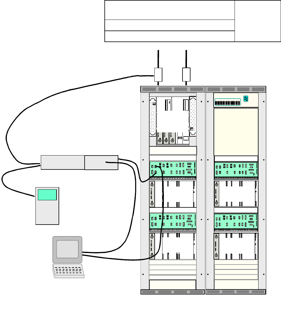
3. Architecture Overview
The Commissioning Unit architecture as depicted in Figure 1. Components
comprise:
i. Commissioning Unit
ii. Cables and couplers to allow the Commissioning Unit to be connected to
the RF sub-system.
iii. Cables to allow the Commissioning Unit to be connected to each Modem
Shelf (to support communications to each Shelf Controller).
iv. Associated system firmware upgrades required to support AGC operation
in cards such as the Shelf Controller.
4. Principles of Operation
The Commissioning Unit acquires a full low rate RF downlink / uplink through
RF cabling coupled into the CT transmit / receive antenna ports. Knowledge of
the path loss between the Commissioning Unit and RF antenna port allows the
Commissioning Engineer to adjust RF receive level as required using AS8100
Sitespan.
The Commissioning Unit scans and acquires a CDMA link to allow a specific
RF channel to be quickly adjusted during commissioning (or re-checked by a
visiting maintenance engineer)
AS4000 DA CT Commissioning Unit
Operators Manual GSI 002
605-0000-455
Issue 2.0. Date 21/03/00
Page 12 of 28
CT Rack Expansion Rack
Modem
Shelf 1
RF
Combiner
Shelf
Modem
Shelf2
Modem
Shelf 3
Modem
Shelf 4
Commissioning
Unit
TX/RX Shelves 1&2 TX/RX Shelves 3&4
PC with Sitespan
and LAT terminal
software
Power Meter
DC
Supply
Figure 1. DACU Connections to AS4000 DA CT Rack
AS4000 DA CT Commissioning Unit
Operators Manual GSI 002
605-0000-455
Issue 2.0. Date 21/03/00
Page 13 of 28
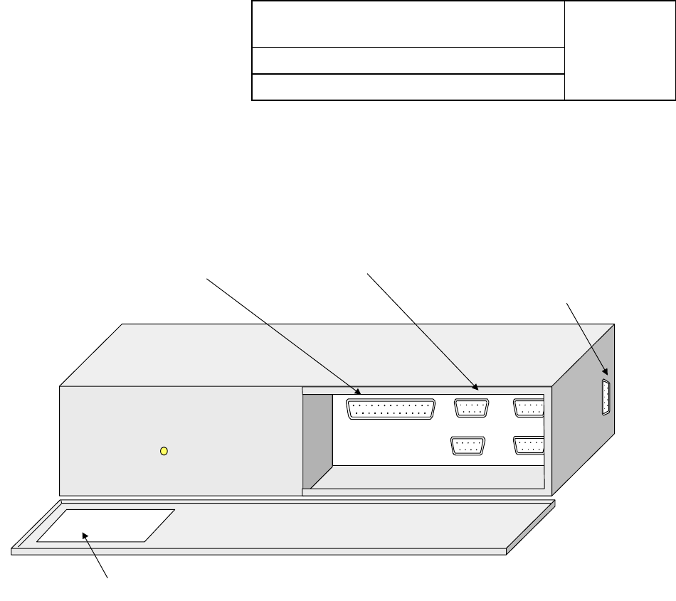
5. DA Commissioning Unit
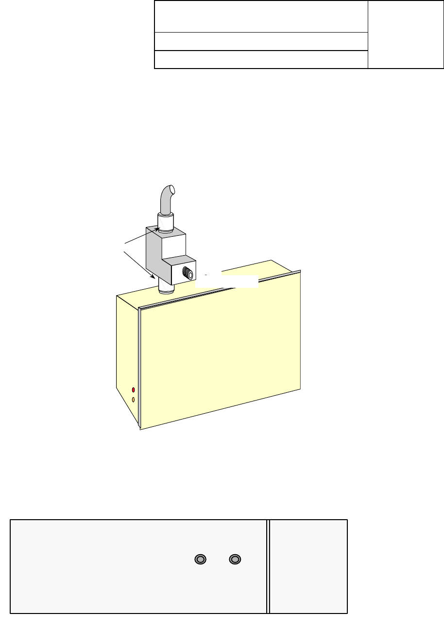
5.1. Mechanical
The Commissioning Unit measures 600mm wide, 300mm deep. 100mm high
and can be rack mounted if required.
Power from FAN
Connection
2 3 7
Not Used Pots Line 1
OK
LAT Terminal To modem shelves
Calibration Table
LAT Terminal/
Null modem AGCMON/
PCMON
AS4000 DA CT Commissioning Unit
Operators Manual GSI 002
605-0000-455
Issue 2.0. Date 21/03/00
Page 14 of 28
5.2. RF Interconnect
The Commissioning Unit has two RF ports (SMA connectors 50 Ohm
impedance) the RF lead is connected to port A and to the RF antenna port
using one length of RF cable and one coupler per antenna port. Unused ports
are terminated using 50 ohm RF loads. All couplers and cables are marked to
show insertion loss.
DIP/LNA
J1
J2
J3
Antenna Feed
80 dB Coupler
SMA connector
N type connector
5.3. Power Meter Connections
The Power meter is connected to the transmit port (B) on the DACU
Dip/
LNA
TX
Filter
Left Side
AB
AS4000 DA CT Commissioning Unit
Operators Manual GSI 002
605-0000-455
Issue 2.0. Date 21/03/00
Page 15 of 28
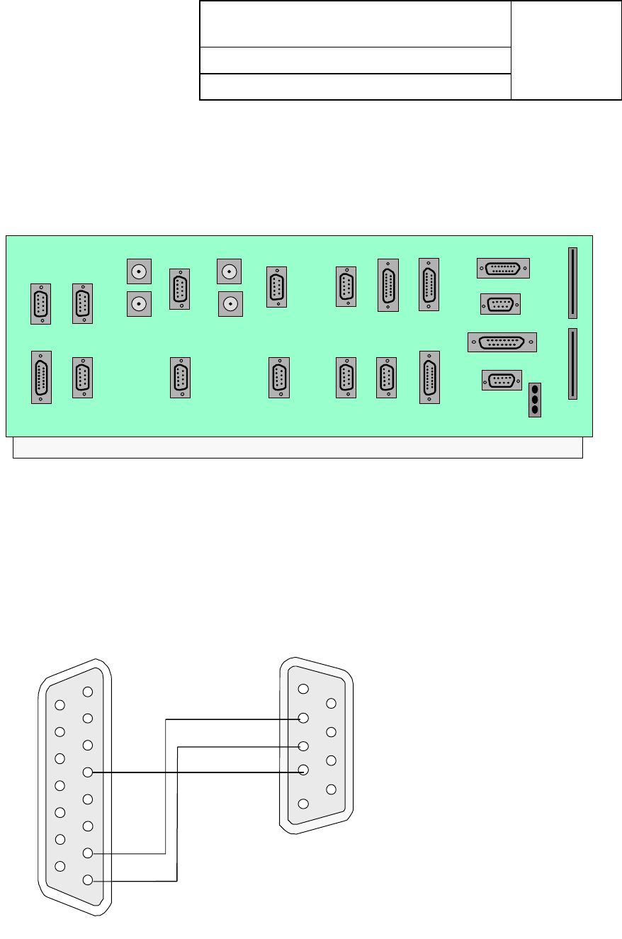
5.4. Shelf Controller Communications
Connect to the management system port of the modem shelf to the
Commissioning Unit D-type labelled AGC/PC MON.
A female 25 pin D type connection is presented on the adapter for connection
to the LAT Terminal.
SITESPAN 2 SITESPAN 1
SLOT 5 SLOT 9
E1IN
E1IN
E1OUT E1OUT
CABINET RACK CONTROL 55B ALARM
COMBINER
BASEBAND
DOOR LED
RF CAL
-48V FAN AUX5 AUX9
SCAUX
SCLAT
JTAG
-48VB
-48VA
BATTPOS
COMBINER BASEBAND
E5 E5
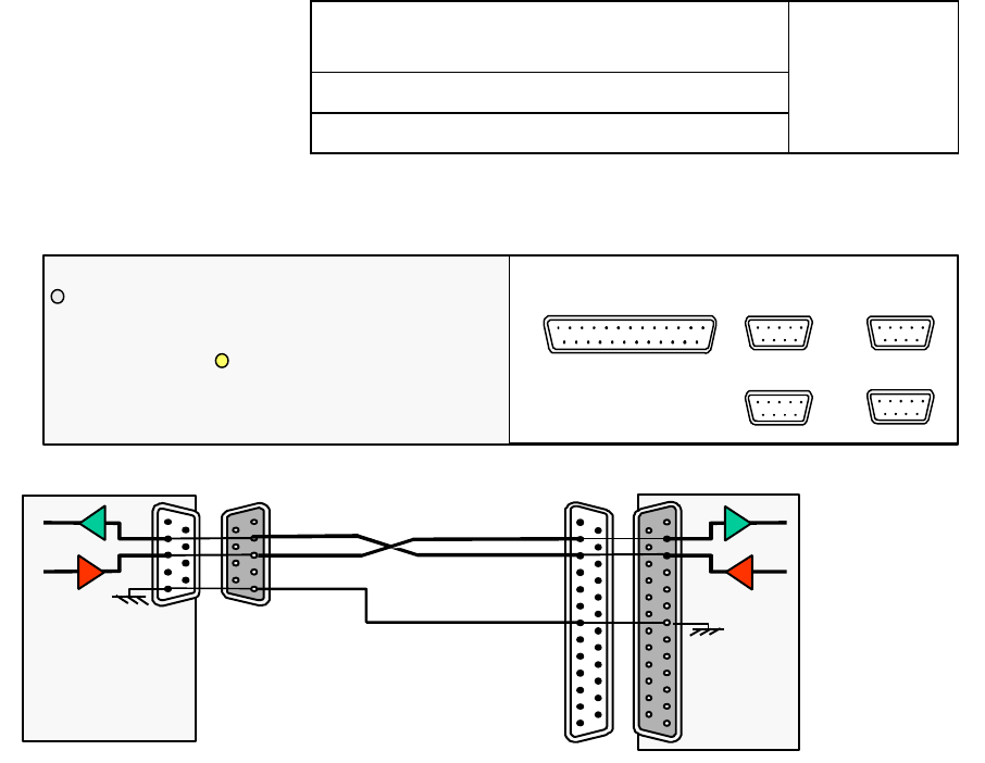
5.5. DC Connections
The DC Supply is connected to a 15 way D-type connector on the right side of
the unit. The Battery return is connected to pin 4 and duplicated supplies to
Batt-ve(0) to pin 8 and Batt-ve(1) to pin 7 . The DC supply can be obtained
from the FAN D-Type connector (P17) on the Modem Shelf connector panel.
15 Way Female
Commissioning Unit
9 Way Female
Fan Connection
on Modem Shelf
2
34
7 84
AS4000 DA CT Commissioning Unit
Operators Manual GSI 002
605-0000-455
Issue 2.0. Date 21/03/00
Page 16 of 28
5.6. Connect LAT Terminal
Connect LAT terminal to the terminal Port on the DACU
1 1
1
1
237
LAT Terminal
(null modem) AGCMON
and PCMON
Not Used POTS Line 1
LAT Terminal
OK
The connecting lead details are shown below
9 Female
PC
23 5
2
3
5
DACU
237
25 Male
2 3 7
The following Terminal Settings are used when connecting a PC LAT terminal
to a DACU:
Communications
Baud rate = 9600
Data bits = 8
Stop Bits =1
Parity = None
Flow Control = None
Text Transfers
Flow Control = Line at a time
Delay between Lines = 1 sec (10/10)
Block Cursor Word Wrap at Column = 79
Terminal Preferences
Columns = 80
Cursor =Block with Blink
Buffer Lines = 100
AS4000 DA CT Commissioning Unit
Operators Manual DLP 001
605-0000-455
Issue 2.0 Date 21/03/00
Page 17 of 28 © Copyright Airspan 2000
CENTRAL TERMINAL COMMISSIONING USING THE
DACU
1. Preparation for Commissioning at the Central Terminal
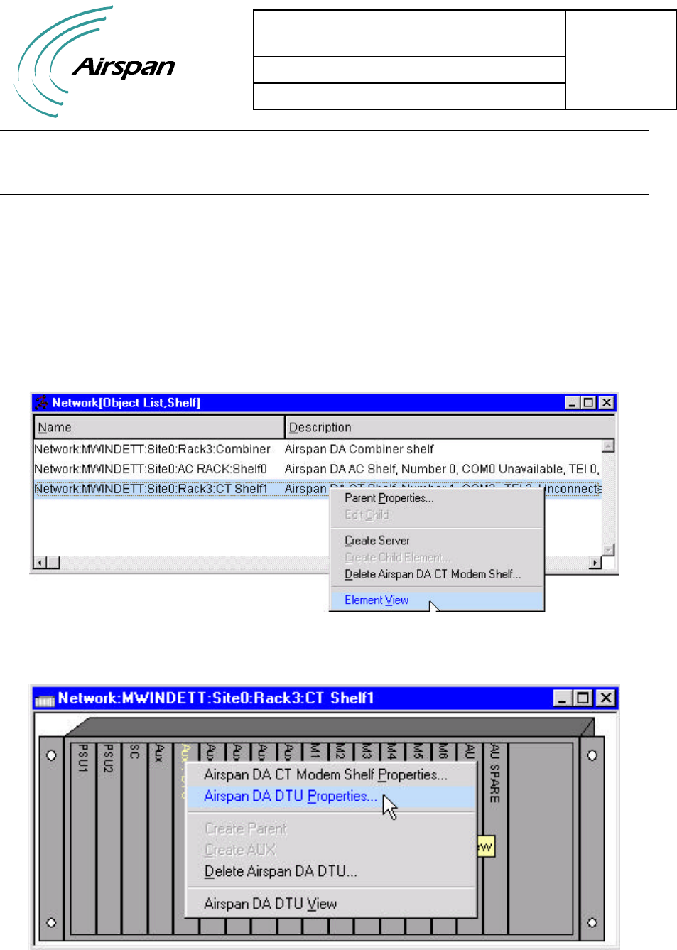
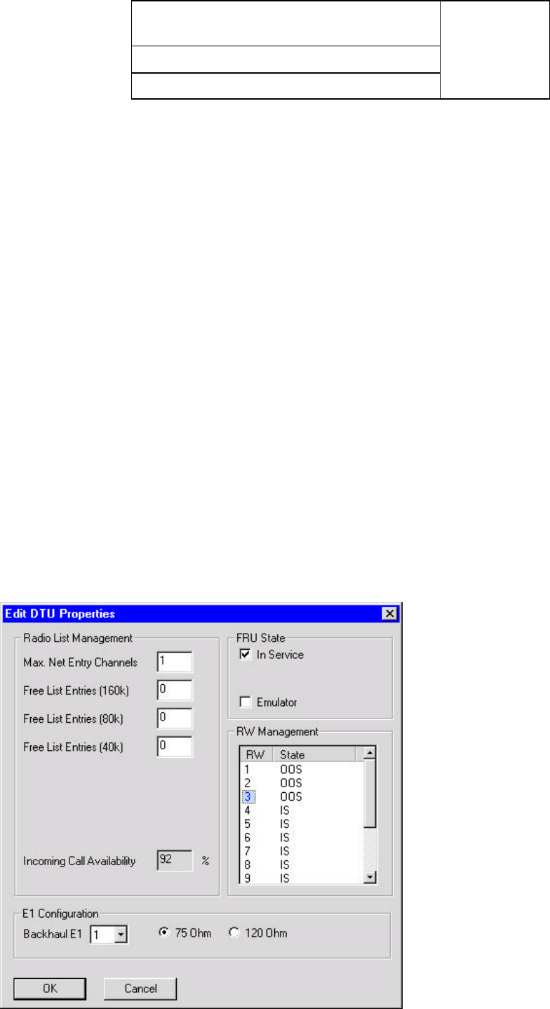
To make it possible for the test DACU to acquire a link the RW Management and Net Entry
has to be set via the AS8100 Sitespan as follows:
1. From the Object List Shelf view select the modem shelf, click right mouse button and
select the ‘element view’
2. Select the DTU on the modem shelf and click right mouse button, select Airspan DTU
properties
3. In the Edit card state window set max net entry channels to 1, set the number of Free
list entries at 160K 80K and 40K to 0.
AS4000 DA CT Commissioning Unit
Operators Manual DLP 001
605-0000-455
Issue 2.0 Date 21/03/00
Page 18 of 28
4. In order to acquire a test radio link using an ST, Sitespan must be used to place RW
codes ‘Out of Service’ (OOS) for either 10k or 160k bandwidths. These can be selected
from the DTU card properties. The options for each RW code are:
• IS - The RW is in service
• OOS - This takes the RW out of service.
• OOS(10k) - This puts the RW in Test Mode, allocating a 10kbit/s
bandwidth.
• OOS(160k) - This puts the RW in Test Mode, allocating a 160kbit/s
bandwidth.
The DTU card view shows all of the RW codes, and their current state within the
system (i.e. OOS or IS).
IMPORTANT NOTE: An RW code can only be placed Out of Service if it is currently
not in use by the system. Before proceeding, it is important that the DTU card view is
checked, to ensure that the RW code is in the desired state.
5. In the RW management window place the mouse pointer over the IS for RW 1 click
left mouse button until OOS is selected. Repeat for RW2 and RW3 to prepare for
commissioning. Once RW codes have been reserved for Test links, the ST can be
programmed in the usual method, although the RW channels that the 10kbit/s and
160kbit/s links are acquired on, must be the same as the ones set-up in the DTU card
properties (i.e. NOT RW 15!).
AS4000 DA CT Commissioning Unit
Operators Manual DLP 001
605-0000-455
Issue 2.0 Date 21/03/00
Page 19 of 28
2. Power Cycle the Rack
The rack should be power cycled.
3. Check DACU Calibration
Each DACU is provided with a calibration table on the cover unit a typical table is
shown below. The path loss is equal to the sum of the unit losses and external losses.
Cable
Loss dB Coupler
Loss Unit loss RX
sensitivity Power meter
Reading
1 80 17 -98 -3.68
2 80 17 -99 -2.68
3 80 17 -100 -1.68
4 80 17 -101 -0.68
5 80 17 -102 +0.32
Table 1. DACU Calibration Table
4. Set Rx Sensitivity
1. Type:Acc> TE 0
Acc> WU C 1 4000d 0 0 0 (where 4000d indicates version 4.13)
Acc> WU F A
2. Program the DACU via the LAT port to the correct frequency, PN code and ID
number.
3. Set RW.
WU I 1 1 1 1
WU W
WU I <stid> <pn> 0 1
Where <Stid> is in HEX, 17 dec = 11 hex, and pn is 1 in most cases.
4. Write data into ST:
- WU W
5. Once the DACU has booted-up, put it into test mode by typing: TE 0.
6. Note: A configured DACU cannot maintain its uplink without being registered by the
management system. The DACU becomes registered when its ESN is entered into the
management system database. A registered ST can acquire the uplink and maintain
periodic information exchange with the shelf’s SC.
The ‘LK’ command forces the DACU to acquire a link as follows:
RW
Code PN
Code Up Link
Rate * Down Link
Rate* Overlay
code Frequency channel number
within channel plan
LK 8 1 4 4 0 9
AS4000 DA CT Commissioning Unit
Operators Manual DLP 001
605-0000-455
Issue 2.0 Date 21/03/00
Page 20 of 28
* The rate at which the link will acquire is defined as follows:
1: 10kbit/s
240kbit/s
380kbit/s
4: 160kbit/s
7. For testing type in the code relating to the system as set up i.e. LK 7 1 4 4 0 9. In the
example above the DACU is forced to acquire on RW 7, PN 1, with Uplink and
Downlink of 160kbit/s, using RF channel 9 within the RF band.
With the LAT connected to the DACU, ensure that it has booted-up.
Type: LK F 1 1 1 0 1 to set channel 15 and LK 1 1 1 1 0 1 to set channel 1 or LK 2 1
1 1 0 1 to set channel 2.
8. Type W 426 to monitor link state.
9. The DACU will return with:
Display Interpretation
D: 0426 0000 No Link
D: 0426 0101 Downlink Acquired
D: 0426 0303 Uplink Acquired (transitory state)
D: 0426 0B0B Uplink Acquired
D: 0426 0808 * Downlink has failed
D: 0426 0909 * Uplink has failed
*Note: relate to a link failure
Table 2 Link States
10. Once the DACU acquires the link, the RX gain can be commissioned. If the link does
not acquire, then it will be necessary to change the RX gain through Sitespan. To
check if the Link has acquired check the Green LED is illuminated on the Modem
Card. The top 4 LEDs show the first modem at the different acquisition rates and the
next 4 LEDs show modem 2.
11. Using Sitespan highlight the shelf, and edit ‘parent properties’.
12. Select ‘Airspan DA CT modem shelf’.
13. Adjust the ‘Rx Gain’ by increasing and decreasing the values. Note: To start with, set
the RX gain to around 2200. ( if value is reduced power goes UP). Check the output
power of the DACU, and repeat until the output power matches that in the DACU
Calibration Table.
14. Record the result. The values of the TX and RX gain must be set into the Sitespan at
the AC before the backhaul is connected to the CT, failure to do this results in the TX
power and RX sensitvity values being overwritten by the value stored in the Sitespan
Server.

AS4000 DA CT Commissioning Unit
Operators Manual DLP 001
605-0000-455
Issue 2.0 Date 21/03/00
Page 21 of 28
15. When the Sitespan connects it configures the OOS and Net Entries but as a precaution
it may be prudent to set all lists in the DTU properties to OOS.
16. Power off the DACU.
17. With the LAT connected to the DTU, restore the DTU from test mode by typing TE 1.
18. Disconnect the RF cables from the rack and connect the Antenna. The rack is now
fully commissioned.
5. Restoring shelf connections
1. Remove the test equipment and connecting cables.
2. Replace the Shelf covers and the protective cap on the coupler.

AS4000 DA CT Commissioning Unit
Operators Manual DLP 001
605-0000-455
Issue 2.0 Date 21/03/00
Page 22 of 28
This Page Intentionally Blank
AS4000 DA CT Commissioning Unit
Operators Manual ICL-001
605-0000-455
Issue 2.0 Date 21/03/00
Page 23 of 28 © Copyright Airspan 2000
ISSUE CONTROL LIST
Title Issue Date Issue Details
Title Page 2.0 March 2000 Update
ICL-001 2.0 March 2000 Update
IXL-001 2.0 March 2000 Update
GSI-001 2.0 March 2000 Update
DLP-001 2.0 March 2000 Update
CHANGE TYPE/DATE PURPOSE PAGES AFFECTED
Draft Issue #, Month
Year
Related Documentation
Demand Assignment
605-0000-450 System Overview
605-0000-451 System Operations and Maintenance Manual
605-0000-452 DA Central Terminal - Equipment Rack Installation & Commissioning
605-0000-453 Access Concentrator - Equipment Rack Installation & Commissioning
605-0000-454 Subscriber Terminal Installation & Commissioning
605-0000-427 AS8100 Sitespan User Guide

AS4000 DA CT Commissioning Unit
Operators Manual ICL-001
605-0000-455
Issue 2.0 Date 21/03/00
Page 24 of 28
This Page Intentionally Blank

AS4000 DA CT Commissioning
Unit
Operators Manual Abbreviations
605-0000-455
Issue 2.0 Date 21/03/00
Page 25 of 28 © Copyright Airspan 2000
Abbreviations
AC Access Concentrator
AGC Automatic Gain Control
CPE Customer Premises Equipment
CRU Customer Radio Unit
CT Central Terminal
DA Demand Assigned
DACU Demand Assignment Commissioning Unit
DTU Demand Assign Tributary Unit
DC Direct Current
DMM Digital Multi Meter
ISDN Integrated Services Digital Network
LAT Local Access Terminal
LD Loop Disconnect
LED Light Emitting Diode
MF Multi-Frequency
NTU Network Termination Unit
PC Power Control
PN Psuedo Random Noise
PSU Power Supply Unit
RF Radio Frequency
SC Shelf Controller
ST Subscriber Terminal
Rx Receive
Tx Transmit
VF Voice Frequency

DA Central Terminal Commissioning
UnitOperators Manual Abbreviations
605-0000-455
Issue 2.0 Date 21/03/00
Page 26 of 28
This Page Intentionally Blank

AS4000 DA CT Commissioning Unit
Operators Manual User
605-0000-455 Response
Issue 2.0 Date 21/03/00
Page 27 of 28 © Copyright Airspan 2000
User Response Form
Mail: Airspan Communications Limited Fax: (44) 895 4677182
Cambridge House
Oxford Road
Uxbridge
Middlesex
UB8 1UN
Document Rating Excellent Good Average Below Average Poor
Accuracy / Completeness qqqqq
Clarity / Organisation qqqqq
Figures qqqqq
Table of Contents/Index qqqqq
The nature of this response is Addition qDeletion qCorrection q
Please enter details of response below (include precise reference to Section, Page,
Paragraph)
Please Complete the following for acknowledgement/response:
Name: ........................................ Address ..........................................
Company ........................................ ..........................................
Job Title ........................................ ..........................................
Department ........................................ ..........................................
Telephone ........................................ ..........................................
Thank you for your co-operation and assistance.

AS4000 DA CT Commissioning Unit
Operators Manual User
605-0000-455 Response
Issue 2.0 Date 21/03/00
Page 28 of 28
This Page Intentionally Blank