Airspan Communications AS4020CT-PCS AS4020 Central Terminal PCS Basestation User Manual
Airspan Communications Limited AS4020 Central Terminal PCS Basestation Users Manual
UserManual.wiki
>
Airspan Communications
>
AS4020CT PCS User Manual
Users Manual
Navigation menu
Upload a User Manual
Namespaces
Wiki Guide
HTML
PDF
Info
Views
User Manual
Discussion / Help
Navigation


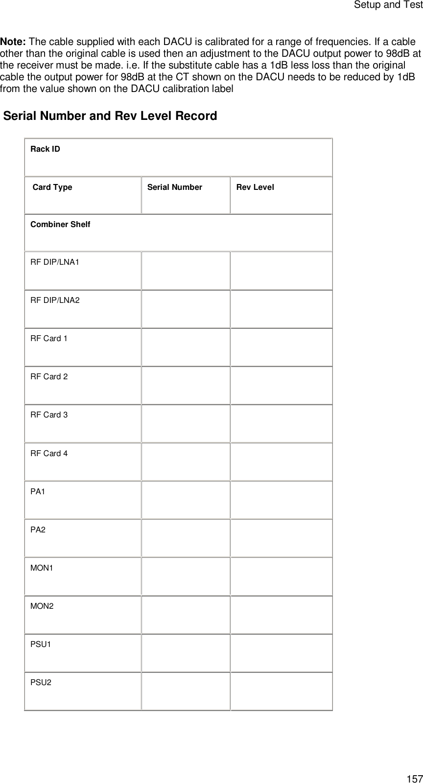
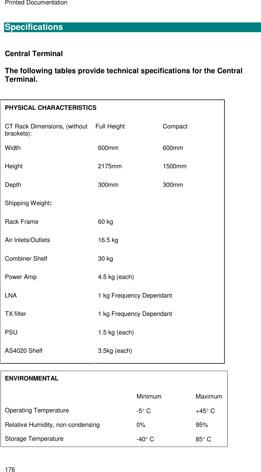
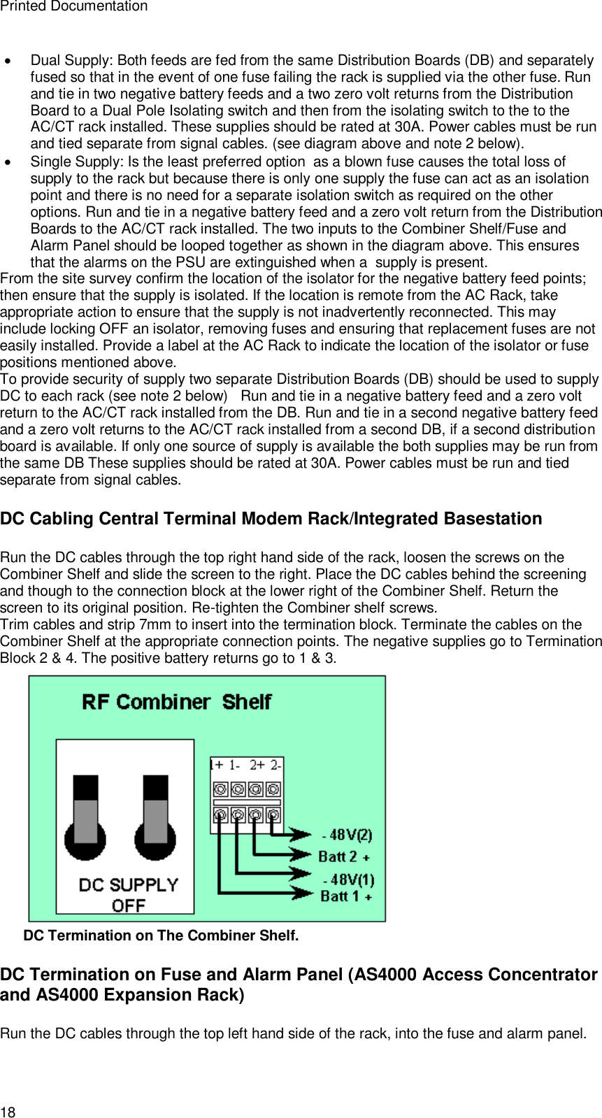
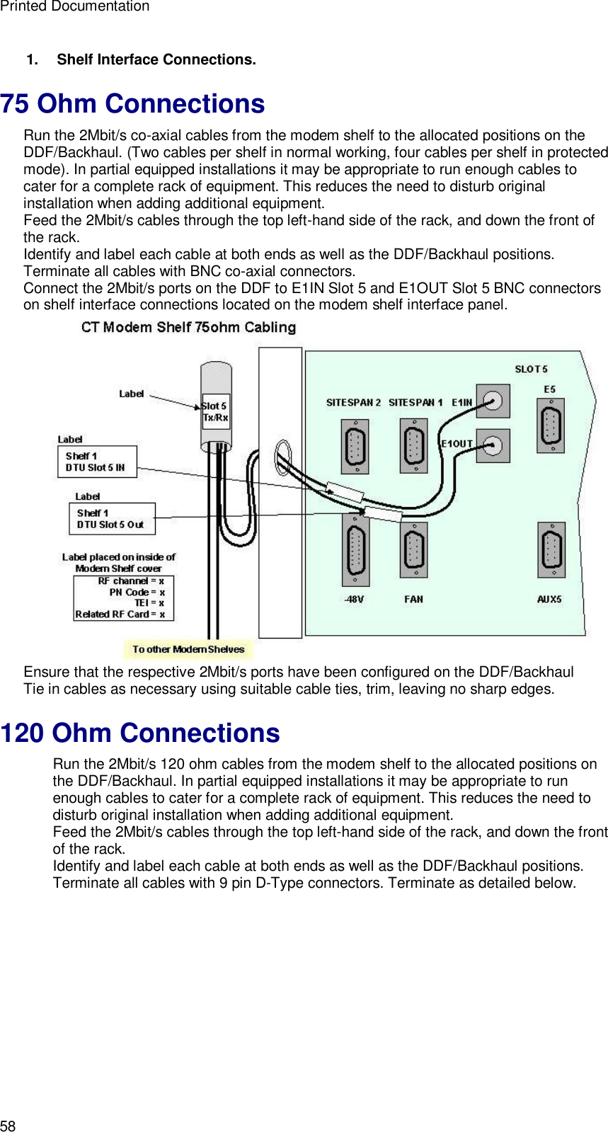
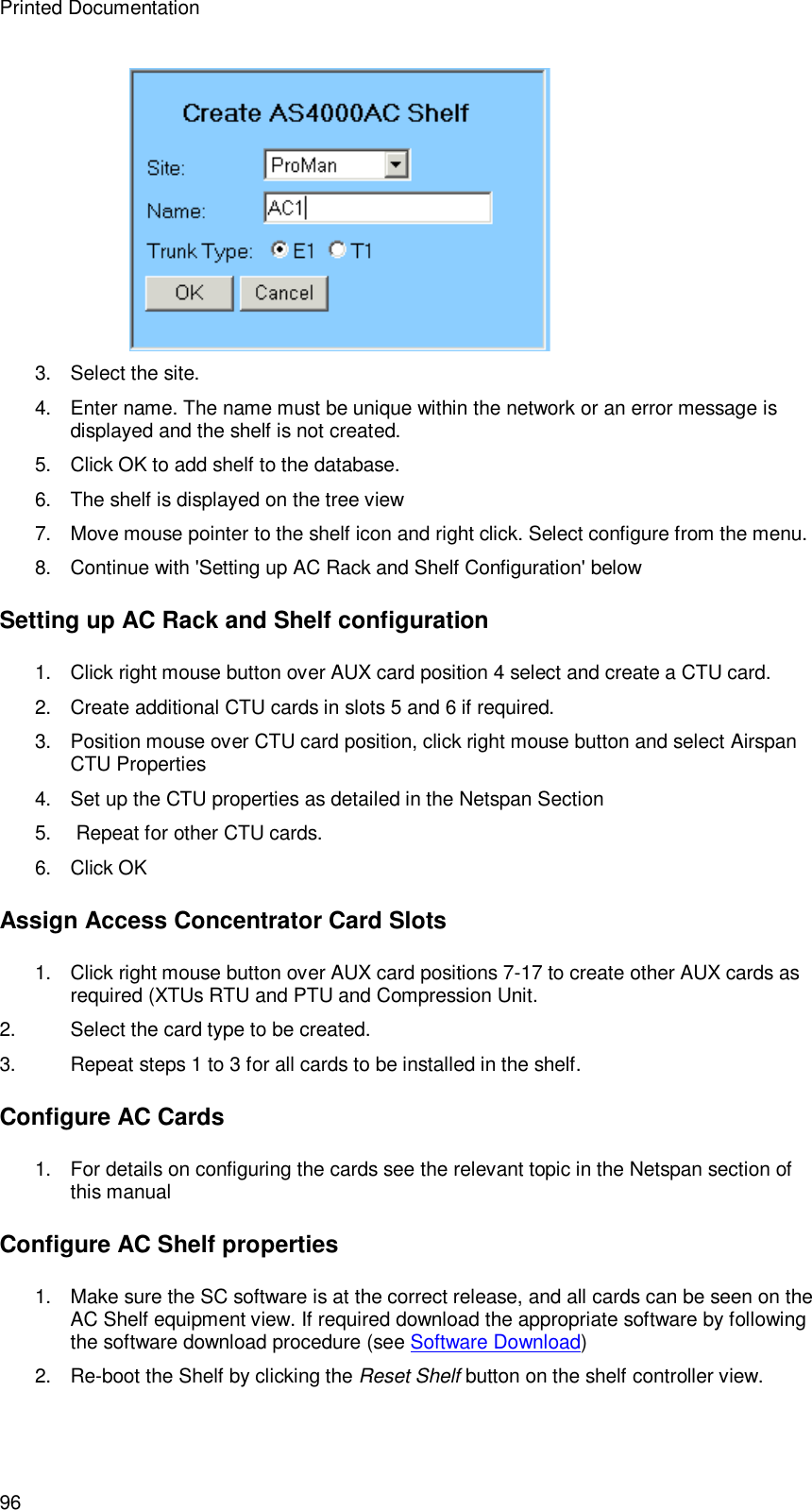
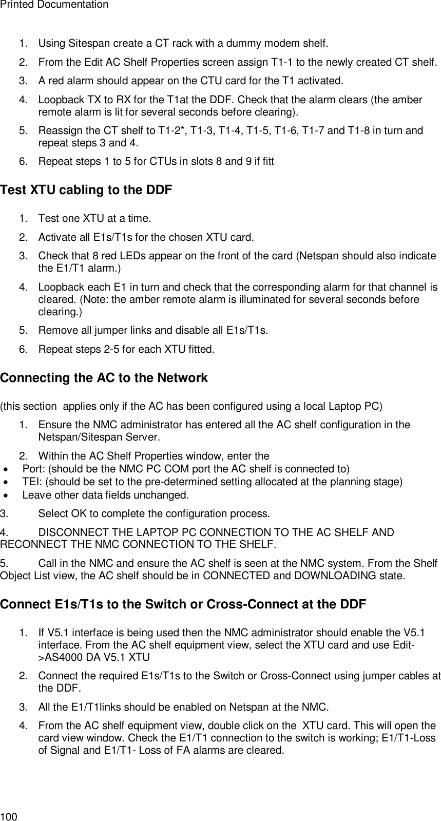
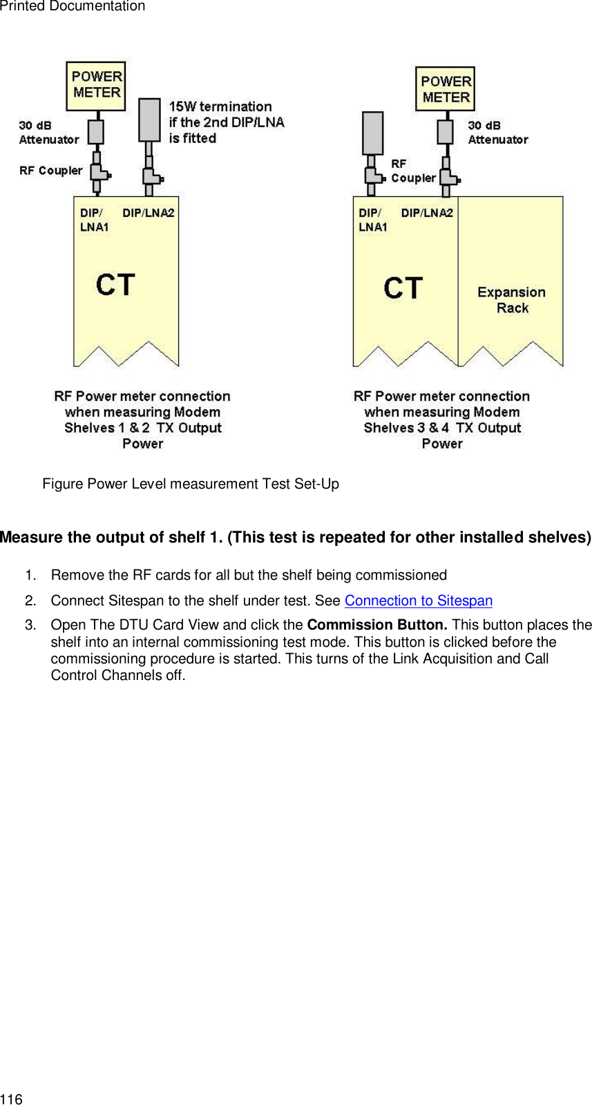
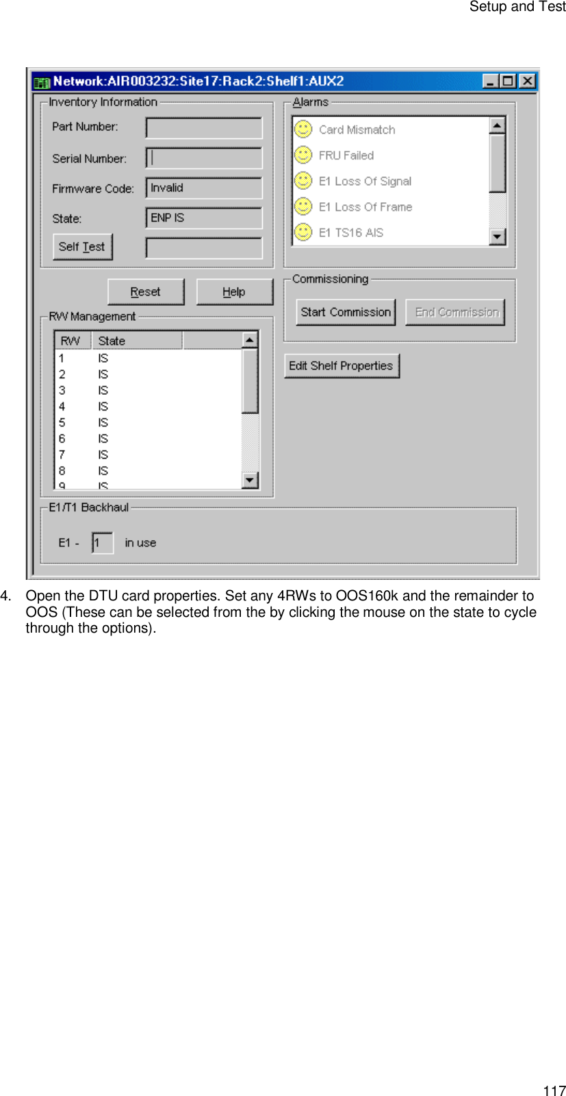
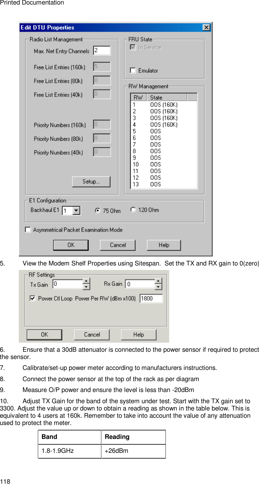
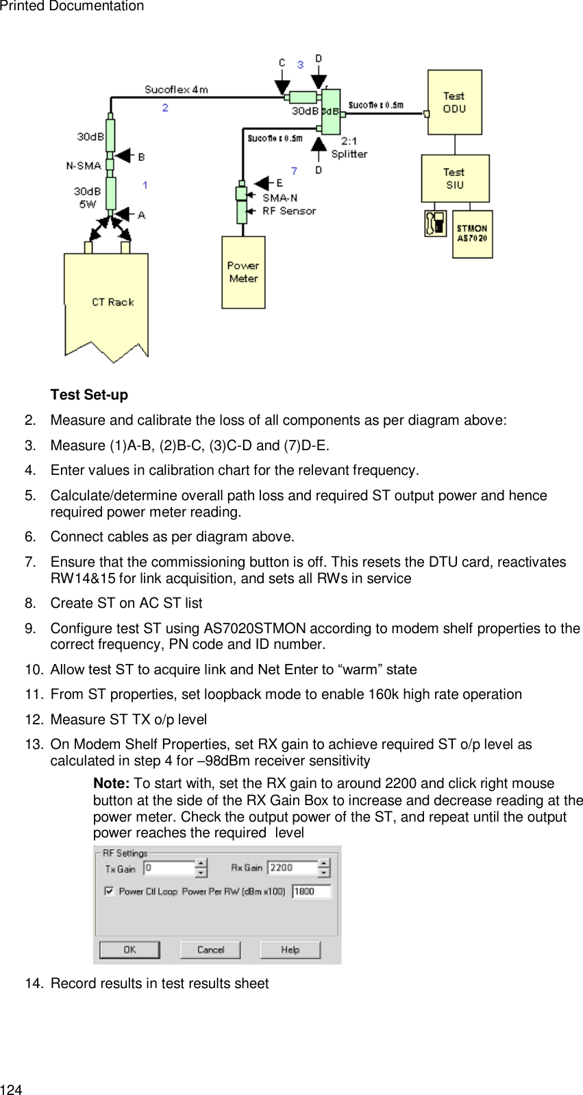
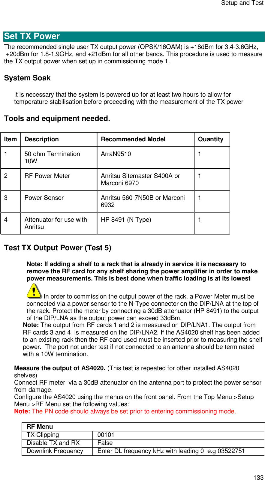
![Installation 15 DC Power and Alarm Cabling Rack Earthing Using the site survey, locate the building central [safety] grounding point. Run an earth cable rated at 30A to each rack and connect it to the centre earth stud located at the top or at the side of the rack. (only one external earth per rack) See illustrations below. These points are labelled with the IEC Earth symbol. Rack earthing at top Rack earthing at base Other external safety earth connections must not be made to the rack.](https://usermanual.wiki/Airspan-Communications/AS4020CT-PCS/User-Guide-446583-Page-19.png)


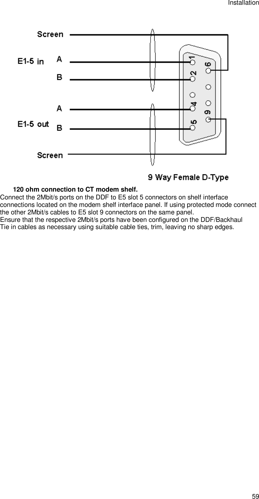


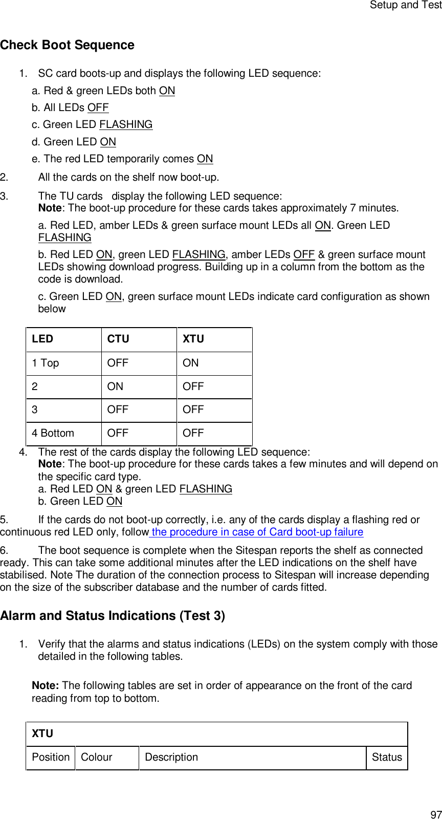

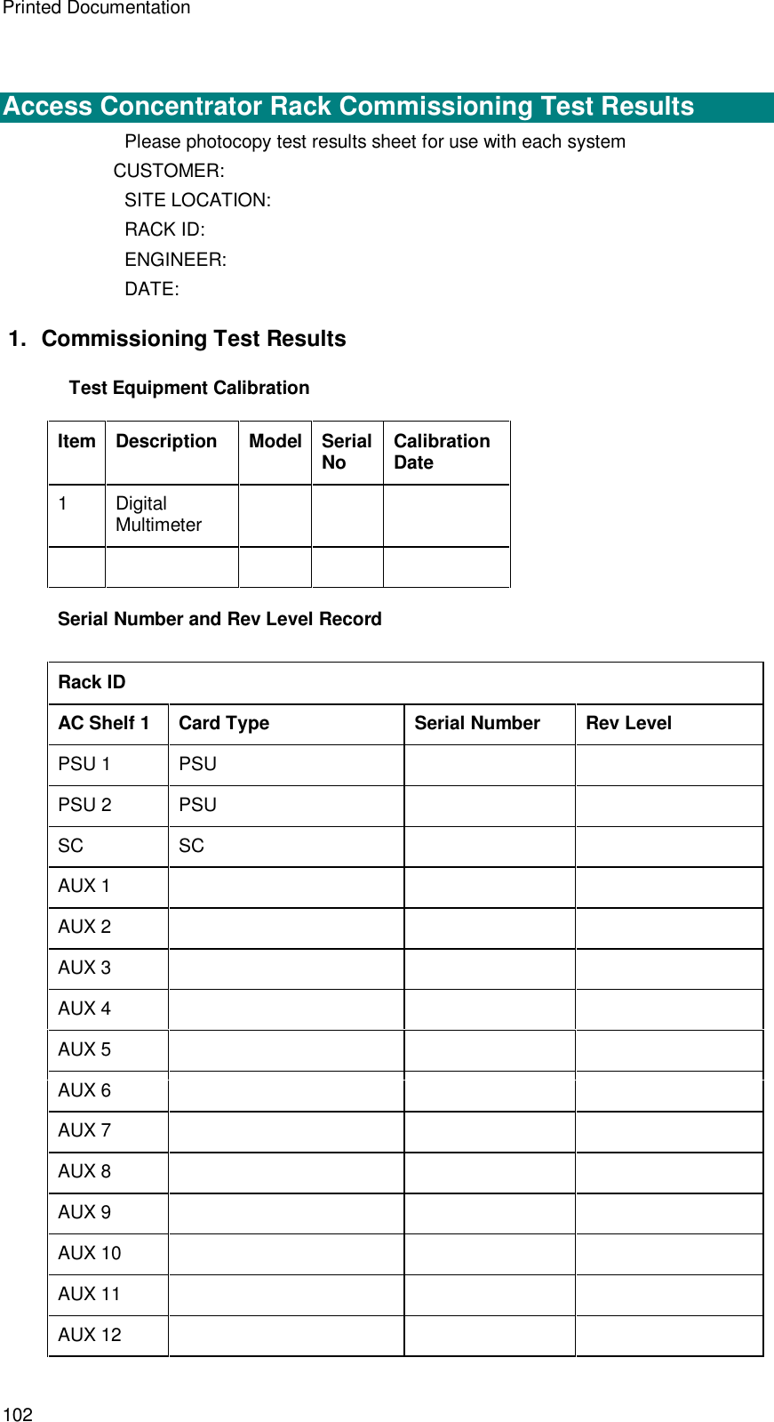

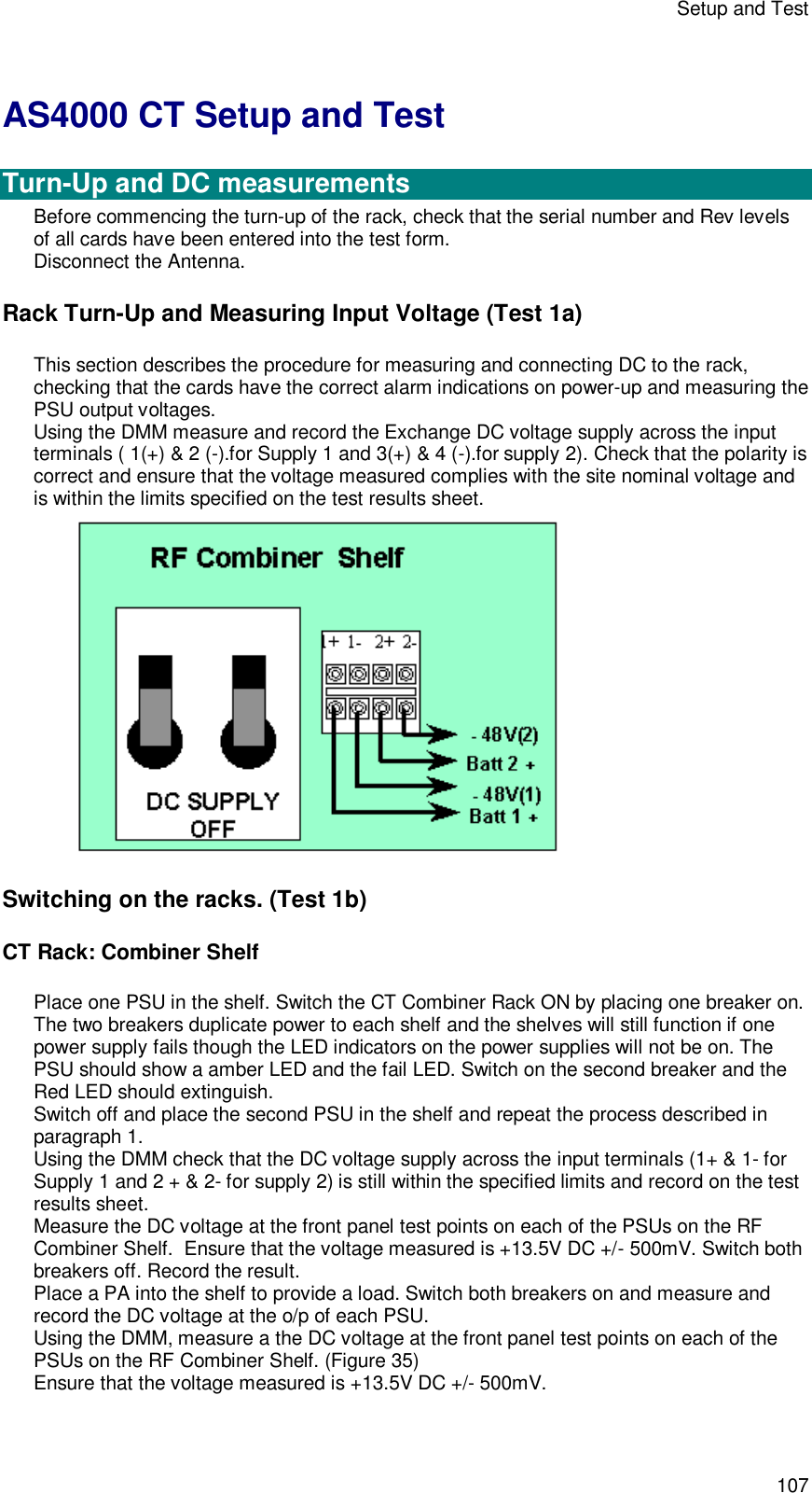
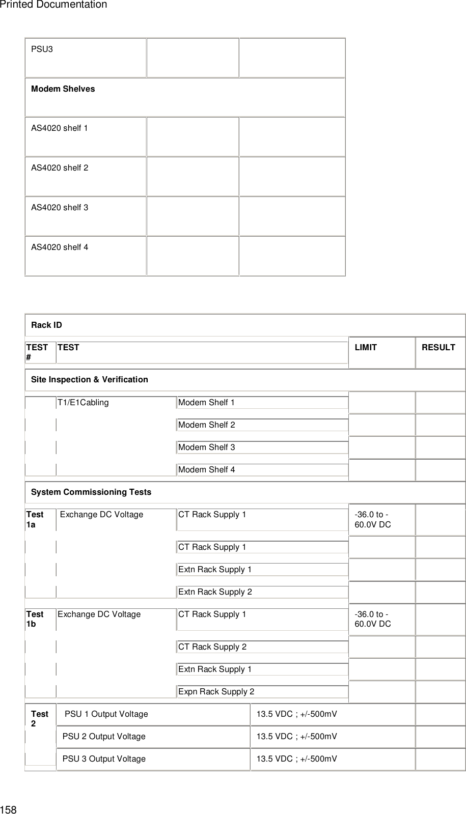
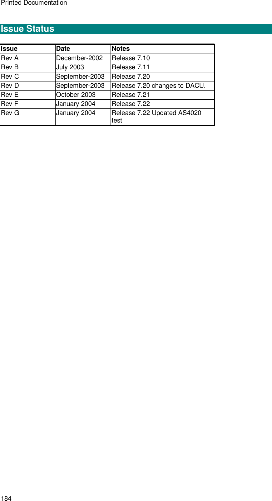
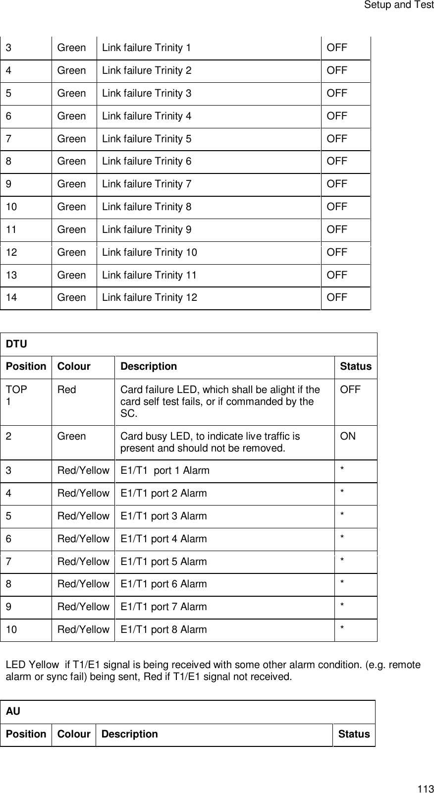
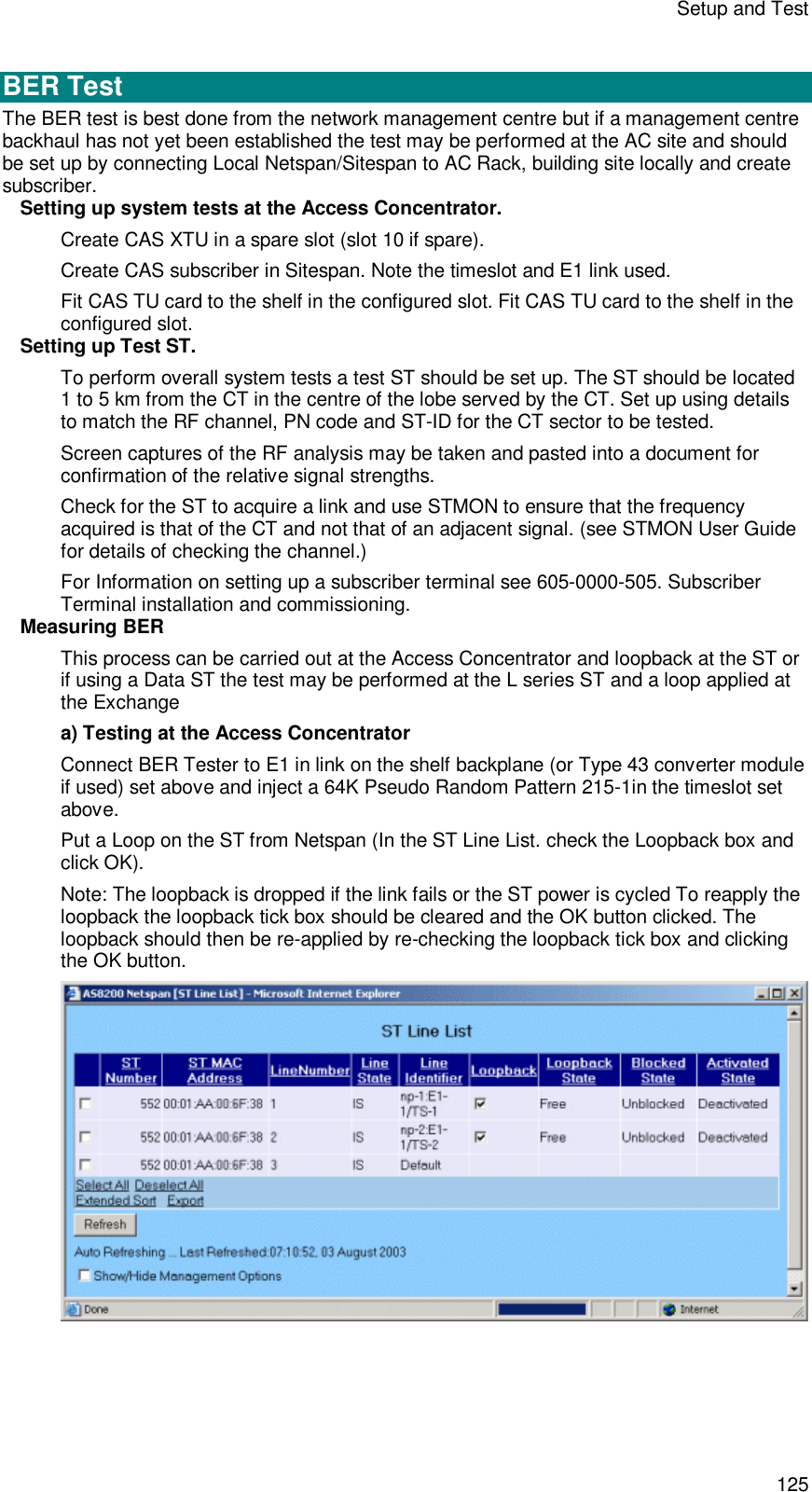
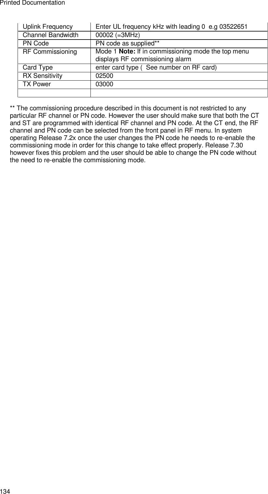
![Setup and Test 111 RF Combiner Shelf Low Noise Amplifier Position Colour Description Status Top 1 Amber Power/Module Status OK ON 2 Red Power Fault OFF RF Card [RF] Position Colour Description Status Top 1 Amber Power/Module Status OK ON 2 Red Power Fault OFF Shelf Monitor Position Colour Description Status Top 1 Red Power Fault/PA Module Fault OFF 2 Amber Power/Module Status OK ON Power Amplifier[PA] Position Colour Description Status](https://usermanual.wiki/Airspan-Communications/AS4020CT-PCS/User-Guide-446583-Page-115.png)
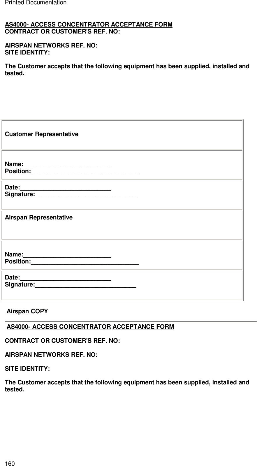
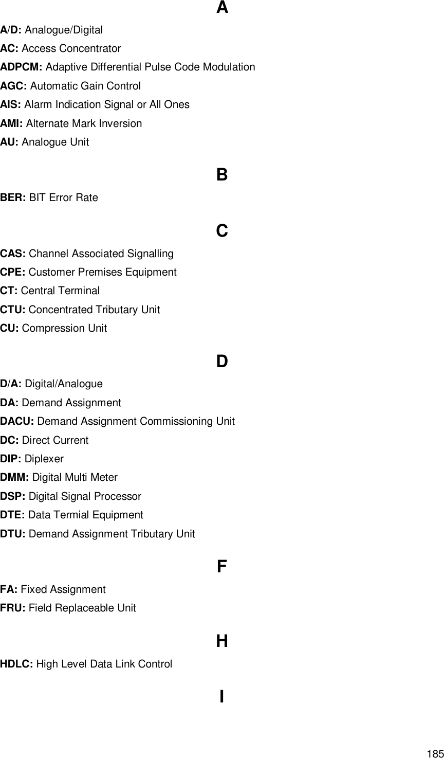
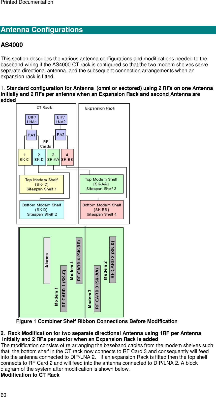
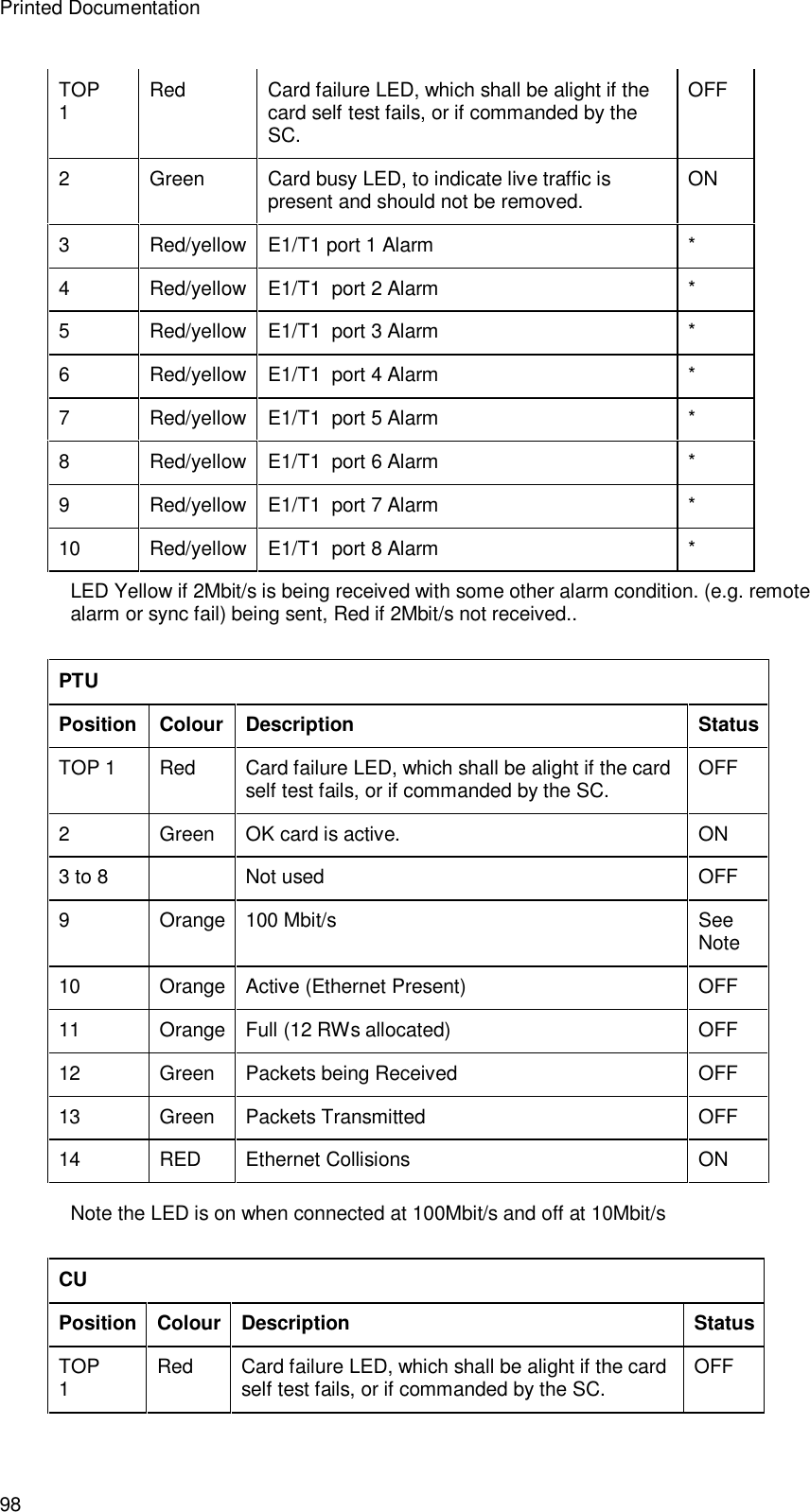
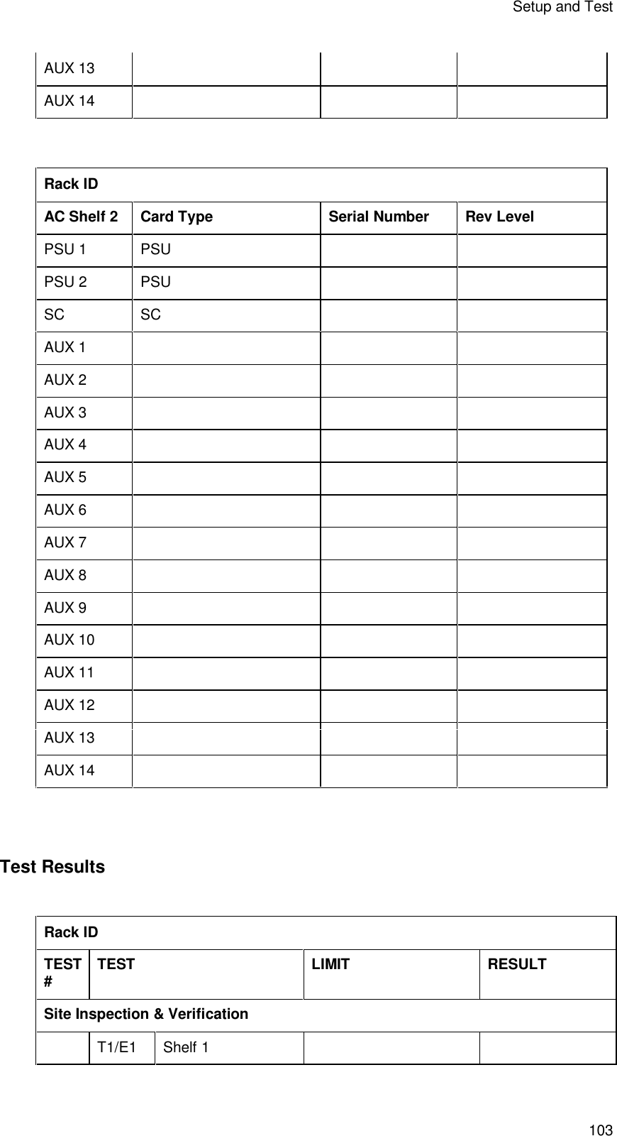
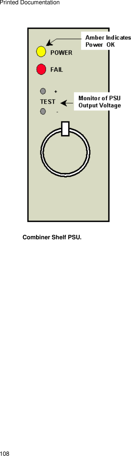
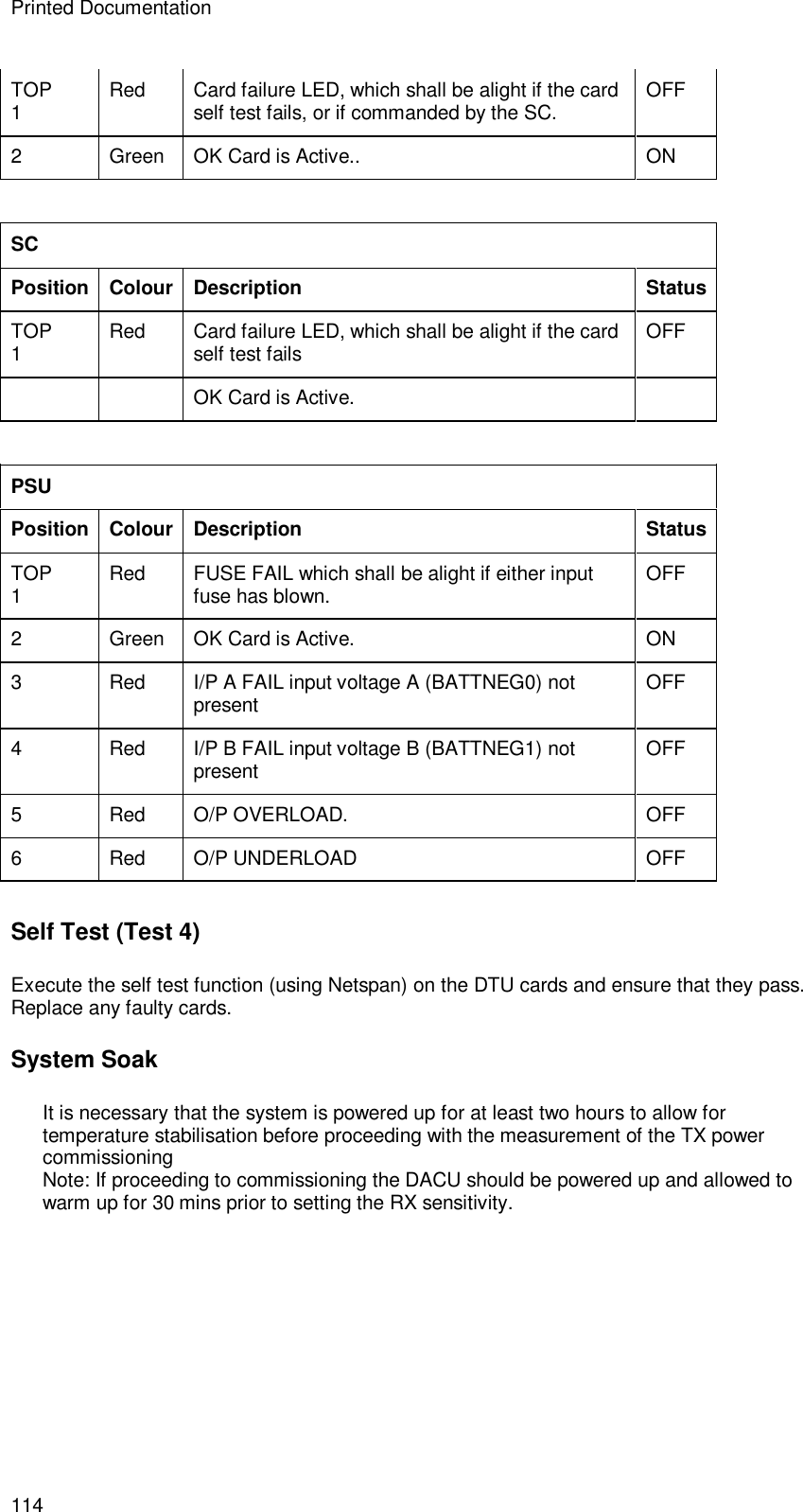
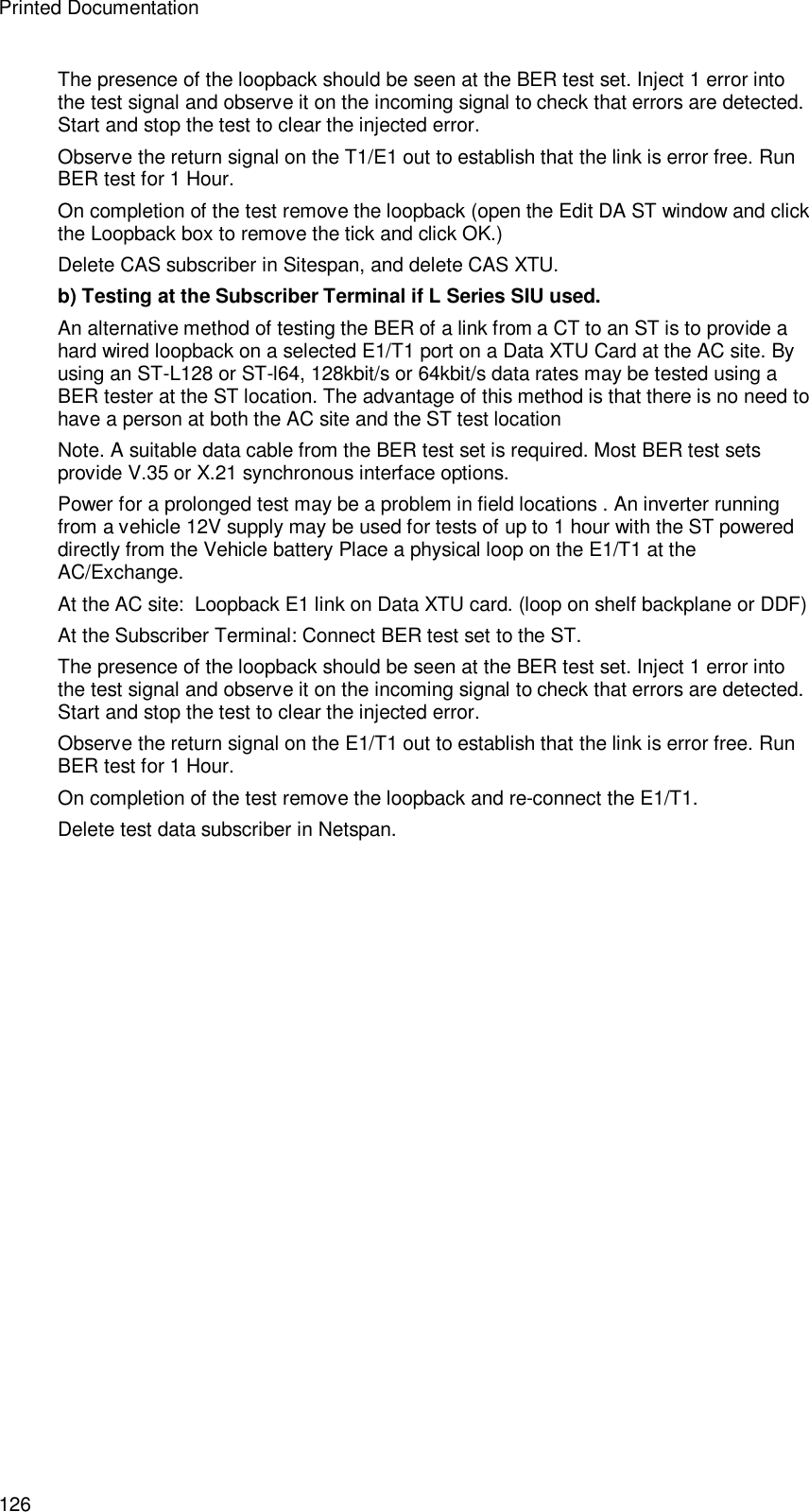
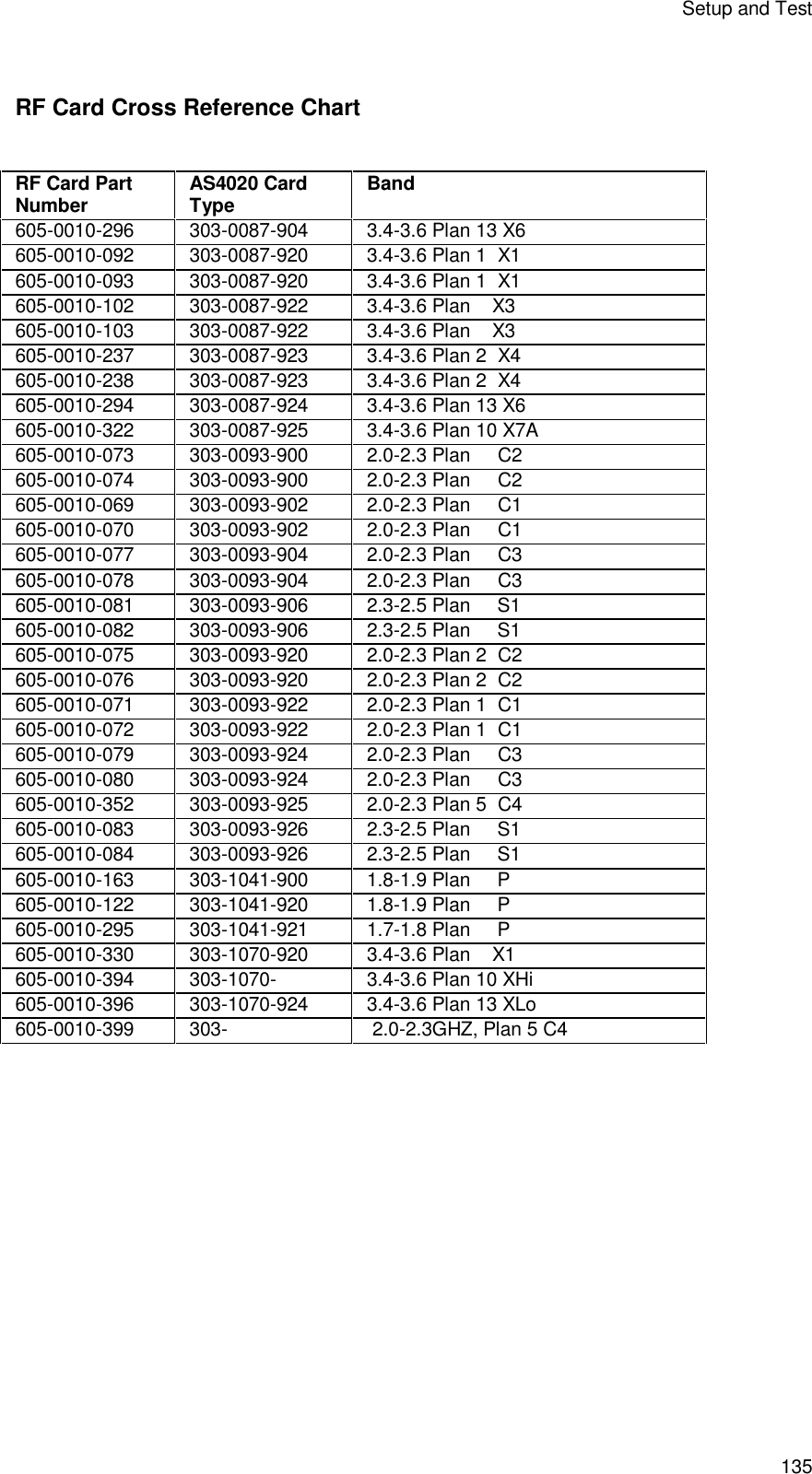
![Printed Documentation 112 Top 1 Amber Power/Module Status OK ON 2 Red Power Fault/PA Module 1 Fault OFF 3 Red Power Fault/PA Module 2 Fault OFF * PA 2 is inserted inverted and the alarm indicators are also inverted Power Supply Unit [PSU] Position Colour Description Status Top 1 Amber Power OK ON 2 Red Power Fail OFF Table. RF Combiner Shelf Card LED Indications. Modem Shelf Card LEDs. In normal state all LEDs will MODEM Position Colour Description Status TOP 1 Red Card failure LED, which shall be alight if the card self test fails, or if commanded by the SC. OFF 2 Green Card busy LED, to indicate live traffic is present and should not be removed. ON](https://usermanual.wiki/Airspan-Communications/AS4020CT-PCS/User-Guide-446583-Page-116.png)
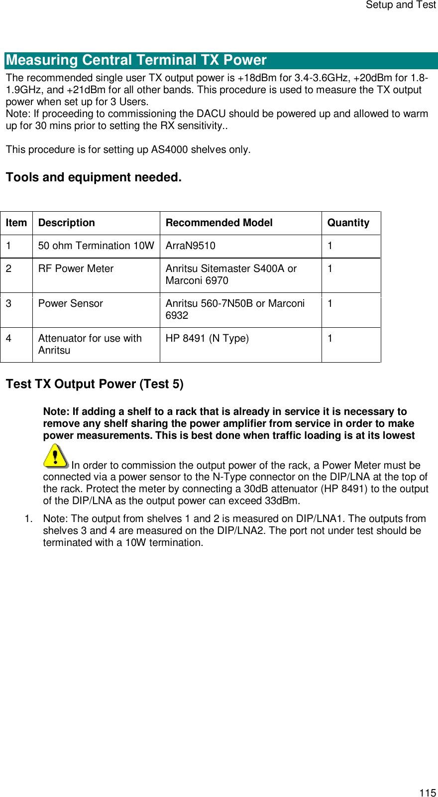
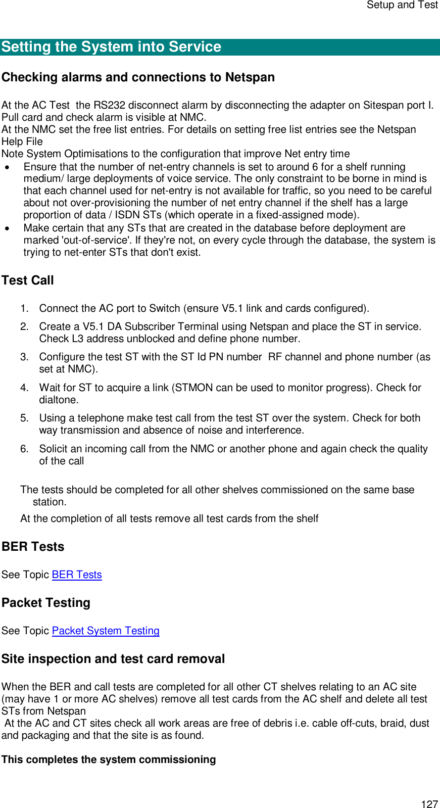

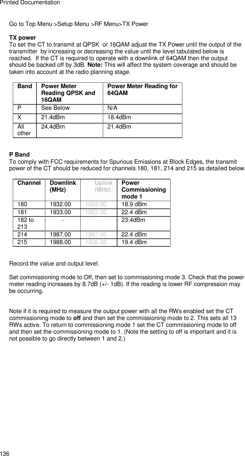
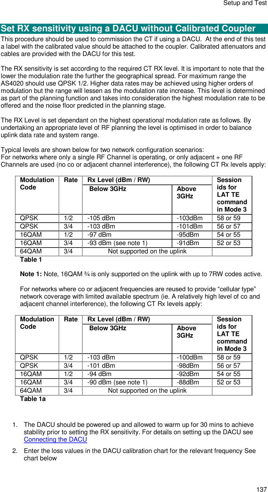
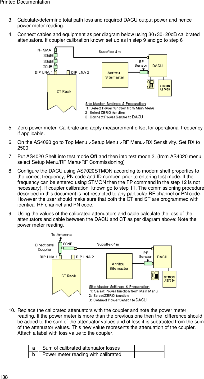
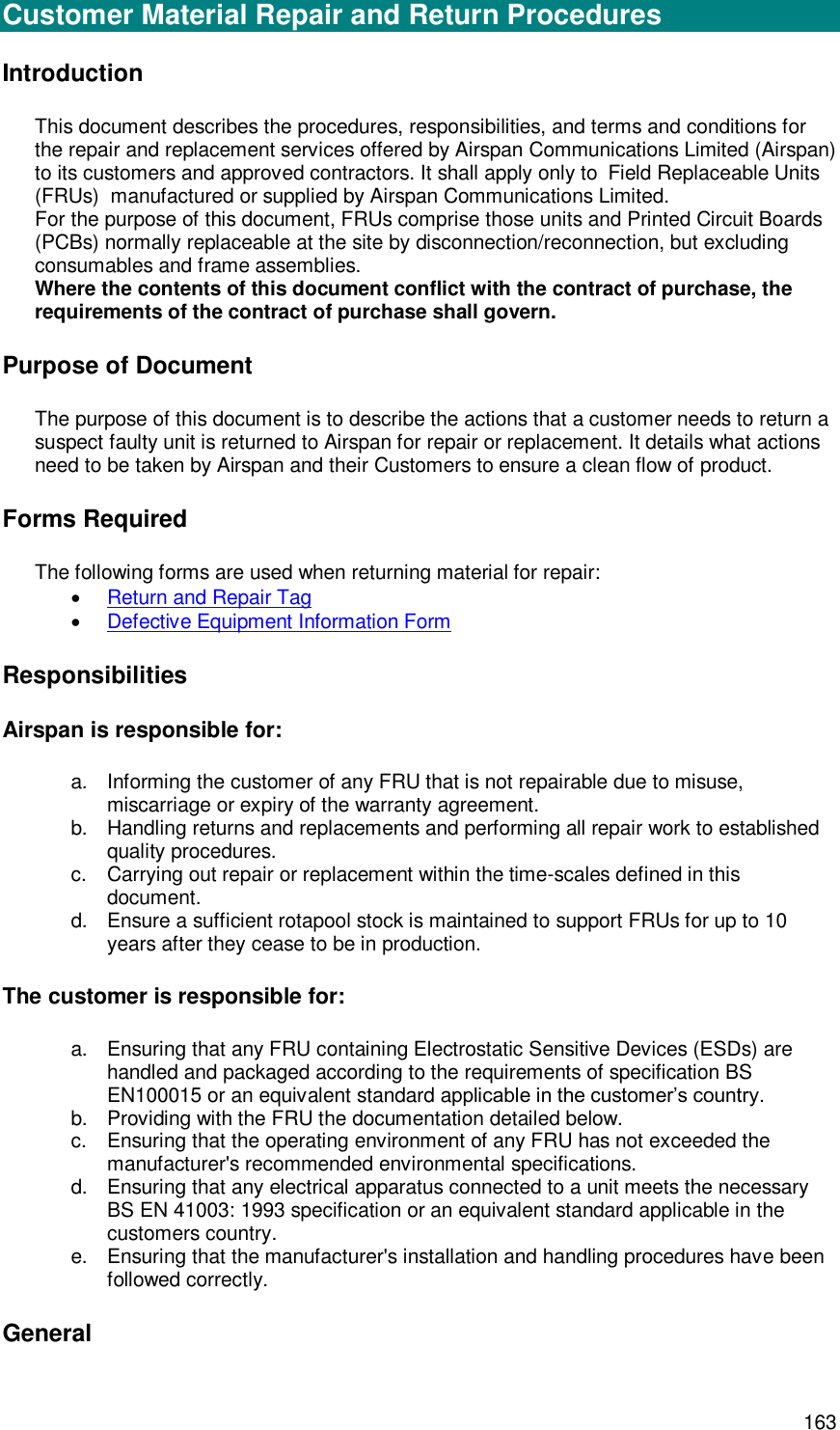
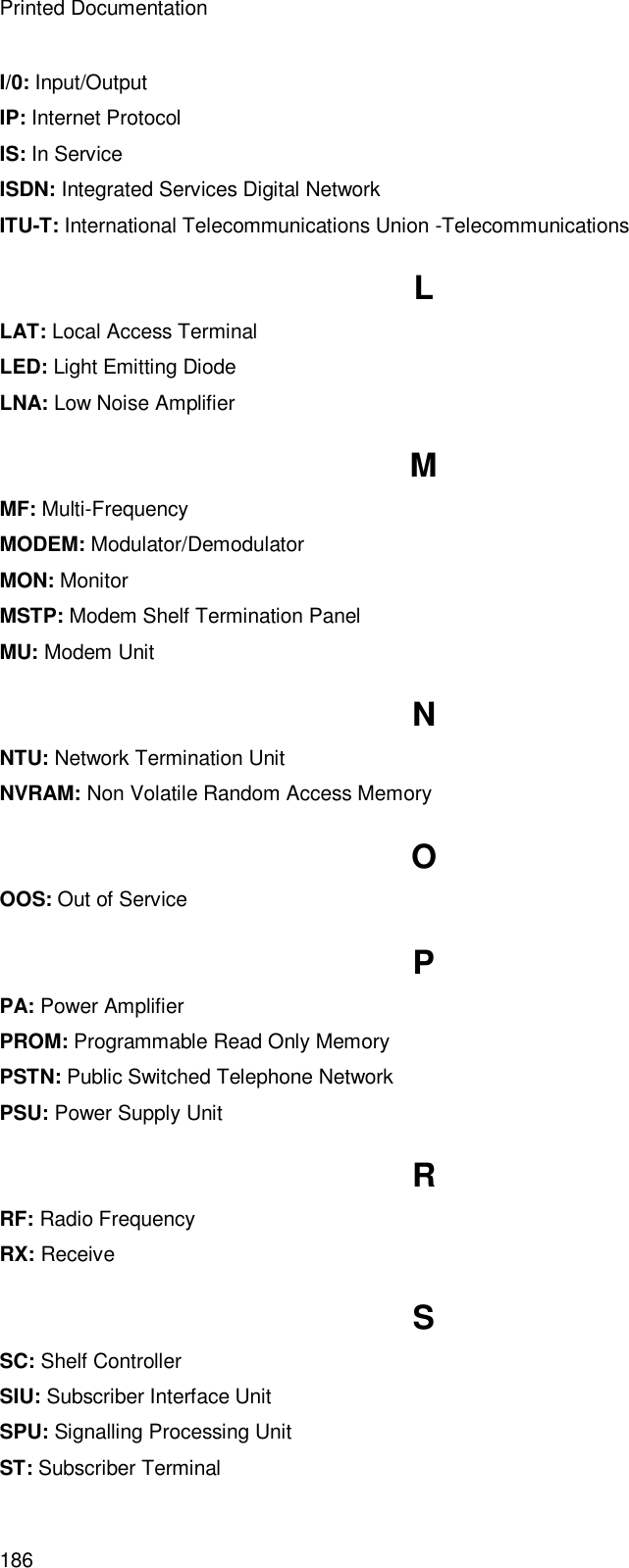
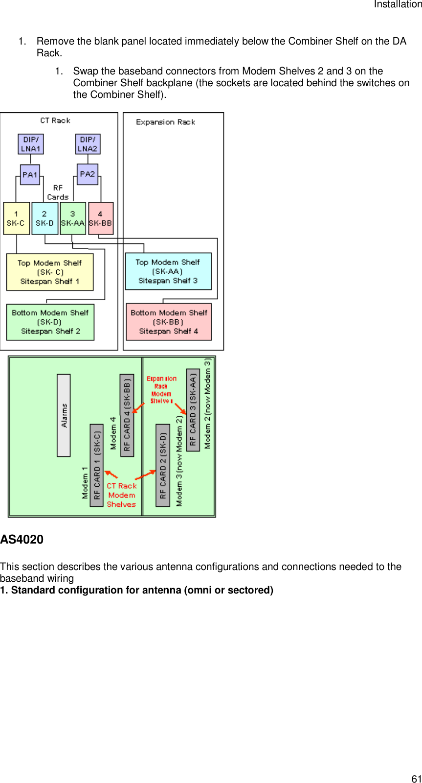
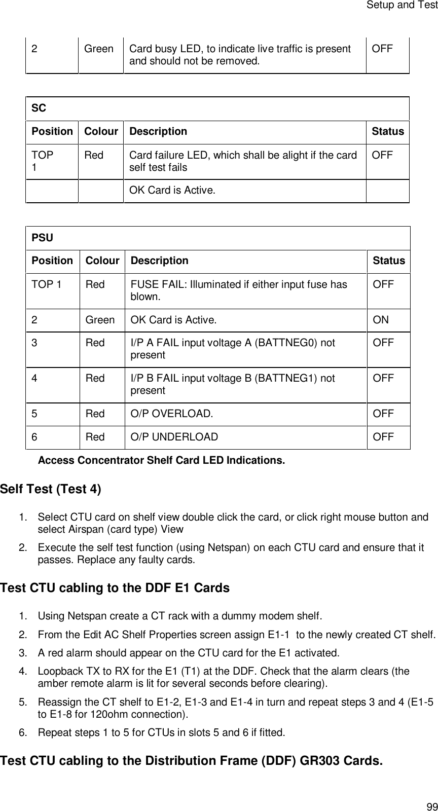
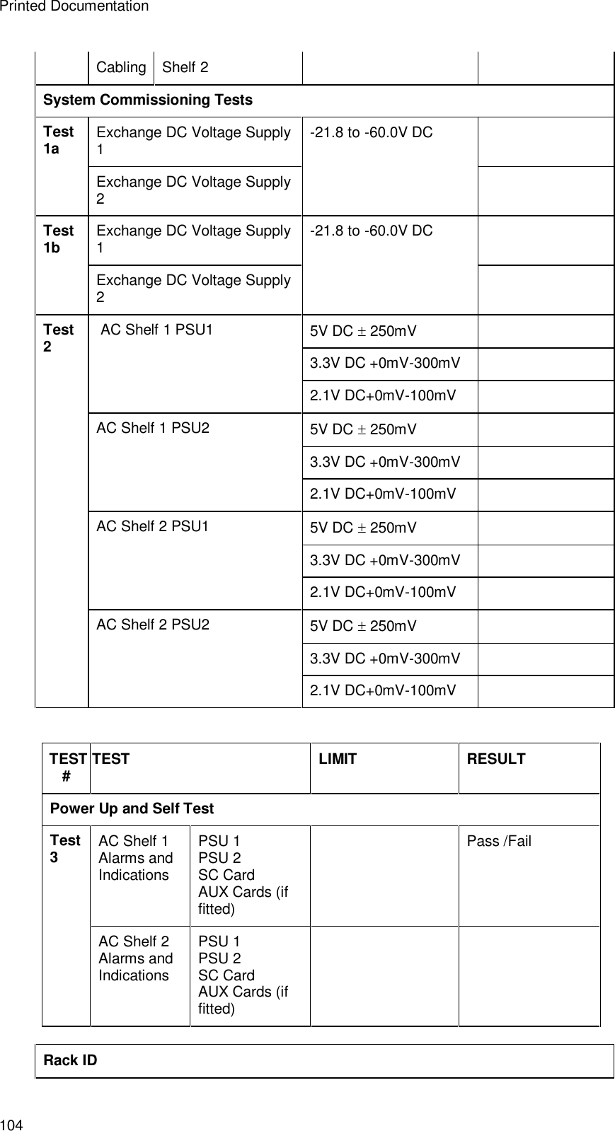
![Setup and Test 139 attenuators c Power meter reading with coupler d Difference between readings e Coupler loss if [c] is greater than [b] then subtract [d] from [a] if [c] is less than [b] then add [d] to [a] Table 2 11. Populate the table below with values obtained from calibrated components and planned levels to calculate/determine overall path loss and required ST output power and hence required power meter reading. RF Channel No: Cable Loss(1) Coupler loss loss.(2) RF Section Loss Antenna- CT( DACU RF Module).(3) Sub Total (4) = 1+2+3 Required CT RX Level (5) See table 1 above. DACU RF Power (6)=4+5 RF Section Loss Antenna - Power Meter (7) Power Meter (8) = 6-7 Table 3 12. Make the test ST transmit by sending the following LAT commands from a terminal emulator connected to the DACU TE<space> 0<space> 4<space> 59 (this code sets the uplink modulation rate for the ST for other required modulations replace the 59 with the session ids shown in table 1 above and should be set to the maximum modulation rate required) FP <space>channel number (in decimal) W<space> 0400003C 13. The terminal emulator should receive 0000000B for the uplink if the ST has acquired a link. 14. On the AS4020 top panel go to Top Menu >Setup Menu >RF Menu>RX Sensitivity 15. Set RX gain by increasing/decreasing the value of RX sensitivity to achieve required ST o/p level calculated as ( 8) in the table above for the required RX Level measured on the power meter. 16. Record the value set in the test results Link check 1. Enable the equalizer by typing the following LAT commands ADE 1 10 (this enables the downlink channel equalizer and it should converge within 10 seconds) ADS (this command displays the equalizer stats). When the equalizer is adapting the stat reports Enabled = 1 Converged = 0 When the equalizer is adapting the stat reports Enabled = 0 Converged = 1 (the 0 for](https://usermanual.wiki/Airspan-Communications/AS4020CT-PCS/User-Guide-446583-Page-143.png)