Airspan Communications AS4020CT-PCS AS4020 Central Terminal PCS Basestation User Manual
Airspan Communications Limited AS4020 Central Terminal PCS Basestation Users Manual
Users Manual

605-0000-593
AS4000 / AS4020 Base Station
Installation and Commissioning
Release 7.30
© 2004 Airspan Networks Inc
iii
Table Of Contents
Installation.............................................................................................................................1
Overview AS4000...........................................................................................................1
Overview AS4020...........................................................................................................3
Preparation ....................................................................................................................4
Rack Installation ................................................................................................................7
Rack Layouts .................................................................................................................7
Rack Layouts ...............................................................................................................11
Rack Installation...........................................................................................................13
DC Power and Alarm Cabling.......................................................................................15
AS4000 AC Rack Cabling and Wiring ..............................................................................20
AC Rack E1 Cabling 75 ohm ........................................................................................20
AC Rack E1 Cabling 120 ohm ......................................................................................25
AC Rack T1 Cabling.....................................................................................................31
PTU to Host Cabling.....................................................................................................33
AC Rack Labeling.........................................................................................................34
Interface Connections...................................................................................................35
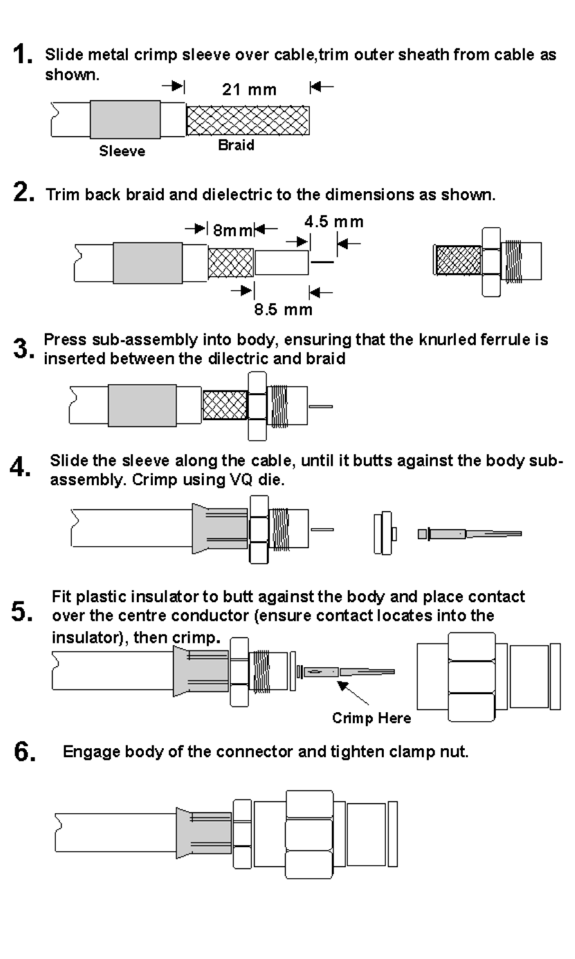
BNC Terminations to Coax...........................................................................................38
Type 43 Terminations to Coax......................................................................................39
Access Concentrator Card Installation..........................................................................41
AS4000 CT Shelf Cabling and Wiring...............................................................................45
Central Terminal Rack E1 Cabling 75 ohm ...................................................................45
CT Rack E1 Cabling 120 ohm ......................................................................................49
CT Rack T1 Cabling .....................................................................................................53
Baseband connections between CT and Expansion Racks...........................................56
Expansion Rack Cabling .....................................................................................................57
Central Terminal Expansion Rack Cabling .......................................................................57
75 Ohm Connections .......................................................................................................58
120 Ohm Connections .....................................................................................................58
Antenna Configurations................................................................................................60
Interface Connections...................................................................................................65
CT Rack Labelling........................................................................................................68
BNC Terminations to Coax...........................................................................................69
Type 43 Terminations to Coax......................................................................................70
Central Terminal Card Installation.................................................................................72
AS4020 CT Shelf Installation and Cabling........................................................................80
Shelf Connections........................................................................................................80
AS4020 Shelf Installation upgrade into AS4000 Rack...................................................82
Adding one AS4020 shelf to existing rack.....................................................................85
Adding two AS4020 shelves to existing rack.................................................................86
Adding three AS4020 shelves to existing rack...............................................................87
Adding four AS4020 shelves to existing rack ................................................................88
Adding two AS4020 with two AS4000...........................................................................89
AS4020 Interface Connections .....................................................................................90
Setup and Test....................................................................................................................91
System Testing ............................................................................................................91
AS4000 AC Setup and Test .............................................................................................92
Access Concentrator: Turn-Up and DC measurements.................................................92
Setting Up the Access Concentrator .............................................................................95
Access Concentrator Rack Commissioning Test Results ............................................102
AS4000 CT Setup and Test ...........................................................................................107
Turn-Up and DC measurements.................................................................................107
Commissioning the Central Terminal ..........................................................................109
Measuring Central Terminal TX Power .......................................................................115
Procedure in case of card boot-up failure....................................................................120
Setting RX sensitivity using DACU 2.0-2.3GHz & 3.4-3.6GHz Band............................121
Setting RX Sensitivity without DACU ..........................................................................123
BER Test....................................................................................................................125
Printed Documentation
iv
Setting the System into Service..................................................................................127
AS4020 CT Setup and Test ...........................................................................................128
AS4020 Menu Map.....................................................................................................128
AS4020 error messages.............................................................................................130
Set Traffic/Management Ports....................................................................................131
Set NMS Menu...........................................................................................................132
Set TX Power.............................................................................................................133
Set RX sensitivity using a DACU without Calibrated Coupler ...................................... 137
Connecting the DACU ................................................................................................141
Set RX Sensitivity without a DACU.............................................................................144
Packet System Testing...............................................................................................148
Voice Option Testing..................................................................................................155
Central Terminal Rack Commissioning Test Results...................................................156
General.............................................................................................................................163
Customer Material Repair and Return Procedures......................................................163
Repair and Return Procedure............................................................................................165
Repair Charges.................................................................................................................170
Return & Repair Tag .........................................................................................................171
Packing and Shipment.......................................................................................................173
Specifications.............................................................................................................176
Copyright Information .................................................................................................178
Contact Information ....................................................................................................179
Problems with this Guide............................................................................................180
Document Purpose.....................................................................................................181
Warnings and Cautions ..............................................................................................182
Issue Status ...............................................................................................................184
Glossary............................................................................................................................185
Index.................................................................................................................................189

1
Installation
Overview AS4000
AS4000 System
The system uses Point-to-Multipoint digital radio links between the individual customer's
premises and the carriers local "point of presence" typically the Local Exchange premises. If
greater flexibility or range is required, the network radio equipment can be located in another
suitable building or wayside cabinet.
Printed Documentation
2
Installation
3
Overview AS4020
AS4020 System
The system uses Point-to-Multipoint digital radio links between the individual customer's
premises and the carriers local "point of presence" typically the Local Exchange premises.
If greater flexibility or range is required, the network radio equipment can be located in
another suitable building or wayside cabinet.

Printed Documentation
4
Preparation
Preparatory Tasks
Installation Tools and Equipment
The following lists of tools and equipment are required to successfully install and test the
AS4000 Access Concentrator Racks.
Required Tools
Combination Spanners: 8 mm, 13 mm, 17 mm, & 19 mm.
Spirit Level: 18 inch.
Pozidrive: No 1 x 75 mm.
No 2 x 100 mm
;No 3 x 150 mm.
Screwdriver, flat blade: 3 mm x 100 mm.
Screwdriver, flat blade: 5.5 mm x 100 mm.
Screwdriver, flat blade: 8 mm x 150 mm.
Hammer, Ball Pein: 1lb.
Drill Bits, Masonry: 11 mm, 12 mm, 13 mm.
Ratchet Crimp Tool for red, blue and yellow insulated crimps.
Crimp Tool type 6A with VQ dies for co-ax connectors and optionally Type 43
connectors
Cordless Drill/Driver.
Required Equipment
Description Recommended Model Quantity
1 Digital Multimeter Fluke 77 or similar 1
2 50 ohm Termination 15W Suhner 6515.17.A 2
3 Test Lead for Management Port Airspan proprietary item 1
4 RF Power Meter Amritsu Sitemaster 400A or
Marconi 6970 1
5 Power Sensor Amritsu 560-7N50B or
Marconi 6932
6 Sensor 30dB 5W attenuator for use
with Amiritsu Power Sensor HP8491 N-type 1
7 DA Commissioning Unit and
associated cables Airspan proprietary item 1
Site Readiness
Verify that the site is ready for the installation of the CT Racks.
This preparation will have been covered by a site survey conducted by Airspan Networks
or by a survey form completed by the customer. The survey will include a site plan of the
facility identifying the floor layout, power outlets, distribution boxes, and cabling runways.
A sketch showing the rack support arrangements showing the exact positions of the
mounting points on the rack with dimensions, and typical overhead ironwork provision
should be included.
Inspect the site, and particularly the equipment room, before unloading or unpacking the
equipment to ensure the following:
Installation
5
Air conditioning is installed and funtional (if required to maintain room environment).
Adequate grounding is provided.
Access to the equipment room will be adequate for normal handling and movement.
Adequate lighting is available for carrying out the installation.
Any non compliance with acceptable standards should be bought to the customers
attention and resolved before proceeding with the installation.
Power Availability
From the site survey, confirm the location of the fuse position for the negative battery
supply and the return point required for each rack. Also locate the fuse position for the
alarm unit power supply.
Site Earth
Confirm the position of the grounding point using the site survey.
Flooring
Ensure that flooring is substantial enough to support the rack and can provide a secure
fixing.
Cable Trays
Verify that cable trays are installed to provide routing to the proper destinations and are of
adequate strength
Delivery Inspection
Upon taking delivery of the equipment consignment, check that the consignment agrees in
all particulars with the consignment delivery documentation (number of boxes,
descriptions, and the contents of boxes, etc.). Any discrepancy or damage must be
reported immediately to ACC for further instructions. In case of severe damage, do not
accept the consignment from the carrier. See Material Return and Repair document for
further details. The equipment is normally shipped as shown below.
If subsequent to the initial shipment incremental upgrades are made to the system the
equipment will be delivered in packaging of size and type suitable for that shipment.
Unpacking Inspection
The contents of each box must be checked against the relevant part lists provided with the
box, for the correct part numbers and quantities, and for damage. Any shortage or
damaged items must be reported immediately to Airspan Networks International Call
Centre for further instructions at the address given in the Contact Information section of
this manual or:
TELEPHONE: +44 (0) 1895 467 467
FAX: +44 (0) 1895 467472
Email: support@airspan.com
Dispose of all unnecessary packaging in a safe manner according to the
customer’s requirements.
During UK working hours, the Airspan Shipping Department can be contacted at:
Tel:+44 1895 467 444 or +44 1895 467 444
Fax:+44 1895 467 438

Printed Documentation
6
Note: It is recommended that one package carton of each type is retained should it be
required to return any faulty or damaged items for repair.

Installation
7
Rack Installation
Rack Layouts
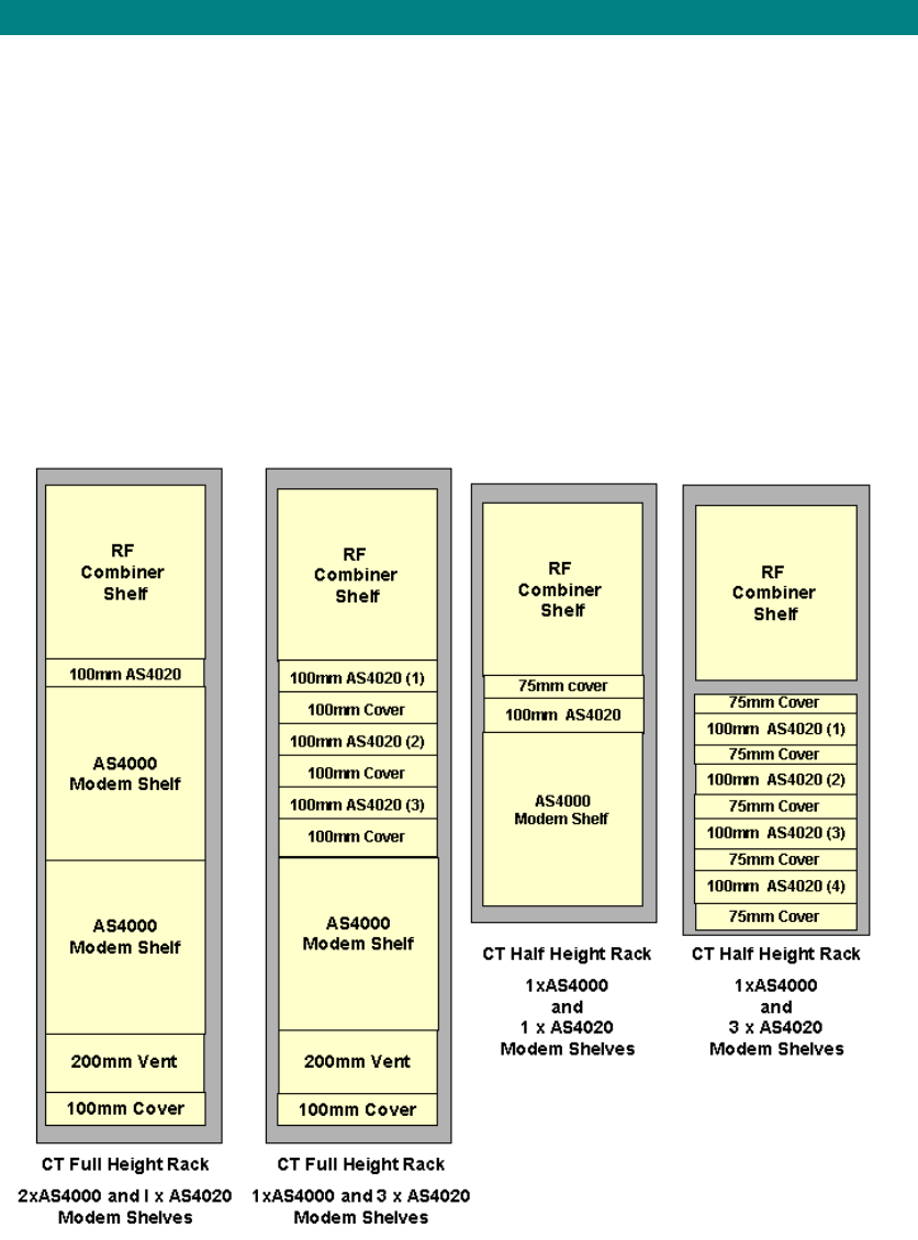
AS4000 Racks
AS4000 Central Terminal and Access Concentrator Racks are produced with the following
layouts:
Access Concentrator
One DA Access Concentrator Shelf and a Fuse and Alarm Panel
Two Access Concentrator Shelves and a Fuse and Alarm Panel
Printed Documentation
8
Central Terminal Demand Assignment System
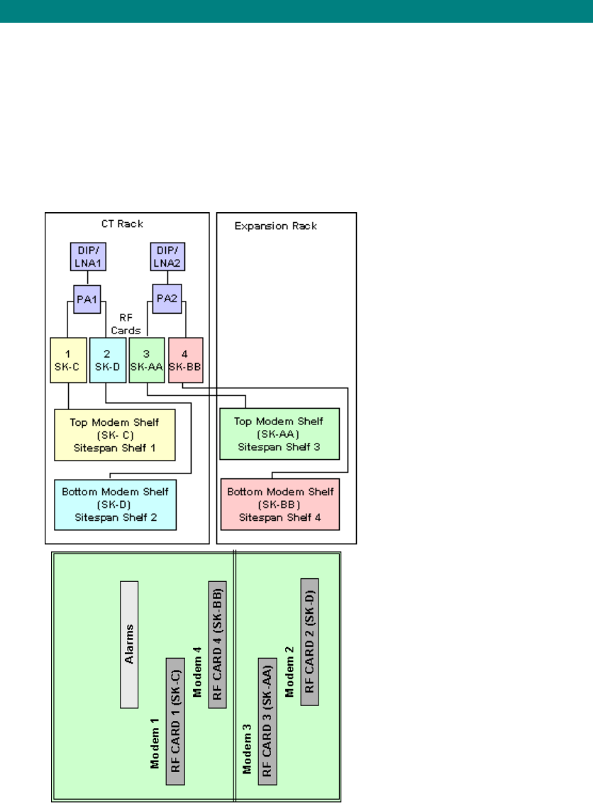
One DA Modem Shelf with RF Combiner Shelf
Two DA Modem Shelves with RF Combiner Shelf
Expansion Rack with one DA Modem Shelf and a Fuse and Alarm Panel. (Connects to
an existing Central Terminal Rack)
Expansion Rack with two DA Modem Shelves and a Fuse and Alarm Panel. (Connects to
an existing Central Terminal Rack)
Installation
9
No of Modem
Shelves Central
Terminal Rack Expansion Rack
1 1 Modem Shelf Not required
2 2 Modem
Shelves Not required
3 2 Modem
Shelves 1 Modem Shelf
4 2 Modem
Shelves 2 Modem Shelves
Integrated Basestation
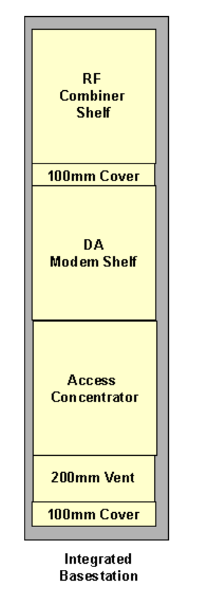
The Integrated Basestation incorporates a Combiner Shelf , Modem Shelf and Access
Concentrator in a full height equipment rack.
Printed Documentation
10
Installation
11
Rack Layouts
AS4020 Racks
AS4020 Central Terminal racks are produced with the following layouts:
Central Terminal Systems using AS4020
Full height rack with RF Combiner Shelf. two AS4000 Modem Shelves and one
AS4020 Modem Shelf
Full height rack with RF Combiner Shelf, one AS4000 Modem Shelves and up to
three AS4020 Modem Shelves
Compact rack with RF Combiner Shelf. One AS4000 Modem Shelf and one AS4020
Modem Shelf
Full height rack with RF Combiner Shelf, up to four AS4020 Modem Shelves
Full height rack with RF Combiner Shelf. two AS4000 Modem Shelves and two
AS4020 Modem Shelves
Full height rack with RF Combiner Shelf. two AS4000 Modem Shelves and two AS4020
Modem Shelves
Printed Documentation
12
Installation
13
Rack Installation
Positioning and Securing Racks
Installing Rack in a Suite
From the site survey, confirm the position of the CT Rack(s). If the racks are to be
positioned in a suite, metalwork will be required to secure it to the overhead structure.
Either a proprietary system or fabricated steelwork will be required - see site survey.
Manoeuvre the racks into position.
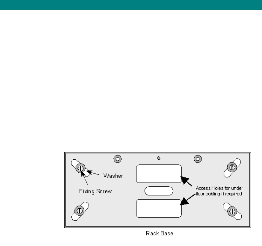
Securing Rack Base
Using the base of the rack as a template, mark the floor locating positions through the
cutouts in the Rack Frame. Using a 13mm diameter drill bit, drill four holes to a depth of
approximately 25mm. Position the rack over the four holes and screw the four (supplied)
M12 screws through washers to secure the rack base. If the rack is cabled from under the
floor the access holes are required through the floor beneath the rack base.
Securing Rack Base
Warning: These screws are provided as locating pins only and must be used in
conjunction with the overhead steelwork and not as the only method for securing the rack.
Temporarily secure the rack to adjacent racks or steelwork until the overhead support is in
place.
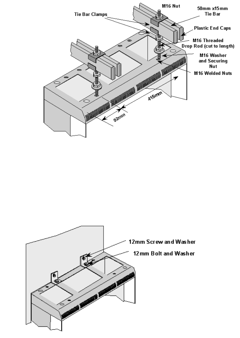
Securing the rack using overhead Ironwork
Assemble the overhead steelwork as required and secure the rack to the overhead
structure using suitable fixings in compliance with local requirements. Remove all burrs
and sharp edges.
Printed Documentation
14
Typical Overhead Ironwork Support
Note: In installations where threaded droprods in excess of 500mm are employed it may
be necessary to provide additional support bars to ensure rigidity of the support structure.
Securing a Rack to a Wall
If the rack is to be positioned against a wall, attach two right-angled wall brackets to the
top of the rack and finger tighten with the provided M12 screws.
Manoeuvre the racks into position against the wall. Join the racks together with 12mm
nuts and bolts placed through the holes at the top and bottom of the side panels and mark
the wall through the holes in the top brackets.
Securing Rack to a Wall
Using an 11mm. drill bit, drill holes in the wall to a depth of 75mm and fit masonry plugs.
Fix the hex head screws through the brackets and finger tighten. Check that the rack is in
the correct position and tighten all fixings.
Attention should be paid to the fabric of the wall. Where possible, drill directly into the
brick and not into mortar. With panelled or partitioned walls, instruction should be taken
locally as to how the rack is to be secured. See site survey.
Follow the procedure for the rack base as described above.
Installation
15
DC Power and Alarm Cabling
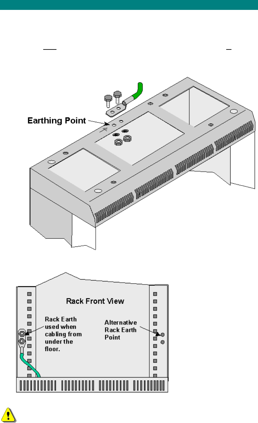
Rack Earthing
Using the site survey, locate the building central [safety] grounding point. Run an earth cable
rated at 30A to each rack and connect it to the centre earth stud located at the top or at the
side of the rack. (only one external earth per rack) See illustrations below. These points are
labelled with the IEC Earth symbol.
Rack earthing at top
Rack earthing at base
Other external safety earth connections must not be made to the rack.
Printed Documentation
16
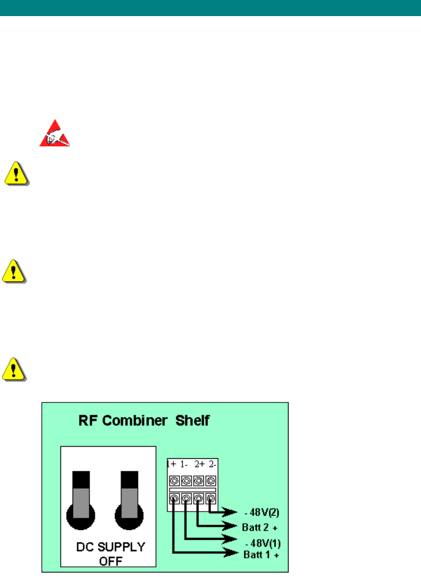
Terminate the battery feed and return cables at the isolator/fuse positions, and ensure that
the AC rack is isolated until the commencement of commissioning tests.
DC Power
The cables for the negative DC battery feeds, the 0V returns and the Rack Ground are
detailed in. Should local requirements specify otherwise, it is acceptable for cables of other
colours to be used, however, under no circumstances should the cable sizes be less than that
specified in. The length of the cable supplied will be detailed in the site survey. Separate DC
sources are desirable for maximum protection.
Function Colour Min. Cable Size
Negative Battery Feed -36V
to -60V DC Blue 10 AWG; 6.0mm2
Zero Volt Positive Battery
Return Black 10 AWG; 6.0mm2
Rack Ground Green/Yellow 8AWG; 10.0mm2
DC Power Cables.
This equipment requires a negative Supply. Ensure that the +ve volt line is connected
to ground or that the supply is floating. The –ve battery feed should not be connected to
ground or zero volts under any circumstances.
The maximum DC input should not exceed 60 Volts. Voltages in excess of this are
considered hazardous.
Note 1: Do not insert fuses until instructed to do so in the commissioning stage of installation.
Note 2: If the equipment is installed according to EN 60950 §1.7.9, there should be available
a single disconnect device that isolates the whole equipment., A double-pole external
isolating switch should be provided to isolate the two supplies and should be wall mounted in
the locale of the rack. A label should be included on the unit to direct the user to use the
external isolator for isolation.
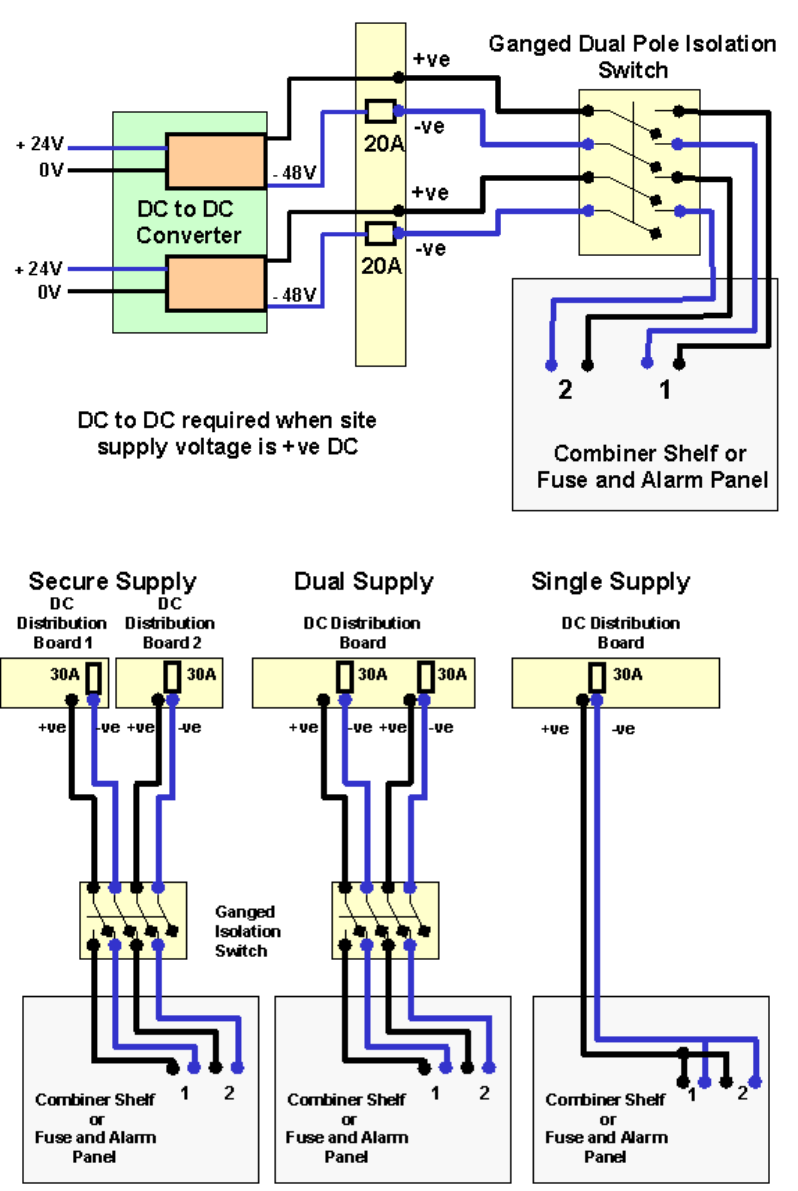
The Access Concentrator and Central Terminal Shelves are designed to operate from a -48V
DC supply. In installations where the nominal supply voltage is +24V DC a DC to DC
converter is needed to provide the -48V supply see the schematic diagram below. The DC to
DC converter must be rated at 20 amps or greater at -48V DC
Installation
17
Power Supply Configurations
Three alternative methods are possible to connect the DC supply to the rack.
Secure Supply: This is the preferred method as it provides DC from different sources
giving greater resilience of supply than the other methods. (see diagram above and note
2 below) From each Distribution Boards (DB) run and tie in a negative battery feed and
a zero volt return to a Dual Pole Isolating switch and then from the isolating switch to the
AC/CT rack installed. These supplies should be rated at 30A. Power cables must be run
and tied separate from signal cables.
Printed Documentation
18
Dual Supply: Both feeds are fed from the same Distribution Boards (DB) and separately
fused so that in the event of one fuse failing the rack is supplied via the other fuse. Run
and tie in two negative battery feeds and a two zero volt returns from the Distribution
Board to a Dual Pole Isolating switch and then from the isolating switch to the to the
AC/CT rack installed. These supplies should be rated at 30A. Power cables must be run
and tied separate from signal cables. (see diagram above and note 2 below).
Single Supply: Is the least preferred option as a blown fuse causes the total loss of
supply to the rack but because there is only one supply the fuse can act as an isolation
point and there is no need for a separate isolation switch as required on the other
options. Run and tie in a negative battery feed and a zero volt return from the Distribution
Boards to the AC/CT rack installed. The two inputs to the Combiner Shelf/Fuse and
Alarm Panel should be looped together as shown in the diagram above. This ensures
that the alarms on the PSU are extinguished when a supply is present.
From the site survey confirm the location of the isolator for the negative battery feed points;
then ensure that the supply is isolated. If the location is remote from the AC Rack, take
appropriate action to ensure that the supply is not inadvertently reconnected. This may
include locking OFF an isolator, removing fuses and ensuring that replacement fuses are not
easily installed. Provide a label at the AC Rack to indicate the location of the isolator or fuse
positions mentioned above.
To provide security of supply two separate Distribution Boards (DB) should be used to supply
DC to each rack (see note 2 below) Run and tie in a negative battery feed and a zero volt
return to the AC/CT rack installed from the DB. Run and tie in a second negative battery feed
and a zero volt returns to the AC/CT rack installed from a second DB, if a second distribution
board is available. If only one source of supply is available the both supplies may be run from
the same DB These supplies should be rated at 30A. Power cables must be run and tied
separate from signal cables.
DC Cabling Central Terminal Modem Rack/Integrated Basestation
Run the DC cables through the top right hand side of the rack, loosen the screws on the
Combiner Shelf and slide the screen to the right. Place the DC cables behind the screening
and though to the connection block at the lower right of the Combiner Shelf. Return the
screen to its original position. Re-tighten the Combiner shelf screws.
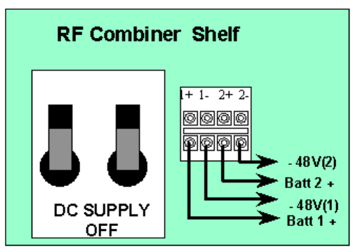
Trim cables and strip 7mm to insert into the termination block. Terminate the cables on the
Combiner Shelf at the appropriate connection points. The negative supplies go to Termination
Block 2 & 4. The positive battery returns go to 1 & 3.
DC Termination on The Combiner Shelf.
DC Termination on Fuse and Alarm Panel (AS4000 Access Concentrator
and AS4000 Expansion Rack)
Run the DC cables through the top left hand side of the rack, into the fuse and alarm panel.
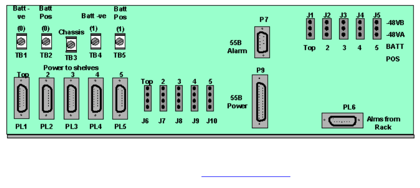
Installation
19
Remove clear plastic cover protecting the DC input terminals. Trim cables and strip 7mm.
Crimp a spade terminal or terminal ring onto the wire and attach to terminals inside the Fuse
and Alarm panel at the appropriate connection points. The negative supplies go to
Termination Block 1 & 4. The positive battery returns go to 2 & 5. Replace clear plastic cover
protecting the DC input terminals.
DC Termination on Fuse and Alarm Panel.
Station Alarm Connection
For Power and Alarm wiring on AS4020 see 'AS4020 Installation'
Printed Documentation
20
AS4000 AC Rack Cabling and Wiring
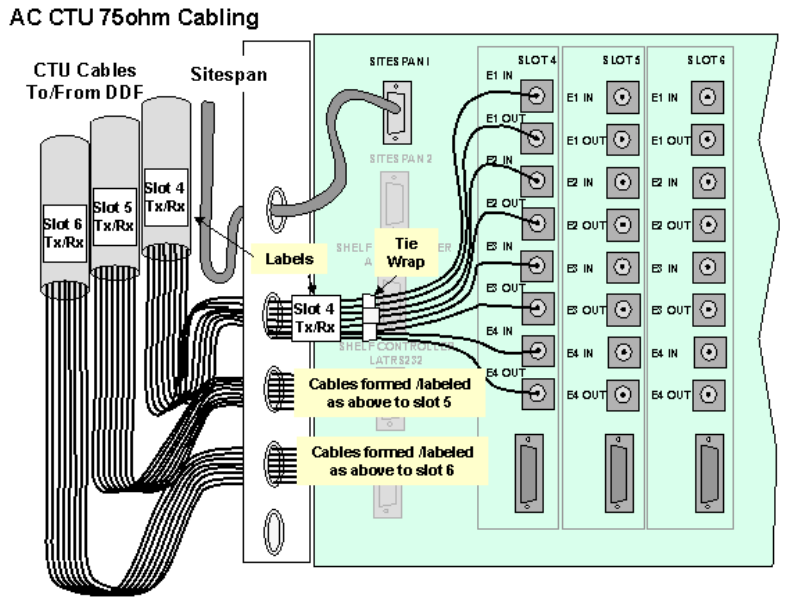
AC Rack E1 Cabling 75 ohm
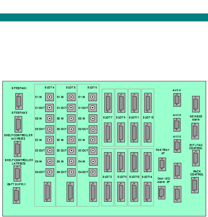
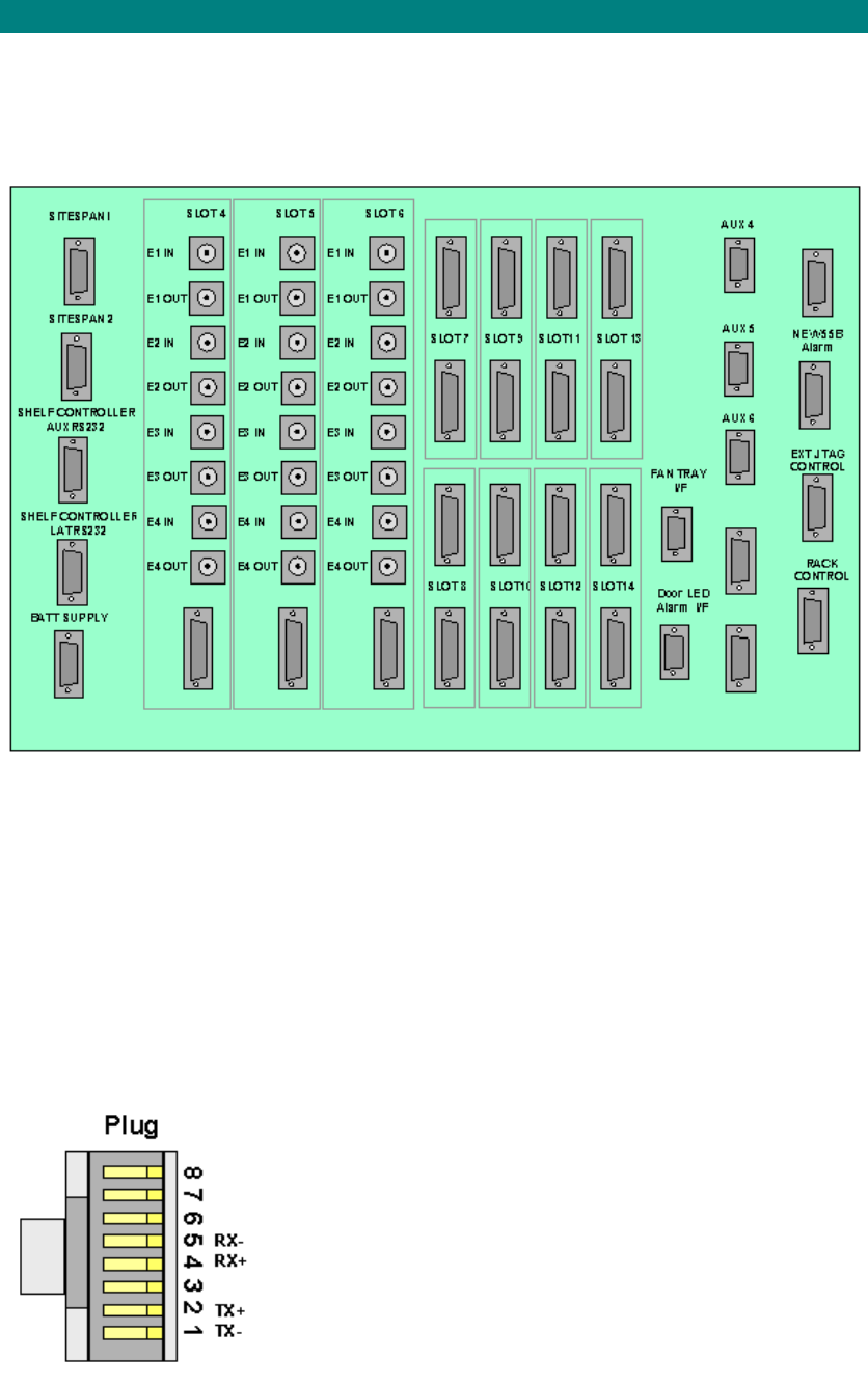
Access Concentrator Interface Panel
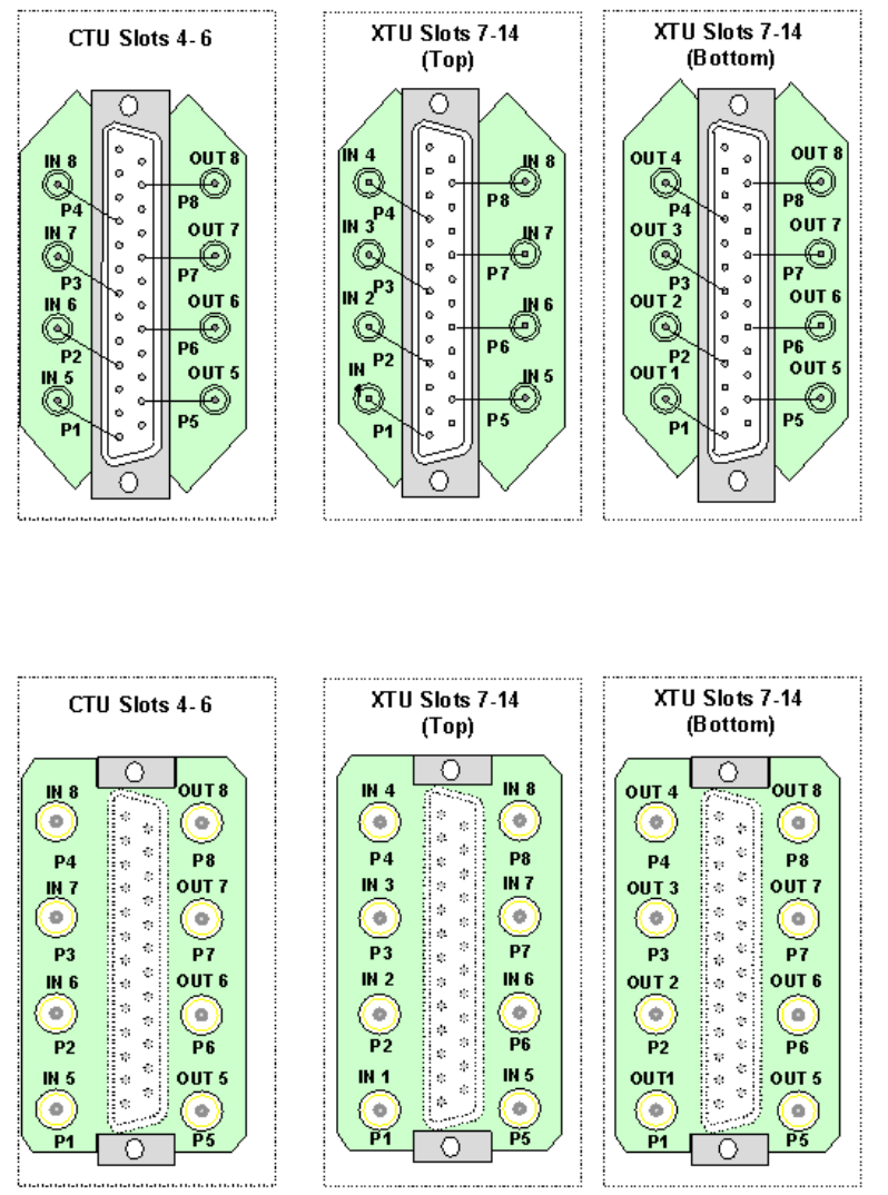
All cabling to the access concentrator connects to the interface panel. Slots 4,5 and 6 can be
used for 75ohm and 120ohm connections. Slots 7-14 is used for 120ohm connections each
slot will support up to 8 E1 connections.
Access Concentrator Interface Panel (1026 Board)
Specification: In installations with 75ohm cabling Braided screened, 75ohm, Coaxial Cable
is to be used for interconnection between the AC shelf the DDF and switch/channel bank.
a) E1 Cabling (CT Link)
From the site survey, confirm the location of the Digital Distribution Frame (DDF) if a DDF is
to be used or the CT links if the E1 feeds are fed direct to the equipment. The length of E1
feeds should not exceed 100 metres.
Note: This must be a SELV port of an EN 60950 approved product.
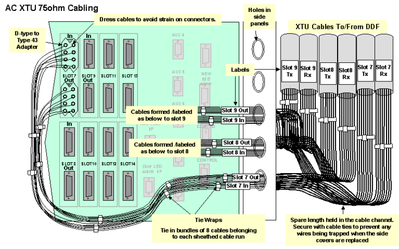
Run the E1 cables from the AC shelf to the allocated positions on the DDF. (8 cables per CTU
in normal working,up to 3 CTUs per shelf.).
In partial equipped installations it may be appropriate to run enough cables to cater for a
complete rack of equipment. This reduces the need to disturb original installation when
adding additional equipment.
Feed the E1 cables through the top hole on the left hand side of rack side of the rack, and
down the channel at the side of the rack.
Identify and label each cable at both ends as well as the DDF/Backhaul positions.
Terminate all cables with BNC co-axial connectors (or it is possible to fit type 43 and adapters
if BNC connectors are not available).
Installation
21
b) E1 Cabling (Switch Link)
From the site survey, confirm the location of the Digital Distribution Frame (DDF) if a DDF is
to be used or the Switch if the E1 feeds are fed directs to the equipment. The length of E1
feeds should not exceed 250 metres.
Note: This must be a SELV port of an EN 60950 approved product.
Run the E1 cables from the AC shelf to the allocated positions on the DDF. In partial
equipped installations it may be appropriate to run enough cables to cater for a complete rack
of equipment. This reduces the need to disturb original installation when adding additional
equipment.
Feed the E1 cables through the top hole on the most convenient side of the rack, and down
the front of the rack.
Identify and label each cable at both ends as well as the DDF/Backhaul positions.
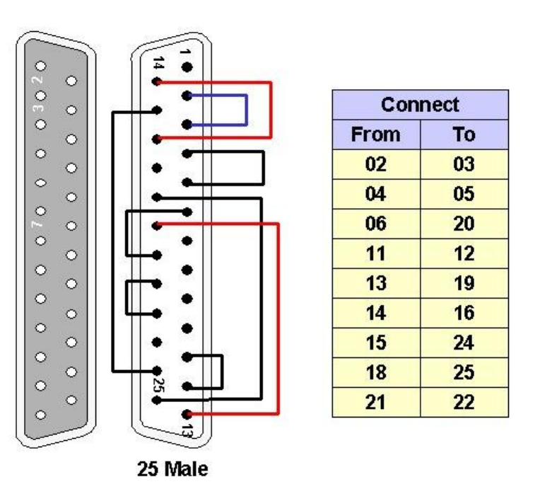
a. Type 43 to 25wayD-type adaptors to the backplane sockets and terminate all cables with
Type 43 connectors (75ohm ) and fit according to the figure below .
Printed Documentation
22
Type 43 Backplane Adapter
b. Siemens 1.5/6.5 Connector. Fit Siemens 1.5/6.5 Connector to 25way D-type adapters
303-1139-900 to the backplane sockets and terminate all cables with Siemens 1.5/6.5
connectors (75ohm ) and fit according to the figure below.
Installation
23
Typical 75ohm DDF Layout
Printed Documentation
24
Installation
25
AC Rack E1 Cabling 120 ohm
Access Concentrator Interface Panel
All cabling to the access concentrator connects to the interface panel. Slots 4,5 and 6 can be
used for 75ohm and 120ohm connections. Slots 7-14 is used for 120ohm connections each
slot will support up to 8 E1 connections.
Access Concentrator Interface Panel (1026 Board)
120 ohm Cabling Specification
In installations with 12Oohm cabling Double screened, 120Ohm, 8 twisted pairs. The overall
screen should be screened with a foil AND 90% coverage tinned copper braid is to be used
for interconnection between the AC shelf, the DDF and switch/channel bank.
a) E1 Cabling (CT Link)
From the site survey, confirm the location of the Digital Distribution Frame (DDF) if a DDF is
to be used or the CT links if the E1 feeds are fed direct to the equipment. The length of E1
feeds should not exceed 100 metres.
Note: This must be a SELV port of an EN 60950 approved product.
Run the E1 cables from the AC shelf to the allocated positions on the DDF. (8 Pairs per CTU
in normal working,up to 3 CTUs per shelf.).In partial equipped installations it may be
appropriate to run enough cables to cater for a complete rack of equipment. This reduces the
need to disturb original installation when adding additional equipment.
Feed the E1 cables through the top hole on the left hand side of rack side of the rack, and
down the channel at the side of the rack. Identify and label each cable at both ends as well as
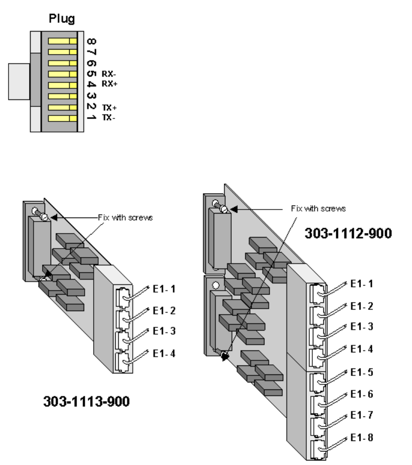
the DDF/Backhaul positions. Terminate all cables with RJ45 plugs and fit adapter 303-1112-
900 (See RJ45 terminations below) or use D-type connectors (See D-type terminations
below) at the rack .Terminate as appropriate at the DDF.
b) E1 Cabling (Switch Link)
From the site survey, confirm the location of the Digital Distribution Frame (DDF) if a DDF is
to be used or the Switch if the E1 feeds are fed directs to the equipment. The length of E1
feeds should not exceed 250 metres.
Printed Documentation
26
Note: This must be a SELV port of an EN 60950 approved product.
Run the E1 cables from the AC shelf to the allocated positions on the DDF. In partial
equipped installations it may be appropriate to run enough cables to cater for a complete rack
of equipment. This reduces the need to disturb original installation when adding additional
equipment.
Feed the E1 cables through the top hole on the most convenient side of the rack, and down
the front of the rack. Identify and label each cable at both ends as well as the DDF/Backhaul
positions. Terminate all cables with RJ45 plugs and fit adapter 303-1113-900 (See RJ45
terminations below) or use D-type connectors (See D-type terminations below) at the rack
.Terminate as appropriate at the DDF.
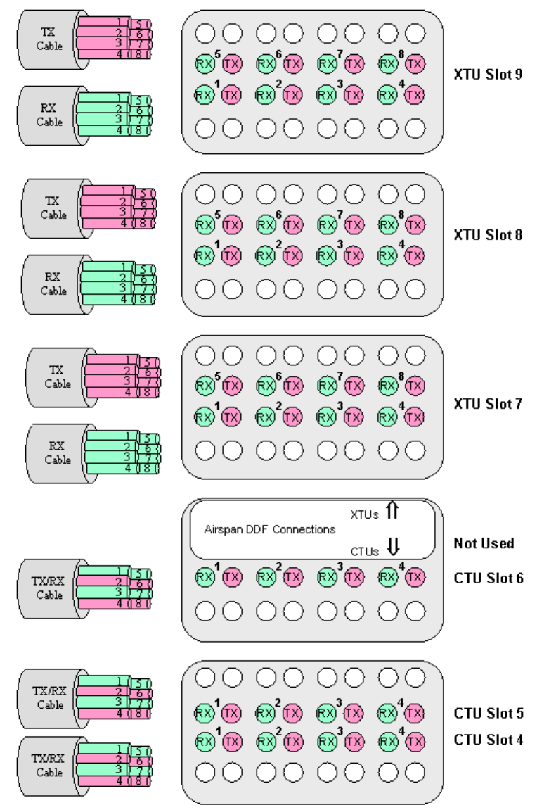
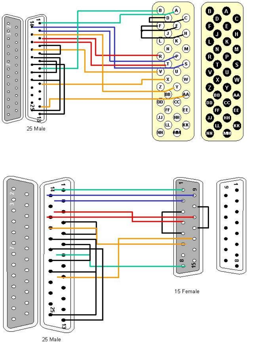
RJ45 Terminations
Terminate all cables with RJ45 connectors at the rack and as appropriate at the DDF.
RJ45 connector termination
Fit the RJ45 adapter 303-1113-900 (Slots 4,5 and 6) and 303-1112-900 (slots 7-14) and
secure to the Backplane using screws in the top and bottom holes of the adapter.
D-Type Terminations: Terminate all cables with 25 pin D-type connectors (120Ohm )
according to the tables below or fit RJ45 adapter to the D-Type Plugs on the AC Interface
Panel. .
Note:On D-Type connectors the screen connects to pin 13
Installation
27
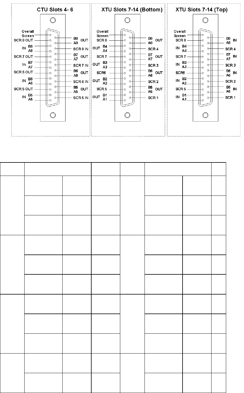
Pair Designation Pin Pair Designation Pin
A1 In 1 A5 Out 15
B1 In 2 B5 Out 16
1
Screen 14
5
Screen 3
A2 In 4 A6 Out 18
A3 In 5 B6 Out 19
2
Screen 17
6
Screen 6
A3 In 7 A7 Out 21
B3 In 8 B7 Out 22
3
Screen 20
7
Screen 9
A4 In 10 A8 Out 24 4
B4 In 11
8
B8 Out 25

Printed Documentation
28
Screen 23 Screen 12
Overall Screen 13
120 ohm connections slots 4-6
Pair Designation Pin Pair
Designation Pin
A1 In 1 A5 Out 15
B1 In 2 B5 Out 16
1
Screen 14
5
Screen 3
A2 In 4 A6 Out 18
A3 In 5 B6 Out 19
2
Screen 17
6
Screen 6
A3 In 7 A7 Out 21
B3 In 8 B7 Out 22
3
Screen 20
7
Screen 9
A4 In 10 A8 Out 24
B4 In 11 B8 Out 25
4
Screen 23
8
Screen 12
Overall Screen 13
120 ohm connections slots 7-14 (In)
Pair Designation Pin Pair
Designation Pin
1 A1 In 1 5 A5 In 15

Installation
29
B1 In 2 B5 In 16
Screen 14 Screen 3
A2 In 4 A6 In 18
A3 In 5 B6 In 19
2
Screen 17
6
Screen 6
A3 In 7 A7 In 21
B3 In 8 B7 In 22
3
Screen 20
7
Screen 9
A4 In 10 A8 In 24
B4 In 11 B8 In 25
4
Screen 23
8
Screen 12
Overall Screen 13
120 ohm connections slots 7-14 (Out)
Pair Designation Pin Pair Designation Pin
A1 Out 1 A5 Out 15
B1 Out 2 B5 Out 16
1
Screen 14
5
Screen 3
A2 Out 4 A6 Out 18
A3 Out 5 B6 Out 19
2
Screen 17
6
Screen 6

Printed Documentation
30
A3 Out 7 A7 Out 21
B3 Out 8 B7 Out 22
3
Screen 20
7
Screen 9
A4 Out 10 A8 Out 24
B4 Out 11 B8 Out 25
4
Screen 23
8
Screen 12
Overall Screen 13
Installation
31
AC Rack T1 Cabling
All cabling to the Access Concentrator connects to the interface panel. Slots 7, 8, and 9 can
be used for T1 CTU connections. Slots 10-14 are used for T1 XTU connections each slot will
support up to 8 T1 connections. (Exceptionally slots 4, 5, and 6 can be used for XTU
connections using an adapter 303-1113-900 connected to the D- type below the BNCs for the
relevant slot. Only T1 5-8 are available for T1 connections.) Slots 8 and 9 can also be used
for XTU’s but it is normal to reserve these for future CTUs if possible.
Cabling Specification
In installations Cat 5 FTP screened (foil & braid) twisted pair should be used.
a) T1 Cabling (CT Link)
From the site survey, confirm the location of the Digital Distribution Frame (DDF) if a DDF is
to be used or the CT links if the T1 feeds are fed direct to the equipment. The length of T1
feeds should not exceed 100 metres.
Run the T1 cables from the AC shelf to the allocated positions on the DDF. (8 Pairs per CTU
in normal working, up to 3 CTUs per shelf.). In partial equipped installations it may be
appropriate to run enough cables to cater for a complete rack of equipment. This reduces the
need to disturb original installation when adding additional equipment.
Feed the T1 cables through the top hole on the left hand side of rack side of the rack, and
down the channel at the side of the rack.
Identify and label each cable at both ends as well as the DDF/Backhaul positions.
Terminate all cables with RJ45 connectors at the rack and as appropriate at the DDF.
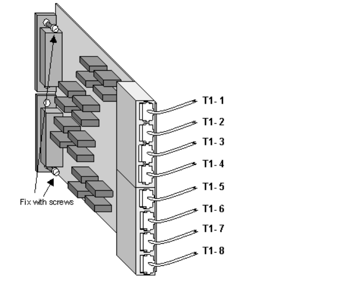
T1 RJ45 connector termination
Printed Documentation
32
Fit the RJ45 adapter 303-1112-900 and secure to the Backplane using screws in the top and
bottom holes of the adapter.
RJ45 adapter 303-1112-900
b) T1 Cabling (Switch Link)
From the site survey, confirm the location of the Digital Distribution Frame (DDF) if a DDF is
to be used or the Switch if the T1 feeds are fed directs to the equipment. The length of T1
feeds should not exceed 100 metres.
Run the T1 cables from the AC shelf to the allocated positions on the DDF. In partial
equipped installations it may be appropriate to run enough cables to cater for a complete rack
of equipment. This reduces the need to disturb original installation when adding additional
equipment.
Feed the T1 cables through the top hole on the most convenient side of the rack, and down
the front of the rack.
Identify and label each cable at both ends as well as the DDF/Backhaul positions.
Terminate all cables with RJ45 connectors as shown above and fit RJ45 adapter to the D-
Type Plugs on the AC Interface Panel as shown above
Installation
33
PTU to Host Cabling
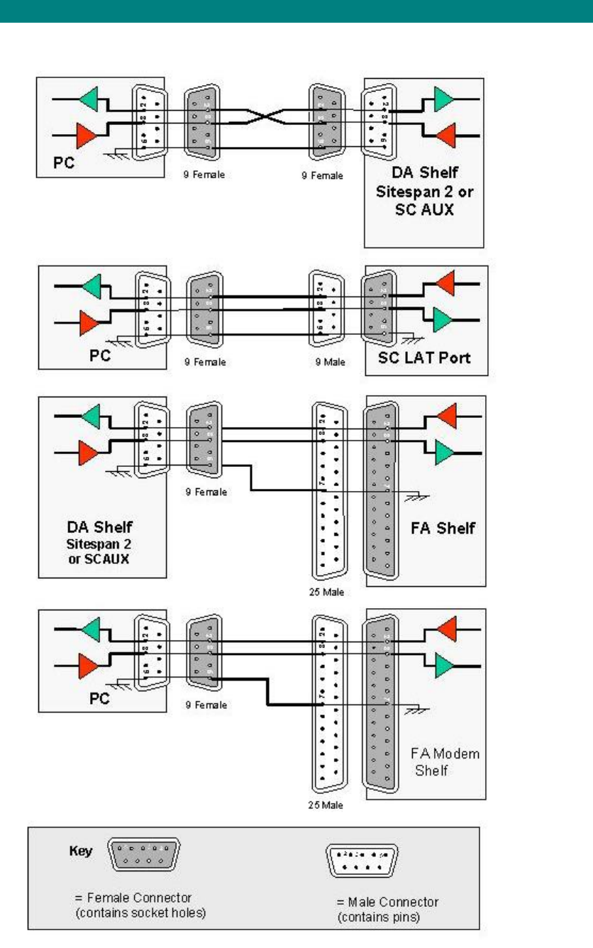
RJ45 to DB25 Adaptor
To connect the 100baseT cable to the AC Shelf interface panel a RJ45 to DB25 adaptor must
be fitted. Fit the RJ45 to DB25 adaptor and screw to the backplane. The RJ45 to DB25
adaptor currently must be connected onto the lower of the two 25-way AC connectors
allocated to each slot (even though the activity lights work if connected to the top).
Patch Cable
A standard Cat 5 Ethernet patch cable with 8-way RJ45 plugs at each end has all pins
connected straight through. The Tx and Rx pairs are pins 1&2 and 3&6. With plug towards
you, cable away from you, pins on the top, pin 1 is on your right. Clearly Tx at one end must
talk to Rx at the other.
A Hub (and Router) Ethernet port will have a built in crossover, often denoted by a ‘X’ printed
on the box, so a PC to a Hub uses a straight through standard patch cable, and so does a
Router to the PTU.
To connect a PC to PC or a PC to PTU (for demo, tests, etc.), use a crossover cable, with Pin
1 to Pin 3 and Pin 2 to Pin 6.
Printed Documentation
34
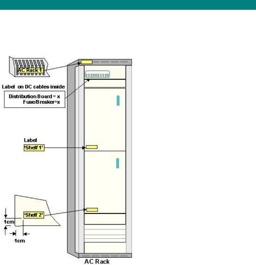
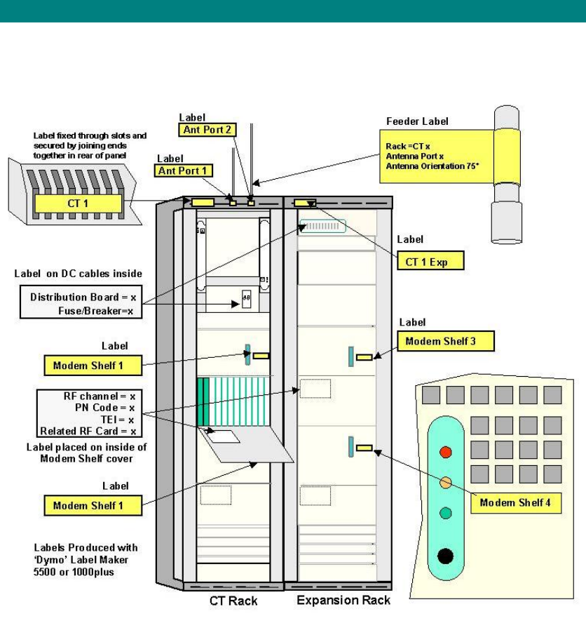
AC Rack Labeling
The racks should be labelled as shown below.
Access Concentrator Rack

Installation
35
Interface Connections
This page contains miscellaneous interface and connector details.

Printed Documentation
36
120 Ohm Interface Connections on DA Access Concentrator Backplane
Interface Adaptor EIA 530 to V35
Interface Adapter EIA 530 to X21
EIA 530 loopback Connector
Installation
37
Printed Documentation
38
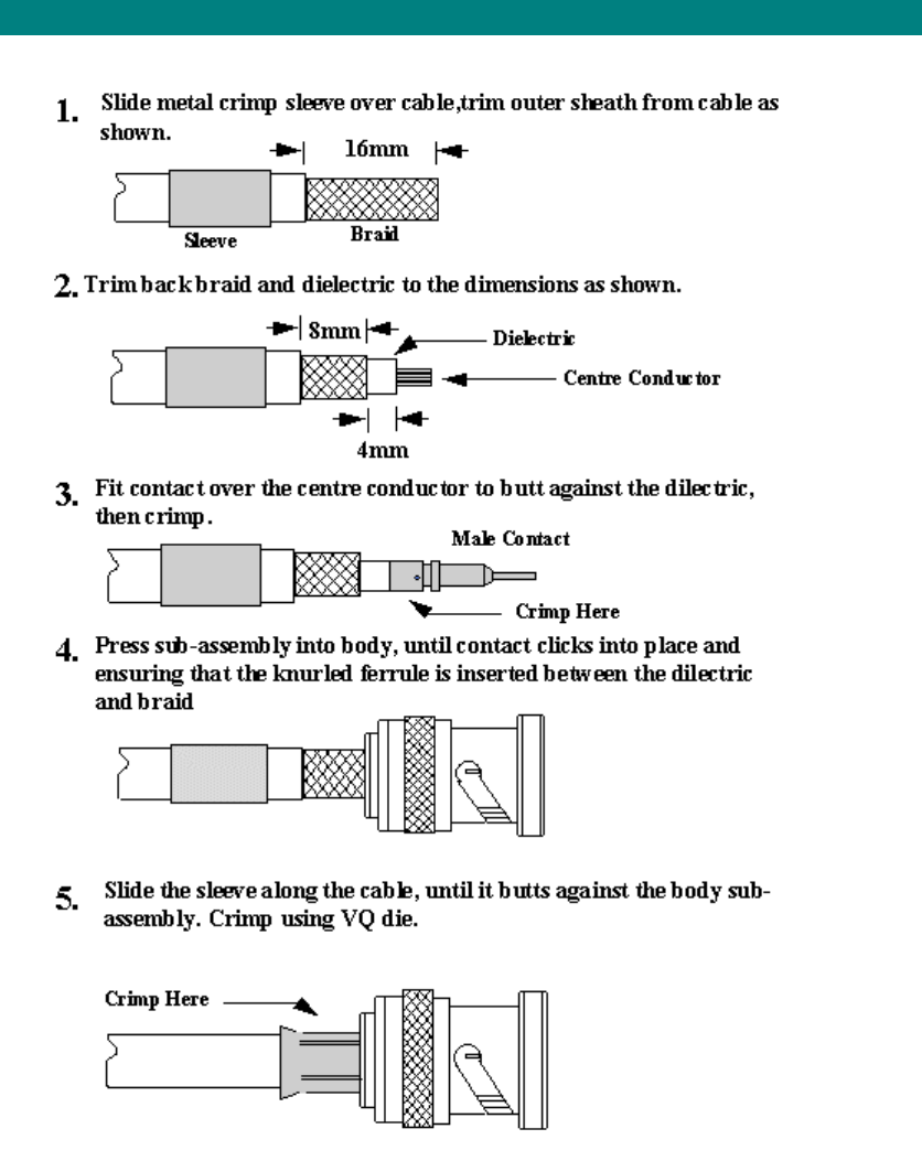
BNC Terminations to Coax

Installation
39
Type 43 Terminations to Coax
Printed Documentation
40
Installation
41
Access Concentrator Card Installation
The AC rack is shipped with shelves fitted to customer requirements and internal cabling
complete.
Warning: Before handling any cards or modules, observe full anti-static precautions.
See Operations an Maintenance Guide
Preliminary
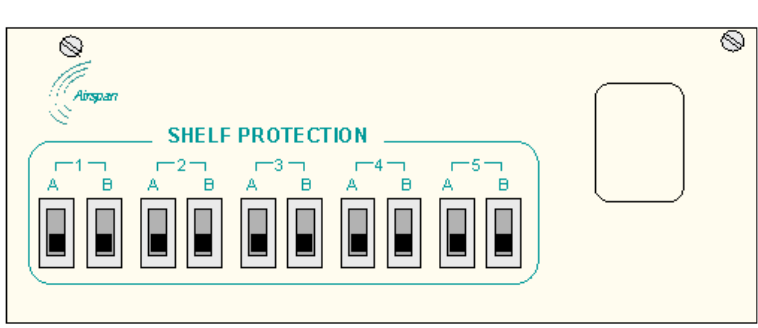
In a new installation ensure that the AC Circuit on the Fuse and Alarm panel are set to the
OFF position (down).
Warning: Isolation of power from the rack is only achieved by ensuring that both circuit
breakers are in the off position.
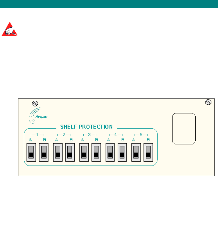
Access Concentrator Rack Fuse and Alarm Panel
Ensure that the end of suite fuses are adequately rated and insert these into the respective
fuse holder positions.
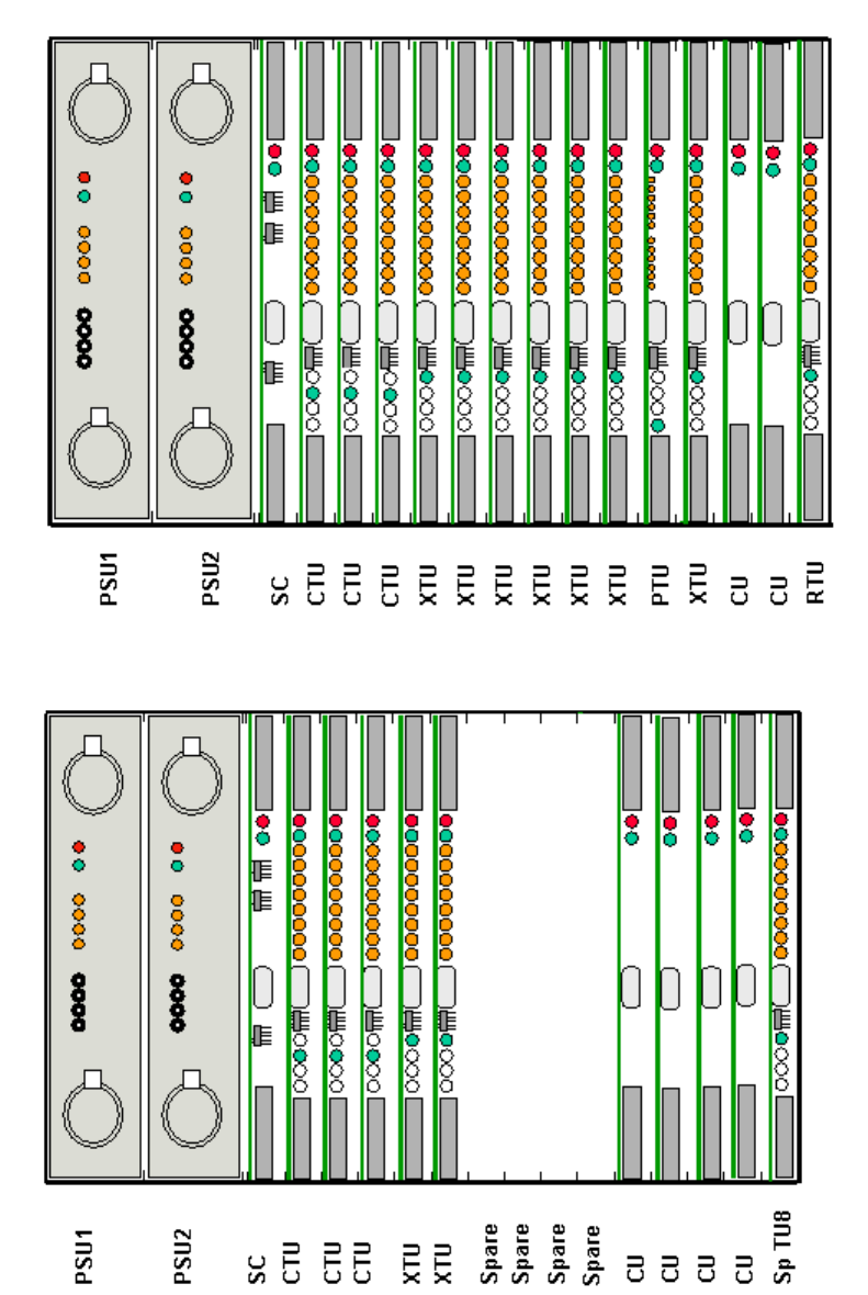
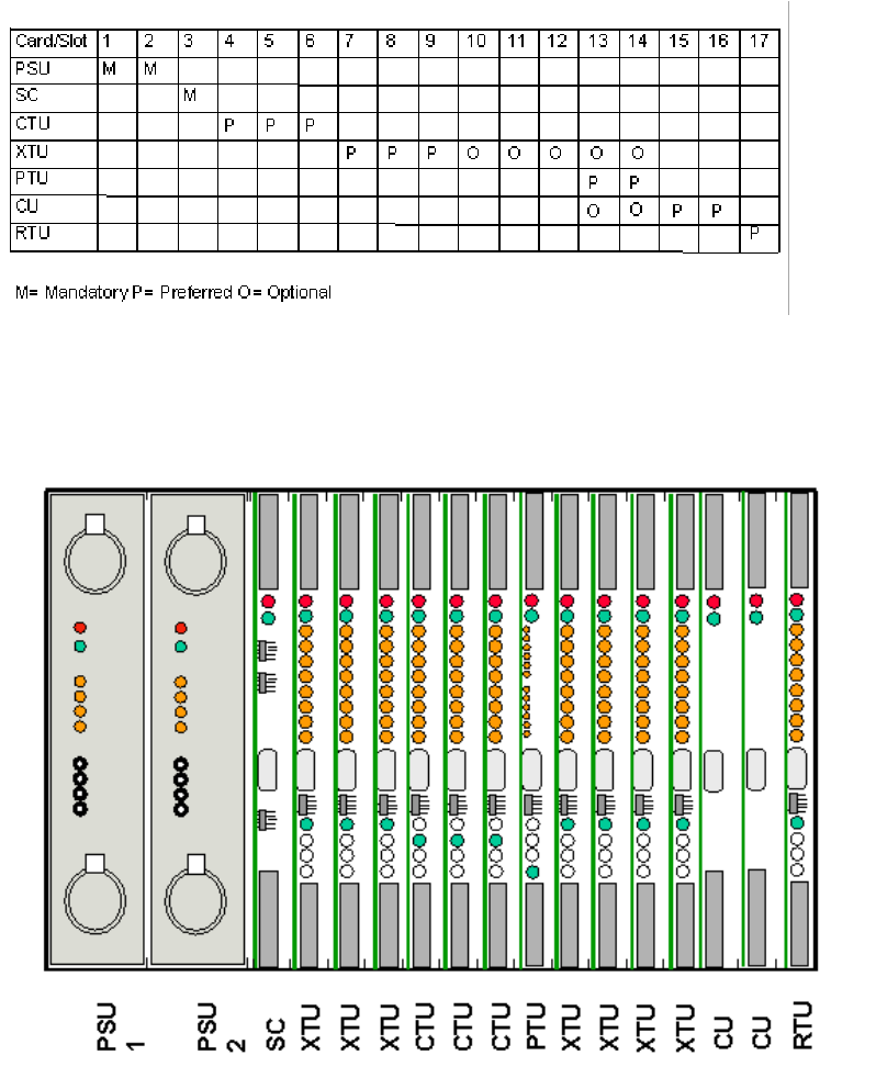
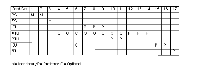
Card Insertion E1 Systems
Insert the cards into the shelves, recording the serial numbers and revision status in the test
results form. The actual cards provided will depend upon the customer configuration.
Printed Documentation
42
The maximum 64k build configuration (V5.1/CAS/ISDN) is shown above. The XTU functions
are configured using Sitespan. V5.1 does not support Data XTUs.
The maximum 32k build configuration for V5.2 is shown above. The XTU functions are
configured using Sitespan.
a. The load sharing PSUs go in slots 1&2.
b. The Shelf Controller goes in slot 3.
c. All other slot positions are configurable via Sitespan.
Installation
43
d. 3 CTUs are supported. Each CTU supports four CT modem shelves. Each CTU
may be cabled for four 120 E1s or four 75 E1s. and are placed in slots 4, 5,
and 6
e. XTUs (CAS, Data, ISDN, V5.1, V5.2 and PTU) are supported. Each XTU may be
cabled for eight 120 E1s. These can be placed in slots 5-14.(It is preferable to
build from slot 7 leaving 5 and 6 available for additional CTUs if required)
f. CU cards may go in any unused slot. (slots 15& 16 are preferred as they have no
E1 connections.
g. RTU card can go in slot 9 or 17 for card redundancy using a spare TU8 card (not
PTU), the redundant card is selected via Sitespan.
Note If installing a PTU the D-type on the backplane must be fitted with a D-Type to RJ45
adapter. The RJ45 to DB25 connector currently must be connected onto the lower of the two
25-way AC connectors (even though the activity lights work if connected to the top).
The preferred E1 options are shown below
Card Insertion T1 Systems
Insert the cards into the shelves, recording the serial numbers and revision status in the test
results form. The actual cards provided will depend upon the customer configuration.
a) The load sharing PSUs go in slots 1&2.
b) The Shelf Controller goes in slot 3.
Printed Documentation
44
c) All other slot positions are configurable via Sitespan.
d) 3 CTUs are supported. Each CTU supports four CT modem shelves. Each CTU may
be cabled for eight 120 T1s. and are placed in slots 7, 8, and 9
e) XTUs (GR303, CAS, Data, ISDN, V5.1, V5.2 and PTU) are supported. Each XTU
may be cabled for eight 120 E1s. These can be placed in slots 8-14.(It is preferable
to build from slot 10 leaving 8 and 9 available for additional CTUs if required) and in
slots 4,5 and 6.
f) CU cards may go in any unused slot. (slots 15& 16 are preferred as they have no T1
connections.
g) RTU card can go in slot 9 or 17 for card redundancy using a spare TU8 card (not
PTU), the redundant card is selected via Sitespan.
Note If installing a PTU the D-type on the backplane must be fitted with a D-Type to
RJ45 adapter. The RJ45 to DB25 connector currently must be connected onto the
lower of the two 25-way AC connectors (even though the activity lights work if
connected to the top).
The preferred card positions are shown in the table below.
Installation
45
AS4000 CT Shelf Cabling and Wiring
Central Terminal Rack E1 Cabling 75 ohm
From the site survey, confirm the location of the Digital Distribution Frame (DDF) if a DDF is
to be used or the Backhaul/Access Concentrator if the E1 feeds are fed directs to the
equipment. The length of E1 feeds should not exceed 250 metres
Note: This must be a SELV port of an EN 60950 approved product.
E1 Rack Cable Runs
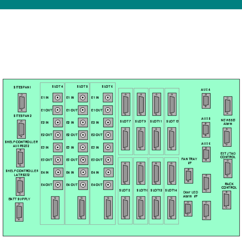
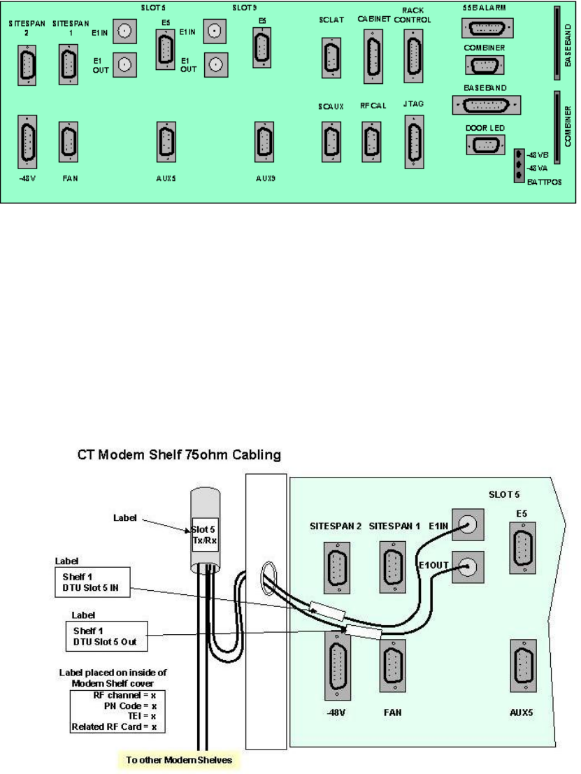
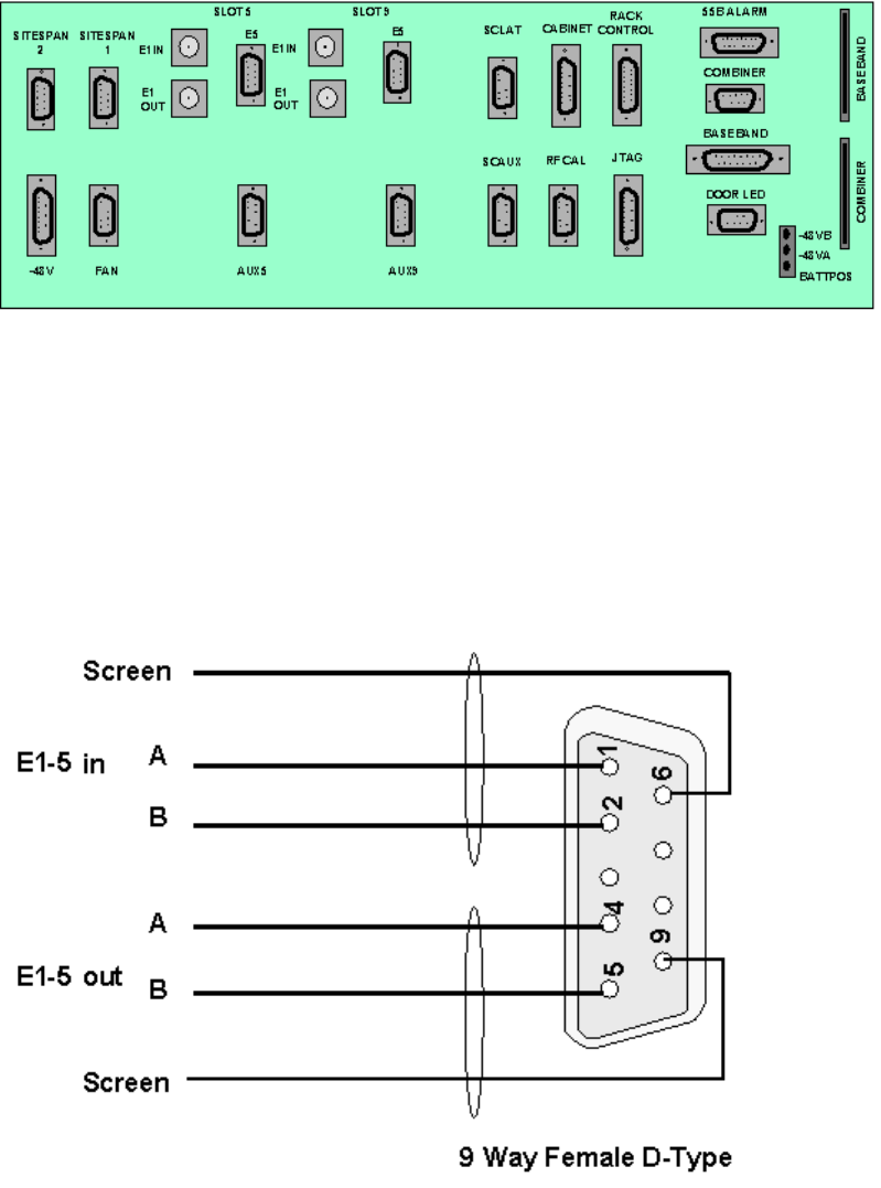
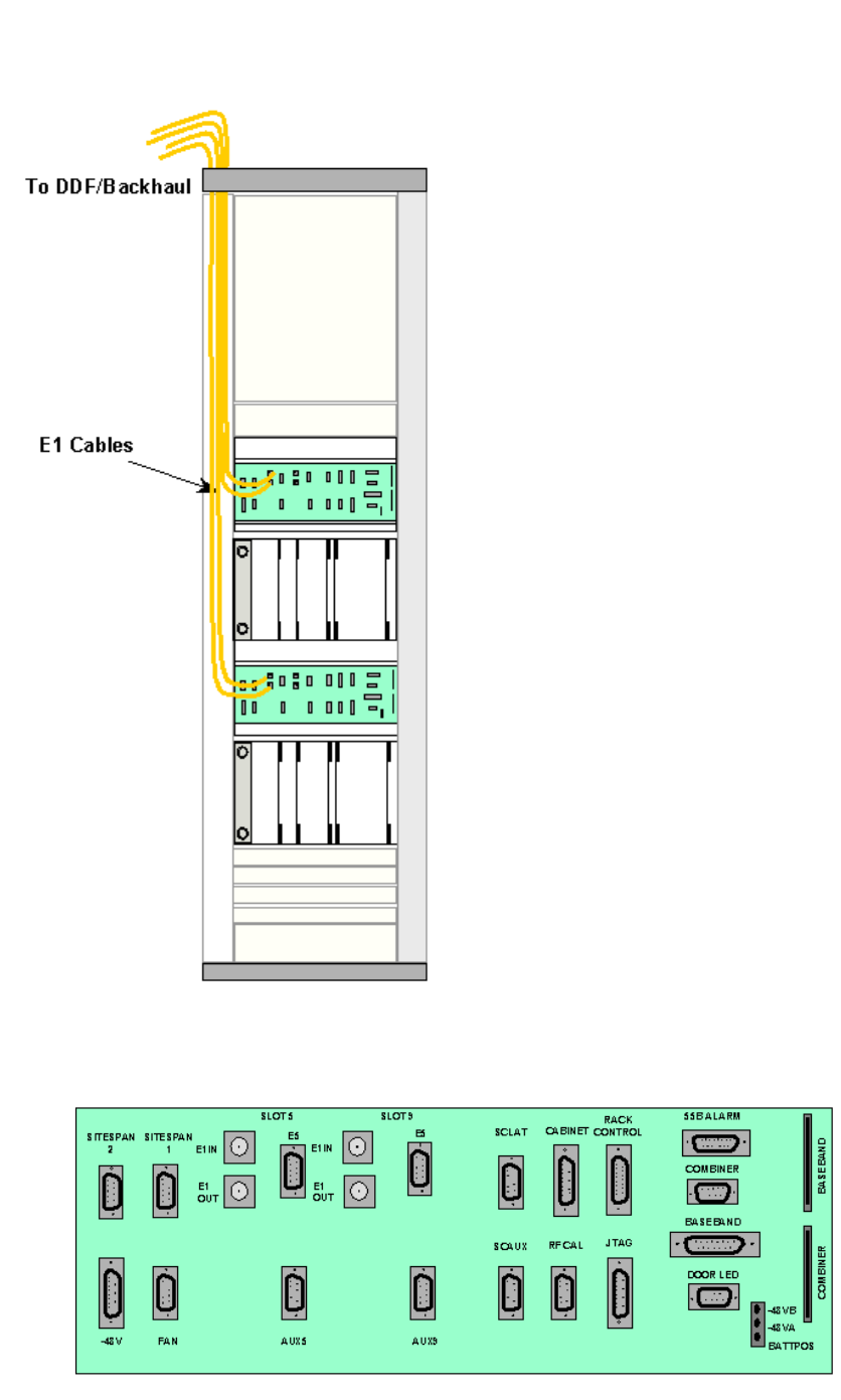
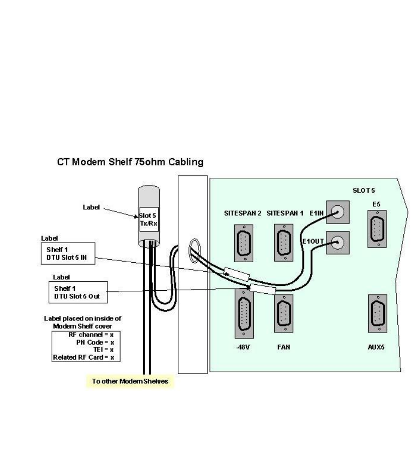
CT Modem Shelf interface connections to shelf backplane 303-1001-900
Printed Documentation
46
75 Ohm Shelf Interface Connections
Run the E1 co-axial cables from the modem shelf to the allocated positions on the
DDF/Backhaul. (Two cables per shelf in normal working, four cables per shelf in protected
mode). In partial equipped installations it may be appropriate to run enough cables to cater for
a complete rack of equipment. This reduces the need to disturb original installation when
adding additional equipment.
Feed the E1 cables through the top left hand side of the rack, and down the front of the rack.
Identify and label each cable at both ends as well as the DDF/Backhaul positions.
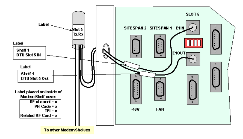
Terminate all cables with BNC co-axial connectors.
Connect the E1 ports on the DDF to E1IN Slot 5 and E1OUT Slot 5 BNC connectors on shelf
interface connections located on the modem shelf interface panel.
Ensure that the respective E1 ports have been configured on the DDF/Backhaul
Tie in cables as necessary using suitable cable ties, trim, leaving no sharp edges.
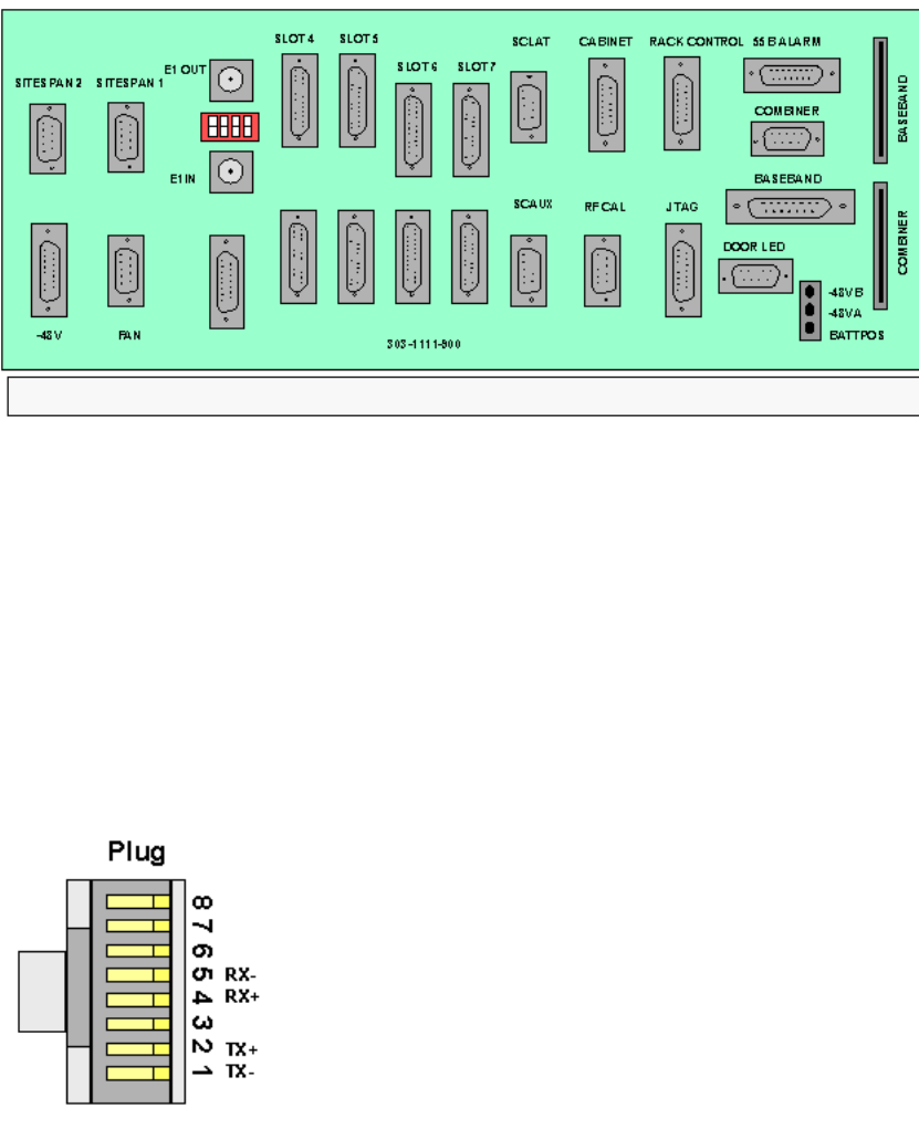
CT Modem Shelf interface connections to shelf interface panel 303-1111-
900
Installation
47
Shelf Interface Panel 303-1111-900
75 Ohm Shelf Interface Connections
Run the E1 co-axial cables from the modem shelf to the allocated positions on the
DDF/Backhaul. (Two cables per shelf in normal working, four cables per shelf in protected
mode). In partial equipped installations it may be appropriate to run enough cables to cater for
a complete rack of equipment. This reduces the need to disturb original installation when
adding additional equipment.
Feed the E1 cables through the top left hand side of the rack, and down the front of the rack.
Identify and label each cable at both ends as well as the DDF/Backhaul positions.
Terminate all cables with BNC co-axial connectors.
Connect the E1 ports on the DDF to E1IN Slot 5 and E1OUT Slot 5 BNC connectors on shelf
interface connections located on the modem shelf interface panel.
Ensure that the respective E1 ports have been configured on the DDF/Backhaul
Tie in cables as necessary using suitable cable ties, trim, leaving no sharp edges.
For 75ohm working the switches below the E1 out BNC connector should be set as shown
below
Cable connections to Shelf Interface
Printed Documentation
48
Installation
49
CT Rack E1 Cabling 120 ohm
From the site survey, confirm the location of the Digital Distribution Frame (DDF) if a DDF is
to be used or the Backhaul/Access Concentrator if the E1 feeds are fed directs to the
equipment. The length of E1 feeds should not exceed 250 metres
Note: This must be a SELV port of an EN 60950 approved product.
CT Modem Shelf interface connections to shelf backplane 303-1001-900
Printed Documentation
50
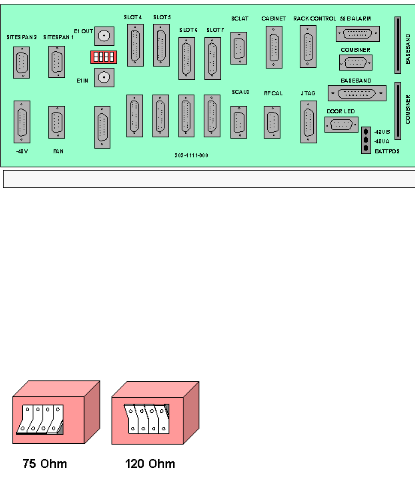
120 Ohm Shelf Interface Connections
Run the E1 120 ohm cables from the modem shelf to the allocated positions on the
DDF/Backhaul. In partial equipped installations it may be appropriate to run sufficient cables
to cater for a complete rack of equipment. This reduces the need to disturb original installation
when adding additional equipment.
Feed the E1 cables through the top left-hand side of the rack, and down the front of the rack.
Identify and label each cable at both ends as well as the DDF/Backhaul positions.
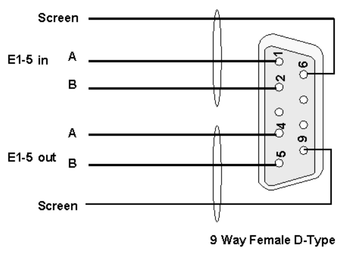
Terminate all cables at the modem shelf end with 9 pin D-Type connectors. Terminate as
detailed in below.
Connect the E1 ports on the DDF to E1 slot 5 connectors on shelf interface connections
located on the modem shelf interface panel.
Ensure that the respective E1 ports have been configured on the DDF/Backhaul
Tie in cables as necessary using suitable cable ties, trim, leaving no sharp edges.
CT Modem Shelf interface connections to shelf interface panel 303-1111-
900
Installation
51
Run the E1 cables from the modem shelf to the allocated positions on the DDF/Backhaul. In
partial equipped installations it may be appropriate to run sufficient cables to cater for a
complete rack of equipment. This reduces the need to disturb original installation when
adding additional equipment.
Feed the E1 cables through the top left-hand side of the rack, and down the front of the rack.
Identify and label each cable at both ends as well as the DDF/Backhaul positions.
Impedance Switch settings
Set the switches below the E1 out BNC connector to 120 ohm as shown below
E1 Shelf Interface Connections To RJ45
Terminate all cables with RJ45 Connectors. Terminate as detailed below.
The illustration below shows the adapter (Slot 5) and backhaul connections
Printed Documentation
52
Tie in cables as necessary using suitable cable ties, trim, leaving no sharp edges.
E1 Shelf Interface Connections To D-Type Plug
Terminate all cables at the modem shelf end with 25 pin D-Type connectors. Terminate as
detailed below.
Installation
53
CT Rack T1 Cabling
From the site survey, confirm the location of the Digital Distribution Frame (DDF) if a DDF is
to be used or the Backhaul/Access Concentrator if the T1 feeds are fed directs to the
equipment. The length of T1 feeds should not exceed 100 metres. Cat 5 FTP screened (foil &
braid) twisted pair cable should be used.
CT Modem Shelf interface connections to shelf backplane 303-1001-900
Printed Documentation
54
T1 (RJ45) interface connections to 303-1111-900 shelf interface panel
Run the T1 cables from the modem shelf to the allocated positions on the DDF/Backhaul. In
partial equipped installations it may be appropriate to run enough cables to cater for a
complete rack of equipment. This reduces the need to disturb original installation when
adding additional equipment.
Feed the T1 cables through the top left-hand side of the rack, and down the front of the rack.
Identify and label each cable at both ends as well as the DDF/Backhaul positions.
Terminate all cables with RJ45 Connectors. Terminate as detailed below.
Connect the T1 ports on the DDF to the T1 RJ45 adapter fitted to the slot 5 connector on the
shelf interface panel. Ensure that the respective T1 ports have been configured on the
DDF/Backhaul. The Primary T1 should connect to port 5 and the Secondary T1 to port 6. The
first Modem Shelf in the rack distributes the secondary T1 quarters to the other modem
shelves in the CT and expansion Rack if used.
The illustration below shows the connections to Slot 5 Modem Shelf 1using two adapters 303-
1113-900.
Installation
55
The illustration below shows connections to Modem Shelves 2,3 and 4 using adapter 303-
1113-900
Tie in cables as necessary using suitable cable ties, trim, leaving no sharp edges.
Ensure that the switches below the BNC on the Shelf Interface Panel are set for 100ohm
working
Printed Documentation
56
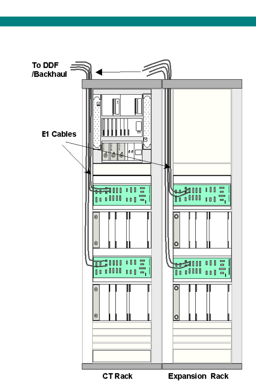
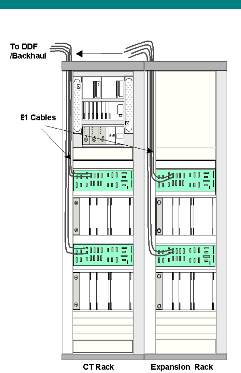
Baseband connections between CT and Expansion Racks
Inter-rack Baseband connections to Expansion Rack
Remove the blank panel located immediately below the combiner shelf on the CT Rack
Run a Baseband ribbon cable from each modem shelf in the Expansion Rack to the combiner
shelf via the hole created by the removal of the breakout sections during the rack installation.
Insert the connector into the Baseband socket on the Modem Interface shelf (see) and into
the appropriate socket on the Combiner Shelf backplane (the sockets are located behind the
switches). If using a Hybrid Rack these connections will differ from the illustration below. (see
Hybrid Rack Modification for Directional Antenna)
Combiner Shelf Ribbon Connections
Run the alarm bus ribbon from the Alarm and Breaker panel to the Alarm Bus socket in the
CT Rack wiring loom.
Installation
57
Expansion Rack Cabling
Central Terminal Expansion Rack Cabling
2Mbit/s Cabling
From the site survey, confirm the location of the Digital Distribution Frame (DDF) if a
DDF is to be used or the Backhaul/Access Concentrator if the 2Mbit/s feeds are fed
direct to the equipment. The length of 2Mbit/s feeds should not exceed 250 metres
Note: This must be a SELV port of an EN 60950 approved product.
Printed Documentation
58
1. Shelf Interface Connections.
75 Ohm Connections
Run the 2Mbit/s co-axial cables from the modem shelf to the allocated positions on the
DDF/Backhaul. (Two cables per shelf in normal working, four cables per shelf in protected
mode). In partial equipped installations it may be appropriate to run enough cables to
cater for a complete rack of equipment. This reduces the need to disturb original
installation when adding additional equipment.
Feed the 2Mbit/s cables through the top left-hand side of the rack, and down the front of
the rack.
Identify and label each cable at both ends as well as the DDF/Backhaul positions.
Terminate all cables with BNC co-axial connectors.
Connect the 2Mbit/s ports on the DDF to E1IN Slot 5 and E1OUT Slot 5 BNC connectors
on shelf interface connections located on the modem shelf interface panel.
Ensure that the respective 2Mbit/s ports have been configured on the DDF/Backhaul
Tie in cables as necessary using suitable cable ties, trim, leaving no sharp edges.
120 Ohm Connections
Run the 2Mbit/s 120 ohm cables from the modem shelf to the allocated positions on
the DDF/Backhaul. In partial equipped installations it may be appropriate to run
enough cables to cater for a complete rack of equipment. This reduces the need to
disturb original installation when adding additional equipment.
Feed the 2Mbit/s cables through the top left-hand side of the rack, and down the front
of the rack.
Identify and label each cable at both ends as well as the DDF/Backhaul positions.
Terminate all cables with 9 pin D-Type connectors. Terminate as detailed below.
Installation
59
120 ohm connection to CT modem shelf.
Connect the 2Mbit/s ports on the DDF to E5 slot 5 connectors on shelf interface
connections located on the modem shelf interface panel. If using protected mode connect
the other 2Mbit/s cables to E5 slot 9 connectors on the same panel.
Ensure that the respective 2Mbit/s ports have been configured on the DDF/Backhaul
Tie in cables as necessary using suitable cable ties, trim, leaving no sharp edges.
Printed Documentation
60
Antenna Configurations
AS4000
This section describes the various antenna configurations and modifications needed to the
baseband wiring if the AS4000 CT rack is configured so that the two modem shelves serve
separate directional antenna. and the subsequent connection arrangements when an
expansion rack is fitted.
1. Standard configuration for Antenna (omni or sectored) using 2 RFs on one Antenna
initially and 2 RFs per antenna when an Expansion Rack and second Antenna are
added
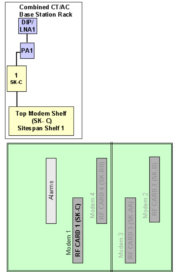
Figure 1 Combiner Shelf Ribbon Connections Before Modification
2. Rack Modification for two separate directional Antenna using 1RF per Antenna
initially and 2 RFs per sector when an Expansion Rack is added
The modification consists of re arranging the baseband cables from the modem shelves such
that the bottom shelf in the CT rack now connects to RF Card 3 and consequently will feed
into the antenna connected to DIP/LNA 2. If an expansion Rack is fitted then the top shelf
connects to RF Card 2 and will feed into the antenna connected to DIP/LNA 2. A block
diagram of the system after modification is shown below.
Modification to CT Rack
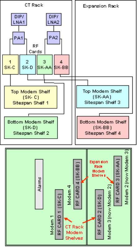
Installation
61
1. Remove the blank panel located immediately below the Combiner Shelf on the DA
Rack.
1. Swap the baseband connectors from Modem Shelves 2 and 3 on the
Combiner Shelf backplane (the sockets are located behind the switches on
the Combiner Shelf).
AS4020
This section describes the various antenna configurations and connections needed to the
baseband wiring
1. Standard configuration for antenna (omni or sectored)
Printed Documentation
62
Combiner Shelf Ribbon Connections Standard Config
Mixed AS4000 / AS4020
Configuration for AS4020 where AS4000 exists on sectored /dual omni antenna
Installation
63
Configuration for AS4020 where AS4000 exists on single omni and additional antenna
added
Integrated Base Station Rack
The antenna is configured as shown in the diagrams below.
Printed Documentation
64
Installation
65
Interface Connections
This page contains miscellaneous interface and connector details.
Printed Documentation
66
120 Ohm Interface Connections on DA Access Concentrator Backplane
Interface Adaptor EIA 530 to V35
Interface Adapter EIA 530 to X21
EIA 530 loopback Connector
Installation
67
Printed Documentation
68
CT Rack Labelling
Central Terminal Rack

Installation
69
BNC Terminations to Coax

Printed Documentation
70
Type 43 Terminations to Coax

Installation
71
Printed Documentation
72
Central Terminal Card Installation
The CT rack is shipped with shelves fitted to customer requirements and internal cabling
complete.
Preliminary
In a new installation ensure that the CT Circuit Breakers located on the lower assembly of the
Combiner Shelf are set to the OFF position (Down). See and that the breakers on the Fuse
and Alarm panel of the Expansion Rack are switched are set to the OFF position (down) See.
Warning: Before handling any cards or modules, observe full anti-static
precautions
CAUTION PA INSERTION
Care should be taken when installing PAs to ensure that the card connector mates with the
backplane connector correctly. Any attempt to ram the card home or force the card into he
slot may cause damage to the connector. Insert the card until the connectors engage, ease
the card into the backplane until fully engaged. Lock top and bottom with a screwdriver. If
resistance is met, remove the card and reinsert. If difficulty persists contact the Airspan
service centre.
CAUTION DIP/LNA INSERTION
Care should be taken when installing DIP/LNAs to ensure that the card connector mates with
the backplane connector correctly. Any attempt to ram the card home or force the card into he
slot may cause damage to the connector. The board extractor levers may be used to assist
with insertion, when the card is home press the body of the DIP/LNA to ensure that the
connector is fully engaged. If resistance is met remove the card and reinsert. If difficulty
persists contact the Airspan service centre.
WARNING: Isolation of power from the rack is only achieved by ensuring that both
circuit breakers are in the off position.
Part of RF Combiner Shelf showing Circuit Breakers.
Installation
73
Expansion Rack Fuse and Alarm Panel
Ensure that the end of suite fuses are adequately rated and insert these into the respective
fuse holder positions.
Card Insertion
Insert the cards into the shelves, recording the serial numbers and revision status in the test
form.
Printed Documentation
74
Card Insertion DA Rack
Card Insertion Expansion Rack
Installation
75
Card Provision for New Installation
With the initial installation it is advisable to install the cards in both the combiner shelf and the
modem shelves with the power switched off.
Fit Cards in RF Combiner Shelf
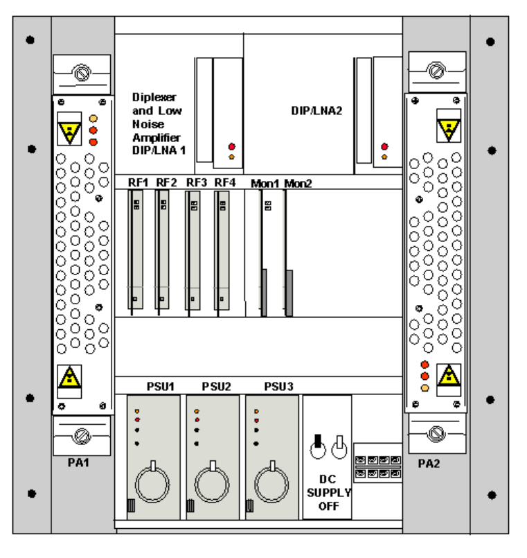
Printed Documentation
76
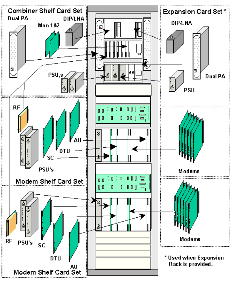
Insert the following modules and secure:-
1 RF Power Amplifier Module (2 PA’s) in the left hand position in the combiner shelf
1 x Low Noise Amplifier + Diplexer (DIP/LNA 1) (Terminate output with 50ohm
termination.)
2 x PSU’s
2 x Combiner Monitor Card (Monitor 1 303-043-900 & Monitor 2 303-043-901)
For each modem shelf provided install 1 x RF Card (RF)
If an Expansion Rack has been installed also insert the following modules in the RF combiner
shelf located in the DA CT Rack and secure:-
1 RF Power Amplifier Module (2 PAs per module) in the right hand position in the
combiner shelf - note the orientation of this module.
1 DIP/LNA (Terminate output with 50ohm termination.)
1 x PSU
For each modem shelf provided install 1 x RF Card (RF)
Fit Cards in Modem Shelf
Installation
77
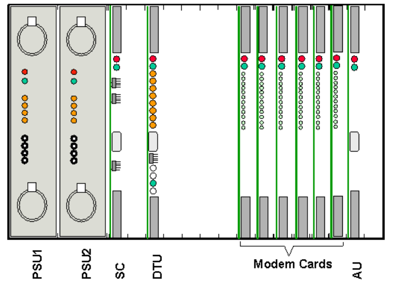
Insert the following cards into each Modem Shelf: -
2 x PSUs Slots 1 and 2.
1 x Analogue Card (AU) Slot 16.
1 x Demand Assignment Tributary Card (DTU). Slot 5.
1 x Shelf Controller (SC) Slot 3.
Modem Cards Slots 10 to 15.
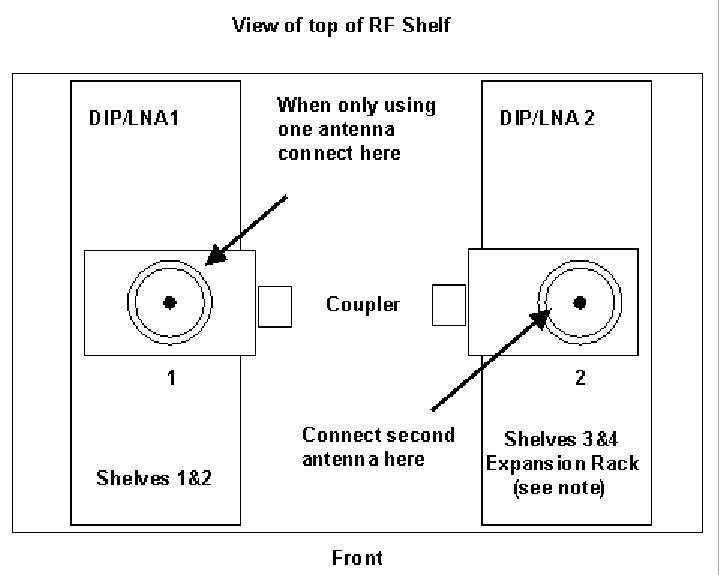
Fit RF Coupler for using a DACU
Fit RF Coupler for connection of systems to the DA Control Unit for commissioning.
A 30dB coupler should be fitted to the male N-Type connector at the top of the DIP/LNA1 and
the DIP/LNA2 (if fitted). Port J1 fits onto the DIP/LNA module and the antenna feed fits on to
port J2. The coupler should be orientated as shown in so that the SMA port faces to the right
side of the rack (when viewed from the front) to allow easy access for test leads. Note some
3.4-3.6GHz systems may not have couplers fitted.
Connect Antenna
If the Rack is fitted with couplers connect antenna at this stage. Do not connect antenna at
this stage on systems without couplers fitted.
Note: See Antenna and Feeder Installation and Commissioning Procedure, 605-0000-503 for
details of feeder grounding.
Printed Documentation
78
Some Installations may use directional antennas and use two DIP/LNAs for a two shelf
system. in this situation Shelf 1 connects to DIP/LNA 1 and Shelf 2 to DIP/LNA 2. See Hybrid
Rack Modification for Directional Antenna
Two Antenna Installations
In new installations the protective boots of the antenna feeder tails free ends should be kept
in position until the tail is actually connected. Form one of the tails carefully (avoid tight bends,
minimum bend radius is 125mm), to connect with the N-Type sockets on the Coupler on top
of the DIP/LNA module in the Combiner Shelf. If PA2 and the DIP/LNA2 units are fitted the
second antenna should be connected to the DIP/LNA2.
Single Antenna Installations
If modem shelves 3 and 4 are not installed it is possible to install only 1 antenna and connect
the feeder to the output port of DIP/LNA1 Unit.
If the Combiner Shelf is not equipped with DIP/LNA2, it is recommended that the second
antenna should be terminated with a 50ohm termination. The termination can be made either
at the base of the dipole if only one feeder is fitted, or at the base of the second feeder if the
second feeder has been provided in readiness for future shelf expansion.
Card Provision into existing installation
a) Shelf 3 (Top shelf of expansion Rack)
When installing cards into an existing installation the power is already connected to the DA
CT Rack and the cards should be inserted in the order listed below.
Insert the following cards into the Combiner Shelf (located in the DA CT Rack):-
1 RF Power Amplifier module (2 PAs per module) in the right hand position in the
combiner shelf located in the combiner rack.- Note orientation of the PA module.
1 DIP/LNA2 (Terminate output with 50ohm termination.)
1 x PSU’s
1 x RF Card (RF) (Third Slot)
Insert the following cards into the Modem Shelf:-

Installation
79
2 x PSUs. Slots 1 and 2.
1 x Shelf Controller Card
1 x Analogue Card (AU). Slot 16.
1 x Demand Assignment Tributary Card (DTU). Slot 5.
Modem Cards Slots 10 to15.
b) Shelf 2 (CT Rack) or Shelf 4 (Expansion Rack)
When installing cards into an existing installation the power is already connected and the
cards should be inserted in the order listed below.
Insert the following cards into the Combining Shelf:-
1 x RF Card (RF)(in slot 2 for modem shelf 2 or slot 4 for modem shelf 4)
Insert the following cards into the Modem Shelf:-
2 x PSUs Slots 1 and 2.
1 x Shelf Controller Card
1 x Analogue Card (AU) Slot 16.
1 x Demand Assignment Tributary Card (DTU).Slot 5.
Modem cards Slots 10 to15.
Printed Documentation
80
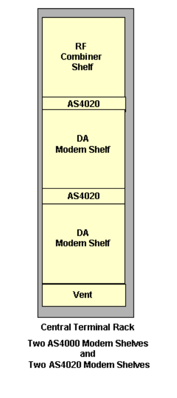
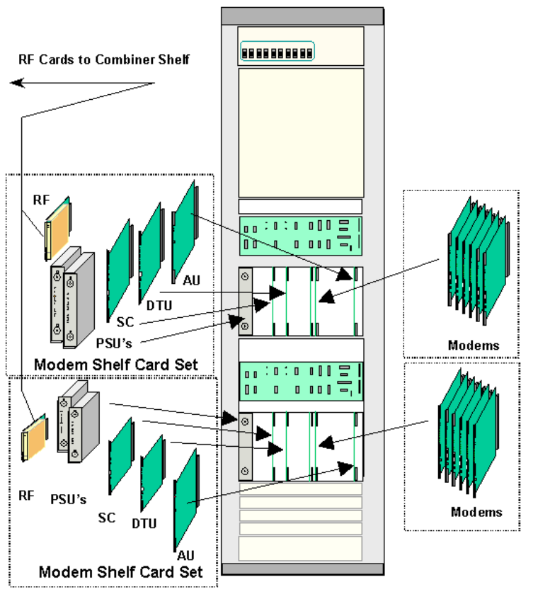
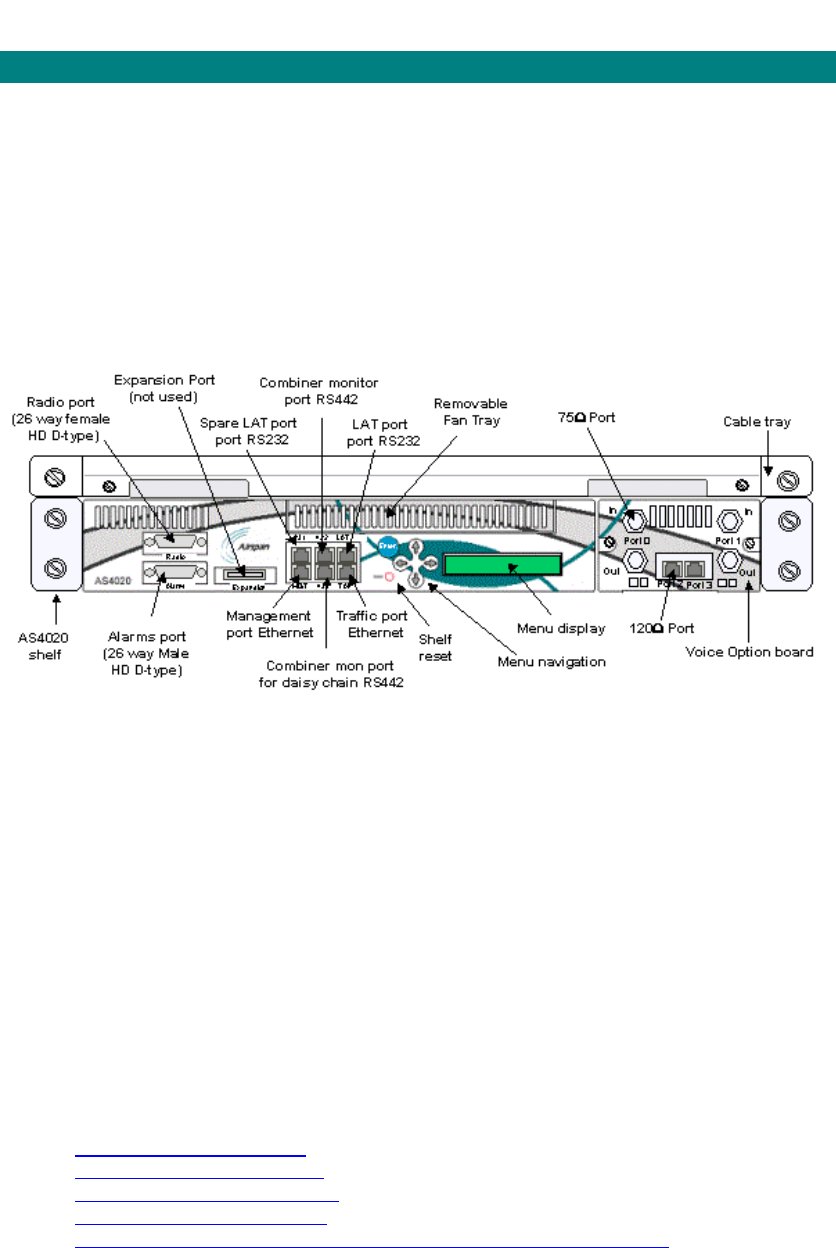
AS4020 CT Shelf Installation and Cabling
Shelf Connections
AS4020 comprises of a single 65mm (approximately 1.5u) high shelf, which can be fitted in an
ETSI rack, 19" rack or 21" rack. AS4020 is flexible in its deployment, although is must remain
within a couple of meters of the radio sub-system. Initially the AS4020 CT shelf is fitted within
the AS4000 CT rack with the Radio sub-system, and optionally alongside up to two AS4000
CT shelves. Alternatively a half-height AS4000 CT rack can fit four AS4020 shelves and a
radio sub-system.
All connections to the AS4020 shelf are through the front of the unit, except DC power, which
is fed from the RF combiner shelf to the rear of the unit. the illustration below shows a the
interfaces available on the front of the AS4020 CT shelf. All connections are made to the front
panel with the exception of the power connection at the left hand side of the shelf.
All cables should enter via the cable tray above the shelf. Cable entry to the main panel is via
the left hand opening and via the right hand opening to the option panel as this avoids the
possibility of cables obscuring the menu.
The AS4020 CT shelf is cooled using fans that are hot-pluggable in the event of failure. An
AS4020 CT shelf can only be installed in a weather-protected location.
The AS4020 CT shelf provides a terminal connection for initial configuration of the Ethernet
ports, a method for commissioning the system, and menus for basic systems diagnostics. In
addition to the terminal interface, AS4020 contains an LCD screen to provide alarm details
and limited status information.
Full configuration of AS4020 is via the management system, which can be a local Ethernet
connection, or via the network Ethernet interface.
The AS4020 CT shelf provides the switching functionality of the system, as well as managing
radio access on both the uplink and downlink. The shelf is also responsible for the radio
interface architecture, namely BDM, dynamic modulation, and RTS/CTS signalling.
When adding shelves to an existing AS4000 system use the following diagrams to determine
the points to connect the radio port and combiner monitor connections.
o Adding one AS4020 shelf
o Adding two AS4020 shelves
o Adding three AS4020 shelves
o Adding four AS4020 shelves
o Adding Two AS4020 Shelves to an existing Two AS4000 shelf rack
Installing the Voice Option Board
Units are shipped with the option board installed if specified, but options boards may be
added to existing shelves.
Installation
81
1. Remove the blanking plate by removing the two screws that secure it to the chassis
2. Carefully slide the option board into the shelf ensuring that the connector mates with
the backplane.
3. Secure with screws to the chassis.
Printed Documentation
82
AS4020 Shelf Installation upgrade into AS4000 Rack
This topic covers the installation of AS4020 shelves as an upgrade into an existing AS4000
rack.
The AS4020 fits immediately below the combiner shelf in the central terminal rack. If more
than one AS4020 is to be installed existing modem shelves will need to be removed. The
AS4020 installation wiring diagrams in this manual should be used in conjunction with this
topic.
Parts required.
1
shelf
2
shelves
(1 x
AS4000
exists)
2 shelves
(2 x
AS4000
exists)
3
shelves 4
shelves
AS4020 shelf. 1 2 2 3 4
Cable tray and cover + 2 x cage
nuts, screws and washers. 1 2 2 3 4
Baseband connecting lead (part
no 454-0010-135). 1 2 2 3 4
Power connecting lead (part no
454-0010-136). 1 2 2 3 4
Alarm connecting lead (454-0010-
134). 1 2 2 3 4
Alarm Breakout connector (454-
0010-137). 1 1 2 2 2
Ethernet connecting lead (as
required).
Installing an AS4020 shelf into an existing CT rack.
1. If possible power down the rack. Note: It is possible to connect the AS4020 shelf
without removing the rack from service. However if the AS4020 is connecting via
an existing PA the service using the other RF channel in the PA must be taken
out of service to set TX sensitivity.
2. Remove the cover from the combiner switch panel and plate below the right
hand PA.
3. Remove the side panels from the rack.
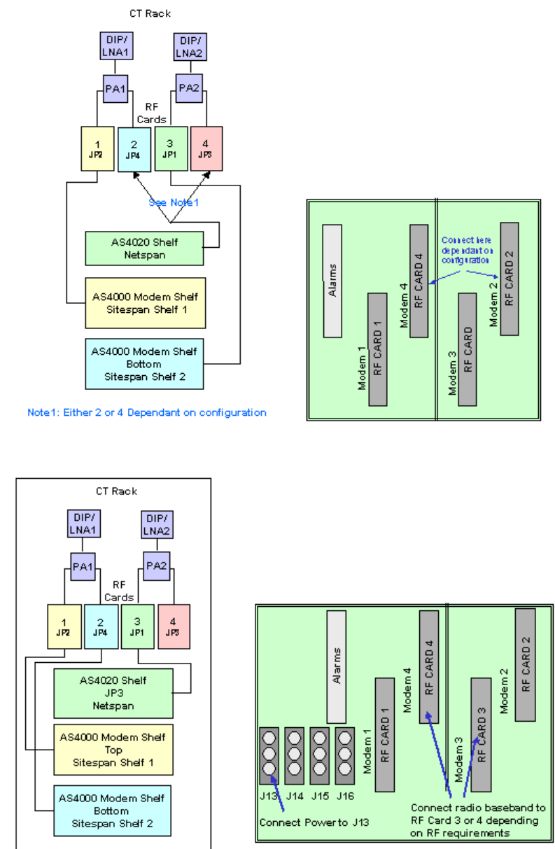
4. Remove existing 100mm cover from below the combiner shelf.
5. Run the power connecting lead (part no 454-0010-136) from the combiner shelf
backplane (socket J13) to the left hand side of the shelf position for the AS4020.
In a 4 Shelf loom this socket may have a plug inserted but it should not be
connected to any equipment and can be removed.
In order to connect the lead it is best to remove the switch from the combiner
shelf. If the rack is still in service the power plug can be removed and the new one
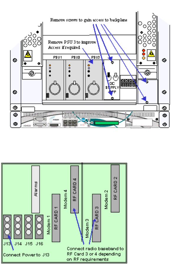
Installation
83
inserted in J13 by removing the PSU from the third position and carefully inserting
the hand into the gap. If there is difficulty removing the plig it is possible to loosen
the switch assembly with the power still on but extreme care must be taken to
avoid short circuiting the DC supply wiring.
6. If the rack is powered down remove the two screws retaining the supply switch
panel on the combiner self to gain access to the combiner shelf back plane.
Remove the plate on the right hand side of the combiner. To improve access the
third PSU may also be removed.
7. Thread up connecting lead (part no 454-0010-135) from the shelf position to the
backplane of the combiner shelf . Connect to the IDC connector corresponding to
the RF card to be used.
8. Remove the Alarm Connector from JP4(Alarm) on the AS4000 shelf 1 backplane
and insert the connector 454-0010-137 between JP4 and the connector
9. Connect the combiner monitor connecting lead (454-0010-134) into the port
labeled '442' (there are two ports labelled '442' the top one should be used. ( the
other port labelled '442 ' is used when daisy chaining the monitor to other AS4020
shelves).
10. The AS4020 is installed at the bottom of the 100mm gap created by the removal
of the blanking panel. Before inserting the shelf connect the power lead to the 15
way D-type socket at the rear of the shelf. and ease into position. It is not possible
to connect the power to the shelf once the shelf is in position.
11. Secure the shelf with four cross head screws and locking washers.

Printed Documentation
84
12. Fit the cable tray immediately above the AS4020 shelf. Fix the shelf with two
cross head screws and locking washers.
13. Connect the IDC end of the combiner monitor connecting lead (454-0010-134) to
the IDC connector in the cable assembly 454-0010-137 added in step 8.
14. Connect part no 454-0010-135 to the 26way high density D-type labeled 'Radio'
on the front panel of the AS4020
15. For additional shelves connect cables as shown in the AS4020 installation
diagrams and follow the steps above where applicable.
16. Use a straight connected Ethernet cables to connect the patch panel /router/ IP
network/ etc to the Management Port and Traffic Ports.
17. Replace the covers removed from the combiner shelf.
18. Attach the front cover to the shelf tray(s)
19. Replace the side panels on the rack and secure with four retaining screws.
The unit is now ready for commissioning.
For details of interface connections see AS4020 Interface Connections
Note if installing more than one shelf the same instructions apply as above but the
connections will differ see the accompanying diagrams.
Installation
85
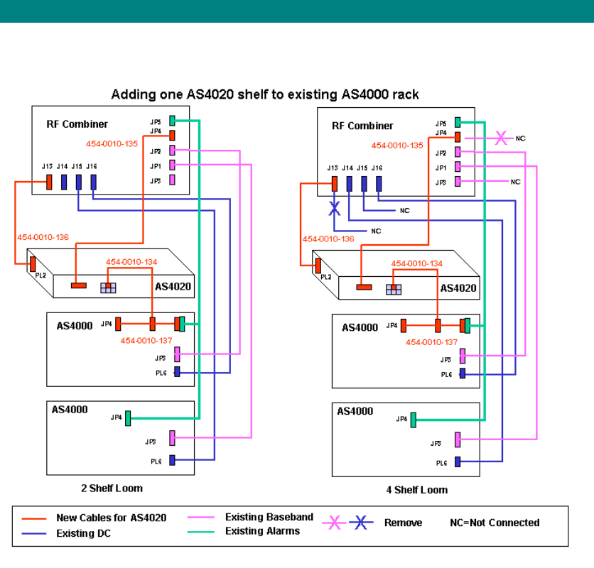
Adding one AS4020 shelf to existing rack
The following installation diagrams show the additions to wiring that need to be made when
adding 1 AS4020 shelf into existing rack.
Printed Documentation
86
Adding two AS4020 shelves to existing rack
The following installation diagrams show the additions to wiring that need to be made when
adding 2 AS4020 shelves into existing rack.
Installation
87
Adding three AS4020 shelves to existing rack
The following installation diagrams show the additions to wiring that need to be made when
adding 3 AS4020 shelves into existing rack.
Printed Documentation
88
Adding four AS4020 shelves to existing rack
The following installation diagrams show the additions to wiring that need to be made when
adding 4 AS4020 shelves into existing rack.

Installation
89
Adding two AS4020 with two AS4000
If it is required to put two AS4020 shelves into an existing two shelf AS4000 installation the
first AS4020 shelf should be placed between the combiner shelf and the top AS4000 shelf. To
provide the second AS4020 shelf it is necessary to remove the bottom vent panel and move
the lower AS4000 shelf down to accommodate the second AS4020 shelf below the top
AS4000 shelf.
The shelves should be cabled as shown below. The actual connections to the RF cards at the
combiner shelf may differ from the diagram dependant on the antenna configuration.
Printed Documentation
90
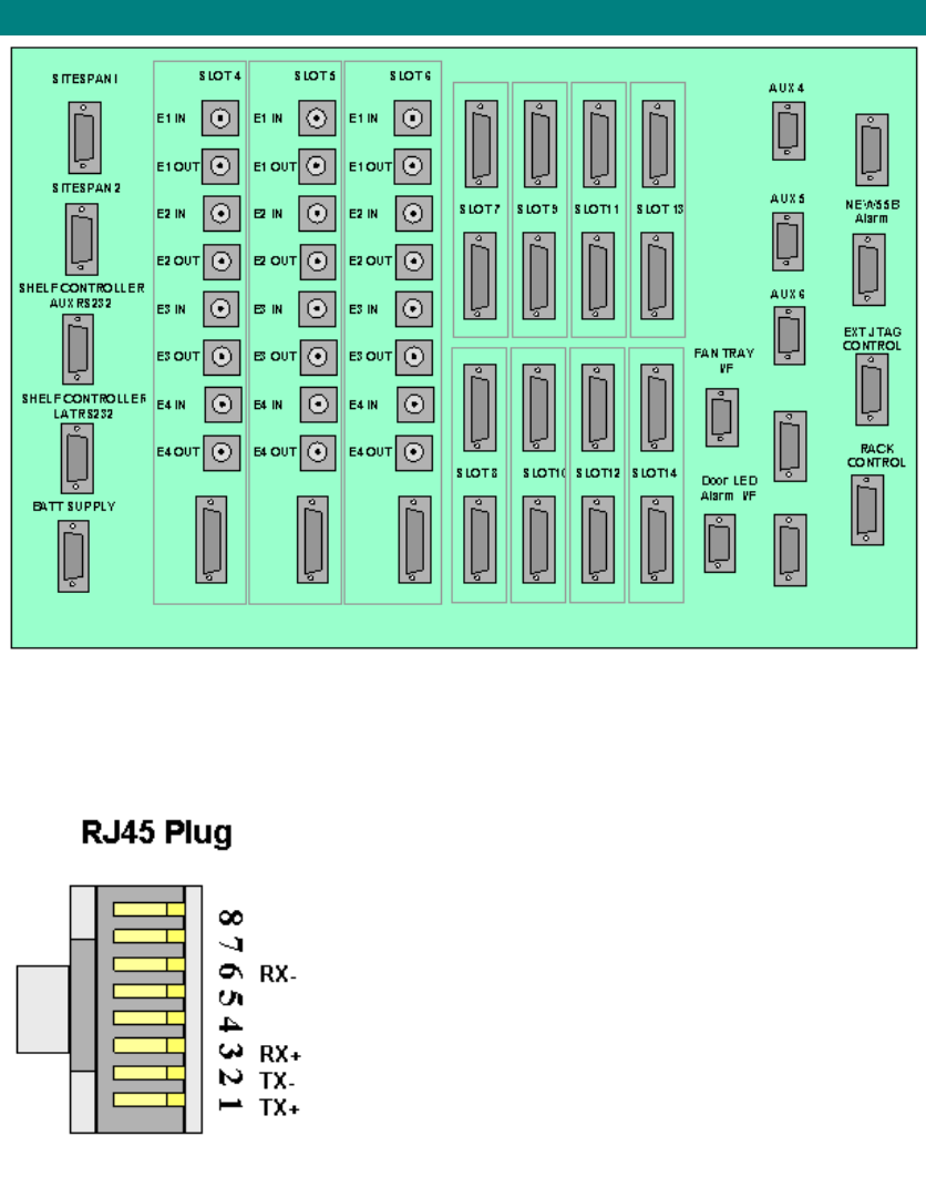
AS4020 Interface Connections
Alarm Wiring 26way High Density Male D-type.
Pin Description
1 DC 3.3V
2 Reset
3 Reset
5 &
22 Service
7 &
24 Attention
9 &
26 Fail
17 Reset
18 Earth
19 Reset
LAT Socket
Pin Description
6 Earth
7 Tx Out
8 Rx In
RS442
Pin Description
1 RX +
2 RX -
3 TX +
6 TX -
Traffic
Pin Description
1 TX+
2 TX -
3 RX+
6 RX -
Management Port
Pin Description
1 TX+
2 TX -
3 RX+
6 RX -
Option Unit
Pin Description
1 RD+ (input to option
card from AC)
2 RD-
4 TD+ (output from
option card to AC)
5 TD -

91
Setup and Test
System Testing
This section sets up the parameters for the system and the connection to Netspan
Refer to the Netspan, document no. 605-0000-509 for the detailed configuration and set
up procedures of Netspan and the AS4020 System.
General
The following procedures need to be carried out in order to verify the functionality and
operation of all cards fitted into the Central Terminal prior to placing the AS4000/4020
system into service.
It is preferable to connect the As4000/AS4020 to a ISP when commissioning. This allows
the CT to be connected and test calls made over the system during the commissioning
process.
If during testing, a fault occurs preventing the continuation of the test, the faulty module or
card should be replaced and the test repeated for the new card module and any other
tests that are affected by the performance of that card.
All results must be entered on the Commissioning Test Result Sheets (Copies are
included in this manual and should be printed as required). Test forms should be
photocopied as needed, ensure that sufficient copies of all sheets are available prior to
the commencement of commissioning tests.
There are two activities required; a) the network management centre should create the
sites and equipment in the database (frequency and PN ),using Netspan b) the field
engineer should commission the equipment to the recommended parameters (output
power and system receiver sensitivity).
Pre-Commissioning at the Network Management Centre
For a completely new installation, the NMC administrator should create the sites and
equipment racks in each site ( with the frequency, PN etc entered, in preparation of the
actual equipment installation and commissioning. When expanding the system with
additional CT sites, the administrator should add the extra CT equipment using Netspan.
During field commissioning, the field engineer will use a local laptop running copy of
STMON to control the test ST.
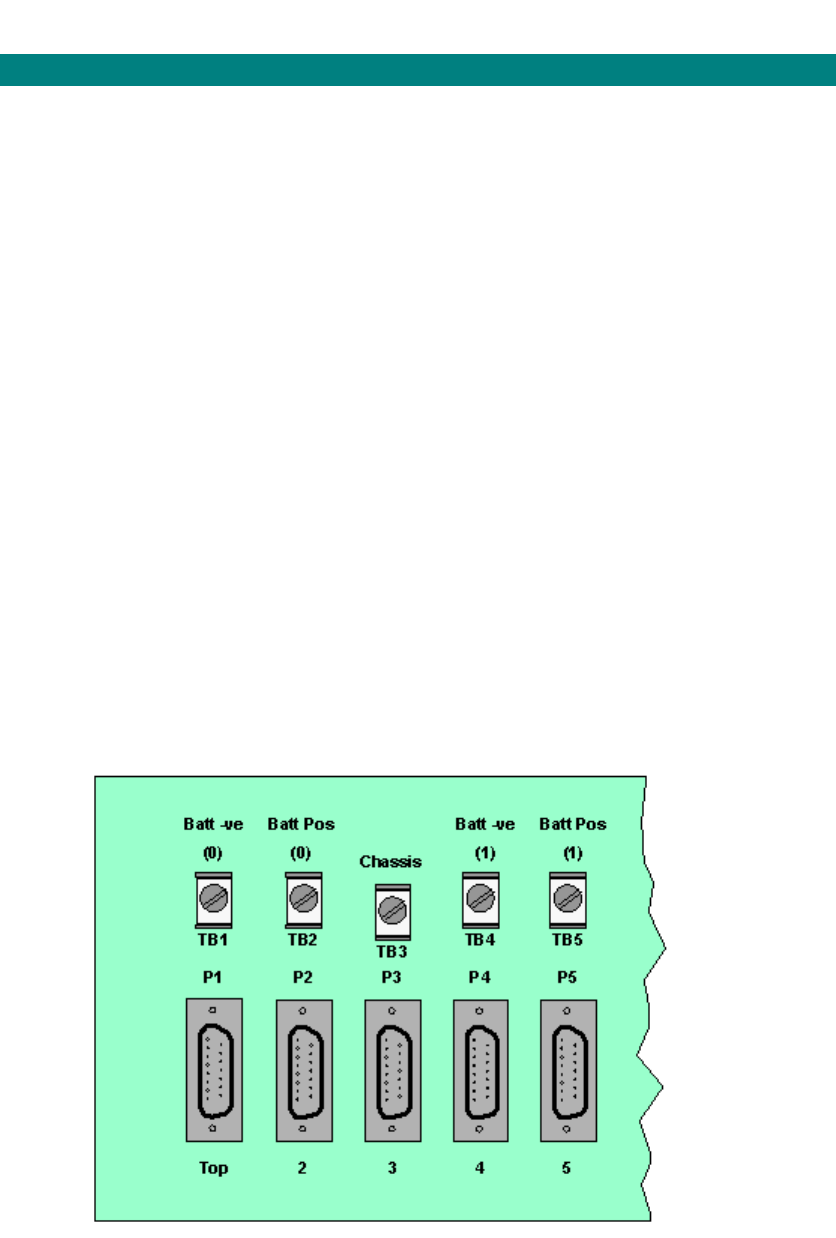
Printed Documentation
92
AS4000 AC Setup and Test
Access Concentrator: Turn-Up and DC measurements
Pre-Checks
Before commencing the turn-up of the rack check that the serial number and Rev levels of all
card have been entered into the test form and that the SC boot chip version is recorded.
DO NOT power up or plug any cards fully into their slots at this stage.
Router Port Availability. If the Sitespan Server is located at the NMC and connected via a
router confirm the IP address for the router at the AC and the port for connection (typically a
RJ45 cabled to the AC from the back of the router.
Apply a loopback on the designated router port (pins 3 to 6 on an RJ45).
Check that the router at the AC can be pinged and the loopback seen from the Sitespan
Server PC at the NMC by using a simple communication application as hyper terminal at the
COM port intended for Sitespan use.
Isolate all E1/T1 cables from the AC by removing the links at the DDF.
Disconnect all cards from the backplane by pulling forward in the card guides so that the
power will not be applied to the cards when the shelf is switched on.
Rack Turn-Up and Measuring Input Voltage (Test 1a)
This section describes the procedure for measuring and connecting DC to the rack, checking
that the cards have the correct alarm indications on power-up and measuring the PSU output
voltages.
Unscrew retaining screws on the face of the Fuse and Alarm Panel. Hinge forward the panel
and using the DMM measure and record the Exchange DC voltage supply across the input
terminals (TB1(-); TB2+;.for Supply 1 and TB4(-); TB5(+) for supply 2). Check that the polarity
is correct. Ensure that the voltage measured complies with the site nominal voltage and is
within the limits specified on the test results sheet.
Test Voltage
Record the measured voltage on the test results sheet.
3. Turn-Up AC Shelves: (Tests 1b)
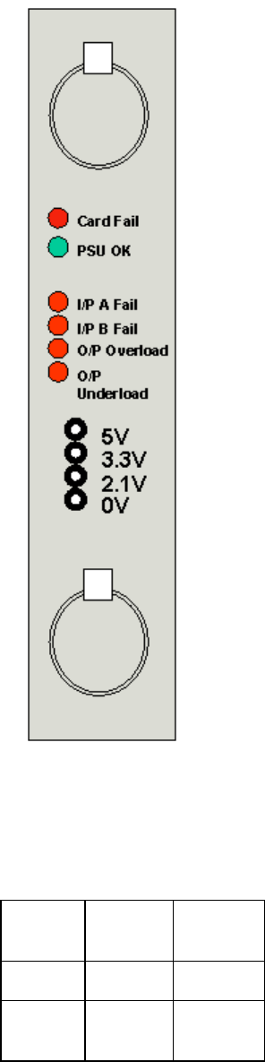
Setup and Test
93
Place one PSU in the shelf . Switch the Rack ON by placing one breaker on. The two
breakers duplicate power to each shelf and the shelves will still function if one power supply
fails though the LED indicators on the power supplies will not be on. The PSU should show a
green LED and one supply fail LED. Switch on the second breaker and the Red LED should
extinguish.
Switch off and place the second PSU in the shelf and repeat the process described in the
paragraph above.
Access Concentrator Shelf PSU
Place a SC Card into the shelf to provide a load. Switch both breakers on and measure and
record the DC voltage at the o/p of each PSU.
Ensure that the voltages measured are within the limit shown below. Record the results in test
form.
Voltage
Upper
Limit Lower
Limit
5V DC 5.25V 4.75V
3.3V
DC 3.3V 3.0V

Printed Documentation
94
2.1V
DC 2.1V 2V
Access Concentrator Shelf PSU Voltages.
Switch Rack off and plug in all the remaining cards in their respective positions on the shelf
Repeat Test 1b for the other AC shelves if fitted.
Setup and Test
95
Setting Up the Access Concentrator
The Access Concentrator is setup using Sitespan in stand alone mode and Netspan does not
need to be connected for the AC to be set up
Setting the TEI and Baud Rate for Netspan Connection
1. Connect PC using AS7030 SiteStart software to the LAT port on the front of the shelf
controller of the Shelf being commissioned..
2. Set the TEI to the value designated during system planning. The TEI number must be
unique to the Network managed by Netspan.
3. Set the Baud Rate for connection. The same rate must be set when setting up AC Shelf
Properties later in this commissioning process.
To commission the AC Shelf the Shelf must be connected via an RS232 interface to a
Sitespan server. However the settings made during the setup process must be transferred to
the NMS Netspan before it server is connected or values set within the shelf during this
process will be overwritten by Netspan when it is connected. Alternatively if Netspan is
available the setting up can be done using Netspan
Creating AC Shelf/Rack on Sitespan
1. Connect the Field Engineer Laptop to the AC shelf Sitespan port.
2. Run Sitespan Server software on the laptop.
3. Open Sitespan Client application.
4. Create the Server to make connection to (usually the name of the PC).
5. Connect to the Server.
6. Create Site.
7. Highlight the site, click right mouse button and select Create Child Element
8. Select Airspan AC Rack
9. Highlight the rack in Object List, click right mouse button and select create Airspan
DA AC shelf
10. Select the position for the AC shelf.
11. From the Object List, Shelf select the Access Concentrator, click right mouse button
and select Element View
12. Select AS4000 (DA) AC Shelf.
13. Continue with 'Setting up AC Rack and Shelf Configuration' below
Creating AC Rack and Shelf configuration on Netspan
1. Click the + sign on the 'Create Node' menu to show the sub menu items
2. Select AS4000 AC and click the left mouse button.
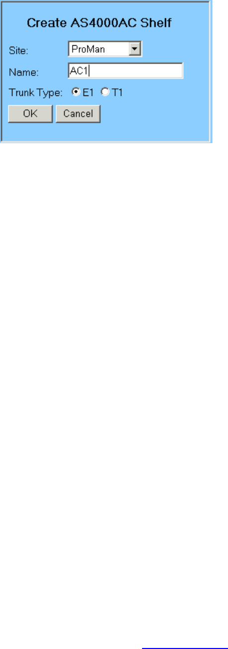
Printed Documentation
96
3. Select the site.
4. Enter name. The name must be unique within the network or an error message is
displayed and the shelf is not created.
5. Click OK to add shelf to the database.
6. The shelf is displayed on the tree view
7. Move mouse pointer to the shelf icon and right click. Select configure from the menu.
8. Continue with 'Setting up AC Rack and Shelf Configuration' below
Setting up AC Rack and Shelf configuration
1. Click right mouse button over AUX card position 4 select and create a CTU card.
2. Create additional CTU cards in slots 5 and 6 if required.
3. Position mouse over CTU card position, click right mouse button and select Airspan
CTU Properties
4. Set up the CTU properties as detailed in the Netspan Section
5. Repeat for other CTU cards.
6. Click OK
Assign Access Concentrator Card Slots
1. Click right mouse button over AUX card positions 7-17 to create other AUX cards as
required (XTUs RTU and PTU and Compression Unit.
2. Select the card type to be created.
3. Repeat steps 1 to 3 for all cards to be installed in the shelf.
Configure AC Cards
1. For details on configuring the cards see the relevant topic in the Netspan section of
this manual
Configure AC Shelf properties
1. Make sure the SC software is at the correct release, and all cards can be seen on the
AC Shelf equipment view. If required download the appropriate software by following
the software download procedure (see Software Download)
2. Re-boot the Shelf by clicking the Reset Shelf button on the shelf controller view.

Setup and Test
97
Check Boot Sequence
1. SC card boots-up and displays the following LED sequence:
a. Red & green LEDs both ON
b. All LEDs OFF
c. Green LED FLASHING
d. Green LED ON
e. The red LED temporarily comes ON
2. All the cards on the shelf now boot-up.
3. The TU cards display the following LED sequence:
Note: The boot-up procedure for these cards takes approximately 7 minutes.
a. Red LED, amber LEDs & green surface mount LEDs all ON. Green LED
FLASHING
b. Red LED ON, green LED FLASHING, amber LEDs OFF & green surface mount
LEDs showing download progress. Building up in a column from the bottom as the
code is download.
c. Green LED ON, green surface mount LEDs indicate card configuration as shown
below
LED CTU XTU
1 Top OFF ON
2 ON OFF
3 OFF OFF
4 Bottom OFF OFF
4. The rest of the cards display the following LED sequence:
Note: The boot-up procedure for these cards takes a few minutes and will depend on
the specific card type.
a. Red LED ON & green LED FLASHING
b. Green LED ON
5. If the cards do not boot-up correctly, i.e. any of the cards display a flashing red or
continuous red LED only, follow the procedure in case of Card boot-up failure
6. The boot sequence is complete when the Sitespan reports the shelf as connected
ready. This can take some additional minutes after the LED indications on the shelf have
stabilised. Note The duration of the connection process to Sitespan will increase depending
on the size of the subscriber database and the number of cards fitted.
Alarm and Status Indications (Test 3)
1. Verify that the alarms and status indications (LEDs) on the system comply with those
detailed in the following tables.
Note: The following tables are set in order of appearance on the front of the card
reading from top to bottom.
XTU
Position
Colour Description Status

Printed Documentation
98
TOP
1 Red Card failure LED, which shall be alight if the
card self test fails, or if commanded by the
SC.
OFF
2 Green Card busy LED, to indicate live traffic is
present and should not be removed. ON
3 Red/yellow
E1/T1 port 1 Alarm *
4 Red/yellow
E1/T1 port 2 Alarm *
5 Red/yellow
E1/T1 port 3 Alarm *
6 Red/yellow
E1/T1 port 4 Alarm *
7 Red/yellow
E1/T1 port 5 Alarm *
8 Red/yellow
E1/T1 port 6 Alarm *
9 Red/yellow
E1/T1 port 7 Alarm *
10 Red/yellow
E1/T1 port 8 Alarm *
LED Yellow if 2Mbit/s is being received with some other alarm condition. (e.g. remote
alarm or sync fail) being sent, Red if 2Mbit/s not received..
PTU
Position Colour Description Status
TOP 1 Red Card failure LED, which shall be alight if the card
self test fails, or if commanded by the SC. OFF
2 Green OK card is active. ON
3 to 8 Not used OFF
9 Orange
100 Mbit/s See
Note
10 Orange
Active (Ethernet Present) OFF
11 Orange
Full (12 RWs allocated) OFF
12 Green Packets being Received OFF
13 Green Packets Transmitted OFF
14 RED Ethernet Collisions ON
Note the LED is on when connected at 100Mbit/s and off at 10Mbit/s
CU
Position
Colour
Description Status
TOP
1 Red Card failure LED, which shall be alight if the card
self test fails, or if commanded by the SC. OFF

Setup and Test
99
2 Green Card busy LED, to indicate live traffic is present
and should not be removed. OFF
SC
Position
Colour
Description Status
TOP
1 Red Card failure LED, which shall be alight if the card
self test fails OFF
OK Card is Active.
PSU
Position Colour
Description Status
TOP 1 Red FUSE FAIL: Illuminated if either input fuse has
blown. OFF
2 Green OK Card is Active. ON
3 Red I/P A FAIL input voltage A (BATTNEG0) not
present OFF
4 Red I/P B FAIL input voltage B (BATTNEG1) not
present OFF
5 Red O/P OVERLOAD. OFF
6 Red O/P UNDERLOAD OFF
Access Concentrator Shelf Card LED Indications.
Self Test (Test 4)
1. Select CTU card on shelf view double click the card, or click right mouse button and
select Airspan (card type) View
2. Execute the self test function (using Netspan) on each CTU card and ensure that it
passes. Replace any faulty cards.
Test CTU cabling to the DDF E1 Cards
1. Using Netspan create a CT rack with a dummy modem shelf.
2. From the Edit AC Shelf Properties screen assign E1-1 to the newly created CT shelf.
3. A red alarm should appear on the CTU card for the E1 activated.
4. Loopback TX to RX for the E1 (T1) at the DDF. Check that the alarm clears (the
amber remote alarm is lit for several seconds before clearing).
5. Reassign the CT shelf to E1-2, E1-3 and E1-4 in turn and repeat steps 3 and 4 (E1-5
to E1-8 for 120ohm connection).
6. Repeat steps 1 to 5 for CTUs in slots 5 and 6 if fitted.
Test CTU cabling to the Distribution Frame (DDF) GR303 Cards.
Printed Documentation
100
1. Using Sitespan create a CT rack with a dummy modem shelf.
2. From the Edit AC Shelf Properties screen assign T1-1 to the newly created CT shelf.
3. A red alarm should appear on the CTU card for the T1 activated.
4. Loopback TX to RX for the T1at the DDF. Check that the alarm clears (the amber
remote alarm is lit for several seconds before clearing).
5. Reassign the CT shelf to T1-2*, T1-3, T1-4, T1-5, T1-6, T1-7 and T1-8 in turn and
repeat steps 3 and 4.
6. Repeat steps 1 to 5 for CTUs in slots 8 and 9 if fitt
Test XTU cabling to the DDF
1. Test one XTU at a time.
2. Activate all E1s/T1s for the chosen XTU card.
3. Check that 8 red LEDs appear on the front of the card (Netspan should also indicate
the E1/T1 alarm.)
4. Loopback each E1 in turn and check that the corresponding alarm for that channel is
cleared. (Note: the amber remote alarm is illuminated for several seconds before
clearing.)
5. Remove all jumper links and disable all E1s/T1s.
6. Repeat steps 2-5 for each XTU fitted.
Connecting the AC to the Network
(this section applies only if the AC has been configured using a local Laptop PC)
1. Ensure the NMC administrator has entered all the AC shelf configuration in the
Netspan/Sitespan Server.
2. Within the AC Shelf Properties window, enter the
Port: (should be the NMC PC COM port the AC shelf is connected to)
TEI: (should be set to the pre-determined setting allocated at the planning stage)
Leave other data fields unchanged.
3. Select OK to complete the configuration process.
4. DISCONNECT THE LAPTOP PC CONNECTION TO THE AC SHELF AND
RECONNECT THE NMC CONNECTION TO THE SHELF.
5. Call in the NMC and ensure the AC shelf is seen at the NMC system. From the Shelf
Object List view, the AC shelf should be in CONNECTED and DOWNLOADING state.
Connect E1s/T1s to the Switch or Cross-Connect at the DDF
1. If V5.1 interface is being used then the NMC administrator should enable the V5.1
interface. From the AC shelf equipment view, select the XTU card and use Edit-
>AS4000 DA V5.1 XTU
2. Connect the required E1s/T1s to the Switch or Cross-Connect using jumper cables at
the DDF.
3. All the E1/T1links should be enabled on Netspan at the NMC.
4. From the AC shelf equipment view, double click on the XTU card. This will open the
card view window. Check the E1/T1 connection to the switch is working; E1/T1-Loss
of Signal and E1/T1- Loss of FA alarms are cleared.
Setup and Test
101
5. On V5.1 cards, from the corresponding E1/T1, select Switch to New and then Re-
establish to activate the V5.1 interface with the switch. If the V5.1 interface is not
indicated as active in the XTU Card View the switch authority must be contacted .
6. On V5.2 cards from the corresponding E1/T1, select Switch to New. If the V5.2
interface is not indicated as active in the XTU Card View the switch authority must be
contacted.
7. On CAS systems check alarms are clear.
This concludes the setting up at the access concentrator. The CT site can now be
commissioned.

Printed Documentation
102
Access Concentrator Rack Commissioning Test Results
Please photocopy test results sheet for use with each system
CUSTOMER:
SITE LOCATION:
RACK ID:
ENGINEER:
DATE:
1. Commissioning Test Results
Test Equipment Calibration
Item
Description Model
Serial
No Calibration
Date
1 Digital
Multimeter
Serial Number and Rev Level Record
Rack ID
AC Shelf 1 Card Type Serial Number Rev Level
PSU 1 PSU
PSU 2 PSU
SC SC
AUX 1
AUX 2
AUX 3
AUX 4
AUX 5
AUX 6
AUX 7
AUX 8
AUX 9
AUX 10
AUX 11
AUX 12

Setup and Test
103
AUX 13
AUX 14
Rack ID
AC Shelf 2 Card Type Serial Number Rev Level
PSU 1 PSU
PSU 2 PSU
SC SC
AUX 1
AUX 2
AUX 3
AUX 4
AUX 5
AUX 6
AUX 7
AUX 8
AUX 9
AUX 10
AUX 11
AUX 12
AUX 13
AUX 14
Test Results
Rack ID
TEST
# TEST LIMIT RESULT
Site Inspection & Verification
T1/E1 Shelf 1

Printed Documentation
104
Cabling
Shelf 2
System Commissioning Tests
Exchange DC Voltage Supply
1
Test
1a
Exchange DC Voltage Supply
2
-21.8 to -60.0V DC
Exchange DC Voltage Supply
1
Test
1b
Exchange DC Voltage Supply
2
-21.8 to -60.0V DC
5V DC 250mV
3.3V DC +0mV-300mV
AC Shelf 1 PSU1
2.1V DC+0mV-100mV
5V DC 250mV
3.3V DC +0mV-300mV
AC Shelf 1 PSU2
2.1V DC+0mV-100mV
5V DC 250mV
3.3V DC +0mV-300mV
AC Shelf 2 PSU1
2.1V DC+0mV-100mV
5V DC 250mV
3.3V DC +0mV-300mV
Test
2
AC Shelf 2 PSU2
2.1V DC+0mV-100mV
TEST
# TEST LIMIT RESULT
Power Up and Self Test
AC Shelf 1
Alarms and
Indications
PSU 1
PSU 2
SC Card
AUX Cards (if
fitted)
Pass /Fail
Test
3
AC Shelf 2
Alarms and
Indications
PSU 1
PSU 2
SC Card
AUX Cards (if
fitted)
Rack ID

Setup and Test
105
TEST
#. TEST RESULT
SC Card
AUX 1
AUX 2
AUX 3
AUX 4
AUX 5
AUX 6
AUX 7
AUX 8
AUX 9
AUX 10
AUX 11
AUX 12
AUX 13
AC Shelf 1
System Configuration
Self test from Netspan
AUX 14
SC Card
AUX 1
AUX 2
AUX 3
AUX 4
AUX 5
AUX 6
AUX 7
AUX 8
AUX 9
AUX 10
AUX 11
AUX 12
AUX 13
Test 4
AC Shelf 2
System Configuration
Self test from Sitespan
AUX 14

Printed Documentation
106
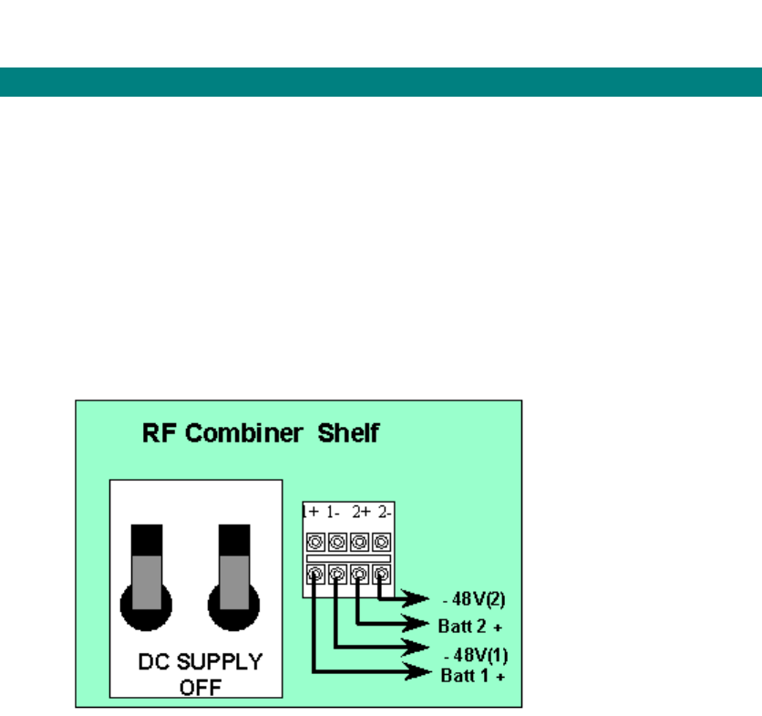
Setup and Test
107
AS4000 CT Setup and Test
Turn-Up and DC measurements
Before commencing the turn-up of the rack, check that the serial number and Rev levels
of all cards have been entered into the test form.
Disconnect the Antenna.
Rack Turn-Up and Measuring Input Voltage (Test 1a)
This section describes the procedure for measuring and connecting DC to the rack,
checking that the cards have the correct alarm indications on power-up and measuring the
PSU output voltages.
Using the DMM measure and record the Exchange DC voltage supply across the input
terminals ( 1(+) & 2 (-).for Supply 1 and 3(+) & 4 (-).for supply 2). Check that the polarity is
correct and ensure that the voltage measured complies with the site nominal voltage and
is within the limits specified on the test results sheet.
Switching on the racks. (Test 1b)
CT Rack: Combiner Shelf
Place one PSU in the shelf. Switch the CT Combiner Rack ON by placing one breaker on.
The two breakers duplicate power to each shelf and the shelves will still function if one
power supply fails though the LED indicators on the power supplies will not be on. The
PSU should show a amber LED and the fail LED. Switch on the second breaker and the
Red LED should extinguish.
Switch off and place the second PSU in the shelf and repeat the process described in
paragraph 1.
Using the DMM check that the DC voltage supply across the input terminals (1+ & 1- for
Supply 1 and 2 + & 2- for supply 2) is still within the specified limits and record on the test
results sheet.
Measure the DC voltage at the front panel test points on each of the PSUs on the RF
Combiner Shelf. Ensure that the voltage measured is +13.5V DC +/- 500mV. Switch both
breakers off. Record the result.
Place a PA into the shelf to provide a load. Switch both breakers on and measure and
record the DC voltage at the o/p of each PSU.
Using the DMM, measure a the DC voltage at the front panel test points on each of the
PSUs on the RF Combiner Shelf. (Figure 35)
Ensure that the voltage measured is +13.5V DC +/- 500mV.
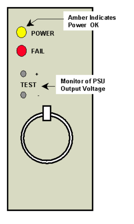
Printed Documentation
108
Combiner Shelf PSU.

Setup and Test
109
Commissioning the Central Terminal
Setting up Site Configuration on Netspan
This procedure is used to set-up the Central Terminal for commissioning and does not require
the back-haul to the Access Concentrator Site to be installed.
To commission the AC Shelf the Shelf must be either
connected via an RS232 interface to a Sitespan server on a Laptop PC. However the
settings made during the setup process must be transferred to the NMS Netspan
before it server is connected. or values set within the shelf during this process will be
overwritten by Netspan when it is connected as the values stored at the AC will be
written into the SC Shelf Controller of the shelf.
connected via an RS232 interface to a Sitespan server located with and connected to
the Netspan Server Machine.
connected via the backhaul to the AC that is connected to the Sitespan Server.
Physically inspect the rack and check that the details of the serial numbers and rev levels
have been recorded when the cards were installed. Check that cards have not changed since
installation. If cards have changed add details to the test form.
Before the commissioning of the CT racks, the system should be built using Netspan or
Sitespan Version 7.15 or later be installed on the dedicated PC (Laptop).
For details on setting up Netspan and the Sitespan server interface see topic in the
Netspan section. Note Always check that the version of Netspan matches the revision level
of the Netspan at the management system and is suitable for the version level of the SC card
application and boot code in the shelves to be commissioned.
Setting the TEI and Baud Rate for Sitespan Connection
1. Connect PC using AS7030 SiteStart software to the LAT port on the front of the shelf
controller of the Shelf being commissioned..
2. Set the TEI to the value designated during system planning. The TEI number must be
unique to the Network managed by Sitespan.
3. Set the Baud Rate for connection. The same rate must be set when setting up CT
Shelf Properties later in this commissioning process.
4. Build the system using Sitespan or Netspan (see Sitespan/Netspan user guide)
Create Site and Rack
Create Modem Shelves
Create DTU Card
Configure Modem Shelf
Connect Netspan to the Modem shelf under test.
Check that Sitespan is communicating with the shelf. The SC alarm on Sitespan clears and
shows downloading and then connected ready. In the shelf view all cards should be green.
CT Shelf Controller Software Downloads
1. Verify that the required software is loaded onto the CT shelf

Printed Documentation
110
2. If required download the appropriate software by following the software download
procedure (see Software Download)
3. Re-boot the Shelf by clicking the Reset Shelf button on the shelf controller view.
Check Boot Sequence
1. SC card boots-up and displays the following LED sequence:
a. Red & green LEDs both ON
b. All LEDs OFF
c. Green LED FLASHING
d. Green LED ON
e. The red LED temporarily comes ON
2. All the cards on the shelf now boot-up.
3. The DTU cards should display the following LED sequence:
Note: The boot-up procedure for these cards takes approximately 15 minutes.
a. Red LED, amber LEDs & green surface mount LEDs all ON. Green LED
FLASHING
b. Red LED ON, green LED FLASHING, amber LEDs OFF & green surface mount
LEDs showing download progress.
c. Green LED ON, green surface mount LEDs indicate card configuration as shown
below
LED DTU
1 Top OFF
2 OFF
3 ON
4
Bottom
OFF
The rest of the cards display the following LED sequence:
Note: The boot-up procedure for these cards takes a couple of minutes
a. Red LED ON & green LED FLASHING
b. Green LED ON
If the cards do not boot-up correctly, i.e. any of the cards display a flashing red or
continuous red LED only, follow the procedure in case of Card boot-up failure
Note. Some early demo system and field trial T1 TU cards may fail to boot on initial
power up, and it may be necessary to unplug and re-insert the card to initiate the boot
sequence. If the card does not reboot then the Eprom in the card should be re-blown.
Alarm and Status Indications (Test 3)
1. Verify that the alarms and status indications (LEDs) on the system comply with those
detailed in the following tables.
Note: The following tables are set in order of appearance on the front of the card
reading from top to bottom.
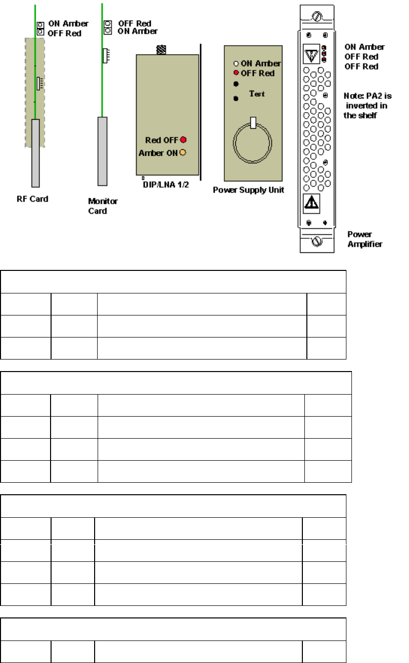
Setup and Test
111
RF Combiner Shelf
Low Noise Amplifier
Position Colour Description Status
Top 1 Amber Power/Module Status OK ON
2 Red Power Fault OFF
RF Card [RF]
Position
Colour Description Status
Top 1 Amber Power/Module Status OK ON
2 Red Power Fault OFF
Shelf Monitor
Position
Colour Description Status
Top 1 Red Power Fault/PA Module Fault OFF
2 Amber Power/Module Status OK ON
Power Amplifier[PA]
Position Colour Description Status
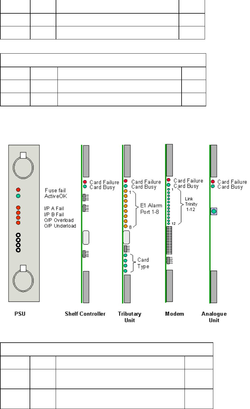
Printed Documentation
112
Top 1 Amber Power/Module Status OK ON
2 Red Power Fault/PA Module 1 Fault OFF
3 Red Power Fault/PA Module 2 Fault OFF
* PA 2 is inserted inverted and the alarm indicators are also inverted
Power Supply Unit [PSU]
Position
Colour Description Status
Top 1 Amber Power OK ON
2 Red Power Fail OFF
Table. RF Combiner Shelf Card LED Indications.
Modem Shelf Card LEDs.
In normal state all LEDs will
MODEM
Position
Colour Description Status
TOP
1 Red Card failure LED, which shall be alight if the
card self test fails, or if commanded by the SC.
OFF
2 Green Card busy LED, to indicate live traffic is
present and should not be removed. ON

Setup and Test
113
3 Green Link failure Trinity 1 OFF
4 Green Link failure Trinity 2 OFF
5 Green Link failure Trinity 3 OFF
6 Green Link failure Trinity 4 OFF
7 Green Link failure Trinity 5 OFF
8 Green Link failure Trinity 6 OFF
9 Green Link failure Trinity 7 OFF
10 Green Link failure Trinity 8 OFF
11 Green Link failure Trinity 9 OFF
12 Green Link failure Trinity 10 OFF
13 Green Link failure Trinity 11 OFF
14 Green Link failure Trinity 12 OFF
DTU
Position
Colour Description Status
TOP
1 Red Card failure LED, which shall be alight if the
card self test fails, or if commanded by the
SC.
OFF
2 Green Card busy LED, to indicate live traffic is
present and should not be removed. ON
3 Red/Yellow
E1/T1 port 1 Alarm *
4 Red/Yellow
E1/T1 port 2 Alarm *
5 Red/Yellow
E1/T1 port 3 Alarm *
6 Red/Yellow
E1/T1 port 4 Alarm *
7 Red/Yellow
E1/T1 port 5 Alarm *
8 Red/Yellow
E1/T1 port 6 Alarm *
9 Red/Yellow
E1/T1 port 7 Alarm *
10 Red/Yellow
E1/T1 port 8 Alarm *
LED Yellow if T1/E1 signal is being received with some other alarm condition. (e.g. remote
alarm or sync fail) being sent, Red if T1/E1 signal not received.
AU
Position
Colour
Description Status

Printed Documentation
114
TOP
1 Red Card failure LED, which shall be alight if the card
self test fails, or if commanded by the SC. OFF
2 Green OK Card is Active.. ON
SC
Position
Colour
Description Status
TOP
1 Red Card failure LED, which shall be alight if the card
self test fails OFF
OK Card is Active.
PSU
Position
Colour
Description Status
TOP
1 Red FUSE FAIL which shall be alight if either input
fuse has blown. OFF
2 Green OK Card is Active. ON
3 Red I/P A FAIL input voltage A (BATTNEG0) not
present OFF
4 Red I/P B FAIL input voltage B (BATTNEG1) not
present OFF
5 Red O/P OVERLOAD. OFF
6 Red O/P UNDERLOAD OFF
Self Test (Test 4)
Execute the self test function (using Netspan) on the DTU cards and ensure that they pass.
Replace any faulty cards.
System Soak
It is necessary that the system is powered up for at least two hours to allow for
temperature stabilisation before proceeding with the measurement of the TX power
commissioning
Note: If proceeding to commissioning the DACU should be powered up and allowed to
warm up for 30 mins prior to setting the RX sensitivity.
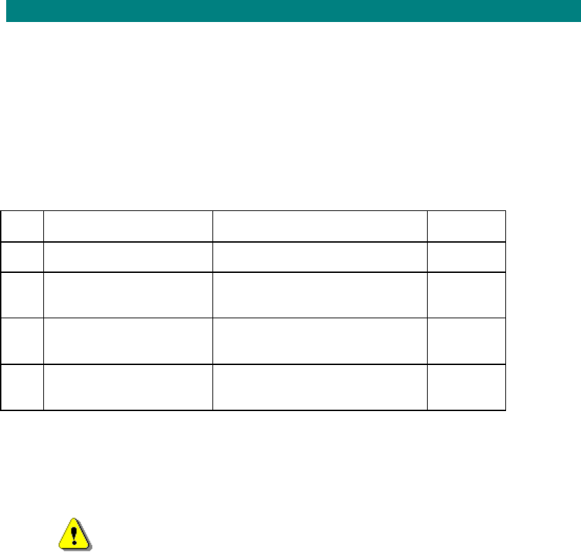
Setup and Test
115
Measuring Central Terminal TX Power
The recommended single user TX output power is +18dBm for 3.4-3.6GHz, +20dBm for 1.8-
1.9GHz, and +21dBm for all other bands. This procedure is used to measure the TX output
power when set up for 3 Users.
Note: If proceeding to commissioning the DACU should be powered up and allowed to warm
up for 30 mins prior to setting the RX sensitivity..
This procedure is for setting up AS4000 shelves only.
Tools and equipment needed.
Item
Description Recommended Model Quantity
1 50 ohm Termination 10W
ArraN9510 1
2 RF Power Meter Anritsu Sitemaster S400A or
Marconi 6970 1
3 Power Sensor Anritsu 560-7N50B or Marconi
6932 1
4 Attenuator for use with
Anritsu HP 8491 (N Type) 1
Test TX Output Power (Test 5)
Note: If adding a shelf to a rack that is already in service it is necessary to
remove any shelf sharing the power amplifier from service in order to make
power measurements. This is best done when traffic loading is at its lowest
In order to commission the output power of the rack, a Power Meter must be
connected via a power sensor to the N-Type connector on the DIP/LNA at the top of
the rack. Protect the meter by connecting a 30dB attenuator (HP 8491) to the output
of the DIP/LNA as the output power can exceed 33dBm.
1. Note: The output from shelves 1 and 2 is measured on DIP/LNA1. The outputs from
shelves 3 and 4 are measured on the DIP/LNA2. The port not under test should be
terminated with a 10W termination.
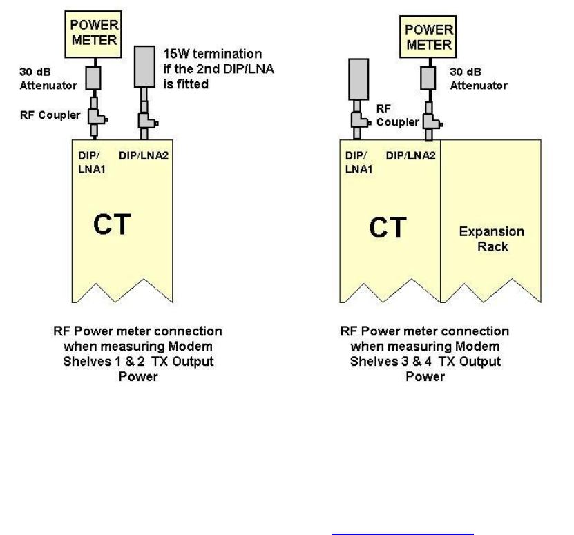
Printed Documentation
116
Figure Power Level measurement Test Set-Up
Measure the output of shelf 1. (This test is repeated for other installed shelves)
1. Remove the RF cards for all but the shelf being commissioned
2. Connect Sitespan to the shelf under test. See Connection to Sitespan
3. Open The DTU Card View and click the Commission Button. This button places the
shelf into an internal commissioning test mode. This button is clicked before the
commissioning procedure is started. This turns of the Link Acquisition and Call
Control Channels off.
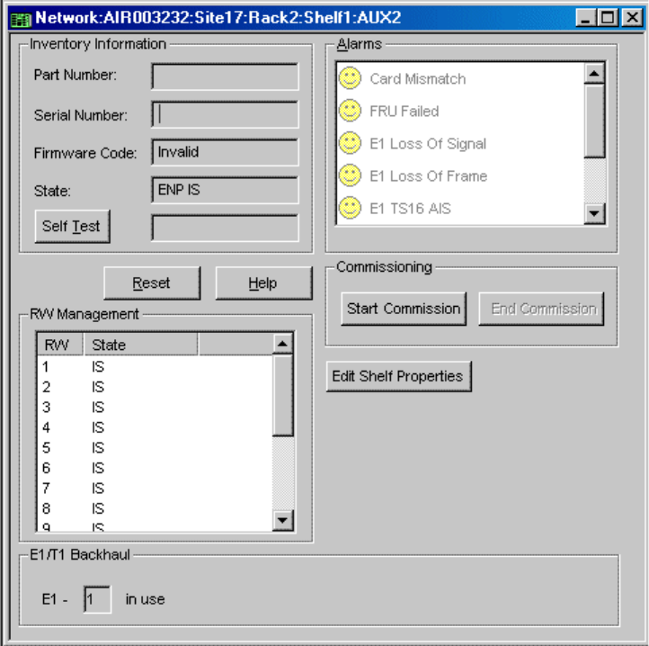
Setup and Test
117
4. Open the DTU card properties. Set any 4RWs to OOS160k and the remainder to
OOS (These can be selected from the by clicking the mouse on the state to cycle
through the options).
Printed Documentation
118
5. View the Modem Shelf Properties using Sitespan. Set the TX and RX gain to 0(zero)
6. Ensure that a 30dB attenuator is connected to the power sensor if required to protect
the sensor.
7. Calibrate/set-up power meter according to manufacturers instructions.
8. Connect the power sensor at the top of the rack as per diagram
9. Measure O/P power and ensure the level is less than -20dBm
10. Adjust TX Gain for the band of the system under test. Start with the TX gain set to
3300. Adjust the value up or down to obtain a reading as shown in the table below. This is
equivalent to 4 users at 160k. Remember to take into account the value of any attenuation
used to protect the meter.
Band Reading
1.8-1.9GHz +26dBm

Setup and Test
119
2.0-2.3GHz +27dBm
2.3-2.5GHz +27dBm
3.4-3.6GHz +24dBm
11. Set RW1 to OOS(160K) and all other RWs OOS
12. Measure the output power: ensure the level is as in the table below
Band Reading
±1dB
1.8-1.9GHz +20dBm
2.0-2.3GHz +21dBm
2.3-2.5GHz +21dBm
3.4-3.6GHz +18dBm
13. Repeat power reading for single RW OOS(160k), for all other individual RWs
14. Record the result (see Test Results)
15. On the DTU card view click the End Commissioning button (this re-activates RWs
14 & 15 and sets all RWs IS.
16. Repeat for all other modem shelves.

Printed Documentation
120
Procedure in case of card boot-up failure
Procedure in case of card boot-up failure
If the cards inserted into the shelf do not boot-up, the top red LED on the card will be either
continuously ON or FLASHING. The following steps should be followed:
1. Check cards are properly inserted into the shelf, in the correct positions
2. Reset the SC card using Netspan/Sitespan, under the card view.
3. The cards boot-up. If the cards do not boot-up try and reset the shelf backplane
configuration. Download the SetTUinv.txt to the SC. Ensure they are available before
continuing.
4. Disconnect Netpan from the shelf containing cards that will not boot-up.
5. Connect the LAT cable to the SC card
6. Send the text files for the correct shelf, one after another using Terminal.
7. Once completed, type the following:
TI 118
EA 118:0/119:0
ES 0
8. Wait 2 – 3 minutes for the process to complete.
9. Reset the SC by shorting Pins 2 & 3
10. Wait for 3 minutes: After 3 minutes the Shelf Controller has a green LED ON, and all
the other cards have FLASHING red LEDs
11. Re-Connect Netspan /Sitespan
12. The cards on the shelf boot-up. If the cards do not boot-up, then it is likely that one of
the cards is faulty. Try replacing one of the cards and starting the procedure again.
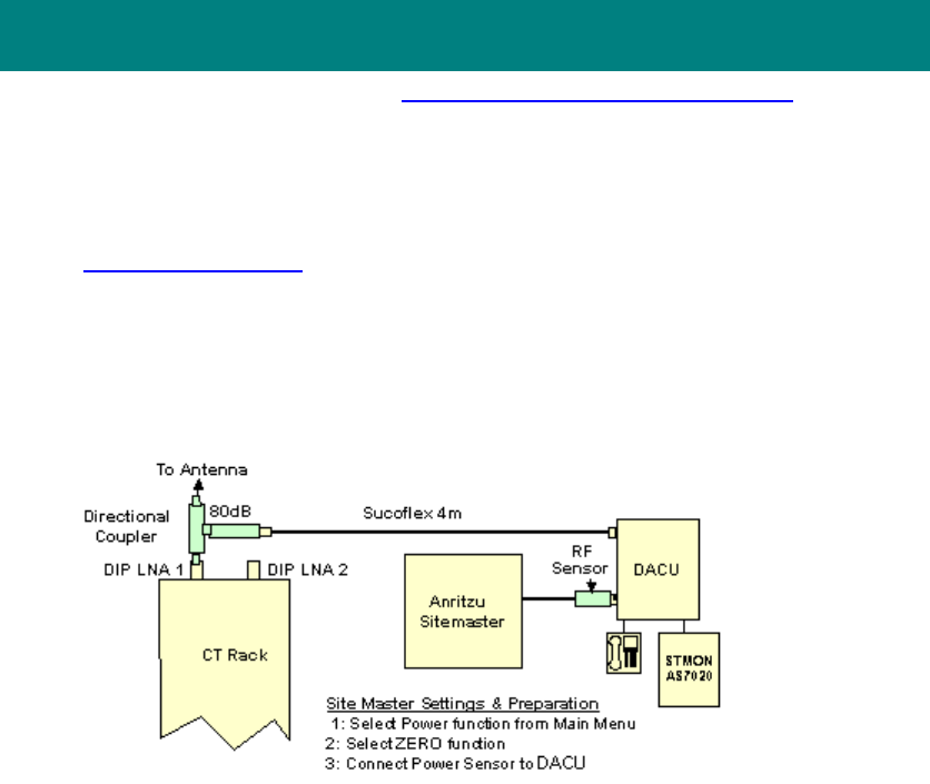
Setup and Test
121
Setting RX sensitivity using DACU 2.0-2.3GHz & 3.4-3.6GHz
Band
(Test 6) If a DACU is not available use Setting RX Sensitivity without DACU
Preparation for commissioning at the Central Terminal
1. The DACU should be powered up and allowed to warm up for 30 mins to achieve
stability prior to setting the RX sensitivity. For details on setting up the DACU see
Connecting the DACU
2. Enter the loss values in the DACU calibration chart for the relevant frequency See
chart below.
3. Calculate/determine total path loss and required DACU output power and hence
power meter reading.
4. Connect cables and equipment as per diagram below
5. Ensure that the commissioning button is off. This should have been done at the end
of the TX Gain set-up but it is prudent to ensure that it has been switched off. Switching off
resets the DTU card, reactivates RW14&15 for link acquisition, and sets all RWs in service.
Note: The DTU card view shows all of the RW codes, and their current state within the system
(i.e. OOS or IS).
6. Create an ST on Netspan. See Netspan Section
7. Configure test ST using AS7020STMON according to modem shelf properties to the
correct frequency, PN code and ID number.
8. Allow test ST to acquire link and net enter to “warm” state
9. Using the ST Line List, set loopback mode on both lines to enable 160k high rate
operation.
10. Measure the DACU o/p level
11. On Modem Shelf Properties, set RX gain to achieve required ST o/p level as
calculated in step 4 for –98dBm receiver sensitivity Adjust the 'RX Gain' by increasing and
decreasing the values.
12. Note: To start with, set the RX gain to around 2200. ( if value is reduced power goes
UP). The values may be set by typing in a new value or by using the up and down arrows at
the side of the box. The ST power changes in steps of approximately 0.7dB and the nearest
value to the required value. A single step on the gain value may not produce any change so
start with larger values and through a number of iterations home in on the correct setting.
Note: Levels are updated only when the OK button is clicked. Check the output power of the
DACU, and repeat until the output power matches that in the DACU Calibration Table.
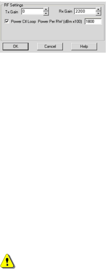
Printed Documentation
122
14. Record results in test results sheet
15. Power off the DACU.
16. Put all RWs back in service.
Restoring shelf connections
1. Remove the test equipment and connecting cables.
2. Replace the Shelf covers and the protective cap on the coupler.
3. Do not remove the Sitespan connection at this time.
Entering Test values into Netspan
The values of the TX Transmit and RX gain must be set into the Netspan at the Network
management Centre before the backhaul is connected to the CT, failure to do this results in
the TX power and RX sensitivity values being overwritten by the value stored in the Netspan
Server.
Connecting CT, AC and NMC
At this point, ensure the NMC has the site equipment created in the master database and the
V5.1 interface activated. It should show an alarm on the E1 connection to the CT shelf.
1. Contact the NMC administrator, and pass the CT shelf Transmit Power and Receiver
Level settings to the administrator for updating the master database.
Warning: When Netspan is reconnected to the CT the values of the TX and RX
levels stored at the NMC will be written to the SC of the modem shelf and Netspan
should not be reconnected until the NMC has updated its database with the correct
Transmit and receive level settings.
2. The CT shelf connected to the LAPTOP should be in ‘UNCONNECTED’ state. This is
because the shelf is expected to get its data from the remote management system.
3. Reconnect the E1/T1 links to the CTUs/DTUs.
4. At the AC Connect Netspan backhaul to the NMC. If using a router fit RS232 9 way
to Async RJ45 adapter to the Netspan port used to backhaul to the server. Connect Sitespan
Port 1 (AC Backplane) to Management Network (ports allocated on Cisco Router).
5. Call the NMC and ensure the commissioned shelf is in ‘connected’/ ‘downloading’
state and the E1/t1 alarm on the CTU is cleared.
6. Remove Modem card and check that the alarm is seen in Netspan’

Setup and Test
123
Setting RX Sensitivity without DACU
Tools and equipment needed.
Item
Description Recommended Model Quantity
1 Digital Multimeter Fluke 77 1
2 ST Test Unit, SIU with Modified Antenna at
appropriate band 1
3 30dB Attenuators; 5W Mini Circuits: BN-N30W5 2
4 30dB Attenuators; 2W M/A-COM:2082 6044 30:2W 2
5 Two Way Power
Divider Mini Circuits: ZAPD-4-S 1
6 50 ohm Termination
10W Arra N9510 1
7 Adaptor; N-SMA Huber & Suhner 33N-SMA-50-1 1
8 Adaptor; N-SMA Huber & Suhner 31N-SMA-50-1 1
9 Huber & Suhner Sucoflex 104; 0.5m 2
10
Co-ax Cables
Huber & Suhner Sucoflex 104; 4.0m 1
11 Cable SMA-MCX Huber & Suhner 30-05918-10 1
12 RF Power Meter Marconi 6970 1
13 Power Sensor Marconi/RFI 6970&5 6932/900 1
RX Sensitivity (Test 6)
1. To set the receive sensitivity, first set up a test network for the band under test as
shown below. The figure below show the test equipment connected directly to the
outputs of the DIP/LNA and DIP/LNA2 as would be the case for systems without a
RFcoupler.
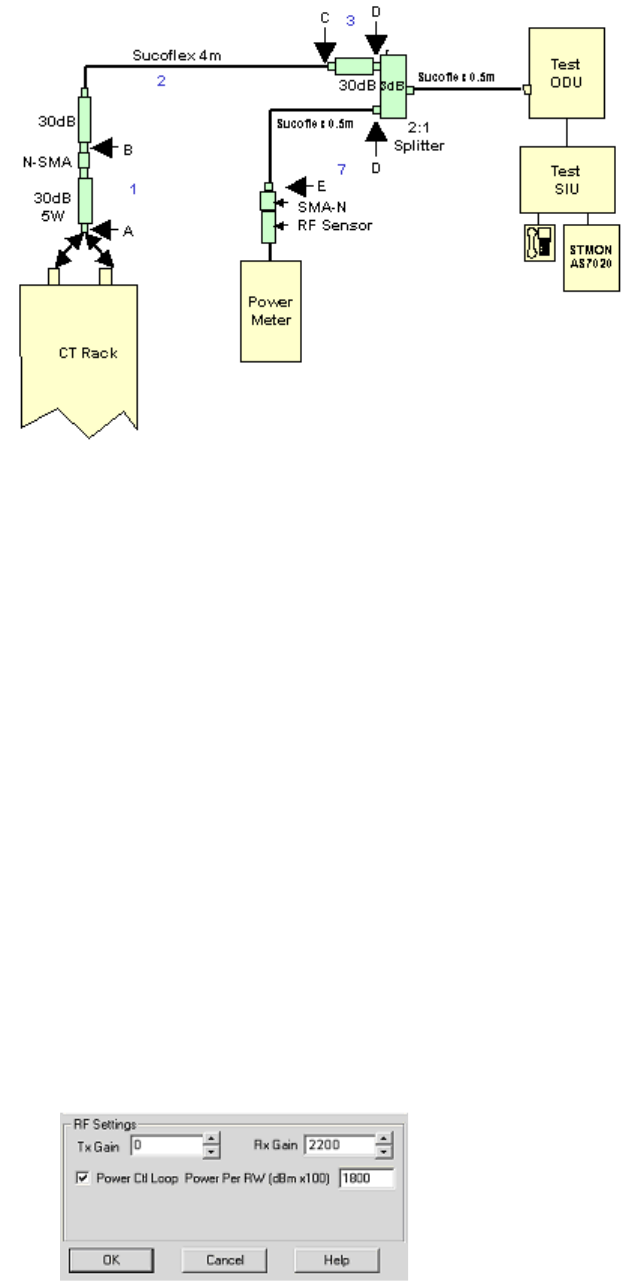
Printed Documentation
124
Test Set-up
2. Measure and calibrate the loss of all components as per diagram above:
3. Measure (1)A-B, (2)B-C, (3)C-D and (7)D-E.
4. Enter values in calibration chart for the relevant frequency.
5. Calculate/determine overall path loss and required ST output power and hence
required power meter reading.
6. Connect cables as per diagram above.
7. Ensure that the commissioning button is off. This resets the DTU card, reactivates
RW14&15 for link acquisition, and sets all RWs in service
8. Create ST on AC ST list
9. Configure test ST using AS7020STMON according to modem shelf properties to the
correct frequency, PN code and ID number.
10. Allow test ST to acquire link and Net Enter to “warm” state
11. From ST properties, set loopback mode to enable 160k high rate operation
12. Measure ST TX o/p level
13. On Modem Shelf Properties, set RX gain to achieve required ST o/p level as
calculated in step 4 for –98dBm receiver sensitivity
Note: To start with, set the RX gain to around 2200 and click right mouse
button at the side of the RX Gain Box to increase and decrease reading at the
power meter. Check the output power of the ST, and repeat until the output
power reaches the required level
14. Record results in test results sheet
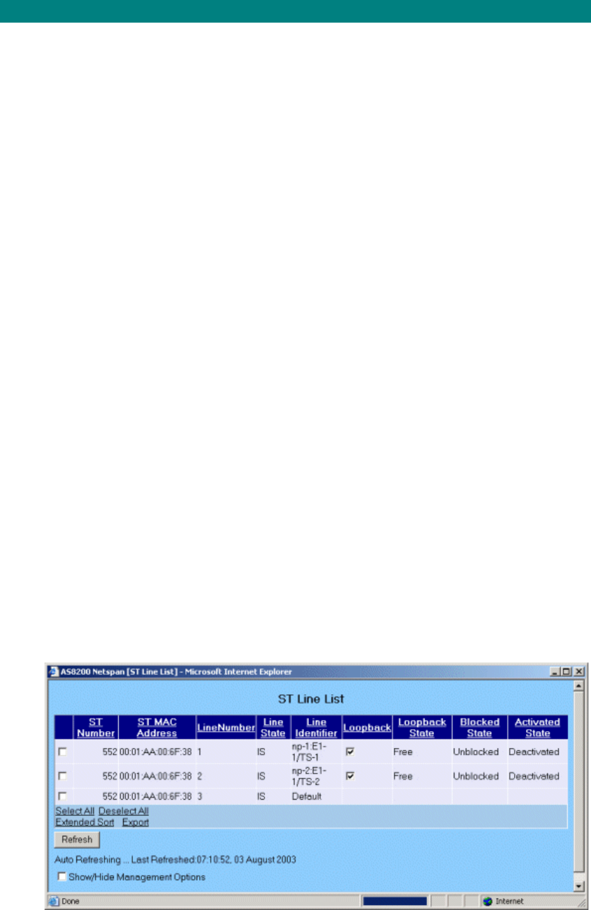
Setup and Test
125
BER Test
The BER test is best done from the network management centre but if a management centre
backhaul has not yet been established the test may be performed at the AC site and should
be set up by connecting Local Netspan/Sitespan to AC Rack, building site locally and create
subscriber.
Setting up system tests at the Access Concentrator.
Create CAS XTU in a spare slot (slot 10 if spare).
Create CAS subscriber in Sitespan. Note the timeslot and E1 link used.
Fit CAS TU card to the shelf in the configured slot. Fit CAS TU card to the shelf in the
configured slot.
Setting up Test ST.
To perform overall system tests a test ST should be set up. The ST should be located
1 to 5 km from the CT in the centre of the lobe served by the CT. Set up using details
to match the RF channel, PN code and ST-ID for the CT sector to be tested.
Screen captures of the RF analysis may be taken and pasted into a document for
confirmation of the relative signal strengths.
Check for the ST to acquire a link and use STMON to ensure that the frequency
acquired is that of the CT and not that of an adjacent signal. (see STMON User Guide
for details of checking the channel.)
For Information on setting up a subscriber terminal see 605-0000-505. Subscriber
Terminal installation and commissioning.
Measuring BER
This process can be carried out at the Access Concentrator and loopback at the ST or
if using a Data ST the test may be performed at the L series ST and a loop applied at
the Exchange
a) Testing at the Access Concentrator
Connect BER Tester to E1 in link on the shelf backplane (or Type 43 converter module
if used) set above and inject a 64K Pseudo Random Pattern 215-1in the timeslot set
above.
Put a Loop on the ST from Netspan (In the ST Line List. check the Loopback box and
click OK).
Note: The loopback is dropped if the link fails or the ST power is cycled To reapply the
loopback the loopback tick box should be cleared and the OK button clicked. The
loopback should then be re-applied by re-checking the loopback tick box and clicking
the OK button.
Printed Documentation
126
The presence of the loopback should be seen at the BER test set. Inject 1 error into
the test signal and observe it on the incoming signal to check that errors are detected.
Start and stop the test to clear the injected error.
Observe the return signal on the T1/E1 out to establish that the link is error free. Run
BER test for 1 Hour.
On completion of the test remove the loopback (open the Edit DA ST window and click
the Loopback box to remove the tick and click OK.)
Delete CAS subscriber in Sitespan, and delete CAS XTU.
b) Testing at the Subscriber Terminal if L Series SIU used.
An alternative method of testing the BER of a link from a CT to an ST is to provide a
hard wired loopback on a selected E1/T1 port on a Data XTU Card at the AC site. By
using an ST-L128 or ST-l64, 128kbit/s or 64kbit/s data rates may be tested using a
BER tester at the ST location. The advantage of this method is that there is no need to
have a person at both the AC site and the ST test location
Note. A suitable data cable from the BER test set is required. Most BER test sets
provide V.35 or X.21 synchronous interface options.
Power for a prolonged test may be a problem in field locations . An inverter running
from a vehicle 12V supply may be used for tests of up to 1 hour with the ST powered
directly from the Vehicle battery Place a physical loop on the E1/T1 at the
AC/Exchange.
At the AC site: Loopback E1 link on Data XTU card. (loop on shelf backplane or DDF)
At the Subscriber Terminal: Connect BER test set to the ST.
The presence of the loopback should be seen at the BER test set. Inject 1 error into
the test signal and observe it on the incoming signal to check that errors are detected.
Start and stop the test to clear the injected error.
Observe the return signal on the E1/T1 out to establish that the link is error free. Run
BER test for 1 Hour.
On completion of the test remove the loopback and re-connect the E1/T1.
Delete test data subscriber in Netspan.

Setup and Test
127
Setting the System into Service
Checking alarms and connections to Netspan
At the AC Test the RS232 disconnect alarm by disconnecting the adapter on Sitespan port I.
Pull card and check alarm is visible at NMC.
At the NMC set the free list entries. For details on setting free list entries see the Netspan
Help File
Note System Optimisations to the configuration that improve Net entry time
Ensure that the number of net-entry channels is set to around 6 for a shelf running
medium/ large deployments of voice service. The only constraint to be borne in mind is
that each channel used for net-entry is not available for traffic, so you need to be careful
about not over-provisioning the number of net entry channel if the shelf has a large
proportion of data / ISDN STs (which operate in a fixed-assigned mode).
Make certain that any STs that are created in the database before deployment are
marked 'out-of-service'. If they're not, on every cycle through the database, the system is
trying to net-enter STs that don't exist.
Test Call
1. Connect the AC port to Switch (ensure V5.1 link and cards configured).
2. Create a V5.1 DA Subscriber Terminal using Netspan and place the ST in service.
Check L3 address unblocked and define phone number.
3. Configure the test ST with the ST Id PN number RF channel and phone number (as
set at NMC).
4. Wait for ST to acquire a link (STMON can be used to monitor progress). Check for
dialtone.
5. Using a telephone make test call from the test ST over the system. Check for both
way transmission and absence of noise and interference.
6. Solicit an incoming call from the NMC or another phone and again check the quality
of the call
The tests should be completed for all other shelves commissioned on the same base
station.
At the completion of all tests remove all test cards from the shelf
BER Tests
See Topic BER Tests
Packet Testing
See Topic Packet System Testing
Site inspection and test card removal
When the BER and call tests are completed for all other CT shelves relating to an AC site
(may have 1 or more AC shelves) remove all test cards from the AC shelf and delete all test
STs from Netspan
At the AC and CT sites check all work areas are free of debris i.e. cable off-cuts, braid, dust
and packaging and that the site is as found.
This completes the system commissioning

Printed Documentation
128
AS4020 CT Setup and Test
AS4020 Menu Map
The system parameters are set from the front panel of the AS4020
The chart below shows the menu layout
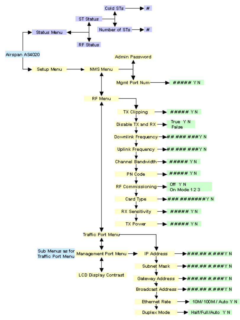
Setup and Test
129

Printed Documentation
130
AS4020 error messages
The List below shows error message codes that are reported to the front panel of the AS4020
Code Meaning
0 the image being loaded has a magic number that
identifies it, this number has been corrupted.
1 the image has a build information header, (not the
Airspan file header), attached containing which has
an associated checksum, this is corrupted.
2 the image being loaded has a checksum calculated
that is different to the one stored in the header.
3 the image has been built for the wrong architecture.
4 the image being loaded is not a kernel image.
5 the image has been compressed using an
unrecognised method.
6 the image is of the wrong type, not a standalone or
multi-image.
7 the image loader has exited due to internal error.
8 shutdown initiated from boot code.
9 the flash file system is corrupted.
10 the image being loaded is not a RAMDISK.
11 CPU fan failure detected.
12 router fan failure detected.
13 over temperature detected. see Note 1
14 kernel panic
Note 1
If a "system halted, code=13" message on the LCD this can mean more than just a cpu fan
failure, to determine which fan/thermal error caused the halt, run up system while logging the
output from the front panel port marked 232, the last message before the system stops should
be one of these :-
"cpu temp = XXXdegC, shutting system down...."
"router temp = XXXdegC, shutting system down...."
"summer temp = XXXdegC, shutting system down...."
"psu temp = XXXdegC, shutting system down...."
"cpu fan slow, shutting system down...."
Additionally, if a chassis fan is misbehaving the following message is displayed :-
"chassis fan X slow, setting all other fan pwms to max"
where XXX is some appropriate value.

Setup and Test
131
Set Traffic/Management Ports
The traffic port connects to the Ethernet connecting to the internet service provider and the
management port connects to the Netspan server.
Enter the following parameters from the front panel of the AS4020. The values are
determined by the server that the network is connected to.
IP address = in the form xxx.xxx.xxx.xxx i.e 192.254.130.030
Subnet mask = in the form xxx.xxx.xxx.xxx i.e 255.255.000.000
Gateway address = may be used if management is on another network else set to
000.000.000.000
Broadcast Address = used for broadcasts and would usually be the network address
and mask so for the IP network above would be 195.254.255.255 but this information
should be provided by the network administrator.
Ethernet Rate. Set to the rate dictated by the network, if in doubt set to Auto
Duplex Mode

Printed Documentation
132
Set NMS Menu
Management Port Num
Port Number used to connect to Netspan
Admin Password
Password protection for the AS4020. When set only authorised persons can make changes to
the AS4020 configuration. If changes are made Via Sitespan a password is requested if set. If
no password is set Netspan still requests a password but any entry will be successful in
allowing access to the configuration.
Setup and Test
133
Set TX Power
The recommended single user TX output power (QPSK/16QAM) is +18dBm for 3.4-3.6GHz,
+20dBm for 1.8-1.9GHz, and +21dBm for all other bands. This procedure is used to measure
the TX output power when set up in commissioning mode 1.
System Soak
It is necessary that the system is powered up for at least two hours to allow for
temperature stabilisation before proceeding with the measurement of the TX power
Tools and equipment needed.
Item Description Recommended Model Quantity
1 50 ohm Termination
10W ArraN9510 1
2 RF Power Meter Anritsu Sitemaster S400A or
Marconi 6970 1
3 Power Sensor Anritsu 560-7N50B or Marconi
6932 1
4 Attenuator for use with
Anritsu HP 8491 (N Type) 1
Test TX Output Power (Test 5)
Note: If adding a shelf to a rack that is already in service it is necessary to
remove the RF card for any shelf sharing the power amplifier in order to make
power measurements. This is best done when traffic loading is at its lowest
In order to commission the output power of the rack, a Power Meter must be
connected via a power sensor to the N-Type connector on the DIP/LNA at the top of
the rack. Protect the meter by connecting a 30dB attenuator (HP 8491) to the output
of the DIP/LNA as the output power can exceed 33dBm.
Note: The output from RF cards 1 and 2 is measured on DIP/LNA1. The output from
RF cards 3 and 4 is measured on the DIP/LNA2. If the AS4020 shelf has been added
to an existing rack then the RF card used must be inserted prior to measuring the shelf
power. The port not under test if not connected to an antenna should be terminated
with a 10W termination.
Measure the output of AS4020. (This test is repeated for other installed AS4020
shelves)
Connect RF meter via a 30dB attenuator on the antenna port to protect the power sensor
from damage.
Configure the AS4020 using the menus on the front panel. From the Top Menu >Setup
Menu >RF Menu set the following values:
Note: The PN code should always be set prior to entering commissioning mode.
RF Menu
TX Clipping 00101
Disable TX and RX False
Downlink Frequency Enter DL frequency kHz with leading 0 e.g 03522751

Printed Documentation
134
Uplink Frequency Enter UL frequency kHz with leading 0 e.g 03522651
Channel Bandwidth 00002 (=3MHz)
PN Code PN code as supplied**
RF Commissioning Mode 1 Note: If in commissioning mode the top menu
displays RF commissioning alarm
Card Type enter card type ( See number on RF card)
RX Sensitivity 02500
TX Power 03000
** The commissioning procedure described in this document is not restricted to any
particular RF channel or PN code. However the user should make sure that both the CT
and ST are programmed with identical RF channel and PN code. At the CT end, the RF
channel and PN code can be selected from the front panel in RF menu. In system
operating Release 7.2x once the user changes the PN code he needs to re-enable the
commissioning mode in order for this change to take effect properly. Release 7.30
however fixes this problem and the user should be able to change the PN code without
the need to re-enable the commissioning mode.

Setup and Test
135
RF Card Cross Reference Chart
RF Card Part
Number AS4020 Card
Type Band
605-0010-296 303-0087-904 3.4-3.6 Plan 13 X6
605-0010-092 303-0087-920 3.4-3.6 Plan 1 X1
605-0010-093 303-0087-920 3.4-3.6 Plan 1 X1
605-0010-102 303-0087-922 3.4-3.6 Plan X3
605-0010-103 303-0087-922 3.4-3.6 Plan X3
605-0010-237 303-0087-923 3.4-3.6 Plan 2 X4
605-0010-238 303-0087-923 3.4-3.6 Plan 2 X4
605-0010-294 303-0087-924 3.4-3.6 Plan 13 X6
605-0010-322 303-0087-925 3.4-3.6 Plan 10 X7A
605-0010-073 303-0093-900 2.0-2.3 Plan C2
605-0010-074 303-0093-900 2.0-2.3 Plan C2
605-0010-069 303-0093-902 2.0-2.3 Plan C1
605-0010-070 303-0093-902 2.0-2.3 Plan C1
605-0010-077 303-0093-904 2.0-2.3 Plan C3
605-0010-078 303-0093-904 2.0-2.3 Plan C3
605-0010-081 303-0093-906 2.3-2.5 Plan S1
605-0010-082 303-0093-906 2.3-2.5 Plan S1
605-0010-075 303-0093-920 2.0-2.3 Plan 2 C2
605-0010-076 303-0093-920 2.0-2.3 Plan 2 C2
605-0010-071 303-0093-922 2.0-2.3 Plan 1 C1
605-0010-072 303-0093-922 2.0-2.3 Plan 1 C1
605-0010-079 303-0093-924 2.0-2.3 Plan C3
605-0010-080 303-0093-924 2.0-2.3 Plan C3
605-0010-352 303-0093-925 2.0-2.3 Plan 5 C4
605-0010-083 303-0093-926 2.3-2.5 Plan S1
605-0010-084 303-0093-926 2.3-2.5 Plan S1
605-0010-163 303-1041-900 1.8-1.9 Plan P
605-0010-122 303-1041-920 1.8-1.9 Plan P
605-0010-295 303-1041-921 1.7-1.8 Plan P
605-0010-330 303-1070-920 3.4-3.6 Plan X1
605-0010-394 303-1070- 3.4-3.6 Plan 10 XHi
605-0010-396 303-1070-924 3.4-3.6 Plan 13 XLo
605-0010-399 303- 2.0-2.3GHZ, Plan 5 C4

Printed Documentation
136
Go to Top Menu >Setup Menu >RF Menu>TX Power
TX power
To set the CT to transmit at QPSK or 16QAM adjust the TX Power until the output of the
transmitter by increasing or decreasing the value until the level tabulated below is
reached. If the CT is required to operate with a downlink of 64QAM then the output
should be backed off by 3dB. Note: This will affect the system coverage and should be
taken into account at the radio planning stage.
Band Power Meter
Reading QPSK and
16QAM
Power Meter Reading for
64QAM
P See Below N/A
X 21.4dBm 18.4dBm
All
other 24.4dBm 21.4dBm
P Band
To comply with FCC requirements for Spurious Emissions at Block Edges, the transmit
power of the CT should be reduced for channels 180, 181, 214 and 215 as detailed below.
Channel
Downlink
(MHz) Uplink
(MHz) Power
Commissioning
mode 1
180 1932.00 1852.00 18.9 dBm
181 1933.00 1853.00 22.4 dBm
182 to
213 - - 23.4dBm
214 1987.00 1907.00 22.4 dBm
215 1988.00 1908.00 19.4 dBm
Record the value and output level.
Set commissioning mode to Off, then set to commissioning mode 3. Check that the power
meter reading increases by 8.7dB (+/- 1dB). If the reading is lower RF compression may
be occurring.
Note if it is required to measure the output power with all the RWs enabled set the CT
commissioning mode to off and then set the commissioning mode to 2. This sets all 13
RWs active. To return to commissioning mode 1 set the CT commissioning mode to off
and then set the commissioning mode to 1. (Note the setting to off is important and it is
not possible to go directly between 1 and 2.)
Setup and Test
137
Set RX sensitivity using a DACU without Calibrated Coupler
This procedure should be used to commission the CT if using a DACU. At the end of this test
a label with the calibrated value should be attached to the coupler. Calibrated attenuators and
cables are provided with the DACU for this test.
The RX sensitivity is set according to the required CT RX level. It is important to note that the
lower the modulation rate the further the geographical spread. For maximum range the
AS4020 should use QPSK 1/2. Higher data rates may be achieved using higher orders of
modulation but the range will lessen as the modulation rate increase. This level is determined
as part of the planning function and takes into consideration the highest modulation rate to be
offered and the noise floor predicted in the planning stage.
The RX Level is set dependant on the highest operational modulation rate as follows. By
undertaking an appropriate level of RF planning the level is optimised in order to balance
uplink data rate and system range.
Typical levels are shown below for two network configuration scenarios:
For networks where only a single RF Channel is operating, or only adjacent + one RF
Channels are used (no co or adjacent channel interference), the following CT Rx levels apply:
Rx Level (dBm / RW) Modulation
Code Rate
Below 3GHz
Above
3GHz
Session
ids for
LAT TE
command
in Mode 3
QPSK 1/2 -105 dBm -103dBm 58 or 59
QPSK 3/4 -103 dBm -101dBm 56 or 57
16QAM 1/2 -97 dBm -95dBm 54 or 55
16QAM 3/4 -93 dBm (see note 1) -91dBm 52 or 53
64QAM 3/4 Not supported on the uplink
Table 1
Note 1: Note, 16QAM ¾ is only supported on the uplink with up to 7RW codes active.
For networks where co or adjacent frequencies are reused to provide “cellular type”
network coverage with limited available spectrum (ie. A relatively high level of co and
adjacent channel interference), the following CT Rx levels apply:
Rx Level (dBm / RW) Modulation
Code Rate
Below 3GHz
Above
3GHz
Session
ids for
LAT TE
command
in Mode 3
QPSK 1/2 -103 dBm -100dBm 58 or 59
QPSK 3/4 -101 dBm -98dBm 56 or 57
16QAM 1/2 -94 dBm -92dBm 54 or 55
16QAM 3/4 -90 dBm (see note 1) -88dBm 52 or 53
64QAM 3/4 Not supported on the uplink
Table 1a
1. The DACU should be powered up and allowed to warm up for 30 mins to achieve
stability prior to setting the RX sensitivity. For details on setting up the DACU see
Connecting the DACU
2. Enter the loss values in the DACU calibration chart for the relevant frequency See
chart below
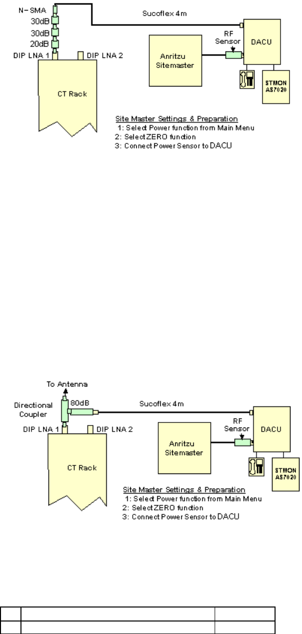
Printed Documentation
138
3. Calculate/determine total path loss and required DACU output power and hence
power meter reading.
4. Connect cables and equipment as per diagram below using 30+30+20dB calibrated
attenuators. If coupler calibration known set up as in step 9 and go to step 6
5. Zero power meter. Calibrate and apply measurement offset for operational frequency
if applicable.
6. On the AS4020 go to Top Menu >Setup Menu >RF Menu>RX Sensitivity. Set RX to
2500
7. Put AS4020 Shelf into test mode Off and then into test mode 3. (from AS4020 menu
select Setup Menu/RF Menu/RF Commissioning)
8. Configure the DACU using AS7020STMON according to modem shelf properties to
the correct frequency, PN code and ID number prior to entering test mode. If the
frequency can be entered using STMON then the FP command in the step 12 is not
necessary). If coupler calibration known go to step 11. The commissioning procedure
described in this document is not restricted to any particular RF channel or PN code.
However the user should make sure that both the CT and ST are programmed with
identical RF channel and PN code.
9. Using the values of the calibrated attenuators and cable calculate the loss of the
attenuators and cable between the DACU and CT as per diagram above: Note the
power meter reading.
10. Replace the calibrated attenuators with the coupler and note the power meter
reading. If the power meter is more than the previous one then the difference should
be added to the sum of the attenuator values and of less it is subtracted from the sum
of the attenuator values. This new value represents the attenuation of the coupler.
Attach a label with loss value to the coupler.
a Sum of calibrated attenuator losses
b Power meter reading with calibrated
Setup and Test
139
attenuators
c Power meter reading with coupler
d Difference between readings
e Coupler loss
if [c] is greater than [b] then subtract
[d] from [a]
if [c] is less than [b] then add [d] to [a]
Table 2
11. Populate the table below with values obtained from calibrated components and
planned levels to calculate/determine overall path loss and required ST output power
and hence required power meter reading.
RF Channel
No:
Cable Loss(1)
Coupler loss loss.(2)
RF Section
Loss Antenna-
CT( DACU RF Module).(3)
Sub Total (4) = 1+2+3
Required CT RX Level (5) See table 1 above.
DACU RF Power (6)=4+5
RF Section Loss Antenna - Power Meter (7)
Power Meter (8) = 6-7
Table 3
12. Make the test ST transmit by sending the following LAT commands from a terminal
emulator connected to the DACU
TE<space> 0<space> 4<space> 59 (this code sets the uplink modulation rate for the
ST for other required modulations replace the 59 with the session ids shown in table
1 above and should be set to the maximum modulation rate required)
FP <space>channel number (in decimal)
W<space> 0400003C
13. The terminal emulator should receive 0000000B for the uplink if the ST has acquired
a link.
14. On the AS4020 top panel go to Top Menu >Setup Menu >RF Menu>RX Sensitivity
15. Set RX gain by increasing/decreasing the value of RX sensitivity to achieve required
ST o/p level calculated as ( 8) in the table above for the required RX Level measured
on the power meter.
16. Record the value set in the test results
Link check
1. Enable the equalizer by typing the following LAT commands
ADE 1 10 (this enables the downlink channel equalizer and it should converge within
10 seconds)
ADS (this command displays the equalizer stats).
When the equalizer is adapting the stat reports Enabled = 1 Converged = 0
When the equalizer is adapting the stat reports Enabled = 0 Converged = 1 (the 0 for
Printed Documentation
140
enabled does not mean that the equalizer is disabled but that the training of the
equaliser is finished.)
Check that the equalizer converges OK.
2. From the ST LAT type TE1 to exit commissioning mode
3. From the AS4020 front panel exit commissioning mode by selecting RF
Commissioning = Off.
Setup and Test
141
Connecting the DACU
The following cables are provided with the DACU.
Airspan DACU Kitting List
Description Qty Comment
DC Power
Cord 1 Connects the dc power supply from the red and black 4mm sockets
on the DACU, labelled “+” and “-“ to either the IDU dc power jack,
labelled “12V ---- 1.5A”, or an external IDU dc power jack
AC Supply
Cable 1 Supplies mains to the C7 style (figure of 8) mains input on the main
DACU chassis, labelled “AC”
PC Laptop
Cable 1 Connects the 15-way D-Type socket on the IDU, labelled
“MAINTENANCE”, to the 9-way serial port socket on a PC or laptop
IF Link Cable 1 Connects the IF socket on the IDU, labelled with an antenna symbol,
to the IF socket on the RF Module, labelled “IF”
Hexagonal
Key Used to remove/replace the battery cover or RF Module from the
main DACU chassis
Laminated
Kitting /
Connection
sheet
1 A sheet showing a labelled photograph of all the DACU Kit items,
underneath which there is diagram showing how all the interfaces
are connected up.
Connect the cables as shown in the illustration below
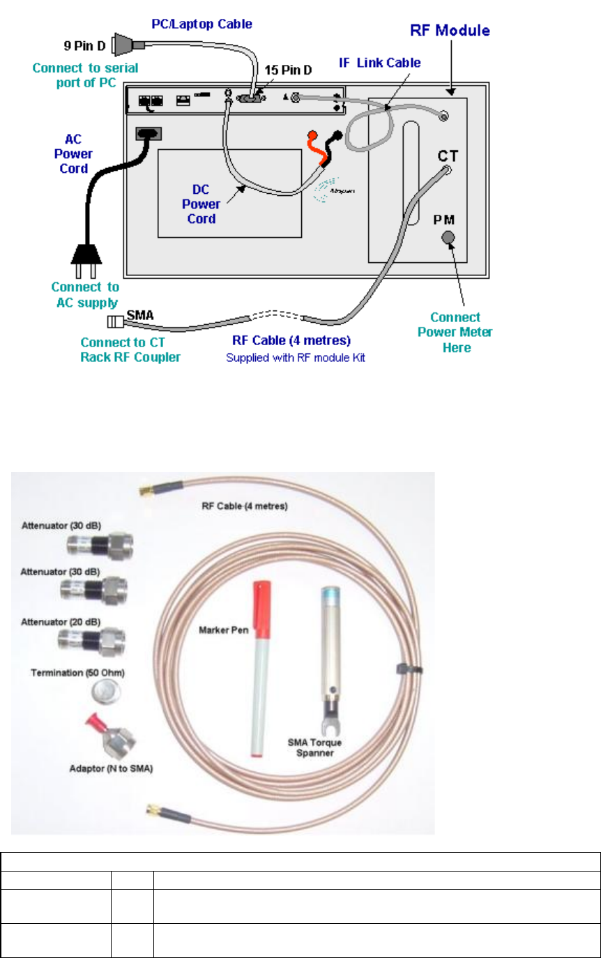
Printed Documentation
142
Fit the RF Module
The RF module is inserted into the compartment on the right of the DACU. it is secured using
two hexagonal headed screws.
Airspan RF Module Kitting List
Description Qty Comment
RF Cable (4
metres) 1 Connects the coupler on the CT rack to the SMA socket on the RF
Module, labelled “CT”
Attenuator
(20dB), 5W 1 Direct to combiner (first in line)

Setup and Test
143
Attenuator
(30dB), 5W 2 Second and third in line from combiner
Adaptor (N to
SMA) 1 Needed to connect N-type pads to 4m cable
SMA Torque
spanner 1 To tighten SMA's
Termination
(50 Ohm) 1 Terminates an unused power meter port
Laminated
Kitting /
Calibration
sheet (front)
1 A sheet showing a labelled photograph of all the RF Module Kit
items, underneath which there is a table to fill out all the calibration
details.
Laminated
Pro-forma
worksheet (on
reverse of
above)
1 To calculate overall insertion losses between CT and DACU RF
Module
Marker Pen 1 To fill in calibration details on laminates

Printed Documentation
144
Set RX Sensitivity without a DACU
Tools and equipment needed.
Item Description Recommended Model Quantity
1 Digital Multimeter Fluke 77 1
2 ST Test Unit, SIU with Modified Antenna at
appropriate band 1
3 30dB Attenuators;
5W Mini Circuits: BN-N30W5 2
4 30dB Attenuators;
2W M/A-COM:2082 6044 30:2W 2
5 Two Way Power
Divider Mini Circuits: ZAPD-4-S 1
6 50 ohm Termination
10W Arra N9510 1
7 Adaptor; N-SMA Huber & Suhner 33N-SMA-50-1 1
8 Adaptor; N-SMA Huber & Suhner 31N-SMA-50-1 1
9 Huber & Suhner Sucoflex 104; 0.5m 2
10
Co-ax Cables
Huber & Suhner Sucoflex 104; 4.0m 1
11 Cable SMA-MCX Huber & Suhner 30-05918-10 1
12 RF Power Meter Marconi 6970 1
13 Power Sensor Marconi/RFI 6970&5 6932/900 1
RX Sensitivity (Test 6)
The RX sensitivity is set according to the required CT RX level. It is important to note that the
lower the modulation rate the further the geographical spread. For maximum range the
AS4020 should use QPSK 1/2. Higher data rates may be achieved using higher orders of
modulation but the range will lessen as the modulation rate increase. This level is determined
as part of the planning function and takes into consideration the highest modulation rate to be
offered and the noise floor predicted in the planning stage.
The RX Level is set dependant on the highest operational modulation rate as follows. By
undertaking an appropriate level of RF planning the level is optimised in order to balance
uplink data rate and system range.
Typical levels are shown below for two network configuration scenarios:
For networks where only a single RF Channel is operating, or only adjacent + one RF
Channels are used (no co or adjacent channel interference), the following CT Rx levels apply:
Rx Level (dBm / RW)
Modulation
Code Rate
Below 3GHz
Above
3GHz
Session
ids for
LAT TE
command
in Mode 3
QPSK 1/2 -105 dBm -103dBm 58 or 59
QPSK 3/4 -103 dBm -101dBm 56 or 57
16QAM 1/2 -97 dBm -95dBm 54 or 55
16QAM 3/4 -93 dBm (see note 1) -91dBm 52 or 53
64QAM 3/4 Not supported on the uplink
Table 1
Note 1: Note, 16QAM ¾ is only supported on the uplink with up to 7RW Codes Active.
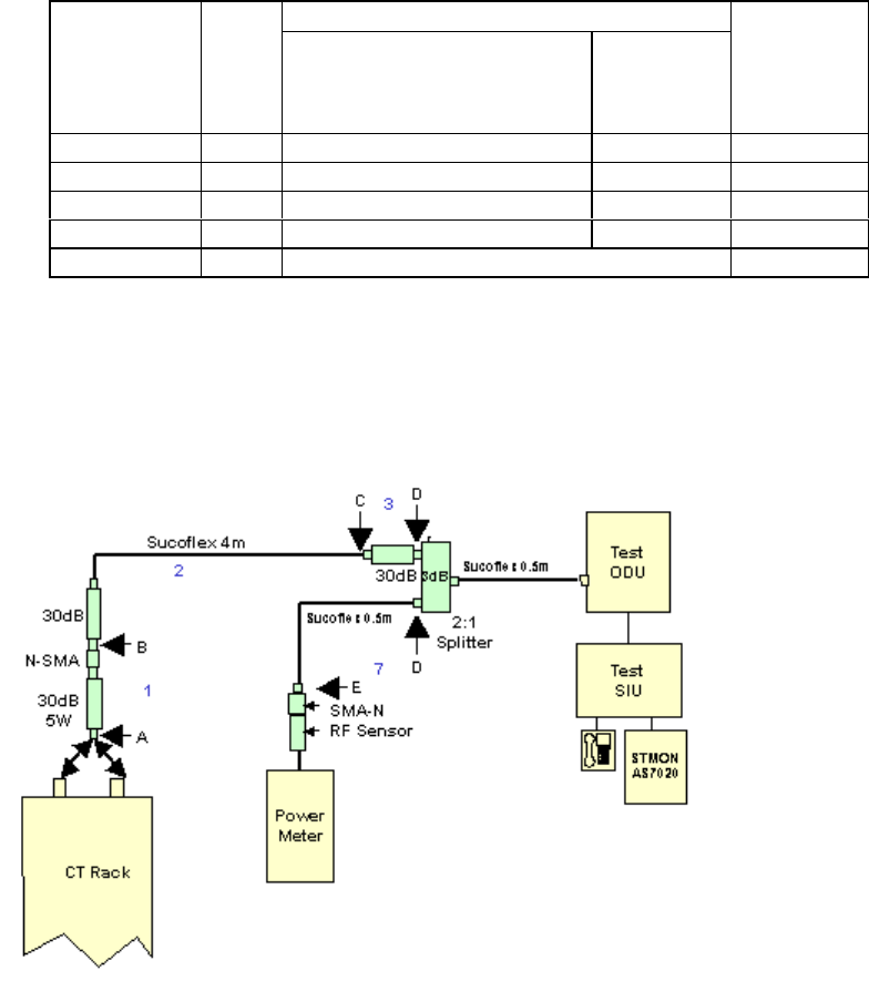
Setup and Test
145
For networks where co or adjacent frequencies are reused to provide cellular type
network coverage with limited available spectrum (ie. A relatively high level of co and
adjacent channel interference), the following CT Rx levels apply:
Rx Level (dBm / RW) Modulation
Code Rate
Below 3GHz
Above
3GHz
Session
ids for
LAT TE
command
in Mode 3
QPSK 1/2 -103 dBm -100dBm 58 or 59
QPSK 3/4 -101 dBm -98dBm 56 or 57
16QAM 1/2 -94 dBm -92dBm 54 or 55
16QAM 3/4 -90 dBm (see note 1) -88dBm 52 or 53
64QAM 3/4 Not supported on the uplink
Table 1a
1. To set the receive sensitivity, first set up a test network for the band under test as
shown below. The figure below shows a typical test setup with test equipment
connected directly to the outputs of the DIP/LNA and DIP/LNA2 as would be the case
for systems without a RF coupler.
Test Set-up
2. Zero power meter. Calibrate and apply measurement offset for operational frequency
if applicable.
3. On the AS4020 go to Top Menu >Setup Menu >RF Menu>RX Sensitivity. Set RX to
2500
4. Put AS4020 Shelf into test mode Off and then into test mode 3. (from AS4020 menu
select Setup Menu/RF Menu/RF Commissioning)
5. Configure the Test SIU using AS7020STMON according to modem shelf properties to
the correct frequency, PN code and ID number prior to entering test mode. The
commissioning procedure described in this document is not restricted to any
particular RF channel or PN code. However the user should make sure that both the
CT and ST are programmed with identical RF channel and PN code. If the frequency
can be entered using STMON then the FP command in the step 12 is not necessary)
6. Measure and calibrate the loss of all components shown in the diagram above. To
measure the losses of components use the TX output as a reference source.
Measure the TX output and place figure in table below.. Connect each component in

Printed Documentation
146
turn between the TX output and the power meter and measure the loss added as the
component is inserted. Measure (1)A-B, (2)B-C, (3)C-D and (7)D-E.
7. Calculate and enter values in calibration chart for the relevant frequency.
RF Channel No:
Ref TX output
A-B Atten.(1)
B-C Atten.(2)
RF Section
C-D Atten.(3)
Sub Total (4) 1+2+3
Required CT RX Level (5)
see table 1
ST TX Power (6)=4+5
RF Section D-E Atten (7)
Power Meter (8) = 6-7
8. Calculate/determine overall path loss and required ST output power and hence
required power meter reading.
9. Connect cables as per diagram above. Try to ensure that the network is set to reduce
the amount of radiated pick up. To ensure that it is the receive path that is being
measured and not pickup place an attenuator (6dB) into the network and check that
the meter falls by a corresponding amount. If it fails to do so additional screening of
the test network is probably required.
10. Connect a terminal emulator to the ST.
11. Make the test ST transmit by sending the following LAT commands from a terminal
emulator connected to the ST
TE<space> 0<space> 4<space> 59 (this code sets the uplink modulation rate for the
ST see table 1)
FP <space>channel number (in decimal)
W<space> 0400003C
12. The terminal emulator should receive 0000000B for the uplink if the ST has acquired
a link.
13. On the AS4020 go to Top Menu >Setup Menu >RF Menu>RX Sensitivity
14. Set RX gain by increasing/decreasing the value of RX sensitivity to achieve required
ST o/p level as calculated in step 8 for the required RX Level.
15. Record ST o/p level and value set.
Link Check
9. When the link has successfully acquired enable the equalizer by typing the following
LAT commands
ADE 1 10 (this enables the downlink channel equalizer and it should converge within
10 seconds)
ADS (this command displays the equalizer stats).
When the equalizer is adapting the stat reports Enabled = 1 Converged = 0
When the equalizer is adapting the stat reports Enabled = 0 Converged = 1(release
7.2x) or Enabled = 1 Converged = 1(release 7.3x)
Check that the equalizer converges OK.
10. From the ST LAT type TE1 to exit commissioning mode
Setup and Test
147
11. From the AS4020 front panel exit commissioning mode by selecting RF
Commissioning = Off.

Printed Documentation
148
Packet System Testing
Data Tests
To pass Ethernet traffic through the AS4020 system, it will be necessary to transfer data
between a Server connected to the “Traffic” Ethernet port of the AS4020 CT, and a PC
connected to an ST. To test basic functionality, the following throughput speed tests are
performed.
Test Method & Results:
Windows 2000 has a built-in FTP server. This is simple to use, free, and readily available,
therefore ideal for setting up a test system to measure AS4020 performance. However this
must be installed and activated before use. Also, some suitable test files must be added to
the FTP “home directory”, appropriately sized for transferring through the AS4020 system.
The FTP command-line client program (also included with Windows 2000) can be used for
the transfers.
The following tests assume that the FTP server has been set up, test files are available, and
that the method of measuring download speed used is as described in Annex A. The
modulation scheme in use can be found in the “ST Packet Line Classes” section of the
“Global Setup” tree, on the left hand side of the main NetSpan window.
The downloads can be automated into a batch file for ease of use – this way the test can be
run simply by double-clicking on the batch file, which is more convenient than downloading
“by hand”.
Equipment Required
2 PC’s with NIC cards enabled.
FTP Software (Windows FTP or use DOS prompt)
Windows 2000 Server Software
Access to the CT over the radio interface from a ST
Setting up FTP Server PC
1. Open the Control Panel (Start -> Settings -> Control Panel);
2. Open the “Add/Remove Programs” tool;
3. Click on the “Add/Remove Windows Components” button, found on the left side of the
window;
4. Select “Internet Information Services (IIS)” and click on the “Details” button;
5. Make sure that the tick boxes are selected for the following subcomponents :
“Common Files”, “File Transfer Protocol (FTP) Server” and “Internet Information
Services Snap-In”. It is not necessary to install (or uninstall) any other
subcomponents, as they are independent from the FTP Server;
6. Click “OK” on this dialog box, and then click on the “Next >” button. Installation will
start, and may take a few minutes to complete.
Note: The Installer program will probably need to copy some files from a Windows 2000
Installation CD. If you do not have a CD, it is possible that the installation files will have been
previously copied to the hard drive of the PC. If this is the case, search the hard drive for a
directory called “i386” and Browse to this directory when prompted for a CD by the installer
wizard.If necessary fit NIC card to PC.

Setup and Test
149
Configuration of the FTP Server:
The FTP Server needs a home directory – this is where the “root” of the FTP server will be
located, and where the files will be downloaded from. These steps detail configuring the
directory location, and additionally some other required parameters such as access rights:
1. Right-Click on the “My Computer” icon on the desktop, and choose the option “Manage”.
Note: It is possible that the icon will have been renamed, but is usually the blue computer icon
positioned at the top-left of the desktop.
2. In the “Computer Management” window that will appear, on the left side is a tree view.
Near the bottom of the tree view, expand the “Services and Applications” branch.
3. Under the “Services and Applications” branch, expand the “Internet Information Services”
branch.
4. Right-click on the “Default FTP Site” icon that will appear, and choose the “Properties”
option.
5. Working through all of the options, set up the FTP site as follows. Note, not all available
options are described here - where an option isn’t described below, it is not relevant to this
configuration. If you change an option as a result of following this table, you may want to
make a note of it so that the PC can be returned to the original settings when you have
finished testing:
FTP Site Tab:
IP Address (All Unassigned)
TCP Port 21
Connection Limited
to: 10
Connection Timeout 900
Enable Logging Disabled. Do not tick the
box.
Security Accounts Tab:
Allow Anonymous
Connections Enabled. Tick this box. Warning: Anonymous FTP access: The
above instructions will allow all computers to have Anonymous
read, and more importantly write, access to the directory used for
the root of the FTP Server. This is clearly not a desirable mode
in which to leave the PC when testing is completed. Airspan
recommends as a minimum to turn off “write” access, via the
“Home Directory” Tab.
Home Directory Tab:
A directory located
on this computer Select this option, as we will be downloading files from this PC.
Local Path The drive must be a local hard disk, and have 40Mbyte free
space (100Mbyte recommended). Make a note of the path, as it
is required in the next section. For convenience you may wish
to record it here:
Read / Write / Log
Visits Enable Read and Write, Disable Log Visits. Warning:
Anonymous FTP access: The above instructions will allow all
computers to have Anonymous read, and more importantly
write, access to the directory used for the root of the FTP
Server. This is clearly not a desirable mode in which to leave
the PC when testing is completed. Airspan recommends as a
minimum to turn off “write” access, via the “Home Directory”
Tab.

Printed Documentation
150
Creating suitable download / upload test files:
Due to the high transfer rates possible with the AS4020 system, suitably sized test files
should be transferred. The recommended test file sizes are of the order of 1Mbyte
(uploading) and 10Mbyte (downloading).
We must also ensure that any file compression does not result in files appearing to be
transferred faster than they actually are. The recommended method for performing the
transfer tests (described in the next section) uses an FTP method that transfers files in binary
mode, without compression. However, as other utilities may not do this, the test files should
not be compressible.
To assist with this, Airspan provides a utility for generating uncompressible files of varying
sizes. Inside the .zip file embedded below are two files – “filegen.exe” and “generate.bat”. If
you do not have an electronic copy of this document, you can request the embedded .zip file
by email. Send your request to support@airspan.com
Instructions:
1. Unzip the embedded .zip file. The files “filegen.exe” and “generate.bat” should be placed
into the FTP Site Directory that was recorded in the previous section.
Note: Use Windows Explorer to check that the files are in the correct location. Do not
use the “right-click” option to “Extract to folder …\FTP test file generation”, because a
new subdirectory will be created and the files placed there. You can use Windows
Explorer to move the files to the correct location if you have used this method to extract
the files, or have extracted them elsewhere on the hard disk.
2. Defragment the partition of the hard disk which contains the FTP Site Directory:
a. Opening Windows Explorer select the Drive letter containing the FTP Site Directory;
b. Right-Click on the drive letter and choose “Properties”;
c. Select the “Tools” Tab at the top;
d. Press the “Defragment Now…” Button;
e. When the defrag program opens, press the “Defragment” button.
Note: This may take many minutes to run, and may require some disk space to be
freed if there is less than 15% free disk space.
3. When the defragmentation is complete, navigate to the FTP Site Directory using Windows
Explorer.
4. Double-click on the “generate.bat” file.
Note: For information - The “filegen.exe” program takes the command line parameters
denoting the filename and size in Kbytes, and creates files containing random data (hence the
files cannot be compressed at all, they will grow in size if “zipped”). The “generate.bat” batch
file repeatedly calls the “filegen.exe” to create a set of uncompressable files of varying sizes.
You may wish to edit this file if you need different file sizes. The batch file will generate the
following files:
File Name File Size (Bytes)
100K 102,400
200K 204,800
500K 512,000
1M 1,048,576
2M 2,097,152
5M 5,242,880
10M 10,485,760
These numbers follow the binary data store convention of 1KB = 2^10 Bytes, 1MB = 2^20
Bytes.
The file generation process will take approximately 30 seconds to complete, depending on the
specification of the Server PC.
Setup and Test
151
Using the FTP Client, and automating the transfers:
To perform the data transfers, an FTP Client running on a PC connected to an ST will
download and upload data files to the FTP Server running on a computer connected to the
same network as the Traffic Port of the AS4020. To avoid the influence of other network
traffic, all other computers on the network should be disconnected. If this is not possible,
disconnect from the network, and connect the FTP Server directly to the Traffic Port of the
AS4020 using a crossed Ethernet cable.
The Traffic Port should be set to 100Mbit/sec, half-duplex mode. The FTP Server PC’s
Ethernet port should be set to “Auto Speed, Auto Duplex”, or alternatively to 100Mbit/sec,
half-duplex.
It is recommended to use the command-line FTP Client which is included with all versions of
windows, as this will already be available on the PC (as it is installed at the same time as the
TCP stack) and gives a speed result at the end of the transfer.
The FTP Server PC and the FTP Client PC must have IP addresses in the same subnet. If
the PCs can “ping” one another, then they will be able to perform FTP transfers between
them. Note that when measuring uplink speeds (i.e. in the direction from the ST to the
AS4020), it is not necessary to run an FTP Server on the ST. Instead the FTP Client on the
PC connected to the ST will perform an FTP upload to the Server.
Note: It is possible that an FTP download could be cancelled or aborted part way through (a
number of reasons could cause this). If this is the case, the partly transferred file will reside
on the hard disk, and will have the correct name but will not have the expected file size.
Therefore the file sizes should be checked before any transfers are made. The files can
easily be rebuilt simply by running the “generate.bat” batch file described in the previous
section. Alternatively, when transferring files, make sure to choose a different destination
filename – i.e. when downloading a file called “1M”, save it as “1M_downloaded”. This is
described in more detail below.
The following instructions for performing the transfers assume that the IP addresses of the
Client and Server PC are in the same subnet and can ping one another through the AS4020
system.
Create a working directory containing test files:
1. Create a working directory: Make a new directory on a hard drive with at least 40MB
free disk space. You can do this with Windows Explorer by selecting the hard drive
letter and choosing “File -> New -> Folder”. Rename the folder as appropriate (e.g.
“FTPtests”).
2. Copy the “Filegen.exe” and “generate.bat” files into this directory and run the
“generate.bat” batch file (this is described in greater detail in the previous section).
This will create a set of files which can be used for upload measurements.
3. Performing a manual file transfer: Open a command prompt window. This can be
achieved by following the menu “Start -> Programs -> Accessories -> Command
Prompt”, or by opening the “run” box (Press the “Windows” keyboard key and the
letter “R” simultaneously) and typing in “cmd” and pressing Enter.
4. Navigate to your working directory, for example if the new folder created in step 1
was “C:\FTPtests”, enter the following commands (all commands shown below should
have either the “Return” or the “Enter” key pressed after typing them):
c:
cd \FTPtests
The command prompt will show the directory in which you are working.
5. Run the FTP Client and instruct it to connect to the IP address of the FTP Server. For
example of your FTP Server IP address is 10.0.60.1, enter:
ftp 10.0.60.1
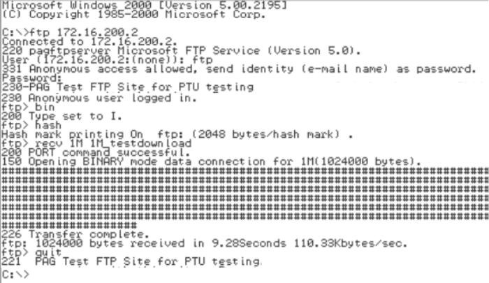
Printed Documentation
152
6. The Server will ask for a username and password. Enter the username “ftp”, and the
password can be anything, even left blank if the FTP Server is set up as described
earlier.
Note: A blank anonymous password will not work on all types of FTP server, some
may require a correctly formatted email address (e.g. a@b.com) as the password.
Also, the username ftp is equivalent to typing the username anonymous.
7. Switch the transfer mode to binary, by entering the command bin;
8. Turn on “hash marking”, by entering the command “hash”. This will print “#” symbols
across the screen when the transfer is in progress.
9. Transfer a file: The command to receive a file is “recv”, and to send is “send”.
Following the command you must enter the name of the file to transfer, and
optionally also the name to call the file when it has arrived.
For example, to send a file called “500K”, enter:
send 500K
And to receive a file called “2M”, and locally rename it to “2M_downloaded”, enter:
recv 2M 2M_downloaded
Note: Some FTP servers are case-sensitive, this is a common reason for a failed
download. Remember that Windows does not always display file names with their
names in the correct case. To see a list of files in the current directory of the FTP
Server, and their exact case sensitive names and file sizes, enter the command “ls –l”
(short for: list directory contents, using long format). You can use this command to
make sure the files you are intending to transfer are the correct length for the test you
wish to perform.
a. Wait for the transfer to complete. You will see “#” symbols scrolling across the
screen, at a rate proportional to the file transfer speed. You can cancel the transfer
by pressing CTRL + C, although the system will take a few seconds to take action
and close down the transfer.
When the transfer is complete, the session will show you the transferred speed. An
example transcript from Airspan’s Product Applications Laboratory is shown in the
screenshot below:
Note: As the FTP Client shows the speed at which the data in the file was
transferred, it will not show you the actual data throughput over the air interface. This
is because an allowance of 3.7% must be made to include the protocol headers
encapsulating the data. A description of these overheads and the 3.7% calculation is
shown in the technical note at the end of this section, along with details of other
overheads to consider. Referring to the transfer speed in the screenshot above, the
data transfer above resulted in an Ethernet frame throughput to the FTP Client of:
110.33KBytes/sec * 1.037 = 114.4KBytes/sec, or 915.3KBits/sec.
Setup and Test
153
Please refer to the technical note at the end of this section, explaining why the figure
will be less than the theoretical maximum data rate available.
10. To exit from the FTP program, type “quit” at the prompt
Creating batch files for automatic File Transfers:
As mentioned earlier, it will be much more convenient to have test batch files which will
automatically perform a file transfer, and then pause to show the results. The
command-line FTP program described above can be instructed to use a script file with
a set of commands, thus preventing the need to type them every time.
Included in the embedded .zip file below are sample files to perform a 10Mbyte
download, and a 1Mbyte upload. They are explained below, and if you use them you
will need to unzip them into your working FTP directory, and then edit them to use an
appropriate IP address for your FTP Server. The files are very small and easy to
create, if you do not have a paper copy of this document
The FTP program can be invoked using the syntax:
ftp –s:filename Where “filename” specifies a text file containing FTP commands; the
commands will automatically run after FTP starts.
The commands will be almost identical to those used in the “manual” method above,
the difference is the use of the “open” command to connect the FTP program to the
FTP server. A worked example (note text after the // are comments and must not be
included in the file):
Contents of “10MB_Download.bat”
ftp -s:10M_Download_Script.txt // invoke the FTP program using a script
pause // wait for a key press, so you can see the results
Contents of “10M_Download_Script.txt”
Open 10.0.60.1 // Server IP address: change this to match yours
ftp // Username for anonymous access
dummypassword@xyz.com // A password, in “email” format
bin // Change to Binary mode
hash // Turn on “hash marking”
recv 10M 10M_ downloadedfile // Get the file “10M” and rename it locally
quit // Exit the program
To automatically send a file, you will also need another batchfile to call the FTP
program with a different script file. The script file will be the same as the one above,
except the “recv 10M 10M_downloadedfile” command will be replaced with, e.g. “send
1M 1M_uploadedfile”.
Technical Note: An explanation of Ethernet, and Airspan protocol overheads in FTP
transfers:
The structure and relative sizes of the different portions of an Ethernet frame vary, but
a full sized FTP data transfer Ethernet Frame is 1514 Bytes, consisting typically of:
1. 14 Bytes Data Link Control (layer 2 of the OSI 7 Layer model):
Containing 6 bytes each of source & sestination MAC addresses, and 2
bytes Ethertype – in this case IP;
2. 20 Bytes Network Layer (layer 3 – in this case IP):Containing source
and destination IP addresses, and other information such as IP version,
Length, TTL, protocol, checksum, and several flags;
3. 20 Bytes Transport Layer (layer 4 – in this case TCP):Containing source
& destination Port numbers, sequence and ACK numbers, TCP Receive
Window size, User Data offset position, a checksum, and some flags;
4. 1460 Bytes Application Layer (layer 7 – in this case FTP) – the actual
file contents being transferred.

Printed Documentation
154
Therefore the “Ethernet” overhead is 100*1514/1460 = 3.7%
Additionally, there is an overhead associated with Airspan’s air interface. The data is
sent in small blocks, transmitted every 4ms on multiple RW channels simultaneously.
Additionally, an ST can receive up to 4 blocks simultaneously. Each block has a 4
byte overhead.
The number of bytes in a block depends on the modulation scheme being used, as per
the table below (showing the total bytes/block, including the 4 byte overhead):
Modulation
Total Bytes/Block
QPSK ½ 64
QPSK ¾ 96
16QAM½ 128
16QAM¾ 192
64QAM ¾ 288
As the Ethernet frame size is unlikely to be an exact multiple of the useable
Bytes/Block, there will be an additional overhead, as the block containing the last
section of an Ethernet frame will have some unused bytes, not completely filled by the
end of the frame.
Adding the overheads together results in the target throughput figures quoted in the
test plan. These numbers have been chosen as realistic figures that should be
achieved under laboratory test conditions.
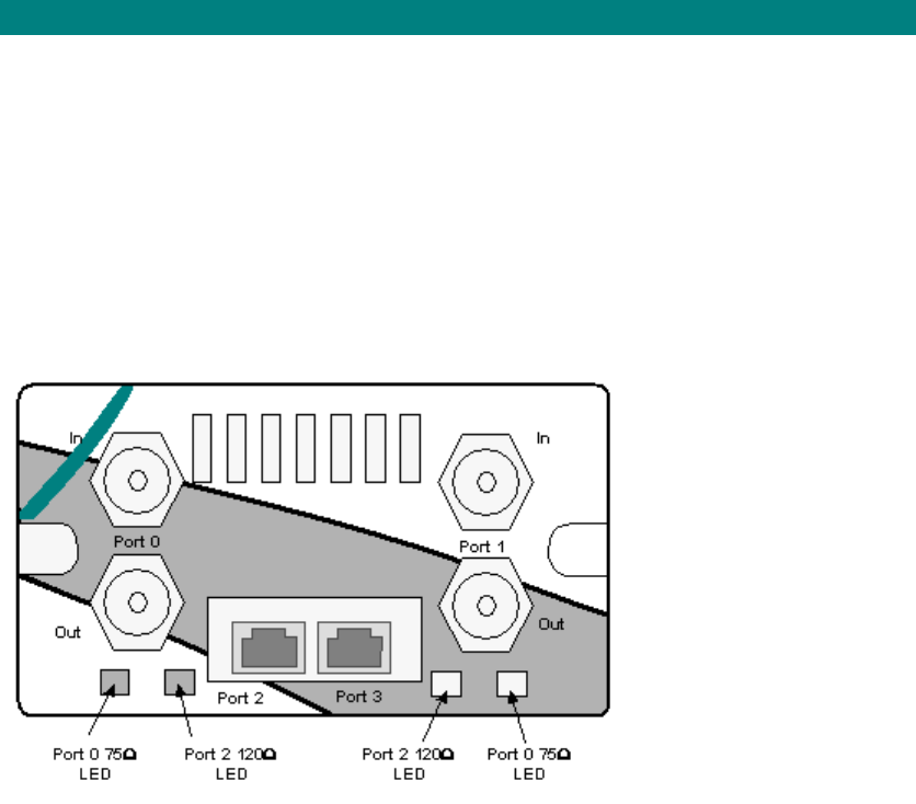
Setup and Test
155
Voice Option Testing
Option Module Test
It is only possible to fully test the voice module if the installation of the AC and the backhaul
connections to the switch are in place. Netspan also needs to be connected. The card is set
for 120ohm or 75ohm dependant on the type of backhaul selected on Netspan. When
connected to the AC using the correct impedance port the relevant LED should be green. A
red LED signifies link disconnection, and an amber LED signifies link present but faulty.
Check that the module responds to disconnection of a link. If a switch test is to be undertaken
the CT should be connected to a DACU and a voice call made from the DACU to the switch.

Printed Documentation
156
Central Terminal Rack Commissioning Test Results
Please photocopy test results sheet for use with each system
CUSTOMER:
SITE LOCATION:
RACK ID:
ENGINEER:
DATE:
Test Equipment Calibration
1.
Item
Description Model Serial No Calibration
Date
1 Digital Multimeter
2 RF Power Meter
3 Power Sensor
6 Test ST/DACU
7 60dB Variable
Attenuator
8 3dB Attenuator; 2W
9 30dB Attenuator; 1W
10 30dB Attenuator; 1W
11 30dB Attenuator; 2W
12 30dB Attenuators; 2W
DACU Calibration
Item
Description Output/loss Serial No Calibration
Date
1 DACU
2 RF Coupler Loss
3 RF Cable loss from
DACU to coupler

Setup and Test
157
Note: The cable supplied with each DACU is calibrated for a range of frequencies. If a cable
other than the original cable is used then an adjustment to the DACU output power to 98dB at
the receiver must be made. i.e. If the substitute cable has a 1dB less loss than the original
cable the output power for 98dB at the CT shown on the DACU needs to be reduced by 1dB
from the value shown on the DACU calibration label
Serial Number and Rev Level Record
Rack ID
Card Type Serial Number Rev Level
Combiner Shelf
RF DIP/LNA1
RF DIP/LNA2
RF Card 1
RF Card 2
RF Card 3
RF Card 4
PA1
PA2
MON1
MON2
PSU1
PSU2
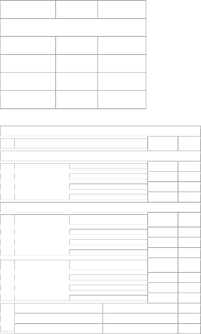
Printed Documentation
158
PSU3
Modem Shelves
AS4020 shelf 1
AS4020 shelf 2
AS4020 shelf 3
AS4020 shelf 4
Rack ID
TEST
# TEST LIMIT RESULT
Site Inspection & Verification
Modem Shelf 1
Modem Shelf 2
Modem Shelf 3
T1/E1Cabling
Modem Shelf 4
System Commissioning Tests
CT Rack Supply 1 -36.0 to -
60.0V DC
CT Rack Supply 1
Extn Rack Supply 1
Test
1a Exchange DC Voltage
Extn Rack Supply 2
CT Rack Supply 1 -36.0 to -
60.0V DC
CT Rack Supply 2
Extn Rack Supply 1
Test
1b Exchange DC Voltage
Expn Rack Supply 2
PSU 1 Output Voltage 13.5 VDC ; +/-500mV
PSU 2 Output Voltage 13.5 VDC ; +/-500mV
Test
2
PSU 3 Output Voltage 13.5 VDC ; +/-500mV
Setup and Test
159

Printed Documentation
160
AS4000- ACCESS CONCENTRATOR ACCEPTANCE FORM
CONTRACT OR CUSTOMER'S REF. NO:
AIRSPAN NETWORKS REF. NO:
SITE IDENTITY:
The Customer accepts that the following equipment has been supplied, installed and
tested.
Customer Representative
Name:__________________________
Position:________________________________
Date:___________________________
Signature:______________________________
Airspan Representative
Name:__________________________
Position:________________________________
Date:___________________________
Signature:______________________________
Airspan COPY
AS4000- ACCESS CONCENTRATOR ACCEPTANCE FORM
CONTRACT OR CUSTOMER'S REF. NO:
AIRSPAN NETWORKS REF. NO:
SITE IDENTITY:
The Customer accepts that the following equipment has been supplied, installed and
tested.

Setup and Test
161
Customer Representative
Name:__________________________
Position:________________________________
Date:___________________________
Signature:______________________________
Airspan Representative
Name:__________________________
Position:________________________________
Date:___________________________
Signature:______________________________
CUSTOMER COPY

163
General
Customer Material Repair and Return Procedures
Introduction
This document describes the procedures, responsibilities, and terms and conditions for
the repair and replacement services offered by Airspan Communications Limited (Airspan)
to its customers and approved contractors. It shall apply only to Field Replaceable Units
(FRUs) manufactured or supplied by Airspan Communications Limited.
For the purpose of this document, FRUs comprise those units and Printed Circuit Boards
(PCBs) normally replaceable at the site by disconnection/reconnection, but excluding
consumables and frame assemblies.
Where the contents of this document conflict with the contract of purchase, the
requirements of the contract of purchase shall govern.
Purpose of Document
The purpose of this document is to describe the actions that a customer needs to return a
suspect faulty unit is returned to Airspan for repair or replacement. It details what actions
need to be taken by Airspan and their Customers to ensure a clean flow of product.
Forms Required
The following forms are used when returning material for repair:
Return and Repair Tag
Defective Equipment Information Form
Responsibilities
Airspan is responsible for:
a. Informing the customer of any FRU that is not repairable due to misuse,
miscarriage or expiry of the warranty agreement.
b. Handling returns and replacements and performing all repair work to established
quality procedures.
c. Carrying out repair or replacement within the time-scales defined in this
document.
d. Ensure a sufficient rotapool stock is maintained to support FRUs for up to 10
years after they cease to be in production.
The customer is responsible for:
a. Ensuring that any FRU containing Electrostatic Sensitive Devices (ESDs) are
handled and packaged according to the requirements of specification BS
EN100015 or an equivalent standard applicable in the customer’s country.
b. Providing with the FRU the documentation detailed below.
c. Ensuring that the operating environment of any FRU has not exceeded the
manufacturer's recommended environmental specifications.
d. Ensuring that any electrical apparatus connected to a unit meets the necessary
BS EN 41003: 1993 specification or an equivalent standard applicable in the
customers country.
e. Ensuring that the manufacturer's installation and handling procedures have been
followed correctly.
General
Printed Documentation
164
The customer bears the risk associated with any FRU returned for repair or replacement
until Airspan receives the item. The customer bears the cost of delivery of the FRU for
repair
Airspan bears the risk associated with the return of a repaired FRU or replacement until
the customer has taken delivery of it. The title for any repaired or replaced unit passes to
the customer on delivery, providing that the appropriate payment has been made to
Airspan.
Airspan reserves the right to charge the customer the full repair charge or the full list price
of the FRU, as appropriate in the circumstances, if the customer has violated any
applicable standards and precautionary measures.
Airspan reserves the right to modify or update these repair and return procedures.
Definition of Warranty
In-Warranty
Airspan warrants that the Equipment it supplies will be free from defects in materials and
faulty workmanship and that the Software it licenses to the customer will conform in all
material respects to Airspan’s published specifications therefor for a period of twelve (12)
months from date of shipment by Airspan to the customer (the “Warranty Period”). In no
event will Airspan be obliged to provide on-site maintenance under its warranty. Airspan
shall, at its option, offer to repair or replace any itemFRU within the Warranty Period
without additional charge provided that:
a. Inspection by Airspan Goods In confirms that the returned item has been
packaged securely and according to all applicable standards, and that the item is
of a recognised build standard.
b. Inspection of the returned goods by Airspan indicates that the defect was not
caused by maintenance, repair, or alterations by other than Airspan or their
authorised agents, or by abuse or improper use.
c. Notice of the claimed defect is given in writing to Airspan within one (1) year after
delivery.
d. The necessary fault information detailed below is enclosed with the returned item.
If any of the conditions in sections a, b, and c above are not met, Airspan reserves the
right to charge the customer the full standard repair charge for that item.
Out-of-Warranty
Any FRU supplied or manufactured by Airspan shall be deemed to be out of warranty if a
period of more than twelve months from date of delivery to the customer has elapsed or:
a. Inspection by Airspan indicates that the returned item has not been packaged
securely and according to all applicable standards (in particular BS CECC-
00015:part1: 1991), or that the item has been changed and is not of a recognised
build standard.
b. Inspection of the returned goods by Airspan indicates that the defect was caused
by maintenance, repair, or alterations by other than Airspan or their authorised
agents, or by abuse or improper use.
c. Notice of the claimed defect was not given in writing to Airspan within one (1) year
after delivery.
Warranty Period on Repaired FRUs
Normal Repair In-warranty
The warranty period for an FRU repaired or replaced by Airspan under warranty shall be
ninety (90) days from the date of shipment by Airspan or until the end of its original
Warranty Period, whichever is the greater.

General
165
Normal Repair Out-of-warranty
a. The warranty period for a FRU repaired or replaced out of warranty shall be ninety
(90) days from the date of shipment of the item by Airspan to the customer.
Repair and Return Procedure
The normal process is for the customer to obtain a Return Material Authorisation (RMA)
number, and then return the suspect faulty item to Airspan for repair. Airspan will repair the
FRU, or replace it if appropriate, and return it to the customer. This RMA number should be
quoted on all subsequent correspondence concerning the item.
For an additional charge, and providing suitable alternative is available, Airspan will
provide an Advance Replacement.
Outline Flowchart of Material Return Process
The flowchart below outlines the various actions involved in the material return process.
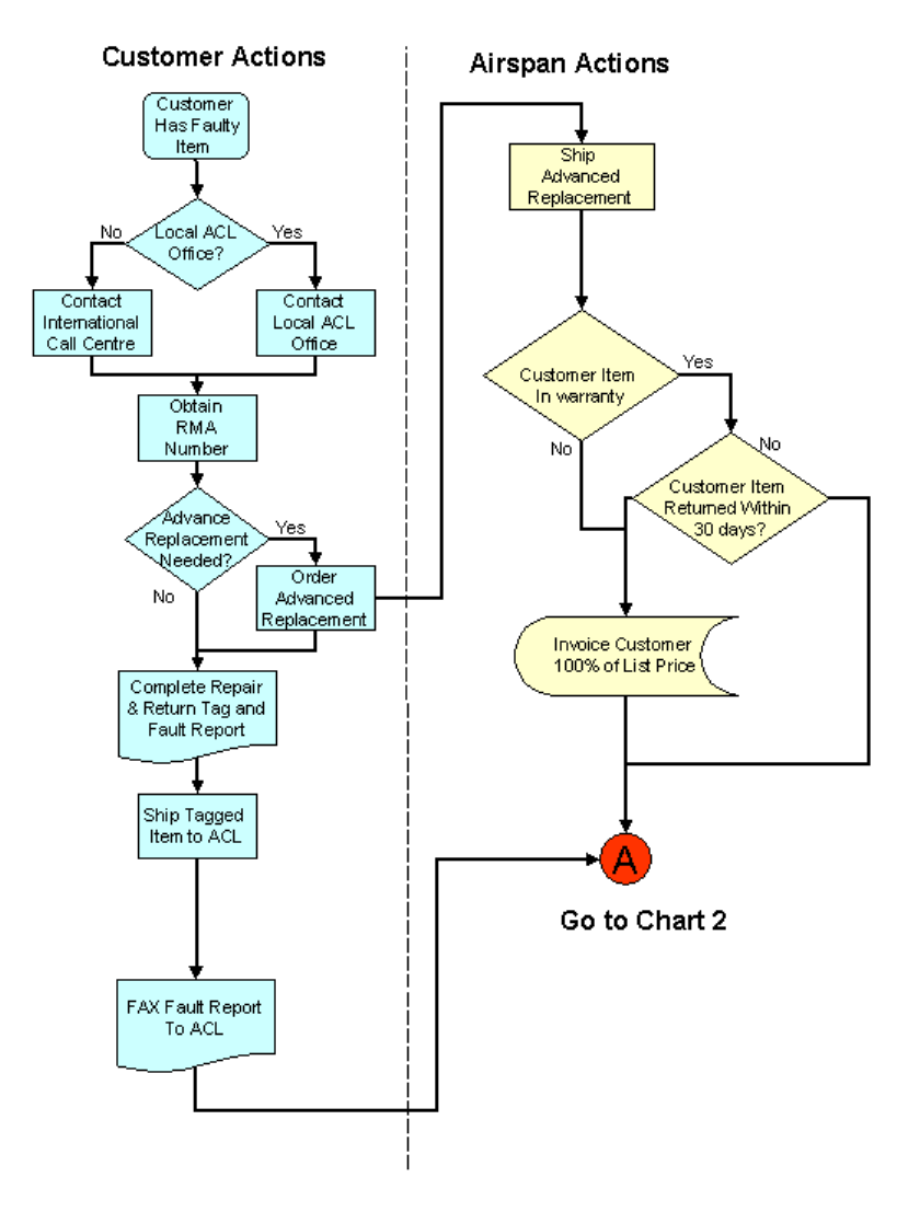
Printed Documentation
166
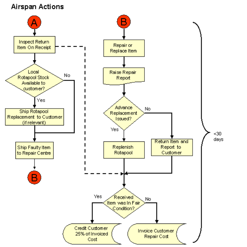
General
167
Action Taken by Customer Requesting a Repair Return
Whenever a customer has a query, or determines that they have a suspect faulty FRU
that they wish to return, they should take the following action:
a. Contact either the local Airspan office or the 24-hour Airspan International Call
Centre. The minimum information to be provided includes:
Company Name and Address
Contact Name and Telephone Number
Original Purchase Order No in the case of an in-Warranty return, or an authorised
Purchase Order Number for a non-warranty return
Description, part numbers, serial numbers and quantity of items to be returned
b. Airspan will fax to the customer an RMA No, which should be quoted on all
subsequent correspondence.
c. For each item, complete a Return and Repair Tag (Appendix 1) and attach it to the
item.
d. Return the item to Airspan in accordance with the shipping instructions.
e. If practicable, complete the Defective Equipment Information Form (Appendix 2) to
assist subsequent diagnosis and repair, and fax the completed form to Airspan.
Contact Addresses
The Call Centre operates 24-hours a day, and is contacted at:

Printed Documentation
168
Tel:+44 1895 467 467
During UK working hours, the Customer Service Help Desk can be contacted at:
Tel:+44 1895 467 239
Fax:+44 1895 467 472
Unless instructed otherwise, customers should ship the return item to the following
address: Customer Service
Airspan Communications Ltd
Airspan House
Cambridge House
Oxford Rd
Uxbridge
Middlesex
UB8 1UN
England
The local Airspan Account Team will provide details of any alternative local office contact
numbers and addresses.
Information to be Provided
The customer should provide the following information as a minimum with each item
returned:
RMA No.
Customer Name, Address, and contact person.
Description of Item.
Part No of Item.
Serial No of Item.
Fault Description.
This information can be placed on the Return and Repair Tag , which is attached to the
item being returned. Failure to provide this information could result in delays in the return
of the repaired items.
The customer is encouraged to complete and return the Defective Equipment
Information Form to provide more comprehensive information on the symptoms of the
reported fault. The more information that is provided concerning the nature of the
suspected fault, the better will Airspan be able to diagnose any fault and effect a repair.
Action Taken by Airspan
a. On receiving a request for a repair return, the Call Centre or Local Office will arrange
for the customer to be provided with an RMA number and shipping instructions.
b. On receipt of the item at the Uxbridge Repair Centre, Airspan will inspect it to confirm
that it has been packaged securely and according to all applicable standards, and
that it is of a recognised build standard.
c. Carry out fault diagnosis, confirming that any defect was not caused by maintenance,
repair, or alterations by other than Airspan or their authorised agents, or by abuse or
improper use.
d. Repair the FRU, or if it is beyond economic repair, replace it with an item of
equivalent fit, form and function.
e. Return the item to the customer with a brief report on the work carried out.
Replacement of FRUs
FRUs returned to the customer as replacements become the property of customer, and
the original item becomes the property of Airspan.
Replacements will be functionally equivalent to the original FRU and will be drawn from
Airspan’s Rotapool inventory.
Advance Replacement
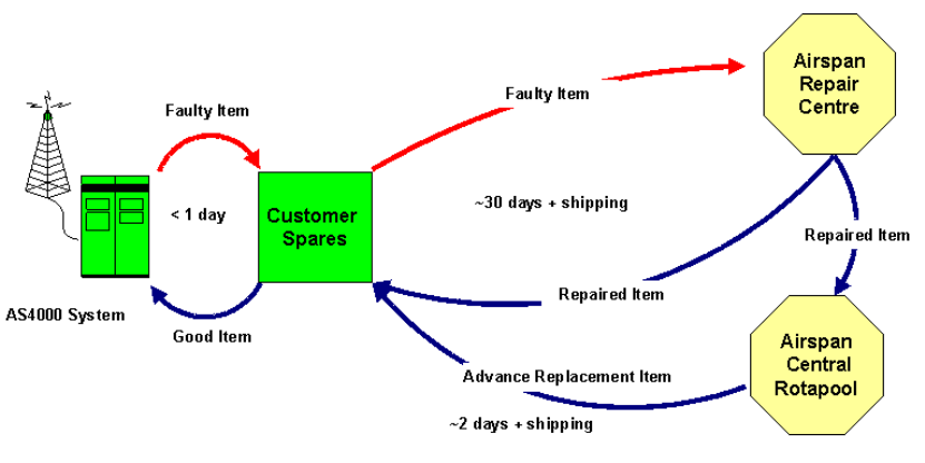
General
169
In-Warranty Advance Replacement
If a FRU is under warranty, and is critical to the customer’s system, Airspan will despatch
a suitable replacement, if available, from the rotapool in advance of receiving the suspect
item.
Airspan will ship the replacement item from the nearest location holding rotapool stock of
that item.
Out of Warranty Advance Replacement
If an FRU is no longer under warranty, as defined above, the customer may request an
advance replacement item. Airspan will issue a quotation to the customer for a
replacement.
Airspan will issue a quotation to the customer for a replacement. This service is additional
to the standard terms and conditions, and is wholly dependent on the availability of spares
at the time of request
Return FRU
The customer should ship the return FRU to Airspan within 30 days of receiving the
advance replacement, to avoid being charged the full cost of that advance replacement.
Service Turn Around Times
Airspan shall endeavour to repair and return FRUs, or replace them if appropriate, within
30 working days of receipt of the item from the customer.
Advance Replacements, if available, should be shipped within 2 days.
Rotapool Spares
For an additional charge, Airspan will maintain a Rotapool of critical FRUs for the
customer in region that can be used as a buffer stock to significantly reduce the
replenishment time for customer spares stocks.
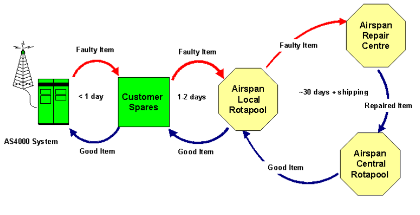
Printed Documentation
170
Repair Charges
In Warranty Charges
Providing the "in-warranty" conditions are met, Airspan will carry out all repairs or
replacements free of charge.
Out of Warranty Charges
For FRUs that are out of warranty, repairs shall be carried out at the standard rate for that
item, as listed in the Repair Price Schedule.
Airspan will provide prices on application for FRUs not listed in the Repair Price Schedule.
Beyond Economic Repair
Should a repair be uneconomical, Airspan reserves the right to replace the FRU with a
functional equivalent. Airspan will notify the customer accordingly and determine the
customer’s wishes regarding the disposition of the ‘non-repairable’ item.
For non-warranty repairs, Airspan may subsequently invoice the customer for return
shipping plus a handling charge.
No Fault Found
Should a returned FRU be found to have no defects, or only require the replacement of
consumable parts, the standard repair rate for that item shall be charged.
Consumable parts shall include, but are not limited to, fuses, bulbs, batteries, etc.
Advance Replacements
The standard charge for advance replacement of "in-warranty" FRUs is $200 per item.
If the return item is not received at Airspan within 30 days from the date of shipment of the
replacement , Airspan shall charge the customer the current list price of the replacement
unit.
For the advance replacement of "out-of-warranty" items, Airspan shall charge the
customer the current list price for the replacement FRU and credit 25% once the return
item is received.

General
171
Warranty on Repaired Items
Normal Repair In-warranty
The warranty for an item repaired or replaced in warranty shall be 90 days or the
remainder of the original outstanding warranty period for the returned item, whichever is
the greater.
Normal Repair Out-of-warranty
The warranty for an item repaired or replaced out of warranty shall be 90 days from
delivery of the item to the customer.
Return & Repair Tag
Airspan provides a tag to be attached to each item being returned. When completed, the tag
provides sufficient information for the item to be tracked throughout the repair and return
process.
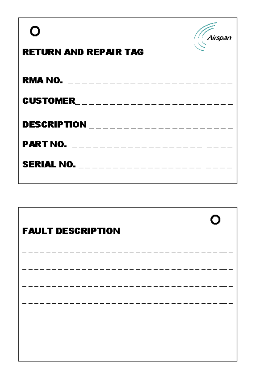
Printed Documentation
172

General
173
Defective Equipment Information Form
RMA Number (provided by Airspan)
Card/Assembly Description
Part Number and Revision (if Applicable)
Serial Number
Date Commissioned
Date Fault Reported
Location of Assembly in CT Rack Shelf
Location of Subscriber Terminal
SUBSCRIBER TERMINAL INFORMATION
Power Supply Type (e.g. I, II or IV)
RX AGC Voltage
TX PC Voltage
ST Programming Code
Description of Fault
Comm Port OK?
Line Voltage Line 1? Line 2?
CENTRAL TERMINAL INFORMATION
Card Type
Modem (Number)
TU
Analogue card
RF Card
Other (Specify Type)
Description of Fault
Sitespan Information
Packing and Shipment
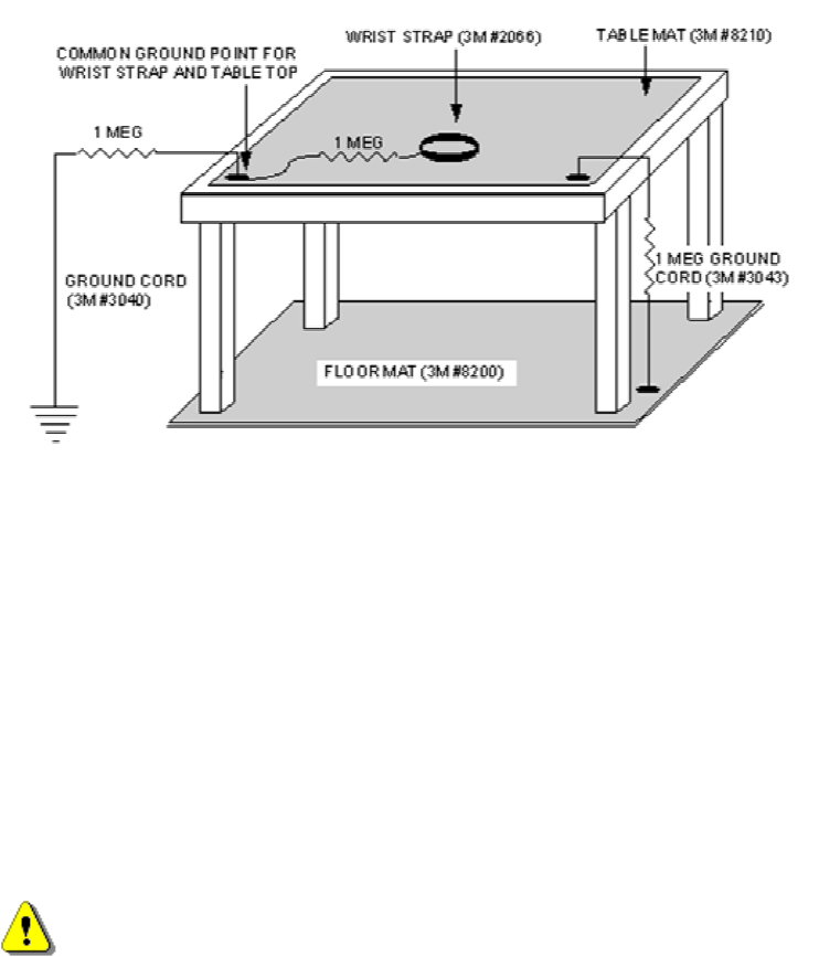
Printed Documentation
174
Circuit Board Assemblies
Circuit board assemblies must be individually boxed in Airspan-approved shipping
containers, to properly protect them from static electricity damage.
Static Control Rules
Airspan uses state-of-the-art semiconductors to obtain the fastest, most reliable operation.
These components are highly sensitive, and can be damaged by a static discharge as low
as 250V. Individuals may generate enough static to damage a component without noticing
the discharge, so must take precautions to control static.
Static Electricity Control
All sensitive Printed Circuit Boards (PCBs) must be handled at a static-safe work area.
The minimum requirement is a workbench with a grounded work surface, a grounded floor
mat, and a wrist strap. When a board is changed at the switch, a portable field service
grounding kit must be used.
Figure 1 shows the grounded workbench.
Figure 1. Printed Circuit Card Workstation
All boards must be transported in a static-shielding bag.
The following procedures reduce the possibility of static discharge damage:
a. Wearing a wrist strap while handling PCBs.
b. Attach the string of the Airspan Return and Repair Tag to the ejector/injector of the
PCB.
c. Insert PCBs into approved static shielding bags with repair tags remaining outside the
shielding bag. Do not insert repair tags into static shielding bags.
d. Pack/unpack PCBs at a static-safe workbench.
e. Transfer boards in a static-shielding bag or non-conductive board container.
f. Properly ground storage shelves.
g. Properly ground personal wrist straps while transferring boards to the storage
shelves.
Shipping Boxes
WARNING:;A box of boards must not contain other heavy items that could
cause part damage.
PCBs
General
175
Individually boxed PCBs must be placed into a larger packing case for shipment. Board
boxes alone do not sufficiently protect against shipping damage.
Empty space in shipping cases must be filled with additional shipping boxes to prevent
part movement and damage during handling.
Power Supplies And Peripherals
Each type of assembly must be shipped in its specifically-designed packing box. Retain
individual shipping containers for these items.
To prevent damage, all mechanical movable parts (such as disk heads and rotor) must be
in the locked/secure position before handling/shipping.
All handling must be done using only the handles and/or handholds so the equipment is
not damaged.
All items must be accompanied by a completed Airspan Return and Repair Tag.
Shipment To Airspan
The customer should ship the item to the Customer Service Centre at Uxbridge unless
Airspan has provided an alternative shipping address.
The cost of shipping returns to Airspan for repair shall be borne by the customer, and all
risks associated with the shipping remain the responsibility of the customer.
Items under repair, and their subsequent return to the customer shall be the responsibility
of Airspan.
Should the customer specify expedited shipping for the return of a repaired FRU or an
advance replacement, all costs incurred shall be borne by the customer.
Damaged Shipment
If a shipment is received with visible damage to the container, the receiving party should
document the damage and report it to the Airspan Customer Service Centre.
If concealed damage is found after the shipment is accepted, , the receiving party should
document the damage and report it to the Airspan Customer Service Centre. Airspan will
arrange for the freight company to inspect the damaged shipment and file an inspection
report so that a claim can be initiated.

Printed Documentation
176
Specifications
Central Terminal
The following tables provide technical specifications for the Central
Terminal.
PHYSICAL CHARACTERISTICS
CT Rack Dimensions, (without
brackets): Full Height
Compact
Width 600mm 600mm
Height 2175mm 1500mm
Depth 300mm 300mm
Shipping Weight:
Rack Frame 60 kg
Air Inlets/Outlets 16.5 kg
Combiner Shelf 30 kg
Power Amp 4.5 kg (each)
LNA 1 kg Frequency Dependant
TX filter 1 kg Frequency Dependant
PSU 1.5 kg (each)
AS4020 Shelf 3.5kg (each)
ENVIRONMENTAL
Minimum Maximum
Operating Temperature -5 C +45 C
Relative Humidity, non-condensing 0% 95%
Storage Temperature -40 C 85 C

General
177
Storage Humidity, non-condensing Less than 100%
Air Pressure 70 kPa 106 kPa
POWER REQUIREMENTS
DC Input Voltage Operating Range. (N.B.
This supply to be a guaranteed SELV from an
EN60950 approved source.)
Maximum Range, -36.0V DC to -
60.0V DC @ 540W
DC Input Current (Fully populated CT Rack) 11.5 Amps max. @ -48V DC
9 Amps max. @ -60V DC
Recommended Power Distribution Fusing
(With a readily accessible disconnect device
which will isolate all poles.)
-36.0V DC to -60V DC 30Amps
High Inrush
Power Distribution CT Fusing --36.0V DC to -60V DC 30Amps
each feed
Warning. The maximum DC input should not exceed 60 Volts. Voltages in excess of this are
considered hazardous.

Printed Documentation
178
Copyright Information
1. Airspan Networks Inc 2003
2. This manual is subject to revision.
3. All rights reserved.
4. Right of modification reserved.
5. This manual is supplied without liability for errors or omissions.
6. No part of this manual may be reproduced or used except as authorised by contract
or other written permission.
7. This equipment is conditioned by the requirement that no modifications are made to
the equipment unless the changes or modifications are expressly approved by the
Airspan Communications Corporation
8. Prerequisite skills: Personnel installing, commissioning, and maintaining the Airspan
products must have a basic knowledge of telephony and radio communications, and
have experience in installing, commissioning and maintaining telecommunications
products. Airspan provides a range of comprehensive training courses specifically
aimed at providing operators/users of Airspan products with the prerequisite skills to
install, commission and or maintain the product. The courses are tailored to provide
the level of training required by the operator/user.
9. AS4020 and AS8200 are brands of Airspan Networks Inc

General
179
Contact Information
UK Office for sales and general enquiries
Airspan Communications Ltd
Cambridge House
Oxford Road
Uxbridge
Middlesex
UB8 1UN
Call +44 (0) 1895 467100
Fax +44 (0) 1895 467101
email sales@ airspan.com
Internet: Airspan.com
Customer Service Help-Desk for customer service emergency
Airspan Communications Limited
Cambridge House
Oxford Road
Uxbridge
Middlesex
UB8 1UN
Int. Tel: +44 (0) 1895 467 467
Int. Fax: +44 (0) 1895 467 472
E-mail: Support@Airspan.com

Printed Documentation
180
Problems with this Guide
If you encounter any problems or difficulty using this guide. Please Contact:
Malcolm Windett
The Documentation Manager
Airspan Communications Ltd
Cambridge House
Oxford Road
Uxbridge
Middlesex
UB8 1UN
Call +44 (0) 1895 467185
Fax +44 (0) 1895 467182
email mwindett@ airspan.com

General
181
Document Purpose
General Purpose of Document
This document describes the installation and commissioning of the Airspan AS4020
Central Terminal (CT) Racks and associated shelves to Release 7.21 specifications.
Prerequisite skills
Personnel installing and commissioning Airspan products must have a basic knowledge of
telephony and radio communications, and have experience in installing
telecommunications products. Airspan Networks provides a range of comprehensive
training courses specifically aimed at providing operators/users of AS4020 products with
the prerequisite skills to install, commission and or maintain the product. The courses can
be tailored to provide the level of training required by the operator/user.
This manual is intended for use by persons familiar with the AS4000/AS4020 product
having attended the Airspan Central Terminal Installation and Commissioning training
course prior to performing the procedures in this practice.
Installation Tasks
The installation procedures are arranged as a series of tasks and are generalised to cover
the majority of applications and configurations. If your particular system application is not
covered, call Airspan for assistance at the following number: Call +44 (0) 1895 467100
Printed Documentation
182
Warnings and Cautions
SAFETY
1. Read and follow all warning notices and instructions marked on the product or
included in this manual
2. Do not allow anything to rest on the power cord and do not locate the product where
persons could step or walk on the power cord.
3. When installed in the final configuration, the product must comply with the applicable
Safety Standards and regulatory requirements of the country in which it is installed. If
necessary, consult with the appropriate regulatory agencies and inspection
authorities to ensure compliance.
4. No hazardous RF radiation is emitted from the equipment.
WARNING - HAZARDOUS VOLTAGES
1. On AC installations, hazardous voltages exist. Use caution when verifying or working
with AC power. Remove metal jewellery that could come into contact with AC power.
2. On DC sections, short circuiting the low voltage, low impedance circuits can cause
severe arcing that may result in burns or eye damage. Remove rings, watches etc. to
avoid shorting DC circuits.
The CE Marking on an Airspan product signifies that it has been certified according to the
EMC directive 89/336/EECand the low voltage directive 73123/EEC or the Radio &
Telecommunications Terminal Equipment Directive 1999/5/EC . The product fulfills the
requirements according to the following standards:
EN300385 for EMC
including.
EN55022 Group 1 Class A for the Central Terminal Emissions.
EN55022 Group 1 Class B for the Subscriber Terminal Emissions.
EN60950 Safety
NOTES
1. The Subscriber Terminal equipment has been tested and found to comply with the
limits for a Class B digital device, pursuant to part 15 of the FCC Rules.
2. Airspan products do not contain hazardous substances (as defined in UK ‘Control of
Substances Hazardous to Health Regulations 1989’, and the ‘Dangerous Substances
Regulations 1990’). At the end of any Airspan product’s life cycle, the customer
should consult with Airspan to ensure that the product is disposed of in conformance
with the relevant regulatory requirements
3. Airspan products do not contain hazardous substances (as defined in UK ‘Control of
Substances Hazardous to Health Regulations 1989’, and the ‘Dangerous Substances
Regulations 1990’). At the end of any Airspan product’s life cycle, the customer
should consult with Airspan to ensure that the product is disposed of in conformance
with the relevant regulatory requirements
CAUTION: any modifications to this device not expressly authorised by the
manufacturer could void the user's authority to operate this device.
The following products are FCC compliant:
AS4000 Central Terminal
AS4000 Access

General
183
Concentrator
AS4000 R series SIU
Responsible party for compliance is:
Charles Blackham, Airspan Networks Inc.,Cambridge House, Oxford Rd, Uxbridge,
Middlesex, England, UB8 1UN. Telephone (44) 1 895 467450.
CAUTION: European Directive 1999/519/EC details basic restrictions and reference
levels on human exposure to electromagnetic fields as advised by the ICNIRP. The directive
states that adherence to these recommended restrictions and reference levels should provide
a high level of protection as regards the established health effects that may result from
exposure to such fields.
By the very nature of the system design and installation users will not find them selves within
close proximity of the Central Terminals Antenna.
Standards EN50383 and EN50385 are the applicable harmonised standards for EM fields
generated by fixed wireless equipment.
The Electromagnetic fields generated by the Central Terminal antenna are below the
recommended safe levels at all distances greater than 65 cm from an approved Airspan
antenna.
The safe distance from a non-approved antenna of length D and Sector Angle δ may be
calculated using the formula:
Safe distance, r = 36 / (π * D * δ)
If in doubt, please contact airspan_compliance@airspan.com

Printed Documentation
184
Issue Status
Issue Date Notes
Rev A December-2002 Release 7.10
Rev B July 2003 Release 7.11
Rev C September-2003 Release 7.20
Rev D September-2003 Release 7.20 changes to DACU.
Rev E October 2003 Release 7.21
Rev F January 2004 Release 7.22
Rev G January 2004 Release 7.22 Updated AS4020
test

185
Glossary
A
A/D: Analogue/Digital
AC: Access Concentrator
ADPCM: Adaptive Differential Pulse Code Modulation
AGC: Automatic Gain Control
AIS: Alarm Indication Signal or All Ones
AMI: Alternate Mark Inversion
AU: Analogue Unit
B
BER: BIT Error Rate
C
CAS: Channel Associated Signalling
CPE: Customer Premises Equipment
CT: Central Terminal
CTU: Concentrated Tributary Unit
CU: Compression Unit
D
D/A: Digital/Analogue
DA: Demand Assignment
DACU: Demand Assignment Commissioning Unit
DC: Direct Current
DIP: Diplexer
DMM: Digital Multi Meter
DSP: Digital Signal Processor
DTE: Data Termial Equipment
DTU: Demand Assignment Tributary Unit
F
FA: Fixed Assignment
FRU: Field Replaceable Unit
H
HDLC: High Level Data Link Control
I
Printed Documentation
186
I/0: Input/Output
IP: Internet Protocol
IS: In Service
ISDN: Integrated Services Digital Network
ITU-T: International Telecommunications Union -Telecommunications
L
LAT: Local Access Terminal
LED: Light Emitting Diode
LNA: Low Noise Amplifier
M
MF: Multi-Frequency
MODEM: Modulator/Demodulator
MON: Monitor
MSTP: Modem Shelf Termination Panel
MU: Modem Unit
N
NTU: Network Termination Unit
NVRAM: Non Volatile Random Access Memory
O
OOS: Out of Service
P
PA: Power Amplifier
PROM: Programmable Read Only Memory
PSTN: Public Switched Telephone Network
PSU: Power Supply Unit
R
RF: Radio Frequency
RX: Receive
S
SC: Shelf Controller
SIU: Subscriber Interface Unit
SPU: Signalling Processing Unit
ST: Subscriber Terminal
Glossary
187
STP: Shelf Termination Panel
T
TCP: Transmission Control Protocol
TEI: Terminal Equipment Identifier
TU: Tributary Unit
TU8: Tributary Unit Eight E1 ports
TX: Transmit
U
UCP: Uplink Code Phase
V
VDU: Video Display Unit
VF: Voice Frequency
X
XTU: Exchange Tributary Unit

189
Index
A
AS4000 Racks ........................................1
C
Cable Trays.............................................4
Commissioning Access Concentrator Rack
..........................................................97
Commissioning Central Terminal Rack..97
Commissioning Process........................97
D
DC Power .............................................16
Delivery Inspection..................................4
F
Flooring...................................................4
I
Installing Rack in a Suite .......................13
M
Measuring Input Voltage......................113
Modification for Directional Antenna ......64
O
overhead Ironwork ................................13
P
Positioning and Securing Racks............13
PSU Voltage Combiner Shelves.......... 113
PSU Voltage DA Modem Shelves
R
Rack Earthing .......................................16
S
Securing Rack Base..............................13
Site Earth................................................4
Switching on the racks........................113
U
Unpacking Inspection..............................4