Airspan Networks AIRSPAN-58 ASWipLL 5.8 GHz User Manual B
Airspan Networks Inc ASWipLL 5.8 GHz B
Contents
- 1. User Manual A
- 2. User Manual B
- 3. Users Manual Section 2 Revised
User Manual B

02030311-07 Airspan Networks Inc. 5-1
Radio Site Planning
Radio Site PlanningRadio Site Planning
Radio Site Planning
Proper site selection and planning before installing your ASWipLL devices will
ensure a successful deployment of your ASWipLL system. Site planning includes
the following considerations:
! Minimum obstructions (e.g. buildings) in the radio path between Base Station
radio (i.e. BSR) and subscriber radios (i.e. SPR/IDR).
! Minimum incursions on Fresnel Zone (recommended minimum of 60%
clearance of first Fresnel Zone).
! Mount radios as high as possible to avoid obstructions in the wireless path.
! Check possibility of future obstructions such as plans to erect buildings and trees
that may grow tall enough to obstruct the wireless path.
! Align antennas for maximizing received signal strength (RSS)
! Consider nearby sources of interference that could degrade performance of radio.
Mount radios as far from sources of interference as possible
! Ensure Base Station radio and subscriber premise's radio are within maximum
coverage range of reception
! Maximum CAT-5 cable length connecting the outdoor radio to the indoor
terminating equipment (i.e. switch/hub) is 100 meters
! Ensure that you have sufficient wiring conduit and cable ties to channel and
protect the CAT 5 cable connecting the outdoor radio to the indoor hub/switch.
! Ensure required power mains outlet is available at the site.
5
Radio Site Planning Hardware Installation Guide
5-2 Airspan Networks Inc. 02030311-07
5.1. Minimal Radio Path Obstructions
ASWipLL radios communicate by propagation of waves. Thus, ensure minimum
obstructions (from, e.g. buildings and trees) in the radio path between Base Station
radio (i.e. BSR) and subscriber radios (i.e. SPR/IDR). It is essential that the
ASWipLL radios or antennas be installed in such a way that their radio paths have a
clear path with each other.
5.2. Fresnel Zone Clearance
There must be sufficient open space around the radio path to minimize interference
with the radio beam. A minimum of 60% of the first Fresnel Zone of the path
should be clear of obstructions. Despite a clear line-of-site, objects close enough to
the transmission path may cause attenuation in signal strength and an increase in
signal interference. Objects with reflective surfaces that seem relatively far away,
but yet still encroaching on Fresnel Zone, may cause these interferences.
Figure 5-1: At least 60% of first Fresznel Zone should be clear
Fresnel Zones define the amount of clearance required from obstacles. These zones
are composed of concentric ellipsoid areas surrounding the straight-line path
Hardware Installation Guide Radio Site Planning
02030311-07 Airspan Networks Inc. 5-3
between two antennas. Thus, the zone affects objects to the side of the path and
those directly in the path. The first Fresnel Zone is the surface containing every
point for which the distance from the transmitter to any reflection point on the
surface point and then onto the receiver is one-half wavelength longer than the direct
signal path. For calculating Fresnel Zone, refer to the ASWipLL System Description.
5.3. Multipath Fading
Some of the transmitted signals may be reflected from a nearby building, by water
under the signal path, or from any other reflectors. This reflected ("bounced") signal
can then be received by the radio receiving the signal and superimposed on the main
received signal, thereby degrading the signal strength.
To avoid multipath fading from nearby buildings etc., Airspan recommends
installing the outdoor radios at the rear end of the buildings instead of at the front.
When you install at the rear end of the building, the front-end of the building blocks
incoming signals from multipath reflections.
Figure 5-2: Radios mounted at rear, blocking multipath reflection

Radio Site Planning Hardware Installation Guide
5-4 Airspan Networks Inc. 02030311-07
5.4. Spectrum Analysis for Locating Clear
Frequencies
Before setting up your wireless link between Base Station and subscribers, Airspan
recommends (especially in unlicensed bands), analyzing the RF spectrum at the
Base Station to select only clear frequency channels (i.e. without interferences) for
building a frequency table for wireless communication between Base Station and
subscriber.
Prior to performing this test, you need to mount the radio/antenna in the desired
installation spot. In general, you will be looking for frequencies with signal strengths
of –85 dBm or greater.
For using Airspan's spectrum analyzer tool, refer to the WipConfig User's Guide. For
evaluating link quality using the Spectrum Analyzer, see Appendix E, "Evaluating
Link Quality".
5.5. Adjacent Base Station Radios
For installations involving co-location of BSRs, it is important to assign frequencies
of maximum spacing. This is to reduce possible radio interference between
adjacently installed BSRs. In addition, a 1-meter separation must exist between
adjacent BSRs.
5.6. Radio Antenna Alignment
Once the subscriber unit (i.e. SPR/IDR) is installed and aimed in the general
direction of the BSR, it is recommended to measure the received signal strength
(RSS) to determine the signal strength received from the BSR, and to precisely align
the SPR/IDR for maximum signal strength.
You need to orientate (up/down, left/right) the SPR/IDR until the maximum RSSI
levels are achieved, and then secure the SPR/IDR. For short links you can expect an
RSSI of –60 dBm or better. For longer links, an RSSI of –75 dBm is acceptable.
Any RSSI of less than –80 dBm may be too weak for the radios to reliably
communicate.
Hardware Installation Guide Radio Site Planning
02030311-07 Airspan Networks Inc. 5-5
Airspan offers various tools for measuring RSS (check with your Airspan
representative regarding cost and supply):
! SPR:
! RSS LED adapter (see Part II, Chapter 17, "Antenna Alignment using RSS
LED Adapter")
! WipConfig program (see Appendix E, "Evaluating Link Quality")
! IDR: built-in RSSI LEDs (see Part III, Chapter 24, " Antenna Alignment Using
RSS LEDs")
5.7. Considerations when Using External
Antennas
Notes:
1) To avoid unnecessary RF cable loss, use short-length cables and with low
attenuation.
2) Antennas should have a VSWR of less than 1:1.5.
3) Ensure BSR and SPR/IDR use the same antenna polarity.
4) When using an omni-directional antenna, choose a type providing a wide
vertical beam width (of at least 8°) to allow connection of closer CPEs.
5) Antenna must be DC grounded.
5.7.1. Cable Loss
Airspan’s ASWipLL radios provide transmit power compensation for power
attenuation caused by cable loss (in cable connecting to external antenna). Cable loss
is the loss of radio transmit (Tx) power as heat, and directly proportional to cable
length and quality, and operating frequency.
Radio Site Planning Hardware Installation Guide
5-6 Airspan Networks Inc. 02030311-07
To adhere to EIRP limitations in the regulatory domain in which you are operating
your ASWipLL system, when purchasing antenna cables take into consideration
cable loss per cable length. EIRP is calculated using cable loss (i.e. EIRP = max.
power output + antenna gain - cable loss). For example, FCC regulations state that
when operating in unlicensed bands, the external antennas must provide an EIRP of
less than or equal to 36 dBm to prevent interference with other radios. Thus,
knowing this EIRP parameter, you can choose the cable that ensures adherence to
this parameter value.
The table below lists examples of cable loss per cable length.
Table 5-1: Examples of cable loss per cable length
Note: Airspan does not supply external antenna cables. It is the responsibility
of the installer to provide the cable and ensure the cable characteristics (e.g.
length and cable loss) enables adherence to EIRP regulations of the country or
area in which the ASWipLL system is operating.

Hardware Installation Guide Radio Site Planning
02030311-07 Airspan Networks Inc. 5-7
5.7.2. Omni-Directional Antennas
In some scenarios, where capacity demand is relatively low, external omni-
directional antenna use at the Base Station may seem attractive. However, it is
recommended to avoid using omni-directional antennas (if possible), due to the
following disadvantages that these antennas pose compared to directional antennas:
! Higher sensitivity to external interferences.
! Higher sensitivity to multipath, resulting in the following:
! The root mean square (RMS) delay spread at the Base Station is substantially
higher.
! Multipath interference at the CPE side (when using omni-directional antenna
at the Base Station) is substantially higher. In fact, when using an omni-
directional antenna, the existence of clear Fresnel zone between BSR and
SPR/IDR is insufficient to eliminate multipath interference, since multipath,
in this case, can be caused by reflections originating from obstacles outside
the Fresnel zone.
! Higher sensitivity to alignment. Since the omni-directional antenna gain is
achieved by narrowing the vertical beam width, a relatively low deviation in the
antenna alignment will result in severe signal attenuation.
Radio Site Planning Hardware Installation Guide
5-8 Airspan Networks Inc. 02030311-07
5.7.3. Operating in Band-C for FCC Markets
Some operators (e.g. in the USA) have licenses for Band-C (710 – 716 MHz and 740
– 746 MHz). ASWipLL 700 provides an external antenna, allowing coverage in the
entire 700 MHz band (698 to 746 MHz), including the licensed A and B bands used
in USA.
A maximum of four BSRs operating in Band-C are allowed at a Base Station (in
accordance with FCC regulations). This regulation ensures minimum RF
interference with other radio devices that may be operating in nearby frequencies.
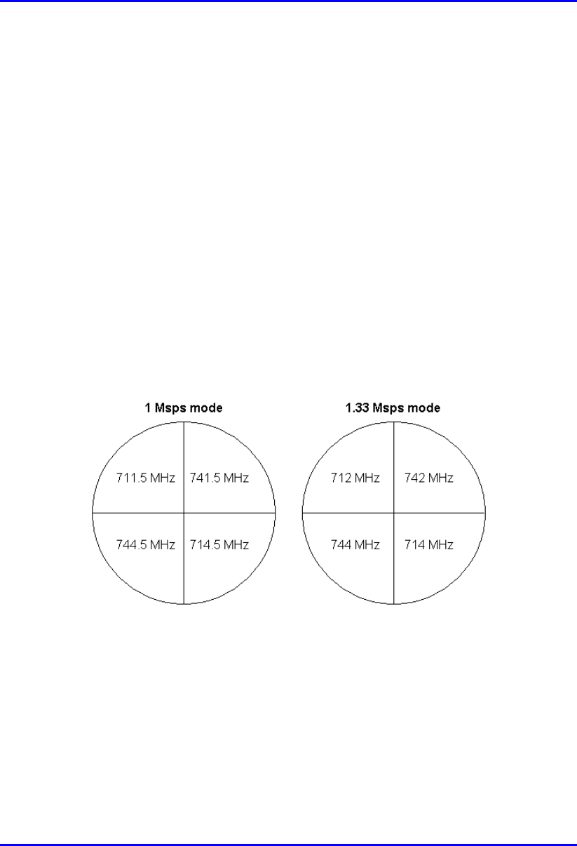
In the 1 Megasymbols per second (Msps) mode, the center frequencies are 711.5,
712.5, 713.5, 714.5, 741.5, 742.5, 743.5, and 744.5. Thus, the frequency allocation
for four BSRs is 711.5, 741.5, 714.5, and 744.5.
In the 1.33 Msps mode, the center frequencies are 712, 713, 714, 742, 743, and 744.
Thus, the frequency allocation for four BSRs is 712, 742, 714, and 744.
Figure 5-3: Frequency allocation in a four-sector Base Station
Radio interference may occur between the BSRs operating in the upper frequency
range (i.e. 742 MHz and 744 MHz) and the lower frequency range (i.e. 712 MHz
and 714 MHz). To overcome this interference, a 1-meter vertical separation is
recommended between the BSRs operating in the upper frequency and the BSRs
operating in the lower frequency.

Part I
Part IPart I
Part I
Base Station Installation
Base Station InstallationBase Station Installation
Base Station Installation
Part I describes the procedures for installing the ASWipLL devices located at the
Base Station, and includes the following chapters:
! Chapter 6, “Basic Design of Devices”
! Chapter 7, “Mounting the Devices”
! Chapter 8, “Network Cabling”
! Chapter 9, “Serial Cabling”
! Chapter 10, “Connecting Third-Party External Antennas”
! Chapter 11, “Power Cabling”
This page is intentionally left balnk.

02030311-07 Airspan Networks Inc. 6-1
Basic Design of Devices
Basic Design of DevicesBasic Design of Devices
Basic Design of Devices
This chapter describes the basic design of the ASWipLL devices that can be
installed at the Base Station:
! BSR
! BSDU
! SDA-1/48V
! GPS
! BSPS
6.1. BSR
The BSR is an encased outdoor radio providing access to the BSR’s communication
ports on its front panel. The BSR’s bottom panel provides holes for mounting the
BSR to, for example, a pole or wall.
6.1.1. Physical Dimensions
The BSR’s physical dimensions are described in the table below.
Table 6-1: BSR physical dimensions
Parameter Value Comment
Height 400 mm (15.74 inches)
Width 317 mm (12.48 inches)
Depth 65.5 mm (2.58 inches)
Weight 4.7 kg
The BSR’s physical dimensions
exclude the mounting kit
6
Basic Design of Devices Hardware Installation Guide
6-2 Airspan Networks Inc. 02030311-07
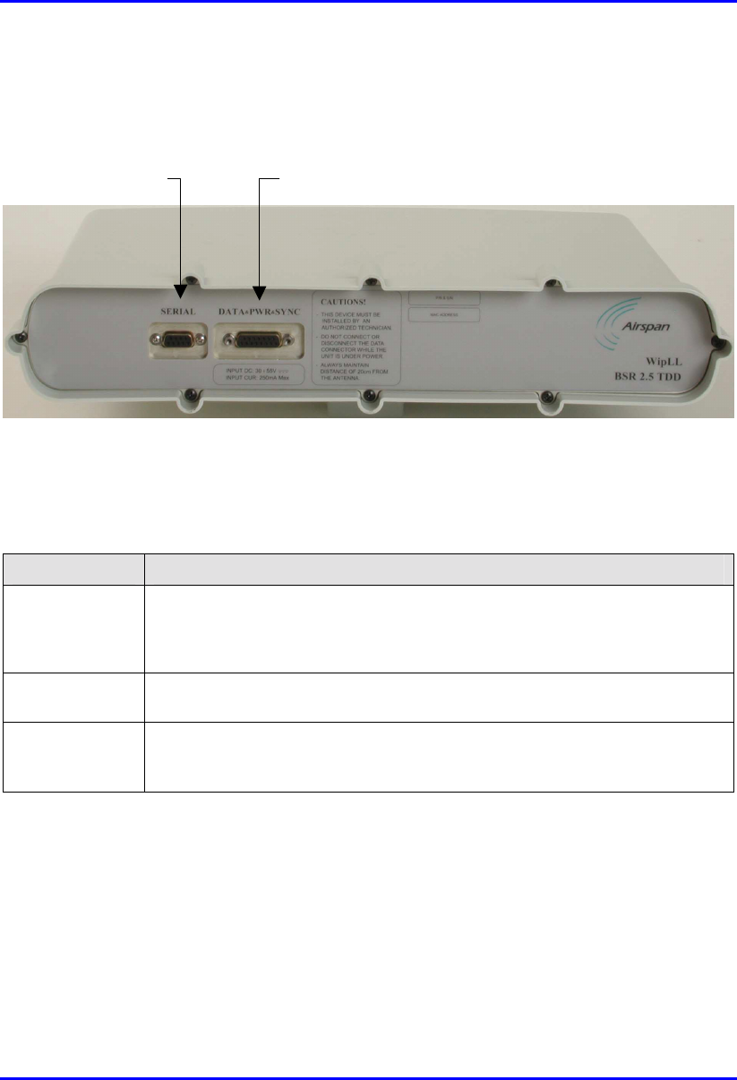
6.1.2. Ports
The BSR provides various ports on its front panel, as displayed below:
Figure 6-1: BSR front panel (built-in antenna model)
The table below describes the BSR ports.
Table 6-2: BSR ports
Port Interface
15-pin D-type • Ethernet (10BaseT): with the BSDU (or SDA)
• Synchronization: of BSRs controlled by BSDU
• Power: supplied by BSDU (or SDA)
9-pin D-type Serial (RS-232) local initial configuration (using WipConfig tool) during
installation
N-type For attaching third-party external antennas. BSR models for the 700 and 900
MHz bands provide two N-type ports. BSR models with built-in antennas do
not provide N-type ports.
9-pin D-type port 15-pin D-type port

02030311-07 Airspan Networks Inc. 7-1
Mounting the Devices
This chapter describes the mounting procedures for the following devices:
BSR
BSDU
SDA-1/48V
BSPS
7.1. Pole-Mounting the BSR
The BSR is typically mounted on a pole, however, it can be wall mounted as well.
Pole mounting allows the BSR to be easily adjusted in the horizontal (azimuth) and
vertical (elevation) planes for antenna alignment.
Note: In the standard BSR kit, Airspan does not supply wall-mounting
brackets. To order wall-mounting brackets, contact your Airspan
representative. BSR wall mounting is identical to SPR wall mounting.
Therefore, for a detailed description of wall mounting, see SPR wall mounting
in Part II, Chapter 13, "Mounting the Devices".
The BSR is mounted using the mounting holes located on the BSR’s bottom panel
(see Figure 7-1) and the supplied pole-mounting brackets. The pole-mounting
bracket is designed to support the BSR on a round pole of 45 mm in diameter.
7
Mounting the Devices Hardware Installation Guide
7-2 Airspan Networks Inc. 02030311-07
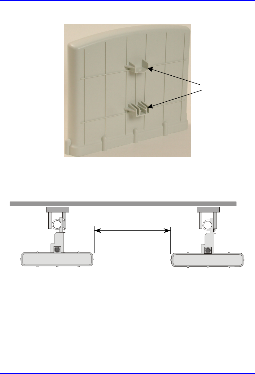
Figure 7-1: BSR bottom panel providing holes for mounting
To prevent radio interference, each BSR requires a minimum of 1-metre separation
between adjacent BSRs (see Figure 7-2).
1 Metre min.
Figure 7-2: Minimum separation between mounted BSRs
Mounting holes
Hardware Installation Guide Mounting the Devices
02030311-07 Airspan Networks Inc. 7-3
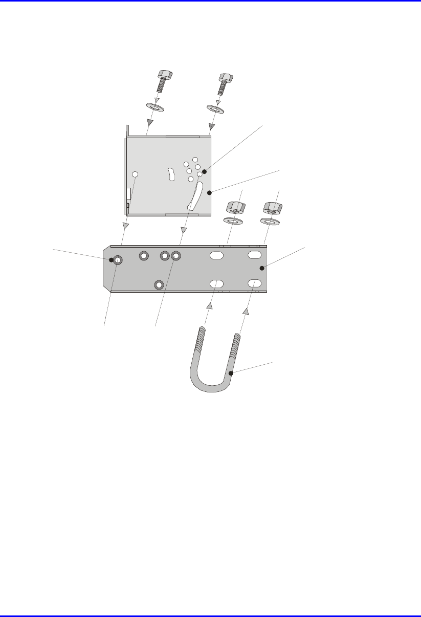
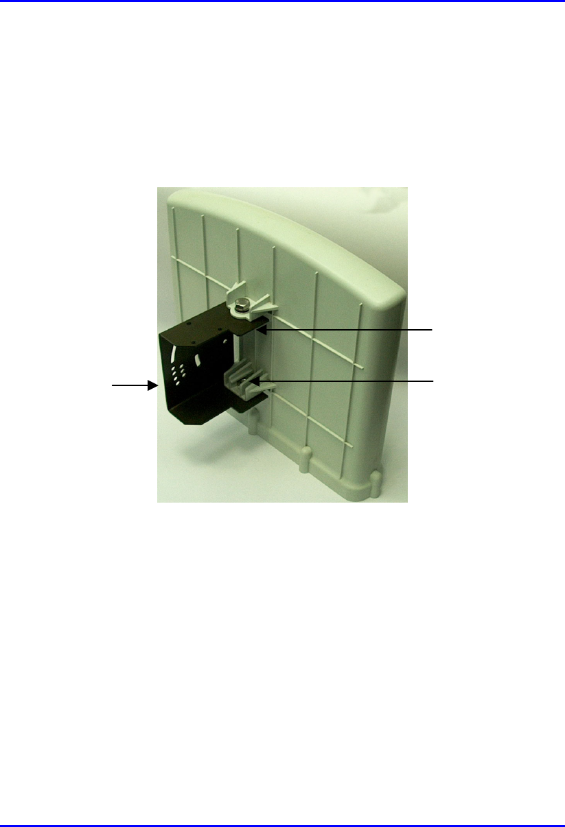
A summary of the BSR pole-mounting procedure is displayed below.
Pivot Hole
‘U’ Bolt
Locking Holes
BSR mounting
Bracket
Clamping Bracket
Figure 7-3: Attaching BSR pole-mounting brackets
To pole mount the BSR:
1. Attach the mounting bracket to the BSR:
a. Align the mounting bracket with the BSR's mounting holes so that the
mounting bracket's side with the built-in nut is aligned with the BSR's
mounting holes furthest from the BSR's front panel, as shown in the figure
below.
Mounting the Devices Hardware Installation Guide
7-4 Airspan Networks Inc. 02030311-07
b. Slide an M10 flat washer and M10 spring lock washer onto an M10 hex head
screw (ensure spring lock washer is closest to the bolt's head). From the
external side, insert the M10 hex head screw through the mounting bracket
and BSR's mounting holes. Fasten the M10 hex head screw (one is provided
with a built-in nut while the other requires you to insert an M10-hex nut into
the BSR's mounting hole).
Figure 7-4: Mounting bracket connected to BSR
2. Attach the clamping bracket to the mounting bracket:
a. Slide an M6 spring lock washer onto an M6 hex head screw. Align the
mounting bracket's and clamping bracket's pivot holes, such that the
clamping bracket is aligned to the the inside of the mounting bracket. From
the external side of the mounting bracket, insert the M6 hex head screw into
the pivot holes and then fasten, but not tightly. (The clamping bracket
provides a built-in nut.)
BSR's mounting
hole with built-in
nut holder
Mounting bracket
with built-in nut
Mounting
b
racket
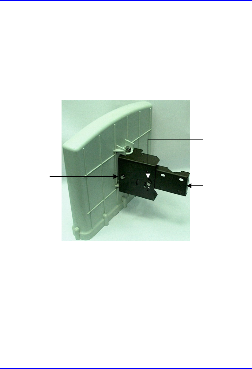
Hardware Installation Guide Mounting the Devices
02030311-07 Airspan Networks Inc. 7-5
b. Choose an elevation hole on the mounting bracket and then align it with the
corresponding hole on the clamping bracket. Slide an M6 spring lock washer
onto an M6 hex head screw, and then from the external side of the mounting
bracket, insert the M6 hex head screw through the elevation hole on the
mounting bracket and into the clamping bracket's corresponding hole. Fasten
but not tightly the M6 hex head screw (the clamping bracket provides built-
in nut). The elevation hole can later be changed according to desired antenna
orientation in the elevation plane.
Figure 7-5: Clamping bracket attached to mounting bracket
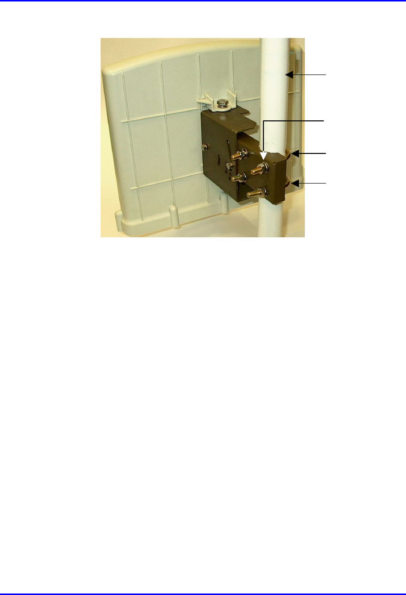
3. Attach the U-bolt to the pole:
a. Place one U-bolt around the pole, and then insert the U-bolt screw side
through the two corresponding holes (horizontally parrallel) on the clamping
bracket. Slide an M8 flat washer and M8 spring lock washer onto each U-
bolt screw side (ensure that the flat washer is adjacent to the clamping
bracket). Fasten each U-bolt side with the two M8 hex nuts.
b. Attach the second U-bolt as described above.
Pivot hole
Clamping
b
racket
Selected
elevation hole
Mounting the Devices Hardware Installation Guide
7-6 Airspan Networks Inc. 02030311-07
Figure 7-6: Attaching BSR to pole using U-bolts
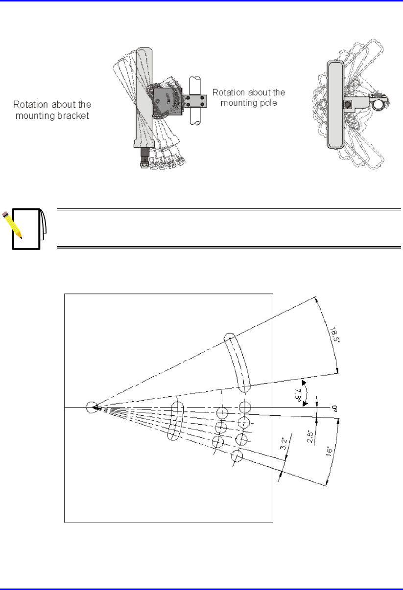
4. Perform final BSR orientation:
a. Adjust the vertical position of the BSR by choosing a final elevation hole as
described in Step 2. Lock the BSR at the desired position by inserting the
locking bolt in the desired position and fastening it tightly. Fasten tightly the
bolt in the pivot hole. See Figure 7-8 for a description of the angles (in
degrees) of each elevation hole.
b. Adjust the horizontal position of the BSR by rotating the BSR about the
pole, and then tightening the nuts of the U-bolts.
BSR positioning is obtained in two planes by adjustment of the mounting
bracket assembly a shown in Figure 7-7.
U-
b
olt
U-
b
olt
Fastened by
screws and
washers
Pole
Hardware Installation Guide Mounting the Devices
02030311-07 Airspan Networks Inc. 7-7
Figure 7-7: BSR orientation in vertical (top figure) and horizontal plane (lower figure)
Note: A thread-locking compound is to be used to prevent the bolts working
loose. A loop should be left in the cable for maintenance purposes and to
prevent the cable weight being taken directly on the connector.
The figure below displays the possible angles of elevation. As is shown, the BSR
pole mounting bracket allows elevation between -18.5° to 26.3°.
Figure 7-8: Orientating BSR in the elevation plane (side view of BSR)
Mounting the Devices Hardware Installation Guide
7-8 Airspan Networks Inc. 02030311-07
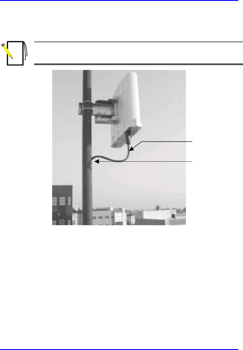
Note: It is important to provide strain relief and drip loop for Cat-5 cables. Create
a drip loop and strain relief using cable tie, to tie cable to pole, as displayed in the
figure below.
Figure 7-9: Pole-mounted BSR with cable drip loop and strain relief
Drip loop and
strain relief
Cable tie

Hardware Installation Guide Mounting the Devices
02030311-07 Airspan Networks Inc. 7-9
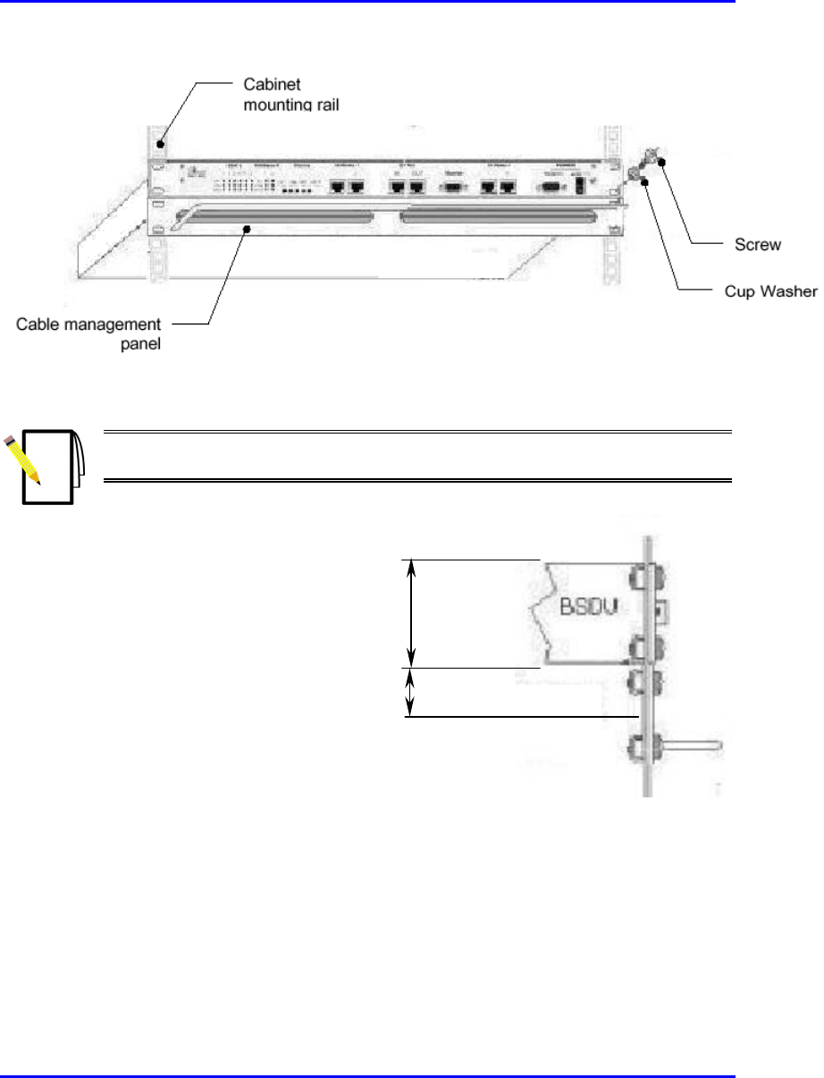
7.2. Rack Mounting the BSDU
The BSDU is designed for mounting in a standard 19-inch (48.3 cm) equipment rack
or telco rack with 1 rack unit (1-U) of vertical rack space. The sides of the BSDU
chassis provide integrated front-rail mounting brackets. Therefore, all that is
required for mounting the BSDU is to attach the BSDU front-rail mounting brackets
to the rack. The mounting brackets are secured to the rack's mounting rails using the
supplied four M5 mounting screws and plastic cup washers.
To rack-mount the BSDU:
1. Determine which rack rail holes—left and right side—will be used for attaching
the chassis.
2. Insert four nuts into the rack's rail holes you designated in Step 1. These nuts are
housed in Tinnerman clips, which allow you to fasten them into the rail holes.
To insert the Tinnerman clips, hold the clips, squeeze them, and then insert them
into the rail hole.
3. Carefully insert the BSDU into the rack, aligning the BSDU’s mounting bracket
holes with the rack rail holes.
4. Insert the M5-mounting screws, with plastic washers, into the BSDU mounting
bracket holes, on each side, as shown in Figure 7-10. In this way, the chassis is
supported until you tighten the chassis screws.
5. Tighten the M5 mounting screws to fasten the chassis to the cabinet.
Mounting the Devices Hardware Installation Guide
7-10 Airspan Networks Inc. 02030311-07
Figure 7-10: BSDU rack mounting
Note: When mounting multiple BSDUs in a cabinet, vertical spacing—above
and below—is required for feeding cables to the rear.
Figure 7-11: BSDU and vertical space for cables
7.3. Mounting the SDA-1/48V
The SDA-1/48V is simply placed on a desktop. In other words, no mounting is
involved.
Space for cable management
1U-chassis

Hardware Installation Guide Mounting the Devices
02030311-07 Airspan Networks Inc. 7-11
7.4. Mounting the BSPS (Optional)
The BSPS is supplied pre-mounted in a standard 19” x 11U rack, providing
available space for additional equipment (i.e. BSDUs, which require 1U each). Thus,
no mounting procedures are needed.

Mounting the Devices Hardware Installation Guide
7-12 Airspan Networks Inc. 02030311-07
This page is intentionally left blank.

02030311-07 Airspan Networks Inc. 8-1
Network Cabling
Network CablingNetwork Cabling
Network Cabling
Network cabling at the Base Station depends on the ASWipLL devices implemented
at the Base Station to provide the BSR with connectivity to the provider's backhaul
and power source. These devices can be one of the following:
! SDA: Base Station providing AC power supply and consisting of a single BSR
! BSDU: Base Station consisting of multiple BSRs
! SDA-1/48V: Base Station providing DC power supply and consisting of a single
BSR
8
Network Cabling Hardware Installation Guide
8-2 Airspan Networks Inc. 02030311-07
8.1. BSR Connected to an SDA
An SDA is typically implemented at Base Stations that consist of only a single BSR.
The SDA provides Ethernet interface between the BSR and the provider's backhaul
network.
Notes:
1) The SDA is typically implemented at the subscriber's site with the SPR.
For a detailed description of installing the SDA, see Part 2, "CPE Installation –
SPR".
2) The SDA also supplies –48 VDC power to the BSR.
8.1.1. Connecting BSR to SDA
The BSR outdoor radio is connected to the indoor SDA device by a standard CAT 5
cable.
The following lists the BSR-to-SDA cable setup:
! Cable: straight-through CAT-5 (100 meters) 4 Pair outdoor type – 24 AWG
! Connectors:
! BSR side: 15-pin D-type male (only 8 pins are used)
! SDA side: 15-pin D-type male (only 8 pins are used)
Notes:
1) The maximum cable length between the BSR and SDA is 100 meters.
2) Airspan supplies unterminated CAT 5 cables for 15-pin D-type connectors.
For a detailed description on crimping cables, see Appendix C, “Cable Crimping".
Hardware Installation Guide Network Cabling
02030311-07 Airspan Networks Inc. 8-3
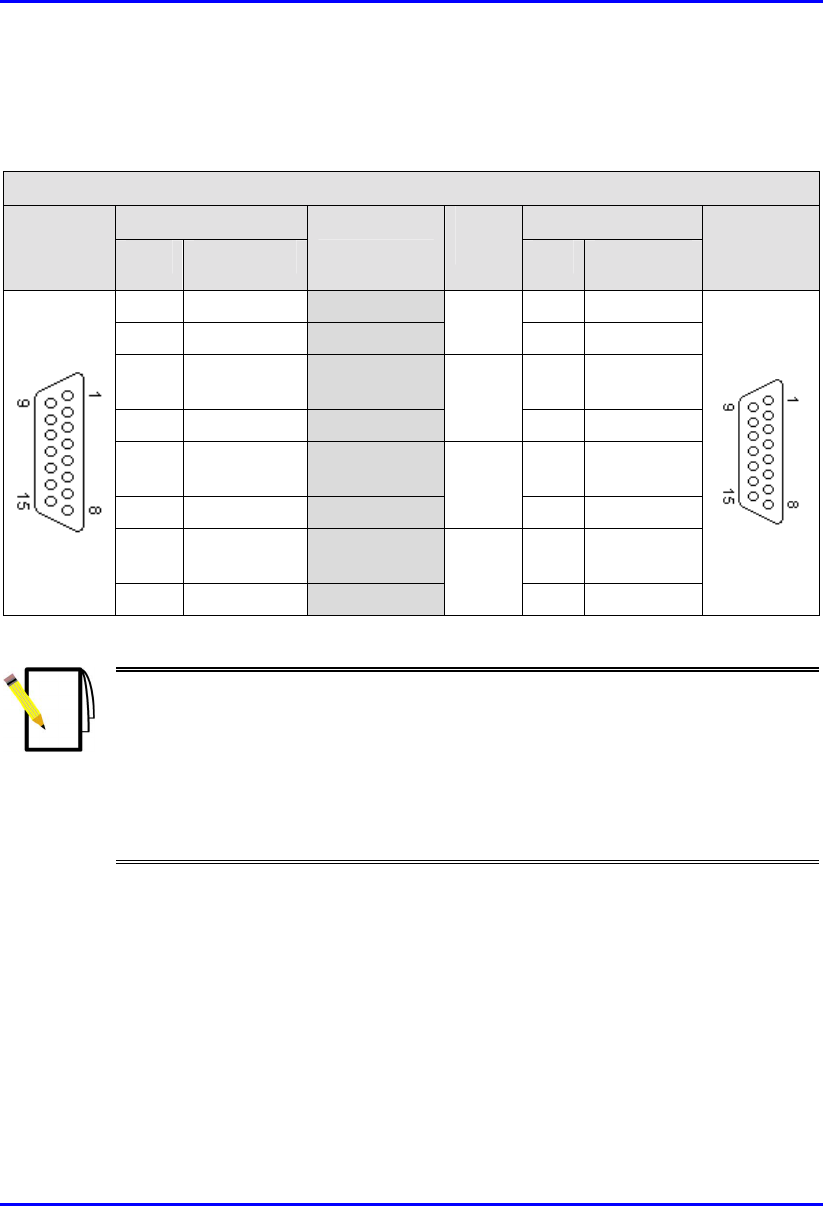
! Connector pinouts:
Table 8-1: BSR-to-SDA cable connector pinouts
Straight-through CAT-5 UTP PVC 4 Pair 24 AWG cables
BSR SDA
15-pin
D-type
male Pin Function
Wire color Wire
pair Pin Function
15-pin
D-type
male
1 +48 VDC Blue / White 1 +48 VDC
2 48 RTN Blue 1 2 48 RTN
3 Tx+ Orange /
White
3 Rx+
4 Tx- Orange
2
4 Rx-
5 Rx+ Green /
White
5 Tx+
6 Rx- Green
3
6 Tx-
Notes:
1) Only pins 1 to 6 are used.
2) The wire color-coding is ASWipLL's standard for wire color-coding (for a
detailed description of ASWipLL's wire color-coding standard, see Appendix C,
"Cable Crimping"). However, if you implement your company's wire color-
coding scheme, ensure that the wires are paired and twisted according to the
pin functions listed in Table 8-1 (e.g. Rx+ with Rx-).
Network Cabling Hardware Installation Guide
8-4 Airspan Networks Inc. 02030311-07
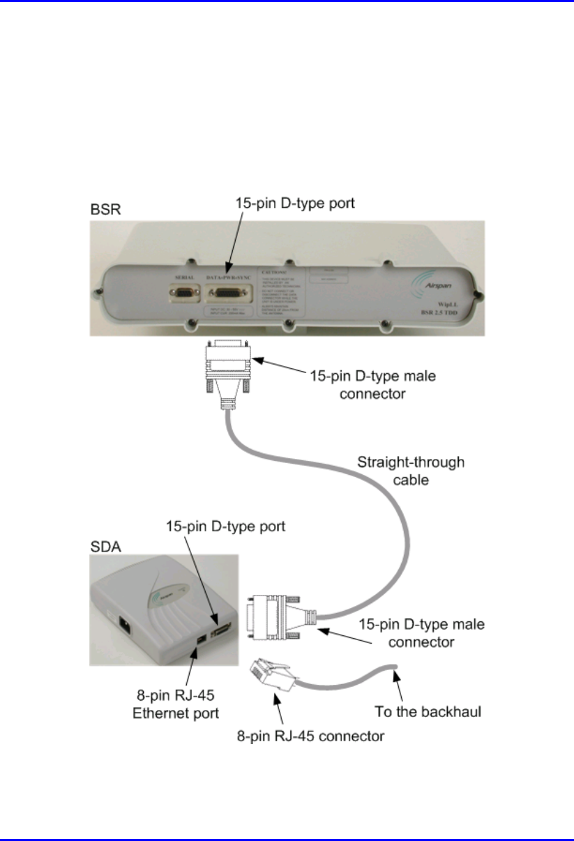
To connect the BSR to the SDA:
1. Connect the 15-pin D-type male connector, at one end of the CAT 5 cable, to
the BSR’s 15-pin D-type port, labeled DATA POWER SYNC.
2. Connect the 15-pin D-type male connector, at the other end of the CAT 5 cable,
to the SDA.
Figure 8-1: Connecting BSR to SDA

Hardware Installation Guide Network Cabling
02030311-07 Airspan Networks Inc. 8-5
8.1.2. Connecting SDA to Provider's Ethernet
Network
The SDA is typically implemented at the subscriber's premises with the SPR. For a
detailed description of connecting the SDA to the Ethernet network, see Part 2,
Chapter 14, "Network Cabling".
8.2. BSR Connected to a BSDU
Multiple BSRs at a Base Station interface with the the provider's backhaul network
through the BSDU. Each BSDU can support up to six BSRs, and each Base Station
can support up to four BSDUs. Thus, at full configuration, 24 BSRs (i.e. 4 BSDUs
multiplied by 6 BSRs) can be implemented at a Base Station.
8.2.1. Connecting BSR to BSDU
The BSR’s 15-pin D-type port is connected to one of the six BSDU’s rear panel 15-
pin D-type ports (labeled BSR #).
The BSR-to-BSDU cable setup is as follows:
! Cable: straight-through 10Base-T Ethernet 4 Pair Cat 5 outdoor type – 24 AWG
(100 meters)
! Connectors:
! BSR side: 15-pin D-type male (only 8 pins are used)
! BSDU side: 15-pin D-type male (only 8 pins are used)
Note: Airspan supplies unterminated CAT 5 cables for 15-Pin D-type
connectors. For a detailed description on crimping cables, see Appendix C,
“Cable Crimping".
Network Cabling Hardware Installation Guide
8-6 Airspan Networks Inc. 02030311-07
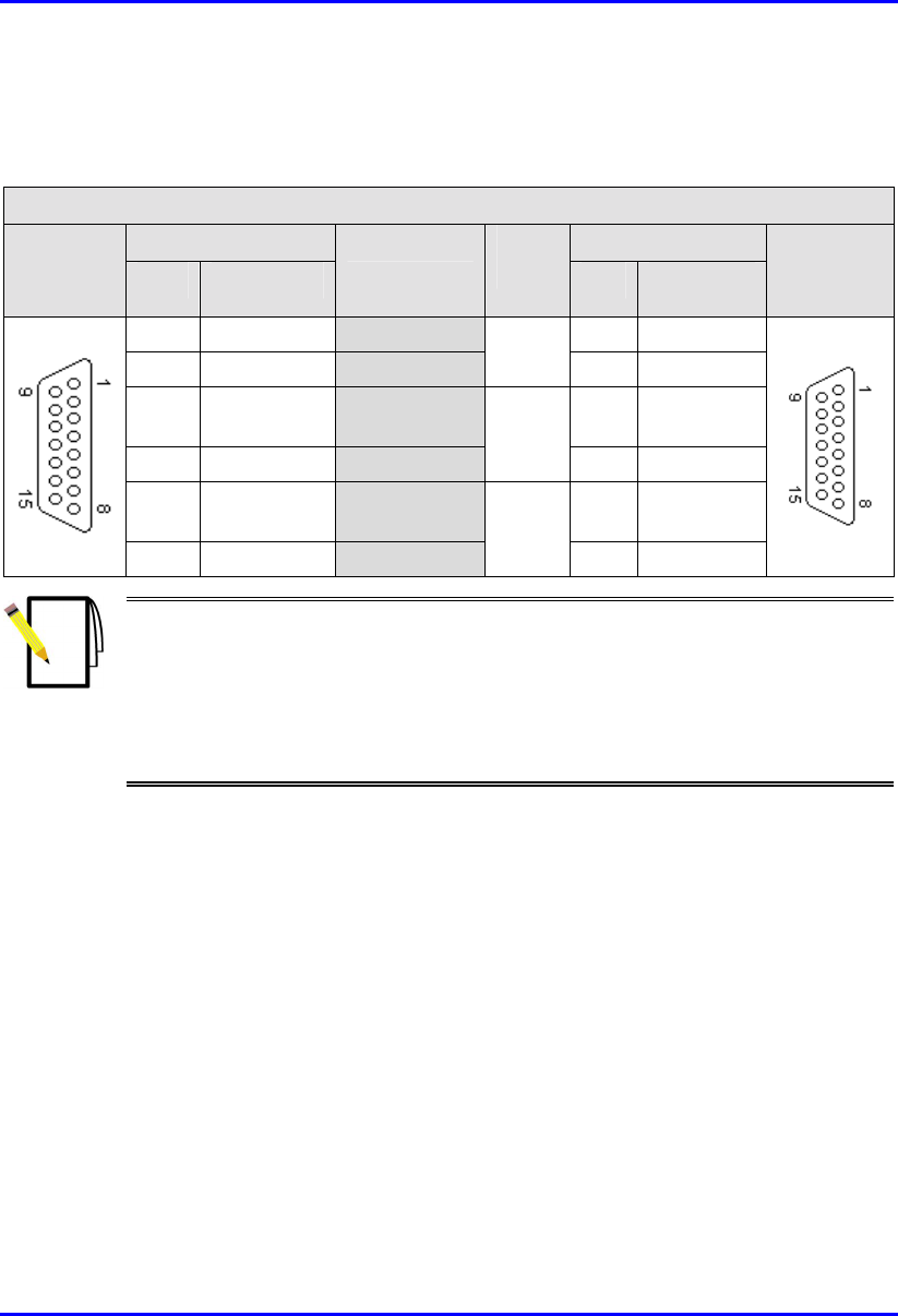
! Connector pinouts:
Table 8-2: BSR-to-BSDU cable connector pinouts
Straight-through CAT-5 UTP PVC 4 Pair 24 AWG cables
BSR BSDU
15-pin
D-type
male Pin Function
Wire color Wire
pair Pin Function
15-pin
D-type
male
1 +48 VDC Blue / White 1 +48 VDC
2 48 RTN Blue 1 2 48 RTN
3 Tx+ Orange /
White
3 Rx+
4 Tx- Orange
2
4 Rx-
5 Rx+ Green /
White
5 Tx+
6 Rx- Green
3
6 Tx-
7 Sync.+ Brown /
White
7 Sync.+
8 Sync.- Brown
4
8 Sync.-
Notes:
1) Only pins 1 to 8 of the 15-pin D-type connector are used.
2) The wire color-coding described in the table is ASWipLL's standard for wire
color-coding (for a detailed description of ASWipLL's wire color-coding
standard, see Appendix C, "Cable Crimping"). However, if you implement your
company's wire color-coding scheme, ensure that the wires are paired and
twisted according to the pin functions listed in the table above to prevent
electrical interference between the transmitter pins (e.g. Rx+ with Rx-).
To connect the BSR to the BSDU (Figure 8-2):
1. Connect the 15-pin D-type male connector, at one end of the CAT 5 cable, to
the BSR’s 15-pin D-type port labeled DATA POWER SYNC.
2. Connect the 15-pin D-type male connector, at the other end of the CAT-5 cable,
to one of the six BSDU’s 15-pin D-type ports labeled BSR, located at the rear of
the BSDU.

02030311-07 Airspan Networks Inc. 9-1
Serial Cabling
Serial CablingSerial Cabling
Serial Cabling
This chapter describes serial cabling for the following devices:
! BSR
! BSDU
! BSPS
9
Serial Cabling Hardware Installation Guide
9-2 Airspan Networks Inc. 02030311-07
9.1. Serial Cabling BSR to a PC
The BSR provides an RS-232 port for serial interface with a PC. This serial interface
allows you to perform local BSR configuration using WipConfig.
Notes:
1) For serial configuration, the BSR must remain connected to the BSDU/SDA
(i.e. the BSR’s 15-pin D-type port remains connected to the BSDU’s/SDA’s 15-
pin D-type port).
2) For a detailed explanation on performing BSR initial configuration, refer to
WipConfig User’s Guide or WipConfig PDA User’s Guide.
The following lists the BSR-to-PC serial cabling:
! Cable: crossover serial cable
! Connectors:
! BSR side: 9-pin D-type male
! PC side: 9-pin D-type female
! Connector pinouts:
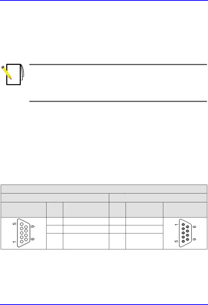
Table 9-1: BSR-to-PC serial connector pinouts
Crossover serial cable
BSR PC
9-pin D-type
male
Pin Function Pin Function 9-pin D-type
female
2 RS232 Rx 3 Tx
3 RS232 Tx 2 Rx
5 GND 5 GND
Note: Pins not mentioned are not connected.
Hardware Installation Guide Serial Cabling
02030311-07 Airspan Networks Inc. 9-3
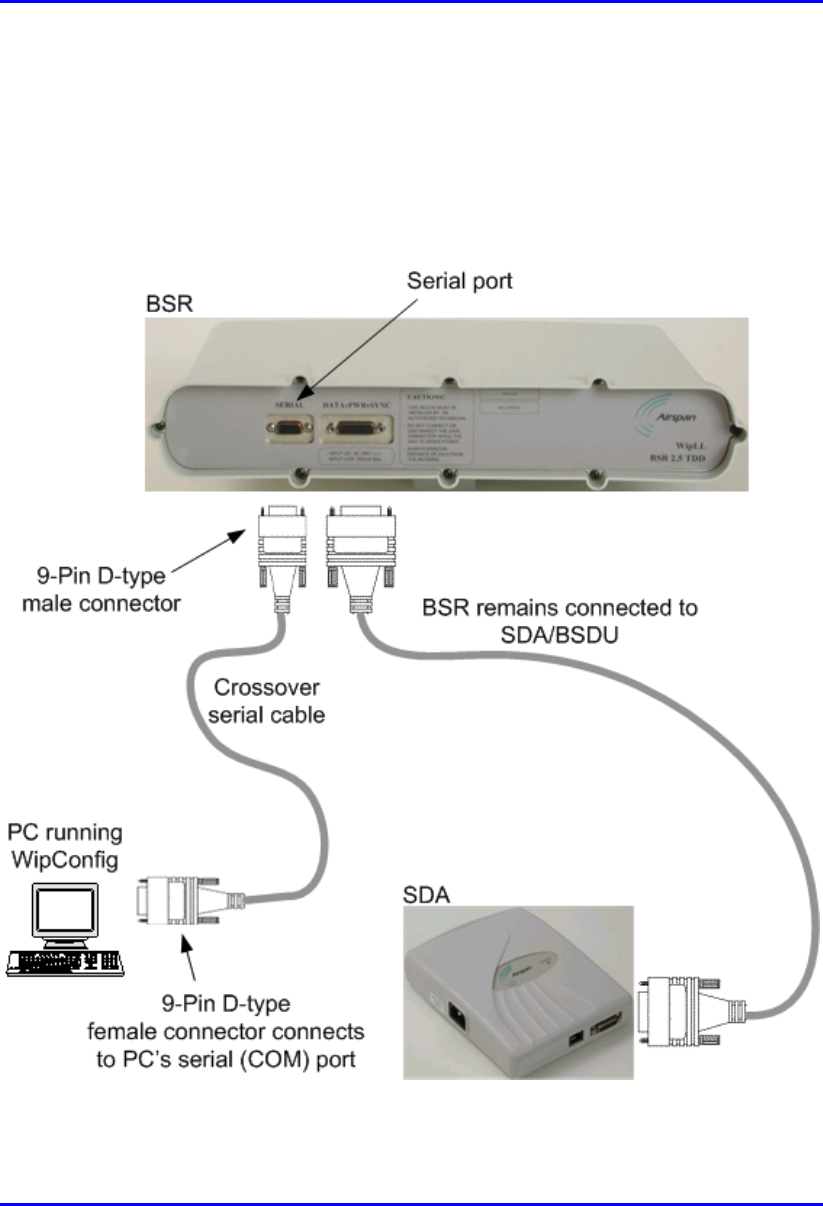
To connect the BSR to a PC for serial configuration (see Figure 9-1):
1. Connect the 9-pin D-type male connector, at one end of the serial cable, to the
BSR’s serial port, labeled Serial.
2. Connect the 9-pin D-type female connector, at the other end of the serial cable,
to the PC’s serial port.
Figure 9-1: BSR-to-PC serial cabling (e.g. of BSR connected to SDA)

02030311-07 Airspan Networks Inc. 10-1
Connecting Third
Connecting ThirdConnecting Third
Connecting Third-
--
-Party
Party Party
Party
External Antennas
External AntennasExternal Antennas
External Antennas
This chapter describes the procedures for connecting third-party external radio and
Global Positioning System (GPS) antennas to the BSR and BSDU respectively. The
implementation of these antennas depends on the BSR model (with respect to radio
antennas) and the need for synchronization of the ASWipLL system (with respect to
GPS antennas).
10.1. Connecting Radio Antennas to BSR
The BSR model without a built-in radio antenna provides an N-type port(s) for
connecting a third-party external antenna(s). The BSR models for the 900 MHz and
700 MHz bands provide two N-type connectors for connecting two third-party
external antennas. Two antennas provide dual-antenna diversity, whereby data is
transmitted using only the main antenna, while data is received by the antenna (main
or secondary) with the best radio frequency (RF) reception.
Warning: It is the responsibility of the person installing the ASWipLL system
to ensure that when using the outdoor antenna kits in the United States (o
r
where FCC rules apply), that only those antennas certified with the product are
used. The use of any antenna other than those certified with the product is
expressly forbidden in accordance with FCC rules CFR47 part 15.204. The
installer should configure the output power level of antennas according to
country regulations and per antenna type.
10
Connecting Third-Party External Antennas Hardware Installation Guide
10-2 Airspan Networks Inc. 02030311-07
Warning: For ASWipLL 700 (i.e. 700 MHz band), where four BSRs are
installed at a Base Station, a 1-meter separation must be provided between the
antennas of the BSRs operating in the lower frequencies (i.e. 711.5 and 714.5
for 1 Msps mode; and 712 and 714 for 1.33 Msps mode) and the antennas of
the BSRs operating in the upper frequencies (i.e. 741.5 and 744.5 for 1 Msps
mode; and 742 and 744 for 1.33 Msps mode).
Warning: In accordance with FCC regulations, ensure that when operating in
unlicensed bands, the external antennas provide a maximum EIRP of 36 dBm
to prevent interference with other radios operating in the unlicensed band. The
EIRP is defined as:
Max. Power Output + Antenna Gain + Cable Loss ≤
≤≤
≤ 36 dBm (EIRP)
The following lists the BSR-to-third party external antenna cable setup:
! Cable (third party): RF coaxial
! Connector (third party): N-type male.
The usage of N-type ports for models (i.e. in 700 MHz and 900 MHz bands)
with two N-type ports:
! If you are using only one antenna, connect the antenna to the N-type port
labeled Primary.
! If you are using two antennas, connect the second antenna to the N-type port
labeled Secondary.
Warnings:
1) Before connecting the external antenna, ensure that the BSR is NOT
connected to the power source.
2) Before powering on the BSR, ensure that some type of equipment such as
an antenna or an RF attenuator is connected to the N-type port. This eliminates
the risk of damaging the BSR device.
Hardware Installation Guide Connecting Third-Party External Antennas
02030311-07 Airspan Networks Inc. 10-3
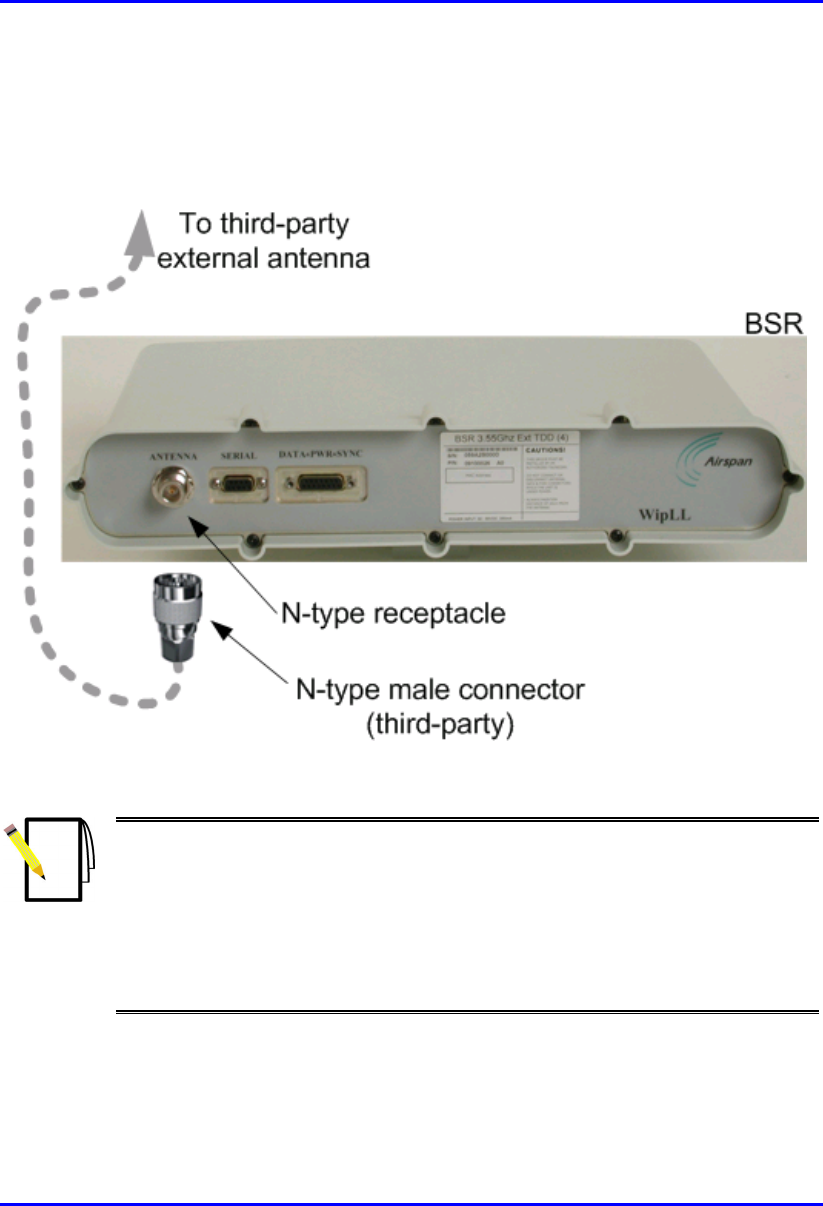
To connect the BSR to a third-party external antenna:
Connect the third-party N-type male connector, at the end of the RF cable, to the
N-type port located on the BSR’s front panel, as displayed in Figure 10-1.
Figure 10-1: Attaching third-party external antenna
Notes:
1) For crimping RF coaxial cables to N-type connectors, see Appendix C,
“Cable Crimping”.
2) Ensure that the third-party antenna cable is of sufficient quality to reduce or
eliminate loss when operating in the required frequency band.
3) For a description of third-party antennas offered by Airspan for BSRs
operating in the 700 MHz and 900 MHz bands, see Appendix G, "Third-Party
Antenna Specifications".

Part II
Part IIPart II
Part II
CPE Installation:
CPE Installation: CPE Installation:
CPE Installation:
Subscriber Premises Radio
Subscriber Premises Radio Subscriber Premises Radio
Subscriber Premises Radio
(SPR)
(SPR)(SPR)
(SPR)
Part II describes the procedures for installing the ASWipLL equipment located at the
subscriber’s premises when implementing an SPR.
Part II includes the following chapters:
! Chapter 12, "Basic Design of Devices"
! Chapter 13, "Mounting the Devices"
! Chapter 14, "Network Cabling"
! Chapter 15, "Serial Cabling"
! Chapter 16, "Connecting Third-Party External Antennas"
! Chapter 17, "Antenna Alignment using RSS LED Adapter"
! Chapter 18, "Power Cabling"
This page is intentionally left blank.

02030311-07 Airspan Networks Inc. 12-1
Basic Design of Devices
Basic Design of DevicesBasic Design of Devices
Basic Design of Devices
This chapter describes the basic design of the ASWipLL devices installed at a
subscriber site when an SPR is implemented:
! SPR
! SDA
! RSS LED Adapter
12
Basic Design of Devices Hardware Installation Guide
12-2 Airspan Networks Inc. 02030311-07
12.1. SPR
This section describes the SPR's basic design.
12.1.1. Physical Dimensions
The SPR’s physical dimensions are described in the following table.
Table 12-1: SPR physical dimensions
SPR model
Parameter Standard Gain
Antenna
High Gain Antenna Comment
Height 311 mm (12.24 inches) 400 mm (15.74 inches)
Width 224 mm (8.82 inches) 317 mm (12.48 inches)
Depth 65.5 mm (2.58 inches) 65.5 mm (2.58 inches)
Weight 2.5 kg 4.7 kg
The SPR’s physical
dimensions exclude the
mounting kit.
SPR models with an N-type
receptacle for attaching a
third-party external antenna
are also available.
Hardware Installation Guide Basic Design of Devices
02030311-07 Airspan Networks Inc. 12-3
12.1.2. Ports
The SPR is an encased outdoor radio providing access to the SPR’s sole
communication port (15-pin D-type) at the front panel (see figure below). The SPR’s
bottom panel provides holes for mounting the SPR to, for example, a pole or wall.
Figure 12-1: SPR (with built-in antennal)
Notes:
1) SPRs without built-in antennas provide an N-type port for connecting a
third-party external antenna.
2) Previous SPR models also provide a 9-pin D-type port for serial interface.
15-pin D-type port

02030311-07 Airspan Networks Inc. 13-1
Mounting the Devices
Mounting the DevicesMounting the Devices
Mounting the Devices
This chapter describes the procedures for mounting the following devices:
! SPR
! SDA
13.1. Wall Mounting the SPR
The SPR is typically mounted on a wall. However, the SPR can also be pole-
mounted. SPR pole mounting is identical to BSR pole mounting, thus, for a detailed
description on pole mounting, see Chapter 7, "Mounting Devices".
Note: The standard SPR kit includes wall-mounting brackets. For ordering
pole-mounting brackets (supply and costs), please contact your Airspan
representative.
13
Mounting the Devices Hardware Installation Guide
13-2 Airspan Networks Inc. 02030311-07
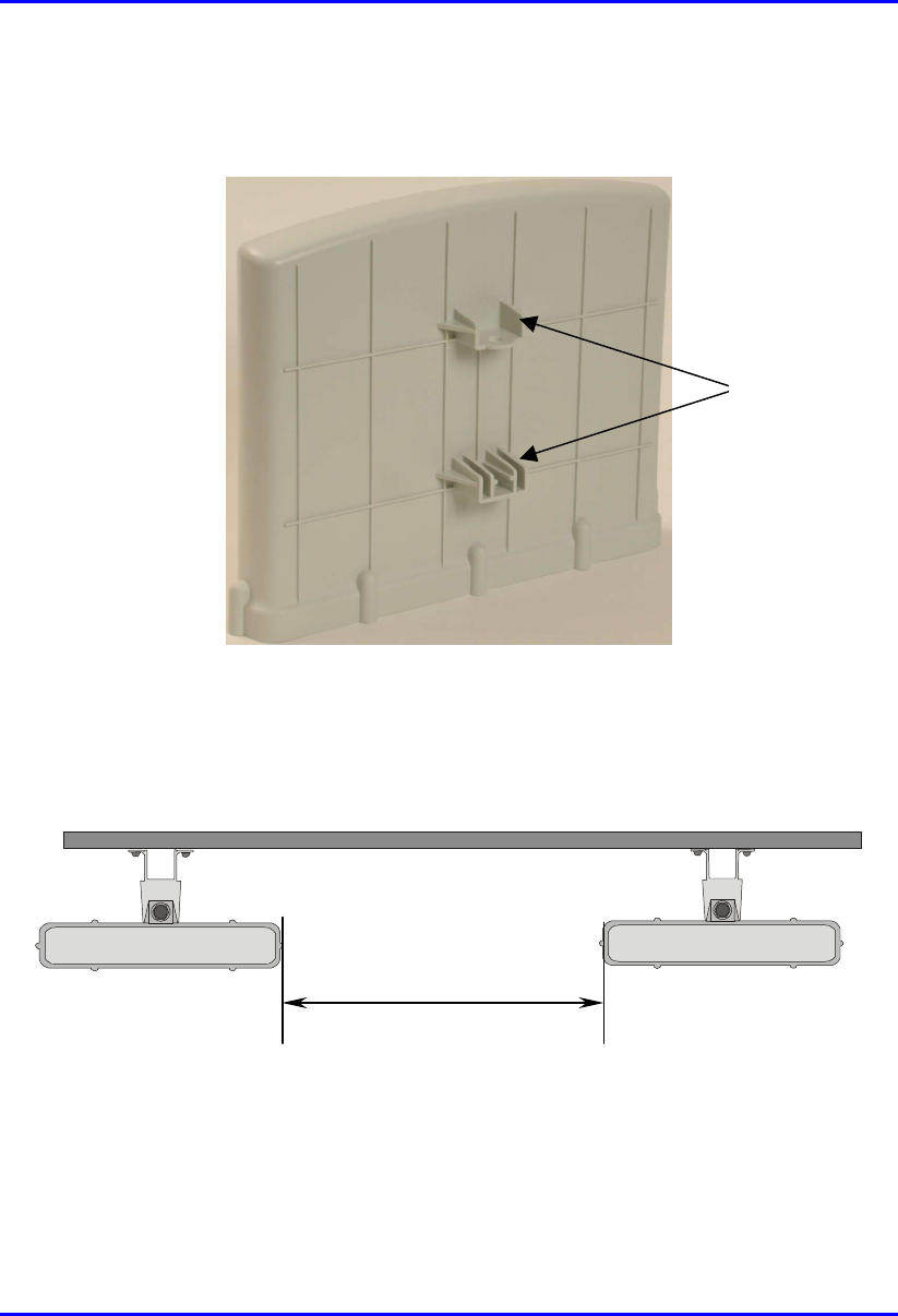
The SPR is mounted using the mounting holes located on the SPR’s bottom panel
(see Figure 13-1), and the wall-mounting brackets (provided).
Figure 13-1: SPR bottom panel providing holes for mounting
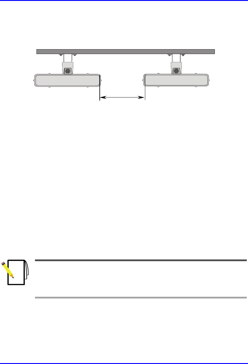
A minimum of 3-meter separation is required between mounted SPRs and existing
customer radio equipment when not transmitting on the same sector (see Figure
13-2).
3.0 metres
Figure 13-2: SPR separation when not transmitting on the same sector
Mounting holes
Hardware Installation Guide Mounting the Devices
02030311-07 Airspan Networks Inc. 13-3
A 1-meter separation is required between SPRs when on the same sector and
transmitting to the same BSR without requiring shielding (see Figure 13-3).
1.0 metre
Figure 13-3: SPR separation when transmitting on the same sector to the same BSR
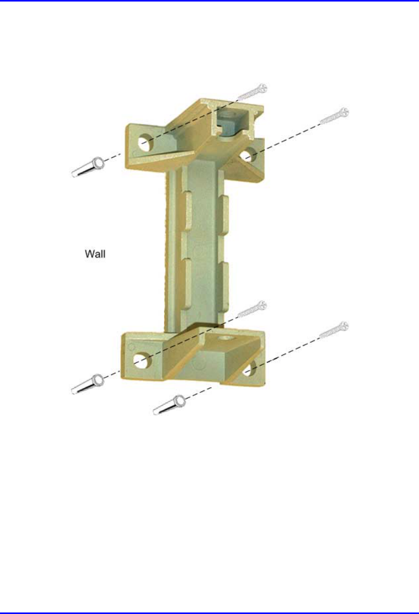
SPR wall mounting is performed in two stages:
! Attaching the mounting bracket to the SPR’s mounting holes.
! Attaching the mounting bracket (attached to the SPR) to the wall.
To wall mount the SPR:
1. Position the mounting bracket on the mounting surface (e.g. wall), and then use a
pencil to mark the position of the four mounting holes.
2. Drill holes for each hole that you marked in the step above.
3. Insert wall anchors (not supplied) into each of the drilled holes.
4. Align the mounting bracket’s four holes with the wall anchors, and then insert a
screw (not supplied) through the mounting bracket holes into each wall anchor,
and tighten.
Note: Airspan does not provide screws for attaching the mounting bracket to
the wall. The screw size depends on the structure of the building to which the
bracket is to be attached. When selecting screw sizes, consideration must be
given to the weight of the SPR and load that may be induced in windy
conditions.
Mounting the Devices Hardware Installation Guide
13-4 Airspan Networks Inc. 02030311-07
The figure below displays relevant dimensions of the mounting bracket. Note the
two different sized fixing holes.
Figure 13-4: Attaching mounting bracket to wall
Hardware Installation Guide Mounting the Devices
02030311-07 Airspan Networks Inc. 13-5
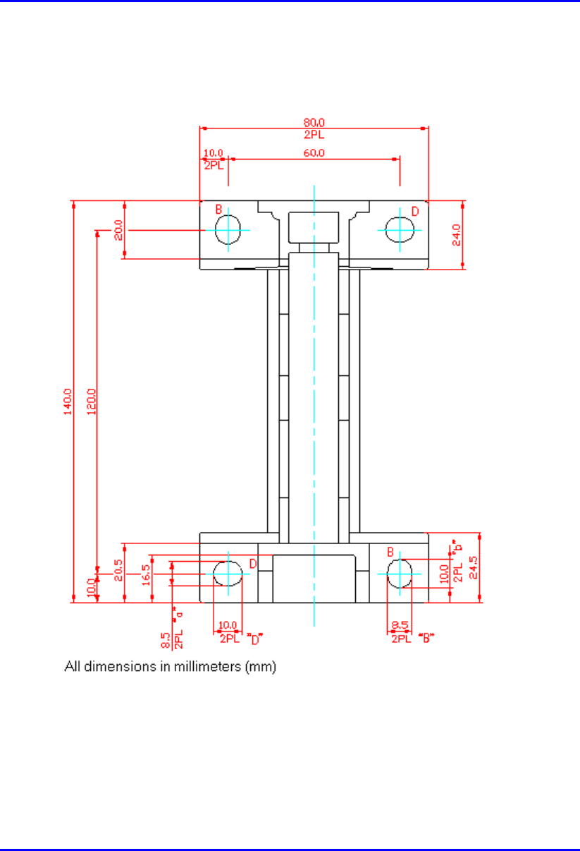
Below is a diagram illustrating the fixing dimensions of the mounting bracket.
Ensure that the distance between the hole centers are 120 mm and 60 mm.
Figure 13-5: SPR mounting bracket dimensions for the four fixing holes
Mounting the Devices Hardware Installation Guide
13-6 Airspan Networks Inc. 02030311-07
5. Attach the SPR to the mounting bracket by performing the following:
a. Slide an M10 spring lock washer and then an M10 plain washer onto each
M10 hex head screw (ensure lock washer is nearest to head of screw bolt).
b. Align the mounting bracket's holes with the BSR's mounting holes as
displayed below. (The mounting bracket side that provides a groove for
inserting a nut must be aligned with the BSR's mounting hole that is nearest
to the BSR's rear panel.)
c. From the external sides, insert the M10 hex head screws through the
mounting bracket's holes and BSR's mounting holes. Loosely fasten with the
M10 hex nuts.
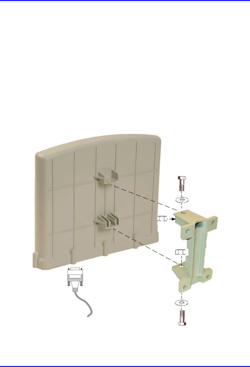
Figure 13-6: Attaching SPR to mounting bracket
Hardware Installation Guide Mounting the Devices
02030311-07 Airspan Networks Inc. 13-7
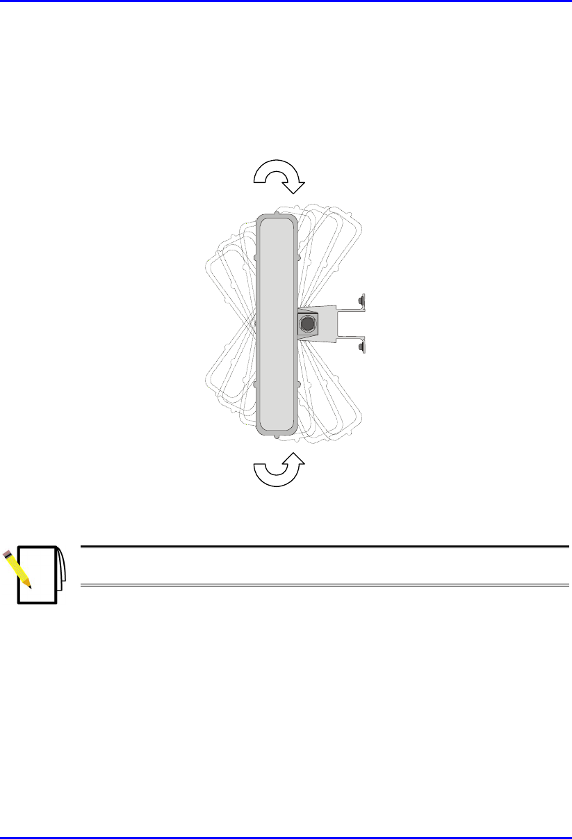
6. Adjust the horizontal positioning of the SPR, and then tighten the two M10 hex
head screws with the M10 hex nuts.
Rotation is restricted in the horizontal plane only. The permissible rotation is
shown in Figure 13-7.
Figure 13-7: Horizontal rotation of the SPR (top view)
Note: A third-party thread-locking compound must be applied to the M10 hex
head screws to prevent the bolts working loose.
02030311-07 Airspan Networks Inc. 15-1
Serial Cabling
Serial CablingSerial Cabling
Serial Cabling
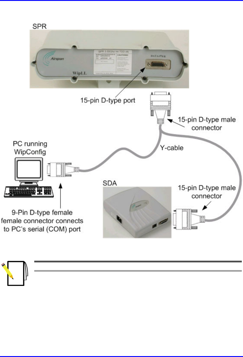
The SPR’s 15-pin D-type port provides serial interface with a PC for configuring the
SPR through an RS-232 communication mode. The 15-pin D-type port uses three
pins for serial interface with the PC, and six pins for interfacing with the SDA (with
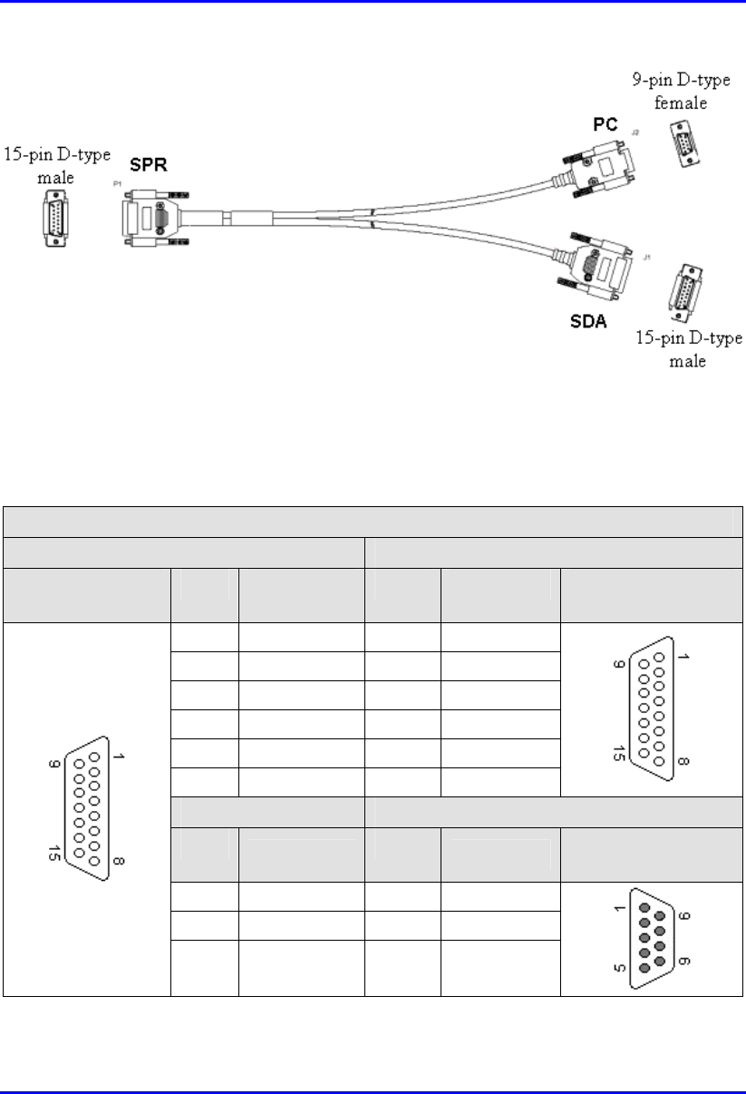
which the SPR is connected). A Y-cable (splitter) is used to connect the SPR's 15-
pin D-type port to both the PC and the SDA.
Note: For performing SPR initial configuration, refer to the ASWipLL
WipConfig User’s Guide.
The SPR-to-PC and SDA cable connections for SPR serial configuration are as
follows:
! Connectors:
! SPR side: 15-pin D-type male (only 6 pins used)
! PC side: 9-pin D-type (RS-232)
! SDA side: 15-pin D-type male
! Cable: straight-through Y-cable
15
Serial Cabling Hardware Installation Guide
15-2 Airspan Networks Inc. 02030311-07
Figure 15-1: Y-cable for serial connection
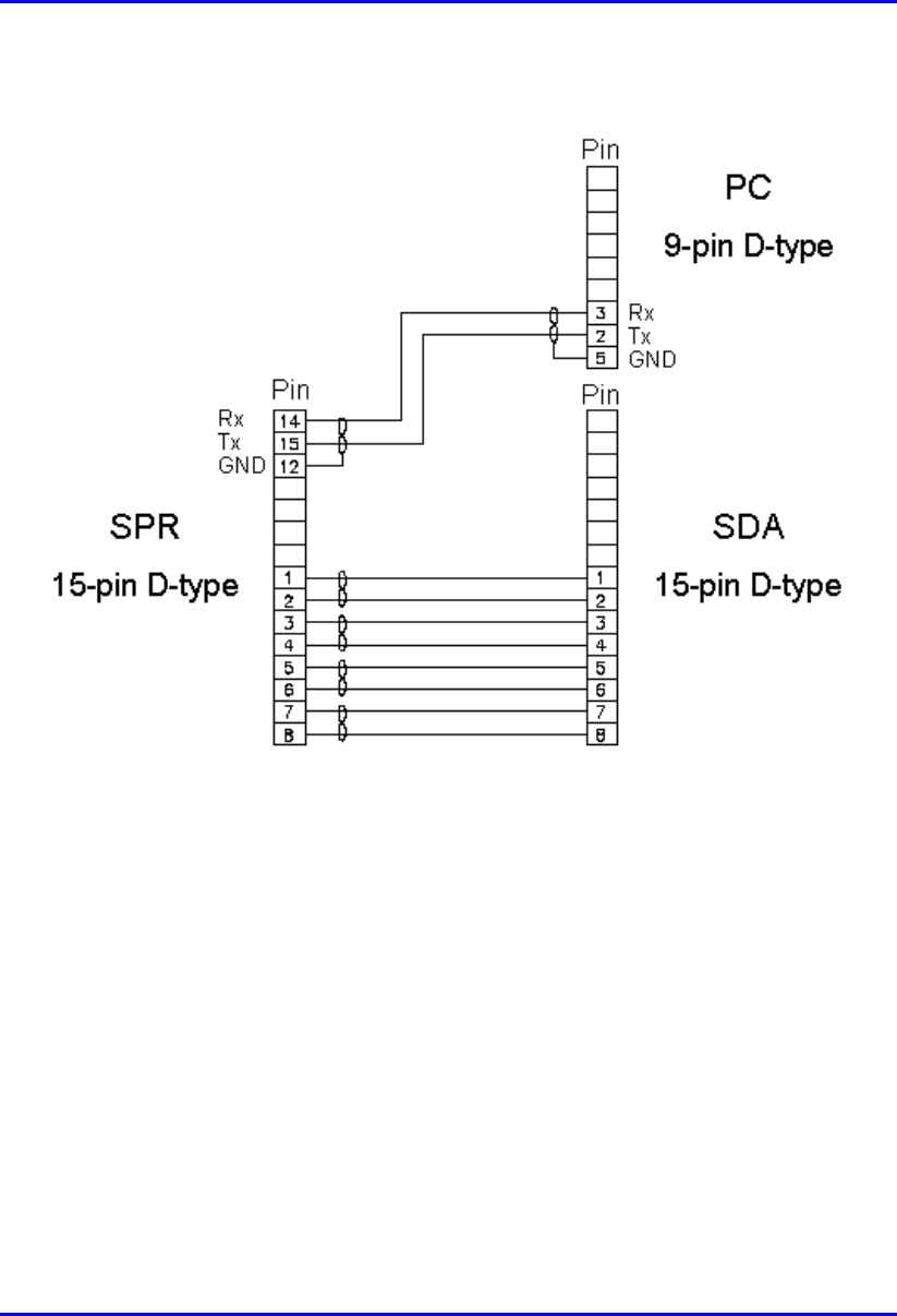
! Connector pinouts:
Table 15-1: Y-cable connector pinouts
Straight-through Y-cable
SPR SDA
15-pin D-type
male
Pin Function Pin Function 15-pin D-type
male
1 +48 VDC 1 +48 VDC
2 48 RTN 2 48 RTN
3 Ethernet Tx+ 3 Rx+
4 Ethernet Tx- 4 Rx-
5 Ethernet Rx+ 5 Tx+
6 Ethernet Rx- 6 Tx-
SPR PC
Pin Function Pin Function 9-pin D-type
female
12 GND 5 GND
14 RS232 Rx 3 Rx
15 RS232 Tx 2 Tx
Hardware Installation Guide Serial Cabling
02030311-07 Airspan Networks Inc. 15-3
The Y-cable connector pin assignments are displayed schematically in Figure 15-2.
Figure 15-2: Y-cable connector pin assignment
To connect the SPR to a PC for serial configuration (see Figure 15-3):
1. Connect the 15-pin D-type male connector, at the one end of the Y-cable, to the
SPR.
2. Connect the 15-pin D-type male connector, at the other end of the Y-cable, to
the SDA.
3. Connect the 9-pin D-type female (RS232) connector, at the other end of the Y-
cable, to the PC’s serial port.
Serial Cabling Hardware Installation Guide
15-4 Airspan Networks Inc. 02030311-07
Figure 15-3: SPR serial cable connections using a Y-cable
Notes: For SPR serial configuration, the SPR remains connected to the SDA.
02030311-07 Airspan Networks Inc. 16-1
Connecting Third
Connecting ThirdConnecting Third
Connecting Third-
--
-Party
Party Party
Party
External Antennas
External AntennasExternal Antennas
External Antennas
The SPR model without a built-in antenna provides an N-type port for connecting a
third-party external antenna. The addition of an external antenna allows greater RF
sector coverage than the standard SPR built-in antenna models.
The following lists the SPR-to-third party external antenna cable setup:
! Cable: RF coaxial
! Connector: N-type male
Warning: Before connecting the external antenna, ensure that the SPR is
NOT connected to the power source.
Warning: Before powering on the SPR, ensure that some type of equipment
such as an antenna or an RF attenuator is connected to the N-type receptacle.
This eliminates the risk of burning the SPR device.
Warning: It is the responsibility of the person installing the ASWipLL system
to ensure that when using the outdoor antenna kits in the United States (or
where FCC rules apply), that only those antennas certified with the product are
used. The use of any antenna other than those certified with the product is
expressly forbidden in accordance with FCC rules CFR47 part 15.204. The
installer should configure the output power level of antennas according to
country regulations and per antenna type.
Warning: In accordance with FCC regulations, ensure that for external
antennas, the maximum EIRP is 36 dBm. The EIRP is defined as:
Max. Power Output + Antenna Gain + Cable Loss ≤
≤≤
≤ 36 dBm (EIRP)
16
Connecting Third-Party External Antennas Hardware Installation Guide
16-2 Airspan Networks Inc. 02030311-07
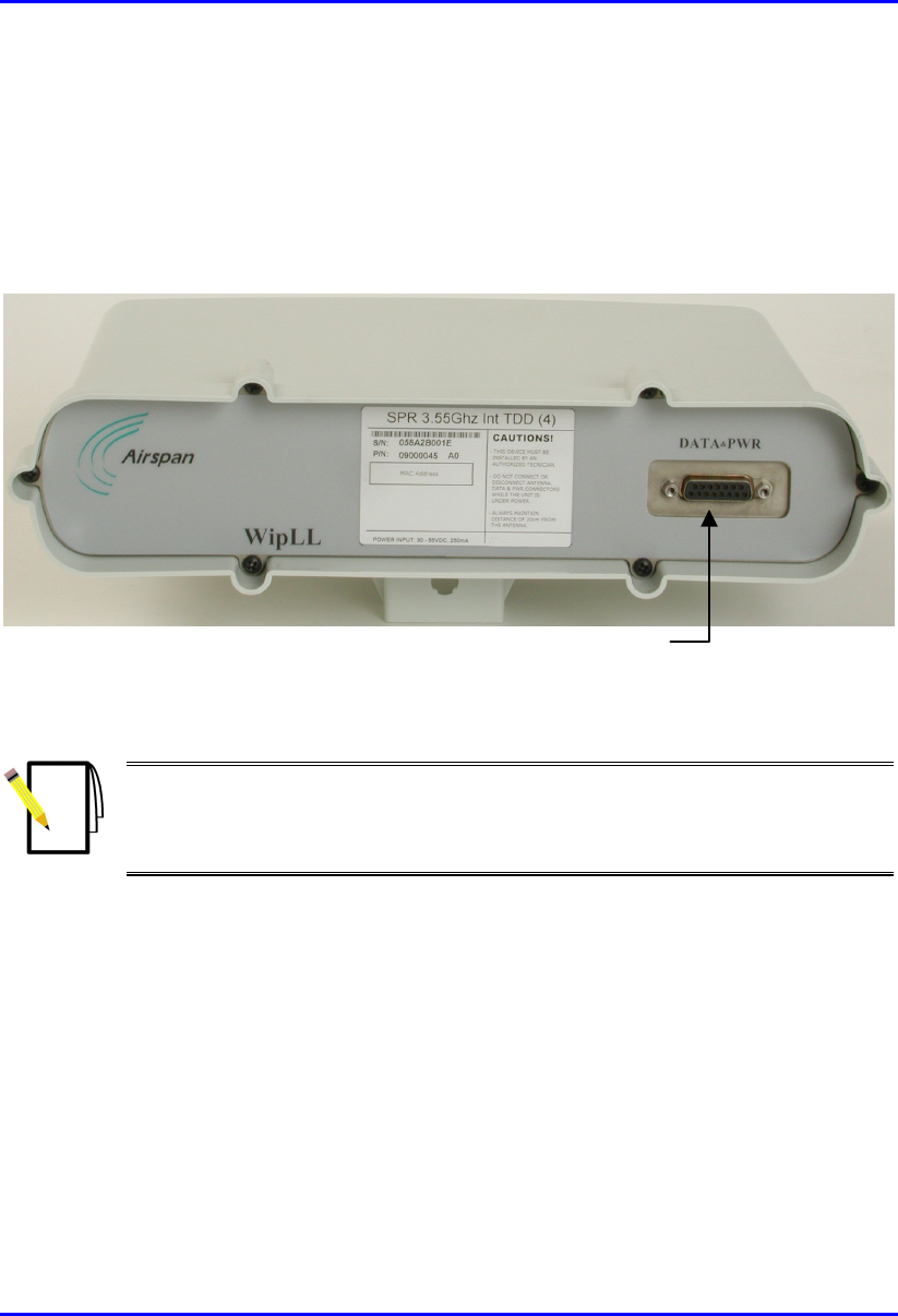
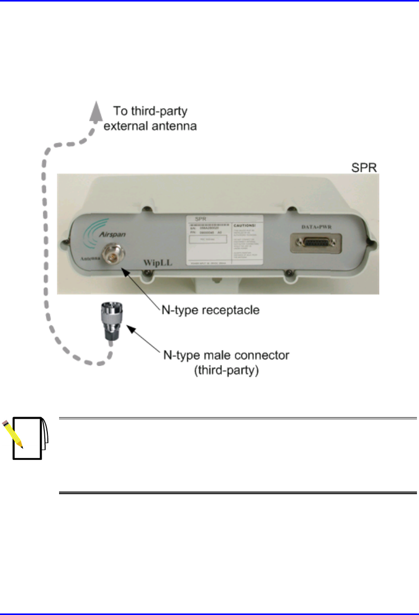
To connect the SPR to a third-party external antenna:
Connect an N-type male connector of the third-party antenna to the N-type port
located on the SPR’s front panel, as displayed in Figure 16-1.
Figure 16-1: SPR model with N-type connector for attaching an external antenna
Notes:
1) For crimping RF coaxial cables to N-type connectors, see Appendix C,
“Cable Crimping".
2) For a description of third-party antennas offered by Airspan for SPRs
operating in the 700 MHz band, see Appendix G, "Third-Party Antenna
Specifications.