Airspan Networks AIRSPAN-58 ASWipLL 5.8 GHz User Manual Section 2 Revised
Airspan Networks Inc ASWipLL 5.8 GHz Users Manual Section 2 Revised
Contents
- 1. User Manual A
- 2. User Manual B
- 3. Users Manual Section 2 Revised
Users Manual Section 2 Revised

Leading the World in Wireless DSL
ASWipLL and
ASWipLL and ASWipLL and
ASWipLL and
AS3010 Systems
AS3010 SystemsAS3010 Systems
AS3010 Systems
Wireless IP-Based Local Loop System
Release 4.6
Hardware Installation
Guide

The ASWipLL product bears the CE marking. This CE marking demonstrates ASWipLL's full compliance with
applicable European Union (EU) directives:
The ASWipLL product bears the Underwriters Laboratories (UL) marking, demonstrating full compliance with UL's
safety requirements:
ASWipLL products also bear the Federal Communications Commission (FCC) marking, demonstrating compliance
with FCC Part 15 regulations.
Revision Record: ASWipLL Hardware Installation Guide
Pub. Rev. Date Update Description
- Nov-00 First edition and printing. (Marconi)
- Mar-01 ASWipLL Release 1.4 (Marconi)
- Apr-01 ASWipLL Release 2.0 (Marconi)
- Jul-01 ASWipLL Release 2.2 (Marconi)
- Nov-01 ASWipLL Release 2.6 (Marconi)
- Jun-02 ASWipLL Release 3.0A (Marconi)
01 Feb-03 ASWipLL Release 4.0. Author: MD. Updates: Airspan template and content
(connector pinouts; cable crimping, and general)
02 May-03 ASWipLL Release 4.2F. Author: MD. Updates: graphics, deleted BSR with serial
port.
03 Jul-03 ASWipLL Release 4.2A. Author: MD. Updates: Chapter 1 for Transparent
Bridging; 5.8 GHz; 2.8 GHz.
04 Aug-03 ASWipLL Release 4.2A. Author: MD. Updates: formatting; graphics; BSDU
LEDs
05 Oct-03 ASWipLL & AS3010 Rel. 42B. Auth: MD. Updates: RSSI Plug for SPR; IDR
RSSI levels; SDA-4S/Vltag; safety guidelines; Append. D.
06 Feb-04 ASWipLL & AS3010 Rel. 4.4. Auth: MD. Updates: RSS LED plug photo
07 Aug-04 Rel. 4.6. Auth: MD. Updates: SDA-1/48V; SDA-1/DC; Link Quality; additional
FCC safety guidelines; Site Planning; miscellaneous.
Publication No. 02030311-07
02030311-07 Airspan Networks Inc. 2-1
Safety Guidelines
Safety GuidelinesSafety Guidelines
Safety Guidelines
This chapter outlines safety guidelines when installing the ASWipLL system.
Warning: The user and the installer should be aware that changes and
modifications not expressly approved by Airspan Networks could void the
user’s authority to operate the equipment.
Warning: Never install equipment that is damaged.
Warning: Only qualified personnel should be allowed to install, replace, and
service the ASWipLL equipment.
2
Safety Guidelines Hardware Installation Guide
2-2 Airspan Networks Inc. 02030311-07
2.1. ASWipLL Radios and Third-Party External
Antennas
Warning: Do not connect and disconnect antennas while the power is on. This
can cause irreversible device damage.
Warning: The digital portion of the transceiver has been tested and found to
comply with the limits for a Class B digital device, pursuant to part 15 of the
FCC rules. These limits are designed to provide reasonable protection against
harmful interference in a residential installation. This equipment generates,
uses, and can radiate radio frequency energy and, if not installed and used in
accordance with the instructions, may cause harmful interference to radio
communications. However, there is no guarantee that interference will not
occur in a particular installation. If this equipment does cause harmful
interference to radio or television reception, which can be determined by
turning the equipment on and off, the user is encouraged to try correct the
interference by performing one or more of the following measures:
- Reorientate or relocate the receiving antenna
- Increase separation between the equipment and receiver
- Connect the equipment to an outlet on a circuit different from that to which
the receiver is connected
- Consult the dealer or an experienced radio/TV technician for help
Warnings:
1) The device cannot be sold retail, to the general public or by mail order. It
must be sold to dealers.
2) Installation must be controlled.
3) Installation must be performed by licensed professionals.
4) Installation requires special training.
Warning: The ASWipLL radio devices and antennas should be installed
ONLY by experienced installation professionals who are familiar with local
building and safety codes and, wherever applicable, are licensed by the
appropriate government regulatory authorities. Failure to do so may void
A
irspan’s ASWipLL product warranty and may expose the end user or the
service provider to legal and financial liabilities. Airspan and its resellers o
r
distributors are not liable for injury, damage or violation of regulations
associated with the installation of outdoor units or antennas.
Hardware Installation Guide Safety Guidelines
02030311-07 Airspan Networks Inc. 2-3
Warning: For unlicensed bands, it is the responsibility of the person installing
the ASWipLL system to ensure that when using the outdoor antenna kits in the
United States (or where FCC rules apply), that only those antennas certified
with the product are used. The use of any antenna other than those certified
with the product is expressly forbidden in accordance with FCC rules CFR47
part 15.204. The installer should configure the output power level of antennas
according to country regulations and per antenna type.
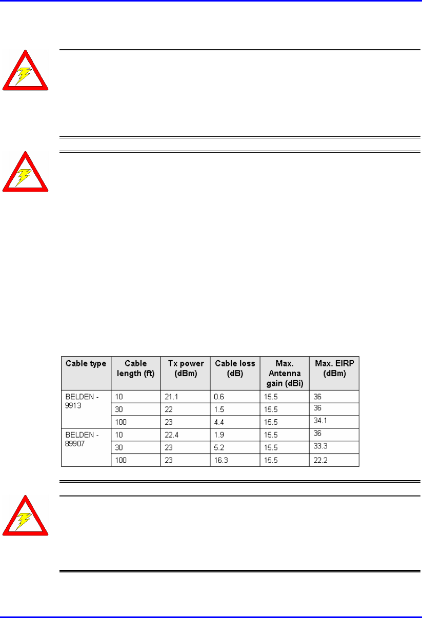
Warning: For unlicensed bands, in accordance with FCC regulations, ensure
that the external antennas provide an EIRP of less than or equal to 36 dBm to
prevent interference with other radios operating in the unlicensed band. The
EIRP is defined by the following formula:
Max. Power Output + Antenna Gain - Cable Loss ≤ 36 dBm (EIRP)
Airspan does not supply cables for connecting external antennas. It is the
responsibility of the installer to provide the cable and ensure cable
characteristics (e.g. length and cable loss) enables adherence to FCC's
regulations concerning maximum EIRP. When calculating output power based
on cable loss, always assume the ASWipLL radio is configured for maximum
rate mode (i.e. 1.33/4 Mbps), which provides greater Tx power than low rate
modes (1/2/3 Mbps). For example, for 5.8 GHz, always assume max. Tx power
at SPR's antenna connector as 21 dBm.
The table below lists examples of cable loss per cable (not supplied by
Airspan) for maximum antenna gains, based on the formula above. Note that
the EIRP is either equal to or less than 36 dBm.
Warning: The ASWipLL transceivers emit microwave radiation. Therefore, a
minimum distance must be maintained from the front of the ASWipLL radios:
- Unlicensed bands (e.g. 5.8 GHz): 200 mm
- Licensed bands:
- 700 MHz (i.e. ASWipLL 700) = 800 mm
- 2.5 GHz (i.e. ASWipLL 2.5) = 500 mm
Safety Guidelines Hardware Installation Guide
2-4 Airspan Networks Inc. 02030311-07
Warning: To avoid RF interference between BSRs operating in the 700 MHz
where four BSRs are installed at a Base Station, a 1-meter separation must be
provided between the BSRs' antennas operating in the lower frequencies (i.e.
711.5 and 714.5 for 1 Msps mode; 712 and 714 for 1.33 Msps mode) and the
BSRs' antennas operating in the upper frequencies (i.e. 741.5 and 744.5 for 1
Msps mode; 742 and 744 for 1.33 Msps mode).
Warning: When using external antennas, the external antennas must not be
co-located or operating in conjunction with any other antenna or transmitter.
Warning: ASWipLL radios using an external antenna(s) must not be co-
located or operating in conjunction with any other antenna or transmitter.
Warning: Inherent risks exist in operating equipment in license-exempt bands
(i.e. 900 MHz). Airspan recommends that you do not purchase or deploy any
equipment that operates in license-exempt bands without first analyzing the
interference environment at each of your proposed deployment locations.
Please contact your Authorized Airspan System Integrator or Distributor if you
have any questions or require assistance regarding interference analysis.
Airspan Networks will not be held responsible for product performance issues
related to interference.
Warning: In environments that produce disturbances such as paging systems,
Airspan recommends using a narrow-band cavity filter and implementing the
appropriate frequency bands (within the filter's capabilities), i.e. building an
NVRAM frequency table using only these frequencies.
Warning: Mount outdoor radios so that their front panel ports face down to
prevent water from settling on the ports. This avoids damage to the units such
as corrosion and electrical short-circuiting.
Warning: Do not mount outdoor radios and external antennas in weathe
r
such as rain or lightening that may increase risk of electrocution.
Hardware Installation Guide Safety Guidelines
02030311-07 Airspan Networks Inc. 2-5
2.2. Electrical Safety Guidelines
Warning: Connect the power only after all network and antenna cable
connections are performed. Powering the device before connecting, fo
r
example, the external antenna, can lead to irreversible device damage.
Warning: To prevent short-circuiting and electrical shocks, cables with
exposed ends (i.e. not yet crimped) should be covered with protective
polythene bags during external cable installation processes.
2.2.1. Handling Electrostatic Devices
Warning: To prevent ESD damage to ASWipLL devices, always wear an ESD
wrist strap when handling these devices or coming into contact with internal
components.
Electrostatic devices are those devices that may be damaged by the inadvertent
discharge of static electricity from a charged body. The risk of damage, due to
electrostatic discharge (ESD) to a device, may cause the device to fail suddenly, or it
may induce a partial defect within the device, which will cause subsequent
premature failure. Static electricity can result from operators walking on floors,
moving around on chairs, from the movement of operator's clothing or even casual
brushing against racks, benches or walls.
Airspan recommends the following guidelines to be adopted to minimize the risk of
component failure due to electrostatic discharge to the device:
! ASWipLL devices are provided typically in see-through anti-static bags.
Wherever possible, checking and inspection of a unit should occur without
removing it from the bag.
! All operators shall wear the approved conductive overall.
! Where operators come into direct contact with any piece of electronic hardware,
operators must wear an ESD-preventive wrist strap. All straps and cords
should be tested using a Wrist Strap Tester prior to use. The wrist strap cords
shall have a 2 Meg Ohm resistor fitted at either end. Wrist straps should be worn
in direct contact with bare skin and not over clothing.
Safety Guidelines Hardware Installation Guide
2-6 Airspan Networks Inc. 02030311-07
2.2.2. Grounding
Only certain ASWipLL devices require additional grounding. ASWipLL devices
that do not require additional grounding have grounding at the main supply outlet.
The following table lists the ASWipLL devices’ grounding requirements.
Table 2-1: ASWipLL grounding requirements
Site ASWipLL device Grounding
BSR Through the mains (via BSDU) i.e. no additional
grounding required
BSDU Additional grounding required (grounding lug at rear
end of chassis)
Base Station
BSPS Additional grounding required (grounding lug at rear
end of chassis)
SPR Through the mains (via SDA), i.e. no additional
grounding required
CPE
IDR Through the mains, i.e. no additional grounding
required
2.2.3. Lightening Protection
Warning: Never install the equipment during stormy weather and lightening.
ASWipLL devices comply with the Surge Immunity standard: EN 61000-4-5.
ASWipLL devices are protected from lightening surges as the outdoor devices
(BSRs and SPRs) are encased in a plastic chassis. Therefore, if lightening strikes the
device, an electrical circuit cannot be completed, and hence, no electrical surge can
occur.
In addition, ASWipLL outdoor and indoor (SDA) devices provide high-speed data
line protection against direct and induced transient over-voltages surges on the
cables. This capability is provided by the fact that all ASWipLL devices are
designed with TVS (transient voltage suppressor) components that maintain
potential differences.
Hardware Installation Guide Safety Guidelines
02030311-07 Airspan Networks Inc. 2-7
However, for geographical areas that have above normal lightening activity, Airspan
can supply a surge protector composed of a 15-pin D-type adapter with a grounding
wire.
2.3. Cabling
Warning: The maximum cable length between the radio transmitters (i.e. BSR
and SPR) and terminating equipment is 100 meters.
Warning: Cables with exposed ends (i.e. not yet crimped) should be covered
with protective polythene bags during external cable installation processes.
Warning: Prior to the commencement of any installation, commissioning work
at ‘live’ sites it is the responsibility of the Airspan engineer to advise the
customers representative before any activity commences. If in doubt assume
equipment is ‘live’.
Warning: Disturbance of cables on an In-Service exchange can cause loss o
f
service. Extreme care must be taken when installing cables at any customer o
r
subscriber premises.
2.3.1. Considerations
The following issues should be considered during cabling at the ASWipLL Base
Station and customer premises:
! Cable routes are to be defined in the site-specific documentation.
Note: A minimum separation of 200 mm should exist between power and data
cables. However, it is permissible to allow these cables to cross each other at
right angles.
! Observe recommended minimum bend radii when installing copper cables.
Wherever a cable changes direction, ensure that it does so in a smooth curve
with a radius of at least 50 mm to prevent damage.

Safety Guidelines Hardware Installation Guide
2-8 Airspan Networks Inc. 02030311-07
! Plastic ties and wraps are to be used to secure cables at regular intervals to trays,
guides, and mounting pole/bracket. Ensure all trimmed ends are disposed of
safely and at regular intervals.
! Data cables of less than 20 pairs shall be mixed in bundles not exceeding 50 mm
in diameter.
! Ensure cables are not trapped in cabinet doors, by slide-in equipment or support
metalwork.
! Excessive stress on cable terminations caused by taught cables should be
avoided. Connector strain relief, if not built into the connector used, shall be
provided by means of a strategically located cable tie. A maintenance loop or a
generous amount of cable slack shall be provided just before the cable reaches
the ASWipLL device to allow for equipment removal without disturbance to
adjacent cables.
! When installing network cables, ensure they are not damaged by friction or sharp
edges.
! Data cables providing connection to the customers network shall be run in
protective conduits. Cable conduits should be secured to the wall in accordance
with manufacturers instructions.
! External data cables are to be protected in metal conduits, which are to be
secured to the building structure in accordance with manufacturers
recommendations.
! Wiring conduits must be placed in areas to prevent a trip hazard (e.g. don’t
install on roof walkways)
! Cables should be carefully fed through conduits and not pulled by means of any
attached connector.
! Sufficient space should be provided in cable conduits, trunking or trays (where
possible) to allow for future cabling growth.
! Data cables threaded into holes drilled in walls are to be covered by a waterproof
sheath to prevent water penetration.
Hardware Installation Guide Safety Guidelines
02030311-07 Airspan Networks Inc. 2-9
! Silicone sealant should be used to plug any holes on both internal and external
wall surfaces once cables are in place.
! Cables not housed in conduits must be placed in a manner to avoid a trip hazard.
(Avoid trailing wires across passageways.)
2.3.2. Labeling
The following labels are required to be fitted to ASWipLL equipment:
! Voltage Warning
! High Earth Leakage Current
! Signal Cable Designation
2.3.2.1. Voltage Warning
Warning: Voltages over 30 Volts AC and 50 Volts DC are categorized as
hazardous. Hazard warning labels should be fitted where required. Certain
countries require equipment warning and instruction labels to appear in the
local language. When installing ASWipLL equipment ensure that local
requirements regarding labels are given consideration.
! Where mains power is fed from separate phases, appropriate warning labels must
be fitted to warn of the increased danger.
! The AC equipment used in the BSPS cabinet must carry a relevant voltage
warning label specific to the country in which it is being installed. The label will
be fitted to the cabinet doors displaying an electrical hazard symbol, the local
operating voltage and the letters ‘AC’.
! A power feed identification label (e.g. PWR ‘A’) shall be applied in the
following locations:
! On the rear of the main power rack adjacent to the terminal block
! Attached to BSPS AC mains power plug or lead
! Attached to the customer mains power socket or distribution rail
! On the BSPS power circuit connection at the fuse board
Safety Guidelines Hardware Installation Guide
2-10 Airspan Networks Inc. 02030311-07
2.3.2.2. High Earth Leakage Current
If equipment earth leakage current exceeds 3.5 mA, a warning label as shown in
Figure 2-1 must be fitted to the rear of the main power rack alongside the AC inlet
terminal block.
Figure 2-1: Warning label if earth leakage current exceeds 3.5 mA
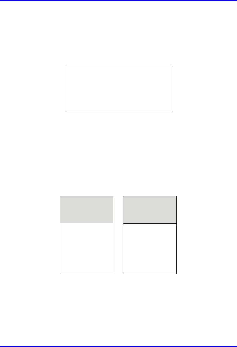
2.3.2.3. Signal Cable Designation
All data cables should be labeled with both the source and destination at each end. A
wrap around identification label, similar to that shown in Figure 2-2, is to be fitted to
both ends of ASWipLL data cables. Care should be taken to ensure that the cable
identification information is clearly visible. Fit the label 100 mm from the cable end.
Wrap the label ensuring good adhesion to cable and itself.
From
BDSU 1/1
To
SPR 1
To
SPR 1
From
BDSU 1/1
BSDU End SPR End
Figure 2-2: Typical signal cable identification label
WARNING
HIGH LEAKAGE CURRENT
Earth connection essential
Before connecting supply