Airspan Networks AIRSPAN-BSR Base Station Radio User Manual Revised
Airspan Networks Inc Base Station Radio Users Manual Revised
UserManual.wiki
>
Airspan Networks
>
AIRSPAN BSR User Manual
Users Manual Revised
Navigation menu
Upload a User Manual
Namespaces
Wiki Guide
HTML
PDF
Info
Views
User Manual
Discussion / Help
Navigation

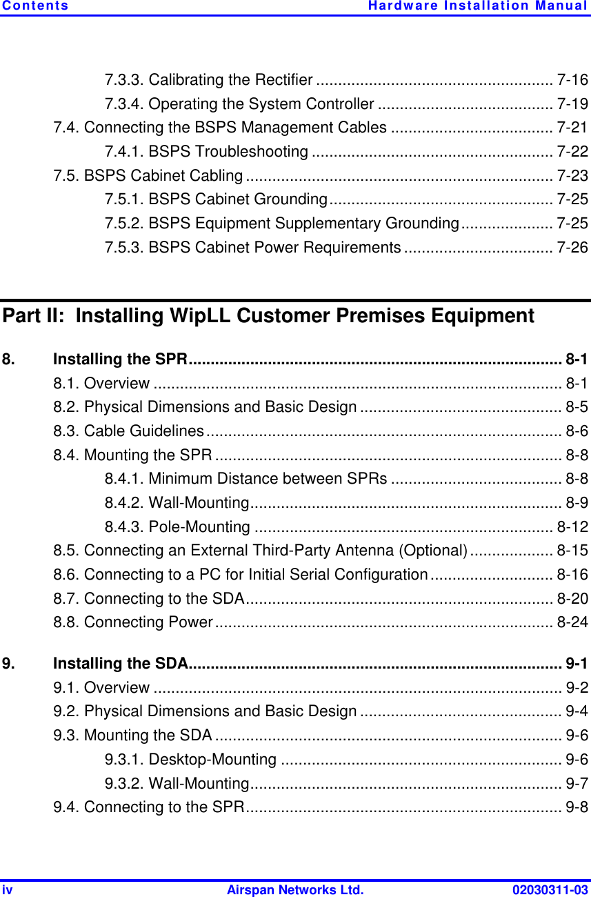

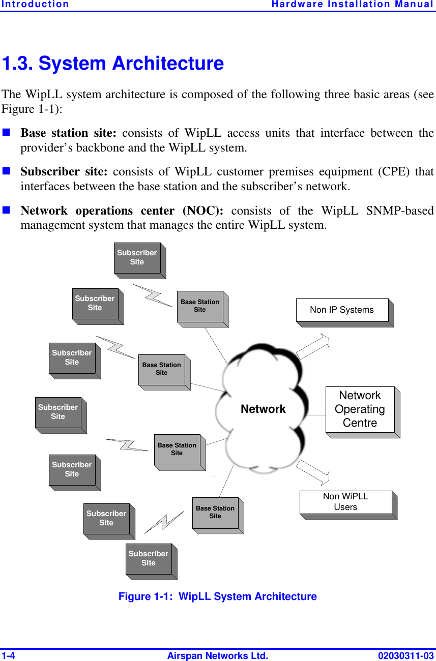
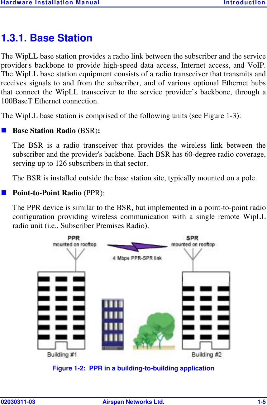
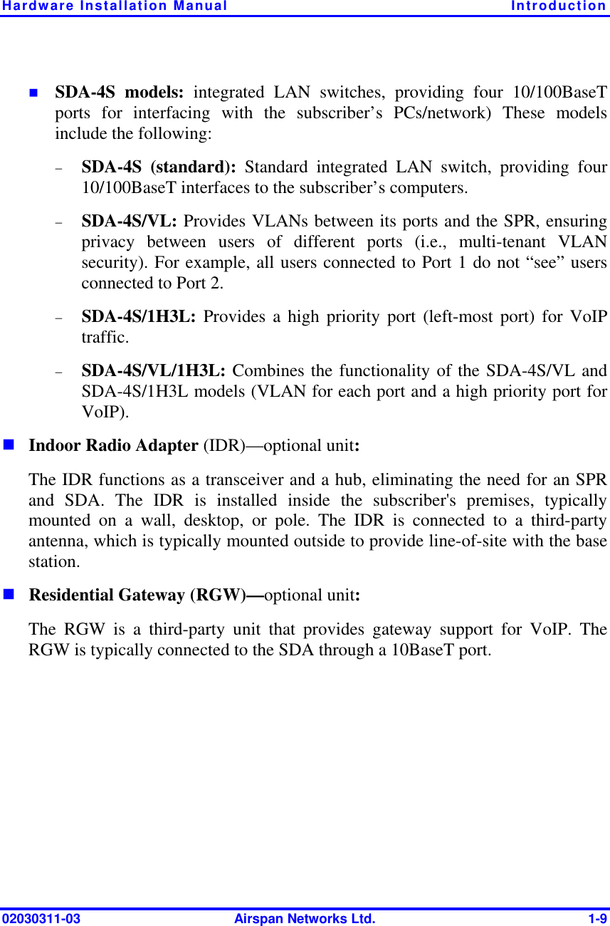

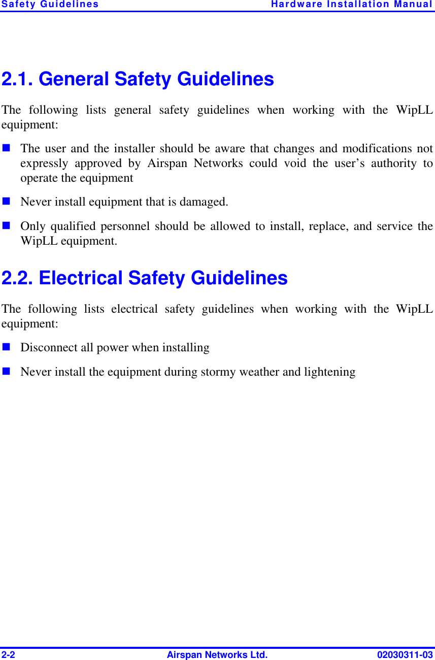
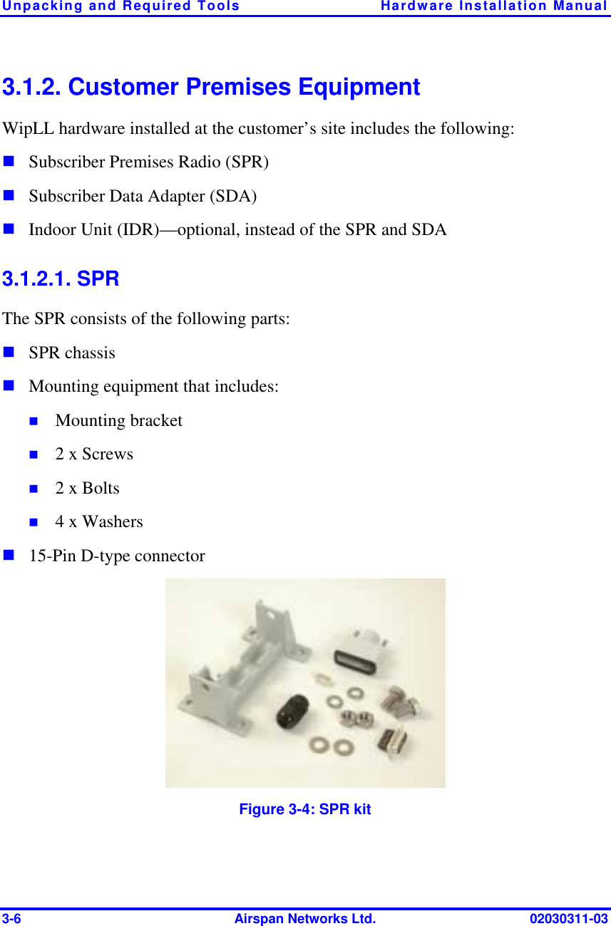
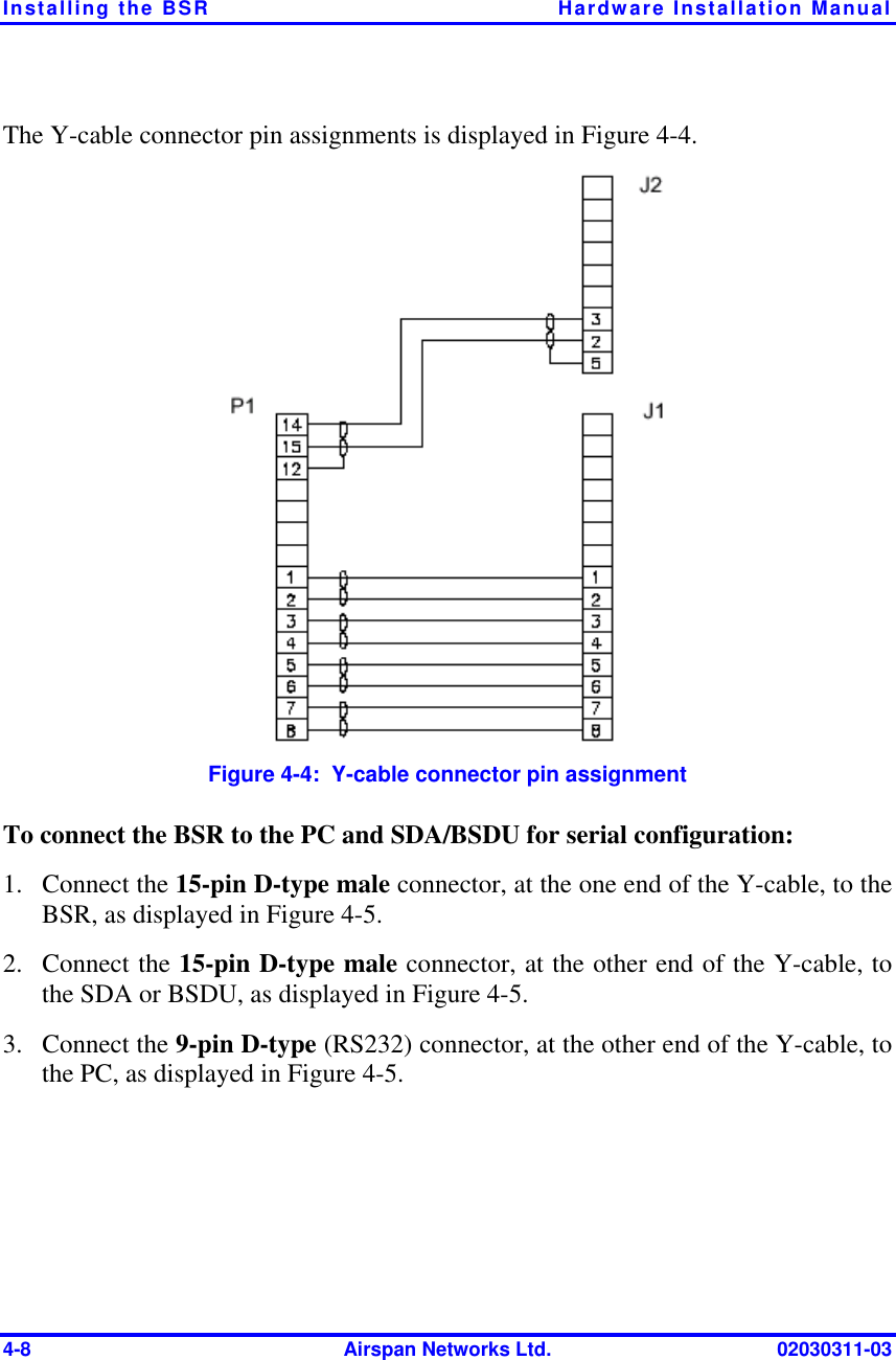
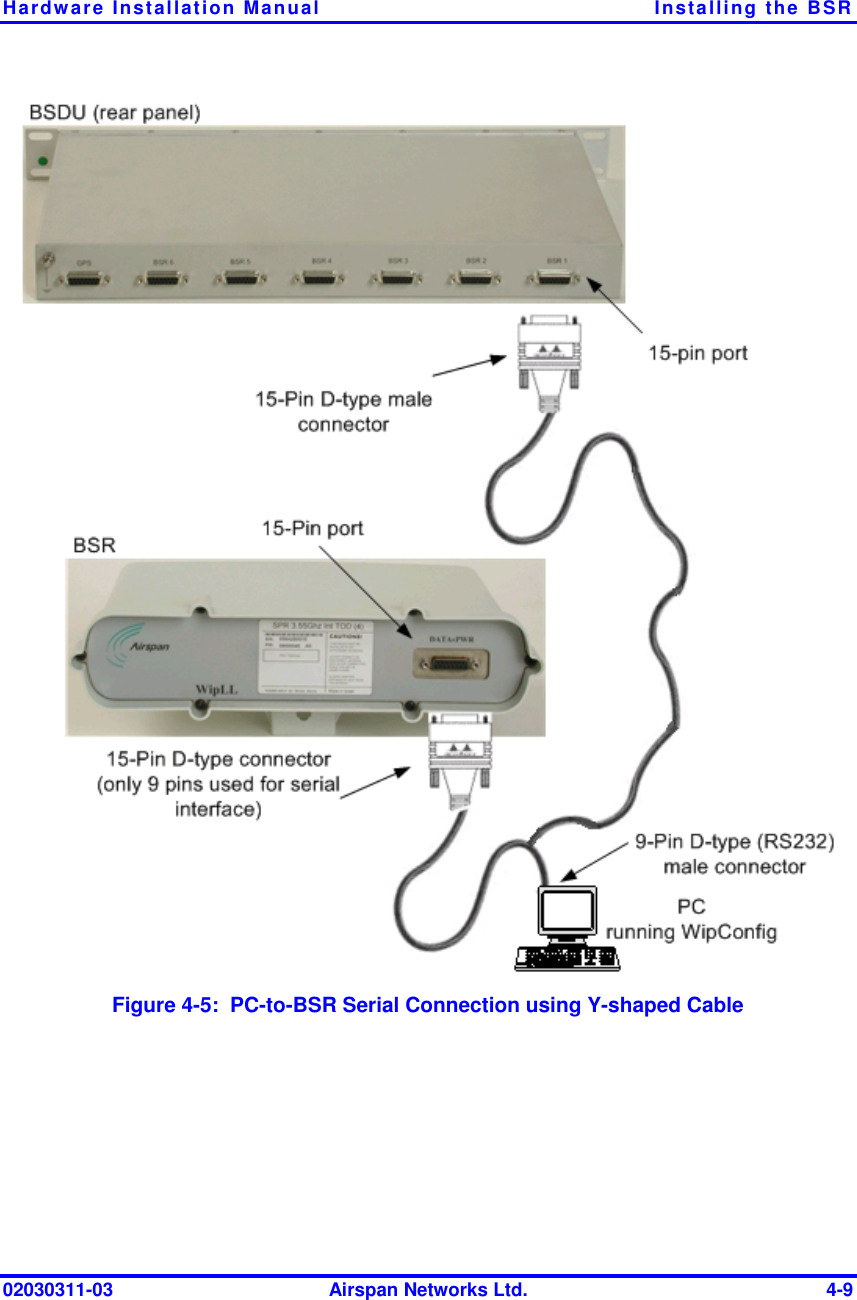
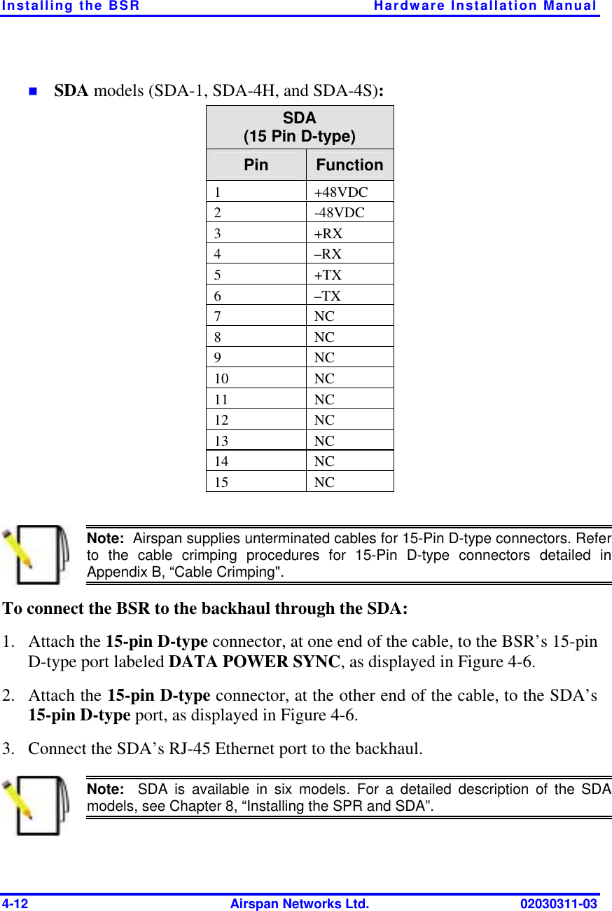
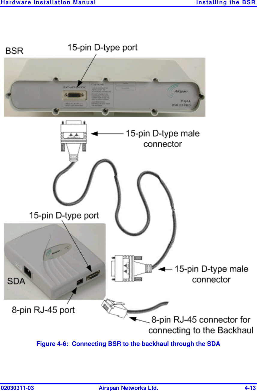
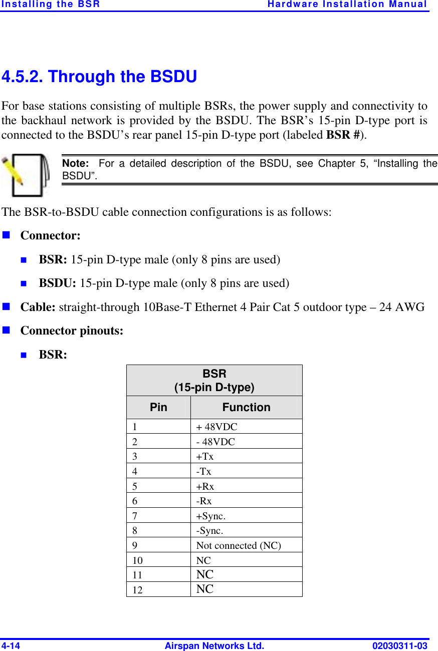
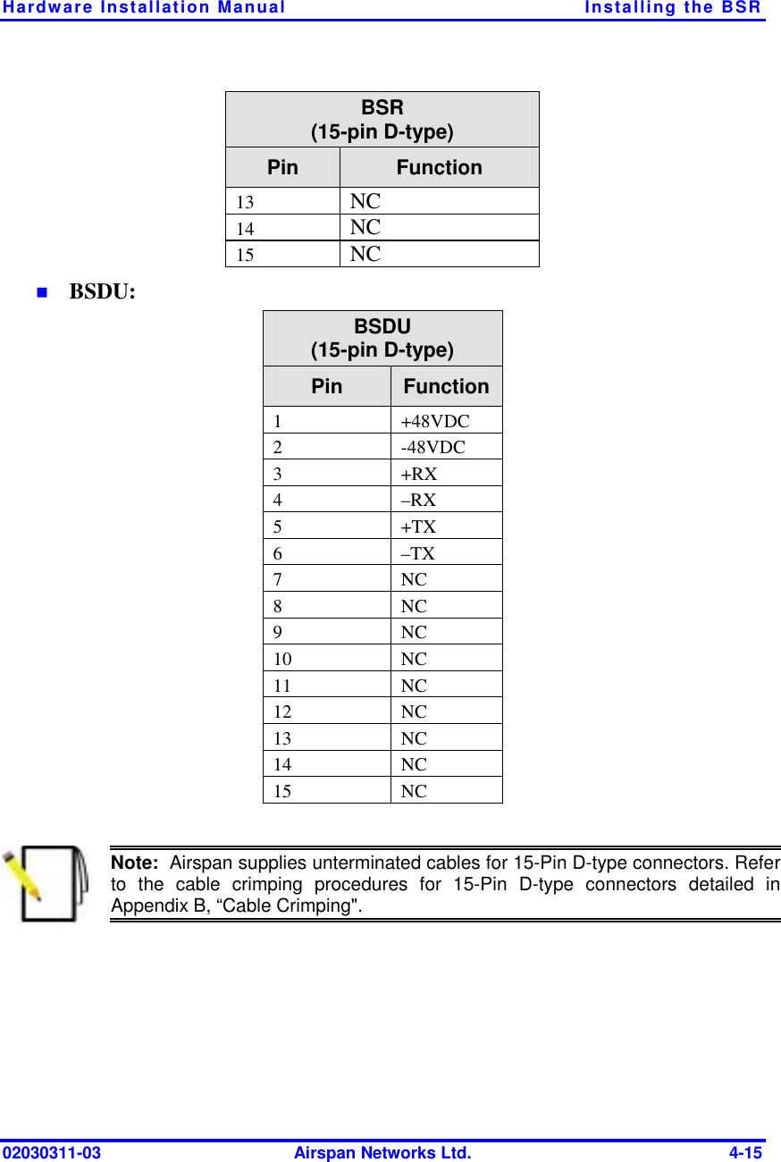
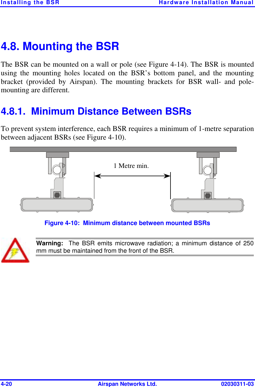
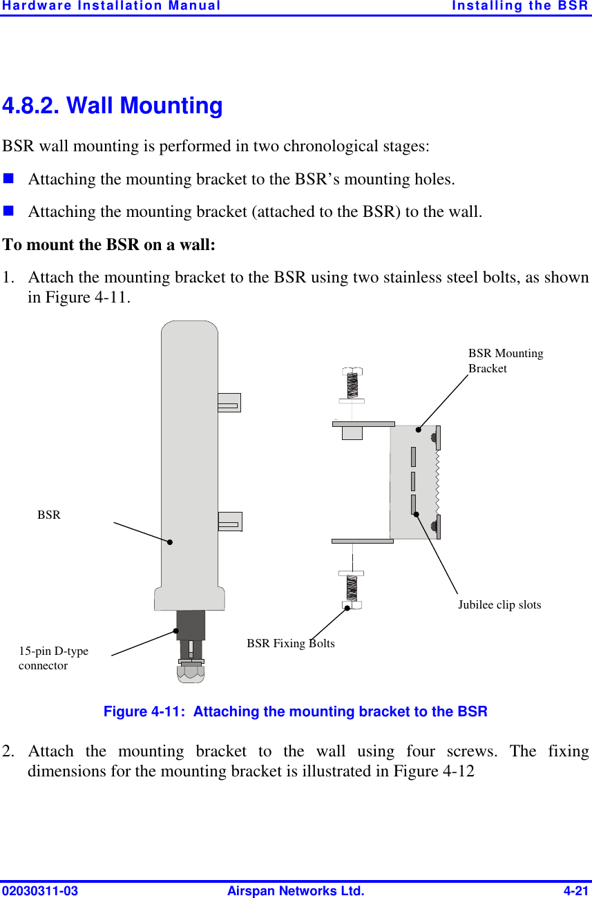
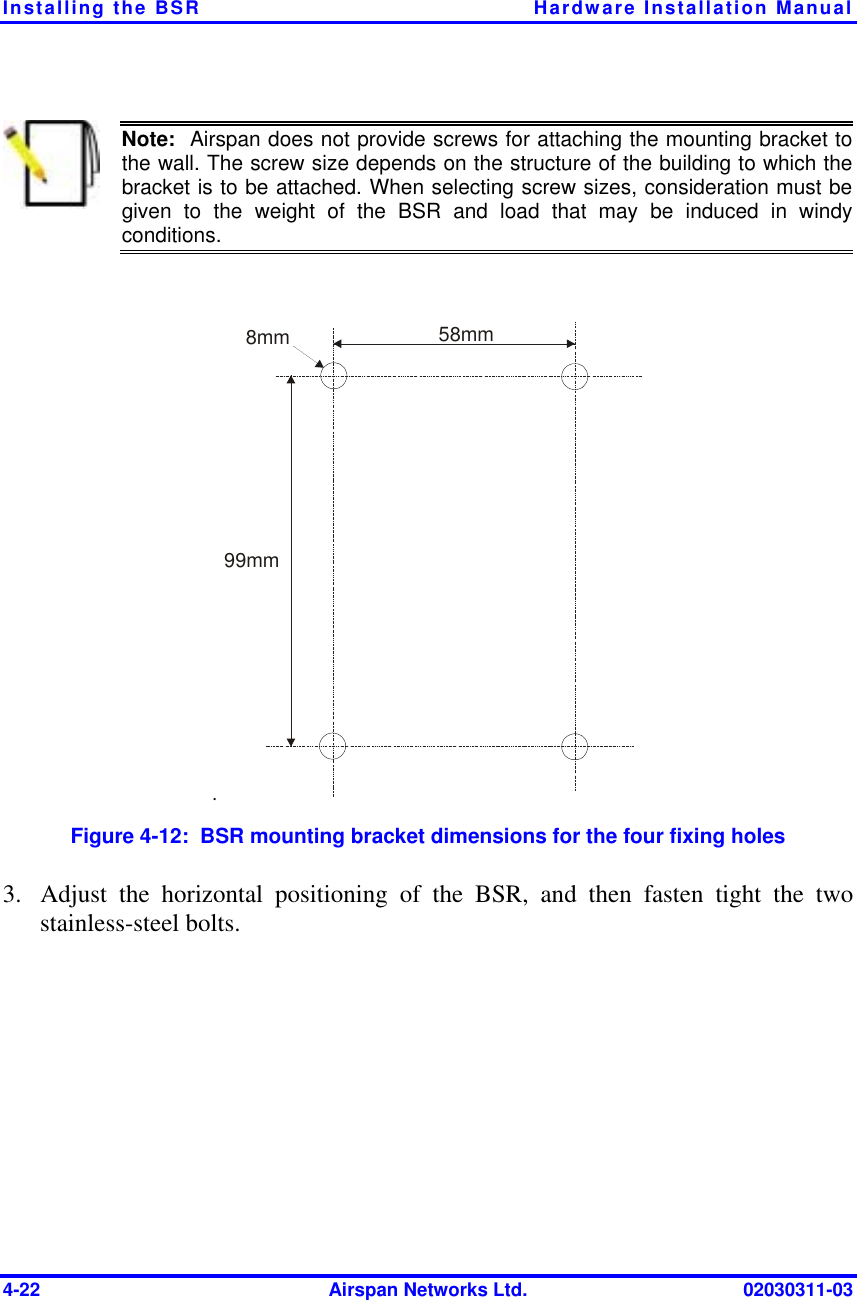
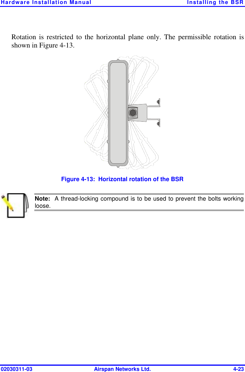
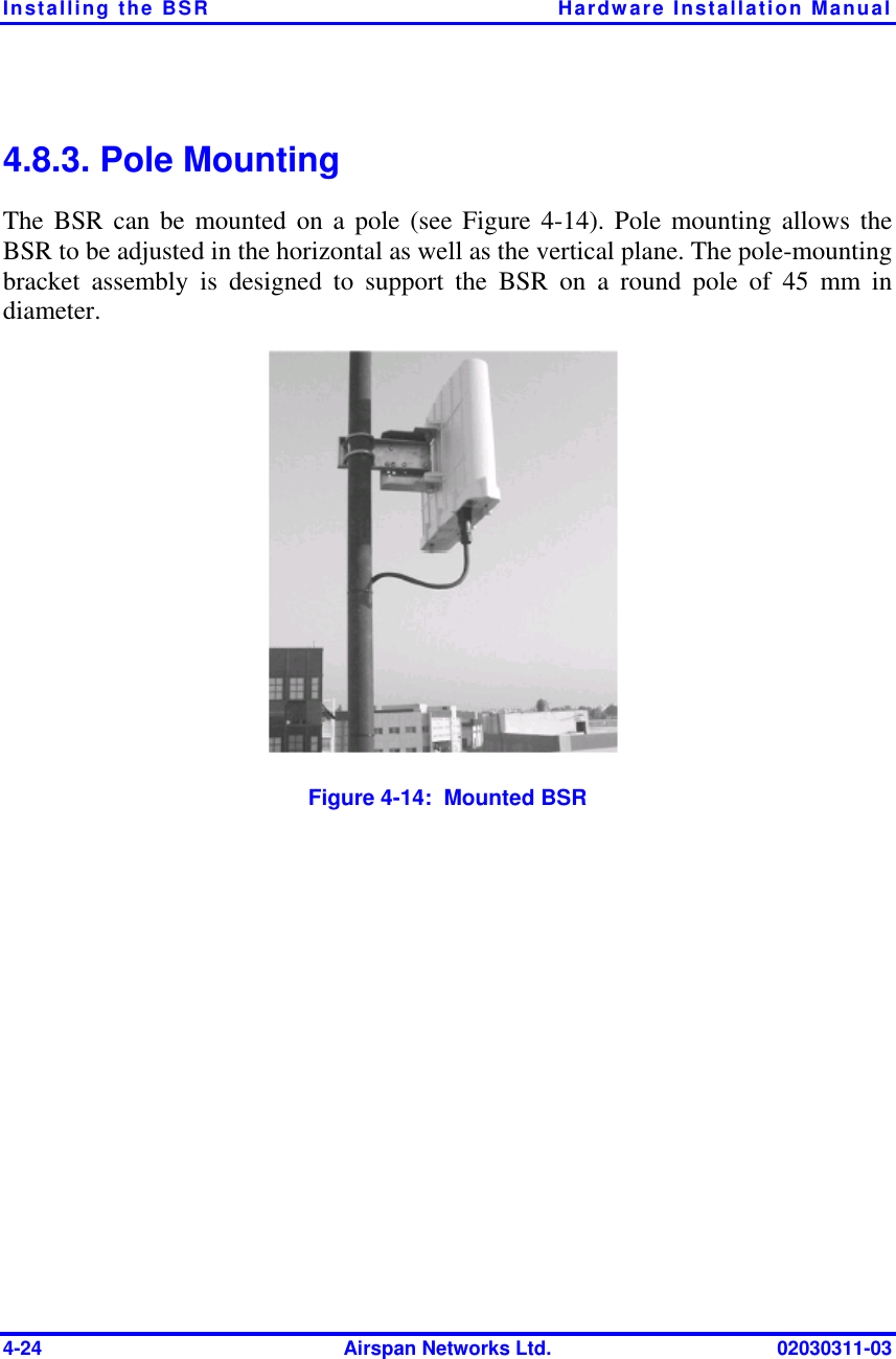
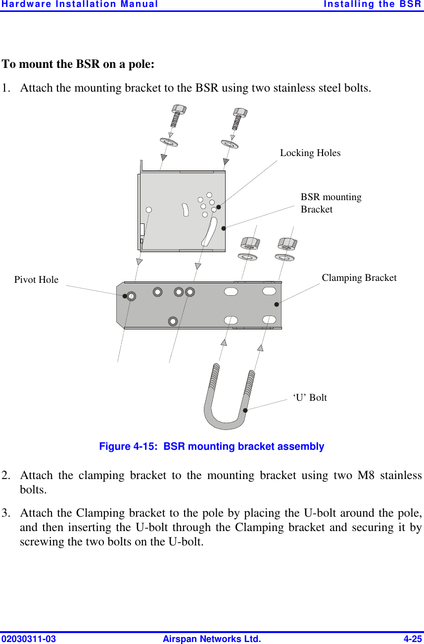
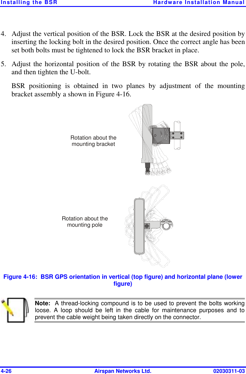
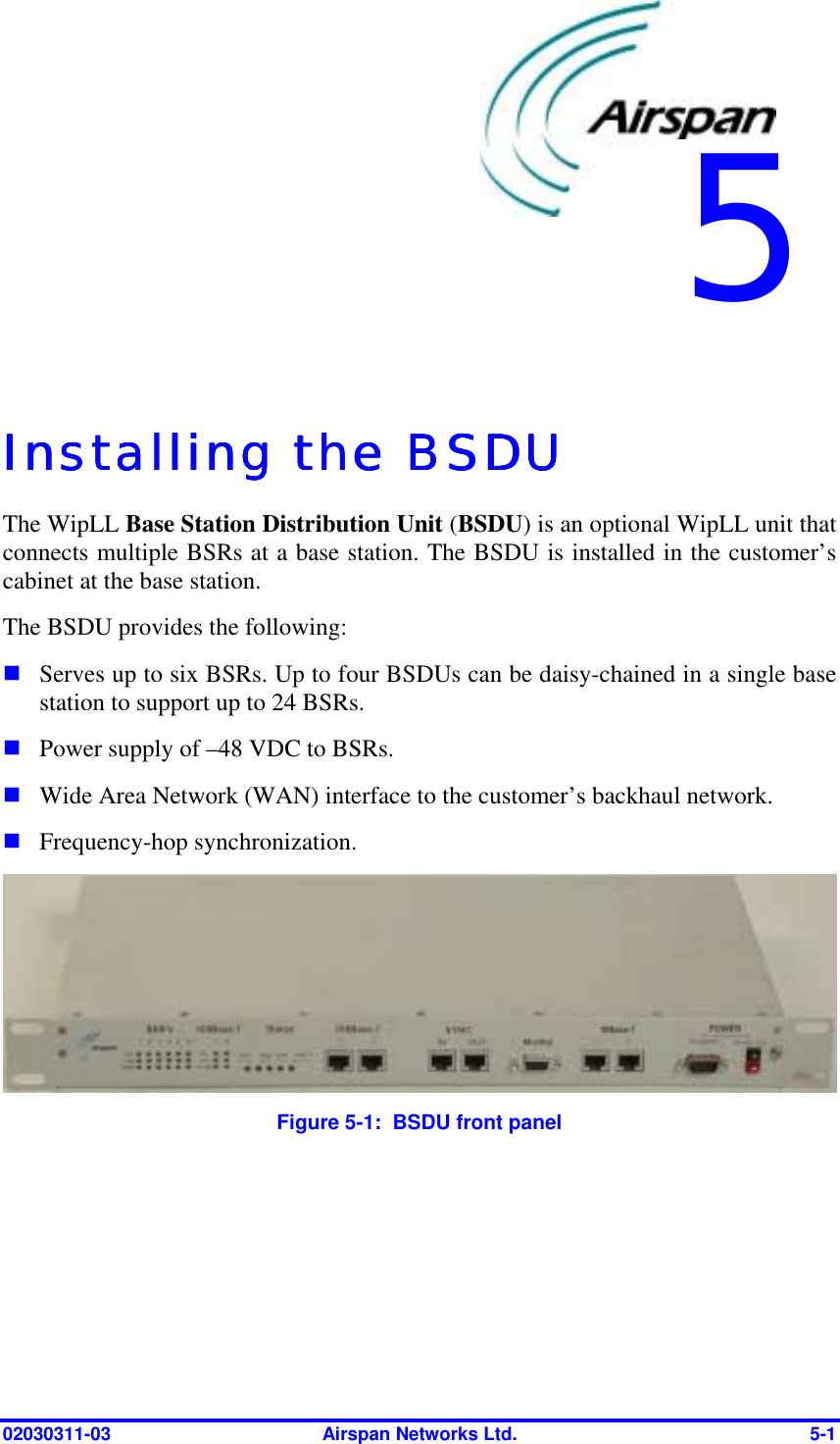
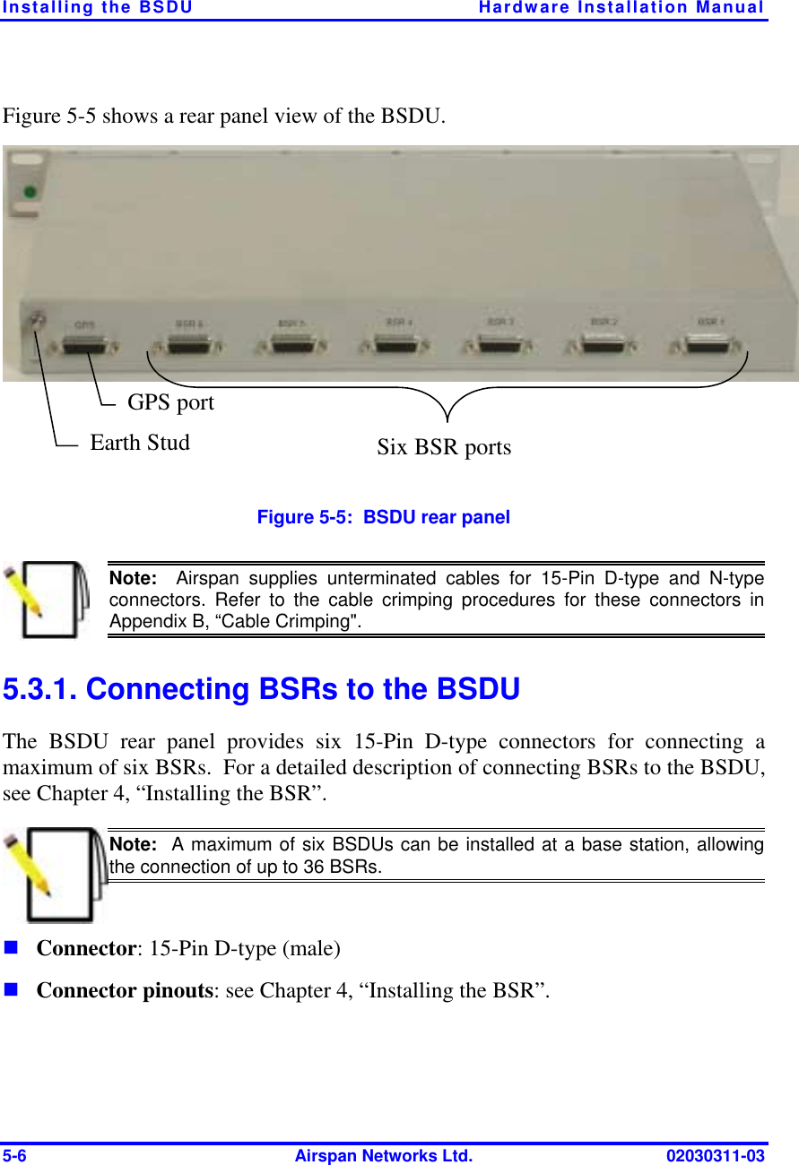
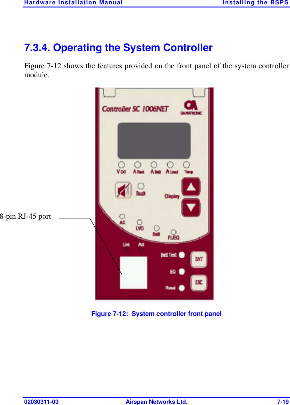
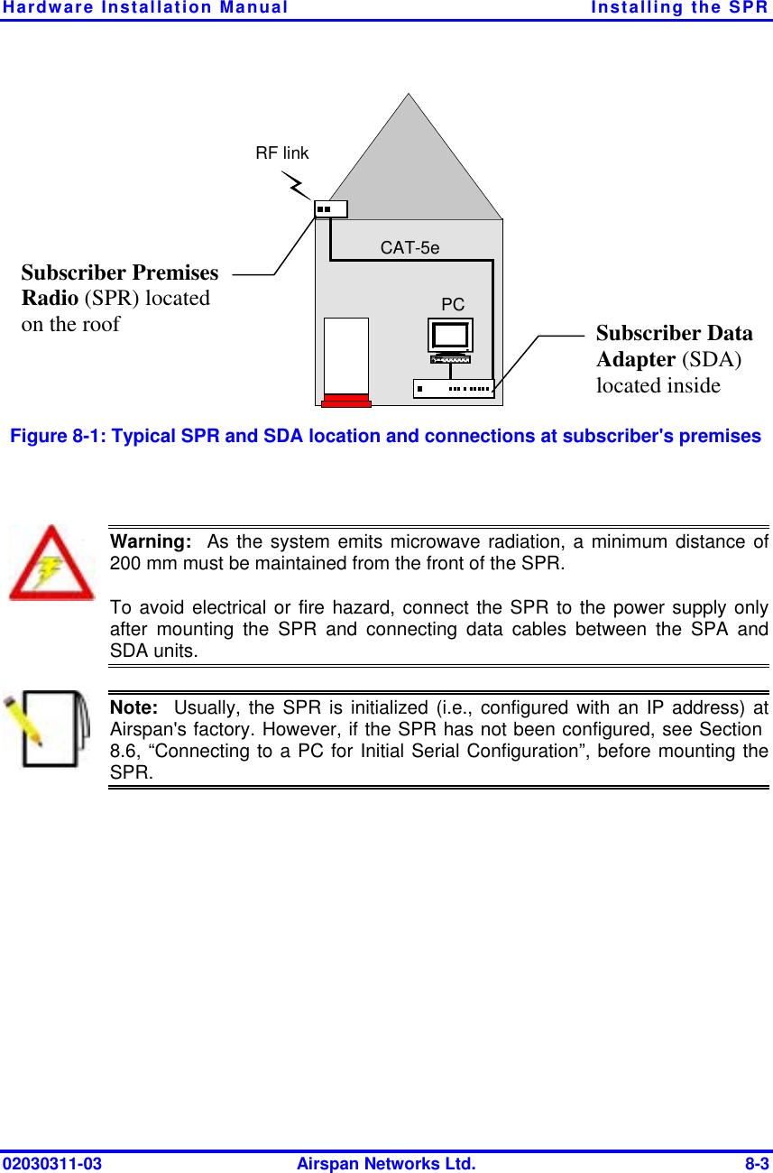
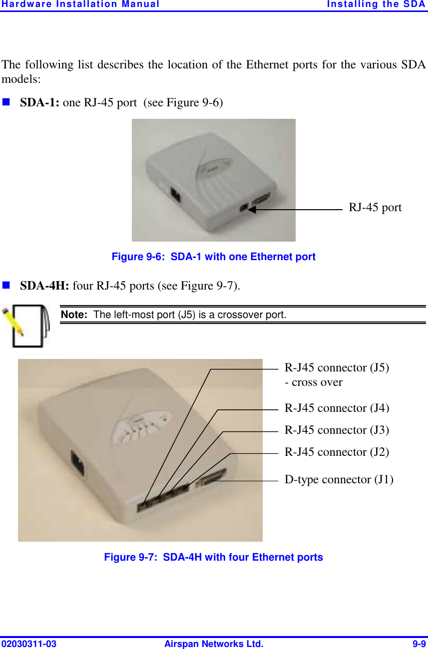
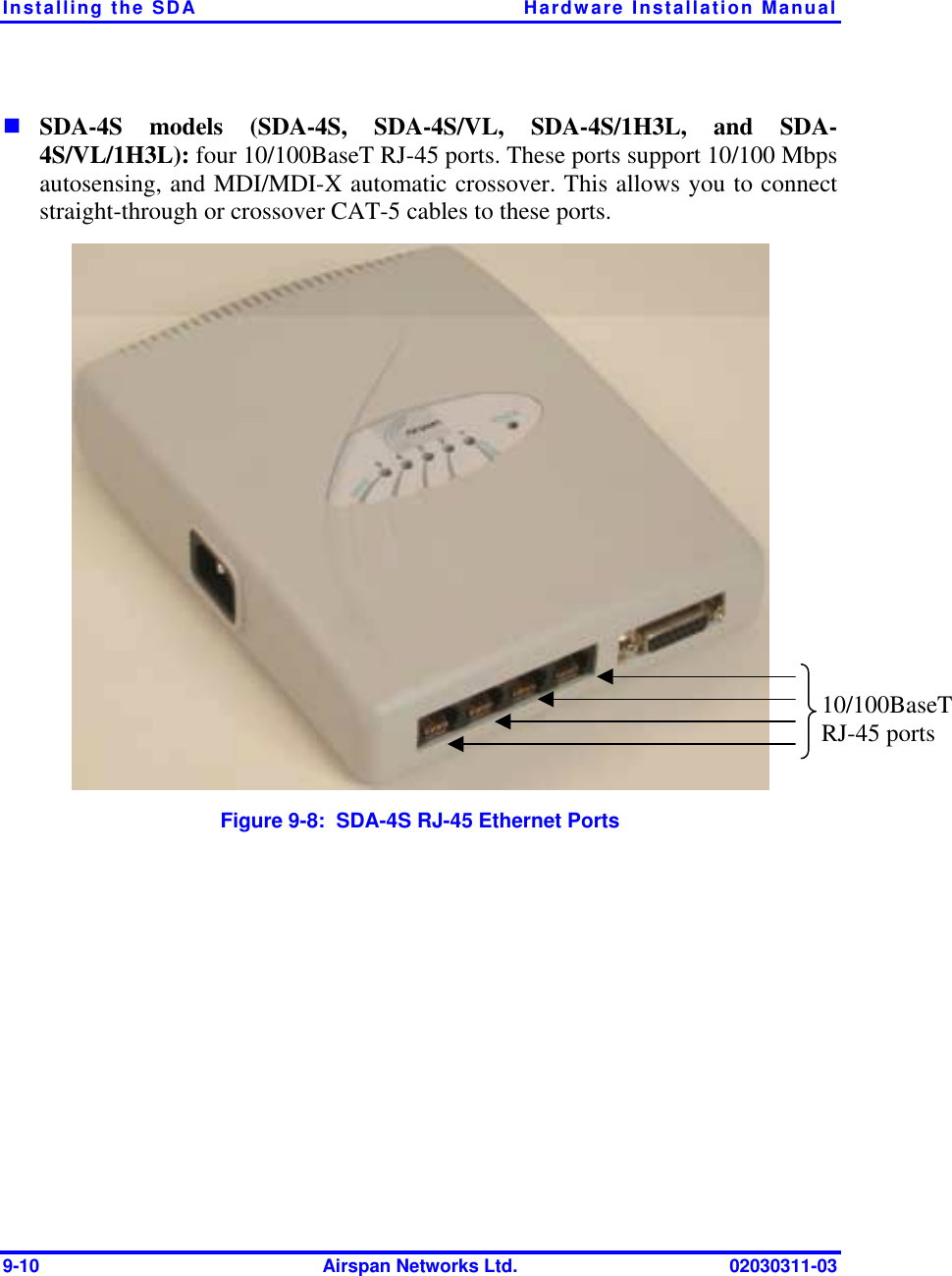
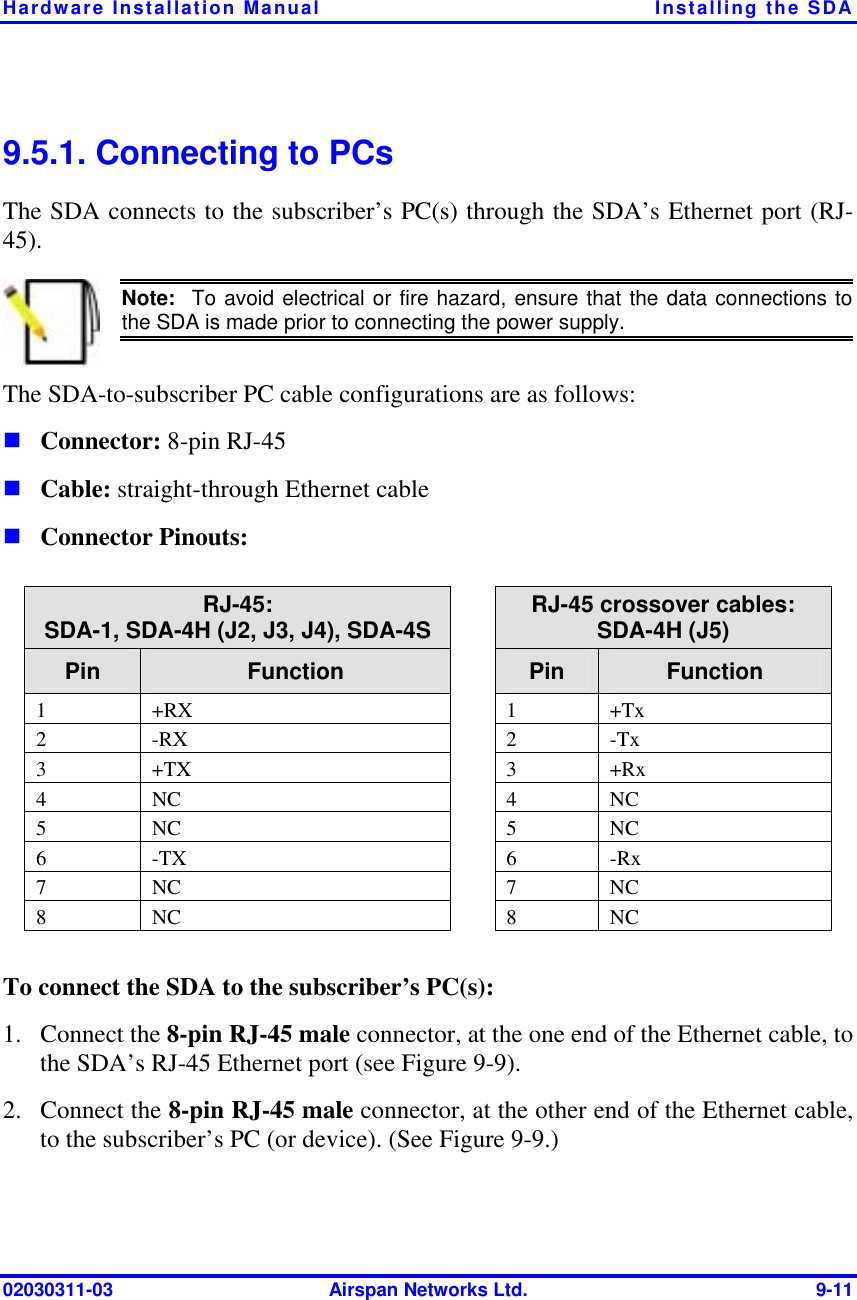
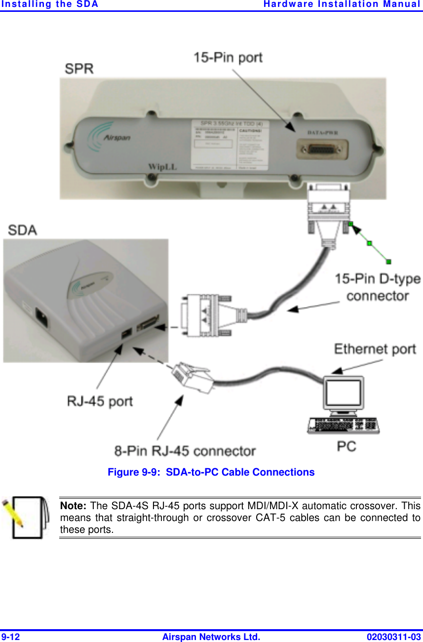
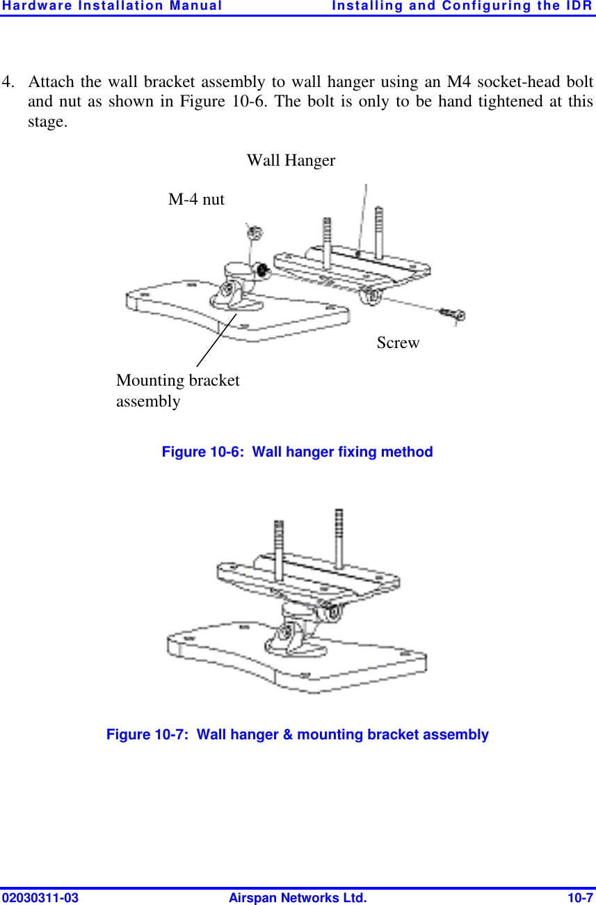
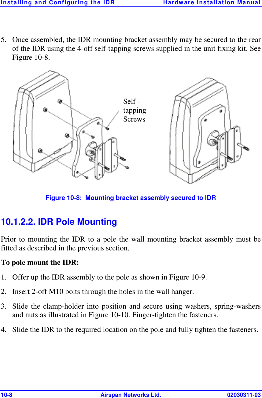
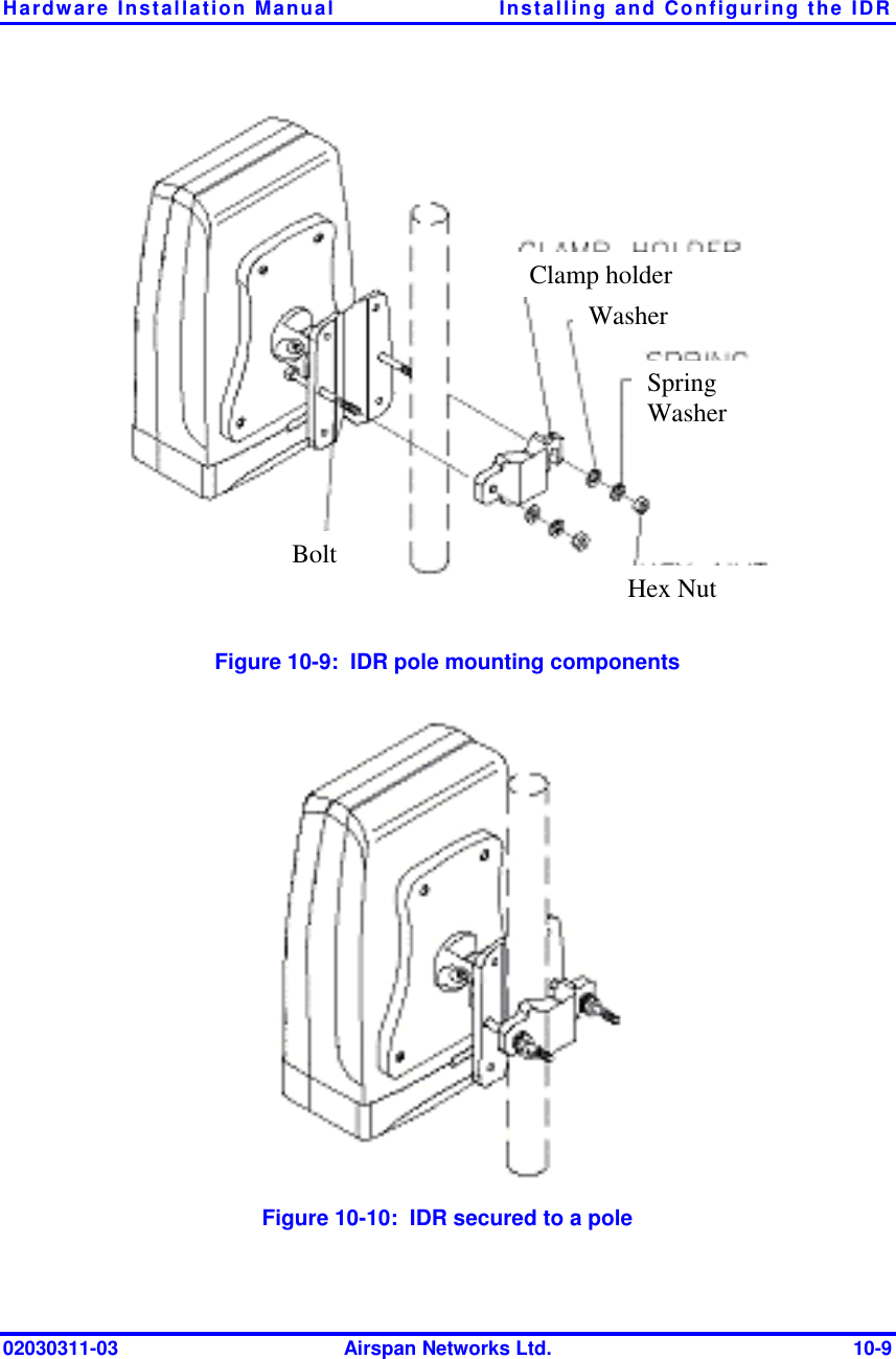
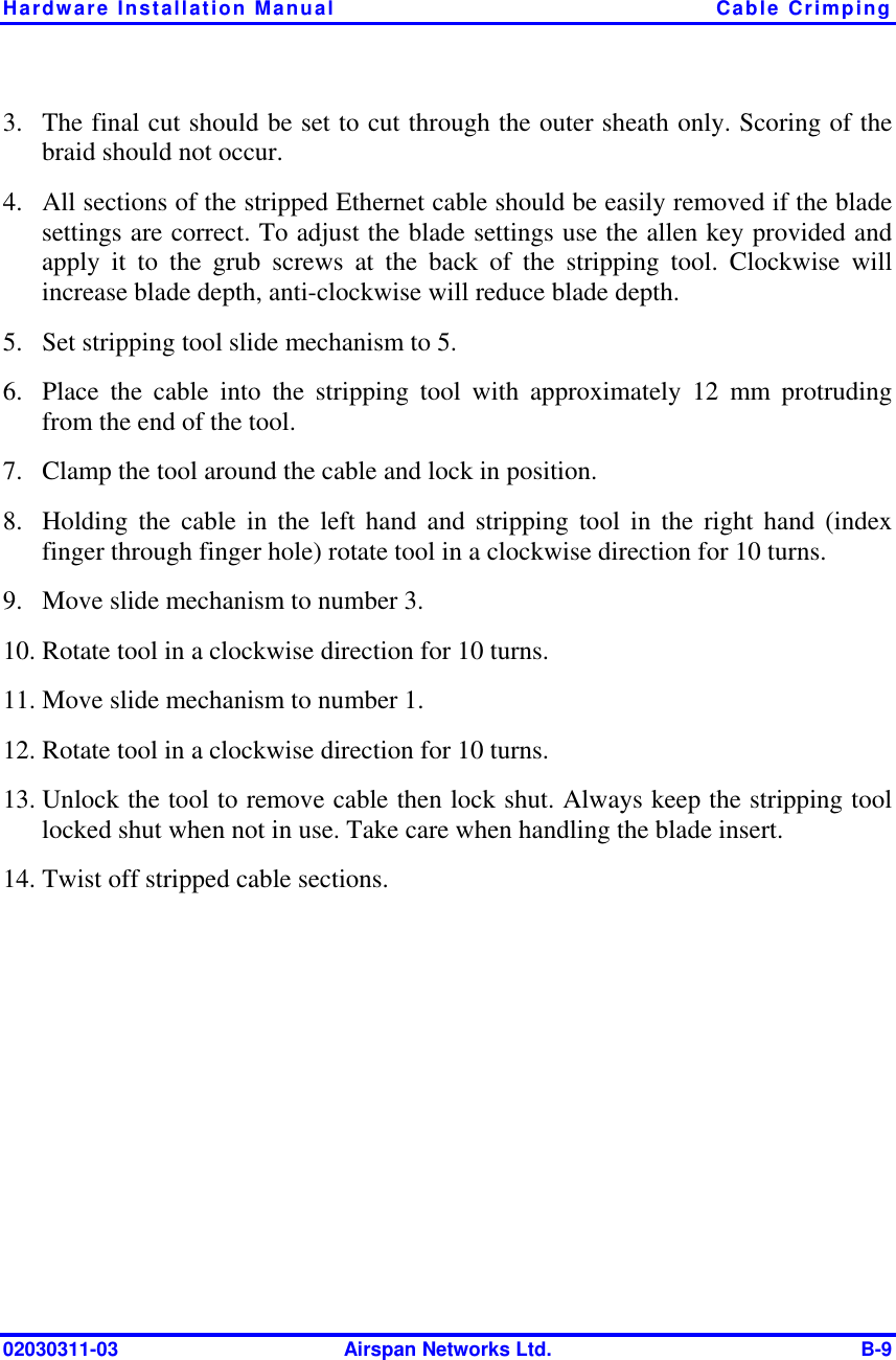
![Installing the BSR Hardware Installation Manual 4-2 Airspan Networks Ltd. 02030311-03 4.1. Overview The BSR is the center of the WipLL system. The BSR provides last-mile wireless connectivity by connecting the customer’s backhaul network to the subscriber’s wireless unit (Subscriber Premises Radio [SPR]). In addition, the BSR is responsible for synchronizing the WipLL network (i.e., synchronizing SPRs/IDRs). For base stations consisting of only a single BSR, the BSR is typically powered and connected to the customer’s backhaul by the WipLL Subscriber Data Adapter (SDA). For base stations consisting of multiple BSRs, the BSRs are powered and connected to the customer’s backhaul by the WipLL Base Station Distribution Unit (BSDU). The BSR is available in two models: BSR with an internal antenna providing 60° sector coverage; and a BSR with an N-type port for connection to an optional third-party external antenna.](https://usermanual.wiki/Airspan-Networks/AIRSPAN-BSR/User-Guide-370276-Page-49.png)