Airspan Networks AIRSPAN-BSR Base Station Radio User Manual Revised
Airspan Networks Inc Base Station Radio Users Manual Revised
Users Manual Revised

Connecting the World with Wireless Access Solutions
WipLL
WipLLWipLL
WipLL
Wireless IP-Based Local Loop System
Hardware Installation Manual
For
Release 4.2A

Revision Record: WipLL Hardware Installation Manual for Release 4.0
Pub. Rev. Date Update Description
- Nov-00 First edition and printing. (Marconi)
- Mar-01 WipLL Release 1.4 (Marconi)
- Apr-01 WipLL Release 2.0 (Marconi)
- Jul-01 WipLL Release 2.2 (Marconi)
- Nov-01 WipLL Release 2.6 (Marconi)
- Jun-02 WipLL Release 3.0A (Marconi)
01 Feb-03 WipLL Release 4.0. Author: InterDoc. Updating Airspan template and content
(connector pinouts; cable crimping, and general)
02 May-03 WipLL Release 4.2F. Author: InterDoc. Adding graphics, deleting BSR with
serial port.
03 Jul-03 WipLL Release 4.2A. Author: InterDoc. Updating Chapter 1 for Transparent
Bridging; 5.8 GHz; 2.8 GHz.
Publication No. 02030311-03
Airspan Ltd.
Cambridge House
Oxford Road
Uxbridge
Middlesex
UB8 1UN
Tel: (44)-895 467100
Web site: http//www.airspan.com
Copyright by Airspan Networks LTD., 2003. All rights reserved worldwide.
The information contained in this document is proprietary and is subject to all relevant copyright, patent and other
laws protecting intellectual property, as well as any specific agreement protecting Airspan Networks LTD. rights in
the aforesaid information. Neither this document nor the information contained herein may be published,
reproduced or disclosed to third parties, in whole or in part, without the express, prior, written permission of
Airspan Networks LTD. In addition, any use of this document or the information contained herein for any purposes
other than those for which it was disclosed is strictly forbidden.
Airspan Networks LTD. reserves the right, without prior notice or liability, to make changes in equipment design or
specifications.
Information supplied by Airspan Networks LTD. is believed to be accurate and reliable. However, no responsibility
is assumed by Airspan Networks LTD. for the use thereof nor for the rights of third parties which may be effected
in any way by the use thereof.
Any representation(s) in this document concerning performance of Airspan Networks LTD. product(s) are for
informational purposes only and are not warranties of future performance, either express or implied. Airspan
Networks LTD. standard limited warranty, stated in its sales contract or order confirmation form, is the only
warranty offered by Airspan Networks LTD. in relation thereto.
This document may contain flaws, omissions or typesetting errors; no warranty is granted nor liability assumed in
relation thereto unless specifically undertaken in Airspan Networks LTD. sales contract or order confirmation.
Information contained herein is periodically updated and changes will be incorporated into subsequent editions. If
you have encountered an error, please notify Airspan Networks LTD. All specifications are subject to change
without prior notice.

Hardware Installation Manual Contents
02030311-03 Airspan Networks Ltd. i
Contents
About this Manual................................................................................................. vii
Purpose........................................................................................................ vii
Targeted Audience....................................................................................... vii
Organization of this manual.......................................................................... vii
Technical support........................................................................................ viii
1. Introduction .............................................................................................. 1-1
1.1. Main Features ..................................................................................... 1-2
1.2. Customer Benefits............................................................................... 1-3
1.3. System Architecture ............................................................................ 1-4
1.3.1. Base Station ......................................................................... 1-5
1.3.2. Subscriber Site ..................................................................... 1-8
1.3.3. Network Operations Center................................................ 1-11
1.4. Applications....................................................................................... 1-12
1.4.1. Broadband Data Access..................................................... 1-12
1.4.2. High Speed Internet Access............................................... 1-13
1.4.3. Voice over IP ...................................................................... 1-14
1.4.4. Repeater Solution............................................................... 1-15
2. Safety Guidelines ..................................................................................... 2-1
2.1. General Safety Guidelines .................................................................. 2-2
2.2. Electrical Safety Guidelines................................................................. 2-2
2.2.1. Handling Electrostatic Devices............................................. 2-3
2.2.2. Grounding............................................................................. 2-4
2.3. Lightening Protection........................................................................... 2-4

Contents Hardware Installation Manual
ii Airspan Networks Ltd. 02030311-03
2.4. Preventing Radio Interference............................................................. 2-5
2.5. Cabling ................................................................................................ 2-6
2.5.1. Cable Labeling...................................................................... 2-7
3. Unpacking and Required Tools .............................................................. 3-1
3.1. Unpacking and Verifying Contents...................................................... 3-1
3.1.1. Base Station Equipment....................................................... 3-2
3.1.2. Customer Premises Equipment............................................ 3-6
3.2. Required Tools.................................................................................. 3-11
Part I: Installing WipLL Base Station Equipment
4. Installing the BSR..................................................................................... 4-1
4.1. Overview ............................................................................................. 4-2
4.2. Physical Dimensions and Basic Design .............................................. 4-3
4.3. Cable Installation Guidelines............................................................... 4-4
4.4. Connecting the BSR for Serial Configuration...................................... 4-6
4.5. Connecting BSR to the Backhaul Network........................................ 4-10
4.5.1. Through the SDA................................................................ 4-10
4.5.2. Through the BSDU ............................................................. 4-14
4.6. Conecting a Third-Party External Antenna (Optional)....................... 4-18
4.7. Connecting the BSR to Power........................................................... 4-19
4.8. Mounting the BSR ............................................................................. 4-20
4.8.1. Minimum Distance Between BSRs..................................... 4-20
4.8.2. Wall Mounting..................................................................... 4-21
4.8.3. Pole Mounting..................................................................... 4-24

Hardware Installation Manual Contents
02030311-03 Airspan Networks Ltd. iii
5. Installing the BSDU.................................................................................. 5-1
5.1. BSDU Characteristics.......................................................................... 5-2
5.2. Mounting the BSDU in the Cabinet ..................................................... 5-2
5.3. Cabling the BSDU ............................................................................... 5-4
5.3.1. Connecting BSRs to the BSDU ............................................ 5-6
5.3.2. Connecting the GPS antenna............................................... 5-7
5.3.3. Connecting to 100Base-T Networks..................................... 5-8
5.3.4. Daisy-Chaining BSDUs ........................................................ 5-8
5.3.5. Connecting Sync IN/OUT ports .......................................... 5-10
5.3.6. Connecting the Power Management port........................... 5-12
5.3.7. Connecting Cables for BSDU Serial Management............. 5-15
5.3.8. Connecting Cables for BSDU Network IP Management .... 5-17
5.4. Connecting Power............................................................................. 5-21
5.4.1. Grounding (Earthing) the BSDU......................................... 5-21
5.4.2. Connecting to the Power Supply (BSPS) ........................... 5-23
5.5. LED Indicators................................................................................... 5-25
5.5.1. BSR’s LEDs........................................................................ 5-25
5.5.2. 100Base-T LEDs ................................................................ 5-26
5.5.3. Status LEDs........................................................................ 5-27
6. Installing the GPS..................................................................................... 6-1
6.1. Mounting the GPS............................................................................... 6-2
6.2. Connecting the GPS to the BSDU....................................................... 6-3
7. Installing the BSPS .................................................................................. 7-1
7.1. General Site Requirements................................................................. 7-2
7.2. BSPS Components ............................................................................. 7-4
7.2.1. Installing BSPS Batteries...................................................... 7-8
7.3. Installation Summary of the BSPS .................................................... 7-11
7.3.1. Connecting Power to BSDUs ............................................. 7-13
7.3.2. Installing the Rectifier ......................................................... 7-16

Contents Hardware Installation Manual
iv Airspan Networks Ltd. 02030311-03
7.3.3. Calibrating the Rectifier ...................................................... 7-16
7.3.4. Operating the System Controller ........................................ 7-19
7.4. Connecting the BSPS Management Cables ..................................... 7-21
7.4.1. BSPS Troubleshooting ....................................................... 7-22
7.5. BSPS Cabinet Cabling ...................................................................... 7-23
7.5.1. BSPS Cabinet Grounding................................................... 7-25
7.5.2. BSPS Equipment Supplementary Grounding..................... 7-25
7.5.3. BSPS Cabinet Power Requirements .................................. 7-26
Part II: Installing WipLL Customer Premises Equipment
8. Installing the SPR..................................................................................... 8-1
8.1. Overview ............................................................................................. 8-1
8.2. Physical Dimensions and Basic Design .............................................. 8-5
8.3. Cable Guidelines................................................................................. 8-6
8.4. Mounting the SPR ............................................................................... 8-8
8.4.1. Minimum Distance between SPRs ....................................... 8-8
8.4.2. Wall-Mounting....................................................................... 8-9
8.4.3. Pole-Mounting .................................................................... 8-12
8.5. Connecting an External Third-Party Antenna (Optional)................... 8-15
8.6. Connecting to a PC for Initial Serial Configuration............................ 8-16
8.7. Connecting to the SDA...................................................................... 8-20
8.8. Connecting Power............................................................................. 8-24
9. Installing the SDA..................................................................................... 9-1
9.1. Overview ............................................................................................. 9-2
9.2. Physical Dimensions and Basic Design .............................................. 9-4
9.3. Mounting the SDA ............................................................................... 9-6
9.3.1. Desktop-Mounting ................................................................ 9-6
9.3.2. Wall-Mounting....................................................................... 9-7
9.4. Connecting to the SPR........................................................................ 9-8

Hardware Installation Manual Contents
02030311-03 Airspan Networks Ltd. v
9.5. Connecting to the Subscriber’s Ethernet Network............................... 9-8
9.5.1. Connecting to PCs.............................................................. 9-11
9.5.2. Connecting to a Hub........................................................... 9-13
9.5.3. Connecting to a VoIP Network ........................................... 9-16
9.6. Connecting AC Power....................................................................... 9-18
9.7. LED Display....................................................................................... 9-22
9.7.1. SDA-4H .............................................................................. 9-22
9.7.2. SDA-4S Models.................................................................. 9-24
10. Installing and Configuring the IDR ....................................................... 10-1
10.1. Mounting the IDR ............................................................................ 10-3
10.1.1. Desk Mounting.................................................................. 10-3
10.1.2. Wall and Pole Mounting.................................................... 10-6
10.1.3. Connecting a Third-Party External Antenna................... 10-11
10.1.4. Connecting to an Ethernet Network................................ 10-11
10.2. Positioning IDR for Optimum RF Reception.................................. 10-12
10.3. Connecting Power Supply............................................................. 10-14
10.3.1. Power LEDs.................................................................... 10-16
10.4. Configuring the IDR....................................................................... 10-16
10.4.1. Connecting to a PC ........................................................ 10-16
10.4.2. Configuring the SPR using WipConfig............................ 10-19

Contents Hardware Installation Manual
vi Airspan Networks Ltd. 02030311-03
A. Glossary....................................................................................................A-1
B. Cable Crimping.........................................................................................B-1
B.1. Crimping CAT-5e/15-Pin D-Type Cable Connectors ..........................B-1
B.1.1. Stripping the Cable...............................................................B-3
B.1.2. Crimping the Cable ..............................................................B-4
B.1.3. Inspecting the Crimped Connector.......................................B-5
B.1.4. Housing the Connector ........................................................B-7
B.2. Crimping N-type Connectors...............................................................B-8
B.2.1. Stripping the Cable...............................................................B-8
B.2.2. Assembling the Connector.................................................B-10
B.2.3. Crimping.............................................................................B-11
B.3. Crimping GPS Cable Connectors .....................................................B-12
C. Technical Specifications .........................................................................C-1
C.1. Base Station WipLL Equipment..........................................................C-2
C.1.1. Base Station Radio (BSR) ...................................................C-2
C.1.2. Point-to-Point Radio (PPR)..................................................C-5
C.1.3. Base Station Distribution Unit (BSDU).................................C-6
C.1.4. Base Station Power Supply (BSPS) ....................................C-8
C.1.5. GPS antenna .....................................................................C-10
C.2. Customer Premises WipLL Equipment.............................................C-12
C.2.1. Subscriber Premises Radio (SPR).....................................C-12
C.2.2. Subscriber Data Adapter (SDA).........................................C-15
C.2.3. Indoor Data Radio (IDR) ....................................................C-18

02030311-03 Airspan Networks Ltd. vii
About this Manual
About this ManualAbout this Manual
About this Manual
This section discusses the purpose, targeted audience, references, organization, and
technical support of the WipLL Hardware Installation manual.
Purpose
This manual describes the installation procedures of Airspan’s WipLL system,
release 4.0. This installation includes WipLL equipment at the base station and at the
subscriber’s premises (i.e., CPE equipment).
Although this manual provides minimum software configuration information for
certain WipLL units, it is not comprehensive. For detailed software configuration
information, see the WipLL Commissioning Manual.
Targeted Audience
This manual is intended for the person who is responsible for installing the WipLL
system, and who should be familiar with electronic circuitary and wiring.
Organization of this manual
This manual is organized into the following chapters and parts:
! Chapter 1, “WipLL System Overview”—provides a brief overview of the
WipLL system.
! Chapter 2, “Safety Guidelines”—lists the safety guidelines for handling cables
and electricity during the installation.

About this Manual Hardware Installation Manual
viii Airspan Networks Ltd. 02030311-03
! Chapter 3, “Unpacking and Required Tools”—lists the equipment provided by
Airspan, as well as the tools needed for installation.
! Part 1, “Installing WipLL Base Station Equipment”—includes the following
chapters concerned with installing WipLL equipment at the base station:
! Chapter 4, “Installing the Base Station Radio”
! Chapter 5, “Installing the Base Station Distribution Unit”
! Chapter 6, “Installing the GPS”
! Chapter 7, “Installing the Base Station Power Supply”
! Part 2, “Installing WipLL Customer Premises Equipment”—includes the
following chapters concerned with installing WipLL equipment at the
subscriber’s premises:
! Chapter 8, “Installing the Subscribers Premises Radio”
! Chapter 8, “Installing the Subscriber Data Adapter”
! Chapter 9, “Installing the Indoor Data Radio”
! Appendix A, “Glossary”—glossary of terms used in this manual
! Appendix B, “Cable Crimping”—describes the crimping procedure for 15-Pin
D-type, N-type, and GPS connectors.
! Appendix C, “Technical Specifications”—lists the technical specifications of
the WipLL units.
Technical support
For service and support for your WipLL system, contact your regional Airspan
representative, or Airspan’s Technical Assistance Center (TAC) at:
! Telephone hotline: (+972)-8-929 2266
! E-mail: Wipll.tech_support@Airspan.com

02030311-03 Airspan Networks Ltd. 1-1
Introduction
IntroductionIntroduction
Introduction
Airspan’s AS WipLL system (hereafter referred to as WipLL) is a low-cost, high-
performance point-to-multipoint IP-based Broadband Fixed Wireless (BFW) Access
solution. WipLL provides wireless local-loop (last-mile) connectivity designed to
deliver high-speed data, Voice over IP (VoIP), and multimedia services to
residential, SOHO (small office/home office), and SME (small medium enterprise).
WipLL offers service providers an integrated access solution, providing quick-to-
market deployment and low-market entry cost for broadband services.
WipLL provides connectivity speeds of up to 4 Mbps in the licensed 2.8 GHz, 3.x
GHz, and Multichannel Multipoint Distribution Services (MMDS), and unlicensed
2.4 GHz (ISM) and 5.8 GHz radio frequency bands. In the 5.8 GHz band, the
WipLL system supports 3 Mbps and 4 Mbps transmission speeds. For 1, 2, and 3
Mbps, WipLL implements the Frequency Hopping spread spectrum mode; for 4
Mbps, WipLL implements the Hybrid spread spectrum mode. Each WipLL base
station, at maximum configuration, supports up to 3,024 subscribers.
WipLL enables interconnection with the Public Switched Telephone Network
(PSTN) by the use of an IP-to-PSTN gateway. WipLL provides VoIP by its
interoperability with a wide range of third-party products such as residential
gateways (RGW), access gateways, gatekeepers, and softswitches.
WipLL utilizes air protocol technology for wireless packet switching using
Frequency Hopping technology. In addition, WipLL's in-house Preemptive Polling
Multiple Access (PPMA) air MAC protocol technology, which recognizes
transmission type and assigns bandwidth, is highly efficient—80% throughput (e.g.,
80% of 4 Mbps = 3.2 Mbps net capacity)—allowing multiple concurrent subscribers
to utilize bandwidth.
1

Introduction Hardware Installation Manual
1-2 Airspan Networks Ltd. 02030311-03
WipLL provides bandwidth management by supporting Committed Information
Rate (CIR) and Maximum Information Rate (MIR), guaranteeing bandwidth levels
to subscribers. In addition, WipLL supports VLANs/VPNs based on IEEE
802.1Q/p. WipLL supports IP routing and PPPoE bridging, as well as transparent
bridging, allowing easy IP addressing schemes.
WipLL provides embedded security features such as IP (packet) filters based on
addresses, protocols, and applications.
The WipLL system provides SNMP-based management, allowing remote and local
management, configuration, and monitoring of WipLL equipment.
1.1. Main Features
The WipLL system includes the following main features:
! Low initial investment, maximum return on investment (ROI)
! IP-based air interface supporting high speed data, VoIP, and multimedia services
! Modular architecture with flexible deployment architectures
! 4 Mbps (3.2 Mbps net) per sector—up to 24 sectors per base station
! Compact, integrated design allowing easy and quick deployment
! Advanced Quality of Service (QoS)
! Simultaneous support of IP routing and PPPoE bridging
! Supports Transparent bridging
! Bandwidth management: CIR and MIR
! Supports 802.1Q/p for VLANs/VPNs and end-to-end QoS
! Supports local and remote SNMP-based management, providing an intuitive
GUI for easy management

Hardware Installation Manual Introduction
02030311-03 Airspan Networks Ltd. 1-3
1.2. Customer Benefits
The WipLL system provides the following customer benefits and advantages over
competitors:
! No IF or RF cables required for indoor unit-to-outdoor unit (IDU-to-ODU)
connectivity, providing a more cost-effective and easier installation. Instead of
IF/RF cables, WipLL implements standard CAT-5 Ethernet cables.
! Scalability and modular architecture allows customers to add equipment when
needed, thereby allowing low initial cost entry and pay-as-you-grow strategy.
Unlike competitors, WipLL is not a chassis-based design, providing flexibility
and saving space at the base station.
! WipLL's open architecture allows interoperability with multi-vendor products
such as residential gateways (RGW), access gateways, gatekeepers, and
softswitches, thereby, operating seamlessly in multi-vendor environments.
! WipLL’s proprietary PPMA air MAC protocol is highly efficient—80%
throughput—allowing multiple concurrent subscribers to utilize bandwidth
without network degradation (from collisions and high BER).
! WipLL is both an IP router and a PPPoE bridge.
! Supports Transparent bridging for easy implementation of IP addressing
schemes
! WipLL’s IP routing provides efficiency and eliminates the need for additional
hardware.
! Enhanced QoS—based on IP addresses, protocols, and applications.
! End-to-end QoS—based on DiffServ/TOS or 802.1p.
! Embedded security features such as IP (packet) filters based on addresses,
protocols, and applications.
! Rich networking packages such as 802.1Q/p VLANs/VPNs.
! Long distance radio coverage.
Introduction Hardware Installation Manual
1-4 Airspan Networks Ltd. 02030311-03
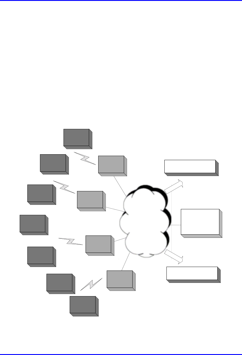
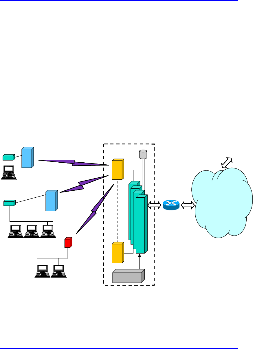
1.3. System Architecture
The WipLL system architecture is composed of the following three basic areas (see
Figure 1-1):
! Base station site: consists of WipLL access units that interface between the
provider’s backbone and the WipLL system.
! Subscriber site: consists of WipLL customer premises equipment (CPE) that
interfaces between the base station and the subscriber’s network.
! Network operations center (NOC): consists of the WipLL SNMP-based
management system that manages the entire WipLL system.
Subscriber
Site
Subscriber
Site
Subscriber
Site
Subscriber
Site
Subscriber
Site
Subscriber
Site
Subscriber
Site
Base Station
Site
Base Station
Site
Base Station
Site
Base Station
Site
Network
Non IP Systems
Network
Operating
Centre
Non WiPLL
Users
Figure 1-1: WipLL System Architecture
Hardware Installation Manual Introduction
02030311-03 Airspan Networks Ltd. 1-5
1.3.1. Base Station
The WipLL base station provides a radio link between the subscriber and the service
provider's backbone to provide high-speed data access, Internet access, and VoIP.
The WipLL base station equipment consists of a radio transceiver that transmits and
receives signals to and from the subscriber, and of various optional Ethernet hubs
that connect the WipLL transceiver to the service provider’s backbone, through a
100BaseT Ethernet connection.
The WipLL base station is comprised of the following units (see Figure 1-3):
! Base Station Radio (BSR):
The BSR is a radio transceiver that provides the wireless link between the
subscriber and the provider's backbone. Each BSR has 60-degree radio coverage,
serving up to 126 subscribers in that sector.
The BSR is installed outside the base station site, typically mounted on a pole.
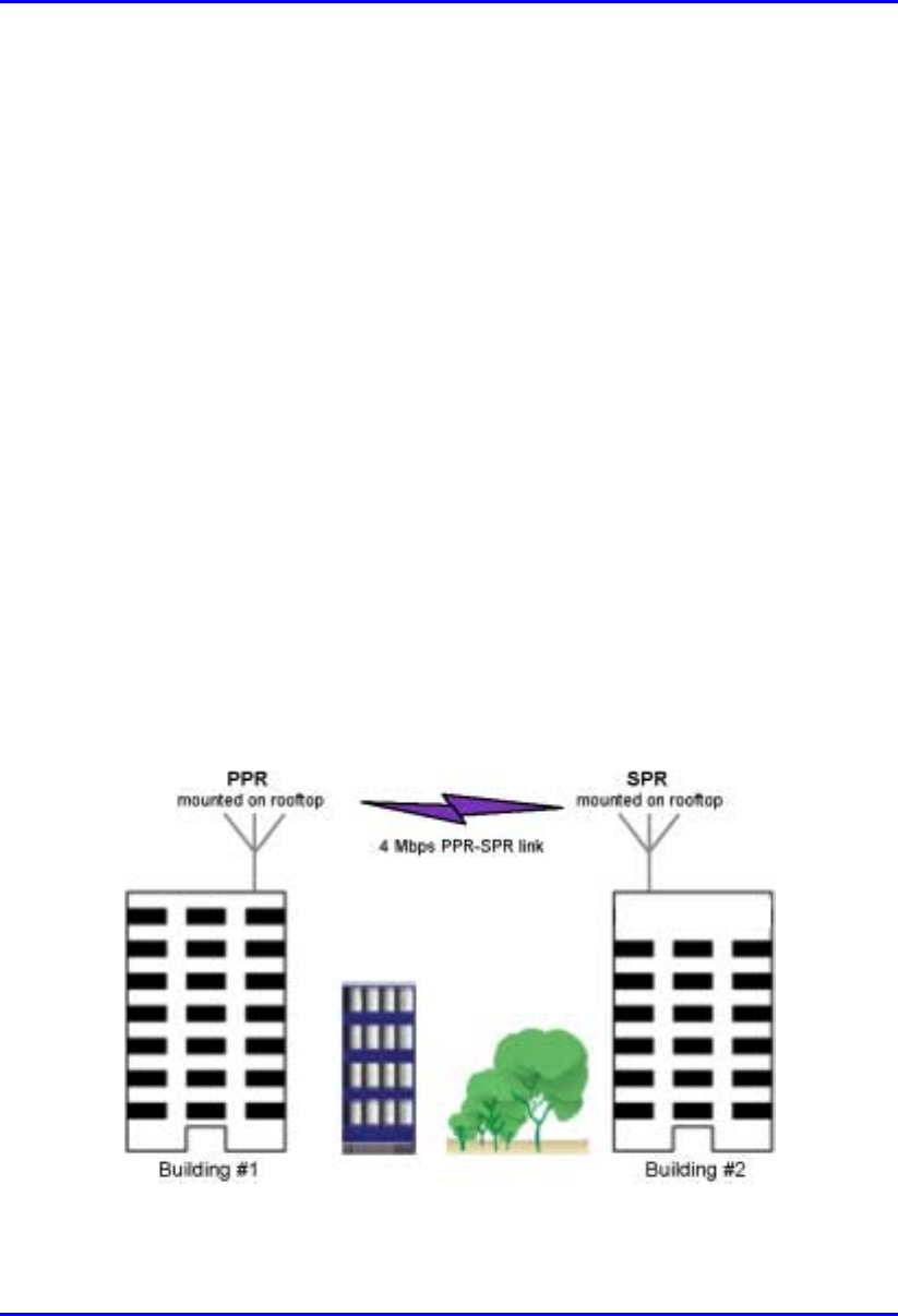
! Point-to-Point Radio (PPR):
The PPR device is similar to the BSR, but implemented in a point-to-point radio
configuration providing wireless communication with a single remote WipLL
radio unit (i.e., Subscriber Premises Radio).
Figure 1-2: PPR in a building-to-building application

Introduction Hardware Installation Manual
1-6 Airspan Networks Ltd. 02030311-03
! Subscriber Data Adapter (SDA):
The SDA is implemented at base stations comprised of a single BSR. The SDA
provides the BSR with -48 VDC power supply and Ethernet connectivity to the
provider's backbone. The SDA is installed inside, connected to the BSR with a
CAT-5 cable.
! Base Station Distribution Unit (BSDU):
The BSDU is implemented at base stations comprising multiple BSRs. The
BSDU provides BSRs with –48 VDC power supply, connectivity to the
provider's backbone, and frequency hop synchronization. The BSDU is installed
inside, connected to BSRs with CAT-5 cables.
Each BSDU can support up to six BSRs, and up to four BSDUs can be daisy-
chained to support a maximum of 24 BSRs. Therefore, a base station at
maximum configuration can serve up to 3,024 subscribers.
! Base Station Power Supply (BSPS):
The BSPS is an optional WipLL unit that provides AC-to-DC power conversion
and power redundancy to BSDUs.
! Global Positioning System (GPS) antenna:
The GPS antenna is a rugged, self-contained GPS receiver and antenna that
receives a universal GPS satellite clock signal. The GPS connects to the BSDU
and synchronizes multiple base stations to allow the WipLL network to operate
with the same clock, and eliminating radio frequency ghosting effects.
Hardware Installation Manual Introduction
02030311-03 Airspan Networks Ltd. 1-7
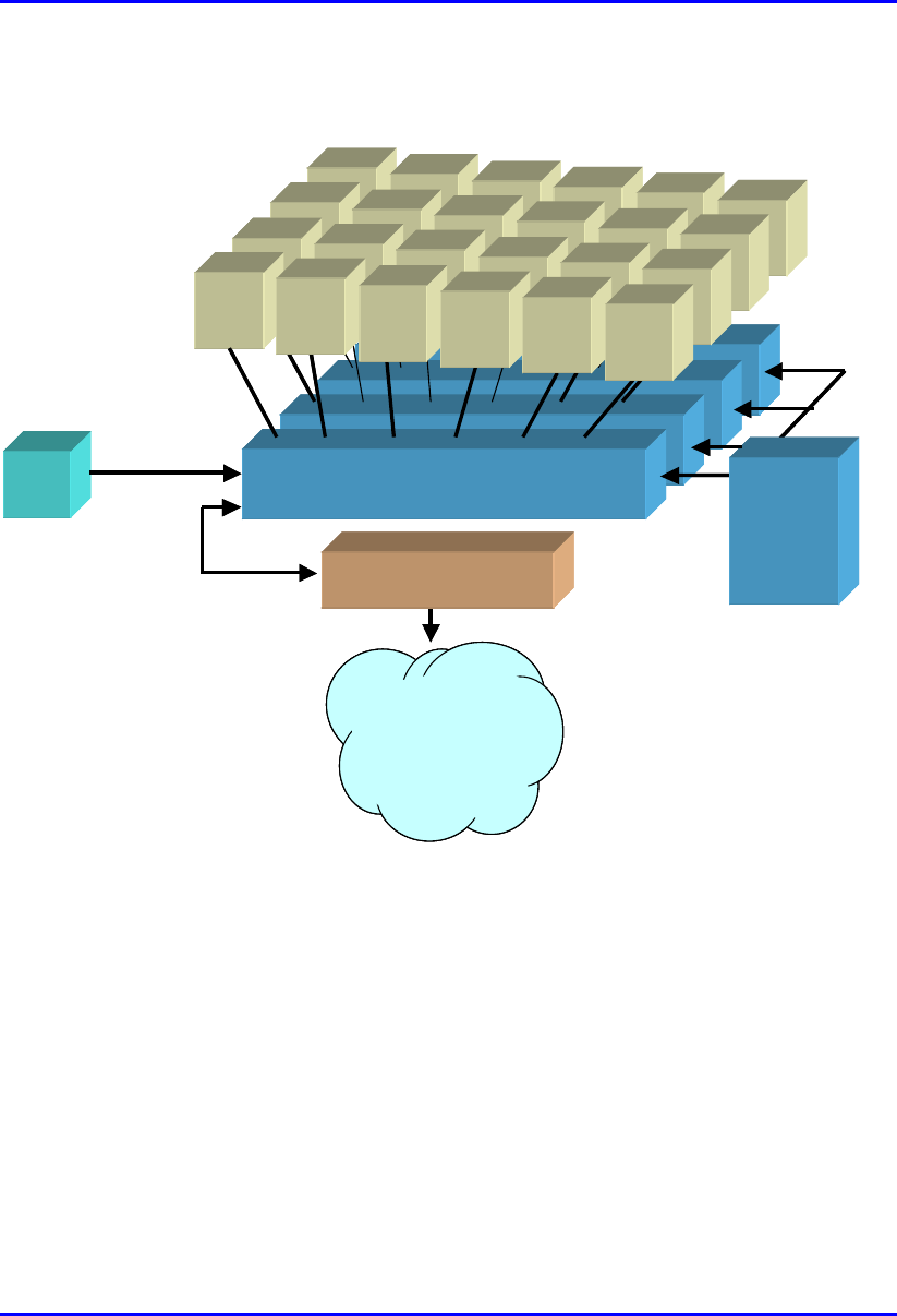
Figure 1-3 shows the WipLL base station devices and their interconnections.
BSR
BSDU
BSR BSR BSR BSR BSR
BSR
BSDU
BSR BSR BSR BSR BSR
BSR
BSDU
BSR BSR BSR BSR BSR
BSR
BSRBSR
BSR
BSDU
BSDUBSDU
BSDU
-
--
-48
4848
48 VDC
VDCVDC
VDC
100
100100
100B
BB
BaseT
aseTaseT
aseT BSPS
BSPSBSPS
BSPS
BSR
BSRBSR
BSR BSR
BSRBSR
BSR BSR
BSRBSR
BSR BS
SS
SRBSR
BSRBSR
BSR
GPS
GPSGPS
GPS
Backbone
BackboneBackbone
Backbone
(
((
(IP, ATM,FR, MPLS
IP, ATM,FR, MPLSIP, ATM,FR, MPLS
IP, ATM,FR, MPLS)
))
)
Interface unit
Interface unit Interface unit
Interface unit
(
((
(e
ee
e.
..
.g
gg
g.
. .
. router, switch
router, switchrouter, switch
router, switch)
))
)
BSR
BSDU
BSR BSR BSR BSR BSR
BSR
BSDU
BSR BSR BSR BSR BSR
BSR
BSDU
BSR BSR BSR BSR BSR
BSR
BSRBSR
BSR
BSDU
BSDUBSDU
BSDU
-
--
-48
4848
48 VDC
VDCVDC
VDC
100
100100
100B
BB
BaseT
aseTaseT
aseT BSPS
BSPSBSPS
BSPS
BSR
BSRBSR
BSR BSR
BSRBSR
BSR BSR
BSRBSR
BSR BS
SS
SRBSR
BSRBSR
BSR
GPS
GPSGPS
GPS
Backbone
BackboneBackbone
Backbone
(
((
(IP, ATM,FR, MPLS
IP, ATM,FR, MPLSIP, ATM,FR, MPLS
IP, ATM,FR, MPLS)
))
)
Interface unit
Interface unit Interface unit
Interface unit
(
((
(e
ee
e.
..
.g
gg
g.
. .
. router, switch
router, switchrouter, switch
router, switch)
))
)
Figure 1-3: WipLL base station units (maximum configuration)

Introduction Hardware Installation Manual
1-8 Airspan Networks Ltd. 02030311-03
1.3.2. Subscriber Site
The WipLL subscriber site is located at the service provider's subscribers’ premises.
The WipLL subscriber site equipment consists of a radio transceiver that receives
and transmits signals from and to the base station. The WipLL radio transceiver
provides the subscriber with high-speed data access, Internet access, and VoIP at up
to 3.2 Mbps. The WipLL transceiver connects to the subscriber’s network or PC via
WipLL’s Ethernet hub (i.e., Subscriber Data Adapter).
The WipLL system can group subscribers into VLANs, as well as assign MIR and
CIR levels to each subscriber, guaranteeing bandwidth to subscribers.
The WipLL subscriber site is comprised of the following units:
! Subscriber Premises Radio (SPR):
The SPR is a radio transceiver that provides a wireless link between the base
station and the subscriber’s network. The SPR is installed outside the
subscriber's premises, typically on a roof.
! Subscriber Data Adapter (SDA):
The SDA is a hub/switch that provides the SPR with -48 VDC power supply and
Ethernet connectivity to the subscriber’s network/PC. The SDA is installed
inside the subscriber's premises and is connected to the SPR by a CAT-5 cable.
The SDA models include the following:
! SDA-1: provides one 10BaseT connection to the subscriber’s computer
and/or network.
! SDA-4H: provides a hub and four 10BaseT interfaces to the subscriber’s
computers and/or networks. The hub interface is a crossed Ethernet cable that
can connect to another hub or LAN switch. Alternatively, it may be
connected to another PC via a crossed Ethernet cable.

Hardware Installation Manual Introduction
02030311-03 Airspan Networks Ltd. 1-9
! SDA-4S models: integrated LAN switches, providing four 10/100BaseT
ports for interfacing with the subscriber’s PCs/network) These models
include the following:
− SDA-4S (standard): Standard integrated LAN switch, providing four
10/100BaseT interfaces to the subscriber’s computers.
− SDA-4S/VL: Provides VLANs between its ports and the SPR, ensuring
privacy between users of different ports (i.e., multi-tenant VLAN
security). For example, all users connected to Port 1 do not “see” users
connected to Port 2.
− SDA-4S/1H3L: Provides a high priority port (left-most port) for VoIP
traffic.
− SDA-4S/VL/1H3L: Combines the functionality of the SDA-4S/VL and
SDA-4S/1H3L models (VLAN for each port and a high priority port for
VoIP).
! Indoor Radio Adapter (IDR)—optional unit:
The IDR functions as a transceiver and a hub, eliminating the need for an SPR
and SDA. The IDR is installed inside the subscriber's premises, typically
mounted on a wall, desktop, or pole. The IDR is connected to a third-party
antenna, which is typically mounted outside to provide line-of-site with the base
station.
! Residential Gateway (RGW)—optional unit:
The RGW is a third-party unit that provides gateway support for VoIP. The
RGW is typically connected to the SDA through a 10BaseT port.
Introduction Hardware Installation Manual
1-10 Airspan Networks Ltd. 02030311-03
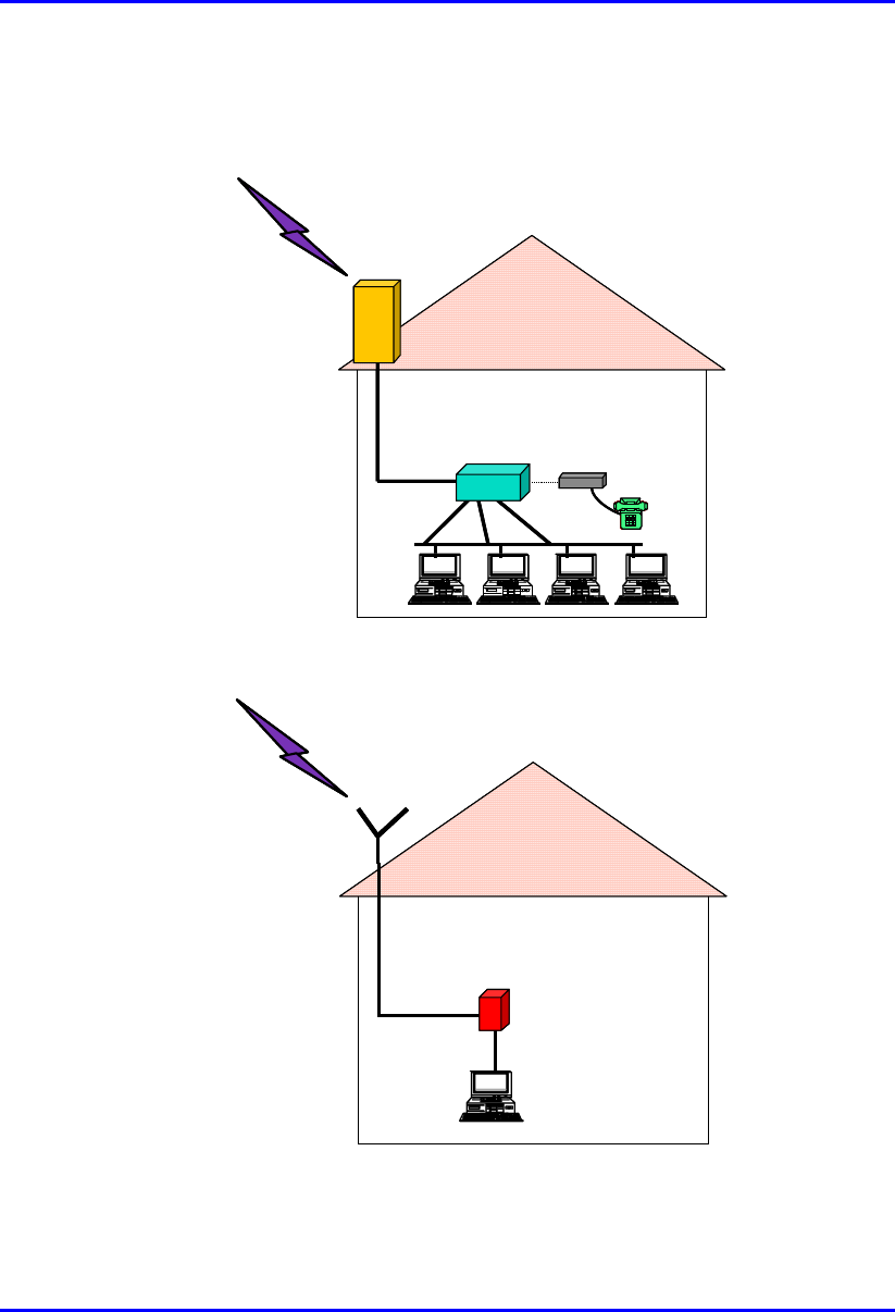
Figure 1-4 and Figure 1-5 display the WipLL customer premises equipment and
their interconnections.
To BSR
To BSRTo BSR
To BSR
RGW
RGWRGW
RGW
SDA
SPR
To BSR
To BSRTo BSR
To BSR
RGW
RGWRGW
RGW
SDA
SPR
Figure 1-4: Subscriber site with SPR and SDA units (optional RGW unit)
To BSR External
ExternalExternal
External
antenna
antennaantenna
antenna
RF cable
IDR
To BSR External
ExternalExternal
External
antenna
antennaantenna
antenna
RF cable
IDR
Figure 1-5: Subscriber site with IDR and third-party external antenna

Hardware Installation Manual Introduction
02030311-03 Airspan Networks Ltd. 1-11
1.3.3. Network Operations Center
Airspan’s WipLL system provides state-of-the-art, use-friendly management tools
for managing the WipLL system. These management tools provide fault,
configuration, performance, and security management of the WipLL system.
The WipLL system provides two management tools:
! WipManage™--WipLL network (and element) management system tool.
WipManage is a Windows-based, stand-alone WipLL application that provides a
user-friendly Graphic User Interface (GUI) for managing the WipLL system.
WipManage provides local and remote network management that is based on
Simple Network Management Protocol (SNMP). WipManage provides
configuration, fault and alarms, security, and bandwidth management to all the
WipLL units—WipLL base station equipment and WipLL CPE.
! WipConfig™--WipLL initial configuration tool.
WipConfig is an easy-to-use, Windows-based application that provides local
initial configuration to WipLL hardware. This initial configuration includes, for
example, assigning the units IP addresses and positioning the antenna (or
transceiver) for optimal reception.

Introduction Hardware Installation Manual
1-12 Airspan Networks Ltd. 02030311-03
1.4. Applications
The following subsections provide examples of typical WipLL applications.
1.4.1. Broadband Data Access
Using a standard PSTN modem in circuit-switched networks, subscribers are limited
to 56 Kbps of throughput, and in most cases, to 28.8 Kbps. From the operator's
perspective, once a subscriber has dialed up with a PSTN modem, a full 128 Kbps
channel is occupied for as long as the session lasts.
WipLL subscribers are limited only by their own configuration, with a maximum of
4 Mbps—50 times faster than the fastest PSTN modem. However, subscribers do
not necessarily consume more bandwidth from the operator, since bandwidth is used
only when a data packet is transmitted.
These characteristics of WipLL make it suitable for providing data access to
subscribers while maintaining best usage of bandwidth and capacity.
Hardware Installation Manual Introduction
02030311-03 Airspan Networks Ltd. 1-13
1.4.2. High Speed Internet Access
One of the advantages of WipLL is the fact that subscribers are "always on" Internet.
This means that there is no dialing process and no need for the hassle involved with
dialup access. Subscribers need only to open their Web browser or e-mail to be
instantly connected.
WipLL can also distinguish between applications and subscribers, thus, enabling the
operator to provide different class of service to subscribers. For example, it can
provide different services to Web browsing and e-mail by prioritizing Web browsing
for ensuring best "Internet experience".
Figure 1-6 shows a typical WipLL application for high-speed Internet access.
Base Station Site
SPR
SDA
Ethernet LAN
IDR
IP Network
SDA
SPR
Router
n
BSR
B
S
D
U
10BaseT
B
S
D
U
B
S
D
U
B
S
D
U
GPS
1
To ISPs
Ethernet LAN
BSPS
Base Station Site
SPR
SDA
Ethernet LAN
IDR
IP Network
SDA
SPR
Router
n
BSR
B
S
D
U
10BaseT
B
S
D
U
B
S
D
U
B
S
D
U
GPS
1
To ISPs
Ethernet LAN
BSPS
Figure 1-6: Typical WipLL Application for High-Speed Internet Access
Introduction Hardware Installation Manual
1-14 Airspan Networks Ltd. 02030311-03
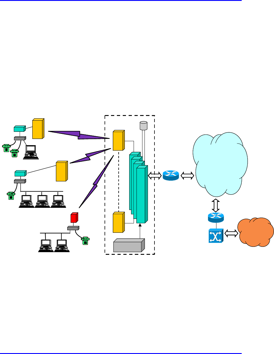
1.4.3. Voice over IP
The WipLL system enables customers the flexibility of migration from a data-only
network to an integrated Voice-over-IP and data network. The WipLL voice solution
provides interoperability with any IP-to-PSTN network gateway. The use of the IP-
to-PSTN gateway allows operators seamless PSTN connectivity such as SS7
(signaling network), G3-303, and V5.2 over E1, allowing deployment in multi-
national markets.
Figure 1-7 shows a typical WipLL application for VoIP.
Base Station Site
SPR
SDA
IDR
IP Network
SDA
SPR
n
BSR
B
S
D
U
10BaseT
B
S
D
U
B
S
D
U
B
S
D
U
GPS
1
BSPS
RGW
RGW
RGW
PSTN
HEG+ Gatekeeper
Router / switch
Router / switch
Base Station Site
SPR
SDA
IDR
IP Network
SDA
SPR
n
BSR
B
S
D
U
10BaseT
B
S
D
U
B
S
D
U
B
S
D
U
GPS
1
BSPS
RGW
RGW
RGW
PSTN
HEG+ Gatekeeper
Router / switch
Router / switch
Figure 1-7: Typical WipLL Application for VoIP
Hardware Installation Manual Introduction
02030311-03 Airspan Networks Ltd. 1-15
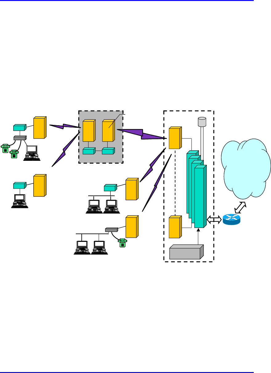
1.4.4. Repeater Solution
WipLL units can be used to provide repeater functionality. This is implemented in
where the BSR needs to be “extended” to remote subscriber sites that are blocked by
obstacles (such as trees, hills, and other typical line-of-sight obstructions) or that the
BSR-SPR (or BSR-IDR) transmission is out-of-range. Back-to-back Ethernet
connectivity of a BSR with an SPR/IDR provides the repeater capability, as
demonstrated in Figure 1-8.
Base Station Site
SPR B1
Backbone
SPR A1
SPR Ai
n
BSR
A
B
S
D
U
B
S
D
U
B
S
D
U
B
S
D
U
GPS
BSPS
SDA
Router / switch
SPR
BSR
B
SDA SDA
SPR B2
SDA SDA
Ethernet
SPR used as
a Repeater
Base Station Site
SPR B1
Backbone
SPR A1
SPR Ai
n
BSR
A
B
S
D
U
B
S
D
U
B
S
D
U
B
S
D
U
GPS
BSPS
SDA
Router / switch
SPR
BSR
B
SDA SDA
SPR B2
SDASDA SDASDA
Ethernet
SPR used as
a Repeater
Figure 1-8: WipLL Repeater Solution
In Figure 1-8, BSR A is part of a WipLL base station that is connected to the service
provider’s backbone. BSR A serves multiple SPRs, marked as SPR Ai. Two SPRs—
SPR B1 and SPR B2—cannot communicate directly with the base station.
Therefore, an SPR acts as a repeater by connecting back-to-back with BSR B (SPR
B1 and B2 are served by BSR B).

Introduction Hardware Installation Manual
1-16 Airspan Networks Ltd. 02030311-03
Notes:
- Careful planning is required to cope with issues such as interferences and
delay that are introduced by the repeater solution. For example, if the system is
used as a frequency hopping system, GPS may be required at each base
station.
- Space and frequency isolation between the “repeater SPR” and BSR B is
required.
- Bandwidth management should be calculated to support the “repeater
bandwidth”.
- IP addressing and routing tables should be configured to support the
repeater solution.

02030311-03 Airspan Networks Ltd. 2-1
Safety Guidelines
Safety GuidelinesSafety Guidelines
Safety Guidelines
This chapter outlines general safety guidelines for electricity handling, preventing
radio interference, and cable labeling when installing the WipLL system.
This chapter includes the following sections:
! General Safety Guidelines
! Electrical Safety Guidelines
! Handling Electrostatic Devices
! Grounding
! Lightening Protection
! Preventing Radio Interference
! Cabling
! Cable Labeling
− Voltage Warning Labels
− High Earth Leakage Current
− Signal Cable Designation Label
2

Safety Guidelines Hardware Installation Manual
2-2 Airspan Networks Ltd. 02030311-03
2.1. General Safety Guidelines
The following lists general safety guidelines when working with the WipLL
equipment:
! The user and the installer should be aware that changes and modifications not
expressly approved by Airspan Networks could void the user’s authority to
operate the equipment
! Never install equipment that is damaged.
! Only qualified personnel should be allowed to install, replace, and service the
WipLL equipment.
2.2. Electrical Safety Guidelines
The following lists electrical safety guidelines when working with the WipLL
equipment:
! Disconnect all power when installing
! Never install the equipment during stormy weather and lightening

Hardware Installation Manual Safety Guidelines
02030311-03 Airspan Networks Ltd. 2-3
2.2.1. Handling Electrostatic Devices
Electrostatic devices are those devices that may be damaged by the inadvertent
discharge of static electricity from a charged body. The risk of damage, due to
electrostatic discharge (ESD) to a device, may cause the device to fail suddenly, or it
may induce a partial defect within the device, which will cause subsequent
premature failure.
Static electricity can result from operators walking on floors, moving around on
chairs, from the movement of operator's clothing or even casual brushing against
racks, benches or walls.
Airspan recommends the following guidelines to be adopted to minimize the risk of
component failure due to electrostatic discharge to the device:
! WipLL devices are provided typically in see-through anti-static bags. Wherever
possible, checking and inspection of a unit should occur without removing it
from the bag.
! All operators shall wear the approved conductive overall.
! Where operators come into direct contact with any piece of electronic hardware,
operators must wear an ESD bonding wrist strap. All straps and cords should be
tested using a Wrist Strap Tester prior to use.
All operators shall wear an ESD-preventive wrist strap and cord to a suitable
non-mains earth (ESD stud) on the rack. The wrist strap cords shall have a 2
Meg Ohm resistor fitted at either end. Wrist straps should be worn in direct
contact with bare skin and not over clothing.
Warning: Under no circumstances is it permissible for units to be handled by
unprotected operators.

Safety Guidelines Hardware Installation Manual
2-4 Airspan Networks Ltd. 02030311-03
2.2.2. Grounding
Only certain WipLL devices are required to have additional grounding. The WipLL
devices that do not require additional grounding have grounding at the main supply
outlet.
Site WipLL device Grounding
BSR Through the mains (via BSDU)
BSDU Additional grounding required (grounding lug at
rear end of chassis)
Base Station:
BSPS Additional grounding required (grounding lug at
rear end of chassis)
SPR Through the mains (via SDA) CPE
IDR Through the mains
2.3. Lightening Protection
WipLL devices comply to the Surge Immunity standard: EN 61000-4-5.
WipLL devices are protected from lightening surges by the fact that the outdoor
devices (BSR and SPR devices) are encased in a plastic chassis. Therefore, if
lightening strikes the device, an electrical circuit cannot be completed, and hence, no
electrical surge can occur.
In addition, WipLL outdoor and indoor (SDA) devices provide high speed data line
protection against direct and induced transient over-voltages surges on the cables.
This capability is provided by the fact that all WipLL device are designed with TVS
(transient voltage suppressor) components that maintain potential differences.
However, Airspan Networks can supply a surge protector composed of a 15-pin D-
type adapter with a grounding wire for geographical areas that have above normal
lightening activity.

Hardware Installation Manual Safety Guidelines
02030311-03 Airspan Networks Ltd. 2-5
2.4. Preventing Radio Interference
The digital portion of the transceiver has been tested and found to comply with the
limits for a Class B digital device, pursuant to part 15 of the FCC rules. These limits
are designed to provide reasonable protection against harmful interference in a
residential installation. This equipment generates, uses, and can radiate radio
frequency energy and, if not installed and used in accordance with the instructions,
may cause harmful interference to radio communications. However, there is no
guarantee that interference will not occur in a particular installation. If this
equipment does cause harmful interference to radio or television reception, which
can be determined by turning the equipment on and off, the user is encouraged to try
correct the interference by performing one or more of the following measures:
! Reorientate or relocate the receiving antenna
! Increase separation between the equipment and receiver
! Connect the equipment to an outlet on a circuit different from that to which the
receiver is connected
! Consult the dealer or an experienced radio/TV technician for help
Warning: The WipLL transceivers emit microwave radiation; a minimum
distance of 200 mm must be maintained from the front of the device, and a
minimum separation of 1 meter must exists between adjacently installed WipLL
transceivers.
Safety Guidelines Hardware Installation Manual
2-6 Airspan Networks Ltd. 02030311-03
2.5. Cabling
This section defines the cabling procedures to be adopted during WipLL equipment
installations at both base station and subscriber premises.
Note: Prior to the commencement of any installation, commissioning work at
‘live’ sites it is the responsibility of the Airspan engineer to advise the
customers representative before any activity commences. If in doubt assume
equipment is ‘live’.
Warning: Disturbance of cables on an In-Service exchange can cause loss o
f
service. Extreme care must be taken when installing cables at any customer o
r
subscriber premises.
A summary of issues to be considered during cabling of WipLL base station and
customer premises equipment is as follows:
! Cable routes are to be defined in the site-specific documentation.
! Data and DC power cables running parallel to AC power cables shall be
separated by a minimum distance of 200 mm. However, it is permissible to
allow these cables to cross each other at right angles.
! Observe recommended minimum bend radii when installing copper cables.
Wherever a cable changes direction, ensure that it does so in a smooth curve
with a radius of at least 50mm in order to prevent damage.
! Plastic ties and wraps are to be used to secure cables to trays and guides. Ensure
all trimmed ends are disposed of safely and at regular intervals.
! Data cables of less than 20 pair shall be mixed in bundles not exceeding 50 mm
in diameter.
! Ensure cables are not trapped in cabinet doors, by slide-in equipment or support
metalwork.
! Excessive stress on cable terminations caused by taught cables should be
avoided. Connector strain relief, if not built into the connector used, shall be
provided by means of a strategically located cable tie.

Hardware Installation Manual Safety Guidelines
02030311-03 Airspan Networks Ltd. 2-7
! A maintenance loop or a generous amount of cable slack shall be provided to
allow for equipment removal without disturbance to adjacent cables.
! Cables run in guides or on trays shall be kept as flat as possible and secured at
regular intervals using cable ties.
2.5.1. Cable Labeling
Warning: Voltages over 30 Volts AC and 50 Volts DC are categorized as
hazardous. Hazard warning labels should be fitted where required.
Certain countries require equipment warning and instruction labels to appear in
the local language. When installing WipLL equipment ensure that local
requirements regarding labels are given consideration.
Labels required to be fitted to WipLL equipment are as follows:
2.5.1.1. Voltage Warning Labels
! Where mains power is fed from separate phases, then appropriate warning labels
must be fitted to warn of the increased danger.
! The AC equipment used in the BSPS cabinet must carry a relevant voltage
warning label specific to the country in which it is being installed. The label will
be fitted to the cabinet doors displaying an electrical hazard symbol, the local
operating voltage and the letters ‘AC’.
! A power feed identification label (e.g. PWR ‘A’) shall be applied in the
following locations:
! On the rear of the main power rack adjacent to the terminal block
! Attached to BSPS AC mains power plug or lead
! Attached to the customer mains power socket or distribution rail
! On the BSPS power circuit connection at the fuse board

Safety Guidelines Hardware Installation Manual
2-8 Airspan Networks Ltd. 02030311-03
2.5.1.2. High Earth Leakage Current
If equipment earth leakage current exceeds 3.5mA., a warning label (Airspan code
1MAE10377AAY) as shown in Figure 2-1 will be fitted to the rear of the main
power rack alongside the AC inlet terminal block.
Figure 2-1: Warning label if earth leakage current exceeds 3.5 mA
2.5.1.3. Signal Cable Designation Label
A wrap around identification label, similar to that shown in Figure 2-2, is to be fitted
to both ends of WipLL data cables. Care should be taken to ensure that the cable
identification information is clearly visible. The labels are to be supplied with the
installer’s folder. Identify the cable as detailed in the CROL supplied by Contract
Engineering. Fit the label 100 mm from the cable end. Wrap the label ensuring good
adhesion to cable and itself.
From
BDSU 1/1
To
SPR 1
To
SPR 1
From
BDSU 1/1
BSDU End SPR End
Figure 2-2: Typical signal cable identification label
WARNING
HIGH LEAKAGE CURRENT
Earth connection essential
Before connecting supply

02030311-03 Airspan Networks Ltd. 3-1
Unpacking and Required
Unpacking and Required Unpacking and Required
Unpacking and Required
Tools
ToolsTools
Tools
This chapter discusse the following:
! Unpacking WipLL equipment
! Required tools
3.1. Unpacking and Verifying Contents
Note: Examine the WipLL shipping container. If you notice any damage, o
r
missing items immediately notify the carrier that delivered the unit and contact
the Airspan representative.
The WipLL hardware equipment can be divided into two parts:
! Base station equipment
! CPE equipment
3

Unpacking and Required Tools Hardware Installation Manual
3-2 Airspan Networks Ltd. 02030311-03
3.1.1. Base Station Equipment
Certain base station equipment is required while others are optional equipment,
depending on the type of configuration and includes the following:
! Base Station Radio (BSR)—required
! Base Station Distribution Unit (BSDU)—optional
! Base Station Power System (BSPS)—optional
! GPS antenna—optional
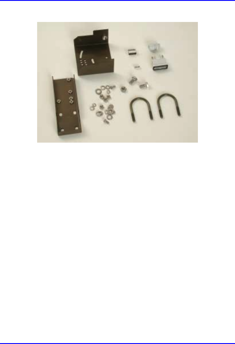
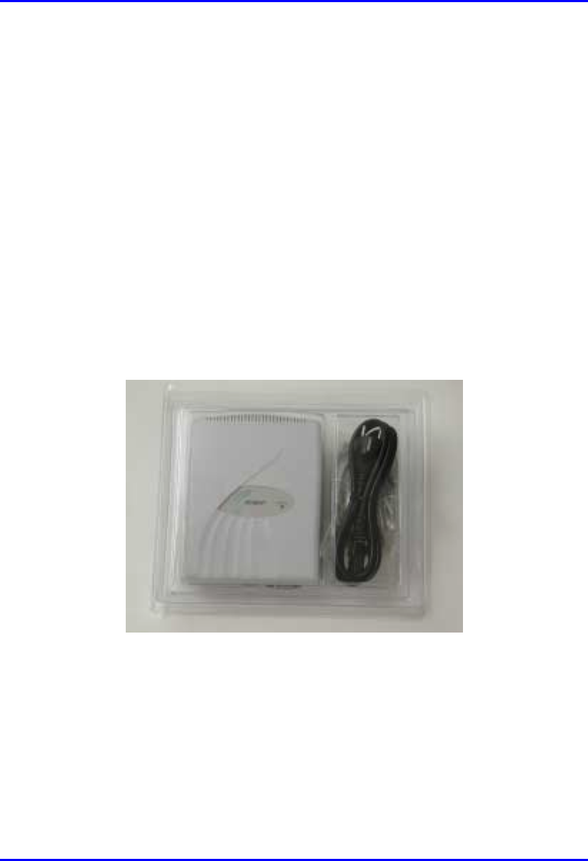
3.1.1.1. BSR
The BSR kit includes the following components:
! BSR chassis
! Mounting equipment that includes:
! Mounting brackets
! Mounting screws:
− Washers
− 4 x Screws
− Bolts
! Connectors:
! 15-Pin D-type (for data and serial interface, and power)
! N-type (optional for third-party external antenna)
Hardware Installation Manual Unpacking and Required Tools
02030311-03 Airspan Networks Ltd. 3-3
Figure 3-1: BSR kit
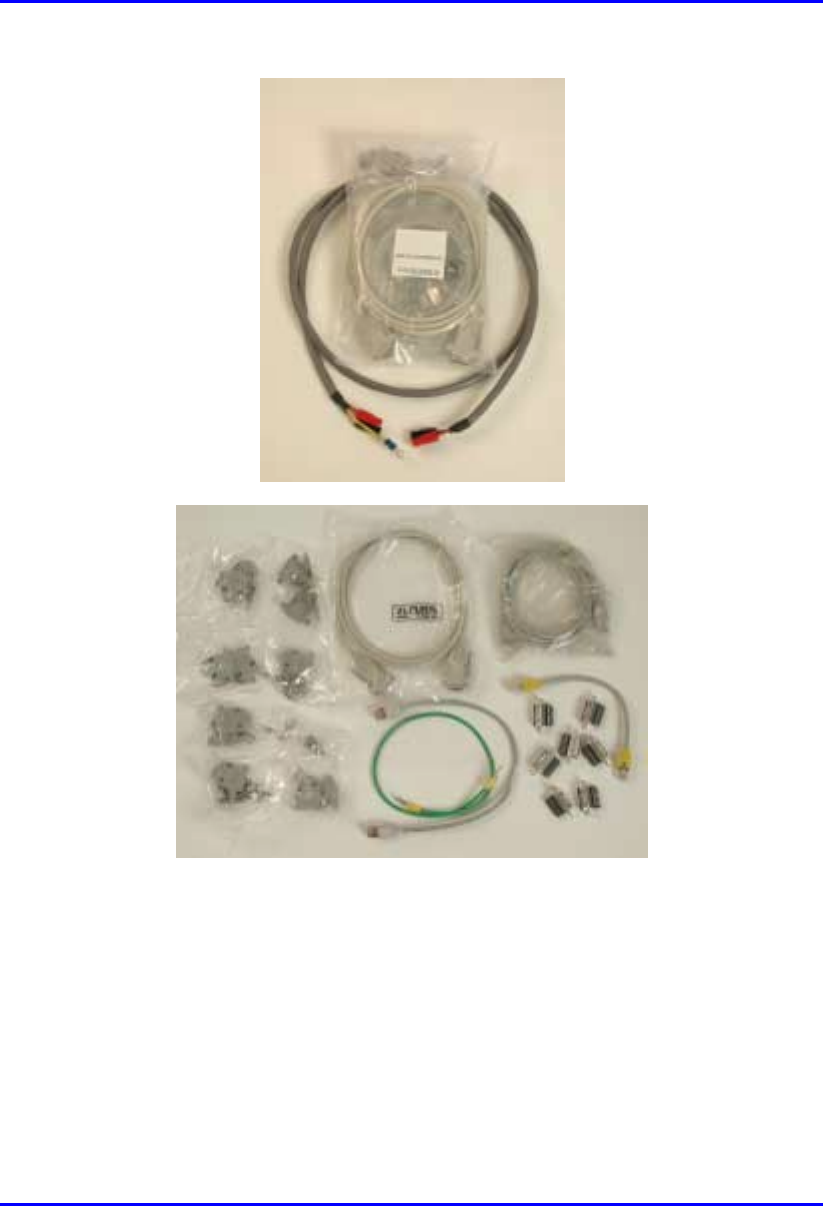
3.1.1.2. BSDU (optional)
The BSDU interfaces between the BSR and the backhaul network, as well as used
for daisy-chaining BSR units. The BSDU kit includes the following connectors:
! Mounting: four off M5 screws and plastic-cup washers
! 6 x RJ-45: two each for 100Base-T, 10Base-T, and clock synchronization
! 2 X 9-Pin D-type (for monitor and management)
! 7 x 15-Pin D-type (for power, Ethernet, daisy-chaining BSRs, and GPS)
! Power cable
Unpacking and Required Tools Hardware Installation Manual
3-4 Airspan Networks Ltd. 02030311-03
Figure 3-2: BSDU kit
Hardware Installation Manual Unpacking and Required Tools
02030311-03 Airspan Networks Ltd. 3-5
3.1.1.3. BSPS (optional)
The BSPS is an optional power redundancy unit (DC-UPS). The BSPS includes the
following parts:
! Rectifier
! DC Distribution
! System Controller
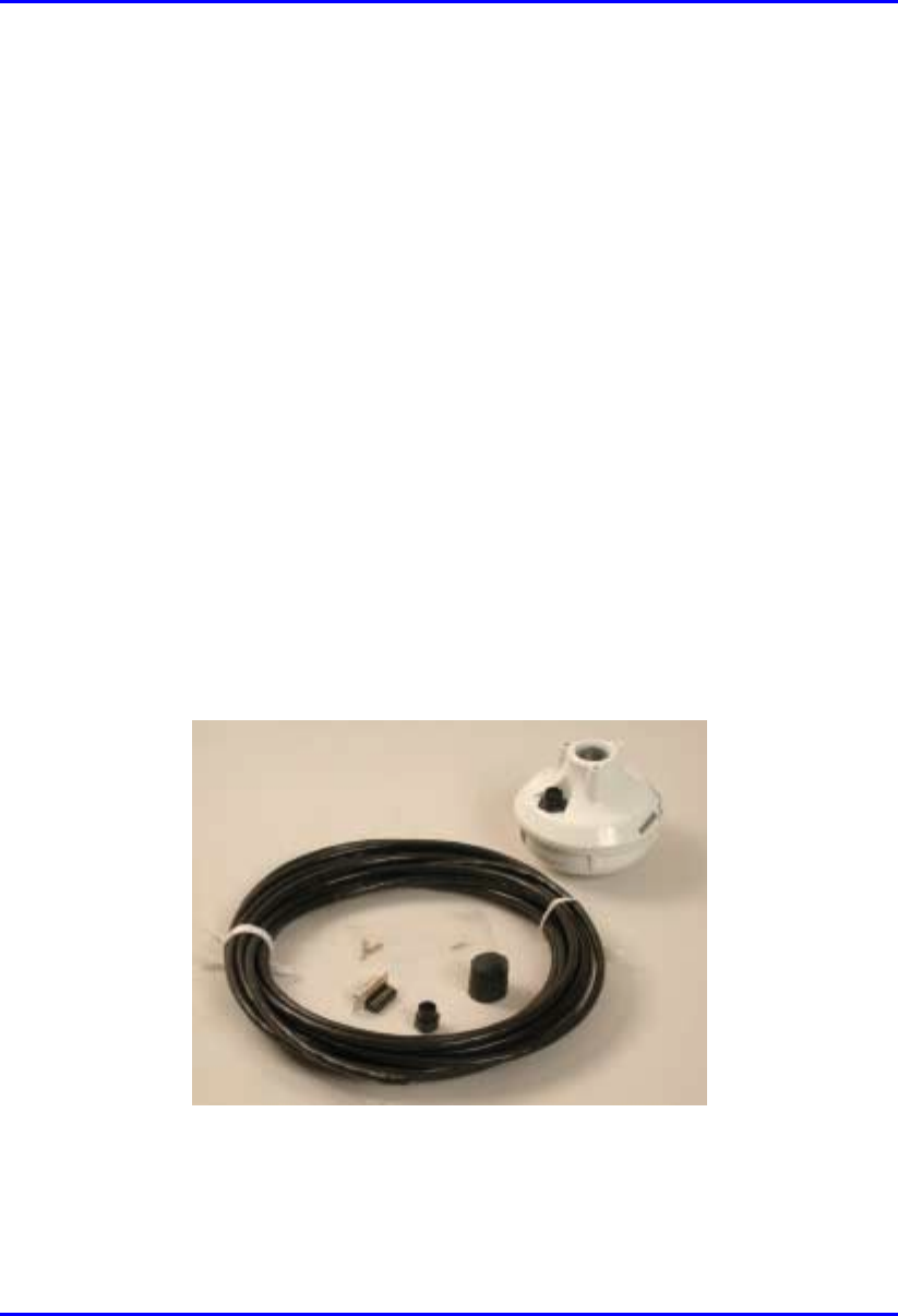
3.1.1.4. GPS (optional)
The GPS antenna synchronizes base stations by providing a universal satellite clock
signal.
! 5,15, or 50 meter mating cable
! 5/8″ adapter
! Magnet mount
Figure 3-3: GPS kit
Unpacking and Required Tools Hardware Installation Manual
3-6 Airspan Networks Ltd. 02030311-03
3.1.2. Customer Premises Equipment
WipLL hardware installed at the customer’s site includes the following:
! Subscriber Premises Radio (SPR)
! Subscriber Data Adapter (SDA)
! Indoor Unit (IDR)—optional, instead of the SPR and SDA
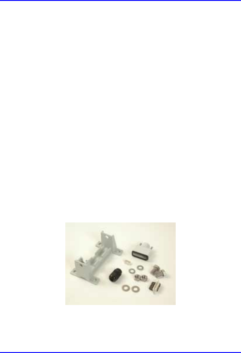
3.1.2.1. SPR
The SPR consists of the following parts:
! SPR chassis
! Mounting equipment that includes:
! Mounting bracket
! 2 x Screws
! 2 x Bolts
! 4 x Washers
! 15-Pin D-type connector
Figure 3-4: SPR kit
Hardware Installation Manual Unpacking and Required Tools
02030311-03 Airspan Networks Ltd. 3-7
3.1.2.2. SDA
The SDA is an Ethernet hub that connects to the main power supply and provides
data connection to the SPR. The SDA is available in two diffrenet modesl:
! SDA-1
! SDA-4H
3.1.2.2.1. SDA-1
The SDA-1 provides one 10Base-T connection to a host PC or network. The SDA-1
includes the following parts:
! SDA-1 chassis
! Power cable
Figure 3-5: SDA-1 kit
Unpacking and Required Tools Hardware Installation Manual
3-8 Airspan Networks Ltd. 02030311-03
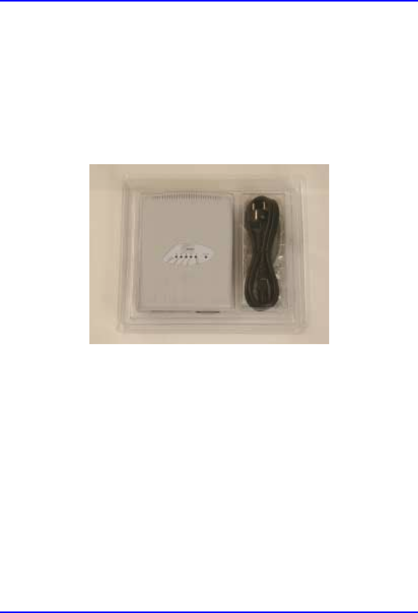
3.1.2.2.2. SDA-4H
The SDA-4H includes four interfaces: three for PC connection; one for daisy-
chaining to another hub or a LAN switch. The SDA-4H includes the following parts:
! SDA-4H chassis
! Power cable
Figure 3-6: SDA-4H kit
3.1.2.2.3. SDA-4S
The SDA-4S includes four 10/100Base-T interfaces for PC connection. The SDA-4S
kit includes the following parts:
! SDA-4S chassis
! Power cable

Hardware Installation Manual Unpacking and Required Tools
02030311-03 Airspan Networks Ltd. 3-9
Figure 3-7: SDA-4S kit TBD
3.1.2.3. IDR kit
The IDR unit is an optional customer premises equioment that replaces the SPR and
SDA. The IDR combines the SPR and SDA in one unit.
The IDR is available in two models: IDR with external antenna; IDR with internal
antenna. These two IDR models have the same parts, except that the IDR with
external antenna model has a connector for attaching a third-party antenna. The IDR
unit includes the following parts:
! Chassis
! Power cable
! Power supply unit
! Ethernet cable
! Mounting stand

Unpacking and Required Tools Hardware Installation Manual
3-10 Airspan Networks Ltd. 02030311-03
Figure 3-8: IDR kit

Hardware Installation Manual Unpacking and Required Tools
02030311-03 Airspan Networks Ltd. 3-11
3.2. Required Tools
The following tools are required for installing the WipLL system:
! Pin crimper tool for CAT-5e cables for 15-Pin D-type and N-type connectors,
and for GPS connectros
! Cable stripping tool
! Philips screw driver
! Flat-blade screwdriver
! Adjustable wrench
! ESD-prevention wrist strap
! Torque wrench for N-type connectors
! IDR unit:
! Flat blade screwdriver
! Pozidriv screwdriver
! 3 mm A/F Allen key
! 10 mm A/F open ended spanner

Part I
Part IPart I
Part I
Installing WipLL
Installing WipLL Installing WipLL
Installing WipLL
Base Station Equipment
Base Station EquipmentBase Station Equipment
Base Station Equipment
Part I describes the procedures for installing the WipLL base station equipment, and
includes the following chapters:
! Chapter 4, “Installing the Base Station Radio (BSR)”
! Chapter 5, “Installing the Base Station Distribution Unit (BSDU)”
! Chapter 6, “Installing the GPS”
! Chapter 7, “Installing the Base Station Power Supply (BSPS)”
This page is intentionally left balnk.

02030311-03 Airspan Networks Ltd. 4-1
Installing the BSR
Installing the BSRInstalling the BSR
Installing the BSR
This chapter describes the installation of the WipLL Base Station Radio (BSR) that
is installed at the base station.
This chapter includes the following sections:
! Overview
! Physical Dimensions
! Cable Installation Guidelines
! Connecting the BSR for Serial Configuration
! Connecting to the Backhaul Network and Power Supply
! Single BSR at a Base Station
! Multiple BSRs at a Base Station
! Conecting a Third-Party External Antenna (Optional)
! Mounting the BSR
! Attaching the Mounting Bracket
! Orientating the Mounted BSR
! Mounting the BSR on a Pole
4

Installing the BSR Hardware Installation Manual
4-2 Airspan Networks Ltd. 02030311-03
4.1. Overview
The BSR is the center of the WipLL system. The BSR provides last-mile wireless
connectivity by connecting the customer’s backhaul network to the subscriber’s
wireless unit (Subscriber Premises Radio [SPR]). In addition, the BSR is responsible
for synchronizing the WipLL network (i.e., synchronizing SPRs/IDRs).
For base stations consisting of only a single BSR, the BSR is typically powered and
connected to the customer’s backhaul by the WipLL Subscriber Data Adapter
(SDA). For base stations consisting of multiple BSRs, the BSRs are powered and
connected to the customer’s backhaul by the WipLL Base Station Distribution Unit
(BSDU).
The BSR is available in two models: BSR with an internal antenna providing 60°
sector coverage; and a BSR with an N-type port for connection to an optional third-
party external antenna.
Hardware Installation Manual Installing the BSR
02030311-03 Airspan Networks Ltd. 4-3
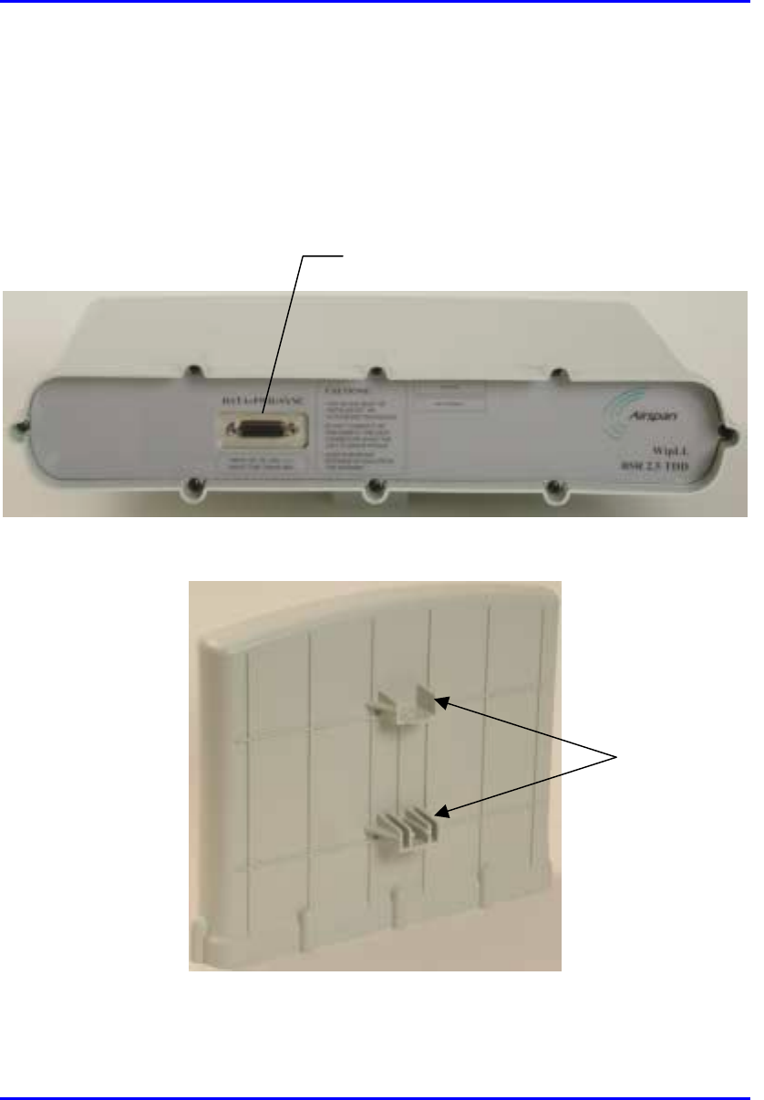
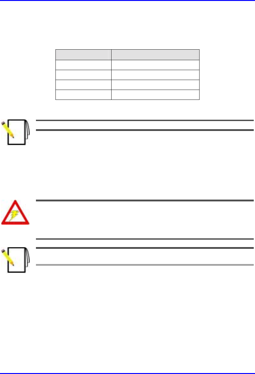
4.2. Physical Dimensions and Basic Design
The BSR is encased in a chassis providing access to the BSR’s communication port
at the front panel (see Figure 4-1). The BSR’s bottom panel provides holes for
mounting the BSR to, for example, a pole or wall (see Figure 4-2).
Figure 4-1: BSR front panel (internal antenna model)
Figure 4-2: BSR bottom panel providing holes for mounting
15-pin D-type port
Mounting holes
Installing the BSR Hardware Installation Manual
4-4 Airspan Networks Ltd. 02030311-03
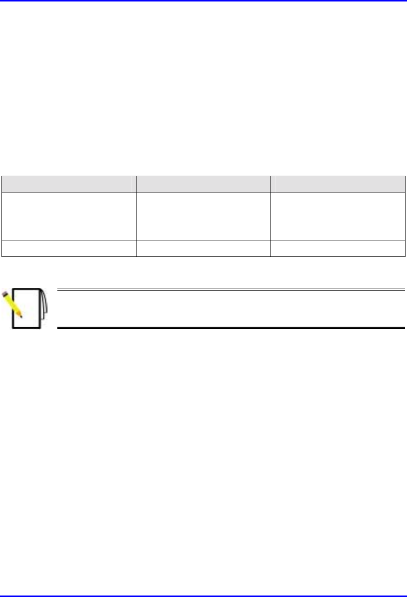
The BSR’s physical dimensions are described in Table 4-1
Table 4-1: BSR Physical Dimensions
Parameter Value
Height 400 mm (15.74 inches)
Width 317 mm (12.48 inches)
Depth 65.5 mm (2.58 inches)
Weight 4.7 kg
Note: The BSR’s physical dimensions exclude the mounting kit.
4.3. Cable Installation Guidelines
This section defines the procedures to be adhered to when installing data cables at
the base station.
Warning: Pre-terminated cables should be fitted with protective poly bags
during cable installation processes.
Metal cable trays shall be earthed to a central earth point within the customers’
equipment room.
Note: A minimum separation of 200 mm should exist between power and data
cables.
The following points are to be considered:
! When installing network cables, ensure that they are not damaged by friction or
sharp edges. Spacing of installation personnel at regular distances during any
cable drawing-in process will avoid contact with potential hazards.
! Data cables providing connection to the customers network shall be run in
suitable conduit or trunking. Cable trunking should be secured to the wall in
accordance with manufacturers instructions.

Hardware Installation Manual Installing the BSR
02030311-03 Airspan Networks Ltd. 4-5
! Cables should be carefully fed through trunking and not pulled by means of any
attached connector.
! Sufficient space should be provided in cable ducts, trunking or trays (where
possible) to allow for future cabling growth.
! External data cables are to be protected in protective conduit which is to be
secured to the building structure in accordance with manufacturers
recommendations. Trunking must not be located as to provide a trip hazard at the
base station premises (e.g. roof walkways)
! BSR cables are to be dressed tidily to the mounting pole or bracket using
strategically placed cable ties.
! Observe recommended minimum bend radii when installing copper cables.
Wherever a cable changes direction, ensure that it does so in a smooth curve
with a radius of at least 50mm in order to prevent damage.
! A maintenance loop is to be left in the cable just before the cable reaches the
BSR or GPS to prevent strain on the connector.
! Data cables entering holes drilled in walls are to be dressed to provide a loop that
will prevent water ingress into the building along the cable.
! Silicone sealant should be used to plug any holes on both internal and external
wall surfaces once cables are in place.
! All data cables should be labeled with both the source and destination at each
end.
Note: The maximum cable length between the BSR and terminating equipment
is 100 meters.
Installing the BSR Hardware Installation Manual
4-6 Airspan Networks Ltd. 02030311-03
4.4. Connecting the BSR for Serial
Configuration
The BSR’s 15-pin D-type port provides serial interface to a PC for BSR initial
configuration. This port uses 9 of its 15 pins for serial interface; the remaining pins
are used for interfacing with the BSDU or SDA with which the BSR is connected.
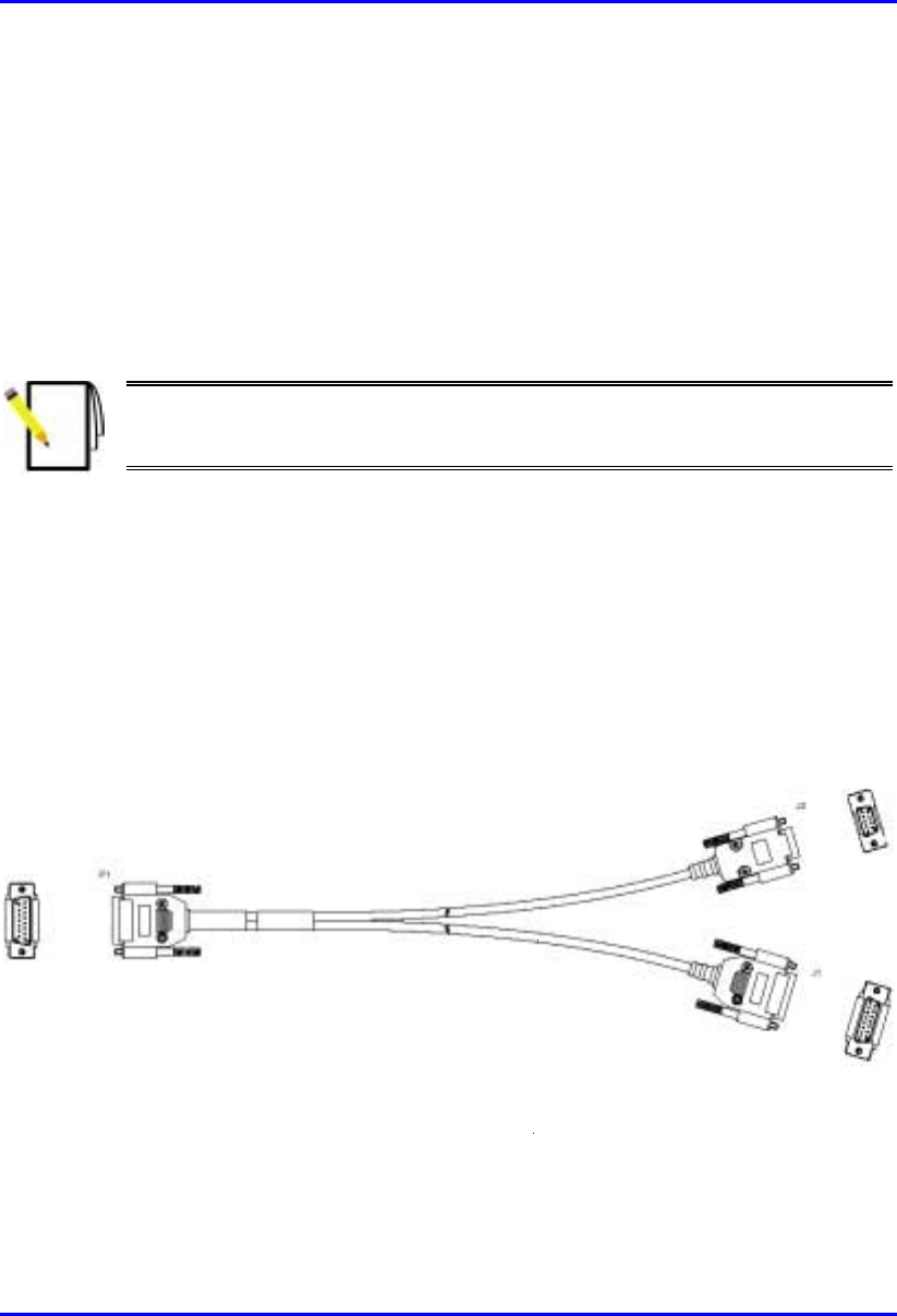
To connect the BSR to the PC and the SDA or BSDU, a Y-cable is used.
Note: For performing BSR initial configuration using WipLL’s management
applications, refer to WipConfig User’s Guide and WipConfig PDA User’s
Guide.
The BSR-to-PC management station serial cable connections include the following
! Connectors:
! BSR: 15-pin D-type male (only 9-pins used)
! PC: 9-pin D-type (RS-232)
! SDA/BSDU: 15-pin D-type male
! Cable: straight-through Y-cable
Figure 4-3: Y-Cable (P1 for BSR; J1 for SDA/BSDU; J2 for PC’s serial port)

Hardware Installation Manual Installing the BSR
02030311-03 Airspan Networks Ltd. 4-7
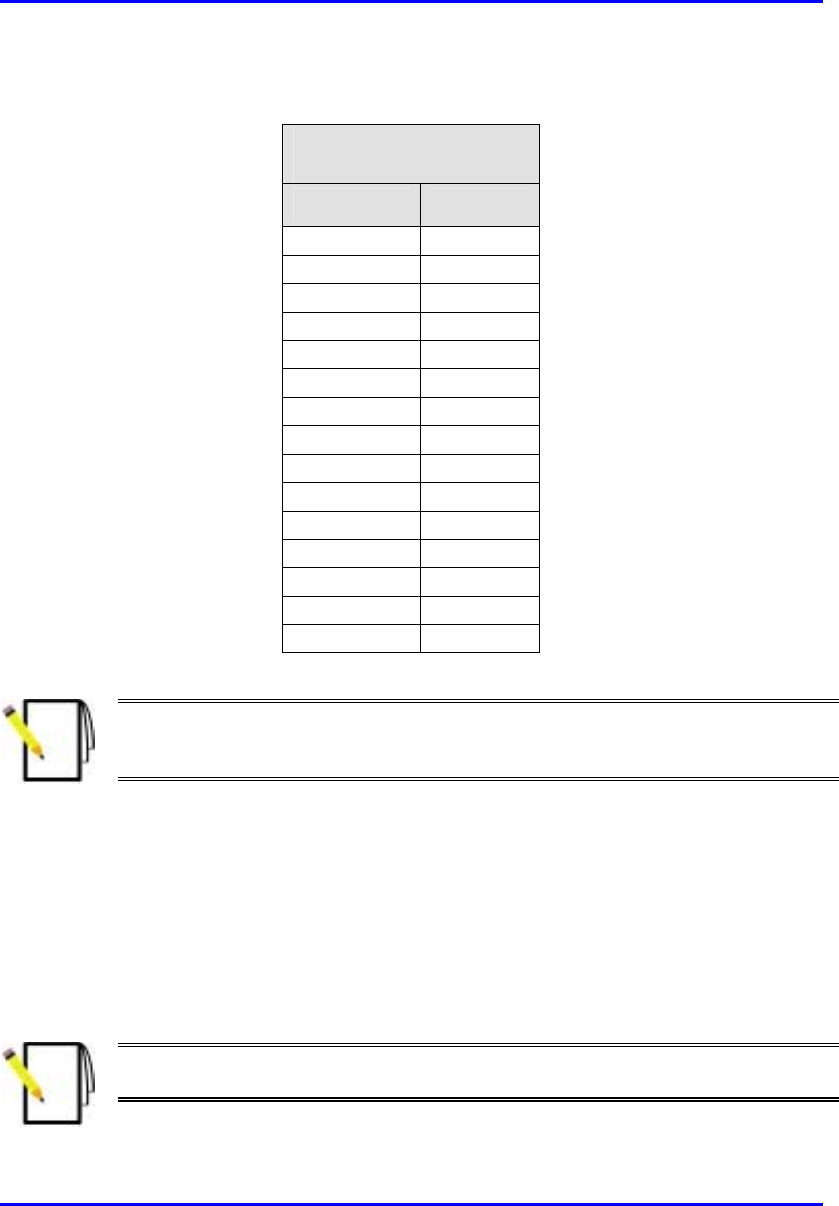
! Connector pinouts: Table 4-2 displays the connector pinouts for the 15-pin D-
type connectors at the BSR and SDA/BSDU, and the 9-pin D-type connector at
the PC management station.
Table 4-2: Y-cable connector pinouts for BSR serial cable connection
SPR (15-pin D Type)
P1
SDA (15-pin D Type)
J1
PC (RS-232)
J2
Pin Function Pin 9-Pin Function
1 0 VDC 1 0 VDC 1
2 +48 VDC 2 +48 VDC 2 Tx
3 Ethernet Tx+ 3 Ethernet Tx+ 3 Rx
4 Ethernet Tx- 4 Ethernet Tx- 4
5 Ethernet Rx+ 5 Ethernet Rx+ 5 GND
6 Ethernet Rx- 6 Ethernet Rx- 6
7 Ho
p
S
y
nc+ 7 Ho
p
S
y
nc+ 7
8 Ho
p
S
y
nc- 8 Ho
p
S
y
nc- 8
9
N
C 9
N
C9
10
N
C 10
N
C
11
N
C 11
N
C
12
N
C 12
N
C
13
N
C 13
N
C
14 RS232 Rx 14
N
C
15 RS232 Tx 15
N
C
Installing the BSR Hardware Installation Manual
4-8 Airspan Networks Ltd. 02030311-03
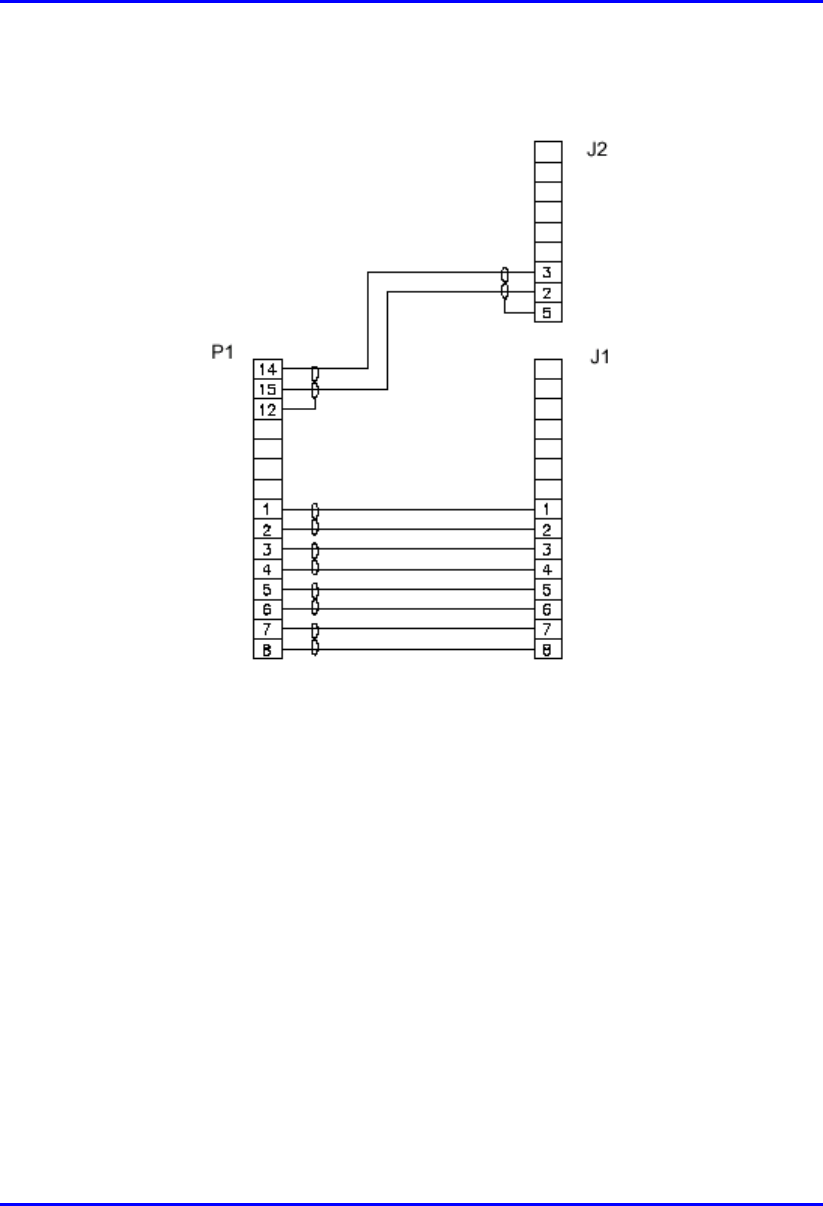
The Y-cable connector pin assignments is displayed in Figure 4-4.
Figure 4-4: Y-cable connector pin assignment
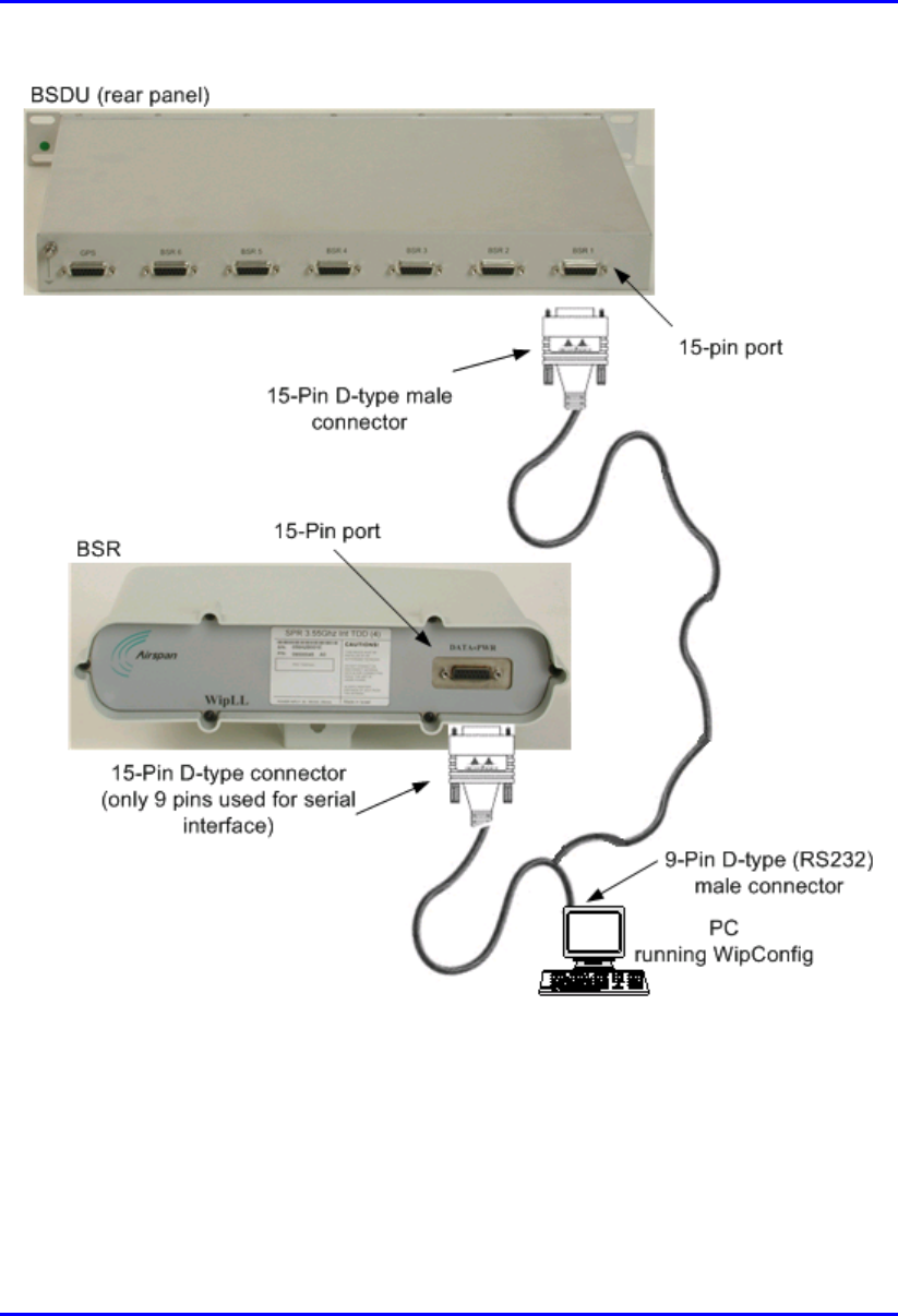
To connect the BSR to the PC and SDA/BSDU for serial configuration:
1. Connect the 15-pin D-type male connector, at the one end of the Y-cable, to the
BSR, as displayed in Figure 4-5.
2. Connect the 15-pin D-type male connector, at the other end of the Y-cable, to
the SDA or BSDU, as displayed in Figure 4-5.
3. Connect the 9-pin D-type (RS232) connector, at the other end of the Y-cable, to
the PC, as displayed in Figure 4-5.
Hardware Installation Manual Installing the BSR
02030311-03 Airspan Networks Ltd. 4-9
Figure 4-5: PC-to-BSR Serial Connection using Y-shaped Cable

Installing the BSR Hardware Installation Manual
4-10 Airspan Networks Ltd. 02030311-03
4.5. Connecting BSR to the Backhaul Network
The BSR connection to the customer’s backhaul network depends on the base
station’s configuration:
! For base stations consisting of single BSRs, the connection to the backhaul is
through the SDA
! For base stations consisting of multiple BSRs, the connection to the backhaul is
through the BSDU.
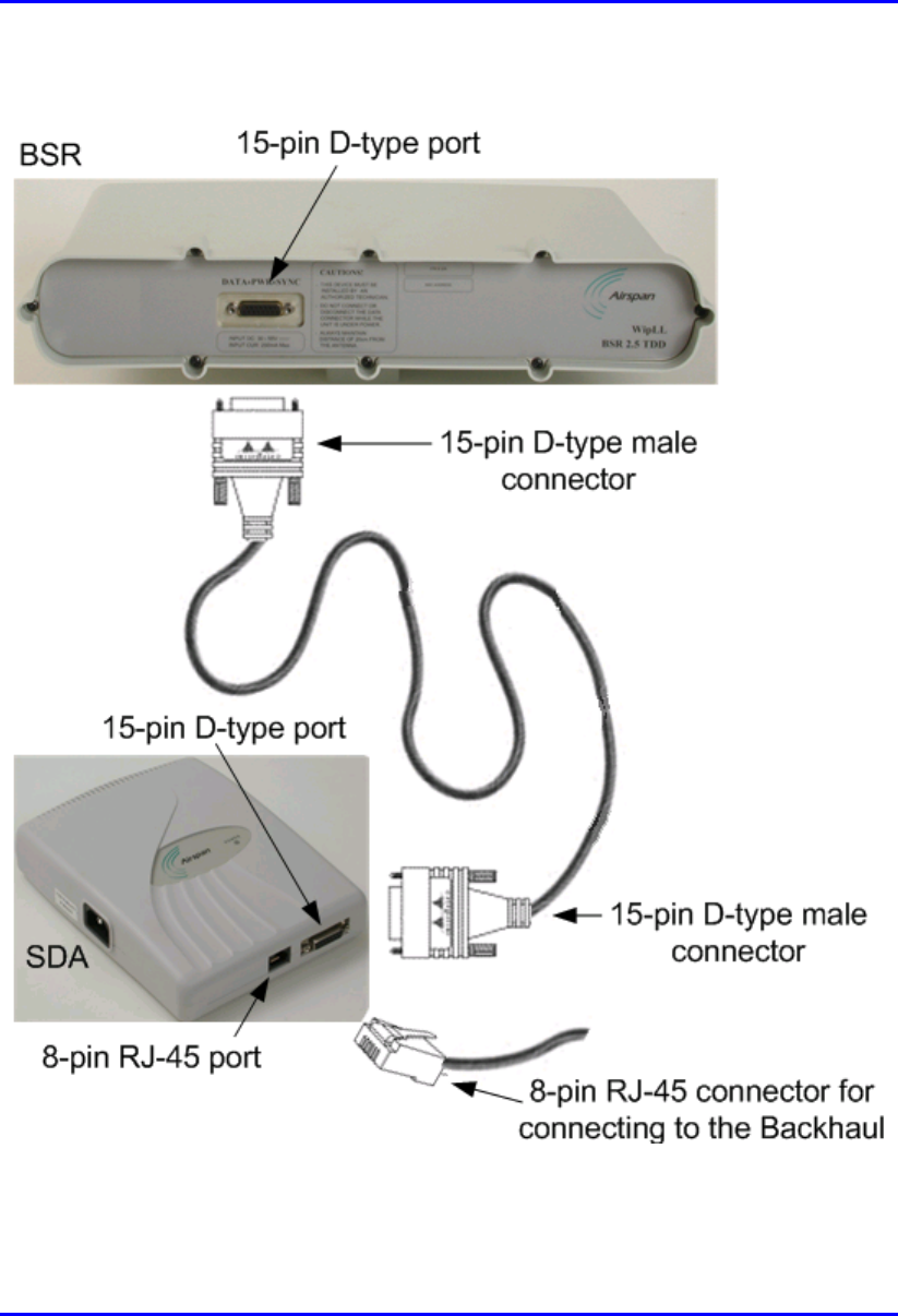
4.5.1. Through the SDA
For a base station consisting of a single BSR, the BSR’s power supply and
connectivity to the backhaul network is provided by the SDA. The SDA is typically
installed at the subscriber’s premises, but in such a scenario, the SDA can also be
used at the base station. For a detailed description of the SDA, see Chapter 8,
“Installing the SPR and SDA”.
The BSR-to-SDA cable connection configurations is as follows:
! Connectors:
! BSR: 15-pin D-type male (only 8 pins are used)
! SDA: 15-pin D-type male (only 8 pins are used)
! Cable: straight-through CAT-5

Hardware Installation Manual Installing the BSR
02030311-03 Airspan Networks Ltd. 4-11
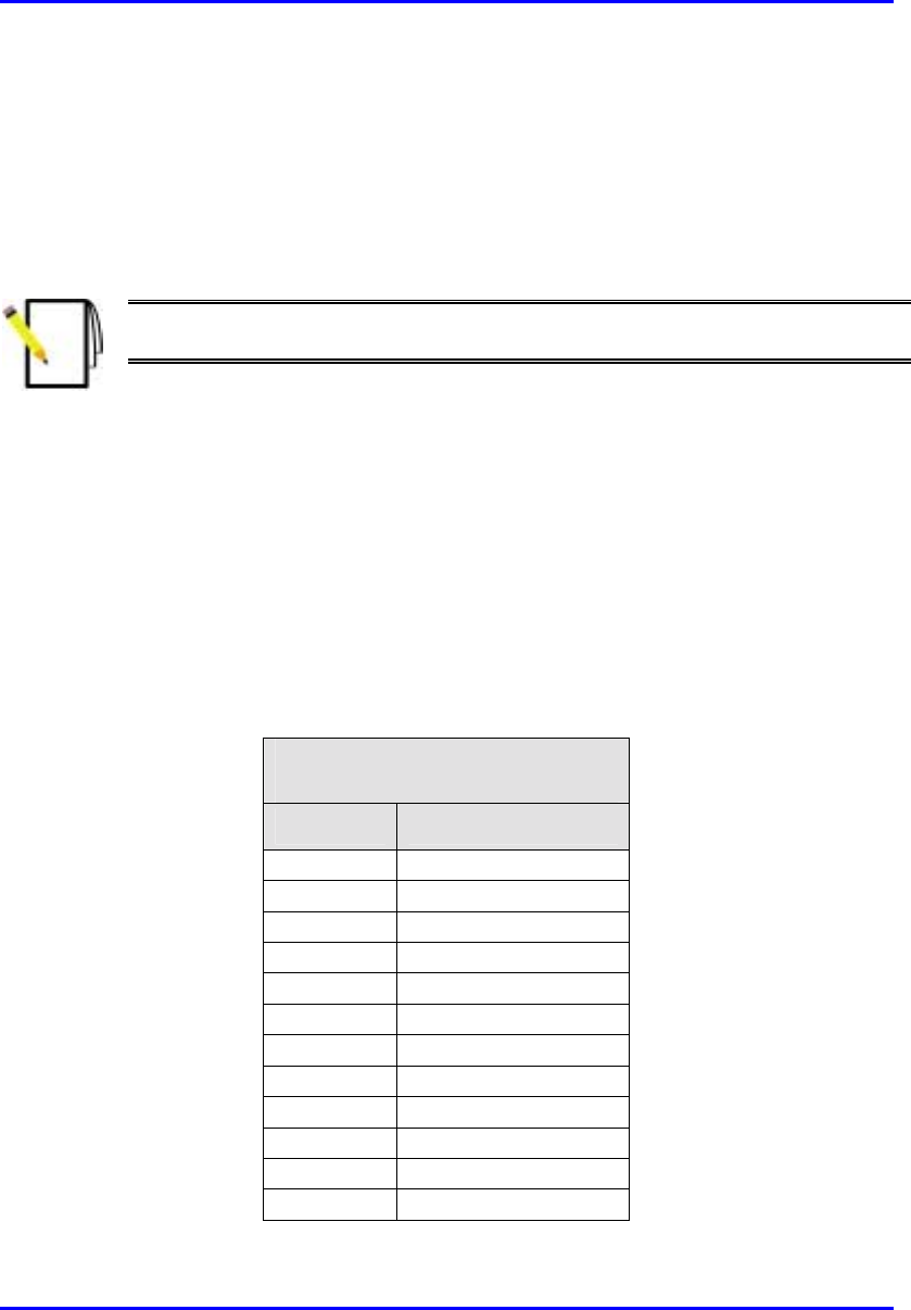
! Connector pinouts:
! BSR:
BSR
(15-Pin D-type)
Pin Function
1 + 48VDC
2 - 48VDC
3 +Tx
4 -Tx
5 +Rx
6 -Rx
7 +S
y
nc.
8 -S
y
nc.
9
N
ot connected
(
NC
)
10
N
C
11 NC
12 NC
13 NC
14 NC
15 NC
Installing the BSR Hardware Installation Manual
4-12 Airspan Networks Ltd. 02030311-03
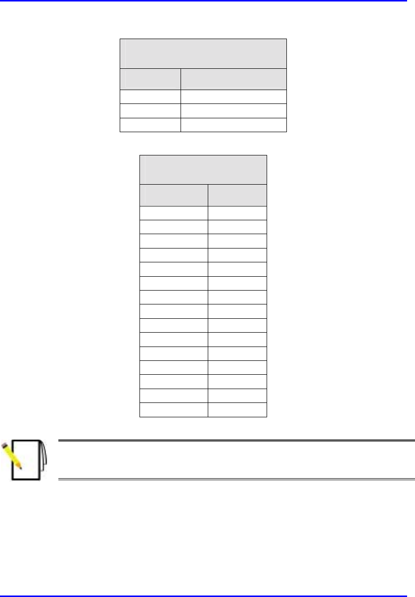
! SDA models (SDA-1, SDA-4H, and SDA-4S):
SDA
(15 Pin D-type)
Pin Function
1 +48VDC
2 -48VDC
3 +RX
4
–
RX
5 +TX
6
–
TX
7
N
C
8
N
C
9
N
C
10
N
C
11
N
C
12
N
C
13
N
C
14
N
C
15
N
C
Note: Airspan supplies unterminated cables for 15-Pin D-type connectors. Refe
r
to the cable crimping procedures for 15-Pin D-type connectors detailed in
Appendix B, “Cable Crimping".
To connect the BSR to the backhaul through the SDA:
1. Attach the 15-pin D-type connector, at one end of the cable, to the BSR’s 15-pin
D-type port labeled DATA POWER SYNC, as displayed in Figure 4-6.
2. Attach the 15-pin D-type connector, at the other end of the cable, to the SDA’s
15-pin D-type port, as displayed in Figure 4-6.
3. Connect the SDA’s RJ-45 Ethernet port to the backhaul.
Note: SDA is available in six models. For a detailed description of the SD
A
models, see Chapter 8, “Installing the SPR and SDA”.
Hardware Installation Manual Installing the BSR
02030311-03 Airspan Networks Ltd. 4-13
Figure 4-6: Connecting BSR to the backhaul through the SDA
Installing the BSR Hardware Installation Manual
4-14 Airspan Networks Ltd. 02030311-03
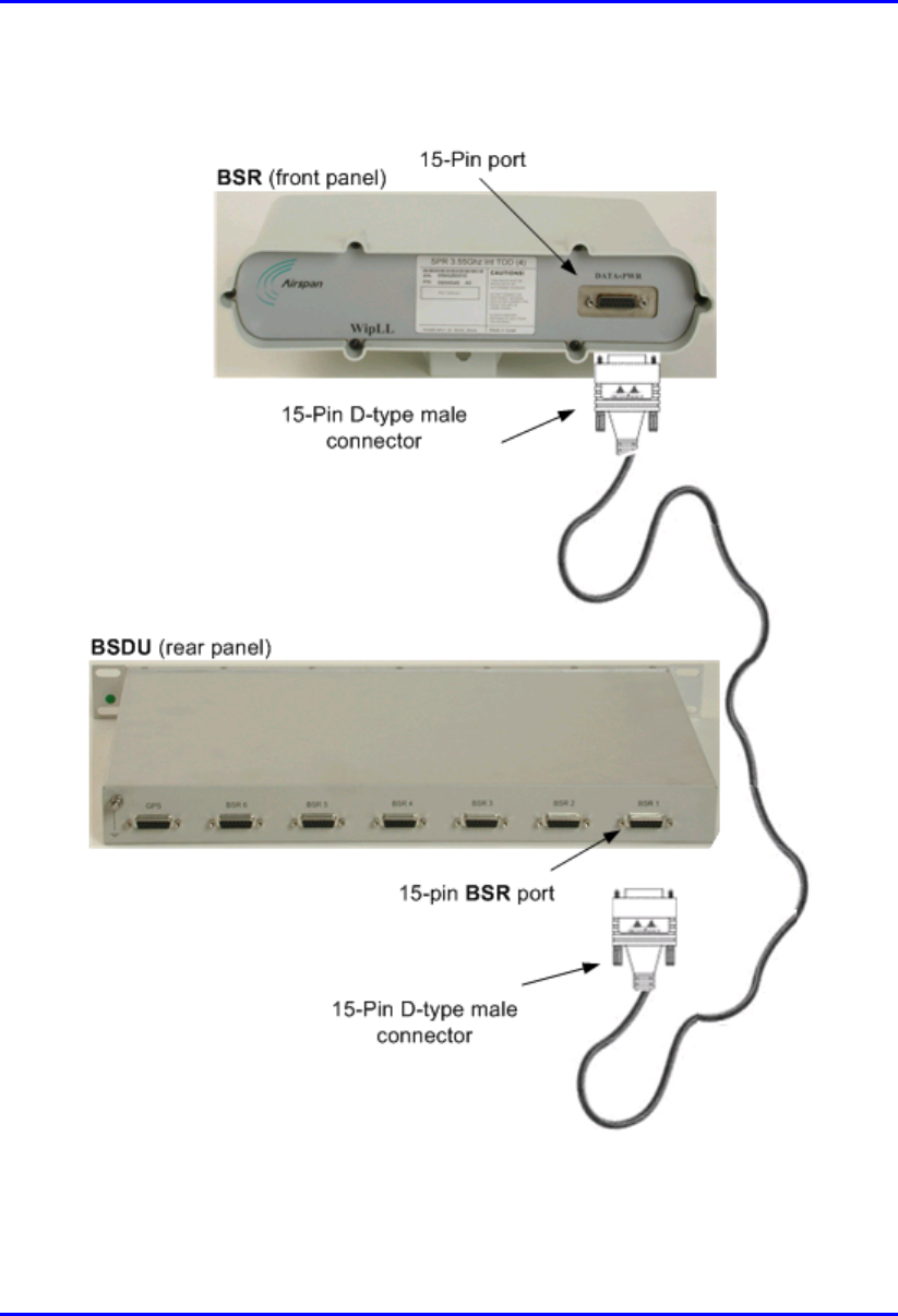
4.5.2. Through the BSDU
For base stations consisting of multiple BSRs, the power supply and connectivity to
the backhaul network is provided by the BSDU. The BSR’s 15-pin D-type port is
connected to the BSDU’s rear panel 15-pin D-type port (labeled BSR #).
Note: For a detailed description of the BSDU, see Chapter 5, “Installing the
BSDU”.
The BSR-to-BSDU cable connection configurations is as follows:
! Connector:
! BSR: 15-pin D-type male (only 8 pins are used)
! BSDU: 15-pin D-type male (only 8 pins are used)
! Cable: straight-through 10Base-T Ethernet 4 Pair Cat 5 outdoor type – 24 AWG
! Connector pinouts:
! BSR:
BSR
(15-pin D-type)
Pin Function
1 + 48VDC
2 - 48VDC
3 +Tx
4 -Tx
5 +Rx
6 -Rx
7 +S
y
nc.
8 -S
y
nc.
9
N
ot connected
(
NC
)
10
N
C
11 NC
12 NC
Hardware Installation Manual Installing the BSR
02030311-03 Airspan Networks Ltd. 4-15
BSR
(15-pin D-type)
Pin Function
13 NC
14 NC
15 NC
! BSDU:
BSDU
(15-pin D-type)
Pin Function
1 +48VDC
2 -48VDC
3 +RX
4
–
RX
5 +TX
6
–
TX
7
N
C
8
N
C
9
N
C
10
N
C
11
N
C
12
N
C
13
N
C
14
N
C
15
N
C
Note: Airspan supplies unterminated cables for 15-Pin D-type connectors. Refe
r
to the cable crimping procedures for 15-Pin D-type connectors detailed in
Appendix B, “Cable Crimping".

Installing the BSR Hardware Installation Manual
4-16 Airspan Networks Ltd. 02030311-03
To connect the BSR to the backhaul through the BSDU:
1. Attach the 15-pin D-type connector, at one end of the cable, to the BSR’s 15-pin
D-type port labeled DATA POWER SYNC, as displayed in Figure 4-7.
2. Attach the 15-pin D-type connector, at the other end of the CAT-5 cable, to the
BSDU’s 15-pin D-type port labeled BSR, located at the rear of the BSDU, as
displayed in Figure 4-7.
3. Connect one of the BSDU’s 100Base-T ports, located at the front panel, to the
backhaul (see Chapter 5, “Installing the BSDU” for a detailed description of
connecting the BSDU to the backhaul).
Hardware Installation Manual Installing the BSR
02030311-03 Airspan Networks Ltd. 4-17
Figure 4-7 displays the cable connections between the BSR and BSDU.
Figure 4-7: BSR-to-BSDU cable connection
Installing the BSR Hardware Installation Manual
4-18 Airspan Networks Ltd. 02030311-03
4.6. Conecting a Third-Party External Antenna
(Optional)
The BSR model with an N-type connector can be connected to an external antenna
(see Figure 4-9). The addition of an external antenna allows greater RF sector
coverage than the standard BSR Internal Antenna model (i.e., 60°). The BSR with
an external antenna is especially suited for base stations with one BSR, where sector
coverage can be increased to 360° by using an omni-antenna.
! Connector: N-type male
Figure 4-8: Example of an N-type connector
! Cable: RF
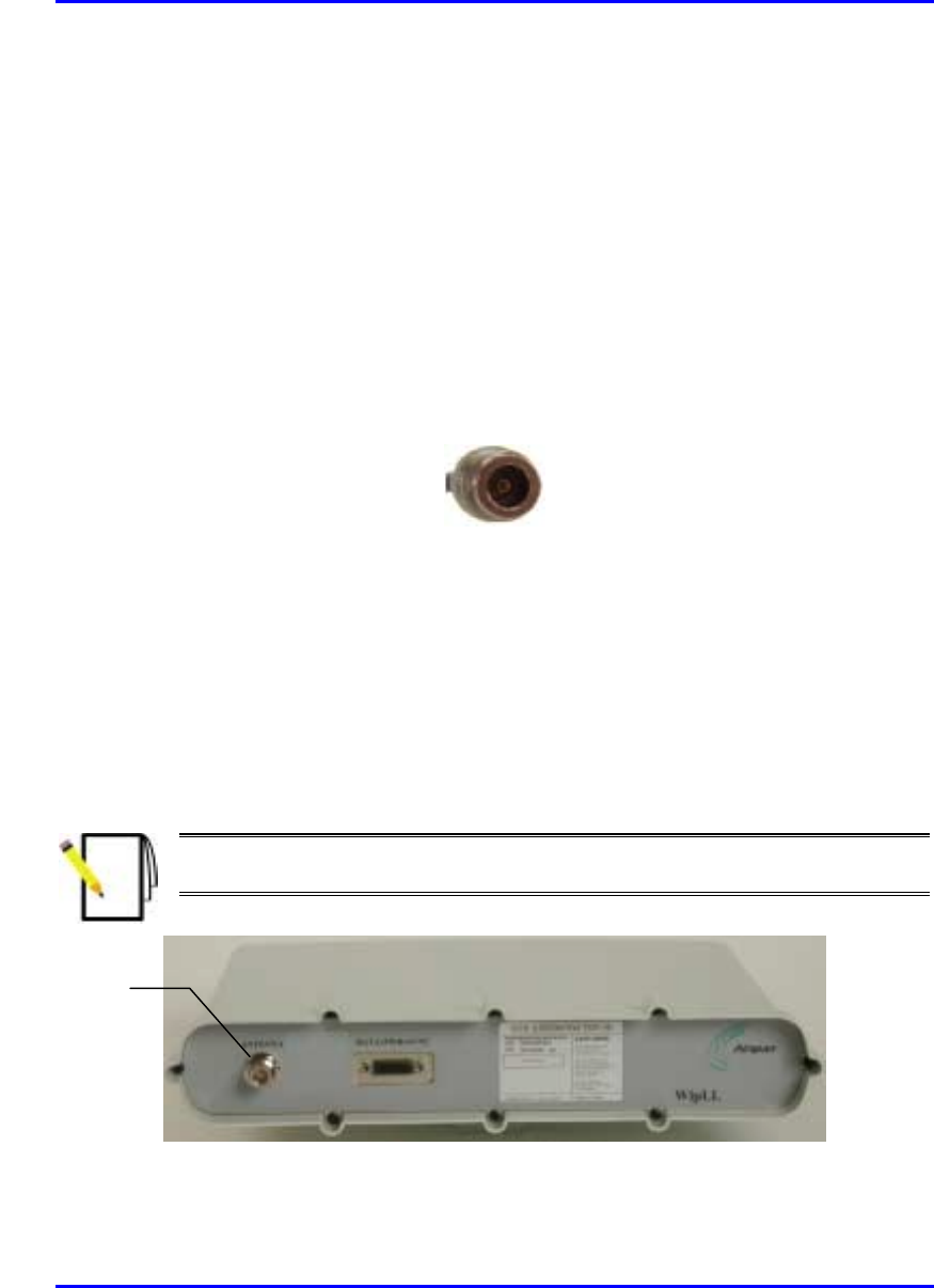
To connect the BSR to an external antenna:
1. Attach the N-type male connector to the N-type receptacle located on the BSR’s
front panel.
2. Attach the other end of the cable to the external antenna.
Note: For crimping cables for N-type connectors, see Appendix B, “Cable
Crimping”.
Figure 4-9: BSR model with N-type antenna connector
N
-type
antenna
connector
Hardware Installation Manual Installing the BSR
02030311-03 Airspan Networks Ltd. 4-19
4.7. Connecting the BSR to Power
The BSR is powered by the SDA or BSDU (depending to which unit the BSR is
connected). The power is supplied through the BSR’s 15-pin D-type port, which is
connected to the SDA or BSDU.
The BSR’s power requirements are described in Table 4-3.
Table 4-3: BSR Power Requirements
Parameter Value Comment
Voltage:
• Minimum
• Maximum
48 VDC nominal
• 30 VDC
• 55 VDC
Voltage is received from the
BSDU or SDA
Maximum Amperes: 500 mA
Note: For details on connecting the SDA or BSDU to the mains power supply,
see Chapter 5, “Installing the BSDU” and Chapter 8, “Installing the SPR and
SDA”.
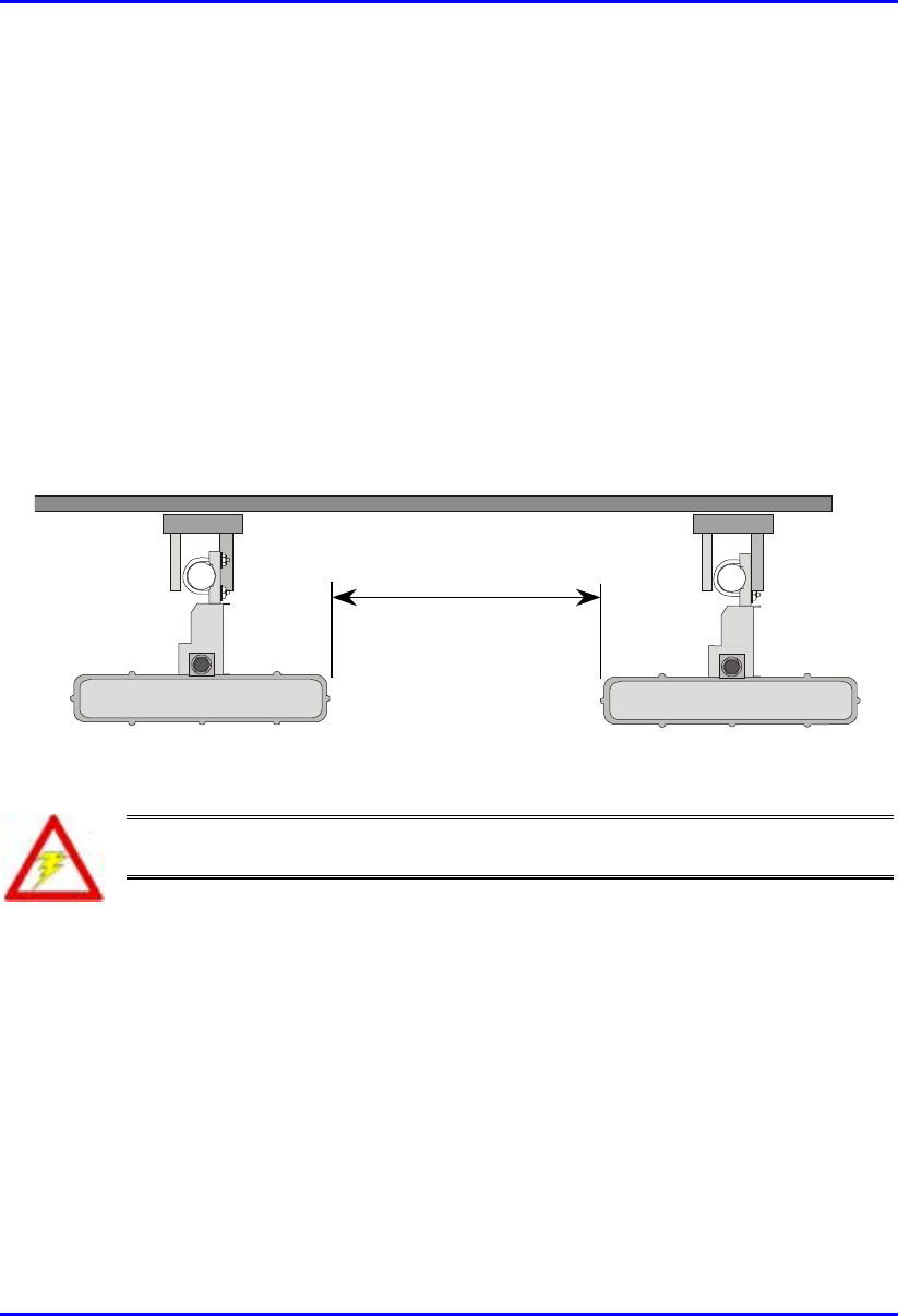
Installing the BSR Hardware Installation Manual
4-20 Airspan Networks Ltd. 02030311-03
4.8. Mounting the BSR
The BSR can be mounted on a wall or pole (see Figure 4-14). The BSR is mounted
using the mounting holes located on the BSR’s bottom panel, and the mounting
bracket (provided by Airspan). The mounting brackets for BSR wall- and pole-
mounting are different.
4.8.1. Minimum Distance Between BSRs
To prevent system interference, each BSR requires a minimum of 1-metre separation
between adjacent BSRs (see Figure 4-10).
1 Metre min.
Figure 4-10: Minimum distance between mounted BSRs
Warning: The BSR emits microwave radiation; a minimum distance of 250
mm must be maintained from the front of the BSR.
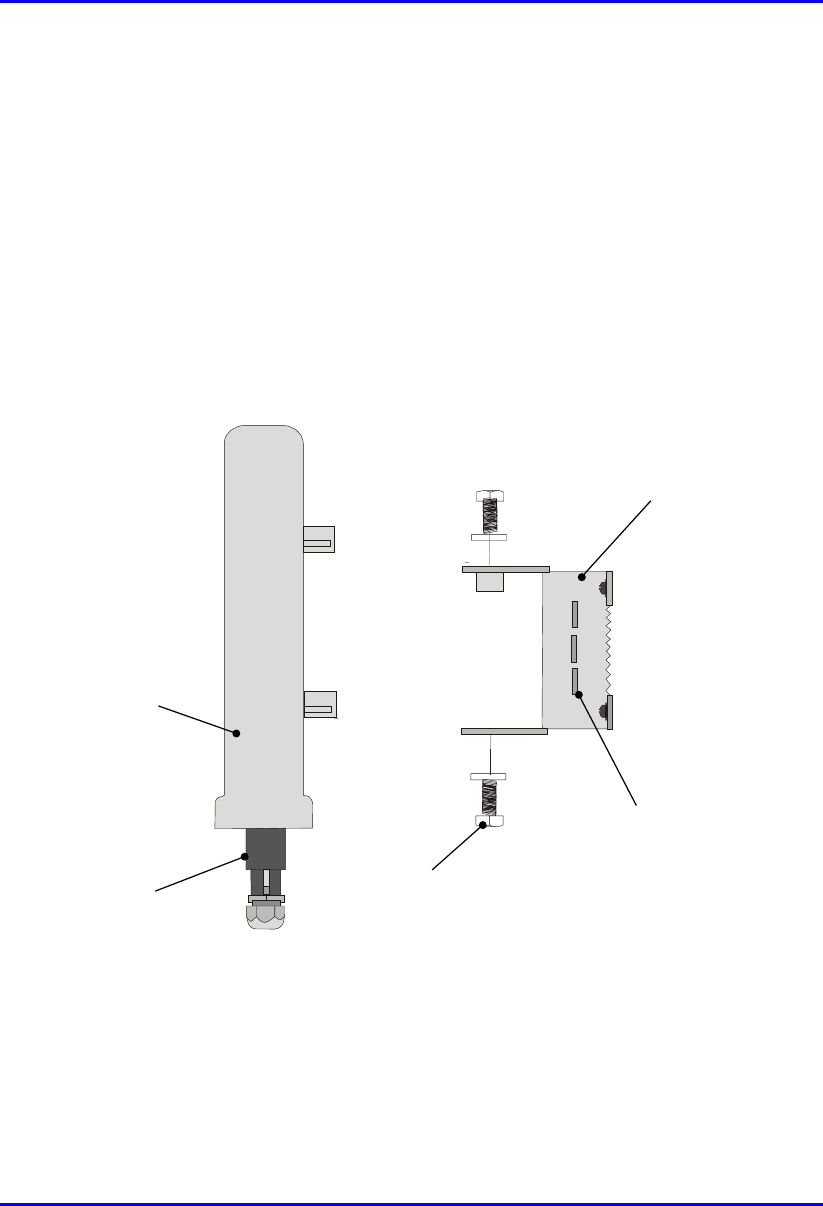
Hardware Installation Manual Installing the BSR
02030311-03 Airspan Networks Ltd. 4-21
4.8.2. Wall Mounting
BSR wall mounting is performed in two chronological stages:
! Attaching the mounting bracket to the BSR’s mounting holes.
! Attaching the mounting bracket (attached to the BSR) to the wall.
To mount the BSR on a wall:
1. Attach the mounting bracket to the BSR using two stainless steel bolts, as shown
in Figure 4-11.
Jubilee clip slots
BSR
BSR Fixing Bolts
BSR Mounting
Bracket
15-pin D-type
connector
Figure 4-11: Attaching the mounting bracket to the BSR
2. Attach the mounting bracket to the wall using four screws. The fixing
dimensions for the mounting bracket is illustrated in Figure 4-12
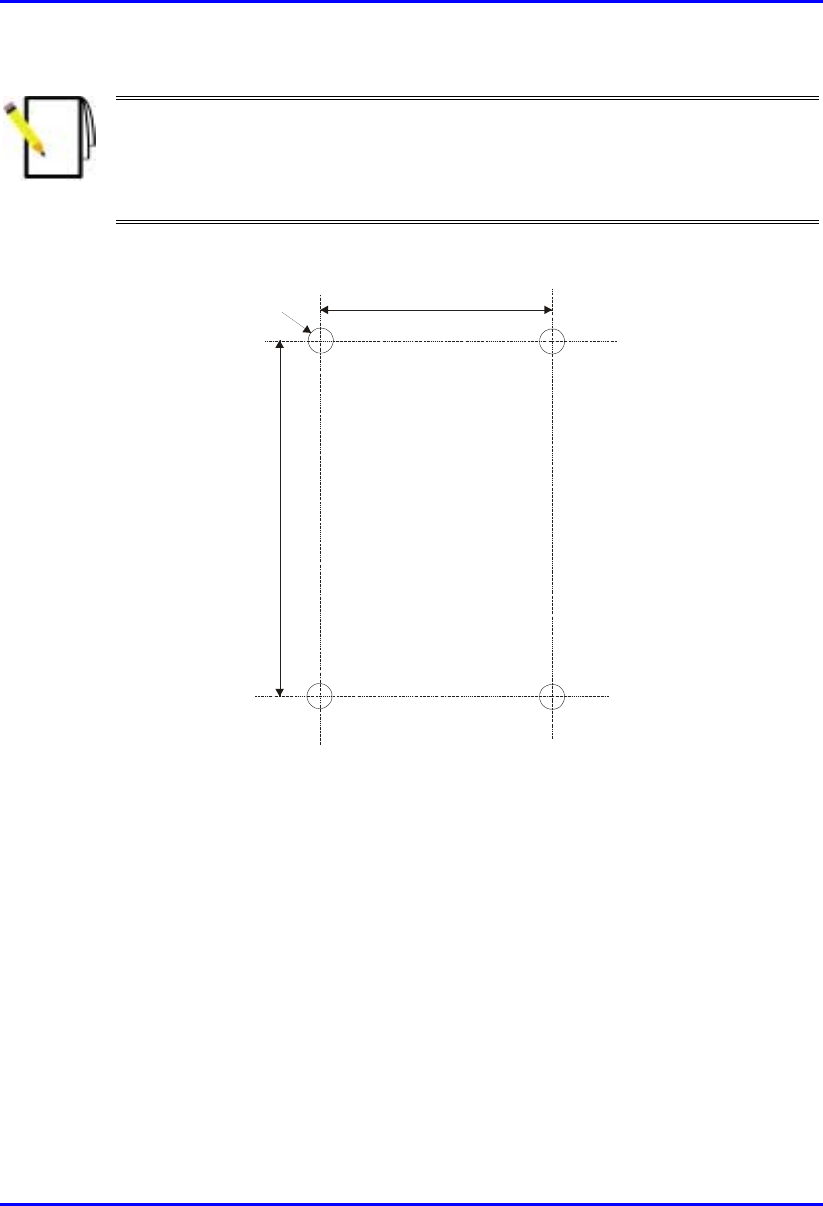
Installing the BSR Hardware Installation Manual
4-22 Airspan Networks Ltd. 02030311-03
Note: Airspan does not provide screws for attaching the mounting bracket to
the wall. The screw size depends on the structure of the building to which the
bracket is to be attached. When selecting screw sizes, consideration must be
given to the weight of the BSR and load that may be induced in windy
conditions.
.
58mm
8mm
99mm
Figure 4-12: BSR mounting bracket dimensions for the four fixing holes
3. Adjust the horizontal positioning of the BSR, and then fasten tight the two
stainless-steel bolts.
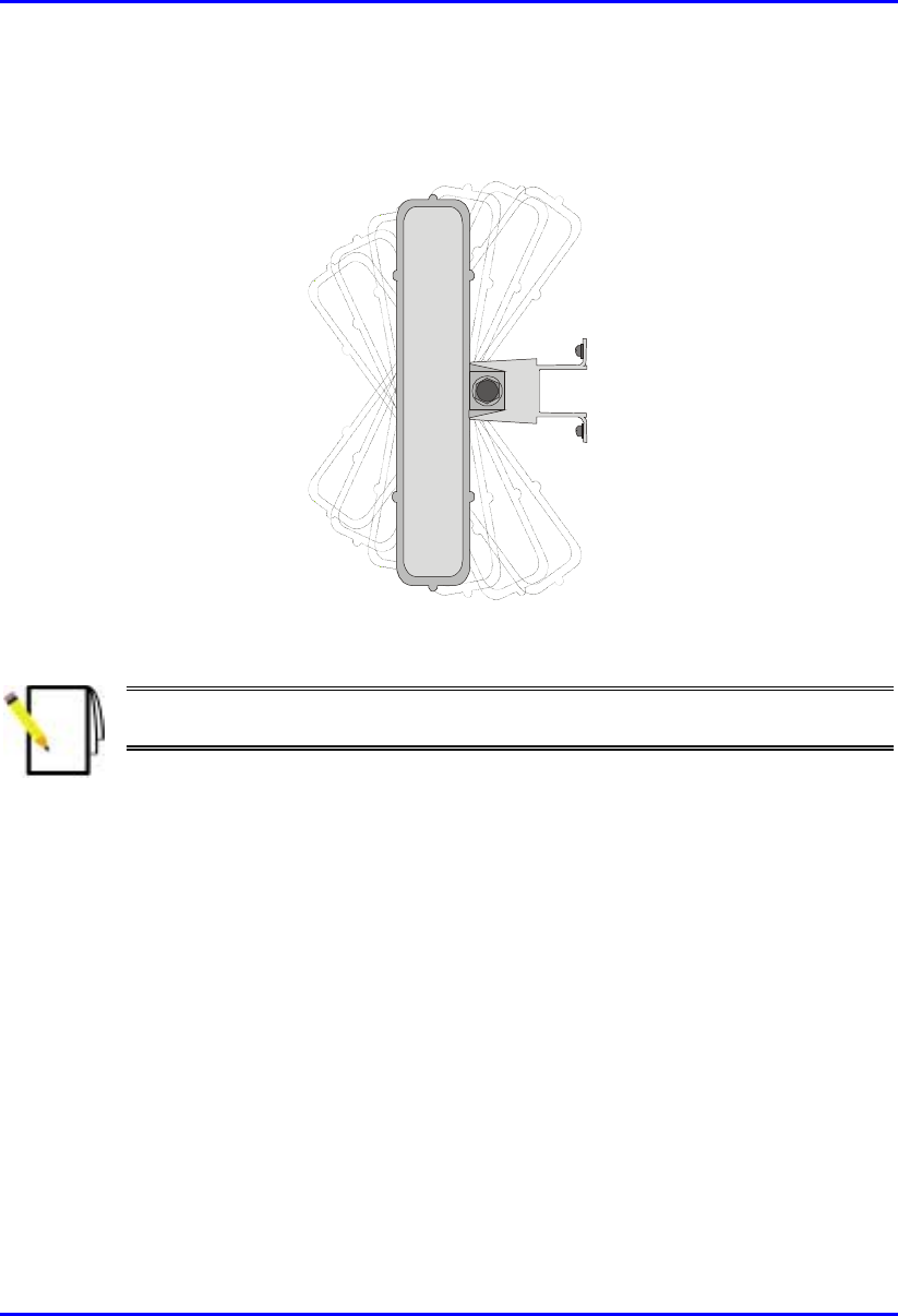
Hardware Installation Manual Installing the BSR
02030311-03 Airspan Networks Ltd. 4-23
Rotation is restricted to the horizontal plane only. The permissible rotation is
shown in Figure 4-13.
Figure 4-13: Horizontal rotation of the BSR
Note: A thread-locking compound is to be used to prevent the bolts working
loose.
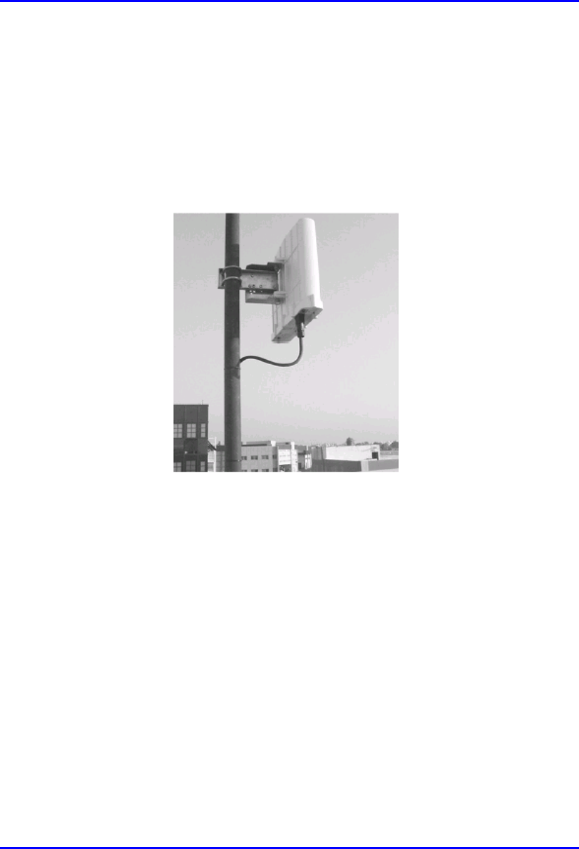
Installing the BSR Hardware Installation Manual
4-24 Airspan Networks Ltd. 02030311-03
4.8.3. Pole Mounting
The BSR can be mounted on a pole (see Figure 4-14). Pole mounting allows the
BSR to be adjusted in the horizontal as well as the vertical plane. The pole-mounting
bracket assembly is designed to support the BSR on a round pole of 45 mm in
diameter.
Figure 4-14: Mounted BSR

Hardware Installation Manual Installing the BSR
02030311-03 Airspan Networks Ltd. 4-25
To mount the BSR on a pole:
1. Attach the mounting bracket to the BSR using two stainless steel bolts.
Pivot Hole
‘U’ Bolt
Locking Holes
BSR mounting
Bracket
Clamping Bracket
Figure 4-15: BSR mounting bracket assembly
2. Attach the clamping bracket to the mounting bracket using two M8 stainless
bolts.
3. Attach the Clamping bracket to the pole by placing the U-bolt around the pole,
and then inserting the U-bolt through the Clamping bracket and securing it by
screwing the two bolts on the U-bolt.
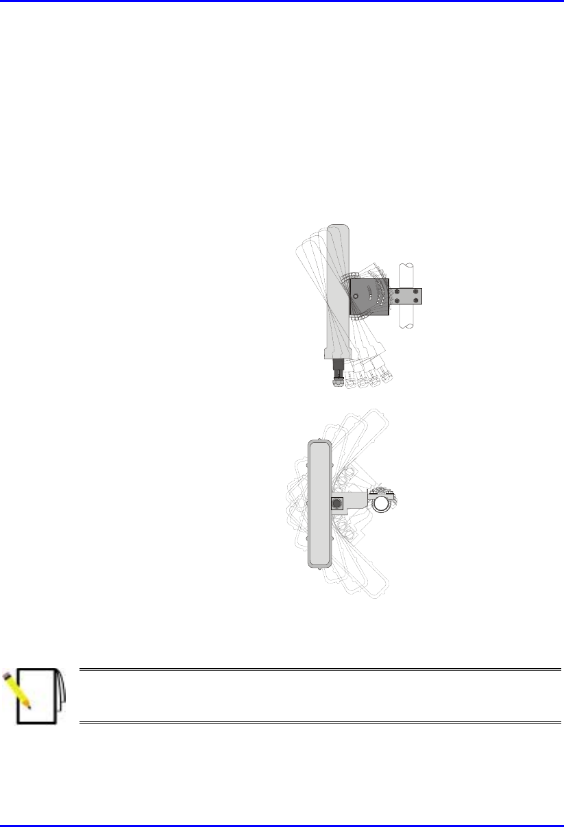
Installing the BSR Hardware Installation Manual
4-26 Airspan Networks Ltd. 02030311-03
4. Adjust the vertical position of the BSR. Lock the BSR at the desired position by
inserting the locking bolt in the desired position. Once the correct angle has been
set both bolts must be tightened to lock the BSR bracket in place.
5. Adjust the horizontal position of the BSR by rotating the BSR about the pole,
and then tighten the U-bolt.
BSR positioning is obtained in two planes by adjustment of the mounting
bracket assembly a shown in Figure 4-16.
Rotation about the
mounting pole
Rotation about the
mounting bracket
Figure 4-16: BSR GPS orientation in vertical (top figure) and horizontal plane (lower
figure)
Note: A thread-locking compound is to be used to prevent the bolts working
loose. A loop should be left in the cable for maintenance purposes and to
prevent the cable weight being taken directly on the connector.

02030311-03 Airspan Networks Ltd. 5-1
Installing the BSDU
Installing the BSDUInstalling the BSDU
Installing the BSDU
The WipLL Base Station Distribution Unit (BSDU) is an optional WipLL unit that
connects multiple BSRs at a base station. The BSDU is installed in the customer’s
cabinet at the base station.
The BSDU provides the following:
! Serves up to six BSRs. Up to four BSDUs can be daisy-chained in a single base
station to support up to 24 BSRs.
! Power supply of –48 VDC to BSRs.
! Wide Area Network (WAN) interface to the customer’s backhaul network.
! Frequency-hop synchronization.
Figure 5-1: BSDU front panel
5

Installing the BSDU Hardware Installation Manual
5-2 Airspan Networks Ltd. 02030311-03
5.1. BSDU Characteristics
! Size: 19" rack mounting practice, 1-U vertical space requirement
! Weight: 3.1 Kg
! Power Rating: 200 watts (when connected to six BSRs and a GPS)
! Voltage: -48 VDC nominal (Minimum -38 VDC; Maximum -55 VDC)
! Environmental conditions:
! Operating temperature: 0ºC to +50ºC
! Humidity: 90% at 30ºC
5.2. Mounting the BSDU in the Cabinet
The BSDU is a 1U-chassis which is installed in a standard 19" (inch) cabinet, and is
provided with front-rail mounting brackets. The mounting brackets are part of the
BSDU chassis. Therefore, all that is required for mounting the BSDU is to attach the
BSDU mounting brackets to the cabinet.
The BSDU is secured to the mounting rails in the WipLL system cabinet using the
supplied four M5 mounting screws and plastic cup washers.
1. Determine which cabinet holes—left and right side--will be used for attaching
the chassis.
2. Insert four nuts into the holes you specified in Step 1.These nuts are housed in
Tinnerman clips, which allow you to fasten them into the holes. Hold the clips,
squeeze them, and insert them into the hole.
3. Carefully insert the BSDU into the cabinet, aligning the BSDU’s mounting
brackets with the holes.
4. Insert the M5-mounting screws, with plastic washers, in the BSDU mounting
bracket screw holes, on each side, as shown Figure 5-2. In this way, the chassis
is supported until you tighten the chassis screws.
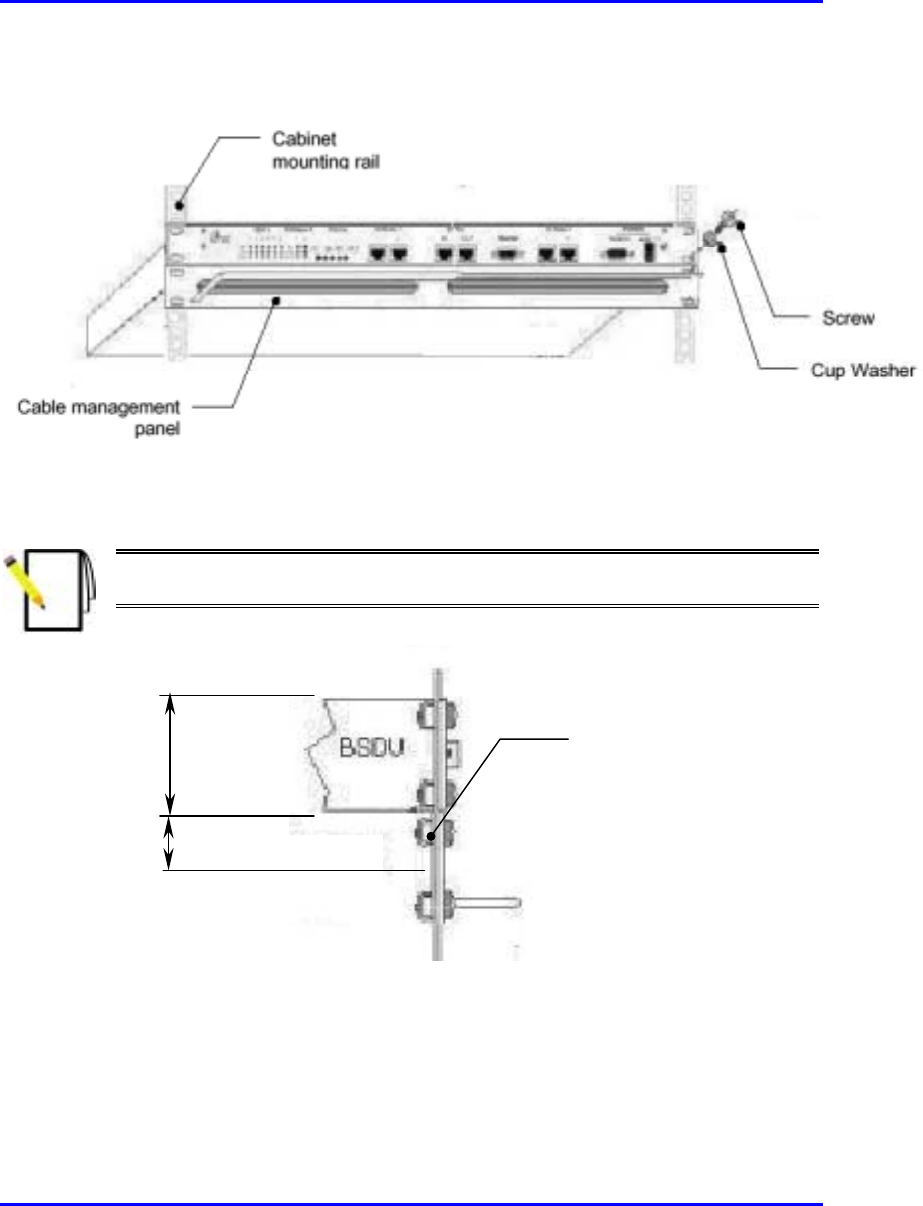
Hardware Installation Manual Installing the BSDU
02030311-03 Airspan Networks Ltd. 5-3
5. Tighten the M5 mounting screws to fasten the chassis to the cabinet.
Figure 5-2: BSDU and cable management panel mounting method
Note: When mounting multiple BSDUs in a cabinet, vertical space—above
and below—is required for threading cables to the rear.
Figure 5-3: BSDU and vertical space for cables
Space for cable
management
1U-chassis

Installing the BSDU Hardware Installation Manual
5-4 Airspan Networks Ltd. 02030311-03
5.3. Cabling the BSDU
Warning:
To avoid electrical shock and fire hazard ensure that all data and powe
r
connections are made prior to connecting the BSDU to the DC power supply.
When installing the BSDU, it is required to wear the wrist strap for ESD.
The BSDU offers services to the WipLL network via both front and rear panels.
interface connections available via the BSDU front panel are as follows:
! Two off RJ45: 100Base-T ports
! Two off RJ45: 10Base-T ports
! One RJ-45: Input for synchronization with previous BSDU in ring
! One RJ-45: Output for synchronization with next BSDU in ring
! One 9-Pin D-type (female) monitor serial port– WipManage interface.
! One 9-Pin D-type (male) Base Station Power System (BSPS) interface port
! DC power input connector -48VDC
! Activity indicator LED’s.
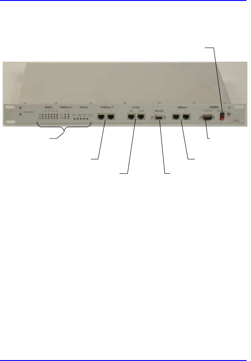
Hardware Installation Manual Installing the BSDU
02030311-03 Airspan Networks Ltd. 5-5
Figure 5-4 shows the front panel of the BSDU.
DC input
Synchronization ports
100BaseT ports
Activity LEDs
Monitor port
10BaseT ports
BSPS port
Airspan
Figure 5-4: BSDU front panel
Interface connections available via the BSDU rear panel are as follows:
! Six 15-Pin D-type connectors which provide DC power, Ethernet connection,
Synchronization and Serial interface to the BSR
! One 15-Pin D-type connector for the Global Positioning System (GPS) antenna
! One 5 mm diameter grounding stud
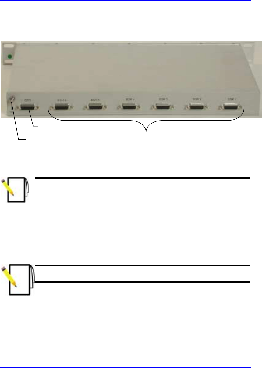
Installing the BSDU Hardware Installation Manual
5-6 Airspan Networks Ltd. 02030311-03
Figure 5-5 shows a rear panel view of the BSDU.
Earth Stud
GPS port
Six BSR ports
Figure 5-5: BSDU rear panel
Note: Airspan supplies unterminated cables for 15-Pin D-type and N-type
connectors. Refer to the cable crimping procedures for these connectors in
Appendix B, “Cable Crimping".
5.3.1. Connecting BSRs to the BSDU
The BSDU rear panel provides six 15-Pin D-type connectors for connecting a
maximum of six BSRs. For a detailed description of connecting BSRs to the BSDU,
see Chapter 4, “Installing the BSR”.
Note: A maximum of six BSDUs can be installed at a base station, allowing
the connection of up to 36 BSRs.
! Connector: 15-Pin D-type (male)
! Connector pinouts: see Chapter 4, “Installing the BSR”.

Hardware Installation Manual Installing the BSDU
02030311-03 Airspan Networks Ltd. 5-7
5.3.1.1. BSR LED indicators
The BSDU front panel includes three LEDs for each of the six BSRs. These LEDs
are described in the following table:
LED LED Status Meaning
On Ethernet activity is detected
Act
Off No Ethernet activity is detected
On Physical link exists between devices
Link
Off No physical link exists between devices
On Current is supplied to the port
Power
Off Port is disabled by software, or port failure
5.3.2. Connecting the GPS antenna
The rear panel of the BSDU provides a 15-Pin D-type connector port—labeled
GPS—for connection to the GPS antenna for clock synchronization. The GPS
allows synchronization between base stations.
For a detailed explanation on connecting the GPS to the BSDU port, see Chapter 6,
“Installing the GPS”.
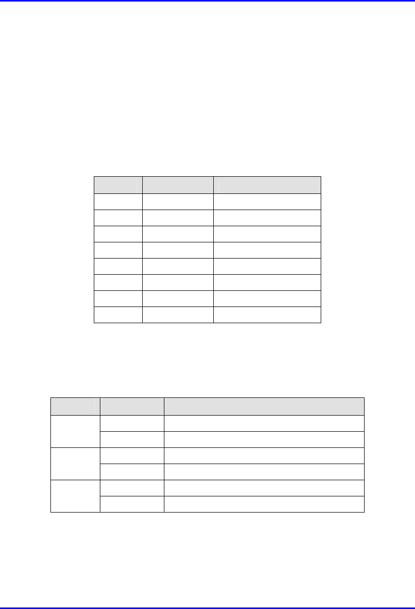
Installing the BSDU Hardware Installation Manual
5-8 Airspan Networks Ltd. 02030311-03
5.3.3. Connecting to 100Base-T Networks
The BSDU’s front panel provides two RJ-45 ports for connection to 100Base-T
(labeled 100Base-T) ports. The 100Base-T ports are for connection to the
management station and Ethernet.
Connector: 8-Pin RJ-45 (male)
Connector pinouts:
Pin Name Description
1 TX+ Transmit Data+
2 TX- Transmit Data-
3 RX+ Receive Data+
4 NC Not connected
5 NC Not connected
6 RX- Receive Data-
7 NC Not connected
8 NC Not connected
5.3.3.1. 100Base-T LED indicators
The BSDU front panel includes three LEDs for each of the two 100Base-T ports.
These LEDs are described in the following table:
LED Status Meaning
On Data is received through the port
Rx
Off No data is received through the port
On Correct physical link between devices
Link
Off No physical link between devices
On Power is supplied to port
100
Off No power at port

Hardware Installation Manual Installing the BSDU
02030311-03 Airspan Networks Ltd. 5-9
5.3.4. Connecting Sync IN/OUT ports
The BSDU’s front panel provides an in/out synchronization 8-Pin RJ-45 ports for
synchronization between BSDUs at the base station. The SYNC OUT of the master
BSDU is connected to the SYNC IN of a slave BSDU, which then connects its
SYNC OUT to the SYNC IN of another slave BSDU, and so on.
Connector: 8-Pin RJ-45 (male)
Cable: straight-through cable
Connector Pinouts:
! Synch IN
Pin Name Description
1 TD+ Transmit data to GPS
2 TD- Transmit data from
GPS
3 RX+ Receive Data (hop
synchronization)
4 NC Not connected
5 NC Not connected
6 RX- Receive Data (hop
synchronization)
7 1PPS+ GPS pulse per second
8 1PPS- GPS pulse per second

Installing the BSDU Hardware Installation Manual
5-10 Airspan Networks Ltd. 02030311-03
! Synch OUT
Pin Name Description
1 TD+ Transmit data to GPS
2 TD- Transmit data from
GPS
3 TX+ Transmit Data (hop
synchronization)
4 RD+ Receive Data (from
GPS)
5 RD- Receive Data (to GPS)
6 TX- Transmit Data (hop
synchronization)
7 1PPS+ GPS pulse per second
8 1PPS- GPS pulse per second
5.3.5. Connecting the Power Management port
The BSDU’s front panel provides a 9-Pin DB-type port for serial RS-232 power
management of the BSPS. WipLL’s WipManage manages BSPS by connecting to
the BSDU through the IP network (i.e., from the BSR), and then manages BSPS
through the serial connection between the BSDU and BSPS. The reason for the
serial connection is that the BSPS does not support SNMP-based management,
which is the bases of WipManage.
Connector: depending on the BSPS model:
! 9-Pin DB-type male (BSDU and BSPS)
! 9-Pin DB-type male (BSDU) to 8-Pin RJ-45 (BSPS) (see Figure 5-6)
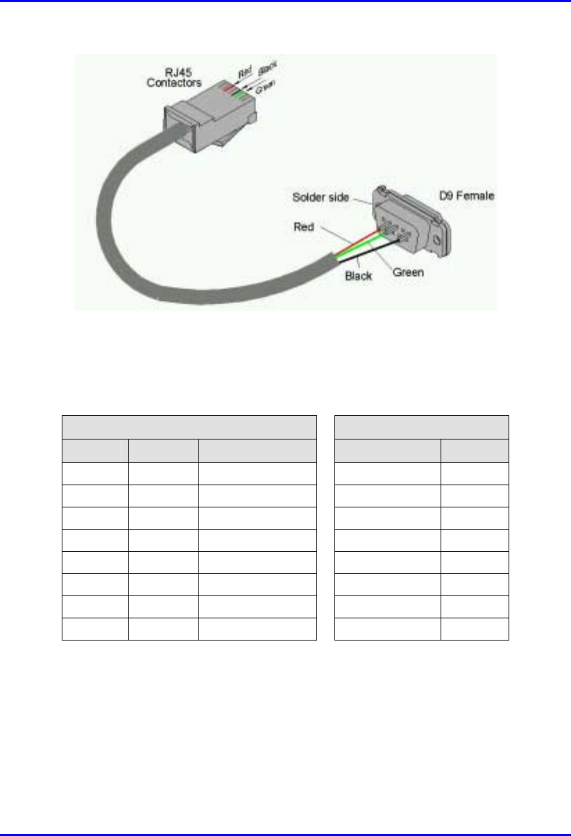
Hardware Installation Manual Installing the BSDU
02030311-03 Airspan Networks Ltd. 5-11
Figure 5-6: BSDU-to-BSPS management connectors – RJ-45 to 9-Pin D-type
Cable length: 60 cm
Connector pinouts:
9-Pin D-type RJ-45
Pin Name Description Pin Name
1 NC Not connected 1 NC
2 RX Receive Data 2 NC
3 TX Transmit Data 3 RX
4 NC Not connected 4 NC
5 GND Ground 5 GND
6 NC Not connected 6 TX
7 NC Not connected 7 NC
8 NC Not connected 8 NC

Installing the BSDU Hardware Installation Manual
5-12 Airspan Networks Ltd. 02030311-03
5.3.6. Connecting Cables for BSDU Serial
Management
The BSDU’s front panel provides a 9-Pin D-type port for serial management
(labeled Monitor) of the BSDU. Serial management allows you to connect the
WipLL’s network management system (WipConfig) to BSDU without assigning
BSDU an IP address.
! Connector: 9-pin D-type male
! Cable: straight-through
! Connector pinouts:
9-Pin D-type Connector
Pin Signal
1 Not connected (NC)
2 RX
3 TX
4 NC
5 NC
6 NC
7 NC
8 NC
9 NC
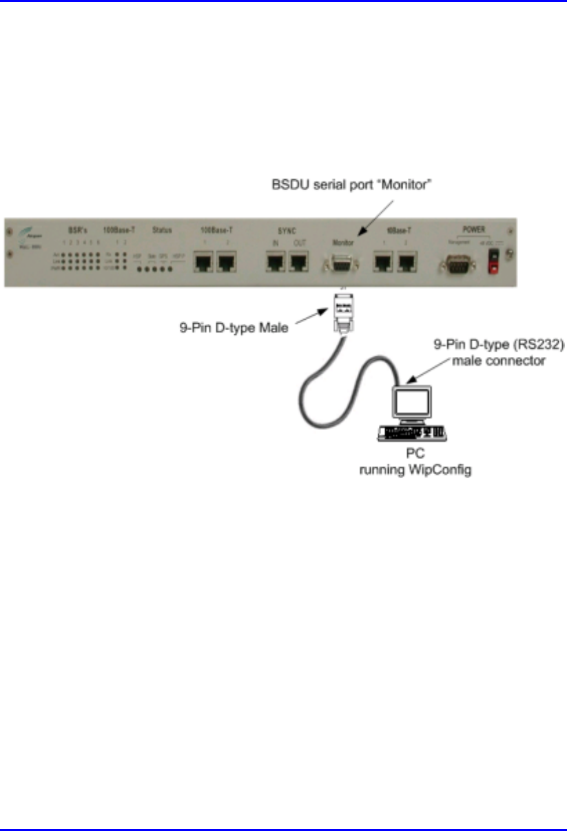
Hardware Installation Manual Installing the BSDU
02030311-03 Airspan Networks Ltd. 5-13
To connect the PC to the BSDU by serial connection (see Figure 5-7):
1. Connect the 9-pin D-type female connector to the PC.
2. Connect the 9-pin D-type male connector, at the other end of the cable, to the
BSDU’s serial port (labeled Monitor).
Figure 5-7: PC-to-BSDU Serial Connections
Installing the BSDU Hardware Installation Manual
5-14 Airspan Networks Ltd. 02030311-03
5.3.7. Connecting Cables for BSDU Network IP
Management
For network (IP) configurations, you can connect the PC to the BSDU’s local port,
or remotely (from anywhere) if you have IP connectivity to the device. For PC-to-
BSDU local network (IP) connections you need to connect the PC to the BSDU’s
10BaseT or 100BaseT port. The BSDU’s front panel provides two 10Base-T ports:
left is labeled 10Base-T 1; right is labeled 10Base-T 2. Port 1 provides PC
management interface to all BSRs connected to the BSDU. Port 2 provides
management interface only to the BSDU. If you connect the BSDU’s two 10BaseT
ports (i.e., loop the ports) to one another by a crossover cable, then you can connect
the PC to one of the BSDU’s 100BaseT ports. If the two BSDU 10BaseT ports are
not connected to one another, then you need to connect the PC to the BSDU’s right-
most 10BaseT port (labeled 10Base-T 2).
Note: For WipLL management, it is recommended to connect Port 1 to Port 2
by a cross-over cable, and then connect the management station (PC) to one
of the 100Base-T ports. In such a setup, you can provide management to all
daisy-chained BSDUs and their associated BSRs through one 100Base-T port.
! Connector: 8-Pin RJ-45 (male)
! Cables:
! Crossover cable for looping the two 10BaseT ports
! Straight-through for connecting the PC to the 100BaseT port

Hardware Installation Manual Installing the BSDU
02030311-03 Airspan Networks Ltd. 5-15
! Connector pinouts:
RJ-45 (10Base-T) RJ-45 (100Base-T)
Pin Signal Pin Function
1 +RX 1 +TX
2 -RX 2 -TX
3 +TX 3 +RX
4
N
C 4
N
C
5
N
C 5
N
C
6 -TX 6 -RX
7
N
C 7
N
C
8
N
C 8
N
C
To connect the PC to the BSDU using a network connection:
1. Connect the RJ-45 connector to the PC’s Ethernet port.
2. Connector the RJ-45 connector, at the other end of cable, to the BSDU’s
10Base-T port labeled 2 (see Figure 5-8);
-Or-
Connect the BSDU’s two 10Base-T ports with the supplied crossover cable, and
then connect the RJ-45 connector to the BSDU’s 1000Base-T port
(see Figure 5-9).
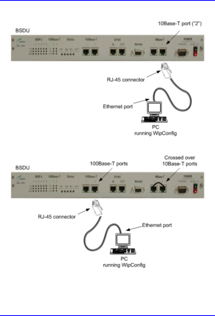
Installing the BSDU Hardware Installation Manual
5-16 Airspan Networks Ltd. 02030311-03
Figure 5-8: PC-to-BSDU Local Network Connection – 10Base-T Port
Figure 5-9: PC-to-BSDU Local Network Connection – 100Base-T Port
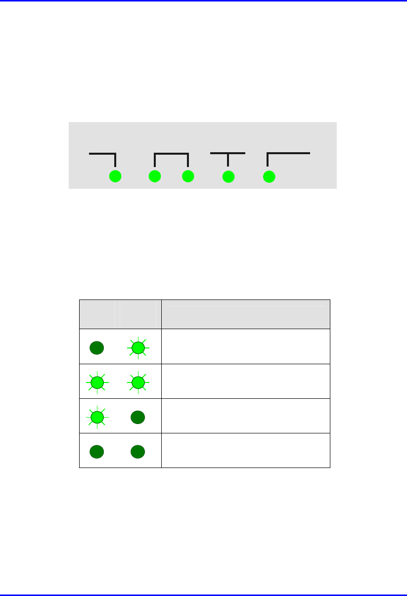
Hardware Installation Manual Installing the BSDU
02030311-03 Airspan Networks Ltd. 5-17
5.4. BSDU LED Status Indicators
The BSDU status LED indicators are located on the BSDU’s front panel, as
displayed in Figure 5-10.
HSP State GPS HSP P
Figure 5-10: BSDU status indicator panel
The LED indicators include the following:
! HSP (Hop Synchronization Process)—this LED indicates that the BSDU
synchronization process is active.
! State—the functions of the State LEDs are described in the following table:
Left
LED Right
LED Function
Synchronization process is starting
This BSDU is the master unit
This BSDU is a slave unit
BSDU sync pulse lost
! GPS (Global Positioning Satellite)—this LED is lit when a GPS is connected to the
BSDU. The LED flashes when receiving a satellite signal.
! HSP P (Hop Synchronization Process Pulse)—this LED indicates the change state
for the HSP pulse.
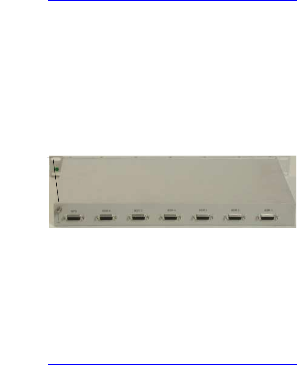
Installing the BSDU Hardware Installation Manual
5-18 Airspan Networks Ltd. 02030311-03
5.5. Connecting Power
The BSDU requires a power supply of –48 VDC. If the base station has no
capabilities of supplying AC-to-DC voltage, the BSDU can be powered by an
optional WipLL BSPS unit (see Chapter 7, “Installing the BSPS”) that supplies –48
VDC power as well as power redundancy.
5.5.1. Grounding (Earthing) the BSDU
Before connecting the power supply to the BSDU, you need to ground the BSDU.
To ground the BSDU:
1. Connect one end of the grounding wire (green/yellow) to the grounding lug
screw located on the rear panel of the BSDU chassis.
Figure 5-11: BSDU rear panel with grounding lug screw
2. Connect the other end of the grounding wire to the cabinet rack or any other
customer grounded point at the base station.
Grounding lug
screw
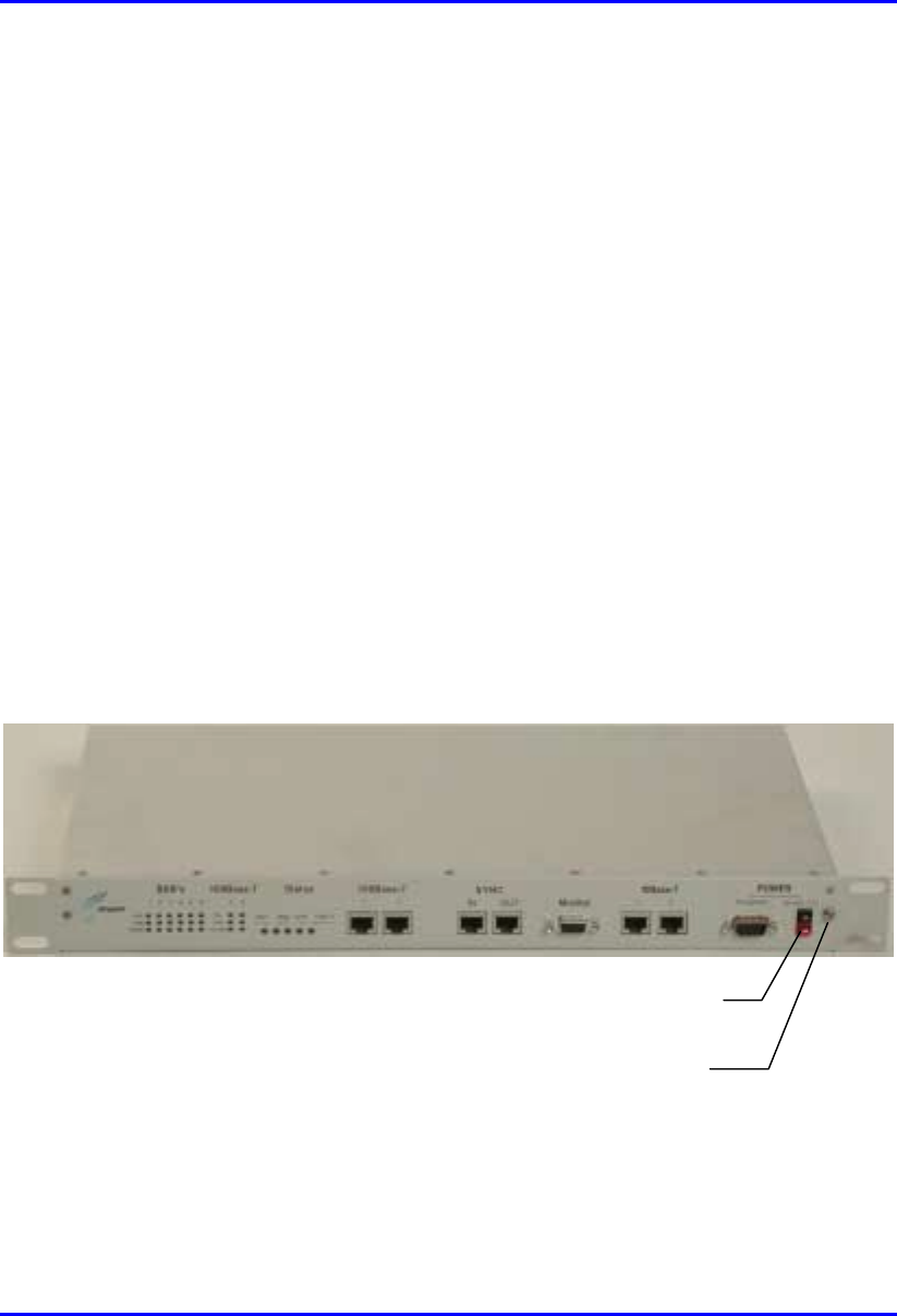
Hardware Installation Manual Installing the BSDU
02030311-03 Airspan Networks Ltd. 5-19
5.5.2. Connecting to Power Supply (BSPS)
The connection between the BSDU and the power supply unit (BSPS) is made via a
two-meter long DC shielded power cable (supplied). The power cable has a power
connector at each end of the cable and a wire for preventing cable disturbances and
radiation. The power cable is connected to the BSDU’s power connector.
The wire color-coding is as follows:
! Red: positive
! Black: negative
To connect the BSDU to the power supply unit:
1. Connect the cable’s power connector side that provides an additional wire for
preventing power radiation, to the BSDU’s power port labeled POWER -48
VDC. Ensure that the black-colored (i.e., negative) side of the connector is
inserted in the upper part of the power receptacle; and the red-colored (i.e.,
positive) side of the connector is inserted in the lower part of the power
receptacle.
Figure 5-12: BSDU front panel with power port and screw attachment for power
radiation immunity
Lug for power cable radiation immunity
Power receptacle

Installing the BSDU Hardware Installation Manual
5-20 Airspan Networks Ltd. 02030311-03
2. Connect the power cable’s yellow/green lug wire, for radiation immunity, to the
BSDU chassis by using the screw attachment located alongside the BSDU’s
power receptacle, as displayed in Figure 5-12.
3. Connect the other end of the power cable to the power source (i.e., to the
customer’s power supply or to the WipLL BSPS).

02030311-03 Airspan Networks Ltd. 6-1
Installing the GPS
Installing the GPSInstalling the GPS
Installing the GPS
The WipLL system provides BSDU connectivity to GPS antennas for synchronizing
multiple base stations and avoiding RF ghosting effects. The GPS antenna ensures
that the entire WipLL network operates with the same clock based on a universal
satellite clock signal.
Figure 6-1: GPS antenna for clock synchronization
6

Installing the GPS Hardware Installation Manual
6-2 Airspan Networks Ltd. 02030311-03
6.1. Mounting the GPS
Depending on individual customer requirements and environmental influences there
are several available options for mounting the GPS:
! Pole Mounting:
The GPS may be mounted to a pole similar to that used to mount the BSR (See
Chapter 4, “Installing the BSR”).
! Mounting Plate:
The GPS may be mounted to a wall or roof top structure using a purpose-made
mounting plate supplied with the unit.
! Direct Mounting:
The unit may be mounted directly to a suitable structure that has been provided
with holes suited to the GPS mounting details.
! Magnetic Mounting:
An optional magnetic mounting device is available to allow GPS mounting to a
suitable surface, e.g., vehicle roof or steel building structure. This device is
attached by means of the threaded holes provided in the base of the GPS.
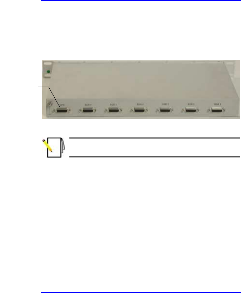
Hardware Installation Manual Installing the GPS
02030311-03 Airspan Networks Ltd. 6-3
6.2. Connecting the GPS to the BSDU
The GPS antenna is connected to the BSDU’s 15-Pin D-type port, labeled GPS (see
Figure 6-2).
Figure 6-2: BSDU rear panel showing GPS port
Note: Airspan supplies un-terminated cables for connecting the GPS to the
BSDU. Refer to Appendix B, “Cable Crimping" for cable crimping procedures
for these connectors.
The following describes the cables and connectors:
! Connector:
! GPS: 12-pin female (Deutsch MMP26C-2212S1)
! BSDU: 15-Pin D-type male
! Cable: Multipair Overall Shielded (22 AWG)
15-Pin D-type
p
ort for GPS
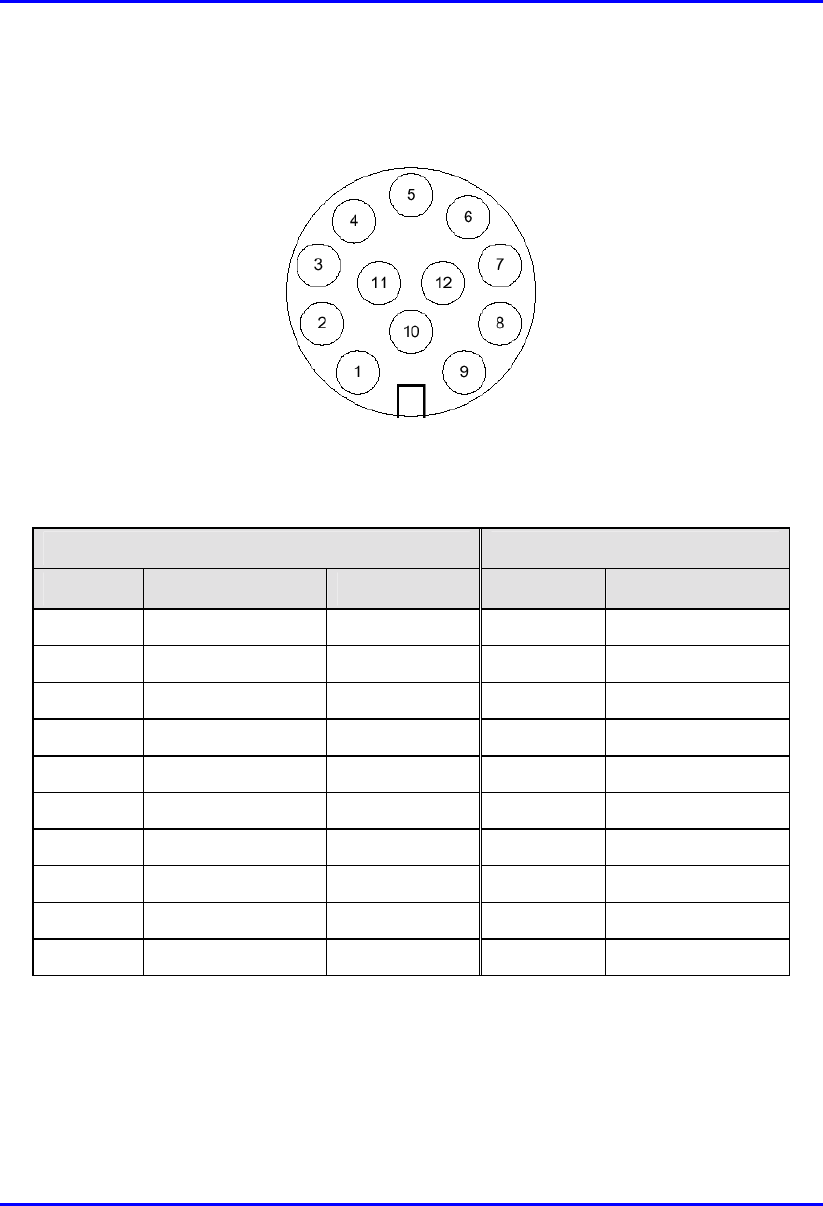
Installing the GPS Hardware Installation Manual
6-4 Airspan Networks Ltd. 02030311-03
! Connector pinouts: The GPS connector receptacle contains 12 male contacts, as
displayed in Figure 6-3.
Figure 6-3: GPS connector pinouts
The connector pinouts for the GPS and BSDU are described in the following table.
12-pin female (GPS) 15-pin D-type male (BSDU)
Pin Pin name Cable color Pin Lead
1 POWER Red 9
2 RX_DATA_1- Blue 5 TD+ (after R5)
3 RX_DATA_1+ Black 6 TD-
4 TX_DATA_1- Yellow 4 RD-
5 TX_DATA_1+ Black 3 RD+ (after R3)
6 RX_DATA_2- Brown x
7 RX_DATA_2+ Black x
9 GND Black 10
11 1PPS+ Green 8 1PPS-
12 1PPS- Black 7 1PPS+ (After R7)
Hardware Installation Manual Installing the GPS
02030311-03 Airspan Networks Ltd. 6-5
To connect the GPS antenna to the BSDU:
1. Connect the 12-pin female connector, at the one end of the cable, to the 12-pin
receptacle connector located at the underside of the GPS.
2. Connect the 15-pin D-type male connector, at the other end of the cable, to the
15-pin D-type port labeled “GPS” at the rear panel of the BSDU.
Figure 6-4 illustrates the BSDU-to-GPS cable connections.
Note:
When installing the cable, secure the cable to the mounting pole or bracket
with a cable tie to hold the weight of the cable (cable strain relief).
A
loop should be left in the dressed cable for maintenance purposes and to
prevent the cable weight being taken directly on the connector itself.
If the cable is supplied by you, ensure that the connector is waterproof.
Warning: To avoid electrical or fire hazard, ensure that the connection to the
GPS is made prior to connecting the BSDU to the power supply.
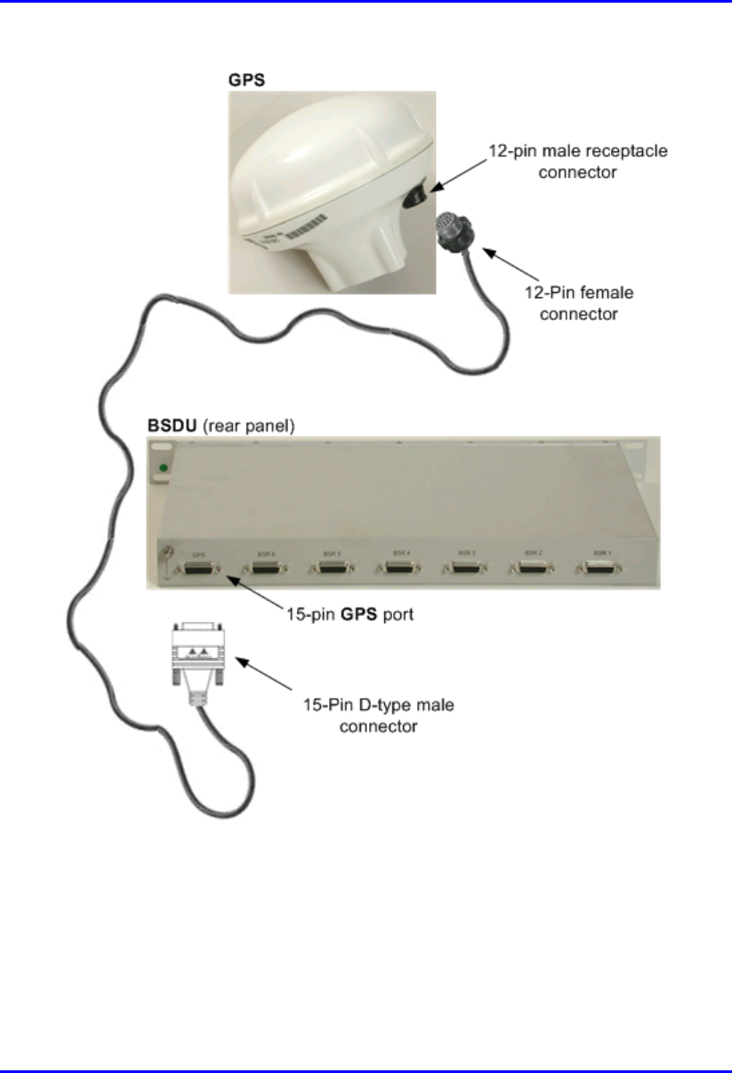
Installing the GPS Hardware Installation Manual
6-6 Airspan Networks Ltd. 02030311-03
Figure 6-4: BSDU-to-GPS cable connections
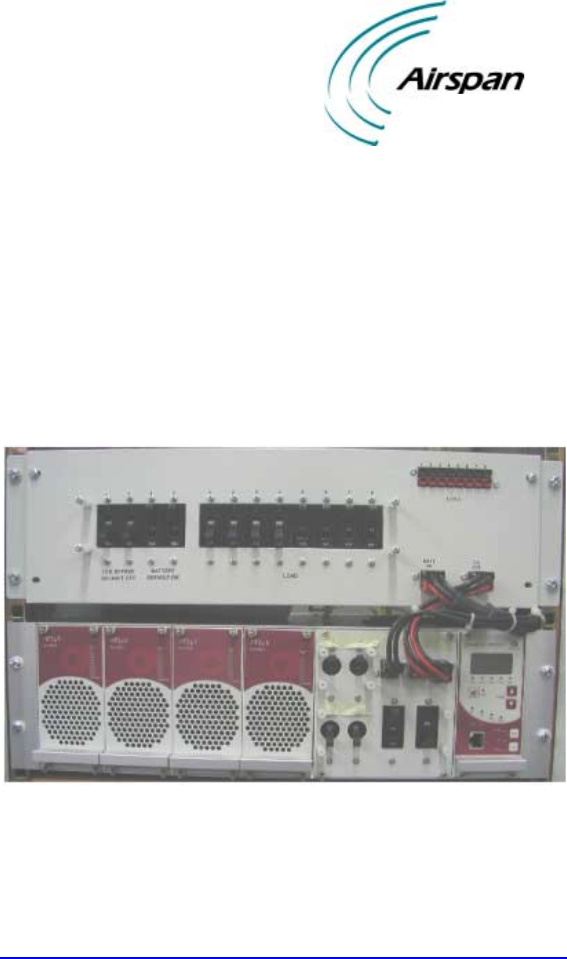
02030311-03 Airspan Networks Ltd. 7-1
Installing the BSPS
Installing the BSPSInstalling the BSPS
Installing the BSPS
The WipLL Base Station Power Supply unit (BSPS) is an optional WipLL unit that
supplies power (and power redundancy) to the BSDU/BSR if no –48 VDC power
supply exists at the base station.
The BSPS front panel is displayed in Figure 7-1.
Figure 7-1: BSPS front panel
7

Installing the BSPS Hardware Installation Manual
7-2 Airspan Networks Ltd. 02030311-03
The BSPS provides the BSDUs/BSRs with the following:
! Power supply of –48 VDC to BSDUs/BSRs
! Power redundancy in case of power failure. The BSPS charges a battery bank
that provides this power redundancy during mains failure. Thus, the BSPS acts
as a DC-UPS with a battery connected to it. The size of the battery determines
the backup and charging time. Since the system is current limited, the maximum
battery size is based on that limit.)
! Remote management and monitoring through WipLL’s WipManage or
WipConfig management application.
The BSPS is delivered pre-installed in an Airspan cabinet. The only installation that
is required includes the following:
! BSPS battery
! BSPS temperature sensor to measure battery temperature
! Connecting the BSPS to the BSDU
7.1. General Site Requirements
Note: Cable sizes and electrical circuit protection devices discussed in the
following section are typical for 230 Volt AC circuits only. Adjustments are
required for applications other than this.
During AC power installation activities at base station premises the following
general requirements should be adhered to:
! The customer must provide a valid safety certificate for the electrical circuit to
which the equipment is to be connected. If this documentation is not available
checks must be carried out in accordance with local electrical installation test
requirements.
! A qualified electrician must carry out the provision of any additional power
outlets.

Hardware Installation Manual Installing the BSPS
02030311-03 Airspan Networks Ltd. 7-3
! Cables used in the customer premises electrical circuit are to be 3-core 6mm2.
Color-coding for live neutral and earth conductors shall be in accordance with
local electrical regulations.
! The base station premises AC distribution panel must be capable of supplying up
to 240 Volts AC.
! The customer is to allocate and clearly identify fuses in AC distribution panel
that will provide protection for equipment in BSPS cabinet. The circuit is to be
protected by a 32 amp protective device in accordance with local standards.
! The customer shall provide a wall mounted AC power socket adjacent to the
BSPS cabinet. Local territory equipment isolation and earth leakage
requirements are to be met when selecting the plug and socket type.
Alternatively a 32-amp isolator switch may be used for connection to the mains
power supply.
! A common earth point (CEP) shall be designated in the customers’ base station
premises to which the system cabinet earth will be connected.
! A minimum separation distance of 200 mm is to be maintained between AC and
DC signaling cables when they run parallel to each other. However these cables
may cross each other at right angles.

Installing the BSPS Hardware Installation Manual
7-4 Airspan Networks Ltd. 02030311-03
7.2. BSPS Components
The BSPS consists of the following basic components:
! DC Rectifier modules: The Rectifier converts the AC current to DC. The BSPS
can house up to four rectifiers. The rectifiers are “hot plugged” and operate in
parallel. This enables the user to define an “N+1”or “N+2”redundant system.
Each rectifier has its own current sharing system, satisfying a complete sharing
among rectifiers.
! System controller
! Electronic Low Voltage Detector (ELVD): The LVD disconnects the battery
from the load, avoiding damage to the battery when over-discharged.
! Battery
! Load and battery circuit breakers for DC protection and distribution
! DC Distribution unit: The DC Distribution unit provides circuit breakers for
distributing the output current to multiple BSDUs.
The unit also contains a bypass switch to bypass the LVD.
Note: For power redundancy, at least two rectifiers must be installed.
The main power rack is housed in a 19” (inches) front mountable chassis.
Figure 7-2 displays the BSPS main components.
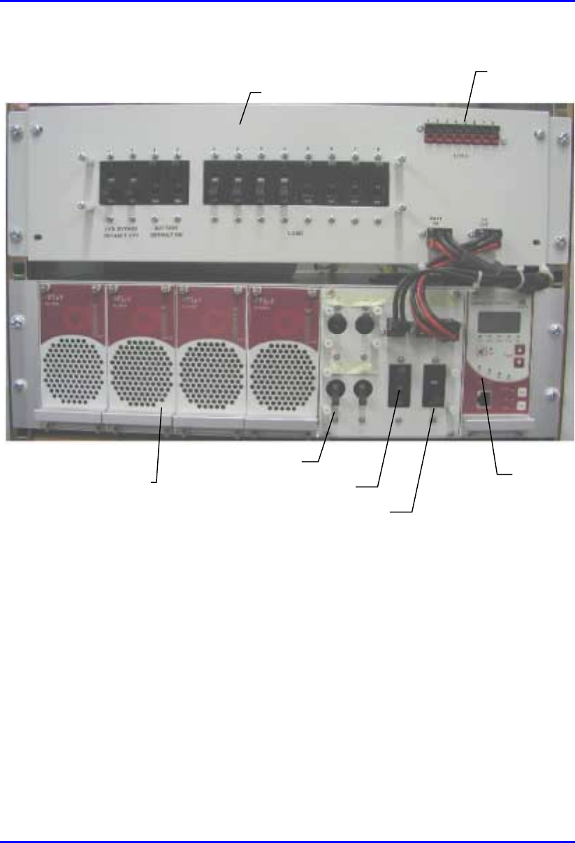
Hardware Installation Manual Installing the BSPS
02030311-03 Airspan Networks Ltd. 7-5
System Controller
Line Breaker
Battery Breaker
Load Breaker
Rectifier module
DC Distribution module
Power ports for connection
to BSDUs
Figure 7-2: BSPS Main Rack front view
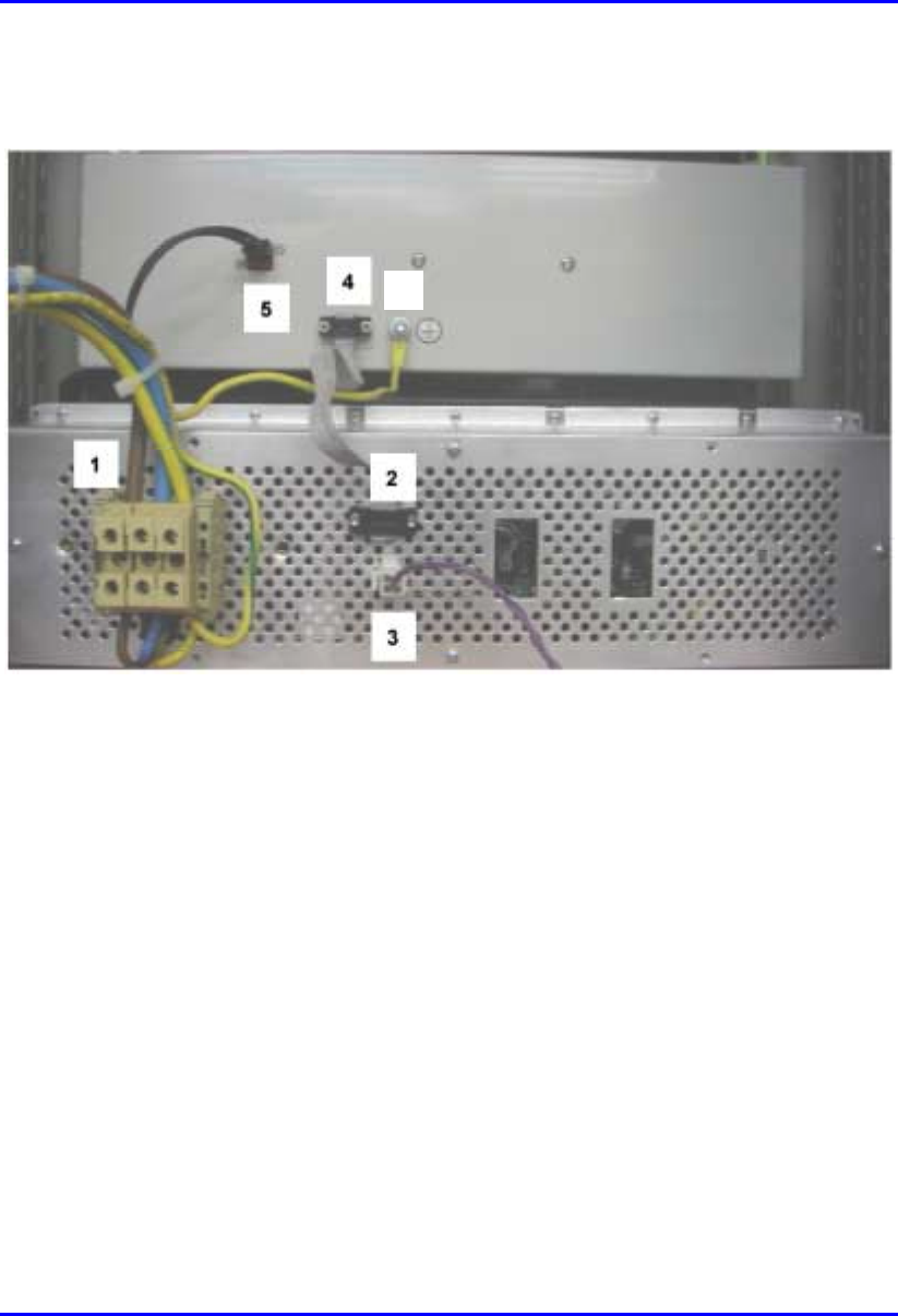
Installing the BSPS Hardware Installation Manual
7-6 Airspan Networks Ltd. 02030311-03
Figure 7-3 displays the rear panel of the main BSPS rack.
6
Figure 7-3: BSPS Main Rack rear view
1. AC connection
2. Comm to DC Distribution
3. Temperature Sensor
4. Comm to power system
5. LVD connection
6. Ground

Installing the BSPS Hardware Installation Manual
7-8 Airspan Networks Ltd. 02030311-03
7.2.1. Installing BSPS Batteries
To provide BSPS system back up power two battery circuits are provided. Batteries
are located on two shelves fitted in the lower sections of the system cabinet.
A battery protection tray is to be fitted beneath the BSPS racks to prevent tools from
falling onto batteries below.
Warning:
Final battery connection, at the DC distribution rack, must only be made once
the battery is fully installed.
The Airspan insulated torque wrench 1PAC10383 AAD must be used when
attaching battery terminations. The wrench is pre-set to ‘break’ at 5.5 Nm
(Newton-meters).
Caution must be observed when fitting and connecting batteries as to prevent
the shorting of connections to the cabinet structure.
Insulated tools and the removal of jewellery are mandatory in all live power
installations.
To install the BSPS battery:
1. Prior to installation use a digital multimeter (DMM) to measure the voltage
output from each monobloc. A reading of 12.3 Volts DC is required from each
monobloc.
2. Install the monoblocs onto the battery trays as shown in Figure 7-4.

Hardware Installation Manual Installing the BSPS
02030311-03 Airspan Networks Ltd. 7-9
Figure 7-4: Cabinet battery area
3. Up to four monoblocs can be housed on each shelf. Connections between the
monoblocs are as illustrated in Figure 7-5.
4. Connect a short battery strap between monoblocs 1 and 2.
5. Using an insulated spanner/wrench tighten the battery terminal nut to the torque
setting recommended by the manufacturer.
6. Using a digital multimeter check across the +ve and –ve terminals of the
connected monoblocs and ensure that a voltage of 24 Volts DC is present.
7. Repeat the above steps for the connections between monoblocs 3 and 4.
8. Connect a long battery strap between monoblocs 2 and 3.
9. Using a digital multimeter check across the +ve and –ve terminals of monoblocs
1 and 4 and ensure that a voltage of 48 Volts DC is present.
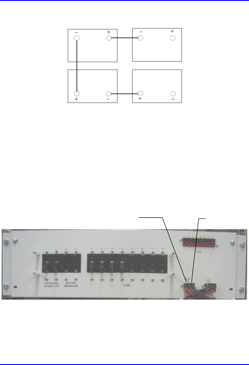
Installing the BSPS Hardware Installation Manual
7-10 Airspan Networks Ltd. 02030311-03
34
2 1
Figure 7-5: Method of interconnection between monoblocs
10. Protect the terminals of the monoblocs using suitable battery grease.
11. Before connecting the BSPS battery cables to the battery ensure that the battery
isolation circuit breakers are in the OFF position.
12. Connect the red lead of the BSPS battery cables to the +ve terminal on
monobloc 4.
13. Connect the black lead of the BSPS battery cable to the –ve terminal on
monobloc 1.
Battery 1
connection Battery 2
connection

Hardware Installation Manual Installing the BSPS
02030311-03 Airspan Networks Ltd. 7-11
14. Check the voltage across the terminals battery input plug DC distribution rack
using a DMM. Ensure that a reading of 48 volts DC is present. If so insert the
plug into the corresponding socket on the front of the DC distribution rack.
15. Repeat the above steps for battery 2 if required.
Note: If any faulty readings were recorded during the process, this would
indicate a damaged monobloc or battery strap. Investigate and replace the
faulty component.
7.3. Installation Summary of the BSPS
The following steps should be carried out when installing BSPS racks:
1. Verify that the circuit breakers of the load, battery and line input are
disconnected and the system is not connected to the line.
2. Connect the main unit to the battery and load via the Battery and Load terminals
on the rear panel.
3. Connect (if needed) the Extension and DC Distribution units. Pay special
attention to the polarities of the wires and locations.
4. Insert a rectifier module into the main unit. All compartments are similar and
connected in parallel.
5. Use 16mm2 (5 AWG) wires for the AC terminals. Minimum requirement is
8mm2 (8 AWG)
6. AC source must be current limited (50A) using an external circuit breaker.
7. Plug the AC input cord into the AC source.
8. Turn on the Line circuit breaker, and verify that the system controller is
activated.
9. Insert the other rectifiers, and verify all green LED's on the panels are lit.
10. All parameters such as the output voltage are pre-defined in the factory.
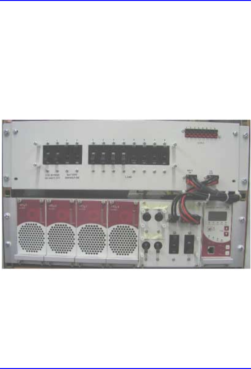
Installing the BSPS Hardware Installation Manual
7-12 Airspan Networks Ltd. 02030311-03
11. Connect the temperature sensors to the appropriate connector at the rear panel of
the main unit. Place the sensors in the battery compartment.
12. Switch on the LOAD and BATTERY circuit breakers. Verify that the BYPASS
breakers are off.
The system is now ready for use.
13. Verify that the FAULT red LED is not lit and the buzzer not active.
14. Connect a PC to the RJ-45 port at the front panel of the main unit to control the
system (optional).
Figure 7-6: BSPS Main Rack front view
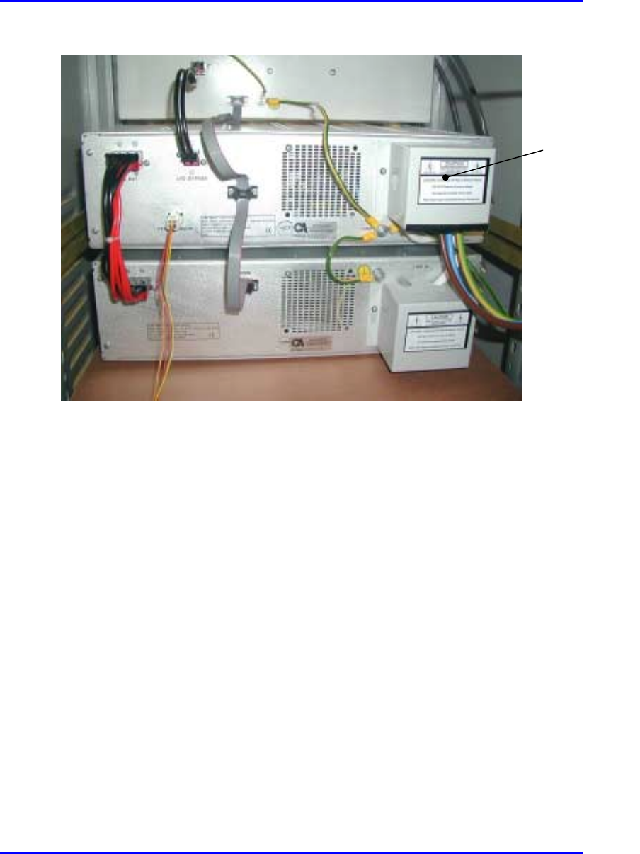
Hardware Installation Manual Installing the BSPS
02030311-03 Airspan Networks Ltd. 7-13
Figure 7-7: Rear BSPS cable connections
7.3.1. Connecting Power to BSDUs
The BSPS’s DC Distribution unit provides circuit breakers for distributing power
output to BSDUs housed in the WipLL cabinet.
The DC Distribution unit contains a switch that provides an LVD circuit bypass
option. When this switch is activated the battery is no longer protected against deep
discharge and the system controller alarm is then activated.
The distribution rack is provided with front panel and rear panel terminations for
connecting to the BSPS main power rack.
To connect the BSPS DC power supply to the BSDU:
1. Attach the shielded power cable connector (supplied) end that contains the wire
for preventing power radiation, to the BSDU’s power port—labeled POWER -
48 VDC. Ensure that the black-colored (i.e., negative) half of the connector is
positioned at the top and the red-colored (i.e., positive) half at the bottom.
Protective
covers
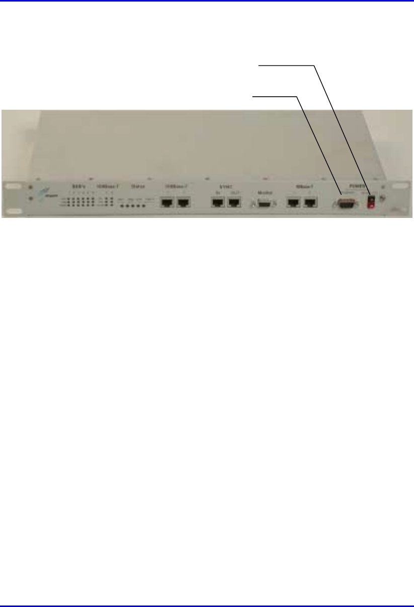
Installing the BSPS Hardware Installation Manual
7-14 Airspan Networks Ltd. 02030311-03
Figure 7-8: BSDU front panel with power port and screw attachment for power
radiation immunity
2. Connect the power cable’s yellow/green lug wire, for radiation immunity, to the
BSDU chassis by using the screw attachment located alongside the power port,
as displayed in Figure 7-8.
3. Connect the other end of the power cable to the DC output port of the BSPS’s
DC Distribution unit (labeled LOAD).
The rack front panel is shown in Figure 7-9.
Screw for power cable
radiation immunit
y
Power port
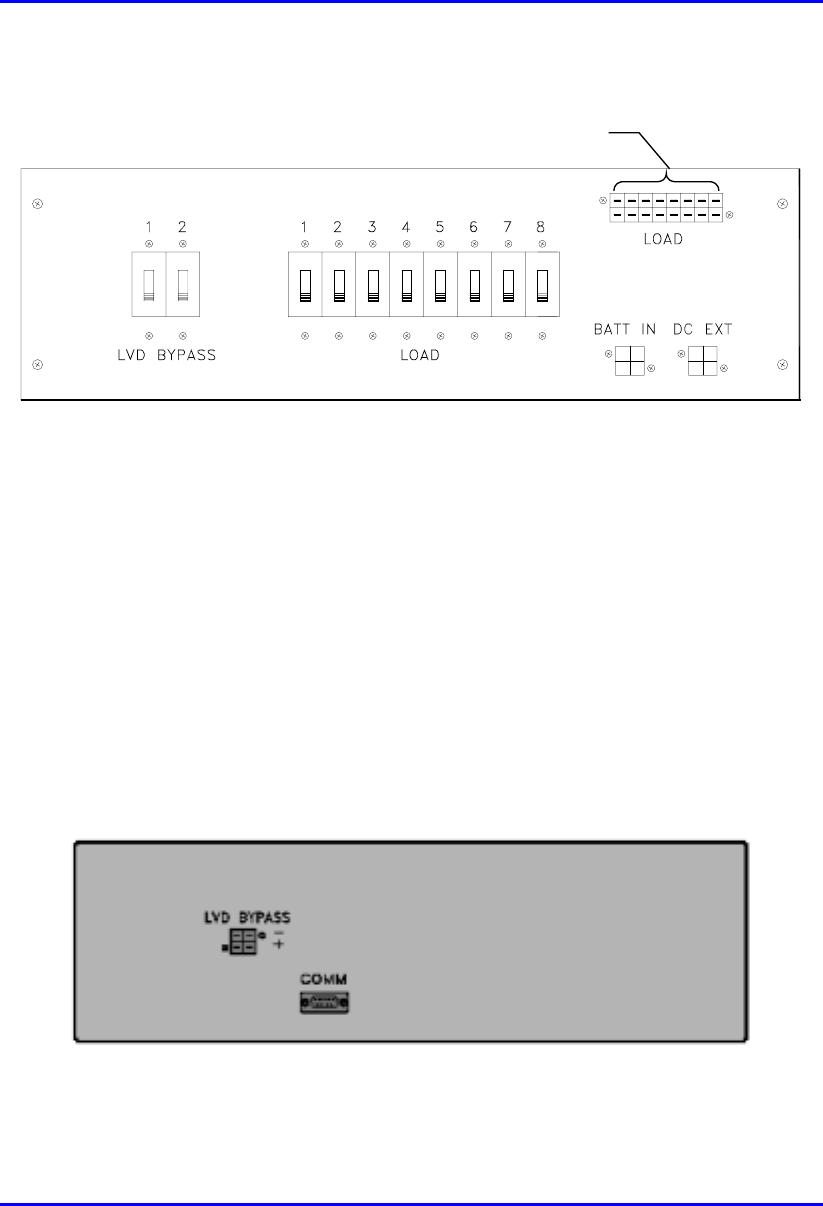
Hardware Installation Manual Installing the BSPS
02030311-03 Airspan Networks Ltd. 7-15
DC power connections
to BSDUs
Figure 7-9: DC Distribution Rack front view
! LOAD DC—DC connection to BSDUs
! DC EXT—extension rack DC power input connection
! BATT IN—battery input connection
! LVD BYPASS—bypass circuit breakers
! LOAD—load circuit breakers
The rack rear panel is shown in Figure 7-10.
Figure 7-10: DC Distribution Rack rear view

Installing the BSPS Hardware Installation Manual
7-16 Airspan Networks Ltd. 02030311-03
! LVD BYPASS—LVD bypass input connection from main rack
! COMM—Main/Extension Rack Communication port
7.3.2. Installing the Rectifier
The Rectifier module is the heart of the Full-Redundancy 48 VDC power system. It
converts the input AC to DC current. The Rectifier is a plugged-in module designed
specifically for modular systems. The BSPS can house up to three basic rectifiers.
To install a rectifier in the BSPS system:
1. Remove the blank panel from where you want to install an additional rectifier in
the rectifier shelf.
2. Insert the rectifier into its place with the upper and lower slides.
3. Secure the rectifier in place with 4 screws in the front panel.
4. Verify that the ON LED is lit.
5. If there is a load on the BSPS system, verify, via the Load Bar, that there is
current sharing in the BSPS system by the rectifier.
7.3.3. Calibrating the Rectifier
The output current indication is indicated by an LED bar graph shown on the unit
front panel. This bar graph is used to verify current sharing operation between
modules fitted in the rack, and to indicate the percentage of the full load.
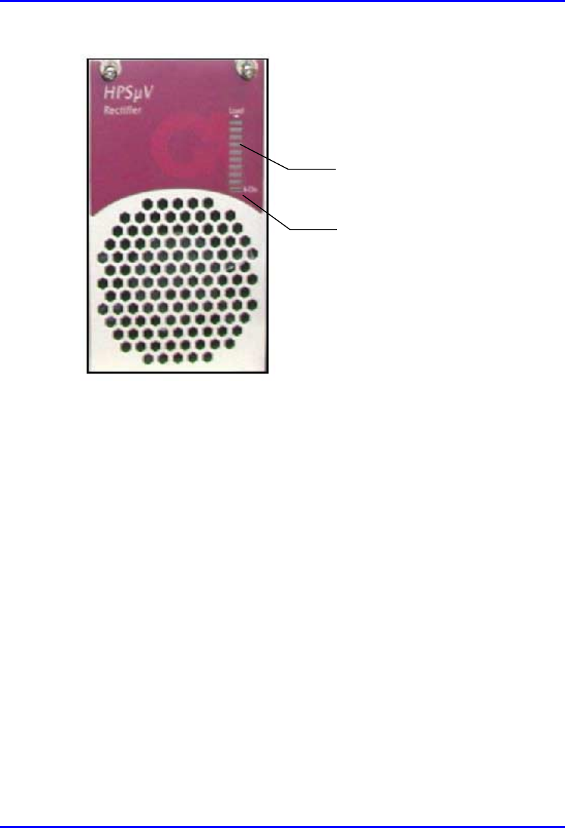
Hardware Installation Manual Installing the BSPS
02030311-03 Airspan Networks Ltd. 7-17
On LED indicator
Bar graph
Figure 7-11: Rectifier module front view

Installing the BSPS Hardware Installation Manual
7-18 Airspan Networks Ltd. 02030311-03
The calibration of the Rectifier module is simple and involves a single trimmer-
potentiometer that adjusts the output voltage.
To calibrate the rectifier:
1. Remove the rectifier from the unit.
2. Connect the Share (+) bus to the negative pole (-) of the rectifier.
3. Using a DMM set the output voltage to 53.50 VDC.
4. Check the single rectifier using a female connector (such as the one used in the
units of the system).
Or
5. Perform provisions for the calibration on a dedicated unit.
6. Access the trimmer via the small opening at the back of the cover.

Hardware Installation Manual Installing the BSPS
02030311-03 Airspan Networks Ltd. 7-19
7.3.4. Operating the System Controller
Figure 7-12 shows the features provided on the front panel of the system controller
module.
Figure 7-12: System controller front panel
8-pin RJ-45 port

Installing the BSPS Hardware Installation Manual
7-20 Airspan Networks Ltd. 02030311-03
The function of the LED’s provided on the System controller module can be defined
as follows:
LED Color Meaning
AC Green Input AC voltage is normal
DC Green Output DC voltage is normal
LVD Red State of the Low Voltage Disconnect circuit: red indicates that
the battery is disconnected
BATT Green Battery test has passed
Red continuous General fault alarm
FAULT
Red blinking Faulty rectifier detected
The following lists the buttons and their functions on the System Controller module.
Button Function
BATT TEST This is a manual battery test button. A pencil tip may be used to activate.
ALARM OFF This button silences the module internal buzzer. A pencil tip may be used to
activate.
RESET This button resets the module. A pencil tip may be used to activate.
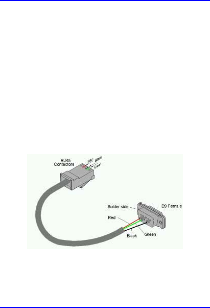
Hardware Installation Manual Installing the BSPS
02030311-03 Airspan Networks Ltd. 7-21
7.4. Connecting the BSPS Management Cables
Connecting the BSPS’s System Controller module to the WipLL BSDU provides the
user with the ability to control the power system operating parameters, retrieving
system data, and status information.
The BSPS System Controller connects to the BSDU(s) via an RJ-45 port located on
the front panel of the controller module. This is connected to BSDU’s 9-Pin D-type
port, labeled POWER Management.
! Connectors:
! BSPS: 8-pin RJ-45 (or for previous BSPS models, a 9-Pin D-type)
! BSDU: 9-pin D-type female
! Connector pinouts:
! BSPS’s 8-Pin RJ-45:
Figure 7-13: BSDU-to-BSPS management connectors via RJ-45 (BSPS) to 9-Pin D-
type (BSDU)
! BSDU’s 9-pin D-type:
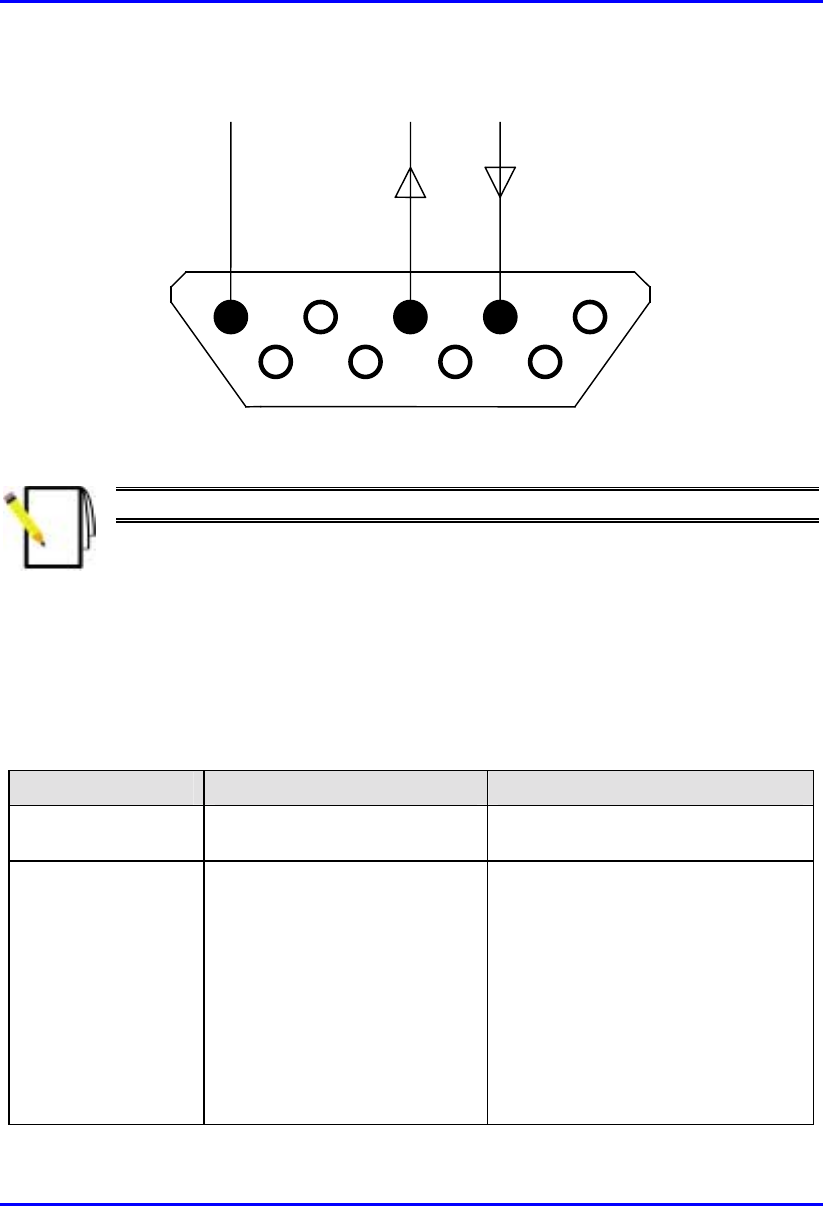
Installing the BSPS Hardware Installation Manual
7-22 Airspan Networks Ltd. 02030311-03
1 5
6 9
Rx
Tx
COM
Figure 7-14: BSDU’s 9-pin D-type Connector Pinouts
Note: See Chapter 5, “Installing the BSDU” for detailed connector pinouts.
7.4.1. BSPS Troubleshooting
The table below indicates methods of solving problems that may arise during the
BSPS installation process.
BSPS troubleshooting tips
Symptom Possible Cause Remedy
FAULT LED is
blinking One or more rectifier modules
are faulty Replace the faulty rectifier/s
FAULT LED is on
• Any breaker is left open
• Abnormal input or output
voltages
• Over temperature
• LVD is open
• Battery test failed
• Check all breakers
• Check line voltage and load,
rectifiers may be over-loaded
• Check the temperature sensor
• Check the line, general check
• Check the battery breaker, cables
and replace battery if none of this
helps

Hardware Installation Manual Installing the BSPS
02030311-03 Airspan Networks Ltd. 7-23
Symptom Possible Cause Remedy
No backup time
when AC is absent Battery is not connected
Battery is discharged or power
is low.
Check battery charge, connections
and circuit breaker
Load is not operating Load is not connected • Check load cables.
• Check load circuit breaker.
No current sharing
among rectifiers
(more then 2
segments difference
between any two
modules).
• Load is too high.
• Extension rack is not
properly connected to the
main rack.
• Rectifier(s) are not properly
adjusted.
• Decrease the load or add rectifiers
to the system.
• Check connections.
• Re-adjust the voltage of the
problematic rectifier(s).
Battery backup time
is too low
• Battery is too small for the
application.
• Charging voltage is too low
• Weak battery
• Increase battery capacity
• Raise the system output voltage
using the “VOLT ADJ.”
• Replace the battery and check
ambient temperature according to
manufacturer’s instructions
7.5. BSPS Cabinet Cabling
This section defines the procedures to be adhered to when installing data cables in
the BSPS cabinet.
Note: A minimum separation of 200 mm should exist between power and data
cables.
! Cable access apertures are located in the top surface of the cabinet. Separate
apertures are provided for power and data cables. All cabling entering and
exiting the BSPS cabinet shall be protected using flexible conduit and gland
systems suited to the cabinet. Power and data cables should exit from the BSPS
cabinet via separate apertures.
! Data cables are to be secured to cable guides provided on the left-hand side of
the cabinet when viewed from the rear. Cables are to be brought together to a

Installing the BSPS Hardware Installation Manual
7-24 Airspan Networks Ltd. 02030311-03
point on the cable guide from where they can be fanned out and fed to the Base
station Distribution Units (BSDU’s).
! Data cables terminating at the front of the BSDU’s should be fed through the
brush gland fitted adjacent to the units and secured to the cable management bar
using tie-wraps.
! When cabling the BSPS cabinet consideration should be given to future growth
and expansion. Allowances in cable forms should be made for the removal of
equipment for maintenance, i.e., BSDU’s, Power racks etc.
! Where cables are installed but not connected to equipment they should be tied
off in such a way as to prevent damage, allow for future growth and
maintenance. Pre-terminated cables should be treated with care and should not
be laid out in vulnerable areas where they may be susceptible to damage.
! Cable crossovers should be kept to a minimum to prevent system interference
and allow easy equipment removal.
! Ensure that the cables are dressed in such a fashion that they are not exposed to
hot exhaust air, sharp edges, doors etc.
! Observe recommended minimum bend radii when installing copper cables.
Wherever a cable changes direction, ensure that it does so in a smooth curve
with a radius of at least 50mm in order to prevent damage.
! Cables shall be secured directly to cabinet cable trays with plastic cable ties.
Secure the data and power cables at regular intervals within the cabinet to the
cable management trays/trunking provided using cable ties. These ties should be
tensioned and cut using the supplied tool 1PAC10370ACK.
! Care is to be taken to ensure that cables providing connection to peripheral
equipment (e.g. PC’s) do not pose a trip hazard.
! WipLL system interface cables providing connection to a network shall be
terminated and presented to a digital distribution frame (DDF) as agreed with the
customer. Dressing of cables at the DDF shall be done to ensure a potential trip
hazard is not created.

Hardware Installation Manual Installing the BSPS
02030311-03 Airspan Networks Ltd. 7-25
! All data cables should be labeled with both the source and destination at each
end. Un-used cable ends must also be identified with labels to assist with future
upgrades.
7.5.1. BSPS Cabinet Grounding
Warning: The WipLL BSPS cabinet must be connected to the customers
building common earth point (CEP) earth before connecting AC power supplies
and installing any equipment.
! When the BSPS cabinet has been located an earth cable shall be run from the
building common earth point (CEP) to the primary earth stud of the cabinet.
! Earth cable specification is to be 6mm2. Cable color-coding is to comply with
local regulations.
! Crimp M6 x 6mm2 lug to the end of the cable to be attached to the CEP with
crimp tool ‘BMR 16U3’ (Airspan Code 1PAC10336AED).
! The required length of cable is to be measured back to the cabinet earthing stud
and the excess removed.
! Crimp M6 x 6mm2 lug to the cable end to be attached to the cabinet earth stud
using crimp tool ‘BMR 16U3’ (Airspan Code 1PAC10336AED).
! Attach the earth cable to the CEP using fastenings provided.
! Attach the earth cable to the cabinet primary earth stud using the fastenings
provided.
7.5.2. BSPS Equipment Supplementary Grounding
! Equipment housed in the BSPS cabinet must be supplementary grounded by
connecting a ground lead between each unit ground stud and the cabinet primary
ground stud.
! Cable specification is to be 2.5 mm2. Cable color-coding is to comply with local
regulations.

Installing the BSPS Hardware Installation Manual
7-26 Airspan Networks Ltd. 02030311-03
7.5.3. BSPS Cabinet Power Requirements
The following section describes the BSPS cabinet mains power requirements.
Warning: The following information assumes a fully populated BSPS cabinet
with main and extension power racks fitted.
Cable sizes and electrical circuit protection devices discussed in the following
section are typical for 230 Volt AC circuits only. Adjustments are required fo
r
other applications.
! Within the BSPS cabinet protected AC mains feeds are required for the main
power rack and two power outlets.
! Both power outlets are to be installed within the cabinet on an independent radial
circuit. Sockets are to be used for the connection of ancillary test/commissioning
equipment only. The type of socket used is dependant on local electrical
requirements.
! Power within the BSPS cabinet is to be distributed from a modular AC consumer
unit fitted with a 100 amp DP isolator. The unit is to be a metal-clad type with
sufficient outputs for services in the cabinet.
! The following tables displays the protective device rating and cable specification
required for each element of the cabinet AC circuit.
Service Fuse Rating Cable Spec
Cabinet power input 32 amp 6 mm2
Main rack input 16 amp 2.5 mm2
Extension rack link N/A 2.5 mm2
Power socket No.1 6 amp 1.5 mm2
Power socket No.2 6 amp 1.5 mm2
! Provision is made on the rear of the BSPS main power rack for the AC power
connection. A terminal block is provided for the link to the extension power rack
when fitted.
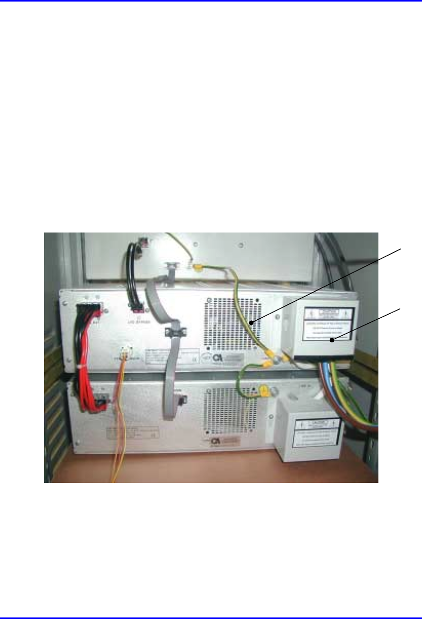
Hardware Installation Manual Installing the BSPS
02030311-03 Airspan Networks Ltd. 7-27
! A terminal block is provided on the rear of the power extension rack for the link
from the main power rack.
! When connecting racks to the AC mains supply loosen the grub screws on the
terminal blocks. Insert the bare copper conductor ensuring correct polarity.
Firmly tighten the screw and gently pull on each cable to ensure the grub screw
has made full contact. Ensure that bare wires are not exposed.
! The plug fitted to the BSPS cabinet power input cable is to be compatible with
the socket provided in the customers’ premises. It must comply with local
regulations for connection of products with earth leakage exceeding 3.5 mA.
! Once AC power connections to the power racks are completed fit protective
covers over the terminal blocks as shown in Figure 7-15.
Figure 7-15: Fitting protective covers over terminal block
! Power cables are to be routed in the cable guide down right-hand side of the
BSPS cabinet (when viewed from the rear).
! Secure cables in position using strategically located cable ties.
Protective
cover
Supplementary
earth
connection

Installing the BSPS Hardware Installation Manual
7-28 Airspan Networks Ltd. 02030311-03
! Power cables external to the BSPS cabinet must be housed in trunking. The
trunking is to be secured to the wall of the equipment room. Type, securing
method and route of trunking is to be in accordance with customers’
requirements.
! A minimum separation distance of 200 mm is to be maintained between AC and
DC/signaling cables when they run parallel to each other. However these cables
may cross each other at right angles.
! Any dust/debris created during the installation of electrical equipment or cables
shall be cleared and correctly disposed of as the installation progresses.

Part II
Part IIPart II
Part II
Installing WipLL Customer
Installing WipLL Customer Installing WipLL Customer
Installing WipLL Customer
Premises Equipment
Premises EquipmentPremises Equipment
Premises Equipment
Part II describes the procedures for installing the WipLL equipment located at the
subscriber’s premises.
Part II includes the following chapters:
! Chapter 8, “Installing the Subscriber Premises Radio (SPR) and Subscriber Data
Adapter (SDA)”
! Chapter 9, “Installing the Indoor Data Radio (IDR)”
This page is intentionally left blank.

02030311-03 Airspan Networks Ltd. 8-1
Installing the SPR
Installing the SPRInstalling the SPR
Installing the SPR
This chapter describes the installation of the WipLL Subscriber Premises Radio
(SPR) at the subscriber's premises.
This chapter includes the following chapters:
! Overview
! Physical Dimensions and Basic Design
! Cable Guidelines
! Mounting the SPR
! Minimum Distance between SPRs
! Wall Mounting
! Pole Mounting
! Connecting to an External Third-Party Antenna (Optional)
! Connecting to a PC for Initial Serial Configuration
! Connecting to the SDA
! Connecting to a Power Supply
8

Installing the SPR Hardware Installation Manual
8-2 Airspan Networks Ltd. 02030311-03
8.1. Overview
The SPR receives and transmits data from and to the base station. The SPR connects
to the subscriber’s network through the SDA. The SDA is an Ethernet hub/LAN
switch that provides the SPR with DC power, lightening protection, and Ethernet
connectivity to the subscriber’s PCs/network. The SPR connects to the SDA by a
CAT-5e cable.
The SDA provides 10/100BaseT connectivity (depending on the SDA model) to the
subscriber’s PCs or network (up to four PCs depending on SDA model).
The SPR is typically mounted on the subscriber's roof or external wall The SDA is
located inside the subscriber's premises.
The SPR is available in three models:
! SPR with Standard Gain: includes a built-in antenna 15/16-dBi antenna gain,
covering an area of 23 degrees
! SPR with High-Gain Antenna: includes a built-in antenna with an 18-dBi
antenna gain, covering 15 degrees.
! SPR with external antenna: includes an N-type connector port for attaching a
third-party external antenna.
Figure 8-1 displays a typical setup of the SPR and SDA at the subscriber's premises.
Note: The SDA can also be installed at a base station that has only one BSR.
This SDA replaces the need for the BSDU, and provides power and
connectivity to the single BSR.
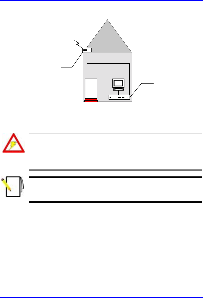
Hardware Installation Manual Installing the SPR
02030311-03 Airspan Networks Ltd. 8-3
RF link
CAT-5e
PC
Figure 8-1: Typical SPR and SDA location and connections at subscriber's premises
Warning: As the system emits microwave radiation, a minimum distance o
f
200 mm must be maintained from the front of the SPR.
To avoid electrical or fire hazard, connect the SPR to the power supply only
after mounting the SPR and connecting data cables between the SPA and
SDA units.
Note: Usually, the SPR is initialized (i.e., configured with an IP address) at
Airspan's factory. However, if the SPR has not been configured, see Section
8.6, “Connecting to a PC for Initial Serial Configuration”, before mounting the
SPR.
Subscriber Data
Adapter (SDA)
located inside
Subscriber Premises
Radio (SPR) located
on the roof
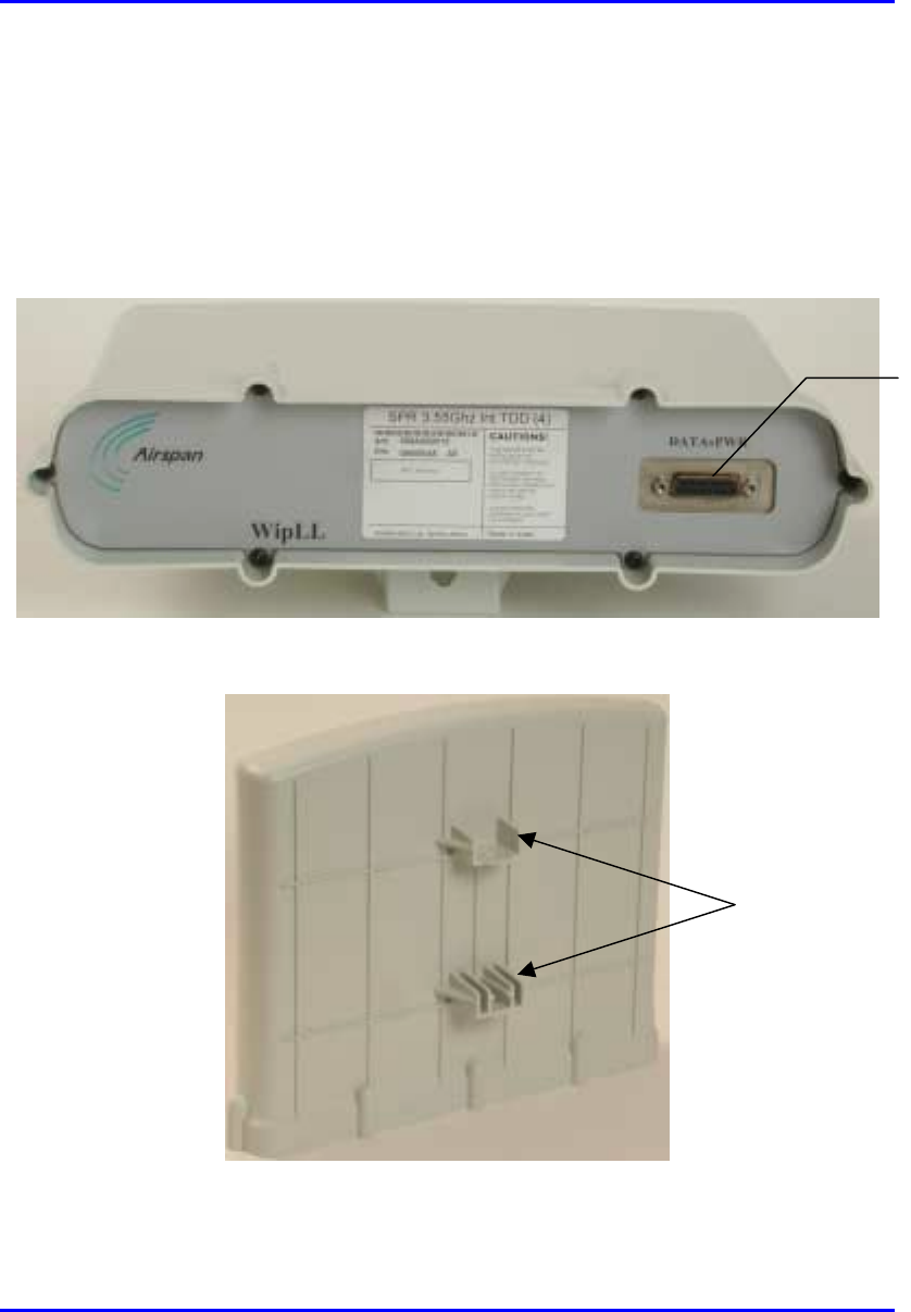
Installing the SPR Hardware Installation Manual
8-4 Airspan Networks Ltd. 02030311-03
8.2. Physical Dimensions and Basic Design
The SPR is encased in a chassis and provides access to the SPR’s communication
port at the front panel. The SPR’s bottom panel provides holes for mounting the
SPR to, for example, a pole or wall (see Figure 8-3).
Figure 8-2: SPR (internal antenna model)
Figure 8-3: SPR bottom panel providing holes for mounting
Mounting holes
15-pin D-type
p
ort

Hardware Installation Manual Installing the SPR
02030311-03 Airspan Networks Ltd. 8-5
The SPR’s physical dimensions are described in Table 8-1
Table 8-1: SPR Physical Dimensions
SPR model Parameter
Standard Gain Antenna High Gain Antenna
Height 311 mm (12.24 inches) 400 mm (15.74 inches)
Width 224 mm (8.82 inches) 317 mm (12.48 inches)
Depth 65.5 mm (2.58 inches) 65.5 mm (2.58 inches)
Weight 2.5 kg 4.7 kg
Note: The SPR’s physical dimensions exclude the mounting kit.
8.3. Cable Guidelines
The following lists cable installation guidelines at the subscriber's premises:
! To prevent tripping, wiring channel is to be provided at the subscriber's premises
to house data cables. Wiring channel type, location, and methods of securing are
to be discussed with the subscriber.
! Cables not housed in wiring channel must be dressed in a manner to avoid a trip
hazard. Avoid trailing wires across passageways.
! External data cables are to be protected in metal conduit that is to be secured to
the building structure in accordance with manufacturers recommendations.
! Outside wiring channels must not be located as to cause a trip hazard (e.g. roof
walkways)
! Observe recommended minimum bend radii when installing copper cables.
Wherever a cable changes direction, ensure that it does so in a smooth curve
with a radius of at least 50 mm in order to prevent damage.
Installing the SPR Hardware Installation Manual
8-6 Airspan Networks Ltd. 02030311-03
! A maintenance loop is to be left in the cable just before the cable reaches the
SPR to prevent strain on the connector.
! Data cables threaded into holes drilled in walls are to be covered by a waterproof
sheath to prevent water penetration.
! Silicone sealant should be used to plug any holes on both internal and external
wall surfaces once cables are in place.
! All data cables should be labeled with both the source and destination at each
end.. Un-used cable ends must also be identified with labels to assist with future
upgrades.
Warning: Cables with exposed ends (i.e., not yet crimped) should be covered
with protective polythene bags during external cable installation processes.
Note: A minimum separation of 200 mm should exist between power and data
cables.
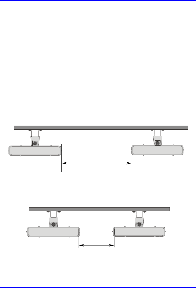
Hardware Installation Manual Installing the SPR
02030311-03 Airspan Networks Ltd. 8-7
8.4. Mounting the SPR
The SPR can be mounted on a wall or pole (see Figure 8-9). The SPR is mounted
using the mounting holes located on the SPR’s bottom panel, and the mounting
bracket (provided). The mounting brackets for wall- and pole-mounting are different
from one another.
The following is a list of physical parameters that should be considered before
mounting SPRs:
8.4.1. Minimum Distance between SPRs
A minimum of 3-meter separation is required between mounted SPRs and existing
customer radio equipment when not transmitting on the same sector (see Figure 8-4).
3.0 metres
Figure 8-4: SPR separation when not transmitting on the same sector
A 1-meter separation is required between SPRs when on the same sector and
transmitting to the same BSR without requiring shielding (see Figure 8-5).
1.0 metre
Figure 8-5: SPR separation when transmitting on the same sector to the same BSR

Installing the SPR Hardware Installation Manual
8-8 Airspan Networks Ltd. 02030311-03
8.4.2. Wall-Mounting
SPR wall mounting is performed in two chronological stages:
! Attaching the mounting bracket to the SPR’s mounting holes.
! Attaching the mounting bracket (attached to the SPR) to the wall.
To mount the SPR on a wall:
1. Attach the mounting bracket to the SPR using two stainless steel bolts, as shown
in Figure 8-6.
Jubilee clip slots
BSR
BSR Fixing Bolts
BSR Mounting
Bracket
15-pin D-type
connector
Figure 8-6: Attaching the mounting bracket to the SPR
2. Attach the mounting bracket to the wall using four screws. The fixing
dimensions for the mounting bracket is illustrated in Figure 8-7.
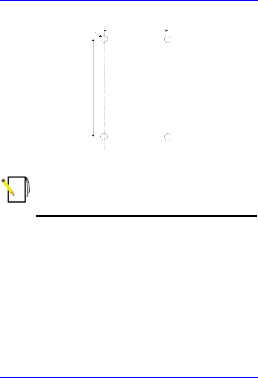
Hardware Installation Manual Installing the SPR
02030311-03 Airspan Networks Ltd. 8-9
.
58mm
8mm
99mm
Figure 8-7: SPR mounting bracket dimensions for the four fixing holes
Note: Airspan does not provide screws for attaching the mounting bracket to
the wall. The screw size depends on the structure of the building to which the
bracket is to be attached. When selecting screw sizes, consideration must be
given to the weight of the SPR and load that may be induced in windy
conditions.
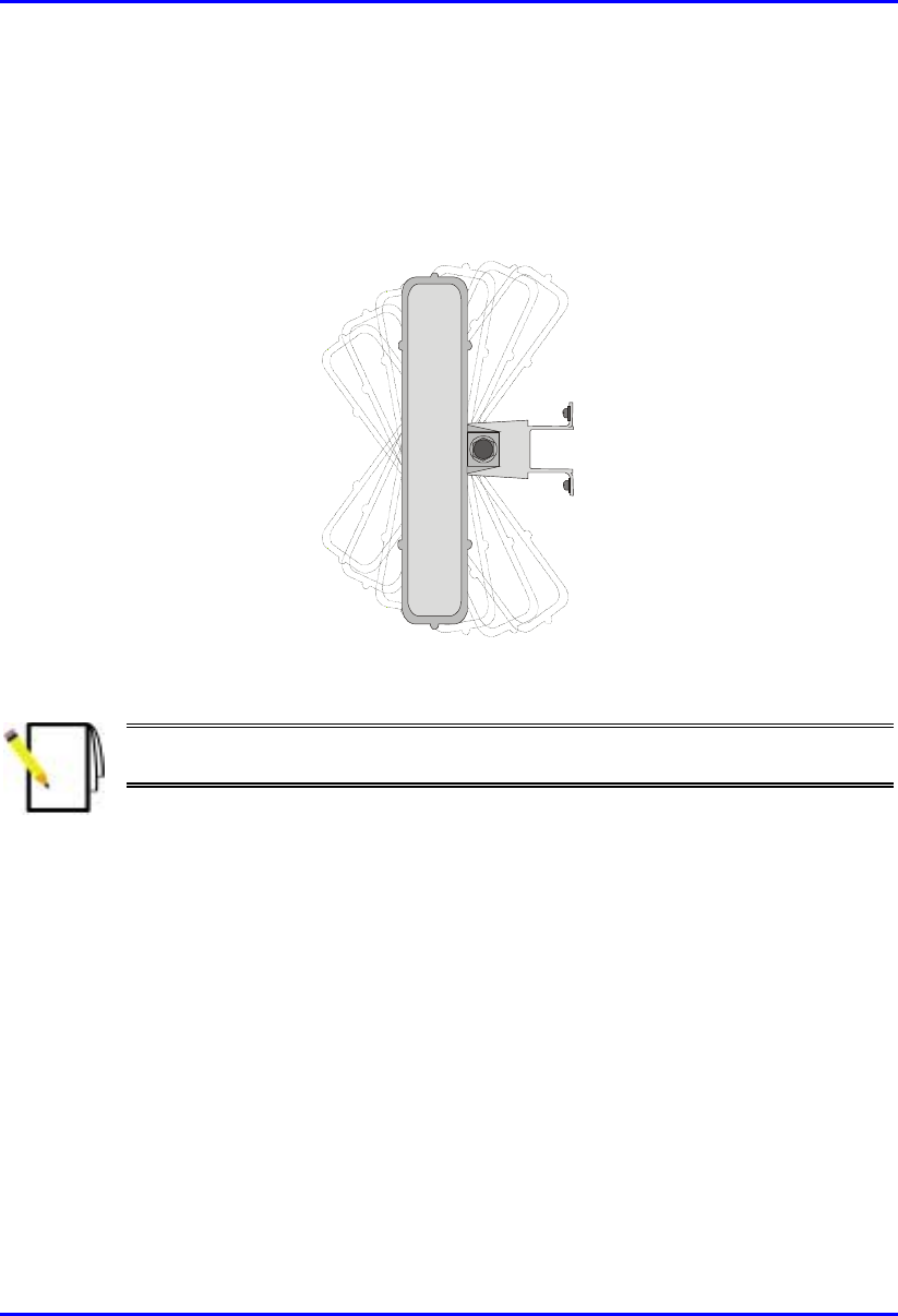
Installing the SPR Hardware Installation Manual
8-10 Airspan Networks Ltd. 02030311-03
3. Adjust the horizontal positioning of the SPR, and then fasten tight the two
stainless-steel bolts.
Rotation is restricted to the horizontal plane only. The permissible rotation is
shown in Figure 8-8.
Figure 8-8: Horizontal rotation of the SPR
Note: A thread-locking compound is to be used to prevent the bolts working
loose.
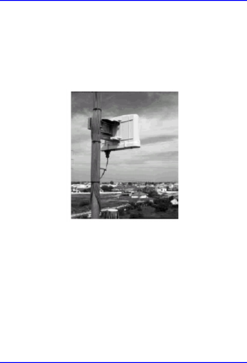
Hardware Installation Manual Installing the SPR
02030311-03 Airspan Networks Ltd. 8-11
8.4.3. Pole-Mounting
The SPR can be mounted on a pole (see Figure 8-9). Pole mounting allows the SPR
to be adjusted in the horizontal as well as the vertical plane. The pole-mounting
bracket assembly is designed to support the SPR on a round pole of 45 mm in
diameter.
Figure 8-9: Mounted SPR
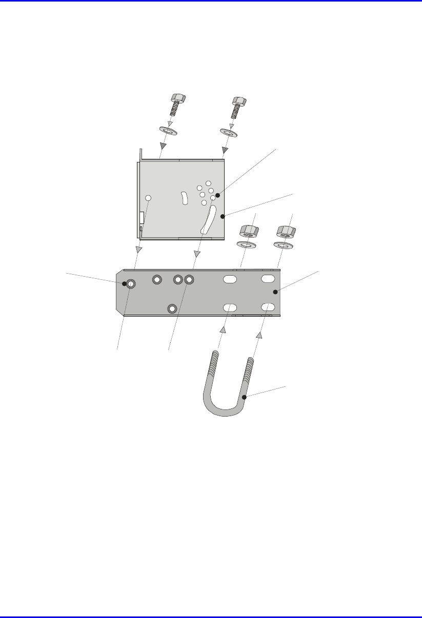
Installing the SPR Hardware Installation Manual
8-12 Airspan Networks Ltd. 02030311-03
To mount the SPR on a pole:
1. Attach the mounting bracket to the SPR using two stainless steel bolts.
Pivot Hole
‘U’ Bolt
Locking Holes
BSR mounting
Bracket
Clamping Bracket
Figure 8-10: SPR mounting bracket assembly
2. Attach the clamping bracket to the mounting bracket using two M8 stainless
bolts.
3. Attach the Clamping bracket to the pole by placing the U-bolt around the pole,
and then inserting the U-bolt through the Clamping bracket and securing it by
screwing the two bolts on the U-bolt.
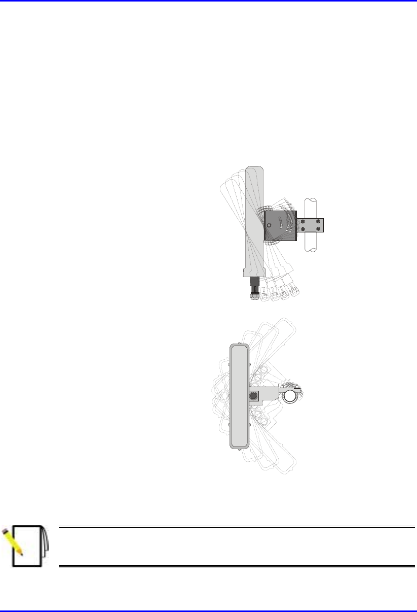
Hardware Installation Manual Installing the SPR
02030311-03 Airspan Networks Ltd. 8-13
4. Adjust the vertical position of the SPR. Lock the SPR at the desired position by
inserting the locking bolt in the desired position. Once the correct angle has been
set both bolts must be tightened to lock the SPR bracket in place.
5. Adjust the horizontal position of the SPR by rotating the SPR about the pole, and
then tighten the U-bolt.
SPR positioning is obtained in two planes by adjustment of the mounting bracket
assembly a shown in Figure 8-11.
Rotation about the
mounting pole
Rotation about the
mounting bracket
Figure 8-11: SPR GPS orientation in vertical (top figure) and horizontal plane (lower
figure)
Note: A thread-locking compound is to be used to prevent the bolts working
loose. A loop should be left in the cable for maintenance purposes and to
prevent the cable weight being taken directly on the connector.
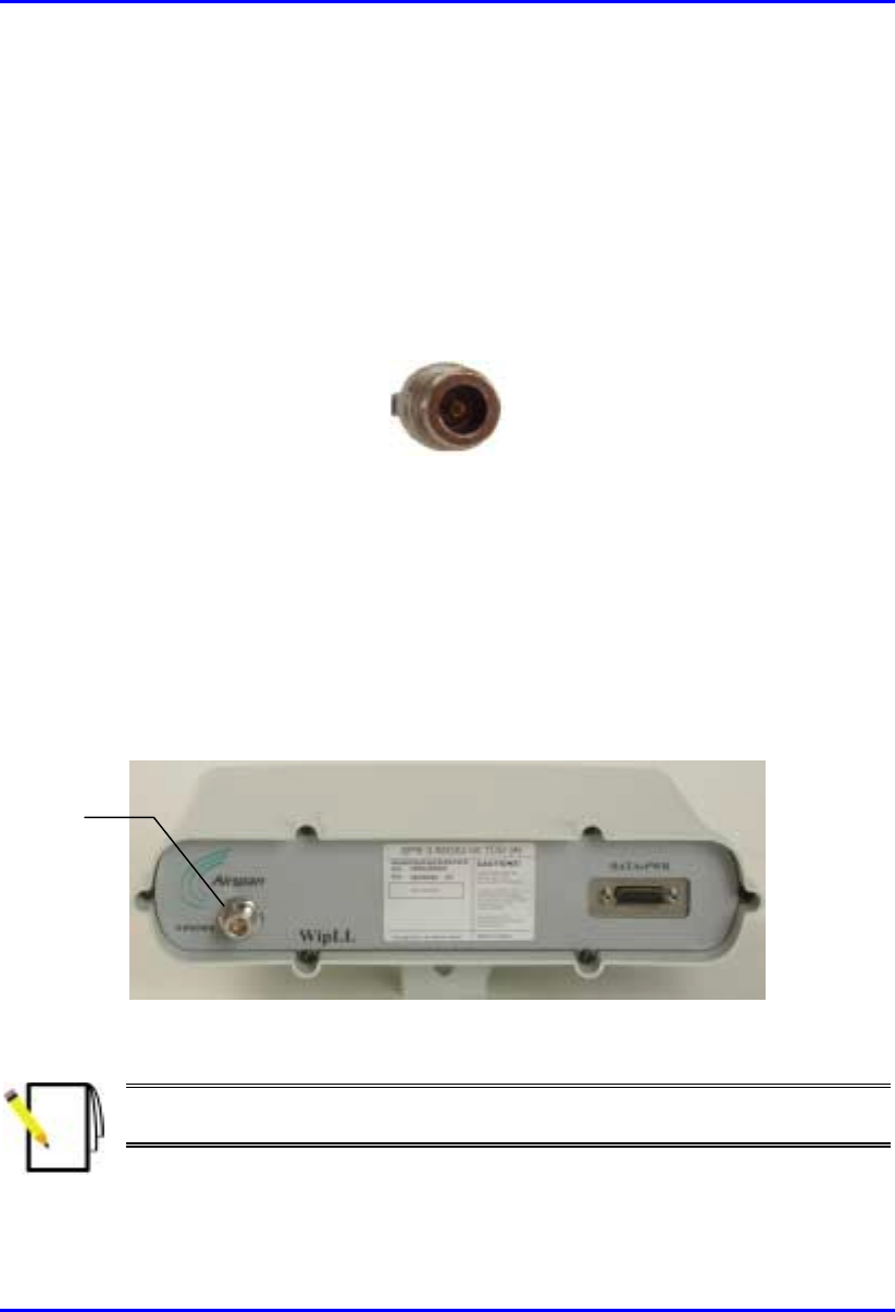
Installing the SPR Hardware Installation Manual
8-14 Airspan Networks Ltd. 02030311-03
8.5. Connecting an External Third-Party
Antenna (Optional)
The SPR model with an N-type connector can be connected to an external antenna.
The addition of an external antenna allows greater RF sector coverage than the
standard SPR internal antenna models (i.e., 60°).
! Connector: N-type male
Figure 8-12: Example of an N-type connector
! Cable: RF
To connect the SPR to an external antenna:
1. Attach the N-type male connector to the N-type receptacle located on the SPR’s
front panel.
2. Attach the other end of the cable to the external antenna.
Figure 8-13: SPR model with N-type connector for attaching an external antenna
Note: Airspan supplies unterminated cables for N-type connectors. Refer to
Appendix B, “Cable Crimping" for N-type cable crimping.
N
-type connector
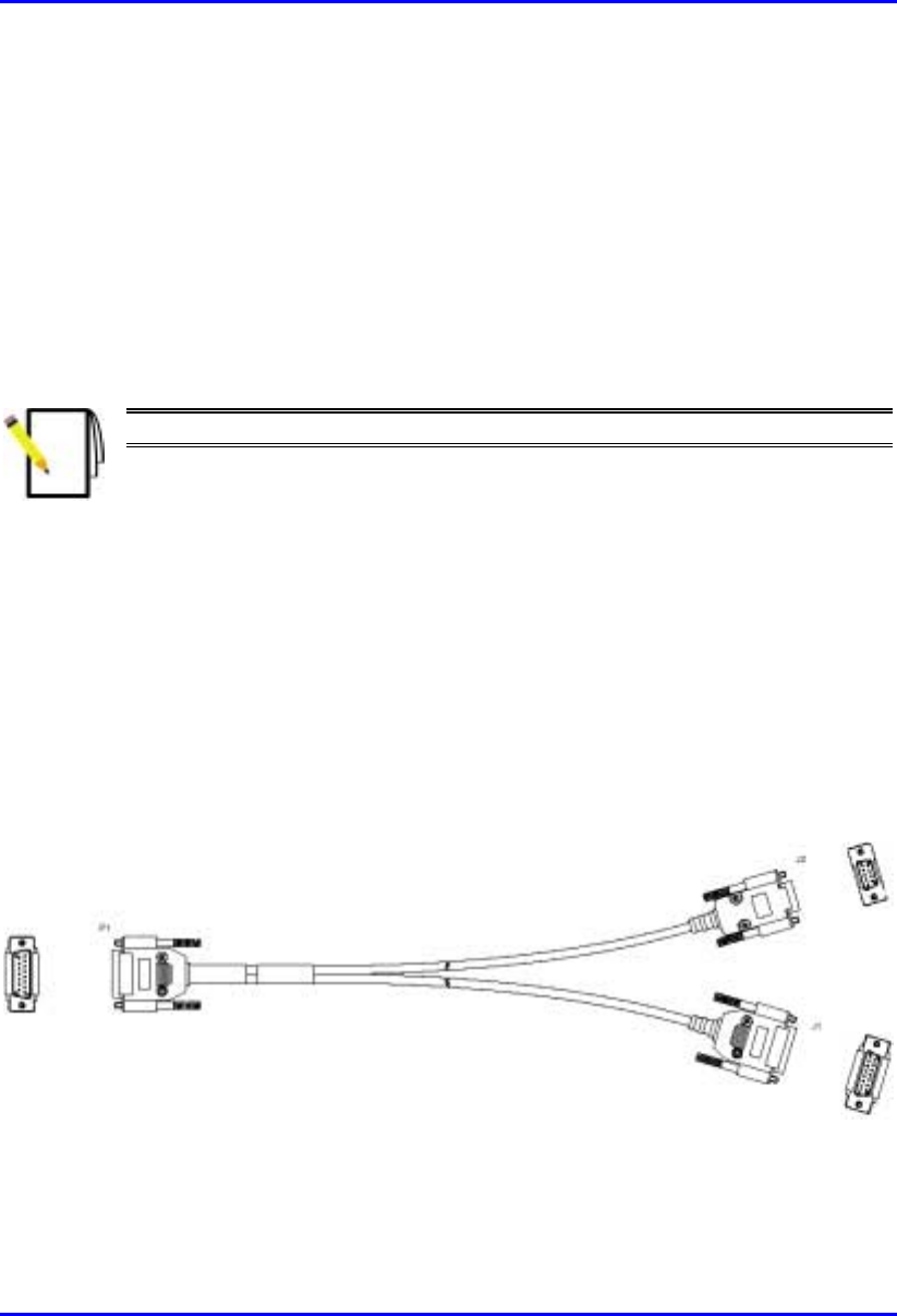
Hardware Installation Manual Installing the SPR
02030311-03 Airspan Networks Ltd. 8-15
8.6. Connecting to a PC for Initial Serial
Configuration
To configure an SPR, you need to connect a PC running the WipLL network
management system (WipConfig) to the SPR. The SPR’s 15-pin D-type port
provides serial interface to a PC for SPR initial configuration. This port uses 9 of its
15 pins for serial interface; the remaining pins are used for interfacing with the SDA
with which the SPR remains connected. To connect the SPR to the management
station (i.e., PC) and the SDA, a Y-cable (splitter) is used.
Note: SPR configuration is performed while the SDA is connected to the SPR.
The SPR-to-PC and SDA cable connections for SPR serial configuration are as
follows:
! Connectors:
! SPR: 15-pin D-type male (only 9-pins used)
! PC: 9-pin D-type (RS-232)
! SDA: 15-pin D-type male
! Cable: straight-through Y-cable
Figure 8-14: Y-Cable (P1 for SPR; J1 for SDA; J2 for PC’s serial port)

Installing the SPR Hardware Installation Manual
8-16 Airspan Networks Ltd. 02030311-03
! Connector pinouts: Table 8-2 displays the connector pinouts for the 15-pin D-
type connectors at the SPR and SDA, and the 9-pin D-type connector at the PC
management station.
Table 8-2: Y-cable connector pinouts for SPR-to-PC serial cable connection
SPR (15-pin D Type)
P1
SDA (15-pin D Type)
J1
PC (RS-232)
J2
Pin Function Pin 9-Pin Function
1 0 VDC 1 0 VDC 1
2 +48 VDC 2 +48 VDC 2 Tx
3 Ethernet Tx+ 3 Ethernet Tx+ 3 Rx
4 Ethernet Tx- 4 Ethernet Tx- 4
5 Ethernet Rx+ 5 Ethernet Rx+ 5 GND
6 Ethernet Rx- 6 Ethernet Rx- 6
7 Ho
p
S
y
nc+ 7 Ho
p
S
y
nc+ 7
8 Ho
p
S
y
nc- 8 Ho
p
S
y
nc- 8
9
N
C 9
N
C9
10
N
C 10
N
C
11
N
C 11
N
C
12
N
C 12
N
C
13
N
C 13
N
C
14 RS232 Rx 14
N
C
15 RS232 Tx 15
N
C
The Y-cable connector pin assignments is displayed in Figure 8-15.
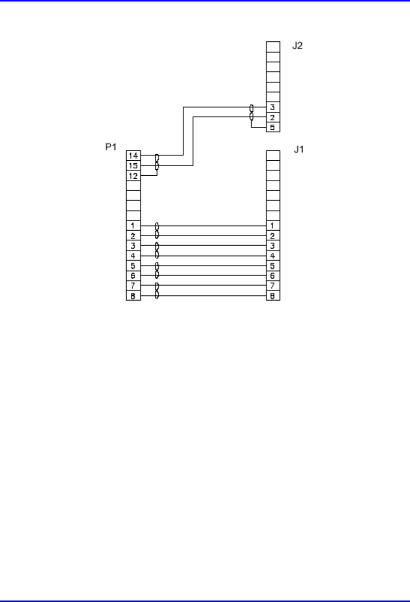
Hardware Installation Manual Installing the SPR
02030311-03 Airspan Networks Ltd. 8-17
Figure 8-15: Y-cable connector pin assignment
To connect the SPR to the PC and SDA for serial configuration:
1. Connect the 15-pin D-type male connector (P1), at the one end of the Y-cable,
to the SPR, as displayed in Figure 8-16.
2. Connect the 15-pin D-type male connector (J1), at the other end of the Y-cable,
to the SDA, as displayed in Figure 8-16.
3. Connect the 9-pin D-type (RS232) connector (J2), at the other end of the Y-
cable, to the PC, as displayed in Figure 8-16.
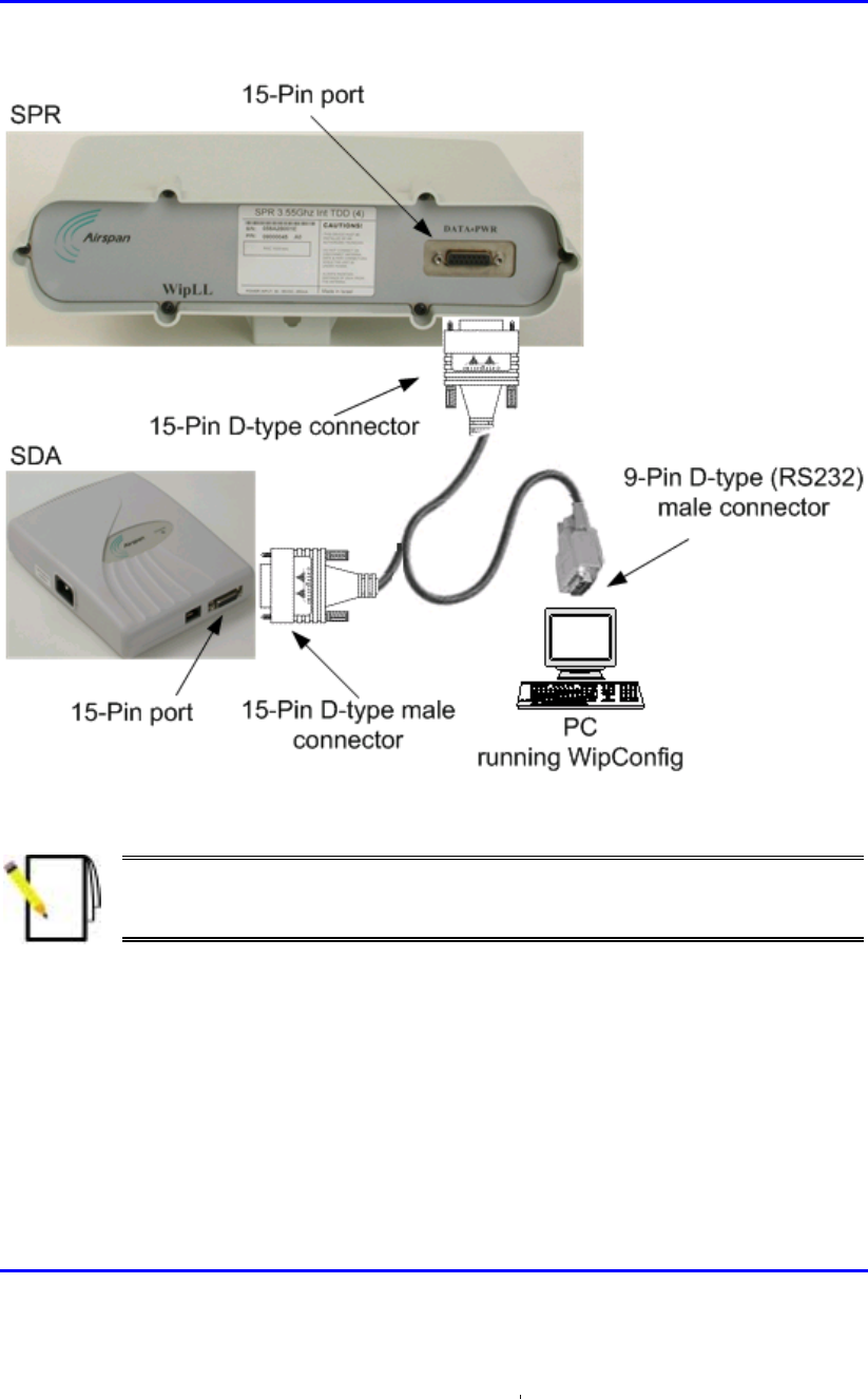
Installing the SPR Hardware Installation Manual
8-18 Airspan Networks Ltd. 02030311-03
Figure 8-16: SPR cable connections for serial configuration
Note: For performing SPR initial configuration using WipLL’s management
applications, refer to Airspan’s WipConfig User’s Guide or WipConfig PDA
User’s Guide.
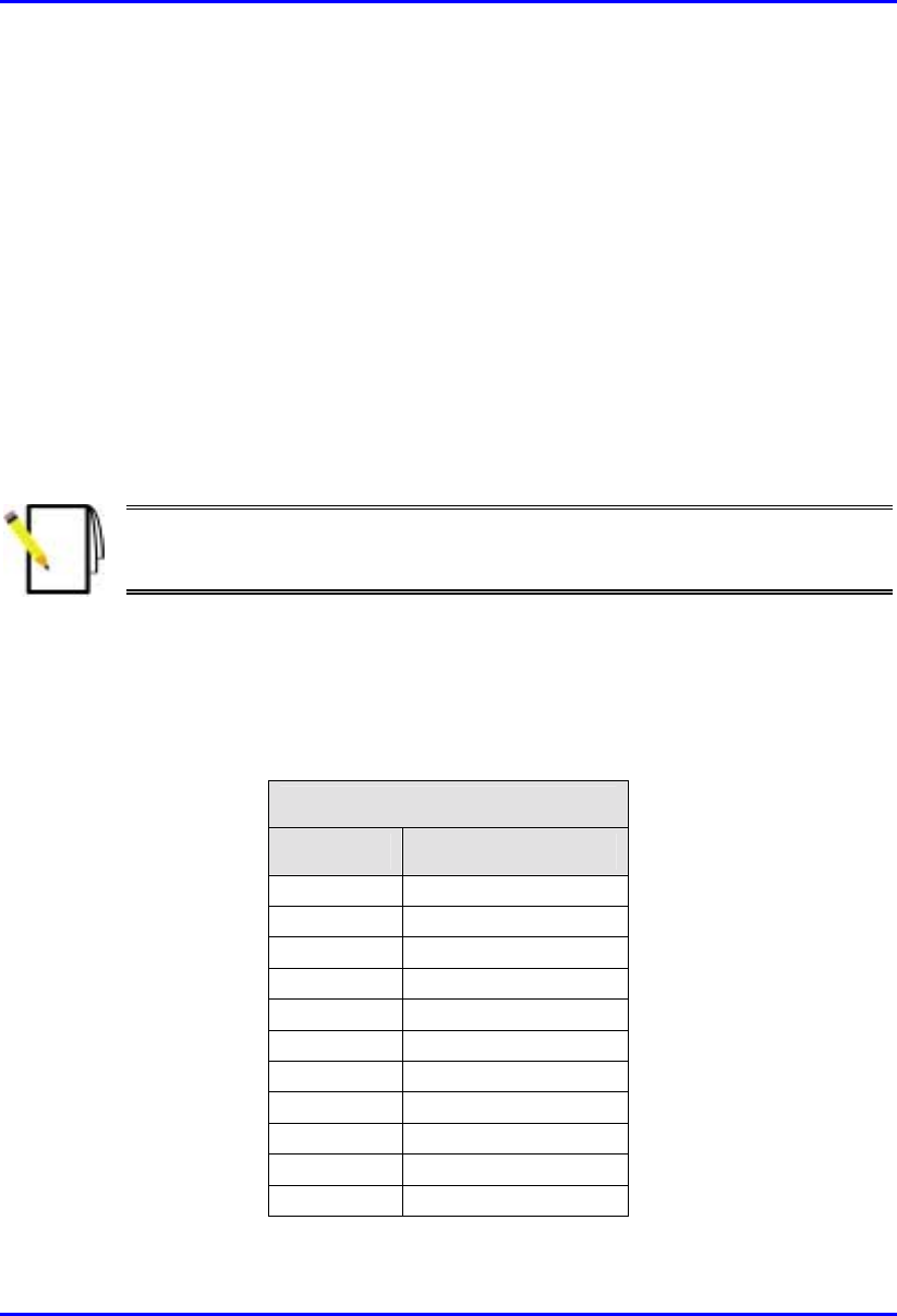
Hardware Installation Manual Installing the SPR
02030311-03 Airspan Networks Ltd. 8-19
8.7. Connecting to the SDA
The SPR connects to the subscriber’s PCs/network through the SDA. To connect the
SPR to the SDA, you need to connect the SPR’s 15-Pin D-type port to the SDA’s
15-pin D-type port by a CAT-5e cable.
The SPR-to-SDA cable connection configurations is as follows:
! Connectors:
! SPR: 15-pin D-type male (only 8 pins are used)
! SDA: 15-pin D-type male (only 8 pins are used)
Note: Airspan supplies unterminated CAT-5e cables. Refer to the cable
crimping procedures for 15-Pin D-type connectors detailed in Appendix B,
“Cable Crimping".
! Cable: straight-through 10Base-T Ethernet UTP 4 Pair CAT-5e outdoor type
(24 AWG)
! Connector pinouts:
! SPR:
15-Pin D-type
Pin Function
1 + 48VDC
2 - 48VDC
3 +Tx
4 -Tx
5 +Rx
6 -Rx
7 +S
y
nc.
8 -S
y
nc.
9
N
ot connected
(
NC
)
10
N
C
11
N
C
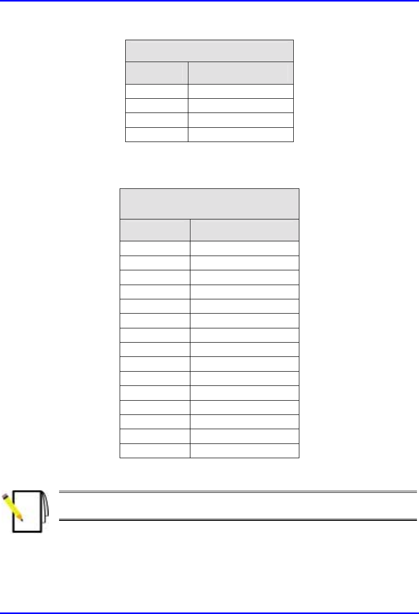
Installing the SPR Hardware Installation Manual
8-20 Airspan Networks Ltd. 02030311-03
15-Pin D-type
Pin Function
12
N
C
13
N
C
14
N
C
15
N
C
! SDA:
SDA-1, SDA-4H, SDA-4S
(15-Pin D-type)
Pin Function
1 +48v
2 -48v
3 +RX
4
–
RX
5 +TX
6
–
TX
7
N
ot connected
(
NC
)
8
N
C
9
N
C
10
N
C
11
N
C
12
N
C
13
N
C
14
N
C
15
N
C
Note: The SDA connector pinouts are the same for all SDA models (SDA-1,
SDA-4H, SDA-4S, SDA-4S/VL, SDA-4S/1H3L, and SDA-4S/VL/1H3L).

Hardware Installation Manual Installing the SPR
02030311-03 Airspan Networks Ltd. 8-21
Warning: To avoid electrical shock, before connecting the SPR to the SDA,
ensure that the SDA is not connected to the power supply.
To connect the SPR to the SDA:
1. Attach the 15-pin D-type connector, at one end of the cable, to the SPR’s 15-pin
D-type port labeled DATA POWER SYNC, as displayed in Figure 8-17.
2. Attach the 15-pin D-type connector, at the other end of the cable, to the SDA’s
15-pin D-type port, as displayed in Figure 8-17.
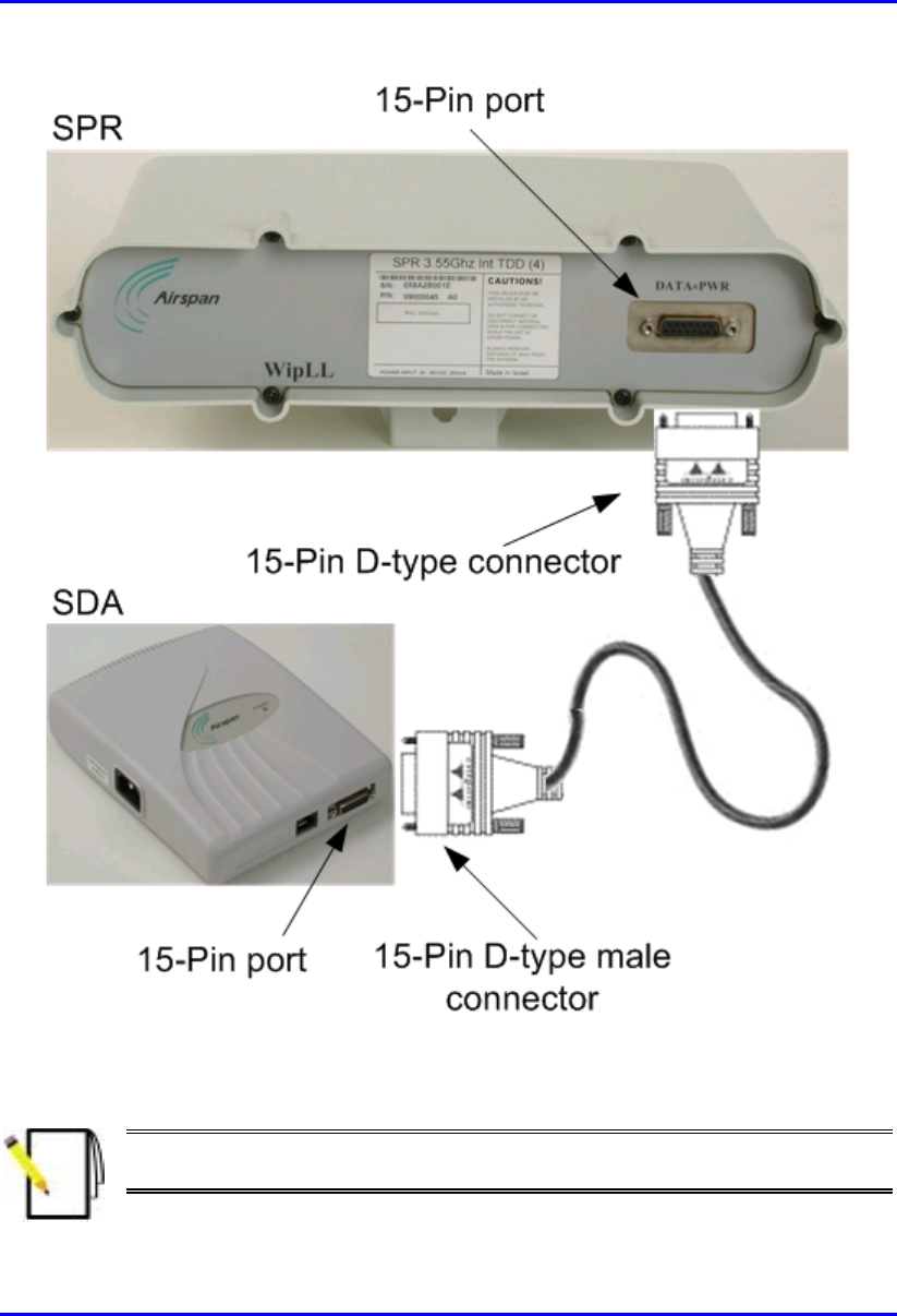
Installing the SPR Hardware Installation Manual
8-22 Airspan Networks Ltd. 02030311-03
Figure 8-17: SPR-to-SDA cable connections
Note: The maximum cable length permissible between the SPR and SDA is
100 meters.

Hardware Installation Manual Installing the SPR
02030311-03 Airspan Networks Ltd. 8-23
8.8. Connecting Power
The SPR receives, through its 15-pin D-type port, its power supply from the SDA.
In turn, the SDA connects to an external power adapter from where it receives
power. The SDA provides 48 VDC nominal power to the SPR (minimum of 30
VDC: maximum of 55 VDC).
Note: For a description of the procedure for connecting power to the SDA, see
Chapter 9, “Installing the SDA”.

02030311-03 Airspan Networks Ltd. 9-1
Installing the SDA
Installing the SDAInstalling the SDA
Installing the SDA
This chapter describes the installation of the WipLL Subscriber Data Adapter
(SDA) at the subscriber's premises.
This chapter includes the following chapters:
! Overview
! Physical Dimensions and Basic Design
! Mounting the SDA
! Desktop-Mounting
! Wall-Mounting
! Connecting to the SPR
! Connecting to the Subscriber’s Ethernet Network
! Connecting to PCs
! Connecting to a Hub
! Connecting to a VoIP Network
! Connecting AC Power
! LED Display
! SDA-4H
! SDA-4S Models
9

Installing the SDA Hardware Installation Manual
9-2 Airspan Networks Ltd. 02030311-03
9.1. Overview
The SDA is an Ethernet hub/LAN switch that provides the SPR with DC power,
lightening protection, and Ethernet connectivity to the subscriber’s PCs/network.
The SDA connects to the SPR by a CAT-5e cable.
The SDA provides 10/100BaseT connectivity (depending on the SDA model) to the
subscriber’s PCs or network (up to four PCs depending on the SDA model).
The SDA is located inside the subscriber's premises, typically mounted on a wall or
simply placed on a desktop.
The SDA is available in six models:
! SDA-1: This is a hub that provides one 10BaseT interface (RJ-45 port) with the
subscriber’s PC and/or network (via a hub or LAN switch).
! SDA-4H: This is a hub and provides four 10BaseT ports for interfacing with the
subscriber’s PCs/network. In addition, one of the 10BaseT ports provides
crossover configuration for crossover-cable connection for interfacing with, for
example, other hubs.
! SDA-4S models: Integrated LAN switches, providing four 10/100BaseT
interfaces with the subscriber’s PCs/network.
! (standard): Standard integrated LAN switch, providing four 10/100BaseT
interfaces to the subscriber’s computers.
! SDA-4S/VL: Provides VLANs between its ports and the SPR, ensuring
privacy between users of different ports (i.e., multi-tenant VLAN security).
For example, all users connected to Port 1 do not “see” users connected to
Port 2.
! SDA-4S/1H3L: Provides a high priority port (left-most port) for VoIP
traffic.
! SDA-4S/VL/1H3L: Combines the functionality of the SDA-4S/VL and
SDA-4S/1H3L models (VLAN for each port and a high priority port for
VoIP).
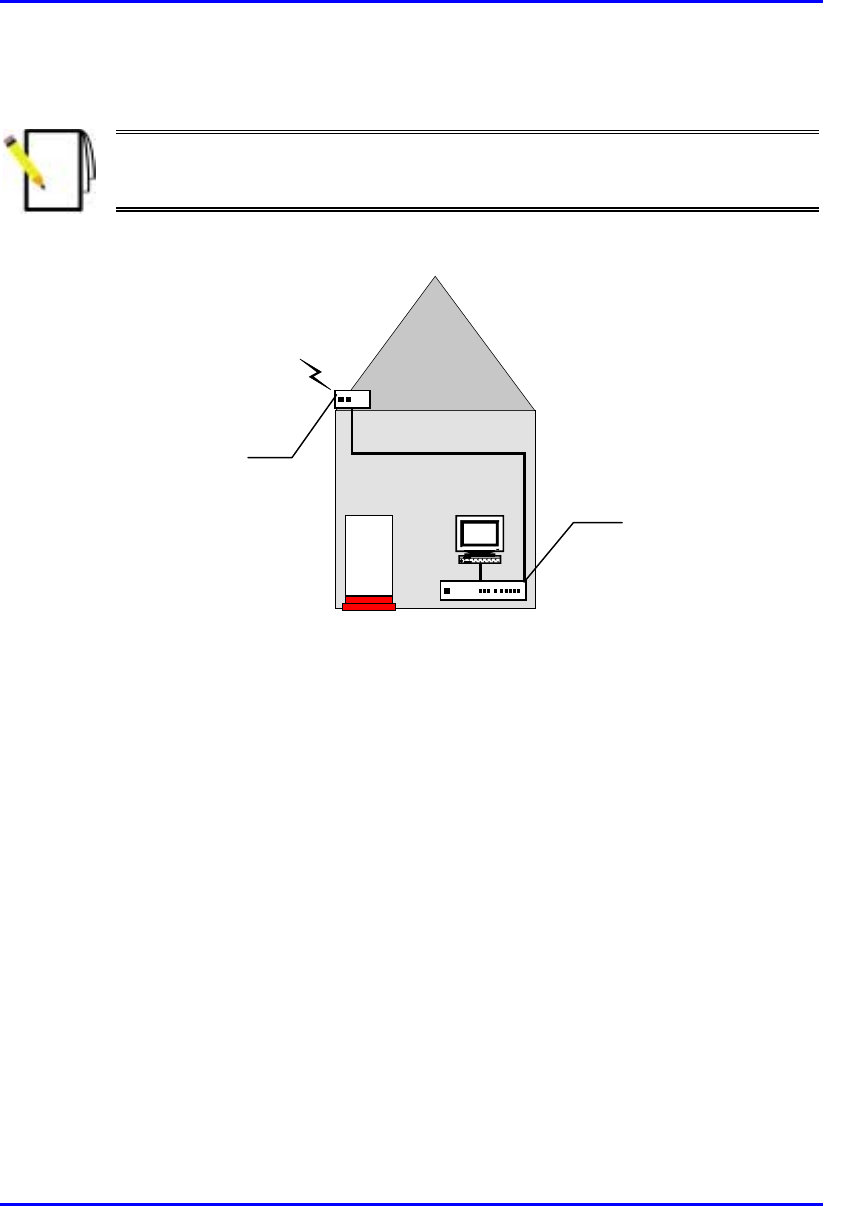
Hardware Installation Manual Installing the SDA
02030311-03 Airspan Networks Ltd. 9-3
Figure 9-1 displays a typical setup of the SPR and SDA at the subscriber's premises.
Note: The SDA can also be installed at a base station that has only one BSR.
This SDA replaces the need for the BSDU, and provides power and
connectivity to the single BSR.
RF link
CAT-5e
PC
Figure 9-1: Typical SPR and SDA location and connections at subscriber's premises
Subscriber Data
Adapter (SDA)
located inside
Subscriber Premises
Radio (SPR) located
on the roof
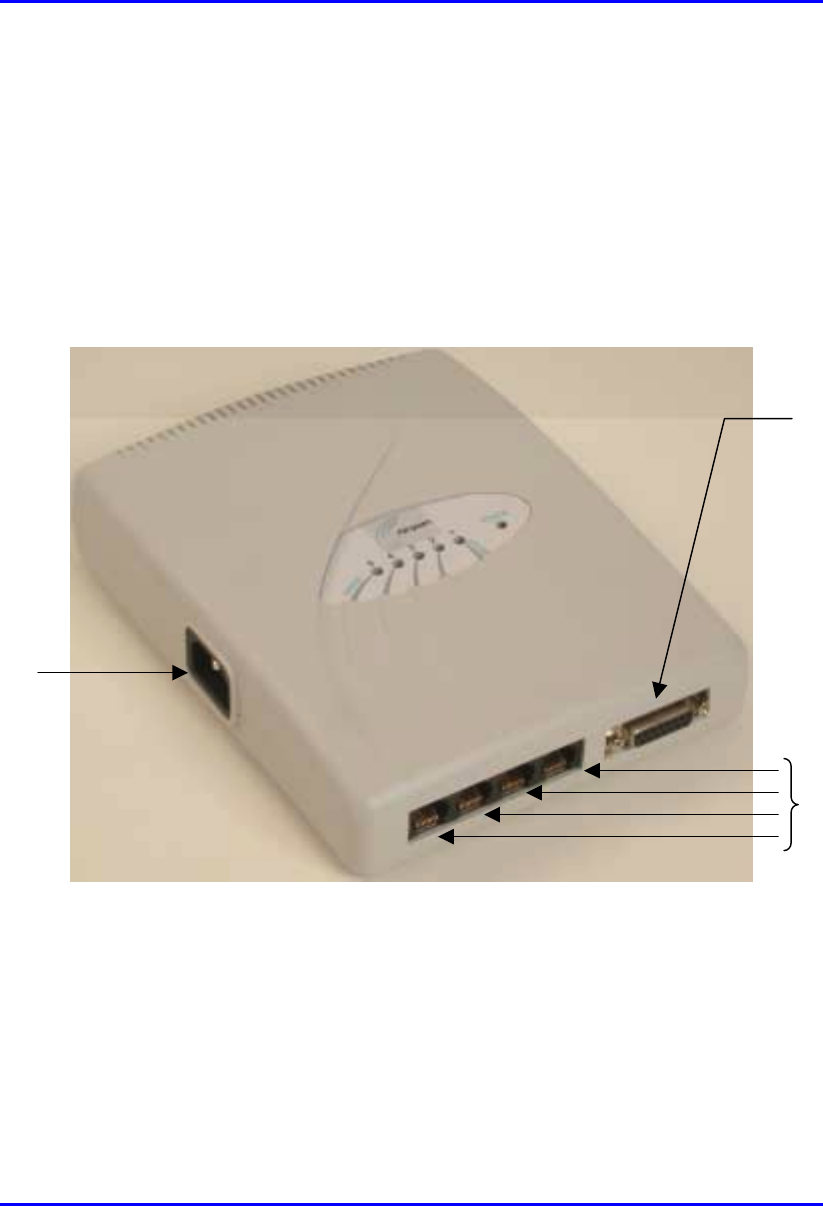
Installing the SDA Hardware Installation Manual
9-4 Airspan Networks Ltd. 02030311-03
9.2. Physical Dimensions and Basic Design
The SDA is encased in a chassis. The chassis front panel provides access to the
SDA’s communication ports. The left-side of the chassis provides a power connector
port for connection to an external power adapter. The SDA’s bottom panel provides
holes for mounting the SDA on a wall
Figure 9-2 displays the SDA-4S models and the SDA-4H.
Figure 9-2: SDA-4S models and SDA-4H (front, side, and top panels)
15-pin D-type
p
ort
10/100BaseT
p
orts
Power
connector port
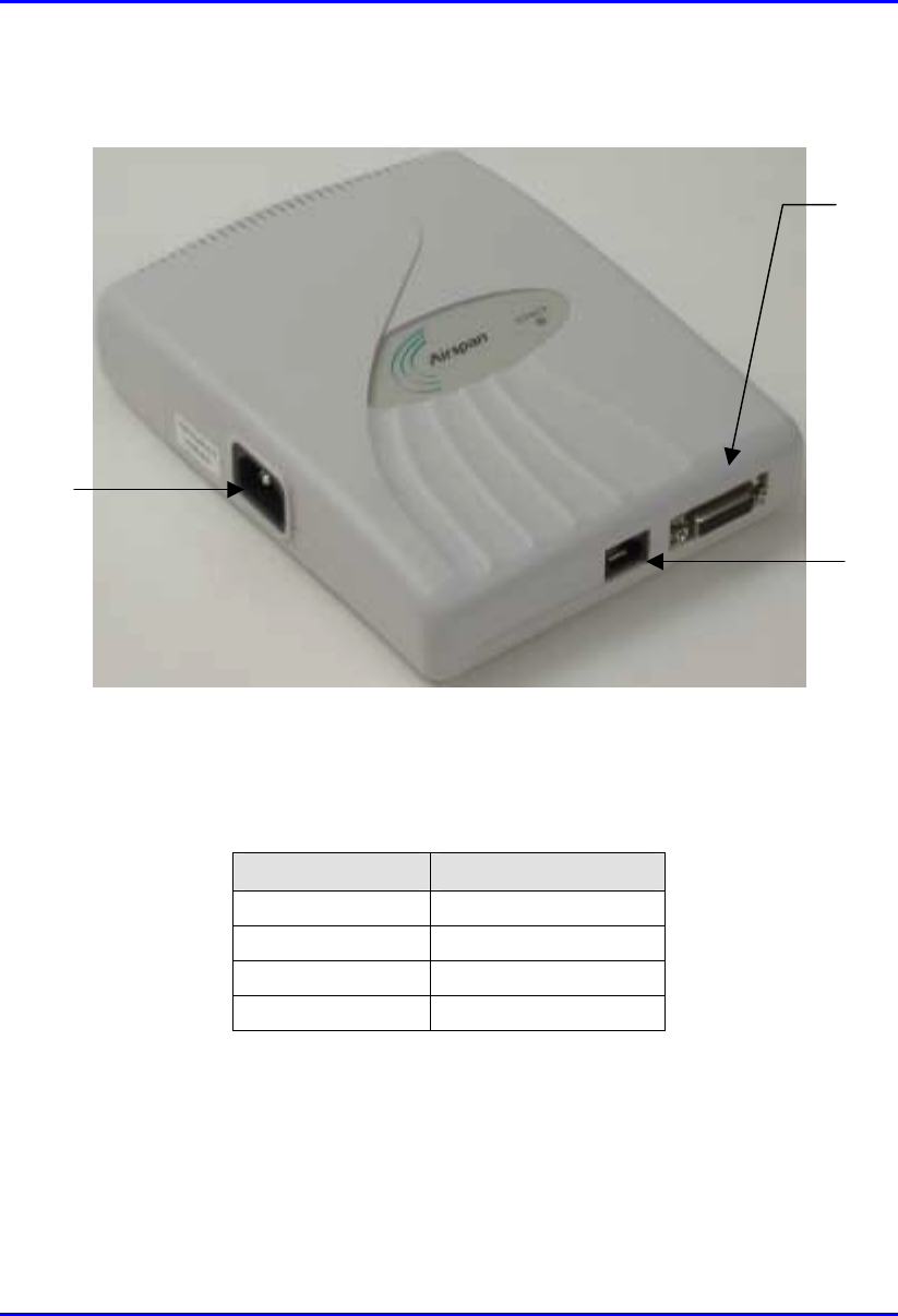
Hardware Installation Manual Installing the SDA
02030311-03 Airspan Networks Ltd. 9-5
Figure 9-3 displays the SDA-1 model.
Figure 9-3: SDA-1 (front, side, and top panels)
The SDA’s physical dimensions are described in Table 9-1
Table 9-1: SDA Physical Dimensions
Parameter Value
Height 200 mm (7.87 inches)
Width 150 mm (5.9 inches)
Depth 40 mm (1.57 inches)
Weight 0.53 kg
15-Pin D-type
p
ort
RJ-45 port
(10BaseT)
Power connector
p
ort
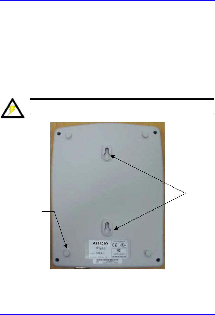
Installing the SDA Hardware Installation Manual
9-6 Airspan Networks Ltd. 02030311-03
9.3. Mounting the SDA
The SDA can be wall or desk mounted.
9.3.1. Desktop-Mounting
For desk mounting (horizontal mounting), the chassis’ bottom panel provides four
rubber feet on each corner.
Warning: For desk mounting, do not place the SDA on a carpeted surface
where airflow is restricted and a fire hazard may result.
Figure 9-4: SDA - rear panel
Mounting
brackets
Rubber feet
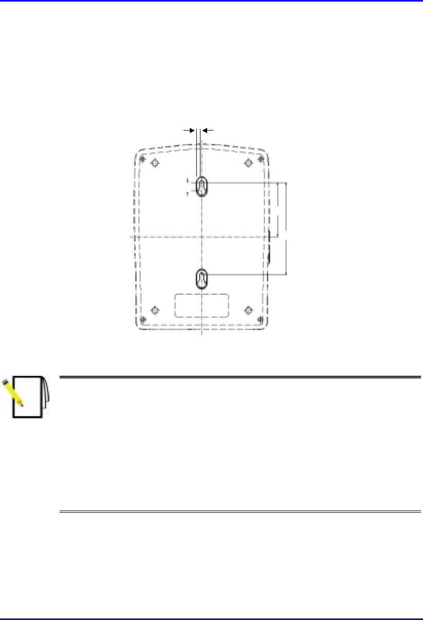
Hardware Installation Manual Installing the SDA
02030311-03 Airspan Networks Ltd. 9-7
9.3.2. Wall-Mounting
For SDA wall mounting, two mounting hooks are molded into the chassis’ bottom
panel (see Figure 9-4). The dimensions of the SDA’s wall-mounting hooks, located
on the chassis bottom panel, are displayed in Figure 9-5.
5 mm
59
100
9
Figure 9-5: SDA mounting footprint details
Notes:
1) Airspan does not supply screws for wall mounting as the size and type o
f
screws depends on the type of wall at the subscriber’s premises
2) For reasons of safety both fixing points must be utilized when mounting the
unit.
3) The SDA is supplied with a 1-metre AC power lead assembly. Therefore,
the unit must be located within reachable distance of the customer's mains
power outlet.
4) The cable must be dressed tidily and not be taught or pose a trip hazard
when connected.
5) The maximum cable run between an SDA and an SPR is 100 meters.

Installing the SDA Hardware Installation Manual
9-8 Airspan Networks Ltd. 02030311-03
9.4. Connecting to the SPR
The SDA’s 15-pin D-type port connects to the SPR’s 15-pin D-type port by a
CAT-5e cable.
Note: For a detailed description on connecting the SDA to the SPR, see
Chapter 8, “Installing the SPR”.
9.5. Connecting to the Subscriber’s Ethernet
Network
The SDA provides RJ-45 port(s) for Ethernet connectivity to the subscriber’s
PCs/network. The number of Ethernet ports and the speed of the Ethernet connection
depend on the SDA model. Table 9-2 describes the number of ports and
transmission speeds supported by the various SDA models.
Table 9-2: Number of Ports and Transmission Speed of SDA Models
SDA Model RJ-45 Ports Speed (Mbps)
SDA-1 1 10
SDA-4H 4 10
SDA-4S models
(SDA-4S; SDA-4S/VL; SDA-4S/1H3L;
SDA-4S/VL/1H3L)
4 10/100
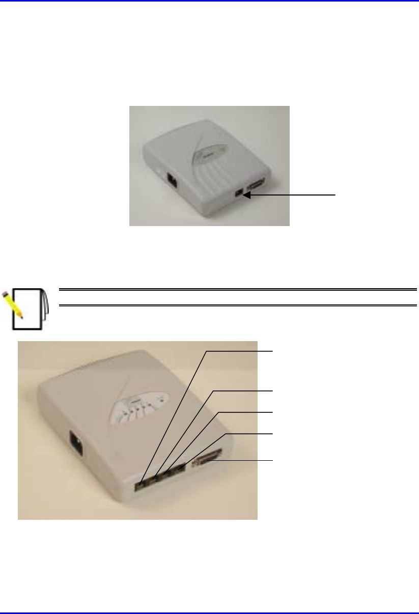
Hardware Installation Manual Installing the SDA
02030311-03 Airspan Networks Ltd. 9-9
The following list describes the location of the Ethernet ports for the various SDA
models:
! SDA-1: one RJ-45 port (see Figure 9-6)
Figure 9-6: SDA-1 with one Ethernet port
! SDA-4H: four RJ-45 ports (see Figure 9-7).
Note: The left-most port (J5) is a crossover port.
R-J45 connector (J5)
- cross over
R
-J45 connector
(
J4
)
R-J45 connector (J3)
R-J45 connector (J2)
D-type connector (J1)
Figure 9-7: SDA-4H with four Ethernet ports
RJ-45 port
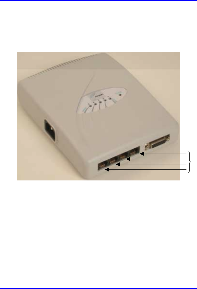
Installing the SDA Hardware Installation Manual
9-10 Airspan Networks Ltd. 02030311-03
! SDA-4S models (SDA-4S, SDA-4S/VL, SDA-4S/1H3L, and SDA-
4S/VL/1H3L): four 10/100BaseT RJ-45 ports. These ports support 10/100 Mbps
autosensing, and MDI/MDI-X automatic crossover. This allows you to connect
straight-through or crossover CAT-5 cables to these ports.
Figure 9-8: SDA-4S RJ-45 Ethernet Ports
10/100BaseT
RJ-45 ports

Hardware Installation Manual Installing the SDA
02030311-03 Airspan Networks Ltd. 9-11
9.5.1. Connecting to PCs
The SDA connects to the subscriber’s PC(s) through the SDA’s Ethernet port (RJ-
45).
Note: To avoid electrical or fire hazard, ensure that the data connections to
the SDA is made prior to connecting the power supply.
The SDA-to-subscriber PC cable configurations are as follows:
! Connector: 8-pin RJ-45
! Cable: straight-through Ethernet cable
! Connector Pinouts:
RJ-45:
SDA-1, SDA-4H (J2, J3, J4), SDA-4S
RJ-45 crossover cables:
SDA-4H (J5)
Pin Function Pin Function
1 +RX 1 +Tx
2 -RX 2 -Tx
3 +TX 3 +Rx
4
N
C4
N
C
5
N
C5
N
C
6 -TX 6 -Rx
7
N
C7
N
C
8
N
C8
N
C
To connect the SDA to the subscriber’s PC(s):
1. Connect the 8-pin RJ-45 male connector, at the one end of the Ethernet cable, to
the SDA’s RJ-45 Ethernet port (see Figure 9-9).
2. Connect the
8-pin RJ-45 male connector, at the other end of the Ethernet cable,
to the subscriber’s PC (or device). (See Figure 9-9.)
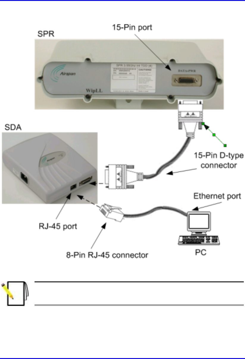
Installing the SDA Hardware Installation Manual
9-12 Airspan Networks Ltd. 02030311-03
Figure 9-9: SDA-to-PC Cable Connections
Note: The SDA-4S RJ-45 ports support MDI/MDI-X automatic crossover. This
means that straight-through or crossover CAT-5 cables can be connected to
these ports.

Hardware Installation Manual Installing the SDA
02030311-03 Airspan Networks Ltd. 9-13
9.5.2. Connecting to a Hub
The SDA-4S models and SDA-4H can be connected to another hub (for example,
for daisy chaining). The ports of the SDA-4S models support MDI/MDI-X
automatic crossover, allowing connection of straight-through or crossover cables.
However, for the SDA-4H model, only the left-most RJ-45 port (J5) is a crossover
port (see Figure 9-7).
The SDA-4S and SDA-4H cable configurations for connectivity to a hub, are as
follows:
! Connector: 8-Pin RJ-45
! Cable:
! SDA-4H: crossover-cable
! SDA-4S models: straight-through or crossover cables (due to MDI/MDI-X
ports)
! Connector pinouts: SDA-4H:
SDA-4H
RJ-45 (J5)
Pin Function
1+TX
2-TX
3+RX
4
N
C
5
N
C
6-RX
7
N
C
8
N
C
To connect SDA-4S or SDA-4H to a hub:
1. Connect the RJ-45 male, at one end of the cable, to the SDA-4H’s left-most RJ-
45 port (J5), or any SDA-4S’s RJ-45 port.
2. Connect the RJ-45 male, at the other end of the cable, to the hub.
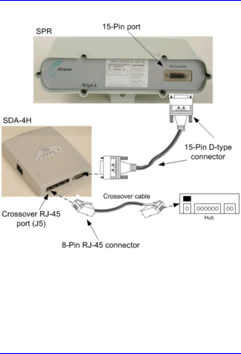
Installing the SDA Hardware Installation Manual
9-14 Airspan Networks Ltd. 02030311-03
Figure 9-10: SDA-4H Crossover Cable Connections to Hub
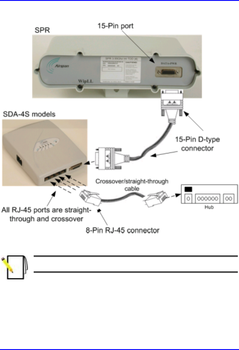
Hardware Installation Manual Installing the SDA
02030311-03 Airspan Networks Ltd. 9-15
Figure 9-11: SDA-4S Crossover/Straight-Through Cable Connections to Hub
Note: The SDA-4S RJ-45 ports support MDI/MDI-X automatic crossover.
Therefore, crossover CAT-5 cables can be connected to any of the ports.

Installing the SDA Hardware Installation Manual
9-16 Airspan Networks Ltd. 02030311-03
9.5.3. Connecting to a VoIP Network
The SDA-4S/1H3L and SDA-4S/VL/1H3L model’s left-most RJ-45 Ethernet port
assigns high priority to VoIP trafic. This port is used to connect to the subscriber’s
VoIP network. This port assigns high priority to VoIP traffic, as opposed to the other
RJ-45 ports, which assigns lower priority.
The cable connections for connecting the SDA-4S/1H3L and SDA-4S/VL/1H3L
models to the subscriber’s VoIP network, are as follows:
! Connector: 8-pin RJ-45 male
! Cable: straight-through or crossover
! Connector pinouts:
RJ-45 (left-most port)
Pin Function
1 +RX
2 -RX
3 +TX
4
N
C
5
N
C
6 -TX
7
N
C
8
N
C
To connect to the VoIP network:
1. Connect the RJ-45 male connector, at the one end of the Ethernet cable, to the
left-most RJ-45 port on the front panel of the SDA-4S/1H3L and SDA-
4S/VL/1H3L chassis (see Figure 9-12).
2. Connect the RJ-45 male connector, at the other end of the cable, to the VoIP
network, for example, to a Residential Gateway (see Figure 9-12).
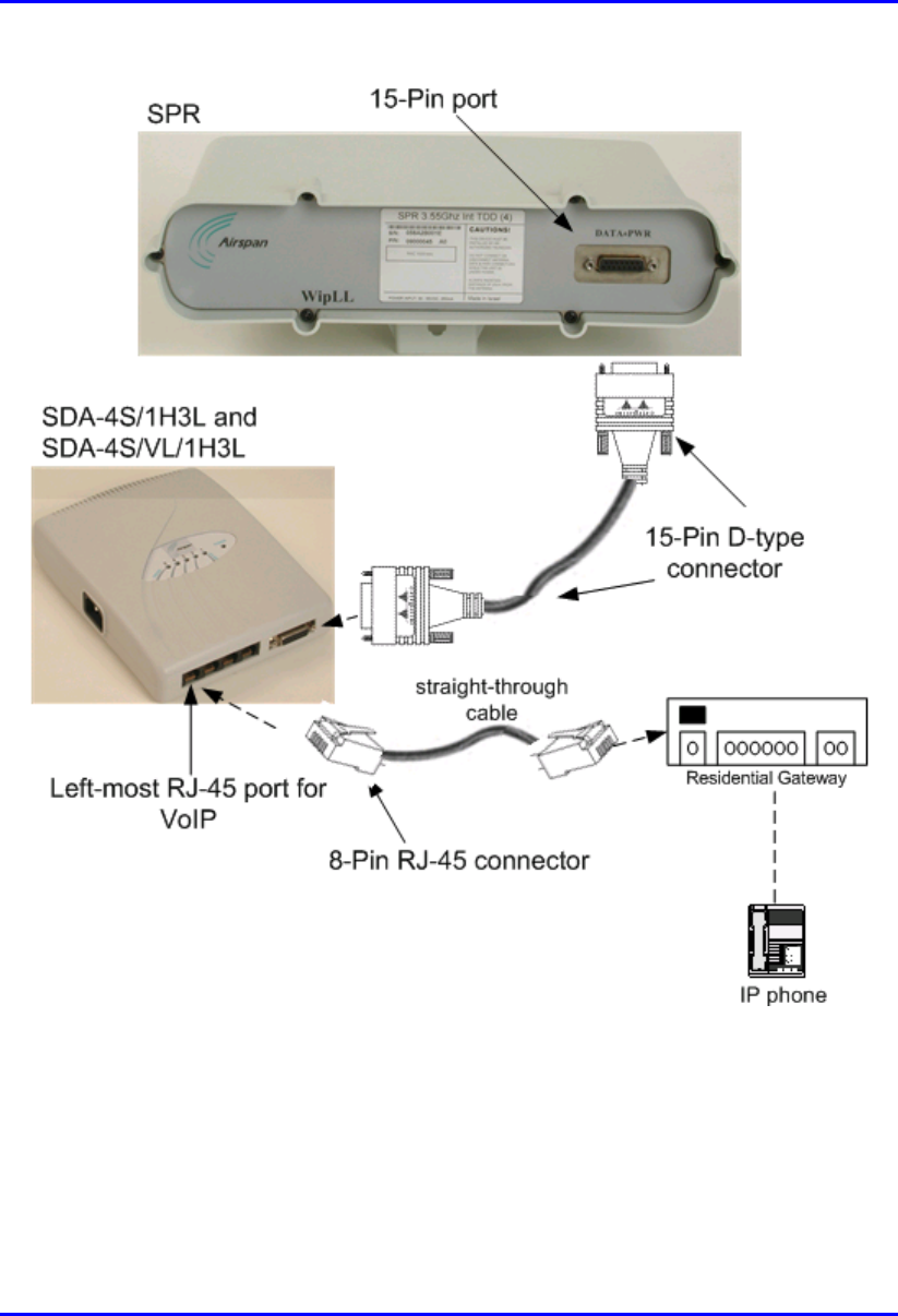
Hardware Installation Manual Installing the SDA
02030311-03 Airspan Networks Ltd. 9-17
Figure 9-12: Connecting VoIP RJ-45 Port (for SDA-4S/1H3L and SDA-4S/VL/1H3L)
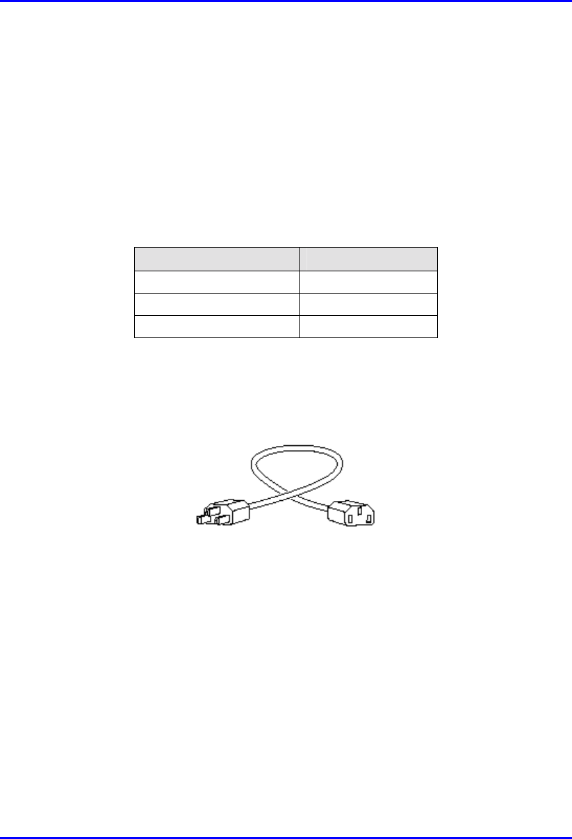
Installing the SDA Hardware Installation Manual
9-18 Airspan Networks Ltd. 02030311-03
9.6. Connecting AC Power
The SDA receives AC power by connecting to a standard 110–240 VAC wall outlet.
In turn, the SDA provides 48 VDC nominal power to the SPR (minimum of 30
VDC: maximum of 55 VDC).
Table 9-3 lists the SDA power supply specifications.
Table 9-3: SDA Power Supply Specifications
Power parameter Units
Voltages 110-240 VAC
Frequency 50/60 Hz
Amps 0.3-0.7A
The following lists the cable connection between the SDA and the power outlet:.
! Connector: AC IEC 320 type (female)
Figure 9-13: Power Chord
! Cable: 3-core 0.7mm² type (maximum length is 1.5 m)
For all SDA models, the power port is located on the left-panel of the chassis, as
displayed in Figure 9-14 for SDA-1, and in Figure 9-15 for SDA-4H and SDA-4S
models.
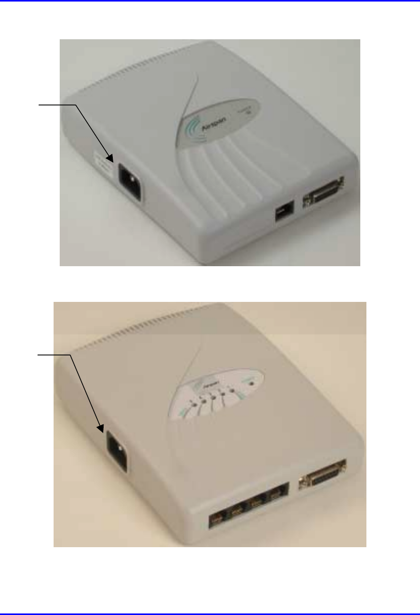
Hardware Installation Manual Installing the SDA
02030311-03 Airspan Networks Ltd. 9-19
Figure 9-14: Location of SDA-1 power port
Figure 9-15: Location of SDA-4S model’s and SDA-4H power port
Power port
Power port
Installing the SDA Hardware Installation Manual
9-20 Airspan Networks Ltd. 02030311-03
Warning: Ensure that plugs fitted to mains power leads for subscriber
premises equipment are compatible with AC mains sockets. Do not replace
plugs on power leads to suit local requirements without first verifying grounding
practice for the country and equipment in question.
Careful consideration must be given to issues including local wiring
requirements, cable color-coding, safety grounding, and circuit protection
requirements.
Prior to connecting to the power outlet, the following pre-connection inspection
should be performed on power sockets:
! Power socket shall be visually inspected to ensure that no other equipment is
connected to the power outlet.
! No damage to the power outlet.
! No water or dampness on or around the power outlet.
! The power outlet shall be checked using a proprietary plug tester such as a
“Martindale Ze” type. Checks are required to verify the earth loop impedance
value and the presence of phase, neutral, and earth connections.
Note: To avoid electrical or fire hazard, ensure that the data connections to
the SDA is made prior to connecting the SDA to the power supply.
To connect the SDA to AC power supply:
1. Plug the power plug female, at the end of the AC power chord, into the power
plug male located omn the left of the SDA chassis (see Figure 9-16).
2. Plug the power plug male, at the other end of the AC power chord, into the wall
power outlet (110-240 VAC). (See Figure 9-16.)
3. Verify that the power is received by the SDA by checking that the POWER
LED light (green) is on.
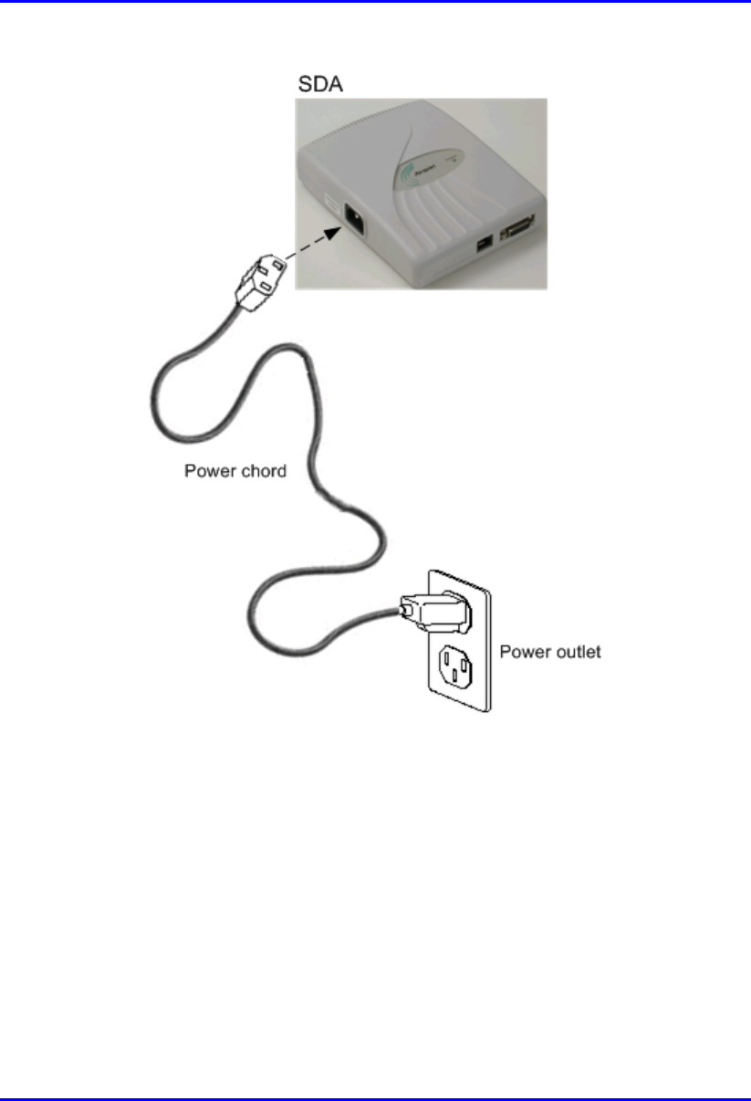
Hardware Installation Manual Installing the SDA
02030311-03 Airspan Networks Ltd. 9-21
Figure 9-16: SDA Power Cable Connections
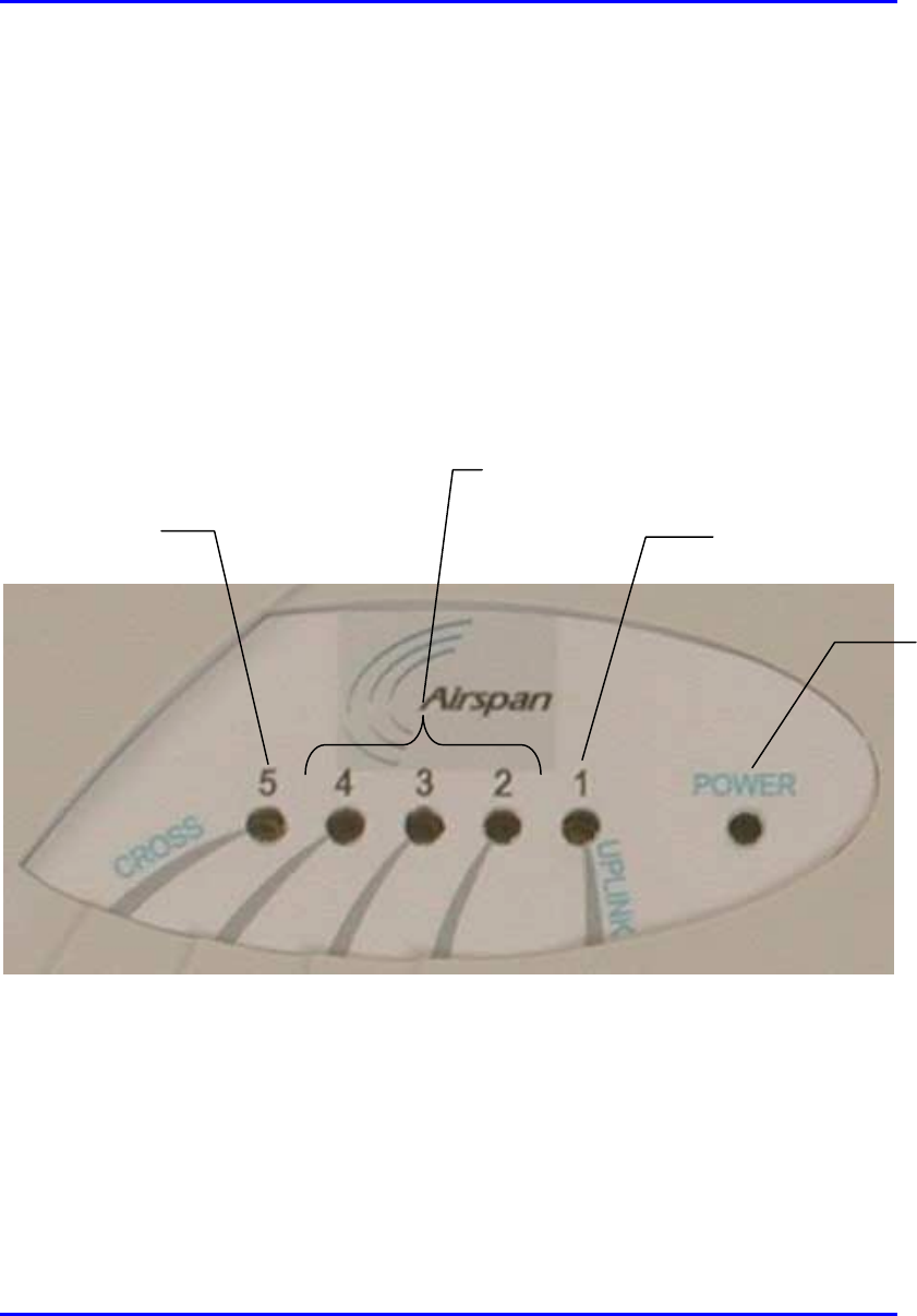
Installing the SDA Hardware Installation Manual
9-22 Airspan Networks Ltd. 02030311-03
9.7. LED Display
The SDA-4H and SDA-4S models provide LED indicators that indicate network
connection, traffic status, and power. These LEDs are located on the top panel of the
chassis.
9.7.1. SDA-4H
Figure 9-17 displays the location of the SDA-4H LED indicators.
Figure 9-17: SDA-4H LED indicators
UPLINK (1) LED
Ethernet LEDs (2, 3, and 4)
(
strai
g
ht-throu
g
h
)
CROSS (5) LED
POWER
LED

Hardware Installation Manual Installing the SDA
02030311-03 Airspan Networks Ltd. 9-23
Table 9-4 describes the SDA-4H LED indicators.
Table 9-4: Description of the SDA-4H LED Indicators
LED Color Status Meaning
On Physical link between SDA-4H and SPR
Blinking Traffic flow between SDA-4H and SPR
1 (UPLINK) Yellow
Off No link between SDA-4H and SPR
On Physical link between SDA-4H and Ethernet network
Blinking Traffic flow between SDA-4H and Ethernet network
2, 3, and 4 Yellow
Off No link between SDA-4H and Ethernet network
On Physical link between SDA-4H and crossover Ethernet port
connection
Blinking Traffic flow between SDA-4H and crossover Ethernet port
network
5 (CROSS) Yellow
Off No link between SDA-4H and crossover Ethernet port
connection
On Power received by the SDA-4H.
POWER Green
Off No power received by SDA-4H

Installing the SDA Hardware Installation Manual
9-24 Airspan Networks Ltd. 02030311-03
9.7.2. SDA-4S Models
Table 9-5 describes the SDA-4S model’s LED indicators.
Table 9-5: Description of the SDA-4S Model’s LED Indicators
LED Color Status Meaning
On Physical link (10BaseT) between SDA-4S and SPR
Blinking Traffic flow between SDA-4S and SPR
1 Orange
Off No link between SDA-4S and SPR
On 100BaseT physical link between SDA-4H and Ethernet
network
Blinking 100BaseT traffic flow between SDA-4H and Ethernet
network
Green
Off No traffic flow between SDA-4S and Ethernet network
On 10BaseT physical link between SDA-4H and Ethernet
network
Blinking 10BaseT traffic flow between SDA-4H and Ethernet
network
2, 3, 4, and 5
Orange
Off No traffic flow between SDA-4S and Ethernet network
On Power received by the SDA-4S model.
POWER Green
Off No power received by SDA-4S model.

02030311-03 Airspan Networks Ltd. 10-1
Installing and Configuring
Installing and Configuring Installing and Configuring
Installing and Configuring
the IDR
the IDRthe IDR
the IDR
This chapter describes the installation of the WipLL Indoor Data Radio (IDR) that
is installed at the subscriber's premises. The IDR unit is an optional WipLL unit that
replaces the SPR and SDA units, and combines the functionalities of the SPR and
SDA.
The IDR has a built-in antenna that provides an interface for transmission with the
base station, as well as an interface for 10Base-T Ethernet for the subscriber's
network. However, unlike the SDA, a separate power supply unit powers the IDR.
The IDR is available in two models: a model with an internal antenna, and a model
with a TNC connector for a third-party external antenna.
10
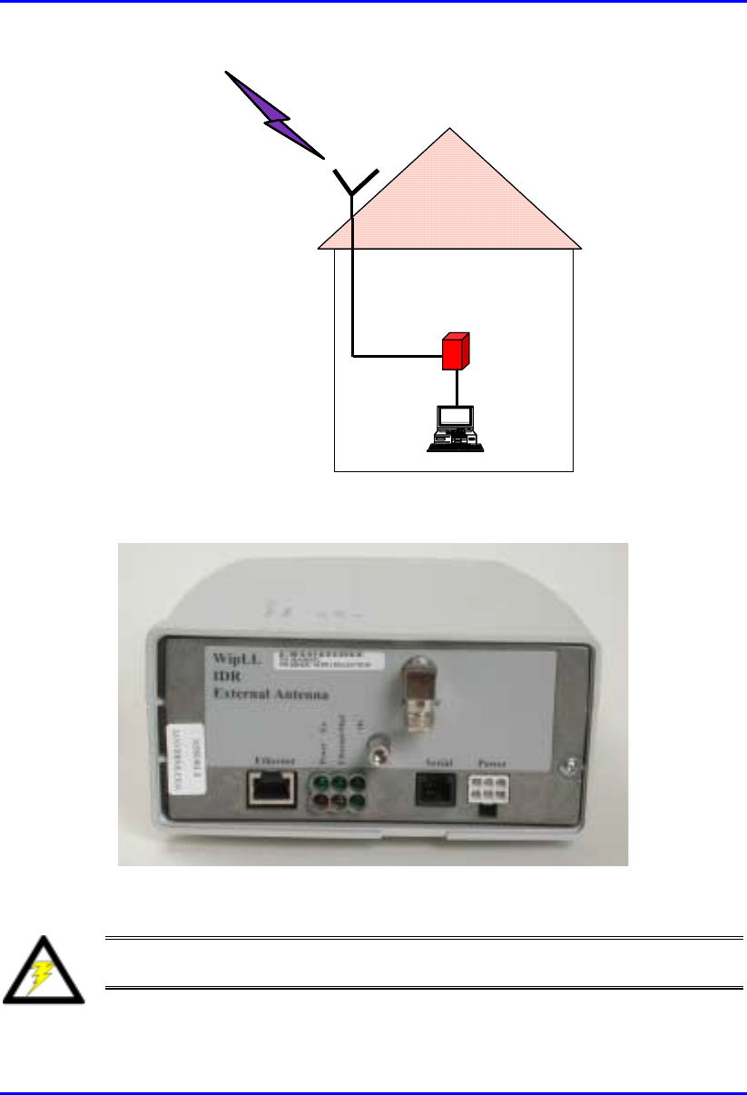
Installing and Configuring the IDR Hardware Installation Manual
10-2 Airspan Networks Ltd. 02030311-03
RF link
t
o BSR
Optional external
Optional externalOptional external
Optional external
antenna
antennaantenna
antenna
RF cable
IDR
PC
RF link
t
o BSR
Optional external
Optional externalOptional external
Optional external
antenna
antennaantenna
antenna
RF cable
IDR
PC
Figure 10-1: Typical IDR setup at subscriber's premises (showing optional antenna)
Figure 10-2: IDR with lower cover removed exposing ports
Warning: To avoid electrical or fire hazard, ensure that all connections to the
IDR are performed prior to connecting the power supply.

Hardware Installation Manual Installing and Configuring the IDR
02030311-03 Airspan Networks Ltd. 10-3
10.1. Mounting the IDR
The IDR may be mounted in the following ways:
! Desk
! Pole
! Wall
Note: Before mounting or attaching any brackets to the IDR ensure that all
cables are securely attached and that the unit functions correctly in the
proposed location.
10.1.1. Desk Mounting
The IDR may be mounted on a desk—horizontally or vertically—to obtain optimal
signal strength from a corresponding BSR.
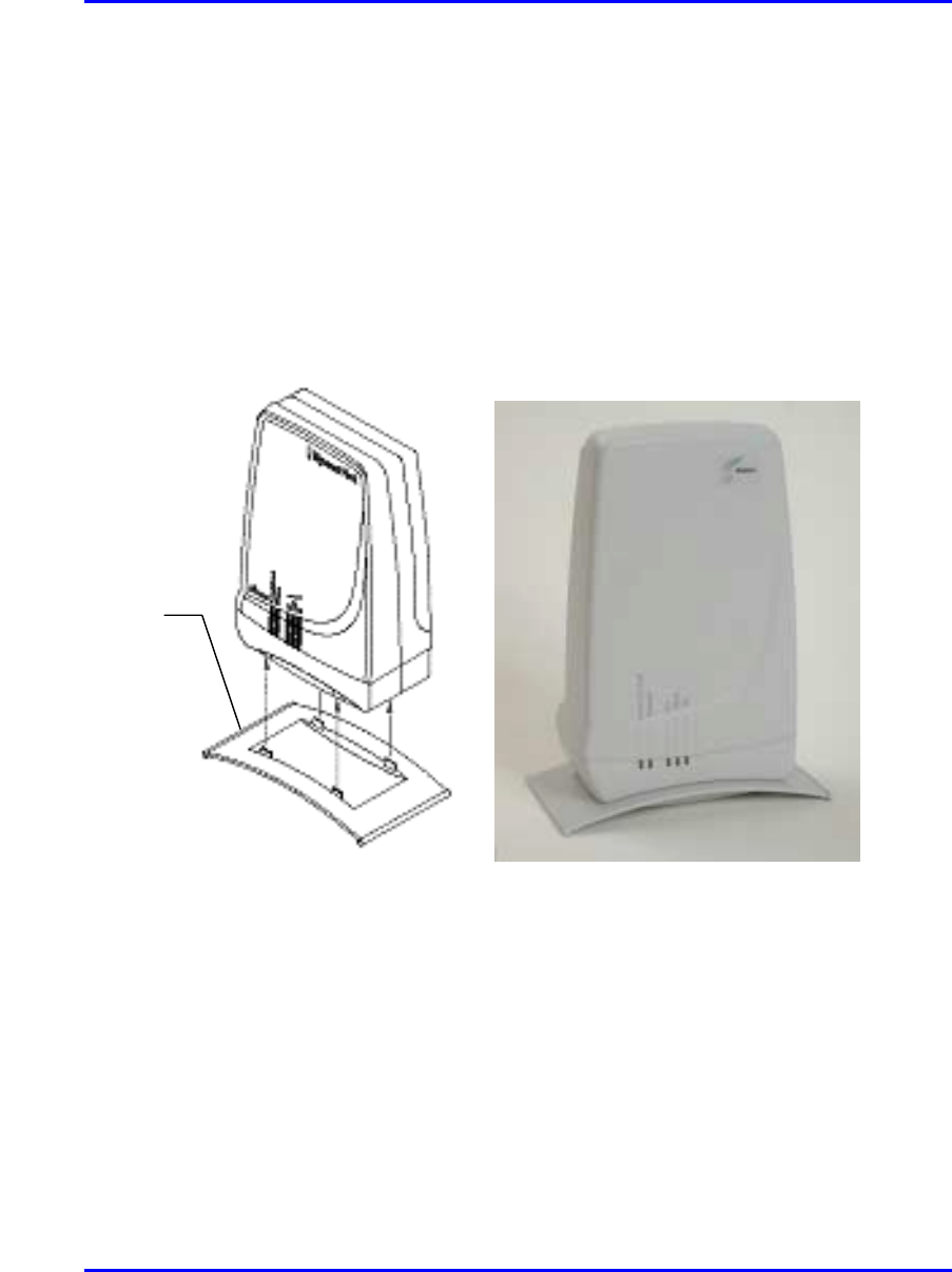
Installing and Configuring the IDR Hardware Installation Manual
10-4 Airspan Networks Ltd. 02030311-03
10.1.1.1. Vertical-Desk Mounting
A base plate is provided to mount the unit vertically on the desk, i.e., in standing
position. The base plate is designed to fit in one position only.
To desk mount the IDR in a vertical position:
! Insert the IDR into the base and press firmly until the tabs click into place. See
Figure 10-3.
Figure 10-3: IDR vertical desk mounting
Desk-
mounting
p
late
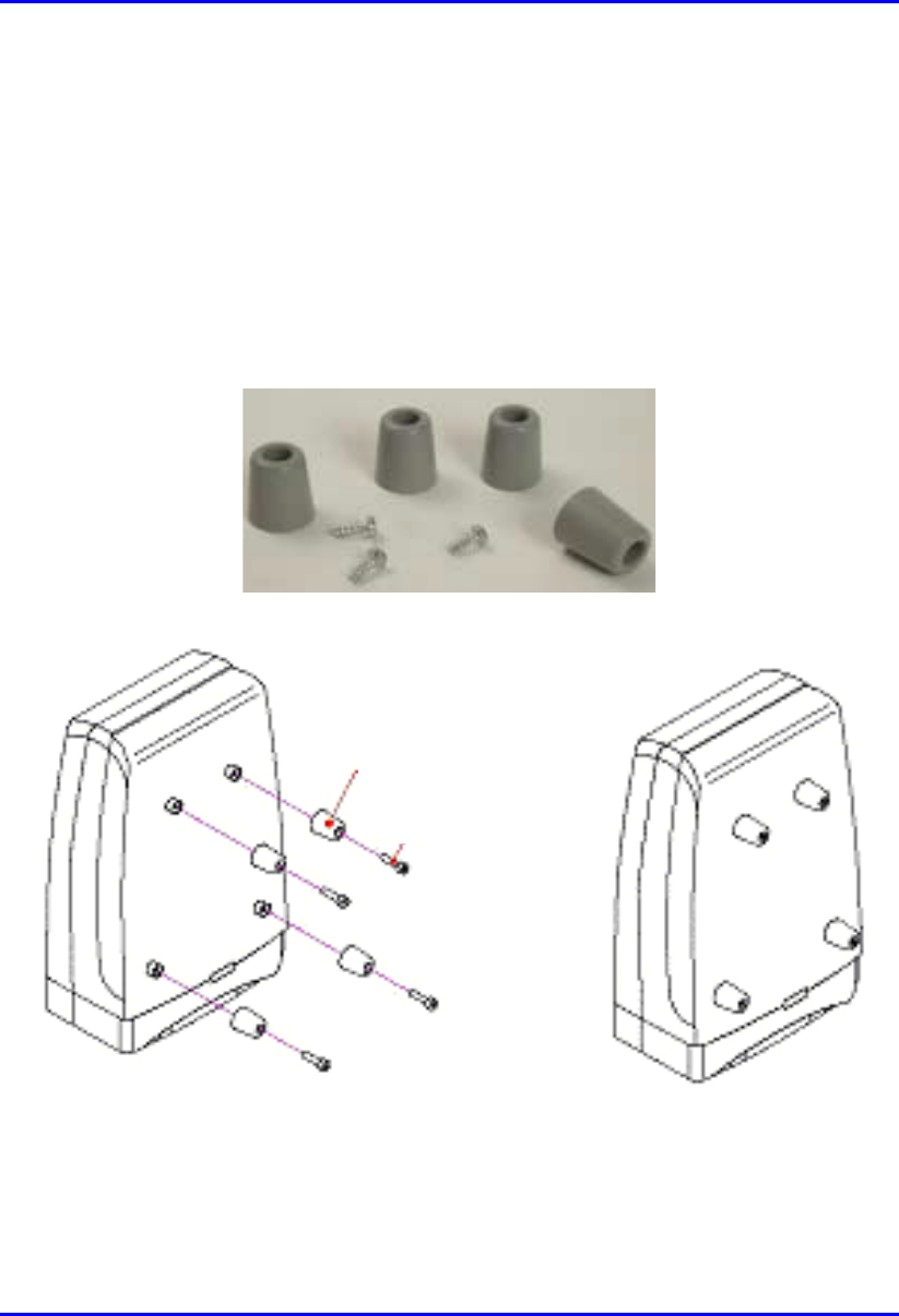
Hardware Installation Manual Installing and Configuring the IDR
02030311-03 Airspan Networks Ltd. 10-5
10.1.1.2. Horizontal-Desk Mounting
To position the IDR horizontally on the desk, four rubber pads, supplied with the
unit, must be fitted to avoid damage to mounting surfaces.
mTo desk mount the IDR in a horizontal position:
! Secure the rubber pads to the posts provided on the rear of the IDR using four
self-tapping screws. See Figure 10-4.
Figure 10-4: IDR horizontal desk mounting using supplied rubber pads and tapping
screws
Rubber foot
Screw
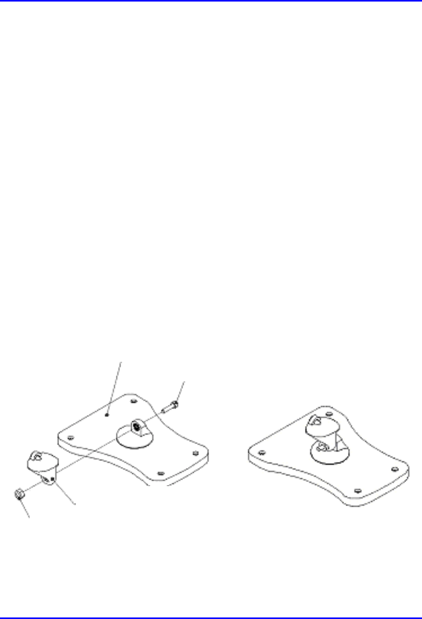
Installing and Configuring the IDR Hardware Installation Manual
10-6 Airspan Networks Ltd. 02030311-03
10.1.2. Wall and Pole Mounting
The IDR may be mounted to a wall or to a 5 cm-diameter pole. Wall and pole
mounting both use the same mounting brackets and wall hanger plate.
10.1.2.1. Assembling the Bracket and Hanger Plate
The wall hanger plate secures the IDR to a wall or pole. The wall bracket and hanger
plate allows positioning the IDR in the correct orientation. Holes are provided in the
wall hanger plate for both pole and wall mounting options
To assemble the bracket and hanger plate:
1. Insert a 4 mm hex nut into the slot on the tilt arm component
2. Holding the nut in place, attach the tilt arm to the mounting bracket using a 4
mm socket head bolt. Hand tighten the bolt only. See Figure 10-5.
3. Affix the complete mounting assembly to the rear of the IDR using the 4-off
self-tapping screws supplied with the kit.
Figure 10-5: Mounting bracket assembly
Mounting Bracket
Screw
Tilt Arm
N
ut
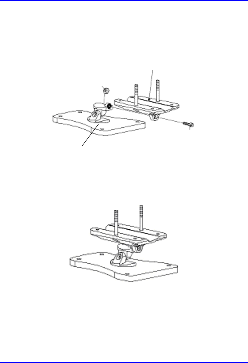
Hardware Installation Manual Installing and Configuring the IDR
02030311-03 Airspan Networks Ltd. 10-7
4. Attach the wall bracket assembly to wall hanger using an M4 socket-head bolt
and nut as shown in Figure 10-6. The bolt is only to be hand tightened at this
stage.
Wall Hanger
M-4 nut
Screw
Mounting bracket
assembly
Figure 10-6: Wall hanger fixing method
Figure 10-7: Wall hanger & mounting bracket assembly
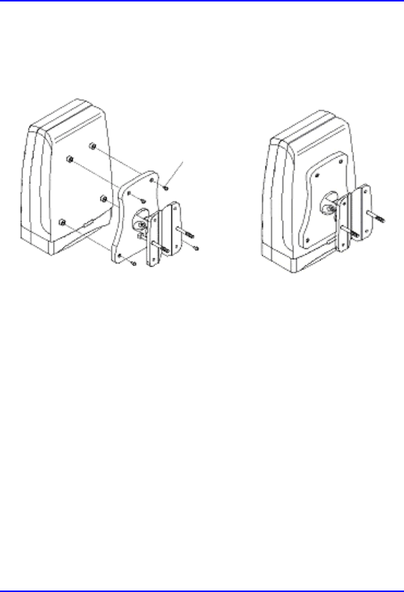
Installing and Configuring the IDR Hardware Installation Manual
10-8 Airspan Networks Ltd. 02030311-03
5. Once assembled, the IDR mounting bracket assembly may be secured to the rear
of the IDR using the 4-off self-tapping screws supplied in the unit fixing kit. See
Figure 10-8.
Figure 10-8: Mounting bracket assembly secured to IDR
10.1.2.2. IDR Pole Mounting
Prior to mounting the IDR to a pole the wall mounting bracket assembly must be
fitted as described in the previous section.
To pole mount the IDR:
1. Offer up the IDR assembly to the pole as shown in Figure 10-9.
2. Insert 2-off M10 bolts through the holes in the wall hanger.
3. Slide the clamp-holder into position and secure using washers, spring-washers
and nuts as illustrated in Figure 10-10. Finger-tighten the fasteners.
4. Slide the IDR to the required location on the pole and fully tighten the fasteners.
Self -
tapping
Screws
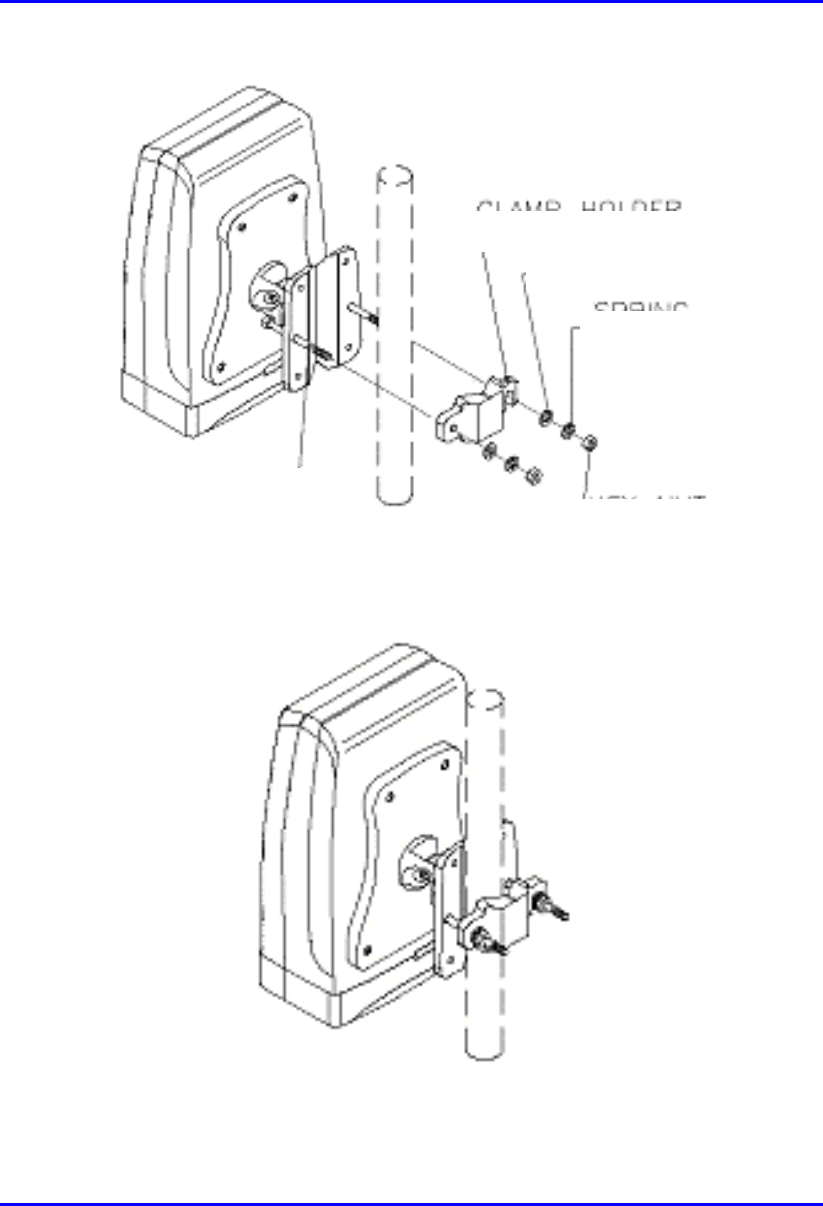
Hardware Installation Manual Installing and Configuring the IDR
02030311-03 Airspan Networks Ltd. 10-9
Figure 10-9: IDR pole mounting components
Figure 10-10: IDR secured to a pole
Clam
p
holde
r
Washe
r
Spring
Washe
r
Hex Nut
Bol
t

Installing and Configuring the IDR Hardware Installation Manual
10-10 Airspan Networks Ltd. 02030311-03
To set the correct IDR inclination:
1. Loosen the 2-off M4 socket head screws on the mounting bracket tilt-arm
2. Position the IDR at the desired angle.
3. Re-tighten the 2 off socket screws on the tilt arm.
10.1.2.3. IDR Wall Mounting
Warning: Prior to drilling holes in a wall ensure that there are no hidden
services such as electricity cables or water pipes.
A
stop must be used on the power drill to ensure that bored holes do not
exceed 35 mm.
To mount the IDR on a wall:
1. Loosen the 2-off M4 socket head screws on the mounting bracket tilt-arm and
remove the wall hanger.
2. Offer up the wall hanger to the wall and scribe through the mounting hole
locations.
3. Drill holes to suit the type of wall fixing.
4. If required insert anchor plugs suited to the wall material.
5. Affix the wall hanger using 4-off screws suited to the anchor plugs and wall
material.
6. Re-attach the IDR mounting bracket to the wall hanger. Finger tighten the
screws.
7. Position the IDR at the desired inclination.
8. Re-tighten the screws to lock the IDR in position.

Hardware Installation Manual Installing and Configuring the IDR
02030311-03 Airspan Networks Ltd. 10-11
10.1.3. Connecting a Third-Party External Antenna
The IDR provides a TNC-type connector for connecting the IDR to a third-party
antenna. This antenna can be placed on the subscriber’s window sill to provide
better RF signal reception.
Note: Airspan supplies unterminated cables for N-type connectors. Therefore,
refer to the cable crimping procedures for N-type connectors detailed in
Appendix tbd, “Cable Crimping".
Connector: TNC-type
10.1.4. Connecting to an Ethernet Network
The IDR provides one Ethernet interface for the subscriber’s Ethernet network. This
port is located on the front panel, and labeled Ethernet.
Connector: 8-Pin RJ-45
Cable: CAT-5e
Connector pinouts:
Pin Function
1 RX+
2 RX-
3 TX+
4
N
ot Connected
5
N
ot Connected
6 TX-
7
N
ot connected
8
N
ot connected
Installing and Configuring the IDR Hardware Installation Manual
10-12 Airspan Networks Ltd. 02030311-03
10.1.4.1. Ethernet LED Indicator
The IDR provides one LED that indicates an Ethernet connection. This LED is
labeled Ethernet and is located on the IDR’s top panel.
LED Color Status Indicates
On Physical link between IDR and
Ethernet network
Off No physical link between IDR and
Ethernet network
Ethernet Yellow
Blink Data is flowing through the Ethernet
port
10.2. Positioning IDR for Optimum RF
Reception
Once mounted to a wall, pole, or desk the IDR unit may be positioned to ensure the
best RF signal communication with the BSR. The RF signal strength is indicated by
three LEDs on the IDR chassis. The following table describes the RF signaling
strength indicator LEDs.
LED Color Status Indicates
LO Green Lit Low strength signal
MED Green Lit Medium strength signal
HI Green Lit High strength signal
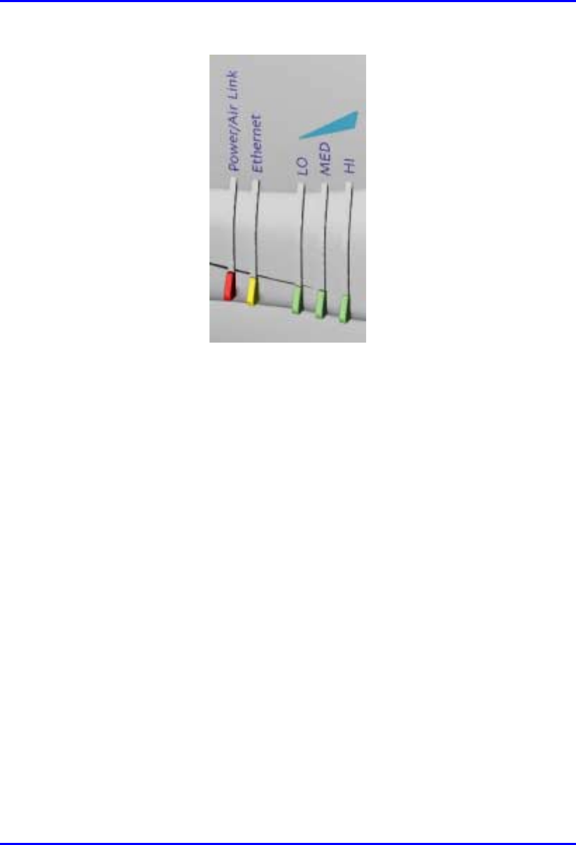
Hardware Installation Manual Installing and Configuring the IDR
02030311-03 Airspan Networks Ltd. 10-13
Figure 10-11: IDR LED indicators
To position the IDR for optimum RF signal:
! Position the IDR until all three RF signaling strength indicator LEDs are lit.
Refer to Section 10.1.2, “Wall and Pole Mounting” page 10-6 for details on
adjusting IDR wall and pole mounting position.
For desk-top mounting, the IDR can be simply relocated to obtain the strongest
signal.
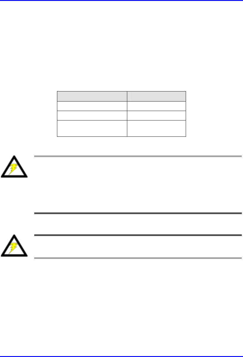
Installing and Configuring the IDR Hardware Installation Manual
10-14 Airspan Networks Ltd. 02030311-03
10.3. Connecting Power Supply
The IDR is powered by an external power supply (Triple Output External Adapter).
The IDR connects to the power supply via the power port located on the IDR’s front
panel.
The following table lists the external power supply specifications:
Power parameter Units
Voltages 110-240 VAC
Frequency 50 to 60Hz
Maximum power
consumption Less than 15W
Warning: Ensure that plugs fitted to mains power leads for subscriber
premises equipment are compatible with AC mains sockets. Do not replace
plugs on power leads to suit local requirements without first verifying earthing
practice for the country and equipment in question.
Careful consideration must be given to issues including local wiring
requirements, cable color-coding, and safety earthing and circuit protection
requirements.
Warning: To avoid electrical or fire hazard, ensure that the data connections
to the IDR are made prior to connecting the power supply.
The AC mains must be capable of supplying at least 230 VAC
Prior to connecting to the power outlet, the following pre-connection inspection
should be performed on power sockets:
! Power socket shall be visually inspected to ensure that no other equipment is
connected to the power outlet.
! There is no physical sign of damage to the power outlet.

Hardware Installation Manual Installing and Configuring the IDR
02030311-03 Airspan Networks Ltd. 10-15
! There should not be any visible sign of water or dampness on or around the
power outlet.
! The plug and socket assemblies are to be firmly secured.
! The power outlet shall be checked using a proprietary plug tester such as a
‘Martindale Ze’ type. Checks are required to verify the earth loop impedance
value and the presence of phase, neutral and earth connections.
Connector: 6-Pin power connector
Cable: 3-core 0.7mm² type
Connector pinouts:
Pin Function
1 +6.5V
2 +5V
3 3.3V
4 GND
5 Not connected
6 Not connected
To connect the power:
1. Connect the IDR’s 6-Pin power port to the supplied power adapter.
2. Connect the power chord to the adapter and then connect the other end to the
wall socket.

Installing and Configuring the IDR Hardware Installation Manual
10-16 Airspan Networks Ltd. 02030311-03
10.3.1. Power LEDs
The IDA provides a power LED indicator, labeled Power, which indicates whether a
power supply exists. The Power LED is located on the front panel of the IDR
chassis.
LED Color Status Meaning
On The SDA receives power
supply
Power Red
Off No power received
10.4. Configuring the IDR
To perform IDR initial configuration, you need to connect the IDR’s RJ-11 port to
the serial port of a PC running the WipLL network management application (i.e.,
WipConfig).
10.4.1. Connecting to a PC
The IDR provides a serial connection to a PC. The IDR’s RJ-11 port labeled Serial,
located on the front panel, connects to the serial port of a PC via a cable with an RJ-
11 connector on the one end, and a 9-Pin D-type connector on the other (i.e., a direct
serial cable connection-DCC).
! Connector:
! 6-Pin RJ-11 male to IDR
! 9-Pin D-type male to PC adapter
! Cable:
! Straight-through cable with 6-Pin RJ-11 male on one end and 9-Pin D-type
female on the other (Connects between IDR and crossed-over cable)
! Cross-over cable with 9-Pin D-type male on one end and 9-Pin D-type
female on the other (connects straight-through cable to PC)

Hardware Installation Manual Installing and Configuring the IDR
02030311-03 Airspan Networks Ltd. 10-17
! Connector pinouts:
Straight-through cable Crossover cable
6-Pin RJ-11 9-Pin D-type
female 9-Pin D-type
male 9-Pin D-type
male
Pin Function Pin Pin Pin
1 RX 2 4 3
2
N
ot connected - - -
3
N
ot connected - - -
4
N
ot connected - - -
5 GND 5 1 5
6 TX 3 3 2
- - -
- - -
- - -
To connect the IDR to the WipLL management station (PC):
1. Connect the 6-Pin RJ-11 connector to the IDR’s RJ-11 port (labeled Serial)
located on the IDR’s front panel (see Figure 10-12).
2. Connect the 9-Pin D-type female connector, at the other end of the straight-
through cable, to the 9-Pin D-type male connector of the cross-over cable (see
Figure 10-12).
3. Connect the 9-Pin D-type male connector, at the other end of the cross-over
cable, to the PC’s serial port (see Figure 10-12).
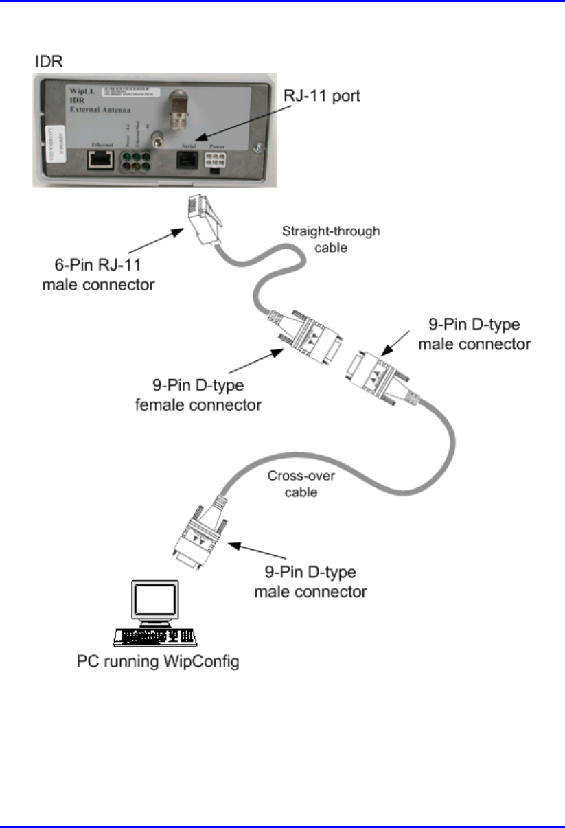
Installing and Configuring the IDR Hardware Installation Manual
10-18 Airspan Networks Ltd. 02030311-03
Figure 10-12: IDR-to-PC Serial Cable Connections
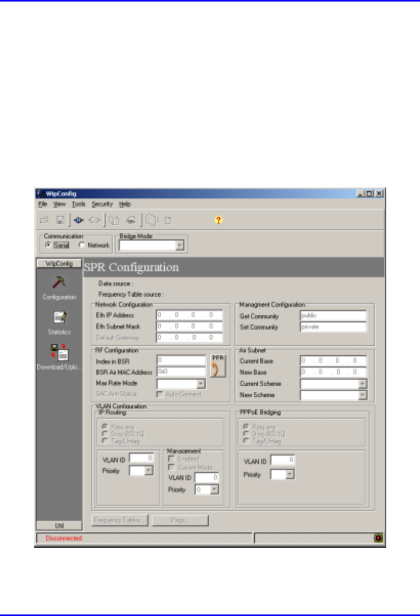
Hardware Installation Manual Installing and Configuring the IDR
02030311-03 Airspan Networks Ltd. 10-19
10.4.2. Configuring the SPR using WipConfig
When you connect the IDR to a PC, the configuration screen shown in Figure 10-13
is displayed. The parameters will be those read from the target device. (Data source:
TARGET).
To change parameters type the new values into the fields ensuring that the old data is
overwritten. An asterisk (*) will appear to indicate that the changes were not set and
saved. Use the Write button to set the changes to the target device then reset the
target to activate the changes.
Figure 10-13: IDR initial configuration using WipConfig

Installing and Configuring the IDR Hardware Installation Manual
10-20 Airspan Networks Ltd. 02030311-03
The following SPR Configuration screen descriptions give brief details of each
parameter:
! Eth IP Address - Displays the IP address of the target devices.
! Eth Subnet Mask - Displays the value of the subnet mask associated with the
Eth IP address.
! Get Community - This is the GET Community string. Default value = public.
! Set Community - This is the SET Community string. Default value = private.
! Index in BSR - The unique identity of this IDR within the BSR.Valid range = 2
- 127
! BSR Air MAC Address – The air identity of the IDR associated BSR.
! Max Rate Mode – The transmission speed setting
! Air Subnet Addresses and Schemes – The addresses and schemes of the air
subnets can be updated.
! Frequency Tables button – This is enabled only when using an IP (Network)
connection.

02030311-03 Airspan Networks Ltd. A-1
Glossary
GlossaryGlossary
Glossary
AC Alternating Current
A/F Across flats measurement
BNC Bayonet Neill Concelman (Connector type)
BSDU Base Station Distribution Unit
BSI Base Station Interface
BSPS Base Station Power System
BSR Base Station Radio
CEP Common Earth Point
DMM Digital Multimeter
DC Direct Current
DP Double Pole
DCC Direct Serial Cable Connection
GPS Global Positioning Satellite
HSP Hop Synchronisation Process
HSPP Hop Synchronisation Process Pulse
IDR Indoor Radio
IEC International Electrotechnical Commission
IEE institute of Electrical Engineers
IP Internet Protocol
LED Light Emitting Diode
mA Milliamperes
MCB Miniature Circuit Breaker
A

Glossary Hardware Installation Manual
A-2 Airspan Networks Ltd. 02030311-03
Mbps Mega Bits Per Second
Nm Newton-metres
NMS Network Management System
NOC Network Operations Centre
PSTN Public Switched Telephone Network
RJ Registered Jack (modular connector)
RFI Radio Frequency Interference
SDA Subscriber Data Adaptor
SME Small and Medium Enterprises
SOHO Small Office/Home Office
SPR Subscriber Premises Radio
UPS Un-interrupted Power Supply
UPVC Unplasticized Poly-Vinyl Chloride
WAN Wide Area Network
WipLL Wireless internet protocol -Local Loop

02030311-03 Airspan Networks Ltd. B-1
Cable Crimping
Cable CrimpingCable Crimping
Cable Crimping
This chapter describes the procedure for crimping cables for 15-Pin D-type and N-
type connectors that are used in BSR/SPR-to-BSDU/SDA and BSR-to-GPS
connections, respectively. The opposite ends of these cables are un-terminated,
thereby providing length flexibility for connecting these WipLL units.
Crimping procedures are described for the following cable-connector terminations:
! CAT-5e/15-Pin D-type cable/connector terminations for SPR-to-SDA
connections
! Multipair Overall Shielded (22 AWG)/N-type cable/connector terminations
for GPS antenna connections.
! GPS antenna connector
Warning: Correct crimping of network cables is crucial for ensuring service
integrity.
B.1. Crimping CAT-5e/15-Pin D-Type Cable
Connectors
This section describes the cable stripping and crimping of CAT-5e cables for 15-Pin
D-type connectors used for BSR/SPR-to-BSDU/SDA connections.
Airspan recommends the "ITT Canon DB15" (code number ‘DAW15P’) sub-
miniature type. This connector is an Insulation Displacement Connector (IDC)
which crimps and secures the cable at the connection point.
B
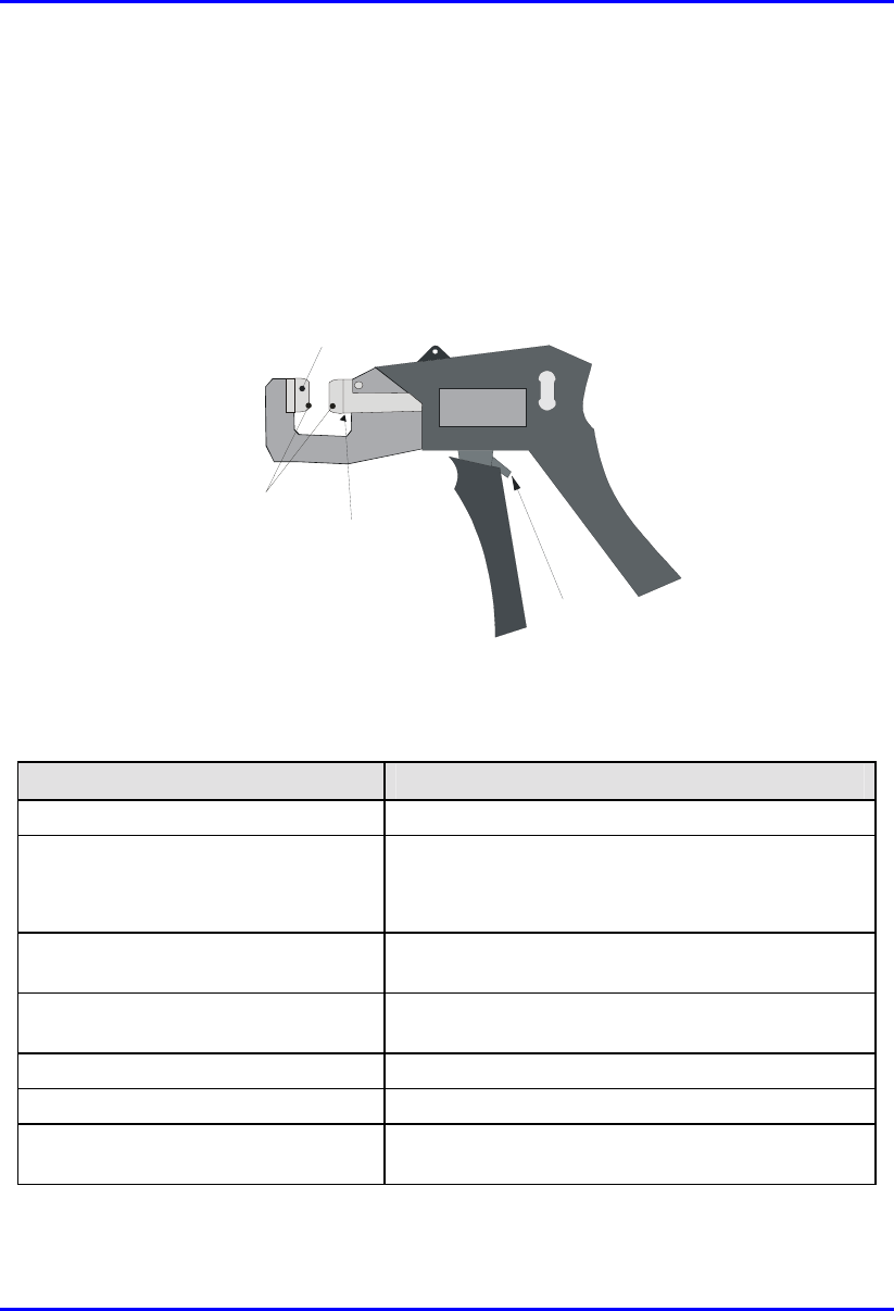
Cable Crimping Hardware Installation Manual
B-2 Airspan Networks Ltd. 02030311-03
Airspan recommends the following tools for stripping and crimping for 15-Pin D-
type connectors:
! Crimping tool—hand-crimper code DW115394-1. The crimper is a cyclic
crimper and will not release the cable until a full termination cycle has been
completed. The tool automatically indexes to the next pin on completion of the
terminating cycle.(See Figure B-1.)
Push in this direction to
release ratchet mechanism
Feed Slide
Connector Guide
Anti Backup
locator
Figure B-1: Hand-Crimping Tool for 15-Pin D-Type Connector
The major features of the crimper are described in the following table:
Tool feature Function
Terminating Head Guides and supports the connector.
Wire Inserter
• Cuts wire to be terminated.
• Forces conductors into 2 slotted beams of the
contact.
Anti-backup locator Prevents connector from moving out of position for
accurate termination.
Feed Slide Automatically advances the connector after each
termination.
Adjuster Provides wire insertion depth adjustment
Cam handle Activates the termination mechanism inside the head.
Ratchet Pawl Releases the cam handle before it is fully closed
should a problem occur during termination operation.

Hardware Installation Manual Cable Crimping
02030311-03 Airspan Networks Ltd. B-3
! Stripping tool—three-way stripping tool—1PAC10349AKM (see Figure B-2)
Adjustment Screw
Blade Adjustmen
t
Figure B-2: Stripping Tool 1PAC10349 AKM
Cable crimping is performed in two stages:
1. Stripping the cable
2. Crimping the cable
B.1.1. Stripping the Cable
Before crimping the cables, you need to strip 50 mm of the cable.
Before using the tool, ensure that the tool is correctly adjusted. Correct adjustment is
obtained when the blade cuts the outer insulation without damage to the insulation of
inner conductors.
To strip the cable:
1. Cut the cable to length using cable shears (Airspan code 1PAC10333AKJ).
2. Strip 50 mm of the sheathing using stripping tool.
3. Insert the cable in the jaws of the cutting tool by squeezing the handles together.
4. Rotate 10 times, release the tool, and remove the cable and insulation.

Cable Crimping Hardware Installation Manual
B-4 Airspan Networks Ltd. 02030311-03
5. Use a steel rule (1PAC10042AAV) to verify the stripped dimension.
6. Inspect the cut for evidence of damage, i.e. has the braid been cut? If so cut off
cable and reset tool.
B.1.2. Crimping the Cable
Once you have stripped 50 mm of the cable, you can begin crimping the cable to the
15-Pin D-type connector.
Note: For 15-Pin D-type connector pinouts, see the relevant chapter on the
specific WipLL equipment.
To crimp the cable:
1. Insert the 15-Pin D-type connector into the left slot of the crimper until the
desired connector pin position aligns with the slot.
2. Insert the wire into the left side of the crimper slot until the end enters the hole.
3. Adjust the desired length of the wire.
4. Centre the wire in the slot.
5. Squeeze the crimper handles until the wire inserter bottoms out.
6. Release the crimper handles—the inserter retracts and the connector advances to
the next pin position.
7. Repeat the above until all pin contacts of the row have been terminated.
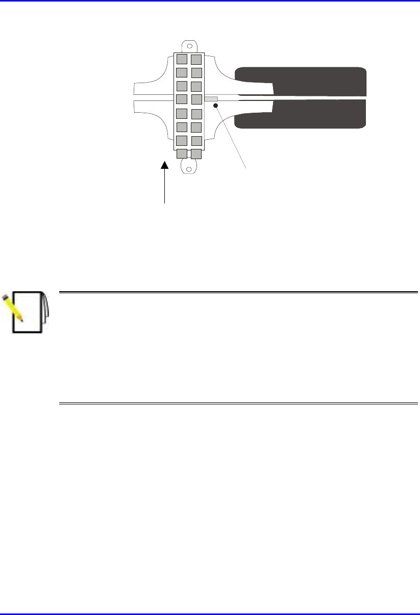
Hardware Installation Manual Cable Crimping
02030311-03 Airspan Networks Ltd. B-5
Connector advances in
this direction
Wire Slot
Figure B-3: Crimping tool
8. When finished, remove the connector from the right side of connector slot.
Note: The connector must be inserted into the crimper from the left hand side
only.
Should the connector jam in the terminating position, excessive force must not
be used: the spigot between the tool handles should be used to release the
ratchet mechanism.
The crimper handle will not allow release until a full termination cycle of the
connector has been completed.
B.1.3. Inspecting the Crimped Connector
Each crimped connector is to be tested that it has been correctly crimped:
! Ensure that the wire extends beyond the front pin contact slot by a minimum of
0.5 mm
! Ensure that the two legs of the insulation crimp barrel are closed to secure the
insulation of the wire
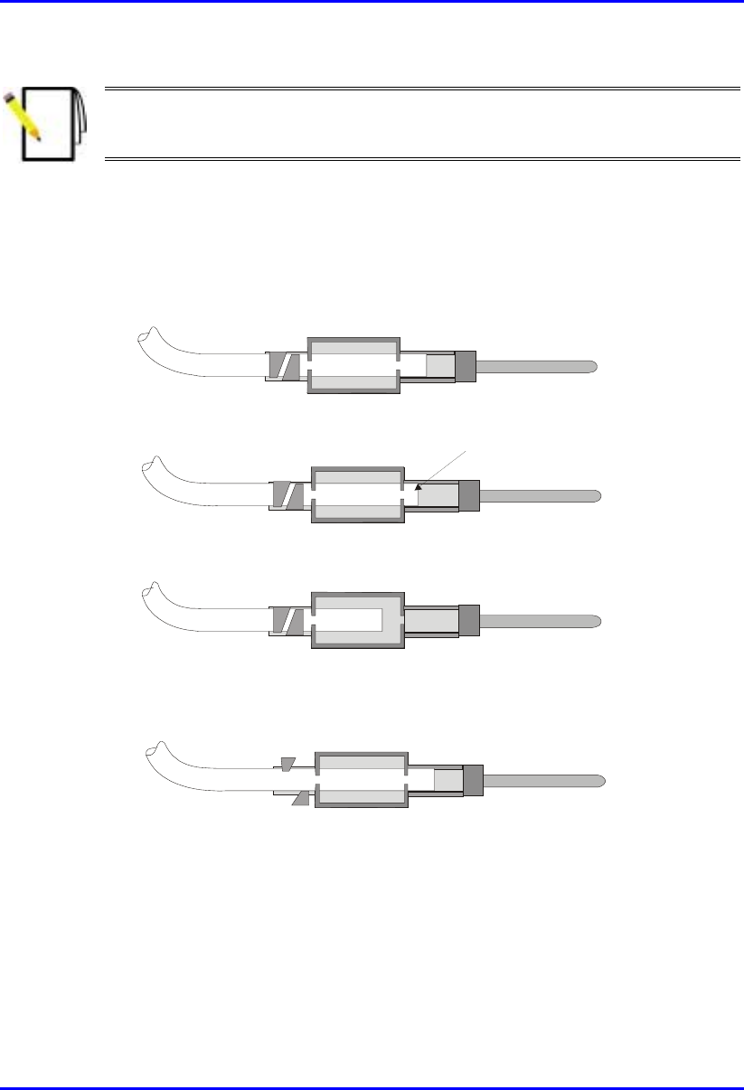
Cable Crimping Hardware Installation Manual
B-6 Airspan Networks Ltd. 02030311-03
Note: The purpose of the barrel is to prevent the wire from being lifted from
the contact. It is not necessary to have the barrel wrapped tightly around the
insulation.
! Ensure that the contact cavity has not been deformed
! Confirm integrity by holding the connector in one hand and pulling lightly on
the cable.
Figure B-4 shows points to be observed during quality inspection.
Correct Termination
Acceptable Termination
Wire was not fully inserted before termination
( or was slightly drawn back during termination)
Incorrect setting of tool
0.5mm Min
Figure B-4: Crimp Connector Inspection
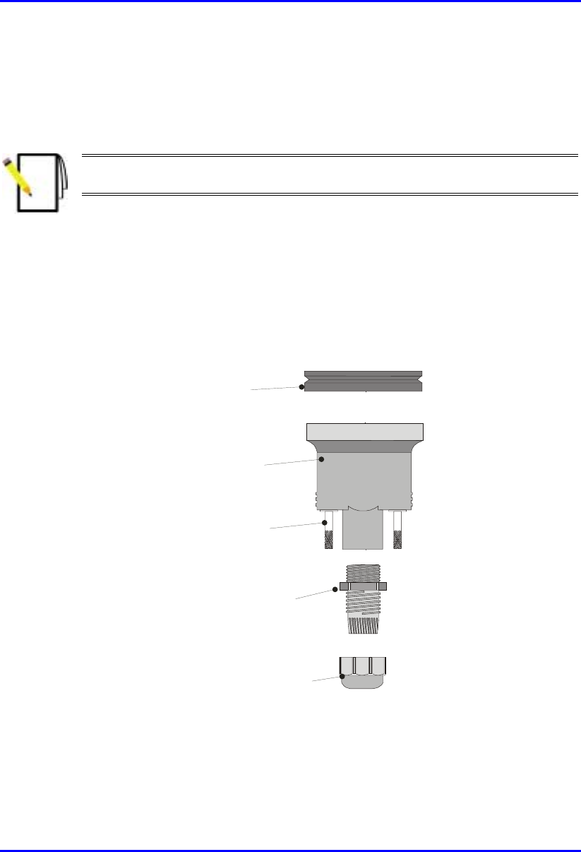
Hardware Installation Manual Cable Crimping
02030311-03 Airspan Networks Ltd. B-7
B.1.4. Housing the Connector
For outdoor cable installations, the connector is to be protected in a waterproof
housing assembly as shown in Figure B-5.
Note: The housing, cable seal, and clamping nut are to be slid onto the cable
prior to crimping the connector in place.
To assemble the connector in a waterproof housing:
1. Insert the connector into the waterproof housing ensuring that a "click" is heard.
2. Screw the cable seal into place ensuring that the cable outer sheath is inside the
connector body.
3. Secure the cable in place with the lock nut.
Cable Seal
Clamping Nut
Sealing Ring
Connector Housing
Securing Screws
Figure B-5: Waterproof Connector housing assembly
For indoor cabling applications it is not necessary to use a waterproof housing for
the connector.

Cable Crimping Hardware Installation Manual
B-8 Airspan Networks Ltd. 02030311-03
To assemble the un-housed connector:
1. Insert the connector terminal block into the connector body.
2. Secure the cable onto the connector body using the cable clamp. Ensure that the
cable outer sheath is within the connector body.
3. Snap the top section of the connector body into place.
4. Ensure that the connector is secure within the housing by applying a light pull on
the cable.
B.2. Crimping N-type Connectors
This section describes the cable stripping and crimping Multipair Overall Shielded
(22 AWG) cables for N-type connectors used for BSR/SPR connections to external
antennas.
Airspan recommends using the following tools for crimping of N-type connectors:
! Crimp tool: Erma 29020 with die set 29207.
! Stripping tool: Maxi Corex, fitted with the 9.0 to 11.5mm cable clamp (blue)
and the 9.5 to 3.2 blade cassette (green).
B.2.1. Stripping the Cable
To strip the cable:
1. The first cut should be set to cut through the outer sheath, braid and dielectric.
Scoring of the centre conductor should not occur.
2. The second cut should be set to cut through the outer sheath and the braid.
Important attention must be paid to the dielectric where it meets the braid. It is
preferable that no cutting of the dielectric takes place, however, because of the
construction of cables and tolerance build up there may be occasion where a
slight cutting of the dielectric is unavoidable. This must be kept to an absolute
minimum. This has been termed the compromise cut and is acceptable practice.

Hardware Installation Manual Cable Crimping
02030311-03 Airspan Networks Ltd. B-9
3. The final cut should be set to cut through the outer sheath only. Scoring of the
braid should not occur.
4. All sections of the stripped Ethernet cable should be easily removed if the blade
settings are correct. To adjust the blade settings use the allen key provided and
apply it to the grub screws at the back of the stripping tool. Clockwise will
increase blade depth, anti-clockwise will reduce blade depth.
5. Set stripping tool slide mechanism to 5.
6. Place the cable into the stripping tool with approximately 12 mm protruding
from the end of the tool.
7. Clamp the tool around the cable and lock in position.
8. Holding the cable in the left hand and stripping tool in the right hand (index
finger through finger hole) rotate tool in a clockwise direction for 10 turns.
9. Move slide mechanism to number 3.
10. Rotate tool in a clockwise direction for 10 turns.
11. Move slide mechanism to number 1.
12. Rotate tool in a clockwise direction for 10 turns.
13. Unlock the tool to remove cable then lock shut. Always keep the stripping tool
locked shut when not in use. Take care when handling the blade insert.
14. Twist off stripped cable sections.
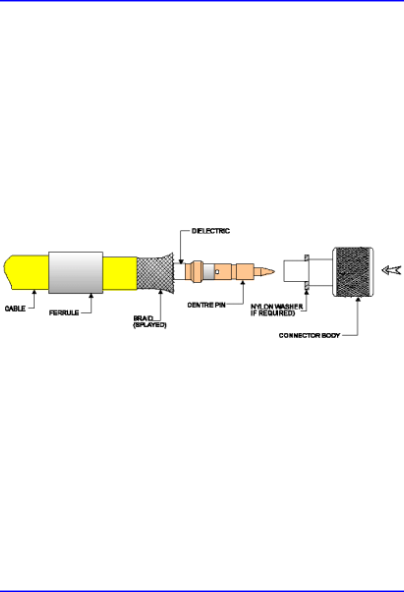
Cable Crimping Hardware Installation Manual
B-10 Airspan Networks Ltd. 02030311-03
B.2.2. Assembling the Connector
Once you have stripped the cable, you can house the cable:
To house the cable:
1. Fit an insulating boot if required, over the cable, cutting enough of the pointed
end to enable the cable to go through the resulting hole with a fairly tight grip.
Push ferrule over the stripped section of cable.
2. Rotate the centre conductor in relation to the cable to splay the braid and any foil
from the dielectric, which will allow the later correct fitting of the connector
body (over the dielectric). See Figure B-6.Take care not to damage the braid.
Figure B-6: Rotating conductor
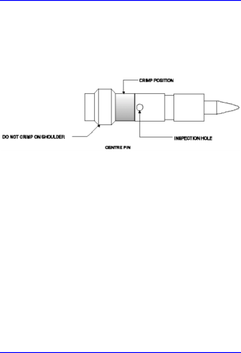
Hardware Installation Manual Cable Crimping
02030311-03 Airspan Networks Ltd. B-11
3. Trim the centre conductor back to 5.5 mm from the end of the dielectric. Use the
cable shears provided and not the side cutters.
4. Fit centre pin on to the centre conductor. The centre conductor should be seen
through the inspection hole (see Figure B-7). Ensure that the shoulder of the pin
is butted up to the cable’s dielectric.
Figure B-7: Fitting center pin onto center conductor
B.2.3. Crimping
To crimp the GPS connector:
1. Using an Erma tool and 29207 die, small aperture, crimp centre pin to centre
conductor. The crimp section should be just be below the inspection hole (see
Figure B-7). Do not crimp the shouldered section as it will cause flashing.
2. Fit the connector body over the centre pin and between the braid and dielectric
(see Figure B-6). Do not trap any of the braid between the dielectric and back
face of the connector body. If the connector is supplied with a nylon washer, fit
this to the rear of the connector before application to the cable.
3. Push the connector body firmly home. The centre pin should align with the end
of the internal diameter of the connector body.
4. Push the ferrule up to the end of the cable, covering the braid. There should be
no braid showing between the end of the ferrule and the connector body.
Rotating the ferrule may rectify this, if not trim the braid slightly to suit.
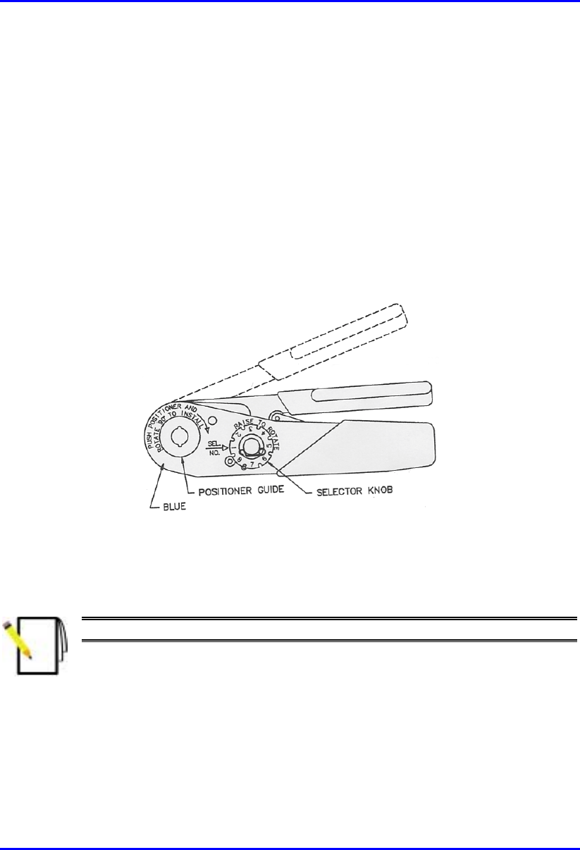
Cable Crimping Hardware Installation Manual
B-12 Airspan Networks Ltd. 02030311-03
5. Crimp the ferrule using the large aperture of the 29207 die. When offering up the
tool the die should be positioned so as it aligns with the braid and not the outer
sheath of the cable.
6. Connectors with nylon washers, the crimp is to be made with the dies held
firmly against the washers face.
B.3. Crimping GPS Cable Connectors
Airspan recommends the following tools for crimping for N-type connectors:
! Crimping tool—Daniels AFM8 (M22520/2-01).
Figure B-8: Crimping tool – Daniels AFM8
Once you have housed the stripped cable, you can now crimp the cable to an N-type
connector.
Note: The crimper cannot be opened without completing the cycle.
To crimp the cable:
1. Ensure that the crimper is in the open position.
2. Remove safety clip from positioner guide.

Hardware Installation Manual Cable Crimping
02030311-03 Airspan Networks Ltd. B-13
3. Select the Positioner for contact to be crimped.
4. Insert the Positioner into the positioner guide and turn it 90 degrees until bayonet
pins lock.
5. Raise and rotate the Selector knob until the number indicated on data plate for
cable size to be crimped is in line with Sel. No. arrow.
6. Insert the contact and prepared cable into the indenter opening from the side
opposite the Positioner.
7. Squeeze crimper handles together until the ratchet releases. The handle will
return to the open position.
8. Remove crimped contact and cable.

02030311-03 Airspan Networks Ltd. C-1
Technical Specifications
Technical SpecificationsTechnical Specifications
Technical Specifications
This appendix lists the technical specifications for the following WipLL units:
! WipLL Base Station equipment:
! Base Station Radio (BSR)
! Point-to-Point Radio (PPR)
! Base Station Distribution Unit (BSDU)
! Base Station Power Supply (BSPS)
! GPS antenna
! WipLL Customer premises equipment:
! Subscriber Premises Radio (SPR)
! Subscriber Data Adapter (SDA)
− SDA-1
− SDA-4H
− SDA-4S models
! Indoor Data Radio (IDR)
C

Technical Specifications Hardware Installation Manual
C-2 Airspan Networks Ltd. 02030311-03
C.1. Base Station WipLL Equipment
The following sub-sections list the specifications of the following WipLL Base
Station equipment:
! Base Station Radio (BSR)
! Point-to-Point Radio (PPR)
! Base Station Distribution Unit (BSDU)
! Base Station Power Supply (BSPS)
C.1.1. Base Station Radio (BSR)
Table C-1: BSR and MAC Specifications
Parameter Value Comment
Operating frequency range • 2.4 GHz
• 3.x GHz, MMDS, 2.8 GHz
• 5.8 GHz
• ISM band
• Licensed band
• Licensed band
*Other ranges available for
trial
Spectrum spreading method Frequency hopping Per ETSI EN301 253
Duplex method • Time Division Duplex
(TDD) - 2.4 GHz, 2.8 GHz,
3.x GHz, MMDS, and 5.8
GHz
• Frequency Division Duplex
(FDD) - 3.x GHz
Transmit bit rates Up to 4 Mbps BER and distance dependent
Channel spacing 1 MHz
Output power from the BSR Up to 27 dBm, configurable at
2.4 GHz Depending on local
regulations, maximum output
power can be configured at the
factory
Modulation method 8-level CPFSK

Hardware Installation Manual Technical Specifications
02030311-03 Airspan Networks Ltd. C-3
Parameter Value Comment
Channel access method PPMA / Adaptive TDMA
Protocol efficiency Up to 80% For large data packets
Number of SPR/IDR per BSR Up to 126
Table C-2: BSR EMC and Radio Standards Compliance
Parameter Value
Radio Standards Compliance • ETSI EN 300 328-1
• ETSI EN 301 253
• FCC part 15
• RSS139
• Telec
EMC • ETSI ETS 300 826
• ETSI EN 300 385
• ETSI EN 300 386-2
• ETSI ETS 300 132-2
• FCC part 15
Table C-3: BSR Agency Certification
Parameter Value
Emissions / Immunity EN 300 339 EN 300 386-2 ETS 300 328
Safety EN / IEC 60950
Environmental ETS 300 019-2-x
Table C-4: BSR Network Specifications
Parameter Value Comment
Filtering Rate 10,500 frames/sec At 64 byte packets
Forwarding Rate 1,300 frames/sec At 64 byte packets
Routing table length 200 networks, including
subnets

Technical Specifications Hardware Installation Manual
C-4 Airspan Networks Ltd. 02030311-03
Table C-5: BSR Power Requirements
Parameter Value Comment
Voltage
• Minimum:
• Maximum:
48 VDC nominal
• 30 VDC
• 55 VDC
Voltage is received from the
BSDU
Maximum Amperes: 500 mA
Table C-6: BSR Environmental Conditions
Parameter Value Comment
Operating temperature of
outdoor units (BSR and SPR) -30ºC to +60ºC Optional range of -40ºC to
+70ºC
Storage temperature -40ºC to +80ºC
Table C-7: BSR Network Interface
Parameter Value Comment
Ethernet Network UTP EIA/TIA Category 5
Standards Compliance ANSI/IEEE 802.3 and
ISO/IEC 8802-3 10Base-T
compliant
Serial Port RS-232
Table C-8: BSR Physical Dimensions
Parameter Value Comment
Height 400 mm
Width 317 mm
Depth 65.5 mm
Weight 4.7 kg
Excluding mounting kit

Hardware Installation Manual Technical Specifications
02030311-03 Airspan Networks Ltd. C-5
C.1.2. Point-to-Point Radio (PPR)
Table C-9: PPR Radio Specifications
Parameter Value
Operating frequency bands • 2,400 to 2,500 MHz
• 3,400 to 3,800 MHz
• 5,725 to 5,875 MHz
Duplex method • Time Division Duplex (TDD) for all bands
• Frequency Division Duplex (FDD) for 3.4 to 3.8 GHz
Radio Technology FH-CDMA
Multiple Access Method PPMA
Output power 27 dBm
Antenna type (built-in)
• PPR
• SPR
• 18 / 16 / 15 dBi
• 18 / 16 / 15 dBi
Sub-Channel Spacing 1 MHz
Modulation Multilevel (2, 4, or 8) CPFSK
Receiver Sensitivity (BER 1E-
6 at 2/4/8 FSK) -90/ -83/ -75 dBm
Throughput Up to 4 Mbps per PPR-SPR link
Radio Standards Compliance • ETSI EN 300 328-1
• ETSI EN 301 253
• FCC part 15
• RSS139
• Telec
EMC • ETSI ETS 300 826
• ETSI EN 300 385
• ETSI EN 300 386-2
• ETSI ETS 300 132-2
• FCC part 15

Technical Specifications Hardware Installation Manual
C-6 Airspan Networks Ltd. 02030311-03
C.1.3. Base Station Distribution Unit (BSDU)
Table C-10: BSDU Network Specifications
Parameter Value
Filtering Rate 105,000 Frames / sec
Forwarding Rate 62,500 Frames / sec
Table C-11: BSDU Power Requirements
Parameter Value
Voltage 48VDC nominal
Power consumption Maximum 300W (including the feeding of 6 × BSRs)
Table C-12: BSDU Environmental Conditions
Parameter Value
Operating Temperature 0ºC to +50ºC
Storage Temperature -40ºC to +80ºC
Table C-13: BSDU Network Interface
Parameter Value Comment
Ethernet Network 100/10Base-T: UTP EIA/TIA Category 5
Standards Compliance ANSI/IEEE 802.3, ISO/IEC 8802-3
10/100 Base-T compliant
Serial Port RS-232
Table C-14: BSDU Physical Dimensions
Parameter Value
Height 4.32 cm
Width 48.26 cm
Depth 22.86 cm
Weight 2.9 kg

Hardware Installation Manual Technical Specifications
02030311-03 Airspan Networks Ltd. C-7
C.1.4. Base Station Power Supply (BSPS)
Table C-15: BSPS Rectifier Specifications
Parameter Value
Voltage 90VAC to 270VAC
Current (nominal) 3.2A @ 230V / 4.3A @ 115V
Frequency 47Hz to 63Hz
Input
Power factor (nominal line/load) Greater or equal to 0.993
Voltage (default) 53.5VDC
Regulation (line & load) ±0.4%
Adjustable range 47 to 58 VDC
Current 12A @ 54V
Ripple & noise 50mVp-p
Efficiency (nominal load) 85% @ 230V / 82% @ 115V
Overload current <12A
Over-voltage protection 60 VDC
Over-temperature protection (measured
on case, upper panel corner)
• 80±5°C rectifier stops
• 72±5°C rectifier recovers
Walk-in time < 0.5 sec
Output
Hold-up time 40 ms
Withstand voltage (1 min) • 4230VDC INPUT/OUTPUT
• 2120VDC INPUT/GND
• 1700VDC OUTPUT/GND
Working temperature -10 to 45°C
Storage temperature -50 to 80°C
Dimensions (mm) 235 x 150 x 50 (L x W x H)
Weight 1100g
EMC Refer to system specifications
General
Safety According to: IEC950

Technical Specifications Hardware Installation Manual
C-8 Airspan Networks Ltd. 02030311-03
Table C-16: BSPS DC Distribution Specifications
Parameter Value
Voltage 90VAC to 270VAC
Current (at full load)
N =Number of rectifier modules
• N*3.2A @ 230V
• N*4.3A @ 115V
Frequency 47 Hz to 63 Hz
Power factor (at full load) Greater or equal to 0.993
Input
Voltage (programmable) 42 to 60VDC ± 0.5VDC
Default float and boost voltage 54 and 57VDC respectively
Regulation (line, load, sharing) ±1%
Current N*12A (48A max.)
Psophometric noise -52 dBm (over 600 &)
Ripple & noise 50mVp-p
Efficiency (nominal load) 85% @ 230V / 82% @ 115V
Overload current < N*12A
Over-voltage protection 60VDC
Walk-in time < 1 sec
Hold-up time 40 ms
Output current indication 10 LED’s bar-graph
Active current sharing ±10% accuracy at full load
Output
Withstand voltage (1 min) 2120VDC INPUT/GND
Working temperature -10 ¸ 45°C
Storage temperature -50 ¸ 80°C
Dimensions (19” X 3U) Depth is 320mm W/O terminals,
360mm with terminals
Weight 13 kg (main unit + 3 rectifiers)
General
RS232 Communication 9600 bps, no-parity, 1 stop-bit

Hardware Installation Manual Technical Specifications
02030311-03 Airspan Networks Ltd. C-9
Parameter Value
EMC According to:
• EN300-386-2 SUB 7.2.3
• EN55022 class B
• IEC1000-4-2
• IEC1000-4-3
• IEC1000-4-4
• IEC1000-4-5
• IEC1000-4-6
• IEC1000-4-11
• IEC1000-3-2
• IEC1000-3-3
Safety According to: IEC950
Maximum current withstand 2x70A
LVLD
(optional) Trip voltage level Disconnect default: 43± 0.5 VDC, user
programmable Re-connect: with AC
recovery

Technical Specifications Hardware Installation Manual
C-10 Airspan Networks Ltd. 02030311-03
C.1.5. GPS antenna
Table C-17: SPR Power Requirements
Parameter Value Comment
Voltage Input 36 VDC Supplied by WipLL’s BSDU
Consumption 1.8W
Table C-18: Environmental Considerations
Parameter Value Comment
Operating temperature
-30ºC to +75ºC
Table C-19: GPS General
Parameter Value Comment
Input DGPS (Differential GPS)
Output 1 pulse per second
Standards Compliance MIL-STD 810E
Interface standard RS-422
Table C-20: GPS Dimensions
Parameter Value Comment
Diameter 115 mm
Height 90 mm

Hardware Installation Manual Technical Specifications
02030311-03 Airspan Networks Ltd. C-11
C.2. Customer Premises WipLL Equipment
The following sub-sections list the specifications of the following WipLL CPE
equipment:
! Subscriber Premises Radio (SPR)
! Subscriber Data Adapter (SDA)
! Indoor Data Radio (IDR)
C.2.1. Subscriber Premises Radio (SPR)
Table C-21: SPR and MAC Specifications
Parameter Value Comment
Operating frequency • 2.4 GHz
• 3.x GHz, 2.8 GHz, MMDS
• 5.8 GHz
• ISM band
• Licensed band
• Unlicensed band
Spectrum spreading method Frequency hopping Per ETSI EN 301 253
Duplexing Method • Time Division Duplex (TDD)
2.4 GHz, 2.8 GHz, MMDS, 3.x
GHz, and 5.8 GHz
• Frequency Division Duplex
(FDD) 3.x GHz
Transmit Bit Rates Up to 4 Mbps BER and distance dependent
Channel spacing 1 MHz
Output power from the radio Up to 27 dBm, configurable at 2.4
GHz Depending on local
regulations. Maximum
power output can be set at
the factory.
Modulation method 8 level CPFSK
Channel access method PPMA / Adaptive TDMA
Protocol efficiency Up to 80% For large data packets

Technical Specifications Hardware Installation Manual
C-12 Airspan Networks Ltd. 02030311-03
Table C-22: SPR EMC and Radio Standards Compliance
Parameter Value
Radio Standards Compliance • ETSI EN 300 328-1
• ETSI EN 301 253
• FCC part 15
• RSS139
• Telec
EMC • ETSI ETS 300 826
• ETSI EN 300 385
• ETSI EN 300 386-2
• ETSI ETS 300 132-2
• FCC part 15
Table C-23: SPR Agency Certification
Parameter Value Comment
Emissions / Immunity EN 300 339, EN 300 386-2,
ETS 300 328
Safety EN/IEC 60950
Environmental ETS 300 019-2-x
Table C-24: SPR Network Specifications
Parameter Value Comment
Filtering rate 10,500 frames / sec At 64 bytes
Forwarding rate 1,300 frames / sec At 64 bytes
Routing table length 16
Table C-25: SPR Power Requirements
Parameter Value Comment
• Voltage
• Minimum
• Maximum
• 48 VDC nominal
• 30 VDC
• 55 VDC
Power supplied from the SDA
Consumption Maximum 500 mA
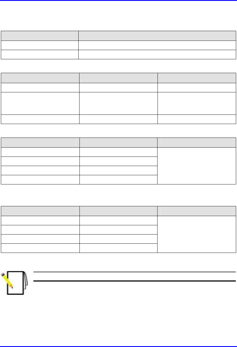
Hardware Installation Manual Technical Specifications
02030311-03 Airspan Networks Ltd. C-13
Table C-26: Environmental Considerations
Parameter Value
Operating temperature -30ºC to +60ºC
Storage temperature -40ºC to +80ºC
Table C-27: Network Interface
Parameter Value Comment
Ethernet Network UTP EIA / TIA Category 5
Standards Compliance ANSI/IEEE 802.3 and
ISO/IEC 8802-3; 10BaseT
compliant
Serial Port RS-232
Table C-28: SPR Physical Dimensions (w/o High Gain Antenna)
Parameter Value Comment
Height 311 mm (12.24 inches)
Width 244 mm (9.6 inches)
Depth 65.5 mm (2.57 inches)
Weight 2.5 kg
Excluding mounting kit
Table C-29: SPR Physical Dimensions (with High Gain Antenna)
Parameter Value Comment
Height 400 mm (15.74 inches)
Width 317 mm (12.48 inches)
Depth 65.5 mm (2.57 inches)
Weight 4.7 kg
Excluding mounting kit
Note: The SPR cable and connector are the same as the BSR.

Technical Specifications Hardware Installation Manual
C-14 Airspan Networks Ltd. 02030311-03
C.2.2. Subscriber Data Adapter (SDA)
C.2.2.1. SDA-1
Table C-30: SDA-1 Physical Dimensions
Parameter Value
Height 200 mm
Width 150 mm
Depth 40 mm
Weight 47 kg
Table C-31: SDA Power Requirements
Parameter Value
Output Voltage
-48VDC nominal
Power supply 110-240 VAC, 50/60Hz,
0.3-0.7A
Table C-32: SDA-1 Environmental Considerations
Parameter Value
Operating temperature
0ºC to +50ºC
Table C-33: SDA-1 Network Interfaces
Parameter Value
Data from SPR/BSR DB15
Ethernet RJ45 socket for a PC interface
Power AC power connector

Hardware Installation Manual Technical Specifications
02030311-03 Airspan Networks Ltd. C-15
C.2.2.2. SDA-4H
Table C-34: SDA-4-H Physical Dimensions
Parameter Value
Height 200mm
Width 150mm
Depth 40mm
Weight 53 kg
Table C-35: SDA-4H Power Requirements
Parameter Value
Output Voltage
-48VDC nominal
Power supply 110-240 VAC, 50/60Hz,
0.3-0.7A
Table C-36: SDA-4H Environmental Considerations
Parameter Value
Operating temperature
0ºC to +50ºC
Table C-37: SDA-4H Network Interfaces
Parameter Value
Data from SPR/BSR DB15
Ethernet Three RJ45 socket for a PC interface; one RJ-45 for cross over
connection
Power AC power connector

Technical Specifications Hardware Installation Manual
C-16 Airspan Networks Ltd. 02030311-03
C.2.2.3. SDA-4S Models
Table C-38: SDA-4S Physical Dimensions
Parameter Value
Height 200 mm (7.87 inches)
Width 150 mm (5.9 inches)
Depth 40 mm (1.57 inches)
Weight 53 kg
Table C-39: SDA-4S Power Requirements
Parameter Value
Output Voltage
-48VDC nominal
Power supply 110-240 VAC, 50/60 Hz,
0.3-0.7A
Table C-40: SDA-4S Environmental Considerations
Parameter Value
Operating temperature
0ºC to +50ºC
Table C-41: SDA-4S Network Interfaces
Parameter Value
Data from SPR/BSR 15-pin D-type
Ethernet Four 8-pin RJ-45 10/100BaseT sockets for PC interface. These
ports support 10/100 Mbps Autosensing (Autonegotiation), and
MDI/MDI-X automatic crossover
Power AC power connector

Hardware Installation Manual Technical Specifications
02030311-03 Airspan Networks Ltd. C-17
C.2.3. Indoor Data Radio (IDR)
Table C-42: IDR Radio and MAC Specifications
Parameter Value Comment
Operating frequency • 2.4 GHz
• 3.45 GHz
• 3.5 GHz
Spectrum spreading method Frequency hopping (Per ETSI ETS 300 328)
ARIB-STD-T66
Duplex Method • Time Division Duplex (TDD)
at 2.4 GHz
• Frequency Division Duplex
(FDD) at 3.5 GHz and
3.45 GHz
Transmit Bit Rates Up to 4 Mbps Depending on BER
Channel spacing 1 MHz
Output power from the radio Up to 27 dBm, configurable at
2.4 GHz Depending on local
regulations. Maximum
power output can be set at
the factory.
Channel access method PPMA
Protocol efficiency Up to 80% At BER = 10-5, depending
on the application

Technical Specifications Hardware Installation Manual
C-18 Airspan Networks Ltd. 02030311-03
Table C-43: IDR EMC and Radio Standards Compliance
Parameter Value
Radio Standards Compliance • ETSI EN 300 328-1
• ETSI EN 301 253
• FCC part 15
• RSS139
• Telec
EMC • ETSI ETS 300 826
• ETSI EN 300 385
• ETSI EN 300 386-2
• ETSI ETS 300 132-2
• FCC part 15
Table C-44: IDR Agency Certification
Parameter Value
Emissions / Immunity • VCCI Class A
• ARIB-STD-T66
• ETSI 300 386-2
Safety EN/IEC 60950
Environmental ETS 300 019-2-x
Table C-45: IDR Network Specifications
Parameter Value Comment
Filtering rate 10,500 frames/sec At 64 bytes
Forwarding rate 1,300 frames/sec At 64 bytes
Table C-46: IDR Power Requirements
Parameter Value
External Power Supply Voltage • Minimum: 100 VAC
• Maximum: 240VAC
Operating Frequency Range 50 to 60 Hz
Maximum Power consumption Less than 15W

Hardware Installation Manual Technical Specifications
02030311-03 Airspan Networks Ltd. C-19
Table C-47: IDR Environmental Considerations
Parameter Value Comment
Operating temperature 0-50ºC
Operating Humidity +30Cº 93% Maximum humidity
Storage temperature -40 – 70ºC
Table C-48: IDR Network Interface
Parameter Value Comment
Ethernet Network UTP EIA / TIA Category 5
Standards Compliance ANSI/IEEE 802.3 and
ISO/IEC 8802-3 10Base-T
compliant
Serial Port RJ-11
Table C-49: IDR Physical Dimensions
Parameter Value Comment
Weight 1,430 g
Dimensions (H x W x D)
• 155 mm (6.1 inches) x 233
mm (9.17 inches) x 74.5
mm (2.93 inches)
• 120.5 mm (4.74 inches) x
61mm (2.4 inches) x 35
mm (1.37 inches)
• IDR with built-in antenna
• IDR with an external
antenna
Note: Dimensions exclude the
external power adapter.
Table C-8: IDR Pole Mounting Dimensions
Parameter Value
Minimum pole diameter 35 mm (1.37 inches)
Maximum pole diameter 50 mm (1.97 inches)