Airspan Networks AIRSPAN-IDR Indoor Data Radio (IDR) User Manual Chapter 10 Revised
Airspan Networks Inc Indoor Data Radio (IDR) Users Manual Chapter 10 Revised
Contents
Users Manual Chapter 10 Revised

02030311-06 Airspan Networks Ltd. 10-1
Installing the IDR
Installing the IDRInstalling the IDR
Installing the IDR
This chapter describes the installation of the WipLL Indoor Data Radio (IDR),
which is installed at the base station.
This chapter includes the following sections:
! Overview
! Physical Dimensions and Basic Design
! Mounting the IDR
! Desk Mounting
! Wall and Pole Mounting
! Connecting a Third-Party External Antenna
! Connecting to an Ethernet Network
! Positioning IDR for Optimum RF Reception
! Connecting to PC for Serial Configuration
! Connecting Power
! Power LEDs
Warning: When operating in the 900 MHz band, the IDR model with an
external antenna must not be co-located or operating in conjunction with any
other antenna or transmitter.
10
Installing the IDR Hardware Installation Guide
10-2 Airspan Networks Ltd. 02030311-06
10.1. Overview
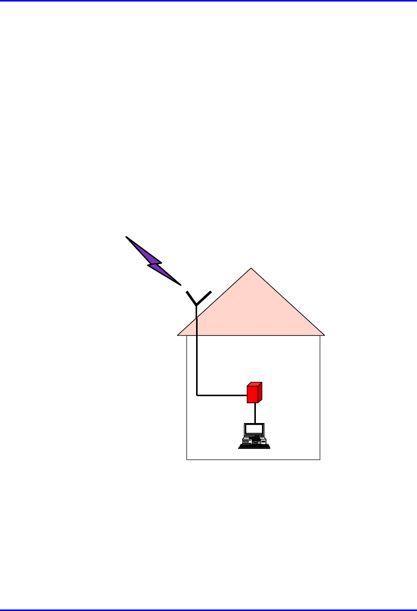
The IDR device is an optional WipLL device that combines the functionality of the
SPR and SDA devices. The IDR has a built-in antenna that provides an interface for
transmission with the base station. In addition, the IDR provides an interface for
10Base-T Ethernet with the subscriber's network. However, unlike the SDA, a
separate power supply unit (power adapter) powers the IDR.
The IDR is available in two models:
! IDR with an internal antenna
! IDR with a TNC connector for connecting to a third-party external antenna
RF link
t
o BSR
Optional external
Optional externalOptional external
Optional external
antenna
antennaantenna
antenna
RF cable
IDR
PC
RF link
t
o BSR
Optional external
Optional externalOptional external
Optional external
antenna
antennaantenna
antenna
RF cable
IDR
PC
Figure 10-1: Typical IDR setup at subscriber's premises (showing optional antenna)

Hardware Installation Guide Installing the IDR
02030311-06 Airspan Networks Ltd. 10-3
Warning: To avoid electrical or fire hazard, ensure that all connections to the
IDR are performed prior to connecting the power supply.
Note: The digital portion of the transceiver has been tested and found to
comply with the limits for a Class B digital device, pursuant to part 15 of the
FCC rules. These limits are designed to provide reasonable protection against
harmful interference in a residential installation. This equipment generates,
uses, and can radiate radio frequency energy and, if not installed and used in
accordance with the instructions, may cause harmful interference to radio
communications. However, there is no guarantee that interference will not
occur in a particular installation. If this equipment does cause harmful
interference to radio or television reception, which can be determined by
turning the equipment on and off, the user is encouraged to try correct the
interference by performing one or more of the following measures:
- Reorientate or relocate the receiving antenna
- Increase separation between the equipment and receiver
- Connect the equipment to an outlet on a circuit different from that to which
the receiver is connected
- Consult the dealer or an experienced radio/TV technician for help
Installing the IDR Hardware Installation Guide
10-4 Airspan Networks Ltd. 02030311-06
10.2. Physical Dimensions and Basic Design
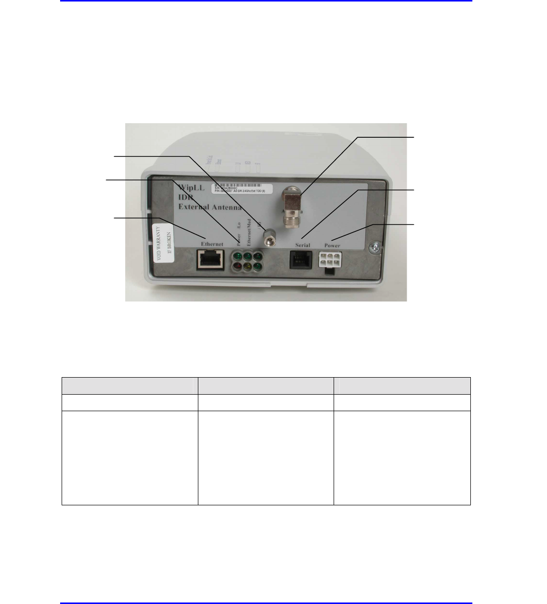
The IDR is encased in a chassis providing access to the IDR's communication port at
the front panel.
Figure 10-2: IDR front panel with cover removed exposing ports
The IDR's physical dimensions are described in Table 10-1.
Table 10-1: IDR physical dimensions
Parameter Value Comment
Weight 1,43 kg
Dimensions (H x W x D)
• IDR with built-in antenna
• IDR with an external
antenna
• 155 mm (6.1 inches) x 233
mm (9.17 inches) x 74.5
mm (2.93 inches)
• 120.5 mm (4.74 inches) x
61mm (2.4 inches) x 35
mm (1.37 inches)
Note: Dimensions exclude the
external power adapter.
TNC-type connector for
3rd party external antenna
RJ-11 serial port
Molex 6-pin power port
LEDs
RJ-45 10Base-T port
Chassis cover bolt
Hardware Installation Guide Installing the IDR
02030311-06 Airspan Networks Ltd. 10-5
10.3. Mounting the IDR
The IDR may be mounted in the following ways:
! Desk
! Pole
! Wall
Note: Before mounting or attaching any brackets to the IDR, ensure that all
cables are securely attached and that the unit functions correctly in the
proposed location.
10.3.1. Desk Mounting
The IDR may be mounted on a desk in one of the following ways:
! Vertically
! Horizontally
Installing the IDR Hardware Installation Guide
10-6 Airspan Networks Ltd. 02030311-06
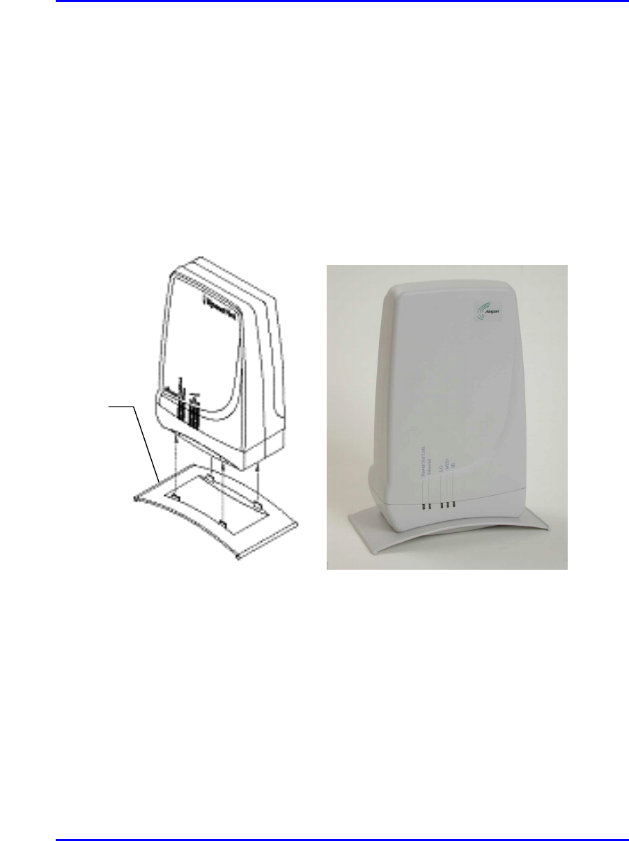
10.3.1.1. Vertical-Desk Mounting
A base plate is provided to mount the unit vertically on the desk, i.e., in standing
position. The base plate is designed to fit in one position only.
To desk mount the IDR in a vertical position:
! Insert the IDR into the base and press firmly until the tabs click into place. See
Figure 10-3.
Figure 10-3: IDR vertical desk mounting
Desk-
mounting
p
late
Hardware Installation Guide Installing the IDR
02030311-06 Airspan Networks Ltd. 10-7
10.3.1.2. Horizontal-Desk Mounting
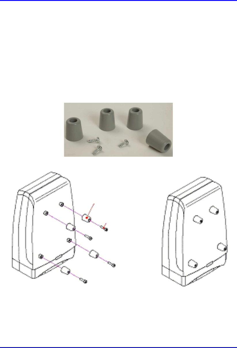
To position the IDR horizontally on the desk, four rubber pads, supplied with the
unit, must be fitted to avoid damage to mounting surfaces.
mTo desk mount the IDR in a horizontal position:
! Secure the rubber pads to the posts provided on the rear of the IDR using four
self-tapping screws. See Figure 10-4.
Figure 10-4: IDR horizontal desk mounting using supplied rubber pads and tapping
screws
Rubber foot
Screw
Installing the IDR Hardware Installation Guide
10-8 Airspan Networks Ltd. 02030311-06
10.3.2. Wall and Pole Mounting
The IDR may be mounted to a wall or to a 5-cm diameter pole. Wall and pole
mounting both use the same mounting brackets and wall hanger plate.
10.3.2.1. Assembling the Bracket and Hanger Plate
The wall hanger plate secures the IDR to a wall or pole. The wall bracket and hanger
plate allows positioning the IDR in the correct orientation. Holes are provided in the
wall hanger plate for both pole and wall mounting options
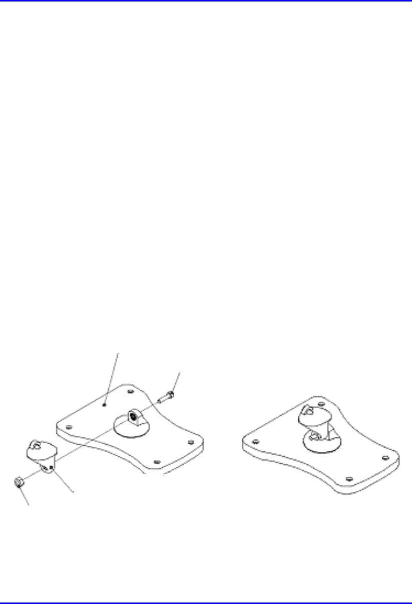
To assemble the bracket and hanger plate:
1. Insert a 4 mm hex nut into the slot on the tilt arm component
2. Holding the nut in place, attach the tilt arm to the mounting bracket using a 4
mm socket head bolt. Hand tighten the bolt only. See Figure 10-5.
3. Affix the complete mounting assembly to the rear of the IDR using the 4-off
self-tapping screws supplied with the kit.
Figure 10-5: Mounting bracket assembly
Mounting Bracket
Screw
Tilt Arm
N
ut
Hardware Installation Guide Installing the IDR
02030311-06 Airspan Networks Ltd. 10-9
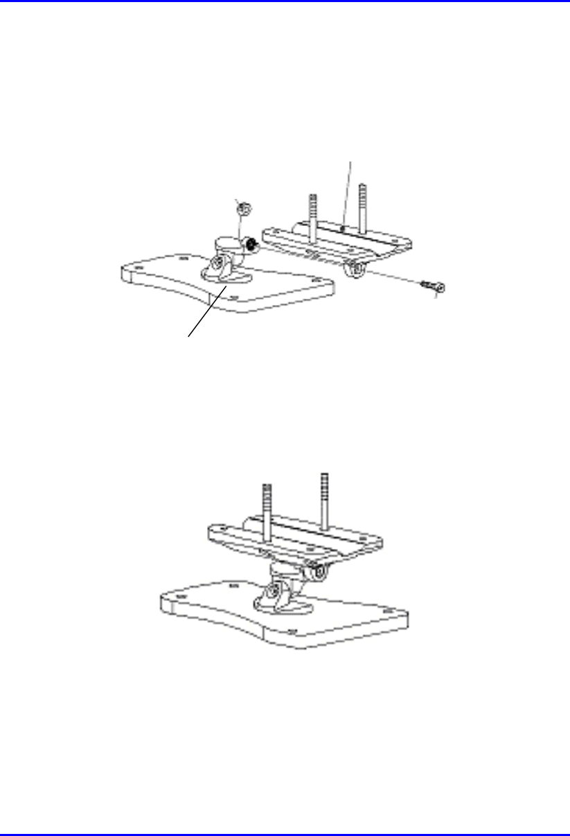
4. Attach the wall bracket assembly to wall hanger using an M4 socket-head bolt
and nut as shown in Figure 10-6. The bolt is only to be hand tightened at this
stage.
Wall Hanger
M-4 nut
Screw
Mounting bracket
assembly
Figure 10-6: Wall hanger fixing method
Figure 10-7: Wall hanger & mounting bracket assembly
Installing the IDR Hardware Installation Guide
10-10 Airspan Networks Ltd. 02030311-06
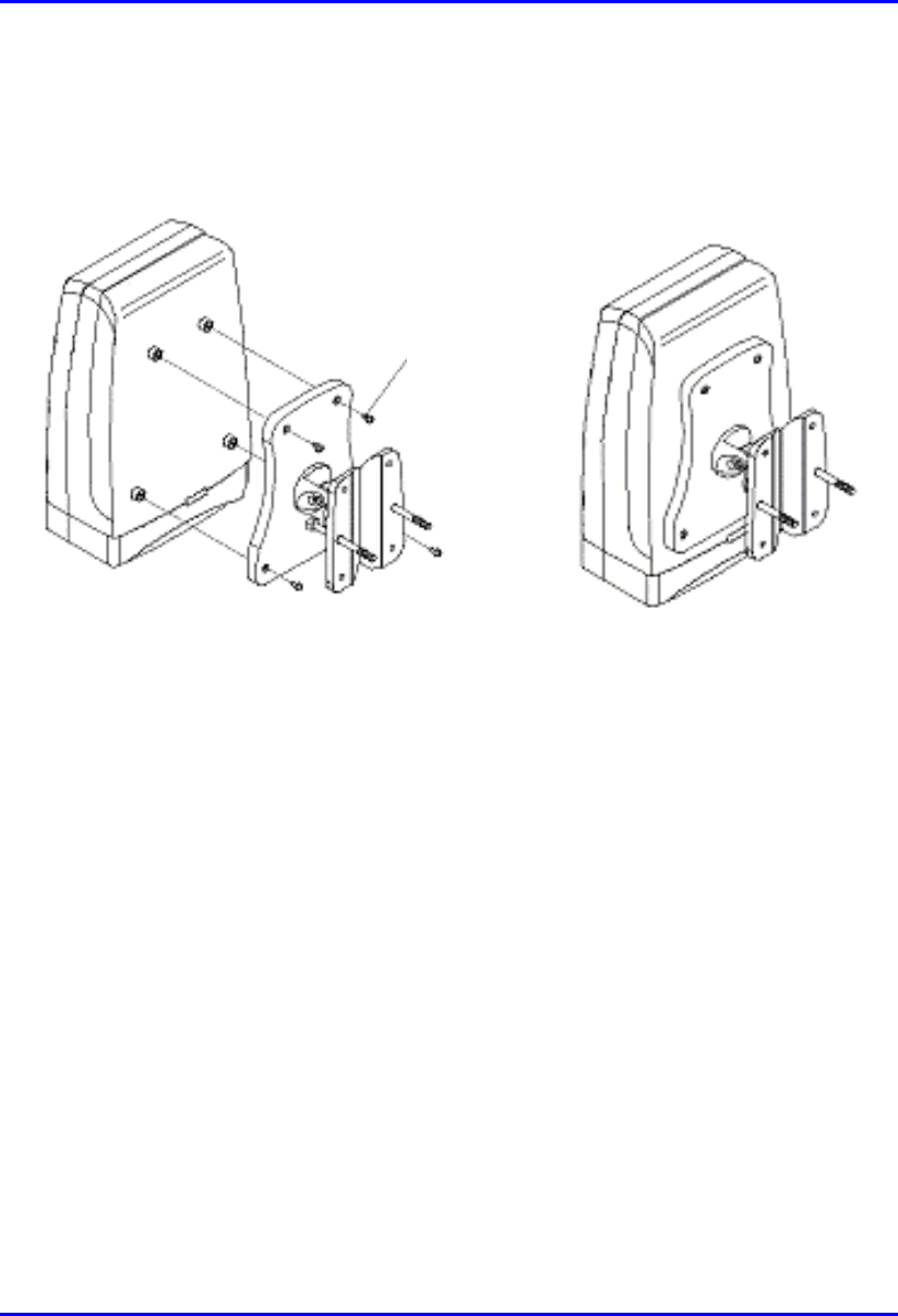
5. Once assembled, the IDR mounting bracket assembly may be secured to the rear
of the IDR using the 4-off self-tapping screws supplied in the unit fixing kit. See
Figure 10-8.
Figure 10-8: Mounting bracket assembly secured to IDR
Self -
tapping
Screws
Hardware Installation Guide Installing the IDR
02030311-06 Airspan Networks Ltd. 10-11
10.3.2.2. Pole Mounting
Prior to mounting the IDR to a pole the wall mounting bracket assembly must be
fitted as described in the previous section.
To pole mount the IDR:
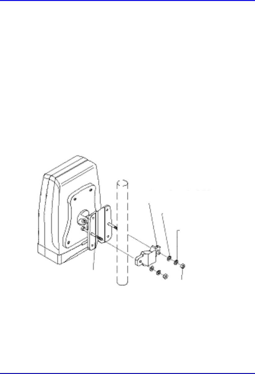
1. Offer up the IDR assembly to the pole as shown in Figure 10-9.
2. Insert 2-off M10 bolts through the holes in the wall hanger.
3. Slide the clamp-holder into position and secure using washers, spring-washers
and nuts as illustrated in Figure 10-10. Finger-tighten the fasteners.
4. Slide the IDR to the required location on the pole and fully tighten the fasteners.
Figure 10-9: IDR pole mounting components
Clam
p
holde
r
Washe
r
Spring
Washe
r
Hex Nut
Bol
t
Installing the IDR Hardware Installation Guide
10-12 Airspan Networks Ltd. 02030311-06
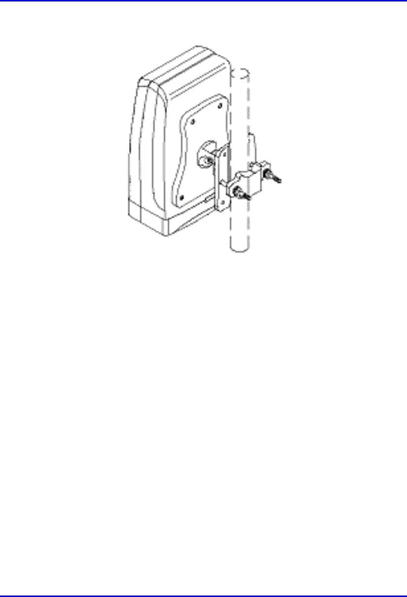
Figure 10-10: IDR secured to a pole
To set the correct IDR inclination:
1. Loosen the 2-off M4 socket head screws on the mounting bracket tilt-arm
2. Position the IDR at the desired angle.
3. Re-tighten the 2 off socket screws on the tilt arm.

Hardware Installation Guide Installing the IDR
02030311-06 Airspan Networks Ltd. 10-13
10.3.2.3. Wall Mounting
Warning: Prior to drilling holes in a wall ensure that there are no hidden
services such as electricity cables or water pipes. A stop must be used on the
power drill to ensure that bored holes do not exceed 35 mm.
To mount the IDR on a wall:
1. Loosen the 2-off M4 socket head screws on the mounting bracket tilt-arm and
remove the wall hanger.
2. Offer up the wall hanger to the wall and scribe through the mounting hole
locations.
3. Drill holes to suit the type of wall fixing.
4. If required insert anchor plugs suited to the wall material.
5. Affix the wall hanger using 4-off screws suited to the anchor plugs and wall
material.
6. Re-attach the IDR mounting bracket to the wall hanger. Finger tighten the
screws.
7. Position the IDR at the desired inclination.
8. Re-tighten the screws to lock the IDR in position.
Installing the IDR Hardware Installation Guide
10-14 Airspan Networks Ltd. 02030311-06
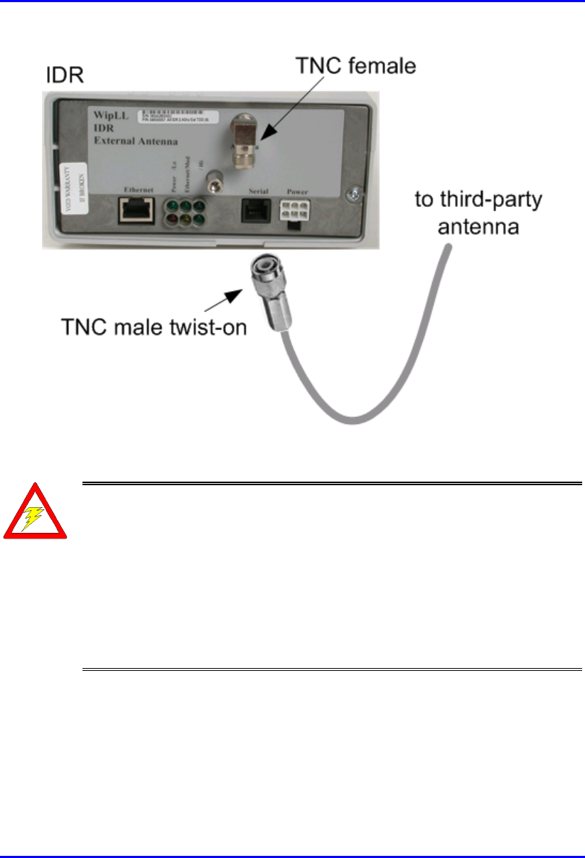
10.4. Connecting a Third-Party External
Antenna
The IDR provides a TNC-type connector for connecting a third-party antenna to the
IDR. This antenna can be placed on the subscriber’s windowsill to provide better RF
signal reception with the BSR.
Note: Airspan supplies unterminated cables for N-type connectors. Therefore,
refer to the cable crimping procedures for N-type connectors detailed in
Appendix B, “Cable Crimping".
! Connector: TNC-type male
Warning: Before connecting the external antenna, ensure that the IDR is NOT
connected to the power source.
Hardware Installation Guide Installing the IDR
02030311-06 Airspan Networks Ltd. 10-15
Figure 10-11: Connecting a third-party antenna
Warnings:
1) It is the responsibility of the person installing the WipLL system to ensure
that when using the outdoor antenna kits in the United States (or where FCC
rules apply), that only those antennas certified with the product are used. The
use of any antenna other than those certified with the product is expressly
forbidden in accordance with FCC rules CFR47 part 15.204. The installer
should configure the output power level of antennas according to country
regulations and per antenna type.
2) Indoor units and antennas should be installed ONLY by experienced installation
professionals who are familiar with the local building and safety codes and are licensed
by the appropriate government authorities.
Installing the IDR Hardware Installation Guide
10-16 Airspan Networks Ltd. 02030311-06
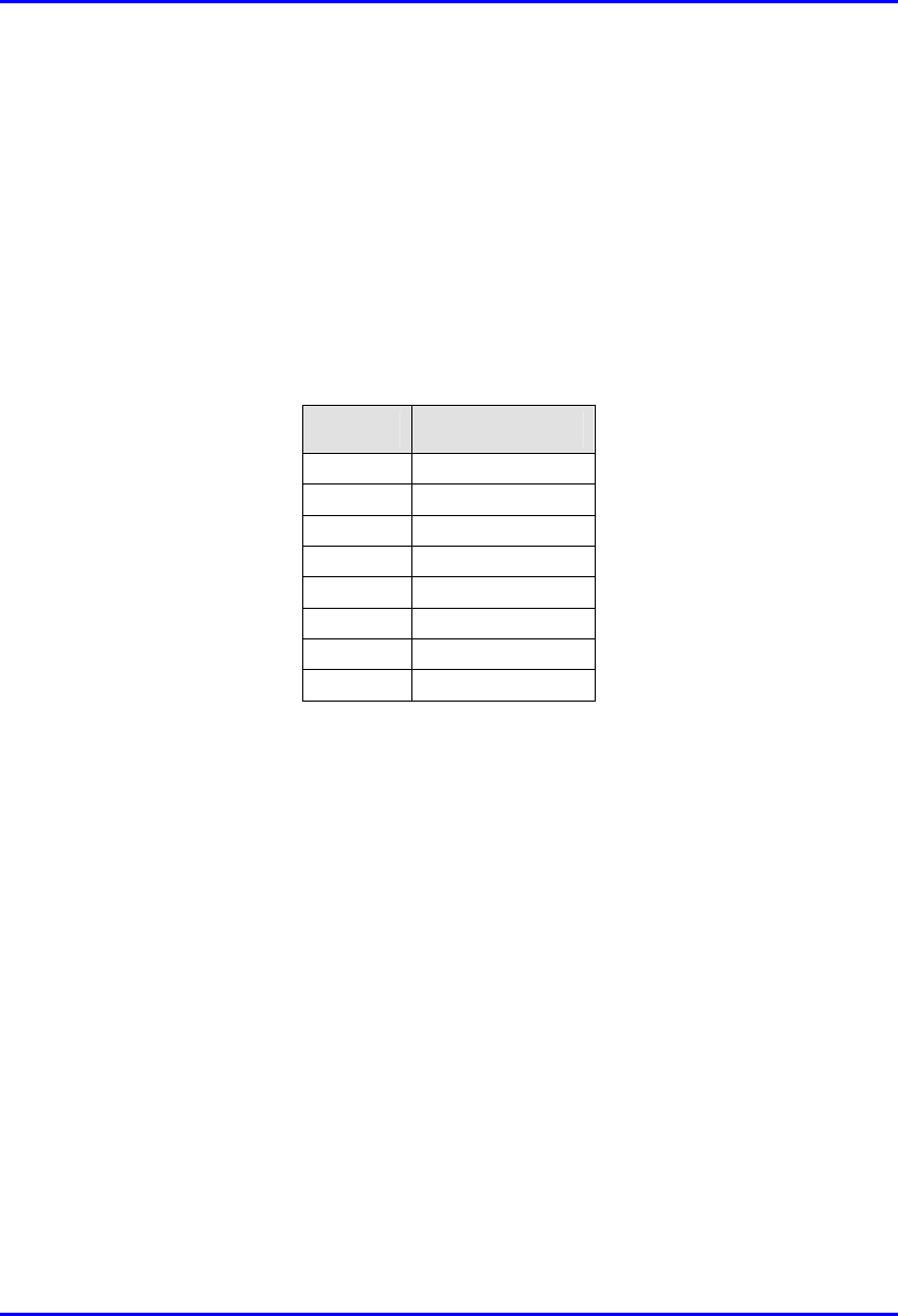
10.5. Connecting to an Ethernet Network
The IDR provides one Ethernet interface for the subscriber’s Ethernet network. This
port is located on the front panel, and labeled Ethernet.
! Connector: 8-Pin RJ-45
! Cable: CAT-5
! Connector pinouts:
Pin Function
1 Rx+
2 Rx-
3 Tx+
4
N
ot Connected
5
N
ot Connected
6 Tx-
7
N
ot connected
8
N
ot connected
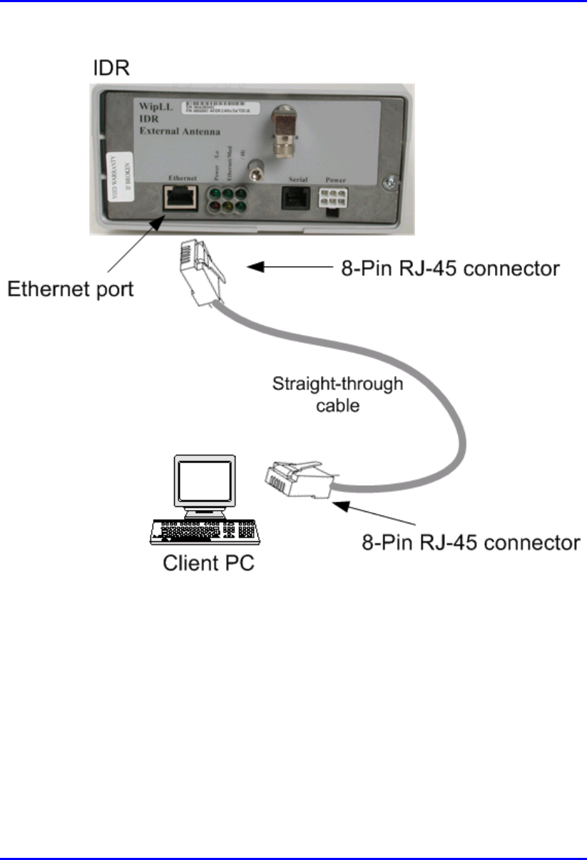
To connect IDR to the subscriber’s Ethernet network:
1. Attach the 8-pin RJ-45 connector, at one end of the cable, to the IDR's Ethernet
port, labeled Ethernet (see Figure 10-12).
2. Attach the 8-pin RJ-45 connector, at the other end of the cable, to the PC's LAN
port (see Figure 10-12).
Hardware Installation Guide Installing the IDR
02030311-06 Airspan Networks Ltd. 10-17
Figure 10-12: Connecting IDR to a client PC
Installing the IDR Hardware Installation Guide
10-18 Airspan Networks Ltd. 02030311-06
10.5.1. Ethernet LED Indicator
The IDR provides one LED that indicates an Ethernet connection. This LED is
labeled Ethernet and is located on the IDR’s top panel.
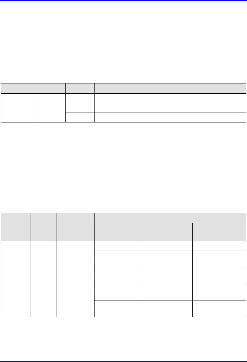
Table 10-2: Description of Ethernet LEDs
LED Color Status Indicates
On Physical link between IDR and Ethernet network
Off No physical link between IDR and Ethernet network
Ethernet Orange
Blinking Data is flowing through the Ethernet port
10.6. Positioning IDR for Optimum RF
Reception
Once mounted to a wall, pole, or desk the IDR unit may be positioned to ensure the
best RF signal communication with the BSR. The RF signal strength is indicated by
three LEDs on the IDR chassis. The following table describes the RF signaling
strength indicator LEDs.
Table 10-3: Description of RF signal strength LEDs
Description LED Color Function Status
Previous
Releases
Release 4.2B
All LEDs On RSSI ≥ -60 dBm RSSI ≥ -60 dBm
Two LEDs On -65 dBm ≤ RSSI ≤
-61 dBm
-70 dBm ≤ RSSI <
-60 dBm
One LED On -70 dBm ≤ RSSI ≤
-66 dBm
-80 dBm ≤ RSSI <
-70 dBm
One LED
Blinking
RSSI ≤ -77 dBm -90 dBm ≤ RSSI <
-80 dBm
RSSI
LEDs:
LO,
MED,
and HI
Green RSSI level
All LEDs Off -76 dBm ≤ RSSI ≤
-71 dBm
RSSI < -90 dBm
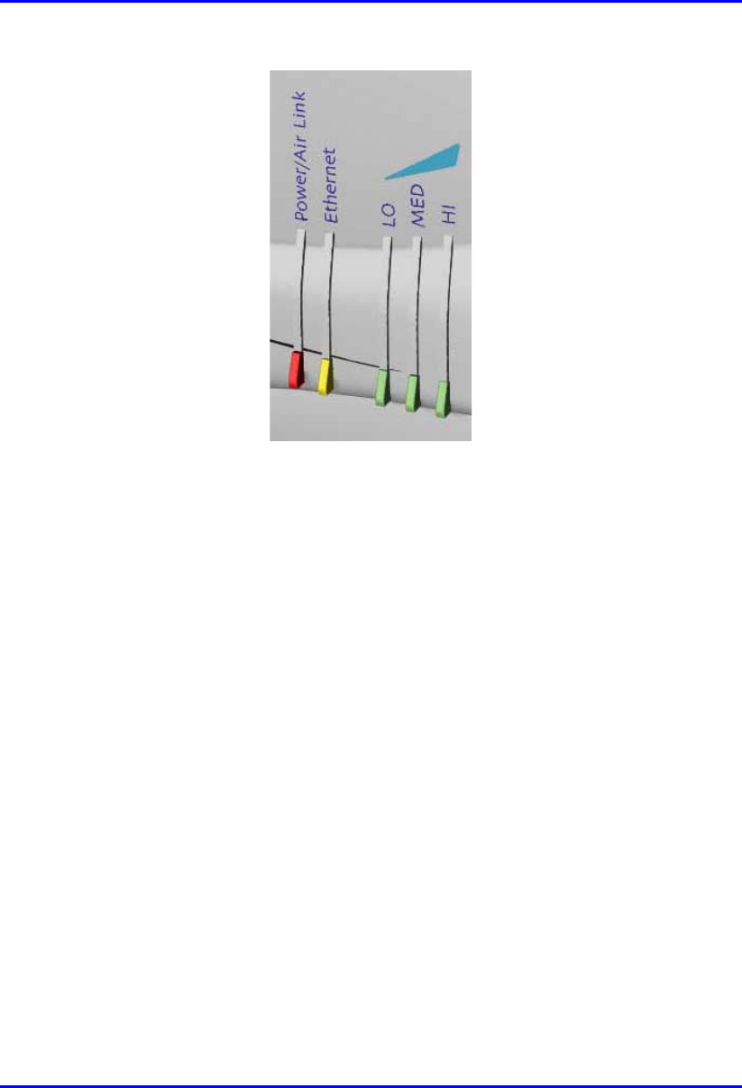
Hardware Installation Guide Installing the IDR
02030311-06 Airspan Networks Ltd. 10-19
Figure 10-13: IDR LED indicators
To position the IDR for optimum RF signal:
! Position the IDR until all three RF signaling strength indicator LEDs are lit.
Refer to Section 10.3.2, “Wall and Pole Mounting” page 10-8 for details on
adjusting IDR wall and pole mounting position.
For desk-top mounting, the IDR can be simply relocated to obtain the strongest
signal.

Installing the IDR Hardware Installation Guide
10-20 Airspan Networks Ltd. 02030311-06
10.7. Connecting to PC for Serial Configuration
To perform IDR initial configuration, you need to connect the IDR’s RJ-11 port to
the serial port of a PC running the WipLL network management application (i.e.,
WipConfig).
The IDR’s RJ-11 port labeled Serial, located on the front panel, connects to the
serial port of a PC via a cable with an RJ-11 connector on the one end, and a 9-Pin
D-type connector on the other (i.e., a direct serial cable connection-DCC).
! Connectors:
! 6-Pin RJ-11 male to 9-pin D-type female adapter
! 9-Pin D-type male to 9-Pin D-type female adapter
! Cable:
! Straight-through cable with 6-Pin RJ-11 male on one end and 9-Pin D-type
female on the other (connects between IDR and crossover cable)
! Crossover cable with 9-Pin D-type male on one end and 9-Pin D-type
female on the other (connects straight-through cable to PC)
Hardware Installation Guide Installing the IDR
02030311-06 Airspan Networks Ltd. 10-21
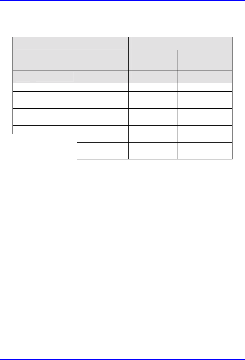
! Connector pinouts:
Straight-through cable Crossover cable
6-Pin RJ-11 9-Pin D-type
female
9-Pin D-type
male
9-Pin D-type
male
Pin Function Pin Pin Pin
1 Rx 2 4 3
2
N
ot connected - - -
3
N
C - - -
4
N
C - - -
5 GND 5 1 5
6 Tx 3 3 2
- - -
- - -
- - -
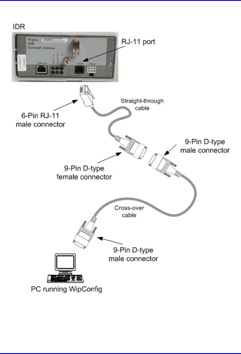
To connect the IDR to the WipLL management station (PC):
1. Connect the 6-Pin RJ-11 connector to the IDR’s RJ-11 port (labeled Serial)
located on the IDR’s front panel (see Figure 10-14).
2. Connect the 9-Pin D-type female connector, at the other end of the straight-
through cable, to the 9-Pin D-type male connector of the cross-over cable (see
Figure 10-14).
3. Connect the 9-Pin D-type male connector, at the other end of the cross-over
cable, to the PC’s serial port (see Figure 10-14).
Installing the IDR Hardware Installation Guide
10-22 Airspan Networks Ltd. 02030311-06
Figure 10-14: IDR-to-PC Serial Cable Connections
Hardware Installation Guide Installing the IDR
02030311-06 Airspan Networks Ltd. 10-23
10.8. Connecting Power
The IDR is powered by an external power supply (Triple Output External Adapter).
The IDR connects to the power adapter via the IDR's power port located on the
IDR’s front panel.
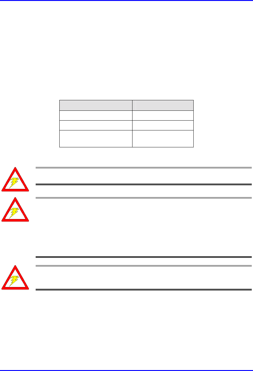
The following table lists the external power supply specifications:
Table 10-4: IDR power supply requirements
Power parameter Units
Voltages 110-240 VAC
Frequency 50 to 60Hz
Maximum power
consumption
Less than 15W
Warning: If you are using an external antenna, ensure that you connect the
antenna before connecting the BSR to the power source.
Warning: Ensure that plugs fitted to mains power leads for subscriber
premises equipment are compatible with AC mains sockets. Do not replace
plugs on power leads to suit local requirements without first verifying earthing
practice for the country and equipment in question.
Careful consideration must be given to issues including local wiring
requirements, cable color-coding, and safety earthing and circuit protection
requirements.
Warning: To avoid electrical or fire hazard, ensure that the data connections
to the IDR are made prior to connecting the power supply.The AC mains must
be capable of supplying at least 230 VAC
Prior to connecting to the power outlet, the following pre-connection inspection
should be performed on power sockets:
! Power socket shall be visually inspected to ensure that no other equipment is
connected to the power outlet.
Installing the IDR Hardware Installation Guide
10-24 Airspan Networks Ltd. 02030311-06
! There is no physical sign of damage to the power outlet.
! There should not be any visible sign of water or dampness on or around the
power outlet.
! The plug and socket assemblies are to be firmly secured.
! The power outlet shall be checked using a proprietary plug tester such as a
‘Martindale Ze’ type. Checks are required to verify the earth loop impedance
value and the presence of phase, neutral and earth connections.
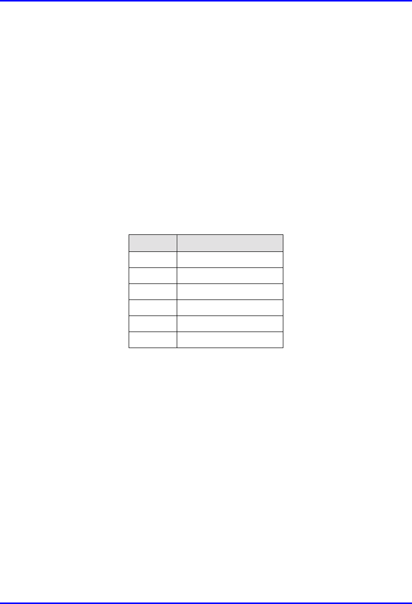
! Connector: 6-Pin power connector
! Cable: 3-core 0.7mm² type
! Connector pinouts:
Pin Function
1 +6.5V
2 +5V
3 3.3V
4 GND
5 Not connected
6 Not connected
To connect the power:
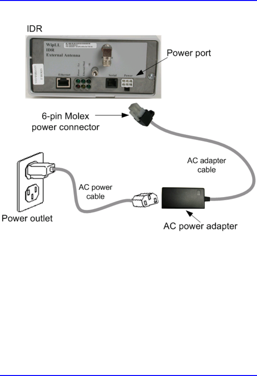
1. Plug the AC power adapter’s 6-pin Molex connector into the IDR’s power port
labeled Power (see Figure 10-15).
2. Plug the AC power plug female, at the one end of the AC power cable, into the
AC power adapter’s socket (see Figure 10-15).
3. Plug the AC power plug male, at the other end of the AC power cable, into the
electrical outlet (see Figure 10-15).
Hardware Installation Guide Installing the IDR
02030311-06 Airspan Networks Ltd. 10-25
Figure 10-15: Connecting power to the IDR
Installing the IDR Hardware Installation Guide
10-26 Airspan Networks Ltd. 02030311-06
10.8.1. Power LEDs
The IDA provides a power LED indicator, labeled Power, which indicates whether a
power supply exists. The Power LED is located on the front panel of the IDR
chassis.
Table 10-5: Description of Power LEDs
LED Color Status Meaning
On The SDA receives power supply
Power Red
Off No power received