Airspan Networks AIRSPAN-IDR Indoor Data Radio (IDR) User Manual Chapter 10 Revised
Airspan Networks Inc Indoor Data Radio (IDR) Users Manual Chapter 10 Revised
UserManual.wiki
>
Airspan Networks
>
AIRSPAN-IDR User Manual
>
Users Manual Chapter 10 Revised
Contents
1.
DoC
2.
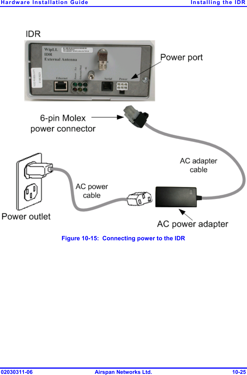
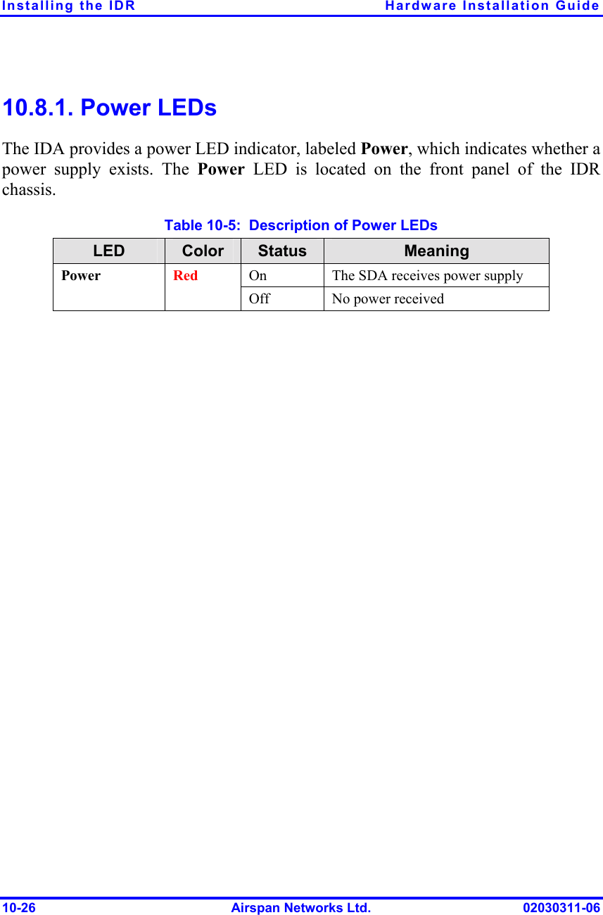
Users Manual Chapter 10 Revised
3.
Users Manual Chapter 2 Revised
4.
Appendix C
5.
Appendix E
6.
Install Guide Part 1
7.
Install Guide Part 3
8.
Users Manual Part 2A
9.
Users Manual Part 2B
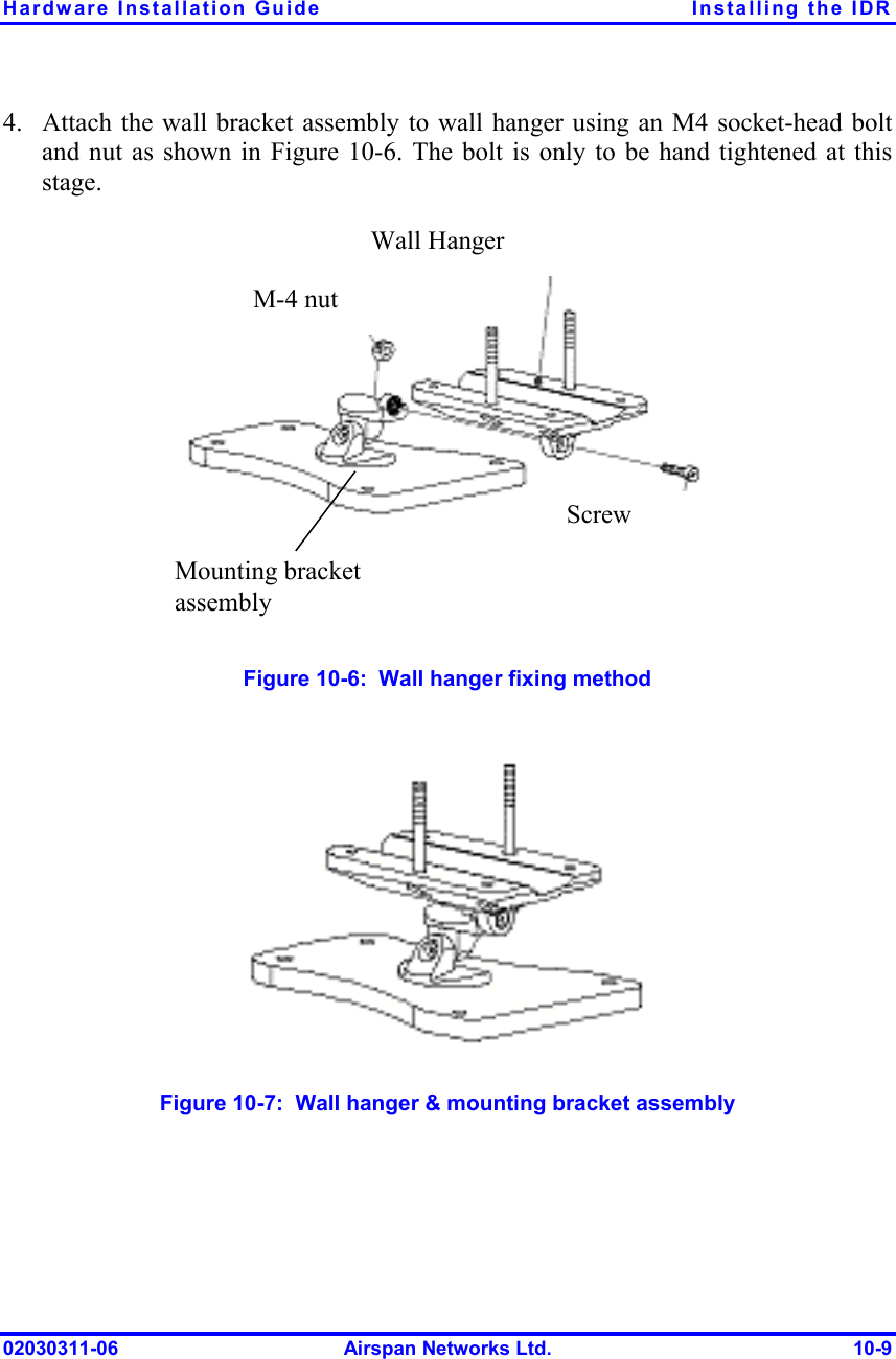
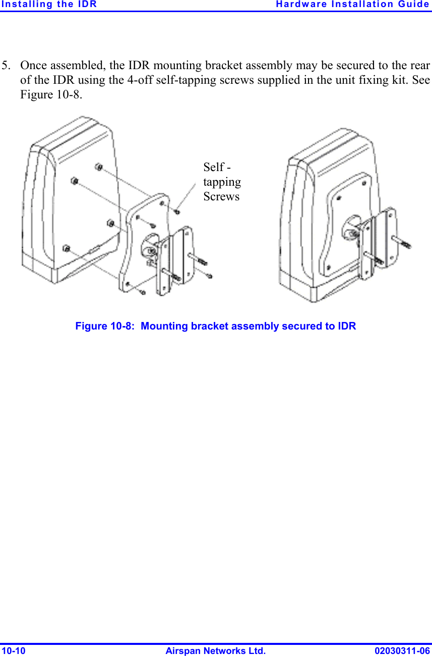
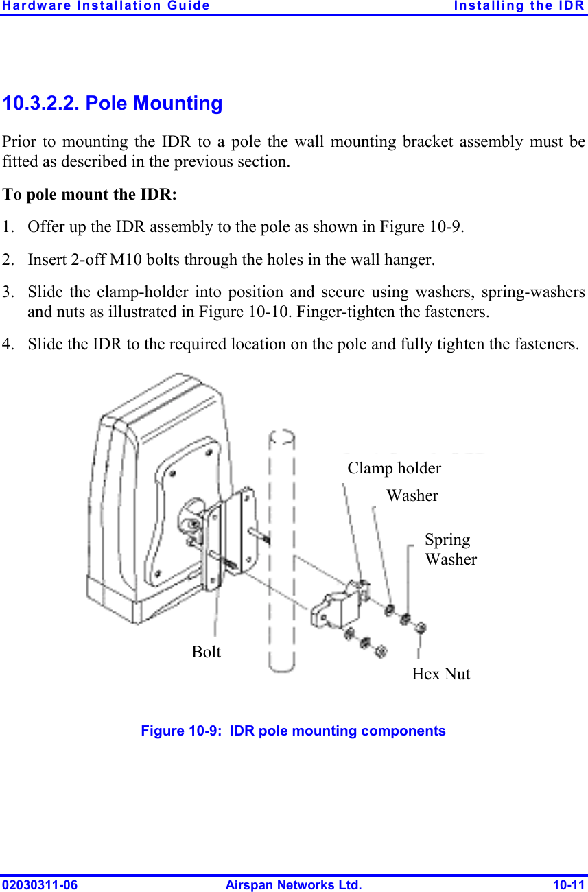
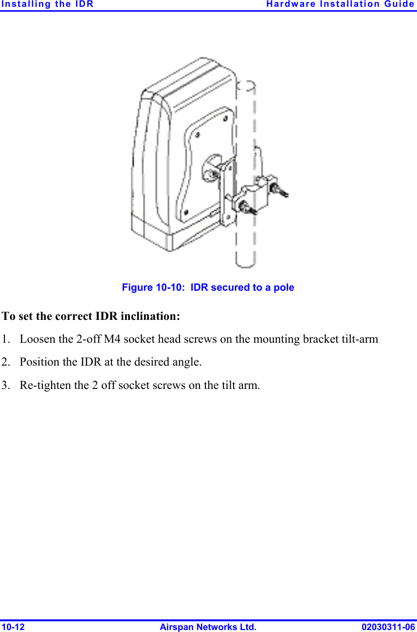
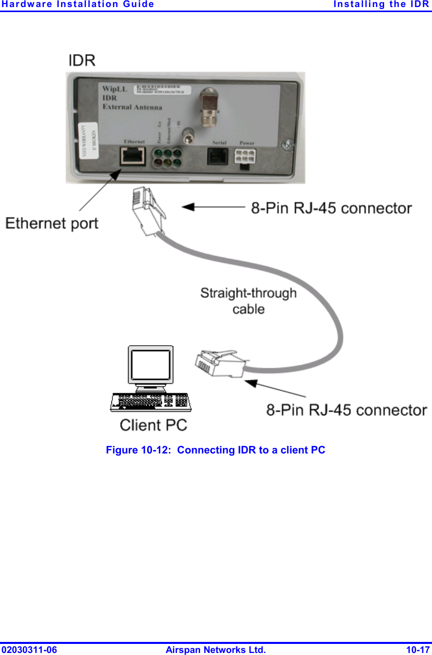
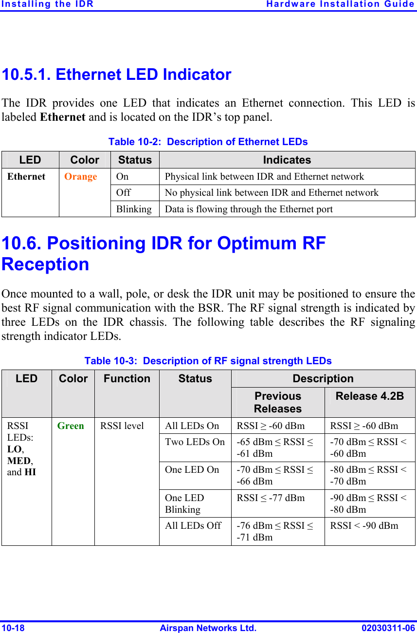
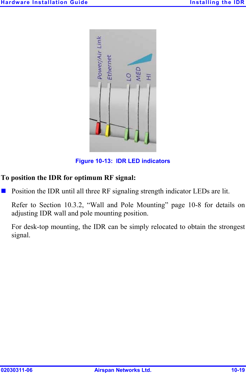
Users Manual Chapter 10 Revised
Navigation menu
Upload a User Manual
Namespaces
Wiki Guide
HTML
PDF
Info
Views
User Manual
Discussion / Help
Navigation