Airspan Networks AIRSPAN-IDR900 Indoor Data Radio (IDR) User Manual SysDescr hh
Airspan Networks Inc Indoor Data Radio (IDR) SysDescr hh
Contents
- 1. Installation Safety Revised
- 2. Installation Revised
- 3. External Antenna Information
- 4. Internal Antenna Information
External Antenna Information

25030311-08 Airspan Networks Inc. H-1
External Antennas
Specifications
This appendix provides specifications for optional third-party external antennas for
WipLL devices operating in the 900 MHz and 700 MHz bands.
H.1. WipLL 900 MHz
H.1.1. BSR (at Base Station)
Airspan offers the following optional third-party external antennas for BSR devices
operating in the 900 MHz band:
Panel 35°/ 18.6 dBi
Panel 120°/16 dBi
Panel 62°/16 dBi
Panel 90°/17 dBi
Omni-Directional 360°/12 dBi (3° Lobe Tilt)
Omni-Directional 360°/12 dBi (5° Lobe Tilt)
Sector (65°/15.5 dBi)
Omni-directional (11 dBi)
H
External Antennas Specifications System Description
H-2 Airspan Networks Inc. 25030311-08
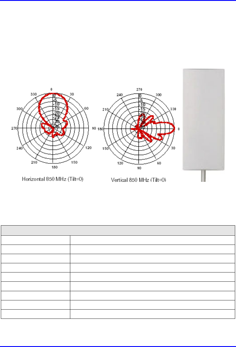
H.1.1.1. Panel 35°/ 18.6 dBi
The Panel 35°/ 18.6 dBi antenna’s radiation pattern and physical design is shown in
the figure below.
Figure H-1: Panel 35°/ 18.6 dBi antenna radiation pattern
The table below lists the Panel 35°/ 18.6 dBi antenna specifications.
Table H-1: Panel 35°/ 18.6 dBi antenna specifications
Electrical specifications
Frequency range 870 – 960 MHz
Polarization Vertical
Gain (dBd/dBi) 16.5/18.6
Azimuth BW 35°
Elevation BW 14.5°
Beam Tilt 0°
USLS (dB) >18
Front-to-Back Ratio (dB) 25
VSWR <1.33:1

System Description External Antennas Specifications
25030311-08 Airspan Networks Inc. H-3
Electrical specifications
IM Suppression – Two 20
Watt Carriers
-150 dBc
Impedance 50 Ω
Max. Input Power 500 Watts
Lightening Protection DC Ground
Mechanical specifications
Weight 17.5 lbs (7.9 kg)
Dimensions (LxWxD) 48.5 x 18.5 x 5 in. (1232 x 470 x 127 mm)
Max. Wind Area 5.3 ft2 (0.49 m2)
Max. Wind Load (at 100
mph)
213 lbf (947 N)
Max. Wind Speed 125 mph (201 km/h)
Radiator Material Aluminum
Radome Material ABS, UV Resistant
Mounting Hardware
Material
Galvanized Steel
Connector Type 7/16 DIN (Back)
Color Light gray
Standard Mounting
Hardware
DB380 Pipe Mount Kit, included
Downtilt Mounting
Hardware
DB5083, optional
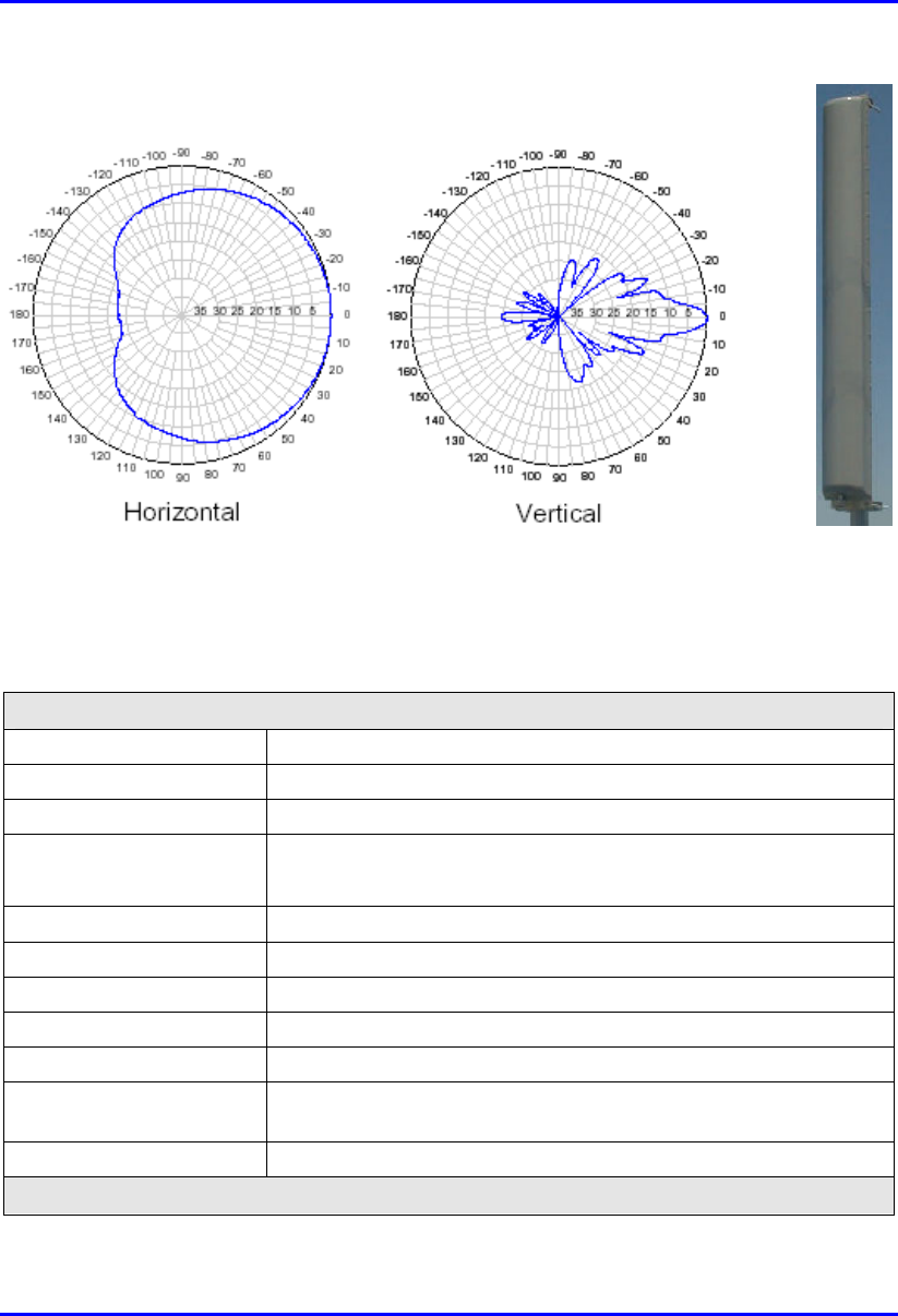
H.1.1.2. Panel 120°/16 dBi
The Panel 120°/16 dBi antenna’s radiation pattern and physical design is shown in
the figure below.
External Antennas Specifications System Description
H-4 Airspan Networks Inc. 25030311-08
Figure H-2: Panel 120°/16 dBi antenna radiation pattern (at mid-band)
The table below lists the Panel 120°/16 dBi antenna specifications.
Table H-2: Panel 120°/16 dBi antenna specifications
Electrical specifications
Frequency range 806 – 960 MHz
Polarization Vertical
Gain 16 dBi
Half-power beam width • H-plane: 120°
• E-plane: 7°
Impedance 50Ω
VSWR <1.4:1
Max. Power 500 W (limited by connector only)
Lobe Tilt 1.25°
Null Fill 25%
Connector N, NE (elongated N connector), DIN, EDIN (elongated DIN
connector)
Lightning Protection Direct ground
Mechanical specifications
System Description External Antennas Specifications
25030311-08 Airspan Networks Inc. H-5
Electrical specifications
Wind area 0.73 m2 (7.87 ft2)
Weight 14 kg (31 lbs)
Wind load at 50 m/s 1140 N (256 lbs)
Depth 160 mm (6.3 in.)
Width 295 mm (11.6 in.)
Length 2450 mm (96.5 in.)
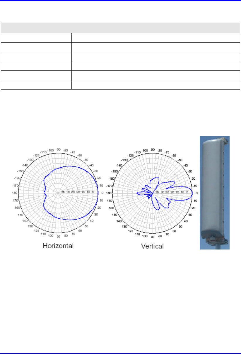
H.1.1.3. Panel 62°/16 dBi
The Panel 62°/16 dBi antenna’s radiation pattern and physical design is shown in the
figure below.
Figure H-3: Panel 62°/16 dBi antenna radiation pattern (at mid-band)

External Antennas Specifications System Description
H-6 Airspan Networks Inc. 25030311-08
The table below lists the Panel 62°/16 dBi antenna specifications.
Table H-3: Panel 62°/16 dBi antenna specifications
Electrical specifications
Frequency range 806 – 960 MHz
Polarization Vertical
Gain 16 dBi
Half-power beam width • H-plane: 62°
• E-plane: 14°
Impedance 50Ω
VSWR <1.4:1
Max. Power 500 W (limited by connector only)
Lobe Tilt 1.25°
Null Fill 5%
Connector N, NE (elongated N connector), DIN, EDIN (elongated DIN
connector)
Lightning Protection Direct ground
Mechanical specifications
Wind area 0.36 m2 (3.9 ft2)
Weight 6.5 kg (14.3 lbs)
Wind load at 50 m/s 560 N (126 lbs)
Depth 160 mm (6.3 in.)
Width 295 mm (11.6 in.)
Length 1225 mm (48.2 in.)
System Description External Antennas Specifications
25030311-08 Airspan Networks Inc. H-7
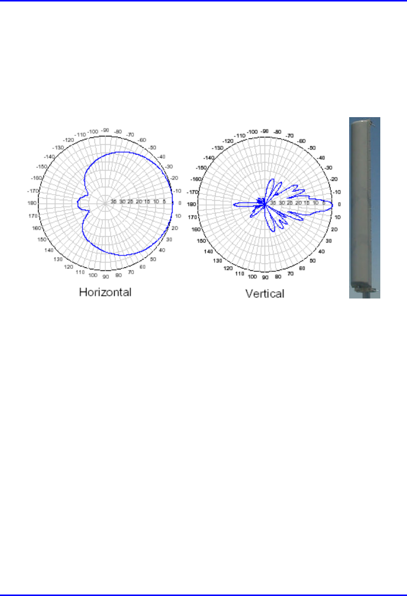
H.1.1.4. Panel 90°/17 dBi
The Panel 90°/17 dBi antenna’s radiation pattern and physical design is shown in the
figure below.
Figure H-4: Panel 90°/17 dBi antenna radiation pattern (at mid-band)

External Antennas Specifications System Description
H-8 Airspan Networks Inc. 25030311-08
The table below lists the Panel 90°/17 dBi antenna specifications.
Table H-4: Panel 90°/17 dBi antenna specifications
Electrical specifications
Frequency range 806 – 960 MHz
Polarization Vertical
Gain 17 dBi
Half-power beam width • H-plane: 90°
• E-plane: 7°
Impedance 50Ω
VSWR <1.4:1
Max. Power 500 W (limited by connector only)
Lobe Tilt 1.25°
Null Fill 25%
Connector N, NE (elongated N connector), DIN, EDIN (elongated DIN
connector)
Lightning Protection Direct ground
Mechanical specifications
Wind area 0.73 m2 (7.87 ft2)
Weight 14 kg (31 lbs)
Wind load at 50 m/s 1140 N (256 lbs)
Depth 160 mm (6.3 in.)
Width 295 mm (11.6 in.)
Length 2450 mm (96.5 in.)
System Description External Antennas Specifications
25030311-08 Airspan Networks Inc. H-9
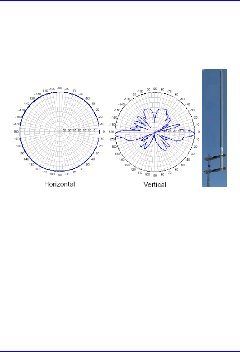
H.1.1.5. Omni-Directional 360°/12 dBi (3° Lobe Tilt)
The Omni-Directional 360°/12 dBi (3° Lobe Tilt) antenna’s radiation pattern and
physical design is shown in the figure below.
Figure H-5: Omni-Directional 360°/12 dBi (3° Lobe Tilt) radiation pattern (at mid-band)

External Antennas Specifications System Description
H-10 Airspan Networks Inc. 25030311-08
The table below lists the Omni-Directional 360°/12 dBi (3° Lobe Tilt) antenna
specifications.
Table H-5: Omni-Directional 360°/12 dBi (3° Lobe Tilt) antenna specifications
Electrical specifications
Frequency range 870 – 960 MHz
Polarization Vertical
Gain 12 dBi
Half-power beam width • H-plane: 360°
• E-plane: 7°
Impedance 50Ω
VSWR <1.43:1
Max. Power 500 W (limited by connector only)
Lobe Tilt 3°
Null Fill 25%
Connector N, NE (elongated N connector), DIN, EDIN (elongated DIN
connector)
Lightning Protection Direct ground
Mechanical specifications
Wind area 0.2 m2 (2.4 ft2)
Weight 12 kg (26.5 lbs)
Wind load at 50 m/s 351 N (79 lbs)
Length:
• Overall
• Radome
• 3393 mm (134 in.)
• 2893 (114 in.)
Diameter ∅65 mm (2.6 in.)
System Description External Antennas Specifications
25030311-08 Airspan Networks Inc. H-11
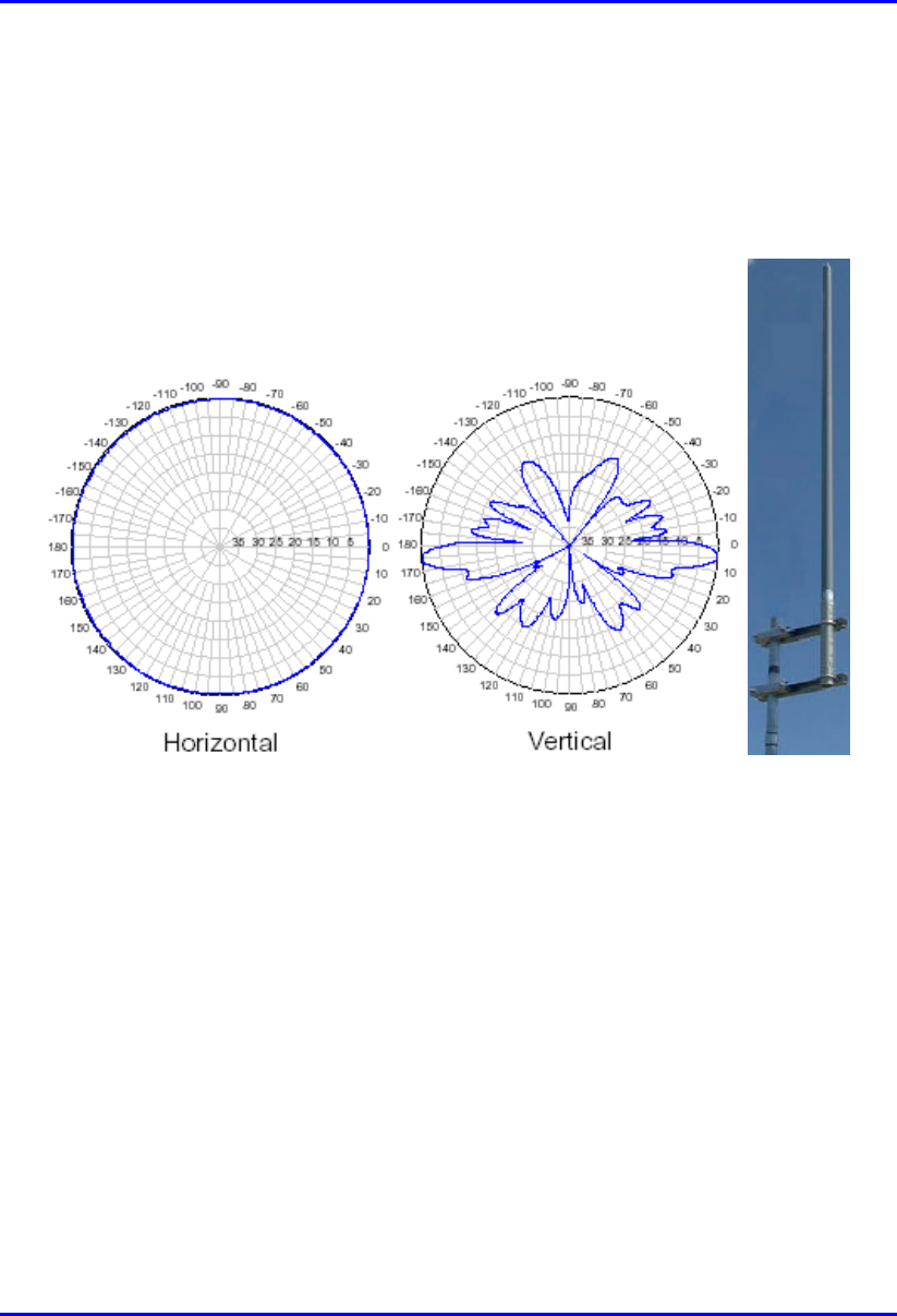
H.1.1.6. Omni-Directional 360°/12 dBi (5° Lobe Tilt)
The Omni-Directional 360°/12 dBi (5° Lobe Tilt) antenna’s radiation pattern and
physical design is shown in the figure below.
Figure H-6: Omni-Directional 360°/12 dBi (5° Lobe Tilt) radiation pattern (at mid-band)

External Antennas Specifications System Description
H-12 Airspan Networks Inc. 25030311-08
The table below lists the Omni-Directional 360°/12 dBi (5° Lobe Tilt) antenna
specifications.
Table H-6: Omni-Directional 360°/12 dBi (5° Lobe Tilt) antenna specifications
Electrical specifications
Frequency range 870 – 960 MHz
Polarization Vertical
Gain 12 dBi
Half-power beam width • H-plane: 360°
• E-plane: 7°
Impedance 50Ω
VSWR <1.43:1
Max. Power 500 W (limited by connector only)
Lobe Tilt 5°
Null Fill 25%
Connector N, NE (elongated N connector), DIN, EDIN (elongated DIN
connector)
Lightning Protection Direct ground
Mechanical specifications
Wind area 0.2 m2 (2.4 ft2)
Weight 12 kg (26.5 lbs)
Wind load at 50 m/s 351 N (79 lbs)
Length:
• Overall
• Radome
• 3393 mm (134 in.)
• 2893 (114 in.)
Diameter ∅65 mm (2.6 in.)
System Description External Antennas Specifications
25030311-08 Airspan Networks Inc. H-13
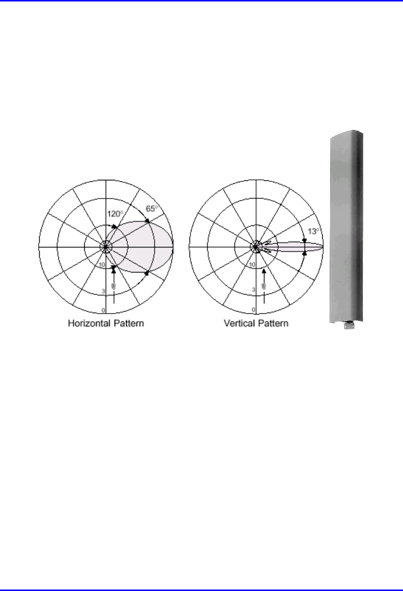
H.1.1.7. Sector Antenna (65°/15.5 dBi)
This antenna is designed for best non-line of sight performance with Airspan’s BSR
operating in the 900 MHz band. Advanced features include: high gain and
mechanical down tilt.
Figure H-7: Sector antenna radiation pattern

External Antennas Specifications System Description
H-14 Airspan Networks Inc. 25030311-08
The table below lists the Sector antenna specifications.
Table H-7: Sector antenna specifications
Electrical specifications
Frequency range 870 –960 MHz
Polarization Vertical
Gain 15.5 dBi
Half-power beam width • H-plane: 65°
• E-plane: 13°
Front-to-back ratio >25 dB
Impedance 50 .
VSWR <1.3
Intermodulation IM3
(2 x 43 dBm carrier)
<–150 dBc
Max. Power 500 W (at 50 °C ambient temperature)
Mechanical specifications
Input 7-16 female
Connector position Bottom
Weight 6 kg
Wind load • Frontal: 220 N (at 150 km/h)
• Lateral: 140 N (at 150 km/h)
• Rear side: 490 N (at 150 km/h)
Max. wind velocity 200 km/h
Packing size 1422 x 272 x 160 mm
Height/width/depth 1294 /258 /103 mm
System Description External Antennas Specifications
25030311-08 Airspan Networks Inc. H-15
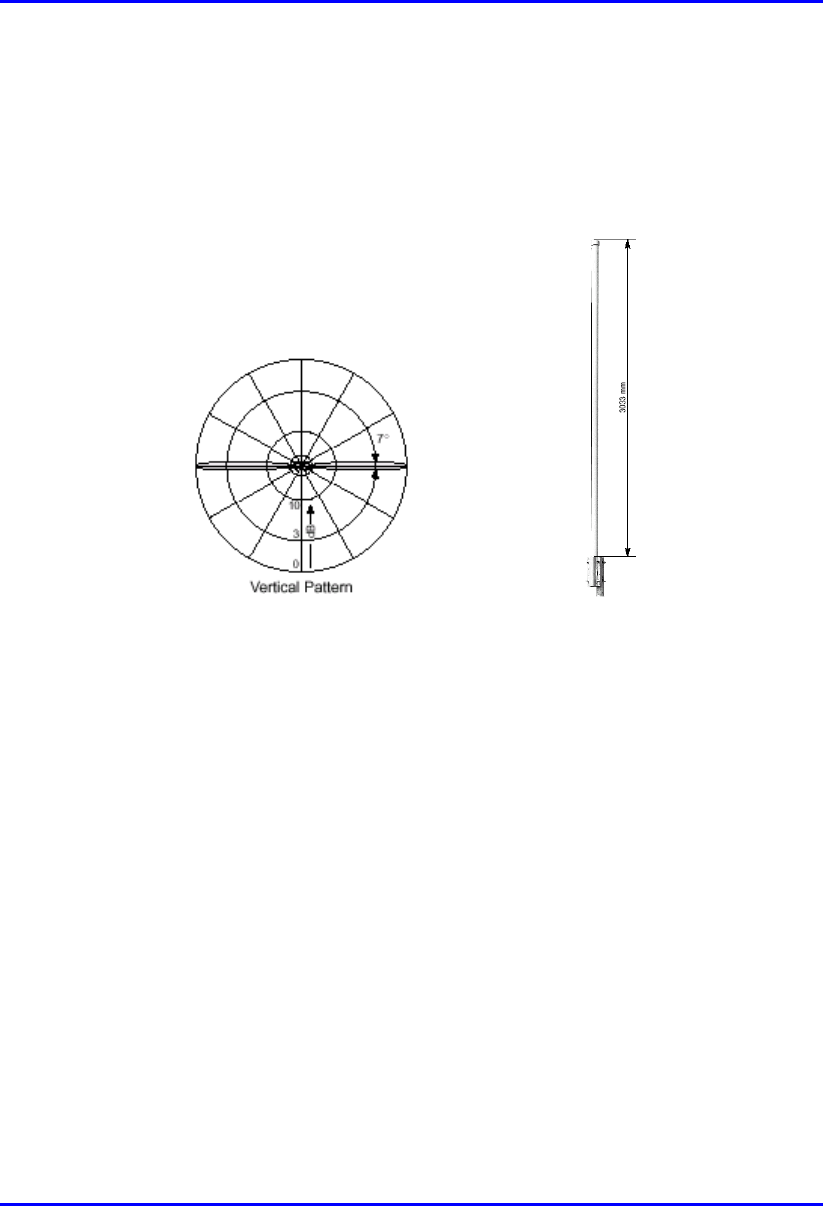
H.1.1.8. Omni-Directional Antenna (11 dBi)
This antenna is designed for best non-line of sight performance with Airspan’s BSR
operating in the 900 MHz band.
Figure H-8: Omni-directional antenna radiation pattern
External Antennas Specifications System Description
H-16 Airspan Networks Inc. 25030311-08
The table below lists the Omni-directional antenna specifications.
Table H-8: Omni-directional antenna specifications
Electrical specifications
Frequency range 870 – 960 MHz
Polarization Vertical
Gain 11 dBi
Impedance 50Ω
VSWR <1.5
Intermodulation IM3
(2 x 43 dBm carrier)
<–150 dBc
Max. Power 500W (at 50 °C ambient temperature)
Mechanical specifications
Model Type 736 347 736 348
Input 7-16 female 7-16 female
Connector position Bottom Top
Weight 8 kg
Radome diameter 51 mm
Wind load 210 N (at 150 km/h)
Max. wind velocity 200 km/h
Packing size 3316 x 148 x 112 mm
Height/width/depth 3033 mm 3022 mm
H.1.2. IDR (at Subscriber Site)
Airspan offers one of the following optional third-party external antennas for the
IDR device operating in the 900 MHz band:
10 dBi Panel antenna
6.5 dBi Panel antenna

System Description External Antennas Specifications
25030311-08 Airspan Networks Inc. H-17
H.1.2.1. 10 dBi Panel
The following table lists the 10-dBi Panel antenna specifications.
Table H-9: 10 dBi Panel antenna specifications
Electrical
Frequency range 902 - 928 MHz
Gain 10 dBi (min)
VSWR 1.5:1 (max)
3 dB Beamwidth
(related to vertical
polarization)
• Azimuth: 65 (typ)
• Elevation: 55 (typ)
Polarization Linear (Vertical or Horizontal)
Side lobes level -18dB (max) @ +/-90
Cross polarization -14dB (max)
F/B ratio -20dB (max)
Input impedance 50 (ohm)
Input power 6W (max)
Lightning protection Non
Mechanical
Dimensions (LxWxD) 305x305x25 mm (max)
Weight 1.5 kg (max)
Connector N-Type Female
Radome Plastic
Base plate Aluminum with chemical conversion coating
Mounting kit MT-120018
Environmental
Test Standard Duration Temperature Notes
Low temperature IEC 68-2-1 72 h -55°C -
High temperature IEC 68-2-2 72 h +71°C -
Temp. cycling IEC 68-2-14 1 h -45°C +70°C 3 Cycles
Vibration IEC 60721-3-4 30 min/axis - Random 4M3

External Antennas Specifications System Description
H-18 Airspan Networks Inc. 25030311-08
Shock mechanical IEC 60721-3-4 - - 4M3
Humidity ETSI EN300-2-4
T4.1E
144 h - 95%
Water tightness IEC 529 - - IP67
Solar radiation ASTM G53 1000 h - -
Flammability UL 94 - - CLASS HB
Salt spray IEC 68-2-11 Ka 500 h - -
Ice and snow - - - 25mm radial
Wind speed survival
Operation
- - - 220 Km/h
160 Km/h
Wind load (survival):
• Front thrust
• Side thrust
- - -
• 26.8 kg
• 2.2 kg
H.1.2.2. 6.5 dBi Panel
The following table lists the 6.5 dBi Panel antenna specifications.
Table H-10: 6.5 dBi Panel antenna specifications
Electrical
Frequency range 902-928 MHz
Gain 6.5 dBi (min)
VSWR 1.5:1 (max)
3 dB Beamwidth
• Azimuth
• Elevation
• 80° (typ)
• 80° (typ)
Polarization Linear (Vertical or Horizontal)
Cross polarization -14dB (max)
F/B ratio -11dB (max)
Input impedance 50 (ohm)
Input power 6W (max)
Lightning protection NON

System Description External Antennas Specifications
25030311-08 Airspan Networks Inc. H-19
Mechanical
Dimensions (LxWxD) 190x190x30 mm (max)
Weight 0.7kg (max)
Connector N-Type Female
Radome Plastic
Base plate Aluminum with chemical conversion coating
Outline drawing RD41245600C
Mounting kit MT-120018/A
Environmental
Test Standard Duration Temperature Notes
Low temperature IEC 68-2-1 72 h -55°C -
High temperature IEC 68-2-2 72 h +71°C -
Temp. cycling IEC 68-2-14 1 h -45°C +70°C 3 Cycles
Vibration IEC 60721-3-4 30 min/axis - Random
4M3
Shock mechanical IEC 60721-3-4 - - 4M3
Humidity ETSI EN300-2-4
T4.1E
144 h - 95%
Water tightness IEC 529 - - IP67
Solar radiation ASTM G53 1000 h - -
Flammability UL 94 - - Class HB
Salt spray IEC 68-2-11 Ka 500 h - -
Ice and snow - - - 25mm radial
Wind speed survival
Operation
- - - 220 Km/h
160 Km/h
Wind load (survival):
• Front thrust
• Side thrust
- - -
• 10 kg
• 1.6 kg

External Antennas Specifications System Description
H-20 Airspan Networks Inc. 25030311-08
H.2. WipLL 700 MHz
The built-in antennas of all WipLL radios, except for WipLL 700 MHz, cover all
frequencies in their respective frequency band. WipLL 700 MHz built-in antenna
covers only Band C (i.e. 710 to 716 MHz, and 740 to 746 MHz) frequency band.
Therefore, Airspan provides an external antenna for WipLL 700, allowing coverage
of the entire 700 MHz band (698 to 746 MHz), including the licensed A and B bands
used in USA.
For most bands, WipLL radios are compatible with a large variety of external
antennas. However, WipLL 700 provides a limited variation of external antennas.
Therefore, for WipLL 700 MHz, the following antennas are provided:
90° panel or omni-directional (for BSR)
14-element yagi antenna (for SPR)
H.2.1. Antenna Specifications
Table H-11 and Table H-12: list the external antenna specifications for BSR and
SPR devices operating in the 700 MHz band, respectively.
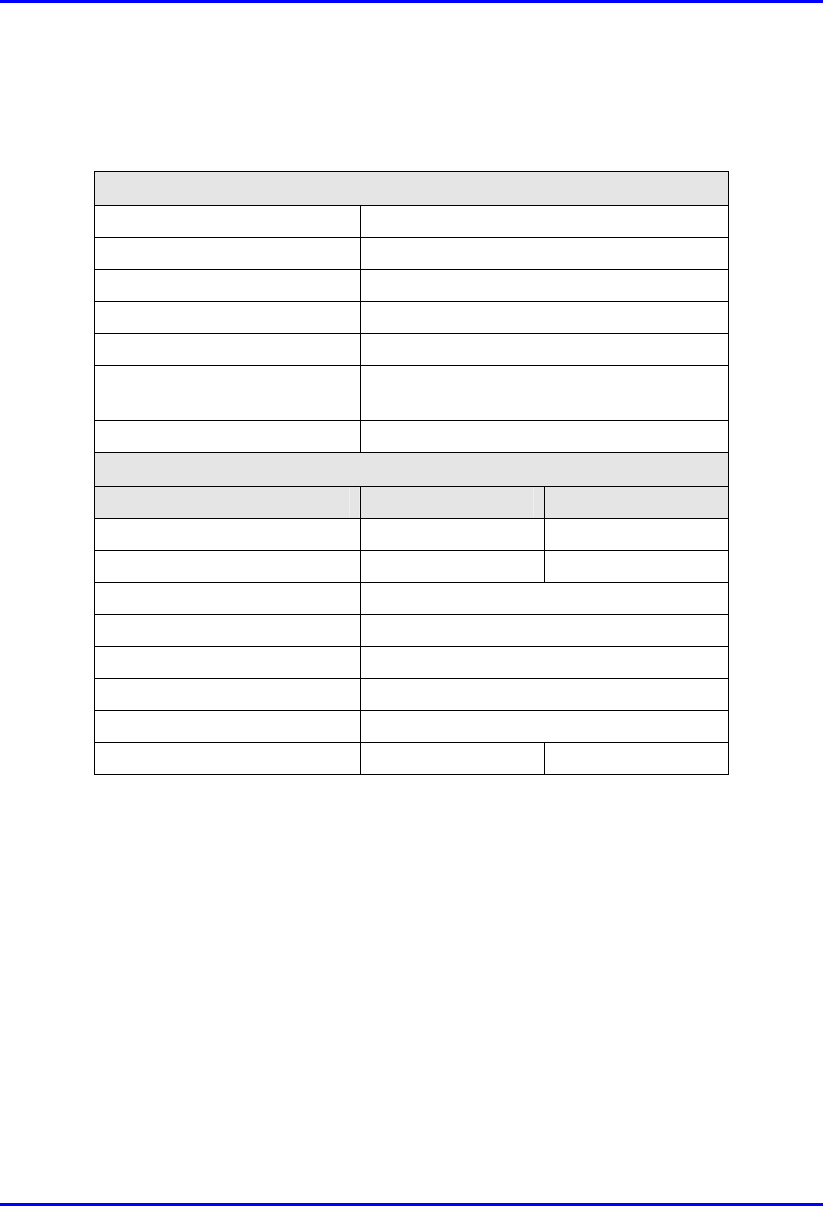
Table H-11: BSR 700 MHz external antennas
External
antenna type
Parameter Value
Frequency Range (MHz) 698 - 746
Gain (dBi) 14
Beam Width H X V (degrees) 90 x 20
Polarization Vertical
VSWR < 1.4
Impedance (ohm) 50
90° panel
Front-to-Back Ratio (dB) > 25
Frequency Range (MHz) 698 - 746
Omnidirectional
Gain (dB) 7.5
System Description External Antennas Specifications
25030311-08 Airspan Networks Inc. H-21
External
antenna type
Parameter Value
Beam Width H X V (degrees) 360 x 20
Polarization Vertical
VSWR 1.5
Impedance (ohm) 50
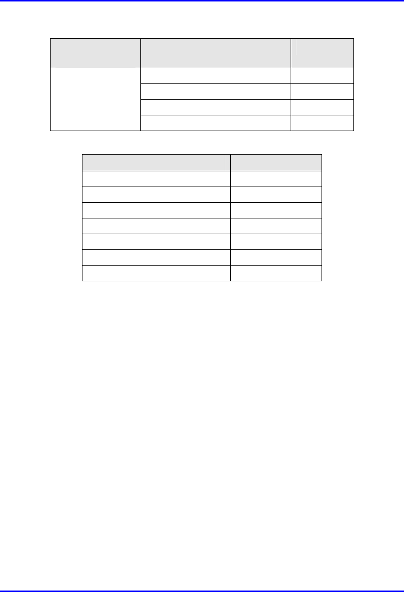
Table H-12:: SPR 700 MHz external yagi antenna
Parameter SPR 700 MHz
Frequency Range (MHz) 698 - 746
Gain (dBi) 13
Beam Width H X V (degrees) 32 x 32
Polarization Vertical/horizontal
VSWR < 1.8
Impedance (ohm) 50
Front-to-Back Ratio (dB) > 15
H.2.2. RF Planning Guidelines for Band C in FCC
Markets
Some operators (e.g., in the USA) have licenses for Band C (710 – 716 MHz and
740 – 746 MHz). When operating in Band C, WipLL 700 allows a maximum of four
BSRs at a Base Station (according to FCC regulations). This is to reduce RF
interference with other radio devices that may be operating in nearby frequencies.
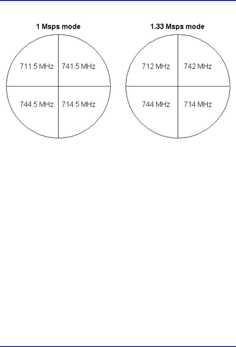
With the 1 Msps mode, the center frequencies are 711.5, 712.5, 713.5, 714.5, 741.5,
742.5, 743.5, and 744.5. Thus, the frequency allocation for four BSRs (i.e., sectors)
is 711.5, 741.5, 714.5, and 744.5.
With the 1.33 Msps mode, the center frequencies are 712, 713, 714, 742, 743, and
744. Thus, the frequency allocation for four BSRs (i.e., sectors) is 712, 742, 714,
and 744.
External Antennas Specifications System Description
H-22 Airspan Networks Inc. 25030311-08
Figure H-9: Frequency allocation in a four-sector Base Station
Radio interference may occur between the BSRs operating in the upper frequency
range (i.e., 742 MHz and 744 MHz) and the lower frequency range (i.e., 712 MHz
and 714 MHz). To overcome this interference, a 1-meter vertical separation is
recommended between the BSRs operating in the upper frequency and the BSRs
operating in the lower frequency.