Airspan Networks AIRSPAN-IDR900 Indoor Data Radio (IDR) User Manual SysDescr 02
Airspan Networks Inc Indoor Data Radio (IDR) SysDescr 02
Contents
- 1. Installation Safety Revised
- 2. Installation Revised
- 3. External Antenna Information
- 4. Internal Antenna Information
Internal Antenna Information

25030311-08 Airspan Networks Inc. 2-1
WipLL Radio Technology -
Physical Layer
The WipLL system provides wireless, local-loop connectivity between the
provider’s IP-based backbone and the subscriber. This radio link is established
between WipLL transceivers located at the Base Station and subscriber sites.
This chapter discusses the following radio frequency (RF) physical layer issues
related to the WipLL system:
Frequency Hopping Spread Spectrum
Modulation
Frequency Bands
Standards Compliance
WipLL RF Antennas
Radio Planning
2
WipLL Radio Technology - Physical Layer System Description
2-2 Airspan Networks Inc. 25030311-08
2.1. Frequency Hopping Spread Spectrum
The WipLL system implements frequency-hopping code division multiple access
(FH-CDMA) spread spectrum modulation for digital signal transmission over the air
between the Base Station and the subscriber site. The WipLL system’s frequency
hopping supports a channel bandwidth of 1 MHz or 1.33 MHz, and channel spacing
of 1 MHz (or 1.75 MHz if operating in the 3.5 GHz band).
Frequency hopping is a basic modulation techniques used in spread spectrum signal
transmission. Spread spectrum enables a signal to be transmitted across a frequency
band that is much wider than the minimum bandwidth required by the information
signal. The transmitter "spreads" the energy, originally concentrated in narrowband,
across a number of frequency band channels on a wider electromagnetic spectrum.
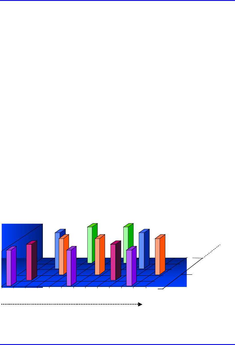
In an FH-CDMA system, a transmitter "hops" between available frequencies
according to a specified algorithm, which can either be random or predefined (see
Figure 2-1). The transmitter operates in synchronization with a receiver, which
remains tuned to the same center frequency as the transmitter. A short burst of data
is transmitted on a narrowband signal. The transmitter then tunes to another
frequency, and transmits again. Therefore, the receiver is capable of hopping its
frequency over a given bandwidth several times a second (20 hops per second in the
WipLL system), transmitting on one frequency for a certain period of time, then
hopping to another frequency and transmitting again. The WipLL system supports a
hopping speed of 50 msec hopping intervals.
TIME
TIME
1
1 2
2 3
3 4
4 5
5 6
6 7
7 88991010 1111 1212
f1f1
f2f2
f3f3
f4f4
f5
f5
Frequency
Each channel
is 1 MHz wide
Figure 2-1: An example of Frequency Hopping Spread Spectrum
System Description WipLL Radio Technology - Physical Layer
25030311-08 Airspan Networks Inc. 2-3
The advantages of implementing FH-CDMA in the WipLL system include the
following:
Frequency Hopping Spread Spectrum (FHSS) is based on interference
avoidance. Narrow band interference that does not meet the SNR blocks only a
few hops, decreasing the throughput only partially.
The required spectrum for an FHSS system is flexible in that it does not have to
be contiguous.
FHSS can coexist with other systems in the same spectrum band.
To intercept transmission, a receiver must “know” the hopping sequence
therefore, FHSS ensures security.
Frequency diversity copes with the frequency selective fading and multipath.
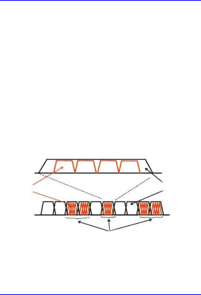
The RF channel obtained by the WipLL operator is divided into n 1-MHz sub-
channels, with center frequencies located at integer multiples of 1 MHz (see Figure
2-2). These sub-channels are organized into a set of orthogonal hopping sequences.
Several methodologies are available for creating these sequences, depending on
available spectrum and local regulations.
Sub-channel RF channel
Assigned band
Figure 2-2: Relationship between “sub-channel”, “RF channel”, and “assigned
channel”
WipLL Radio Technology - Physical Layer System Description
2-4 Airspan Networks Inc. 25030311-08
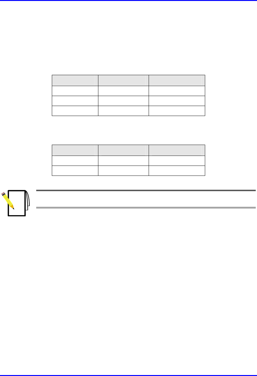
Table 2-1 shows an example of six orthogonal sequences that can be derived from
seven sub-channels.
Table 2-1: Example of six orthogonal FH sequences
Sequence No. Sub-channels (frequencies)
1 0 1 2 3 4 5 6
2 0 2 4 6 1 3 5
3 0 3 6 2 5 1 4
4 0 4 1 5 2 6 3
5 0 5 3 1 6 4 2
6 0 6 5 4 3 2 1
Up to 32 such sequences, each with up to 99 sub-channels can be pre-configured in
the WipLL ROM. An additional 32 sequences can be configured by the WipLL
operator in the RAM to provide further flexibility.
2.2. Modulation
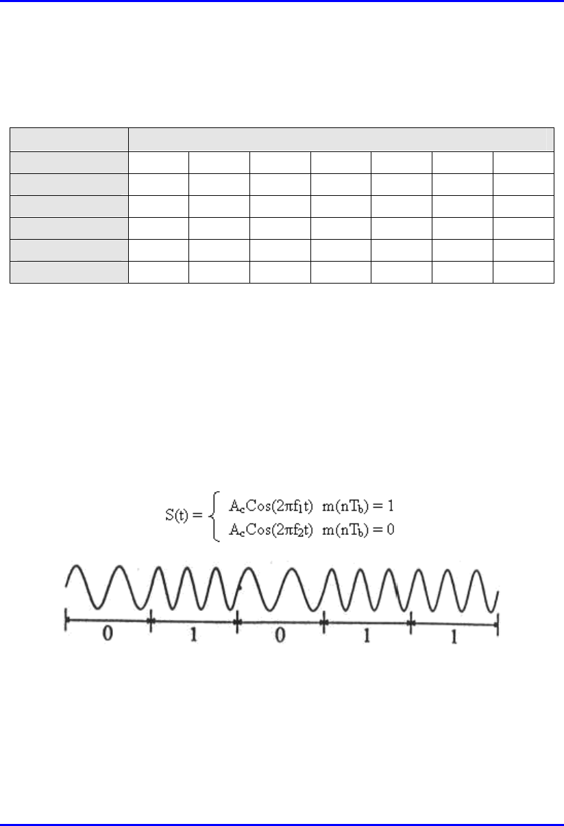
The WipLL system is based on Continuous Phase Frequency Shift Keying (CPFSK)
modulation. Frequency Shift Keying uses m different frequencies for m symbols.
The simplest FSK is binary FSK, where 0 and 1 correspond to different frequencies:
Figure 2-3: Graph displaying different frequencies for 0 and 1 bits
FSK is similar to non-linear analogue FM, but with digital modulation.

System Description WipLL Radio Technology - Physical Layer
25030311-08 Airspan Networks Inc. 2-5
FSK provides the following benefits:
Non-coherent detection is possible - no carrier synchronization is required.
Immunities to non-linearity - the envelope contains no information and,
therefore, can be hard-limited; information is carried by zero crossings:
Can be used with non-linear power amplifiers
Better efficiency
The FSK phase can be discontinuous or continuous, as displayed in Figure 2-4.
Figure 2-4: FSK phase: discontinuous (left wave); continuous (right wave)
Continuous wave is more natural than discontinuous and provides the following
advantages:
Smaller bandwidth (discontinuous wave causes high frequency components)
Operates better when transmission link has non-linearities

WipLL Radio Technology - Physical Layer System Description
2-6 Airspan Networks Inc. 25030311-08
2.3. Frequency Bands
WipLL provides a Wireless Local Loop (WLL) solution in the following frequency
bands:
Licensed bands:
700 MHz (698 – 746 MHz)
2.5 GHz (MMDS)
2.8 GHz (TDD)
3.3 to 3.8 GHz TDD/FDD (50 or 100 MHz duplex separation)
Unlicensed bands:
ISM 900 MHz (902 MHz to 928 MHz)
ISM 2.4 GHz (TDD)
5.8 GHz (TDD)
For details on specific WipLL products, see Appendix B.

System Description WipLL Radio Technology - Physical Layer
25030311-08 Airspan Networks Inc. 2-7
2.4. Standards Compliance
Table 2-2 lists standards to which WipLL complies.
Table 2-2: WipLL standards compliance
Standard Compliance
EMC • 700 MHz: FCC part 27
• 900 MHz: FCC part 15
• 2.4 GHz: ETS 300 826; FCC part 15
• MMDS: FCC part 21
• 3.5 GHz: EN 300 385; EN 300 386-2; ETS 300 132-2
• 5.8 GHz: FCC part 15
Radio • 700 MHz: FCC part 27
• 900 MHz: FCC part 15
• 2.4 GHz: EN 300 328-1; FCC part 15; RSS 139; Telec
• MMDS: FCC part 21
• 3.5 GHz: EN 301 253
• 5.8 GHz: FCC part 15
Safety UL 1950, EN 60950
Environmental ETS 300 019

WipLL Radio Technology - Physical Layer System Description
2-8 Airspan Networks Inc. 25030311-08
2.5. WipLL RF Antennas
WipLL provides a variety of internal antenna types as well as an option for
connecting off-the-shelf, third-party external antennas. Table 2-3 provides a general
description of the WipLL RF antenna parameters.
Table 2-3: WipLL RF antenna specification
Parameter Description
Antenna type • Integral flat-printed antenna: for BSR, PPR, SPR, and IDR devices: No
RF cable is involved for connection between BSR and SPR. The interface
between outdoor radio unit-to-indoor unit (ODU-to-IDU) is by CAT-5
cable.
• Integral narrow-beam antenna: for the BSR device operating in the 3.5
GHz band.
• Integral high-gain antenna: for SPR and PPR devices operating in the
3.5 GHz and 2.4 GHz bands.
Polarization Vertical (Horizontal polarization is optional for SPR at 3.5 GHz)
ETSI compliant EN 302 085, Class CS1 for the BSR, and TS2 for the SPR
Receive diversity Supported in single BSR through dual integral antennas
External third-
party antennas
(optional)
Connects to BSR, PPR, and SPR using an N-type connector. Connects to
IDR using a TNC connector. Provides further flexibility for the WipLL
operator to improve link budget or cost-effectiveness of the Base Station. For
example, an omni-directional antenna for 360º coverage can be implemented
by a single BSR.
For BSRs operating in the 700 MHz or 900 MHz bands, two N-type
connectors are provided for attaching two external third-party antennas for
dual antenna diversity at the WipLL Base Station. When operating in the 700
MHz band, the BSR is supplied with a panel-type antenna; the SPR model
with a yagi-type antenna
Notes: Devices with external antennas do not contain built-in (internal)
antennas.

System Description WipLL Radio Technology - Physical Layer
25030311-08 Airspan Networks Inc. 2-9
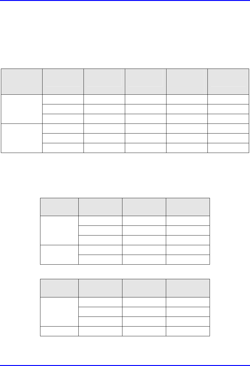
2.5.1. WipLL Internal Antenna Specifications
Table 2-4, Table 2-5, Table 2-6, and Table 2-7 list the internal antenna specifications
of the BSR, PPR, SPR, and IDR devices, respectively.
Table 2-4: BSR (Base Station) antenna specifications
Parameter
BSR
Type
Frequency
range
(MHz)
Gain
(dBi)
Beam
width
H X V
(degrees)
Polarization VSWR Impedance
(ohm)
Front-
to-
back
ratio
(dB)
900
MHz
902 - 928 8 60 x 60 Vertical 1:1.5 50 25
2.4 GHz 2,400 -2,500 11 60 x 25 Vertical 1:1.5 50 25
MMDS 2,500 - 2,690 11 65 x 22 Vertical 1:1.6 50 25
2.8 GHz 2,700 - 2,900 11 60 x 23 Vertical 1:1.5 50 25
3.x GHz 3,300 - 3,800 12 60 x 17 Vertical 1:1.5 50 25
Narrow-
beam
3.x GHz
3,400 -3,700 18 16 x 18 Vertical 1:1.5 50 30
5.8 GHz 5,725 - 5,875 12 60 x 15 Vertical 1:1.5 50 25
Table 2-5: PPR (Base Station) antenna specifications
Parameter
PPR
Type
Frequency
range
(MHz)
Gain
(dBi)
Beam
width H
X V
(degrees)
Polarization VSWR Impedance
(ohm)
Front-
to-
back
ratio
(dB)
2.4
GHz
2,400 -2,500 18 19 x 25 Vertical 1:1.6 50 28
3.x
GHz
3,400 -3,700 18 16 x 18 Vertical 1:1.5 50 30
5.8
GHz
5,725 - 5,875 12 60 x 15 Vertical 1:1.5 50 25

WipLL Radio Technology - Physical Layer System Description
2-10 Airspan Networks Inc. 25030311-08
Table 2-6: SPR (CPE – outdoor unit) antenna specifications
SPR
Type
Freq.
range
(MHz)
Gain
(dBi)
Beam
width
H X V
(deg.
Polari-
zation
VSWR Imped-
ance
(ohm)
Front
-to-
back
ratio
(dB)
700 MHz 710 - 716
&
740- 746
8 60 x 60 Vertical 1:1.6 50 20
900 MHz 902 - 928 8 60 x 60 Vertical 1:1.9 50 23
2.4 GHz 2,400 -
2,500
15 24 x 33 Vertical 1:1.6 50 28
High-gain
2.4 GHz
2,400 -
2,500
18 19 x 25 Vertical 1:1.6 50 28
MMDS 2,500 -
2,690
15 21 x 29 Vertical 1:1.6 50 25
2.8 GHz 2,700 -
2,900
15 21 x 30 Vertical 1:1.6 50 25
3.5 GHz 3,400 -
3,600
15 18 x 28 Vertical/
Horizontal
1:1.6 50 25
High-gain
3.5 GHz
3,400 -
3,600
18 16 x 18 Vertical 1:1.6 50 25
5.8 GHz 5,725 -
5,875
16 21 X 12 Vertical 1:1.6 50 25
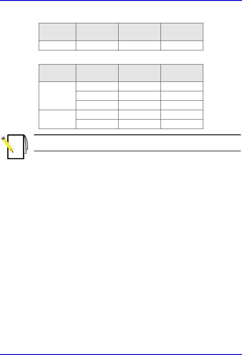
Notes:
1) The SPR 700 MHz and 900 MHz models have larger dimensions than the
standard SPR models. Their dimensions are the same as that for the BSR.
2) The SPR 3.5 GHz and SPR 2.4 GHz models are available in large and
standard (smaller) dimensions (chassis). The dimensions (i.e., large or small)
affect the antenna gain.
3) The 700 MHz internal antenna covers only 710 - 716 MHz and 740 - 746
MHz (i.e. Band C). To cover the entire band of 698 – 746 MHz, an external
antenna is used (see Section 2.5.2tbd”).

System Description WipLL Radio Technology - Physical Layer
25030311-08 Airspan Networks Inc. 2-11
Table 2-7: IDR (CPE - indoor unit) antenna specifications
IDR
Type
Freq.
range
(MHz)
Gain
(dBi)
Beam
width
H X V
(deg.)
Polarization VSWR Impedance
(ohm)
Front-
to-
back
ratio
(dB)
900
MHz
902 - 928 8 67 x 93 Vertical 1:1.9 50 -17
2.4 GHz 2,400 to
2,500
10 65 x 32 Vertical 1:1.6 50 25
3.5 GHz 3,400 to
3,600
10 65 x 32 Vertical 1:1.6 50 25
2.5.2. WipLL External Antennas
WipLL provides options to attach external antennas when operating in the 700 and
900 MHz bands.
2.5.2.1. 900 MHz
The WipLL BSR and IDR devices operating in the 900 MHz band, provide N-type
receptacles for connecting external antennas. The BSR provides two N-type
receptacles (for antenna diversity), and the IDR provides one TNC-type receptacle.
This document lists the specifications of these external antennas intended for the
BSR and IDR devices.
2.5.2.1.1. BSR External Antennas
Airspan provides the following external antennas for BSR devices operating in the
900 MHz band:
Sector antenna
Omnidirectional antenna
WipLL Radio Technology - Physical Layer System Description
2-12 Airspan Networks Inc. 25030311-08
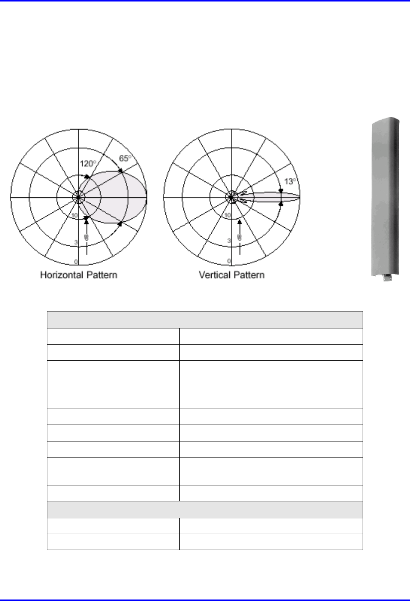
2.5.2.2. Sector Antenna
This antenna is designed for best non-line of sight performance with Airspan’s BSR
operating in the 900 MHz band. Advanced features include: high gain and
mechanical downtilt.
Electrical specifications
Frequency range 870 –960 MHz
Polarization Vertical
Gain 15.5 dBi
Half-power beam width • H-plane:65°
• E-plane:13°
Front-to-back ratio >25 dB
Impedance 50 .
VSWR <1.3
Intermodulation IM3
(2 x 43 dBm carrier)
<–150 dBc
Max.power 500 W (at 50 °C ambient temperature)
Mechanical specifications
Input 7-16 female
Connector position Bottom
System Description WipLL Radio Technology - Physical Layer
25030311-08 Airspan Networks Inc. 2-13
Weight 6 kg
Wind load • Frontal: 220 N (at 150 km/h)
• Lateral: 140 N (at 150 km/h)
• Rearside: 490 N (at 150 km/h)
Max.wind velocity 200 km/h
Packing size 1422 x 272 x 160 mm
Height/width/depth 1294 /258 /103 mm
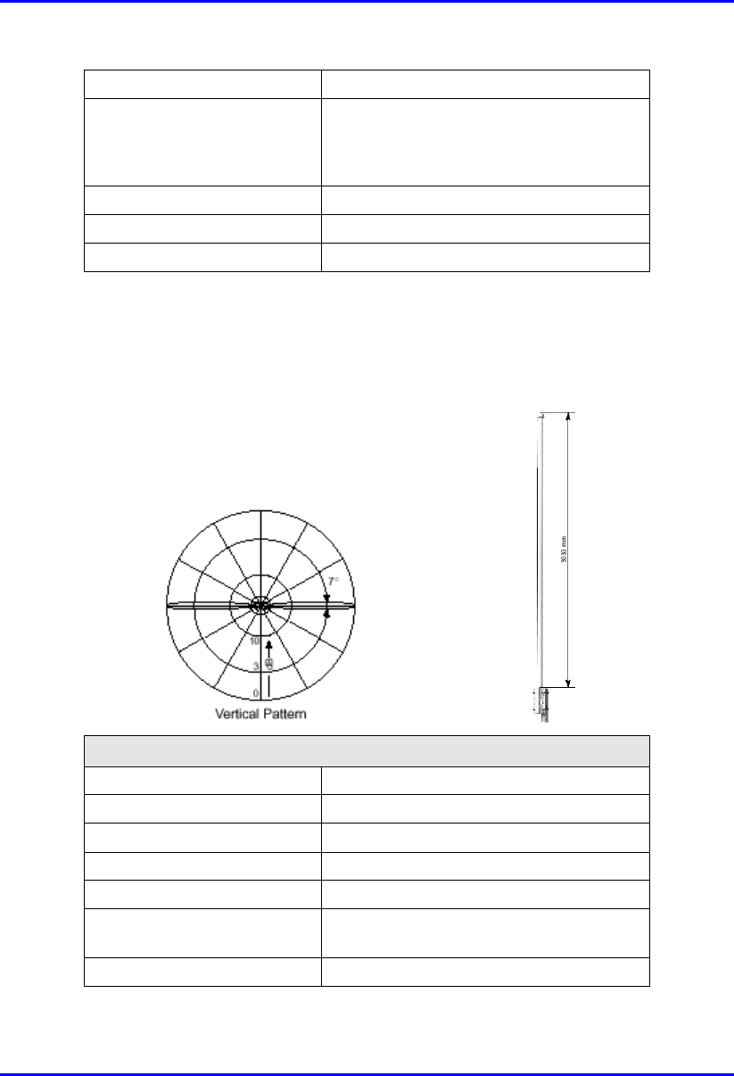
2.5.2.2.1. Omnidirectional Antenna
This antenna is designed for best non-line of sight performance with Airspan’s BSR
operating in the 900 MHz band.
Electrical specifications
Frequency range 870 – 960 MHz
Polarization Vertical
Gain 11 dBi
Impedance 50Ω
VSWR <1.5
Intermodulation IM3
(2 x 43 dBm carrier)
<–150 dBc
Max. power 500W (at 50 °C ambient temperature)

WipLL Radio Technology - Physical Layer System Description
2-14 Airspan Networks Inc. 25030311-08
Mechanical specifications
Model Type 736 347 736 348
Input 7-16 female 7-16 female
Connector position Bottom Top
Weight 8 kg
Radome diameter 51 mm
Wind load 210 N (at 150 km/h)
Max.wind velocity 200 km/h
Packing size 3316 x 148 x 112 mm
Height/width/depth 3033 mm 3022 mm
2.5.2.3. IDR External Antennas
Airspan provides one of the following external antennas for the IDR device
operating in the 900 MHz band:
10 dBi Panel antenna
6.5 dBi Panel antenna

System Description WipLL Radio Technology - Physical Layer
25030311-08 Airspan Networks Inc. 2-15
2.5.2.3.1. 10 dBi Panel
Electrical
Frequency range 902 - 928 MHz
Gain 10 dBi (min)
VSWR 1.5:1 (max)
3 dB Beamwidth
(related to vertical
polarization)
• Azimuth: 65 (typ)
• Elevation: 55 (typ)
Polarization Linear (Vertical or Horizontal)
Sidelobes level -18dB (max) @ +/-90
Cross polarization -14dB (max)
F/B ratio -20dB (max)
Input impedance 50 (ohm)
Input power 6W (max)
Lightning protection Non
Mechanical
Dimensions (LxWxD) 305x305x25 mm (max)
Weight 1.5 kg (max)
Connector N-Type Female
Radome Plastic
Base plate Aluminum with chemical conversion coating
Mounting kit MT-120018
Environmental
Test Standard Duration Temperture Notes
Low temperature IEC 68-2-1 72 h -55°C -
High temperature IEC 68-2-2 72 h +71°C -
Temp. cycling IEC 68-2-14 1 h -45°C +70°C 3 Cycles
Vibration IEC 60721-3-4 30 min/axis - Random 4M3
Shock mechanical IEC 60721-3-4 - - 4M3
Humidity ETSI EN300-2-4
T4.1E
144 h - 95%
Water tightness IEC 529 - - IP67

WipLL Radio Technology - Physical Layer System Description
2-16 Airspan Networks Inc. 25030311-08
Solar radiation ASTM G53 1000 h - -
Flammability UL 94 - - CLASS HB
Salt spray IEC 68-2-11 Ka 500 h - -
Ice and snow - - - 25mm radial
Wind speed survival
Operation
- - - 220 Km/h
160 Km/h
Wind load (survival):
• Front thrust
• Side thrust
- - -
• 26.8 kg
• 2.2 kg
2.5.2.3.2. 6.5 dBi Panel
Electrical
Frequency range 902-928 MHz
Gain 6.5 dBi (min)
VSWR 1.5:1 (max)
3 dB Beamwidth
• Azimuth
• Elevation
• 80° (typ)
• 80° (typ)
polarization Linear (Vertical or Horizontal)
Cross polarization -14dB (max)
F/B ratio -11dB (max)
Input impedance 50 (ohm)
Input power 6W (max)
Lightning protection NON
Mechanical
Dimensions (LxWxD) 190x190x30 mm (max)
Weight 0.7kg (max)
Connector N-Type Female
Radome Plastic
Base plate Aluminum with chemical conversion coating
Outline drawing RD41245600C
Mounting kit MT-120018/A

System Description WipLL Radio Technology - Physical Layer
25030311-08 Airspan Networks Inc. 2-17
Environmental
Test Standard Duration Temperture Notes
Low temperature IEC 68-2-1 72 h -55°C -
High temperature IEC 68-2-2 72 h +71°C -
Temp. cycling IEC 68-2-14 1 h -45°C +70°C 3 Cycles
Vibration IEC 60721-3-4 30 min/axis - Random
4M3
Shock mechanical IEC 60721-3-4 - - 4M3
Humidity ETSI EN300-2-4
T4.1E
144 h - 95%
Water tightness IEC 529 - - IP67
Solar radiation ASTM G53 1000 h - -
Flammability UL 94 - - Class HB
Salt spray IEC 68-2-11 Ka 500 h - -
Ice and snow - - - 25mm radial
Wind speed survival
Operation
- - - 220 Km/h
160 Km/h
Wind load (survival):
• Front thrust
• Side thrust
- - -
• 10 kg
• 1.6 kg
2.5.2.4. Considerations for WipLL 700
For most of the frequency bands, WipLL products provide a variation of models
consisting of internal and external antennas. The internal antennas of all WipLL
products, except for WipLL 700, cover all frequency bands.
WipLL 700’s internal antenna covers only Band C (i.e., 710 to 716 MHz, and 740 to
746 MHz) frequency band. Therefore, for WipLL 700, Airspan provides an external
antenna, allowing coverage in the entire 700 MHz band (698 to 746 MHz), including
the licensed A and B bands used in USA.

WipLL Radio Technology - Physical Layer System Description
2-18 Airspan Networks Inc. 25030311-08
2.5.2.5. External Antennas
For most bands, WipLL products allow connection of a large variety of external
antennas. However, WipLL 700 provides a limited variation of external antennas,
including, amongst others, the following:
90° panel or omnidirectional (for BSR)
14-element yagi antenna (for SPR)
These external antennas can be supplied by Airspan. The external antennas connect
to the WipLL devices by an N-type connector.
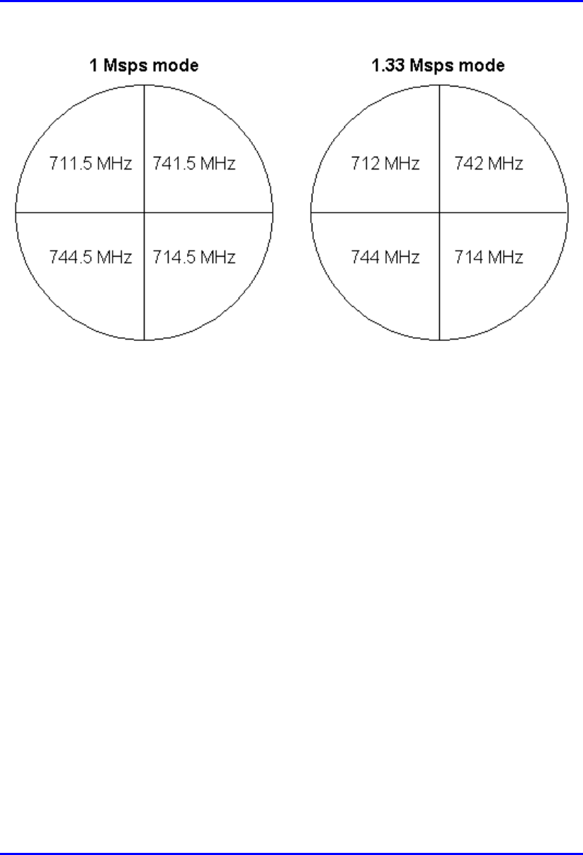
2.5.2.6. RF Planning Guidelines for Band C in FCC Market
Some operators (e.g., in the USA) have licenses for Band C (710 – 716 MHz and
740 – 746 MHz). When operating in Band C, WipLL 700 allows a maximum of four
BSRs at a Base Station (according to FCC regulations). This is to reduce RF
interference with other radio devices that may be operating in nearby frequencies.
With the 1 Msps mode, the center frequencies are 711.5, 712.5, 713.5, 714.5, 741.5,
742.5, 743.5, and 744.5. Thus, the frequency allocation for four BSRs (i.e., sectors)
is 711.5, 741.5, 714.5, and 744.5.
With the 1.33 Msps mode, the center frequencies are 712, 713, 714, 742, 743, and
744. Thus, the frequency allocation for four BSRs (i.e., sectors) is 712, 742, 714,
and 744.
System Description WipLL Radio Technology - Physical Layer
25030311-08 Airspan Networks Inc. 2-19
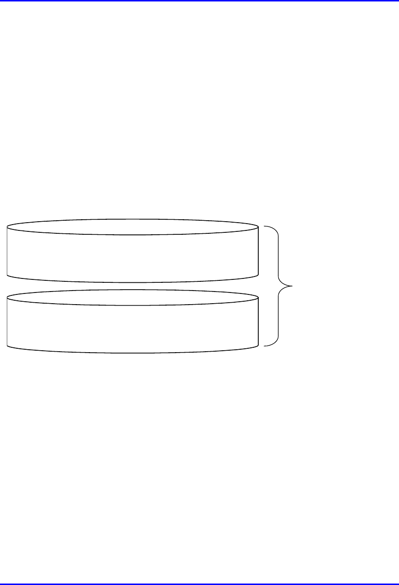
Figure 2-5: Frequency allocation in a four-sector Base Station
Radio interference may occur between the BSRs operating in the upper frequency
range (i.e., 742 MHz and 744 MHz) and the lower frequency range (i.e., 712 MHz
and 714 MHz). To overcome this interference, a 1-meter vertical separation is
recommended between the BSRs operating in the upper frequency and the BSRs
operating in the lower frequency.

WipLL Radio Technology - Physical Layer System Description
2-20 Airspan Networks Inc. 25030311-08
2.5.2.7. Specifications
Table 2-4 and Table 2-6 list the external antenna specifications for BSR and SPR
devices operating in the 700 MHz band.
Table 2-8: BSR 700 MHz external antennas
External
antenna type
Parameter Value
Frequency Range (MHz) 698 - 746
Gain (dBi) 14
Beam Width H X V (degrees) 90 x 20
Polarization Vertical
VSWR < 1.4
Impedance (ohm) 50
90° panel
Front-to-Back Ratio (dB) > 25
Frequency Range (MHz) 698 - 746
Gain (dB) 7.5
Beam Width H X V (degrees) 360 x 20
Polarization Vertical
VSWR 1.5
Omnidirectional
Impedance (ohm) 50
Table 2-9: SPR 700 MHz external yagi antenna
Parameter SPR 700 MHz
Frequency Range (MHz) 698 - 746
Gain (dBi) 13
Beam Width H X V (degrees) 32 x 32
Polarization Vertical/horizontal
VSWR < 1.8
Impedance (ohm) 50
Front-to-Back Ratio (dB) > 15

System Description WipLL Radio Technology - Physical Layer
25030311-08 Airspan Networks Inc. 2-21
2.6. Radio Planning
WipLL radio planning can be divided into the following areas:
Main technical parameters
Coverage analysis
Interference analysis: FDD vs. TDD
Frequency allocation: Synchronized vs. Unsynchronized operation
Capacity considerations
Selecting appropriate mode of operation
Radio Planning software tool

WipLL Radio Technology - Physical Layer System Description
2-22 Airspan Networks Inc. 25030311-08
2.6.1. Main Technical Parameters
The main technical parameters required for RF planning for WipLL are summarized
in Table 2-10.
Table 2-10: Radio specifications
Parameter Value
Radio Technology FH-CDMA
Multiple Access Method Proprietary Adaptive TDMA protocol (Preemptive
Polling Multiple Access – PPMA)
Output Power 27 dBm for all models, except for the following:
• WipLL 700: 32 dBm
• WipLL 900: 30 dBm (but when operating in
countries complying with FCC, max. is 23
dBm)
Sub-Channel Spacing 1 MHz or 1.75 MHz (1.75 MHz is possible only
for devices operating in the 3.5 GHz band)
Symbols per second (Msps) Two modes are supported:
• 1 Msps, or
• 1.33 Msps
Sub-Channel bandwidth (measured at 20 dB
attenuation point)
1 MHz or 1.33 MHz, depending on the selected
mode
Modulation Multilevel (2, 4, or 8) CPFSK1
Receiver Sensitivity (BER 1E-6 at 2/4/8
FSK)
-90/ -83/ -75 dBm
SNR Thresholds (BER 1E-6 at 2/4/8 FSK) 12/ 20/ 28 dB
Interference Rejection Factor for 1.33 Msps
mode (1 Msps mode):
• ± 1 MHz
• ± 2 MHz
• ± 3 MHz
• 5 dB (7 dB)
• 30 dB (40 dB)
• 52 dB (53 dB)
1 The intermediate 4-FSK modulation is not supported when 1.33 Msps mode is
selected

System Description WipLL Radio Technology - Physical Layer
25030311-08 Airspan Networks Inc. 2-23
Parameter Value
• ± 4 MHz
• ± 5 MHz
• 58 dB (60 dB)
• 63 dB (64 dB)
Receiver Noise Figure 10 dB
2.6.2. System Coverage
System coverage includes the following:
Line of sight (LOS)
Link Budget
2.6.2.1. Line of Sight
Usually, WipLL requires the existence of a line of sight (LOS) between the base
station transmitter and the subscriber’s receiver (near line of sight [NLOS] may be
possible to a limited extent for ranges of a few hundred meters). Therefore, the
availability of LOS (clear first Fresnel Zone) should be estimated during CPE
installation or preferably during network planning. Recommended propagation
models used in coverage analysis are based on free-space propagation with
compensation for ground and irregular terrain reflections and diffraction. Specific
propagation model names vary between different software tools. The model should
also include a certain level of fade margin, as discussed in the next section.

WipLL Radio Technology - Physical Layer System Description
2-24 Airspan Networks Inc. 25030311-08
2.6.2.2. Link Budget
The coverage analysis of WipLL includes the analysis of the power balance between
the transmitter and the receiver, threshold considerations, margins, reserves, and
certain statistics of the system. Therefore, the lead-in reception level is measured by
the following equation:
Rx = Tx – LossTx + AntGainTx – PathLoss + AntGainRx – LossRx
Where,
Rx = Reception level in dBm
Tx = Transmitter power in dBm (27 dBm in the WipLL system)
LossTx = Transmitter losses in dB (0 dB in the WipLL system)
LossRx = Terminal receiver losses in dB (0 dB in the WipLL system)
AntGainTx = Transmitter antenna gain
AntGainRx = Receiver antenna gain in dBi (decibels referenced to isotropic
radiator)
PathLoss = Propagation loss in dB
Note: Both the base station and the subscriber site can serve as transmitter o
r
receiver. For downlink budget, the transmitter is the base station and the
receiver is the subscriber; and vice versa for the uplink budget.

System Description WipLL Radio Technology - Physical Layer
25030311-08 Airspan Networks Inc. 2-25
2.6.2.2.1. Propagation loss
Propagation is the dispersal of the signal into space as it leaves the antenna. The loss
of this propagation depends on the signal path between the transmitter and the
receiver. Obstructions in the signal path such as trees and buildings can cause signal
degradation. Several models simulate signal attenuation along this path.
Propagation loss should incorporate fading margins to compensate different
phenomenon such as multipath shadowing and climatic behavior of the waves.
Based on this, the parameter path loss can be represented by
PathLoss = L + Fade Margin.
Free Space model:
Free space propagation loss is valid where the first Fresnel Zone is clear. In this
case, free space propagation loss is given by the following equation:
LFS = 32.44 + 20logd[km] + 20logf[MHz]
Fade Margin:
Fade margin further introduces fading factor to the propagation loss to cover the
different signal fading and shadow effects, as well as the degradation caused by
interferences. The fading factor depends on the time availability parameter
defined by the operator, and should be calculated according to the ITU 530
model for 99.9% availability.
For simplicity purposes, the ITU model can be replaced by a 10 dB Flat fade
margin as a rough estimation.
Rainfall:
Radio signals are attenuated by moisture in the atmosphere. The level of
attenuation varies with carrier frequency, the quantity of rainfall, and the
distance from the transmitter to the receiver. The variation of attenuation
with frequency is particularly strong and highly non-linear. At 3 GHz, the
highest attenuation is about 0.06 dB/Km; for a typical WLL path of, for
example, 6 Km, the attenuation is only 0.36 dB. Therefore, for the purpose of
link budget, we can assume that the impact of rainfall is negligible.
WipLL Radio Technology - Physical Layer System Description
2-26 Airspan Networks Inc. 25030311-08
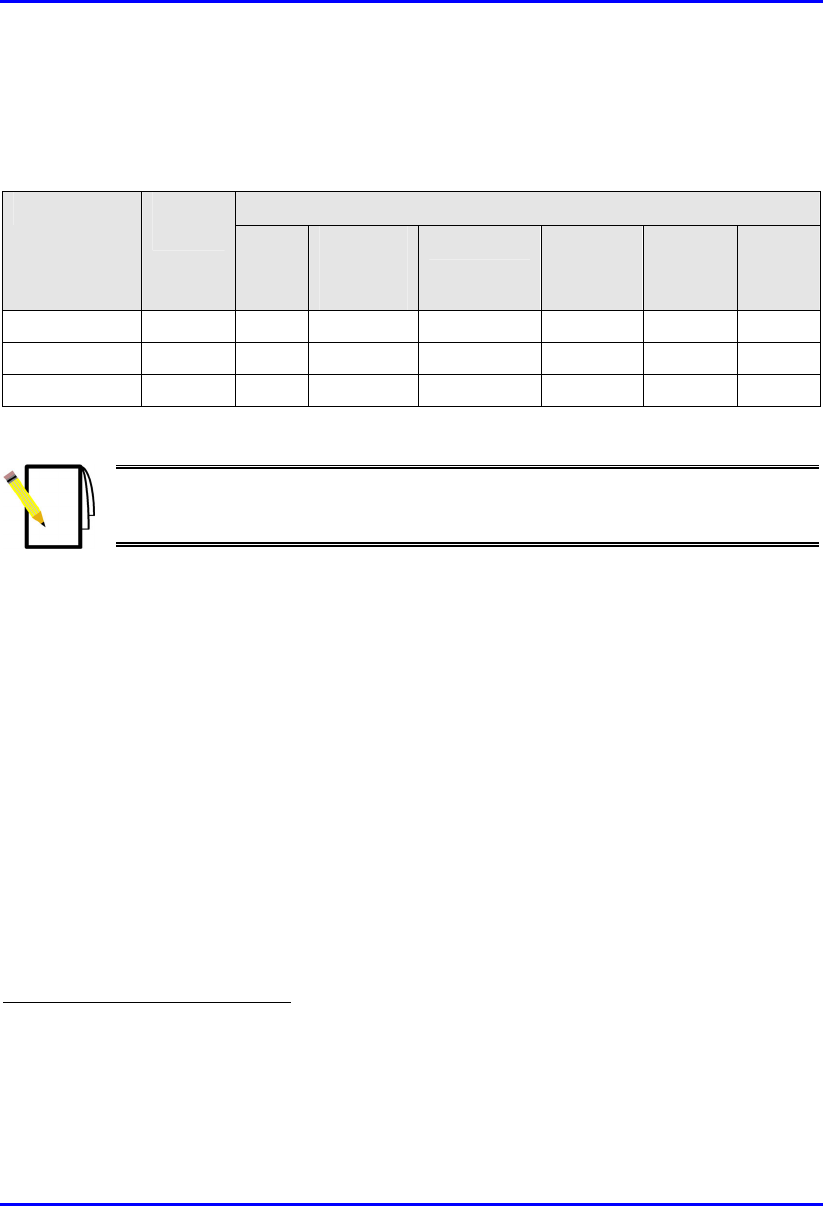
2.6.2.2.2. Link Budget Results
Based on the previous formulas mentioned in the above sections, the following link
budget results can be obtained for 99.9% availability:
Range (in km) Modulation Rate
(Mbps) 2.4
GHz2
MMDS
(2.5
GHz)
3.5 GHz 5.8
GHz
900
MHz
700
MHz
8 FSK 3 or 4 8 8 7 6 8 15
4 FSK 2 11 11 10 8 11 22
2 FSK 1 or 1.33 14 14 13 11 15 28
Note: Link budget is calculated for the standard integrated WipLL antennas.
Where required, the range can be increased by the implementation of external
antennas.
2.6.3. Interference Analysis
Interference analysis should be based on parameters defined in Section 2.6.1, “Main
Technical Parameters” to determine the downlink and uplink carrier-to-interference
ratio (C/I). The C/I is a key factor in determining the supported modulation for each
link. Thresholds for C/I for the different modulations are mentioned in Section 2.6.1,
“Main Technical Parameters”.
Interference analysis depends on the duplex scheme implemented in the system.
Since WipLL supports both FDD and TDD, different considerations should be
applied.
2 Although the transmitter is capable of transmitting 27 dBm, in most cases the EiRP
in the ISM band is limited by local regulations. For example, ETSI limits the EiRP
to 20 dBm, FCC to 36 dBm, and TELEC to 27 dBm. The link budget calculated
here assumes no limit.
System Description WipLL Radio Technology - Physical Layer
25030311-08 Airspan Networks Inc. 2-27
2.6.3.1. FDD vs. TDD
Frequency Division Duplex (FDD) interference analysis is relatively simple. The
frequency separation between downlink and uplink (50 to 100 MHz) enables
Airspan to conduct downlink and uplink interference analysis independently.
However, in Time Division Duplex (TDD), since Tx and Rx are not synchronized,
cross-link interference, for example, between a transmitting BSR and an adjacent
receiving BSR, may result. It is expected that these interferences will be dominant in
the TDD mode.
The major consequence of this are the different limitations imposed on frequency
separation between adjacent BSRs:
FDD: 2 MHz
TDD: 4 MHz
The required separation is a function of the isolation between co-located antennas.
The 4-MHz separation is based on 60 dB isolation. Based on this, a simple
frequency allocation for a stand-alone cell is presented in Figure 2-6.
Frequency Allocation
Single Cell (FDD)
11
9
7
5
3
1
Frequency Allocation
Single Cell (TDD)
Figure 2-6: Frequency Allocation for a stand-alone cell: FDD (left) vs. TDD (right)

WipLL Radio Technology - Physical Layer System Description
2-28 Airspan Networks Inc. 25030311-08
2.6.4. Frequency Allocation
Frequency allocation includes the following issues:
Synchronized vs. Unsynchronized operation
Frequency Reuse
Frequency Allocation template
2.6.4.1. Synchronized vs. Unsynchronized Operation
The frequency allocation scheme in WipLL depends on the mode of operation.
Three main options exist:
Unsynchronized Frequency Hopping
Synchronized Frequency Hopping
Fix Sub-Channel Assignment
2.6.4.1.1. Unsynchronized Frequency Hopping
A scenario may exist whereby the operator does not want to synchronize base
stations due to cost or regulatory issues. For example, the FCC prohibits
synchronization between base stations when operating in the unlicensed band. In
such a scenario, the BSRs (and SPRs) are assigned pseudo-random frequency tables,
and, therefore, collisions between transceivers are possible, resulting in some level
of retransmissions. However, implementing orthogonal frequency tables (hopping
sequences) reduces collisions.
In this mode of operation, the available set of sub-channels, which must include a
prime number of sub-channels, is organized into several different hopping sequences
that are orthogonal to each other. Each BSR in the coverage area is assigned a
different sequence (until there is a need to start reusing the tables). The degradation
level in performance due to collisions will be a random number, depending on the
length of the frequency tables (the number of available sub-channels).
System Description WipLL Radio Technology - Physical Layer
25030311-08 Airspan Networks Inc. 2-29
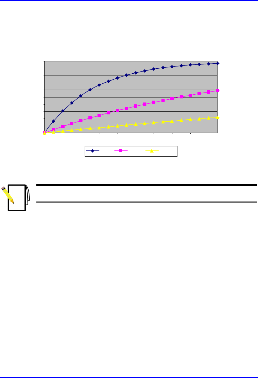
Figure 2-7 displays a graph depicting the hit or blocking probability as a function of
number of interferers for different table lengths (7, 23, and 79).
0
0.1
0.2
0.3
0.4
0.5
0.6
0.7
0.8
0.9
1
1 3 5 7 9 1113151719
N = 7 N = 23 N = 79
Figure 2-7: Hit probability as a function of active interferers
Note: The probability of collisions with 20 interferers and 79 sub-channels is
only 20%.
2.6.4.1.2. Synchronized Frequency Hopping
In most scenarios, the operator synchronizes between WipLL base-stations located
in the same coverage area. This option provides the best control over intra-system
interferences.
In this mode of operation, the available set of sub-channels is arranged in a single
hopping sequence, common to all transceivers (BSRs and SPRs) in the coverage
area. Since the table ID is identical to all radios, the only parameter that needs to be
assigned is the phase, that is, the starting point within the sequence.
By selecting the sequence appropriately, the relative frequency separation between
the transceivers remains constant over time, so that interference analysis is quite
similar to any Frequency Division Multiple Access (FDMA) system.
WipLL Radio Technology - Physical Layer System Description
2-30 Airspan Networks Inc. 25030311-08
2.6.4.1.3. Fix Sub-Channel Assignment
In some scenarios—mainly licensed bands in which available spectrum is limited—
it is possible to create a set of “hopping” tables, each based on a single sub-channel.
Using this approach, the hopping nature of the system is actually disabled, so that
synchronization is not required. The trade-off of this approach is loss of frequency
diversity, discussed previously as a means to overcome frequency-selective fading.
Interference analysis in this mode is identical to any FDMA system.
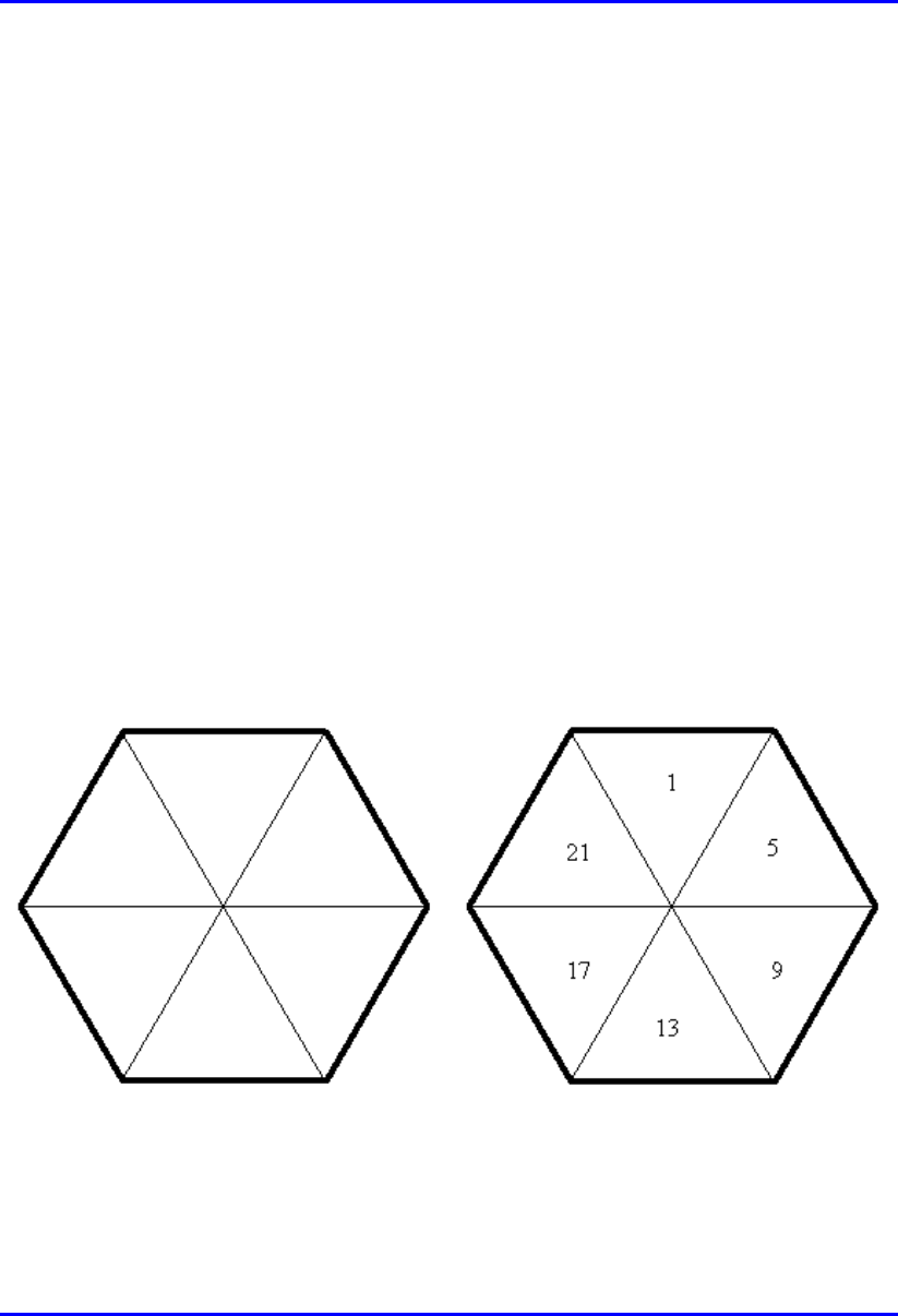
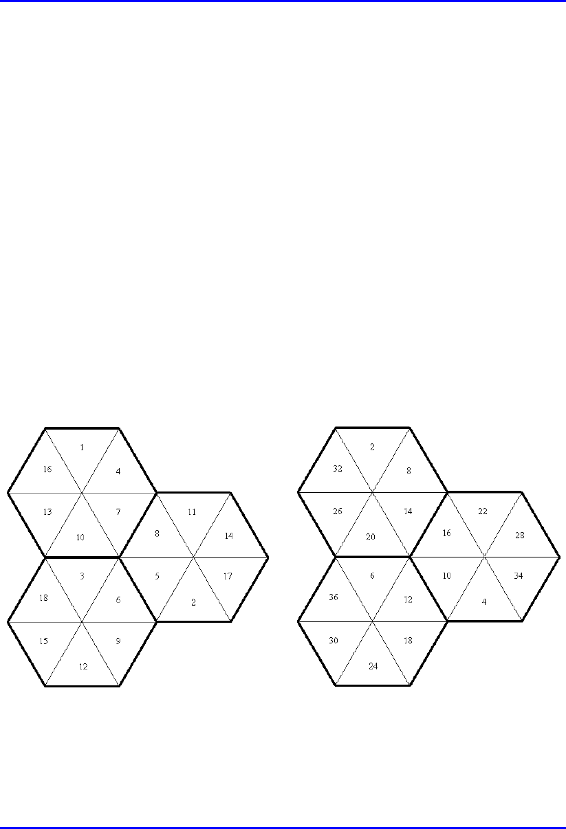
2.6.4.2. Frequency Allocation
Figure 2-8 presents frequency allocation for three adjacent cells for the FDD and
TDD schemes. This frequency allocation is relevant only for synchronized
frequency hopping or fix sub-channel assignment options. For the unsynchronized
frequency hopping option described previously, orthogonal frequency tables are
assigned instead of specific sub-channels (or phases). As described in Section 2.6.3,
“Interference Analysis”, 60-dB isolation between co-located BSRs is assumed for
the TDD allocation.
Figure 2-8: Frequency Allocation FDD (left) and TDD (right)
System Description WipLL Radio Technology - Physical Layer
25030311-08 Airspan Networks Inc. 2-31
2.6.5. Capacity Considerations
This section provides high-level guidelines for evaluating WipLL capacity. This
capacity relates to the number of subscribers supported by a single BSR according to
a certain service mix. The methodology presented here provides a simplified
approach for evaluating WipLL capacity capabilities. It can be used as an initial
estimation; however, it cannot replace a more accurate capacity analysis performed
by an RF planning team.
2.6.5.1. General
The general concept for determining the number of subscribers per BSR is presented
in Figure 2-9.
Aggregate CIR / Over Subscription Factor
Voice Calls * Call BW
BSR Limit (Kbps)
Figure 2-9: Determining number of subscribers per BSR
The BSR limit is 4 Mbps; therefore, the total voice and data bandwidth must be
lower or equal to 4 Mbps.
The number of voice calls should be derived from Erlang B tables according to
voice traffic per subscriber (in erlangs), and expected blocking probability (typically
1%) parameters. The VoIP bandwidth depends on the specific codec that will be
used. Typical values are specified in the next section.
The data portion of the aggregated traffic is based on the sum of the committed
information rate (CIR) for all subscribers assigned to the BSR, divided by the
appropriate over subscription rate.
WipLL Radio Technology - Physical Layer System Description
2-32 Airspan Networks Inc. 25030311-08
Since voice and data services differ by their packet size and their sensitivity to delay,
their protocol efficiency can be substantially different. Therefore, when calculating
bandwidth for different applications, the gross bandwidth should be used, which
takes into account the protocol efficiency.
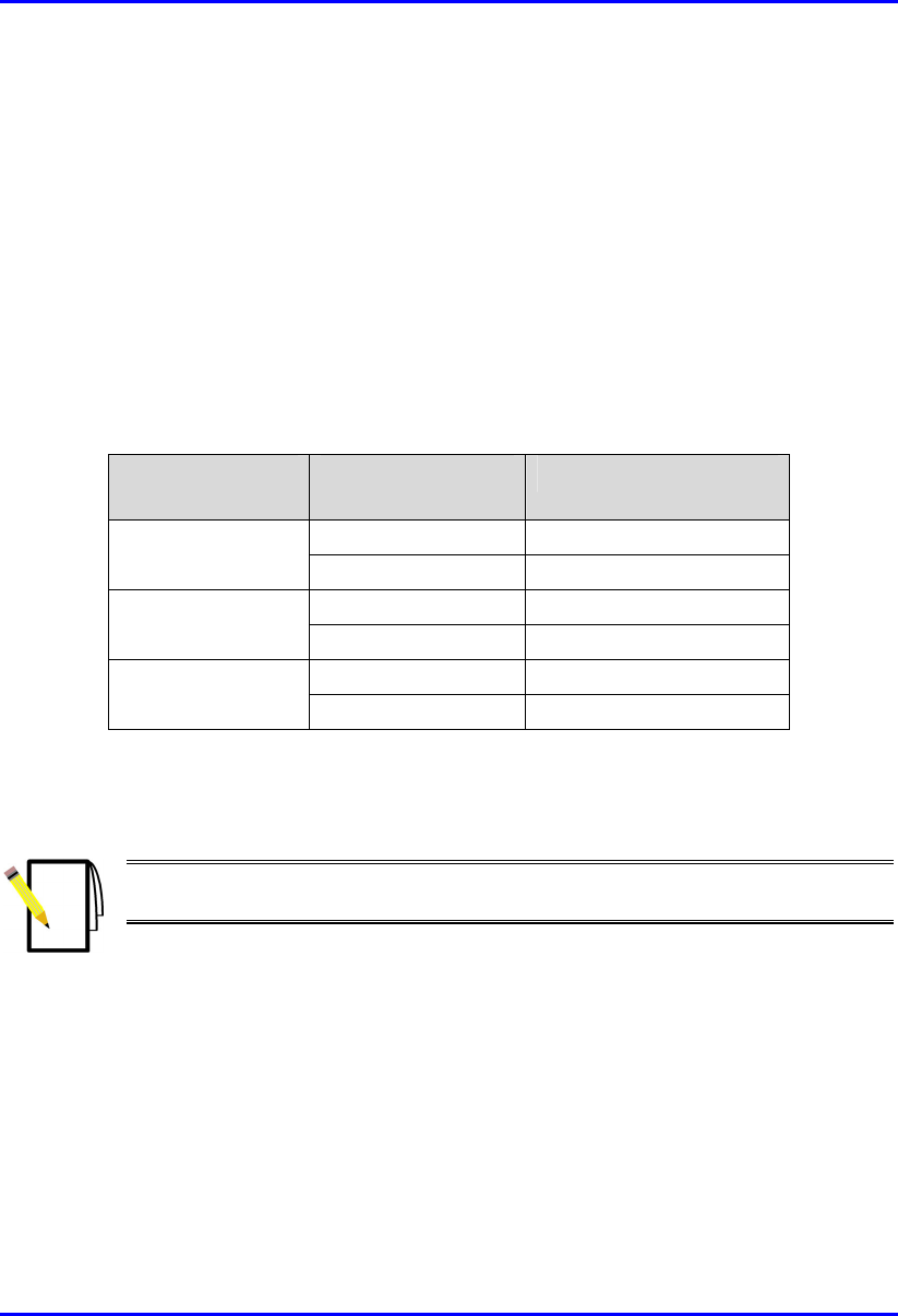
2.6.5.2. VoIP Bandwidth and Simultaneous Calls
The VoIP bandwidth and the number of supported simultaneous calls are a function
of the selected codec and the sample interval. Assuming a 4 Mbps gross rate, the
following numbers can be used:
Table 2-11: VoIP bandwidth (Kbps) for 4 Mbps gross rate
Codec Sample Interval
(msec)
Simultaneous Calls
20 10
G.711 (64 Kbps) 40 15
20 14
G.729 (8 Kbps) 40 28
30 22
G.723.1 (5.3 Kbps) 60 42
If silence suppression is used, a factor of 65% should be applied on the call
bandwidth.
Note: The selection of the appropriate codec should be based on a balance
between the occupied bandwidth and the voice quality.
2.6.5.3. Data Bandwidth
It is assumed that packet size for data applications is relatively large (about 1,500
bytes), resulting in a protocol efficiency of 80%. Taking this into account, the sum
of all data bandwidth should be divided by 80% to obtain the bandwidth over the air.

System Description WipLL Radio Technology - Physical Layer
25030311-08 Airspan Networks Inc. 2-33
2.6.5.4. Calculation Example
This example assumes that the required services are based on voice traffic of 100
merlangs per subscriber and a CIR of 256 Kbps. In addition, in this example, a 1%
blocking is expected for voice calls, and 1:10 over subscription is expected for data.
The number of subscribers that can be supported by a single BSR (N) is equal to
Kbps
KbpsN
CodecCallsSim
Kbps
GostrafficCalls 000,4
%80
256%10
)(_
000,4
),( ≤
⋅
⋅
+⋅
Assume that N = 40. Therefore, the aggregate voice traffic is equal to 4 erlangs.
Using Erlang B tables with 1% blocking, 10 voice channels (calls) are required. For
G.729 with 40 msec sample interval and silence suppression, the total capacity set
for voice is obtained by 10*143 Kbps*65% = 930 Kbps. The total capacity set for
data is obtained by 40*256 Kbps*10%/80% = 1,280 Kbps. This implies that more
subscribers can be supported, since the aggregated capacity (2,210 Kbps) is lower
than the 4 Mbps limit. If N (BSRs) increases, the limit of 4 Mbps will be reached for
N = 80. (The process of finding N can be simplified by using an electronic
spreadsheet).
2.6.6. Selecting an Appropriate Operation Mode
WipLL enables the operator the flexibility to choose between several modes of
operation according to the operator’s needs. One of the optional modes relates to the
symbol rate of the modem. This section presents the main issues that should be
considered when selecting an operation mode when deploying the WipLL system.
2.6.6.1. WipLL Multiple Modes
WipLL offers the capability to select between two operating modes in terms of
symbol rate. The modem can operate in either 1 Mega symbols per second (Msps) or
1.33 Msps. The operating mode is software selectable for each BSR. The differences
between the modes of operation are related to the bit rate and the channel bandwidth.
WipLL Radio Technology - Physical Layer System Description
2-34 Airspan Networks Inc. 25030311-08
2.6.6.1.1. Bit Rate
The 1 Msps mode supports three levels of modulation, as presented in Table 2-12.
Table 2-12: WipLL bit rate at 1 Msps
Modulation Bit/Symbol Bit rate (Mbps)
8-level FSK 3 3
4-level FSK 2 2
2-level FSK 1 1
The 1.33 Msps mode supports two levels of modulation according to Table 2-13.
Table 2-13: WipLL bit rate at 1.33 Msps
Modulation Bit/Symbol Bit rate (Mbps)
8-level FSK 3 4
2-level FSK 1 1.33
Note: The differences in sensitivity and SNR values between the two modes
are negligible.
2.6.6.1.2. Channel Bandwidth
The 1.33 Msps is based on shorter symbols, with the trade-off of a wider channel
bandwidth. The 20 dB attenuation point for the 1 Msps mode and the 1.33 Msps
mode is 1 MHz and 1.33 MHz, respectively.

System Description WipLL Radio Technology - Physical Layer
25030311-08 Airspan Networks Inc. 2-35
2.6.6.2. System Range Considerations
System range depends on the maximum output power of the system. Different
approaches exist, depending on region and frequency band.
2.6.6.2.1. Unlicensed Bands
FCC part 15 (paragraph 247) differentiates between three types of systems:
Digital modulated
Frequency hopping
Hybrid
Limitations on Tx (transmit) power and EIRP differ on this basis. Table 2-14
summarizes the limitations for the different WipLL products.
Table 2-14: Tx power and EIRP limitations for WipLL products
Frequency
band
Mode Tx power EIRP System type
1 Msps 15 dBm 36 dBm Hybrid
900 MHz
1.33 Msps 18 dBm 36 dBm Hybrid
1 Msps -- 36 dBm Frequency
hopping
2.4 GHz
1.33 Msps -- 27 dBm Frequency
hopping
1 Msps -- 36 dBm Frequency
hopping
5.8 GHz
1.33 Msps 18 dBm 36 dBm Hybrid
Note: For WipLL 900, the BSR’s external antenna must have a minimum cable loss
of 2.5 dB to comply with FCC’s EIRP limit of 36 dBm. EIRP is calculated as:
Max. Power Output + Antenna Gain + Cable Loss ≤ 36 dBm (EIRP)
WipLL Radio Technology - Physical Layer System Description
2-36 Airspan Networks Inc. 25030311-08
The table below lists examples of cable loss per cable for maximum antenna gains,
based on the formula above. Note that the EIRP is either equal to or less than 36
dBm.
Table 2-15: Example of cable loss per cable for maximum antenna gains
Cable type Cable
length (ft)
Tx power
(dBm)
Cable loss
(dB)
Max.
antenna
gain (dBi)
Max. EIRP
(dBm)
10 18 0.6 18.6 36
30 18.9 1.5
18.6 36
BELDEN -
9913
100 21.8 4.4 18.6 36
10 19.3 1.9
18.6 36
30 22.6 5.2
18.6 36
BELDEN -
89907
100 23 16.3
18.6 25.3
Table 2-16, Table 2-17, and Table 2-18 present system ranges (in kilometers) for the
different frequency bands (900 MHz, 2.4 GHz, and 5.8 GHz, respectively) and
modes of operation (i.e., 1 Msps and 1.33 Msps).
Table 2-16: WipLL range at FCC limits for 900 MHz
Mode Modulation Rate
(Mbps)
Range
(Km)
8 FSK 3 4
4 FSK 2 10
1 Msps
2 FSK 1 24
8 FSK 4 6
1.33 Msps 2 FSK 1.33 35
Table 2-17: WipLL range at FCC limits for 2.4 GHz
Mode Modulation Rate
(Mbps)
Range
(Km)
8 FSK 3 4
4 FSK 2 10
1 Msps
2 FSK 1 22
1.33 Msps 8 FSK 4 1
System Description WipLL Radio Technology - Physical Layer
25030311-08 Airspan Networks Inc. 2-37
Mode Modulation Rate
(Mbps)
Range
(Km)
2 FSK 1.33 8
Table 2-18: WipLL range at FCC limits for 5.8 GHz
Mode Modulation Rate
(Mbps)
Range
(Km)
8 FSK 3 2
4 FSK 2 5
1 Msps
2 FSK 1 10
8 FSK 4 1
1.33 Msps 2 FSK 1.33 8
Note: Link budget is calculated for the uplink assuming free space
propagation standard integrated antenna and 10 dB fade margin.
As shown in the tables, the system range for the 1 Msps mode is approximately three
times higher than for the 1.33 Msps mode due to the 9 dB differences in Tx
(transmit) power.
2.6.6.2.2. Licensed Bands (3.5 GHz)
No distinction exists between the two modes in terms of system range.
2.6.6.3. Interference Rejection
Two types of interference should be considered:
Intra-system interference: caused by multiple WipLL transmitters
Inter-system interference: caused by external transmitters, mainly in the
unlicensed bands

WipLL Radio Technology - Physical Layer System Description
2-38 Airspan Networks Inc. 25030311-08
2.6.6.3.1. Intra-system Interference
As mentioned previously, 1.33 Msps mode is achieved by using wider channel
bandwidth. This results in a higher bit rate at the expense of increasing adjacent
channel interference. This difference can become critical mainly for licensed bands
in which the available spectrum might be very limited. It is beyond the scope of this
document to provide specific rules regarding the preferred mode as a function of the
available spectrum. This is due to the fact that such analysis depends on many
parameters such as the cell layout and the topography of the coverage area.
However, it should be evaluated during radio planning.

System Description WipLL Radio Technology - Physical Layer
25030311-08 Airspan Networks Inc. 2-39
2.6.6.3.2. Inter-system Interference
The immunity of the WipLL system to external interference is due to its spread
spectrum system. Exposure to external interference is highest when operating in the
unlicensed band. Both FCC and ETSI set limits on the spreading level that is
required by a frequency hopping spread spectrum system.
ETSI:
According to EN 300 328, FHSS modulation must use at least 20 well-defined,
non-overlapping channels separated by the channel bandwidth as measured at 20
dB below peak power.
Since WipLL’s carriers must be located at integer multiples of megahertz
(MHz), the above statement limits the channel spacing to 1 MHz for the 1 Msps
mode, and 2 MHz for the 1.33 Msps mode. This limits the number of possible
hops in the WipLL system when operating under ETSI regulations to between 20
and 80 for the 1 Msps mode, and between 20 and 40 for the 1.33 Msps mode.
FCC:
Part 15 of the FCC sets the same requirement for non-overlapping channels.
For frequency hopping systems operating in the 902 MHz to 928 MHz band with
a channel bandwidth greater than 250 KHz, the system shall use at least 25
hopping frequencies.
For frequency hopping systems operating in the 5725 MHz to 5850 MHz band,
the system shall use at least 75 hopping frequencies.
For frequency hopping systems operating in the 2400 MHz to 2483.5 MHz band,
the system shall use at least 15 non-overlapping channels.
In general, since the number of different hops is substantially lower, the capability of
WipLL to overcome interferences is reduced. In practice, ETSI allows the operator
the flexibility not to use the entire spectrum, in case, for example, a constant
interference is identified in a portion of the spectrum. This makes the problem much
less critical than in the FCC case, where the entire spectrum must be used.

WipLL Radio Technology - Physical Layer System Description
2-40 Airspan Networks Inc. 25030311-08
2.6.6.4. System Capacity
The modulation for each link in the WipLL system is adaptively determined
according to the signal strength and the BER. When evaluating system capacity, it
should be taken into account that the intermediate 4-FSK modulation is not
supported when operating at 1.33 Msps.
Assume a WipLL deployment where subscribers are located at various distances
from the base stations. In general, three coverage circles can be expected around
each base station:
Inner circle—supporting 8-level FSK
Intermediate circle—supporting 4-level FSK
Outer circle—supporting 2-level FSK
Let pi, pm, and po represent the percentages of subscribers located at the inner,
intermediate, and outer coverage circles, respectively. The average capacity of the
system (without taking into account advanced features like fairness) for each of the
possible modes can be given by the following formulas:
()
33.14][
123][
33.1
1
⋅++⋅=
⋅
+
⋅
+
⋅
=
omiMsps
omiMsps
pppMbpsCapacity
pppMbpsCapacity
Radio planning can provide estimations for pi, pm, and po so that the WipLL operator
can determine which option provides the highest system capacity.
2.6.6.5. Conclusion
The 1.33 Msps mode provides superior bit rate, but at the expense of a possible
reduction in radio coverage (FCC), and/or increase in interference. A certain amount
of radio planning is required to determine the preferable mode to maximize the
overall capacity of the access network.

System Description WipLL Radio Technology - Physical Layer
25030311-08 Airspan Networks Inc. 2-41
2.6.7. Radio Planning Software Tool
To design an optimal fixed wireless broadband network, the operator requires an RF
design tool that includes features of a geographic information system (GIS) module,
a propagation prediction module, and a fixed wireless module.
The GIS module should map data that contain or can be assigned geographic
coordinates, for example, terrain elevation, land-use classification, site locations,
design area boundaries, roads, and highways.
The propagation prediction module should provide RF propagation analysis and
predictions. This module must support features that allow the propagation model to
be calibrated using drive test measurements.
The fixed wireless module should support directional CPE antennas for coverage,
capacity and interference analysis in LOS and NLOS conditions, and adaptive
modulation.
2.6.7.1. Geographic Information Systems Database
To enable detailed and accurate propagation prediction, terrain information must be
supplemented by a Geographic Information Systems (GIS) database. Clutter
databases are typically based on Satellite or Aerial photography, depending on the
resolution of the planning. Clutter databases should include Definition of Clutter
Types and Clutter Height relative to the underlying DEM.
The resolution of data varies depending on the environment at which the planning is
targeted. Airspan recommends the following:
Rural: 10 to30 meters
Urban: 5 to 20 meters
The specific format of the database depends on the planning tool. The planning
software provider or user’s manual should be consulted to obtain the appropriate
format.

WipLL Radio Technology - Physical Layer System Description
2-42 Airspan Networks Inc. 25030311-08
This page is intentionally left blank.