Airspan Networks AIRSPAN-IDR900 Indoor Data Radio (IDR) User Manual SysDescr 02
Airspan Networks Inc Indoor Data Radio (IDR) SysDescr 02
Contents
- 1. Installation Safety Revised
- 2. Installation Revised
- 3. External Antenna Information
- 4. Internal Antenna Information
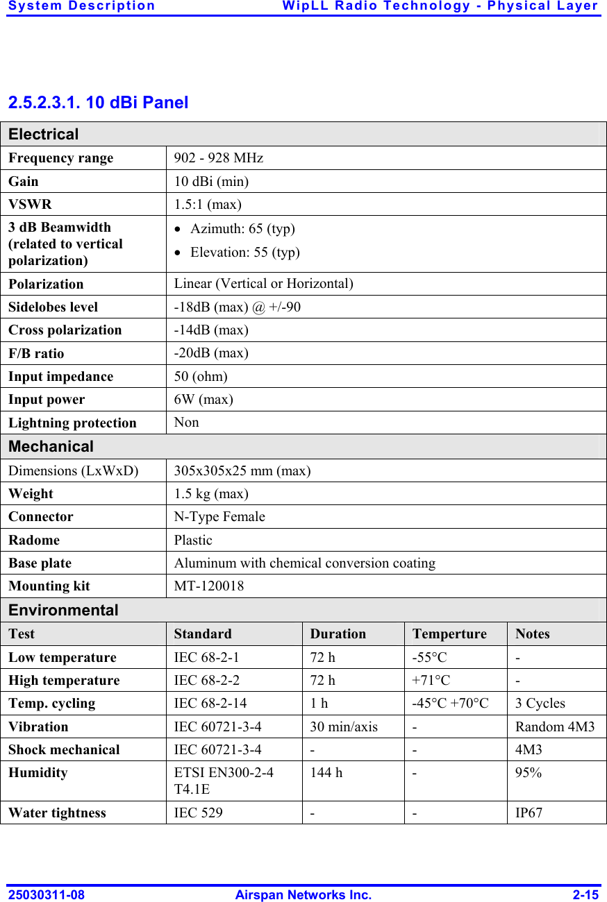
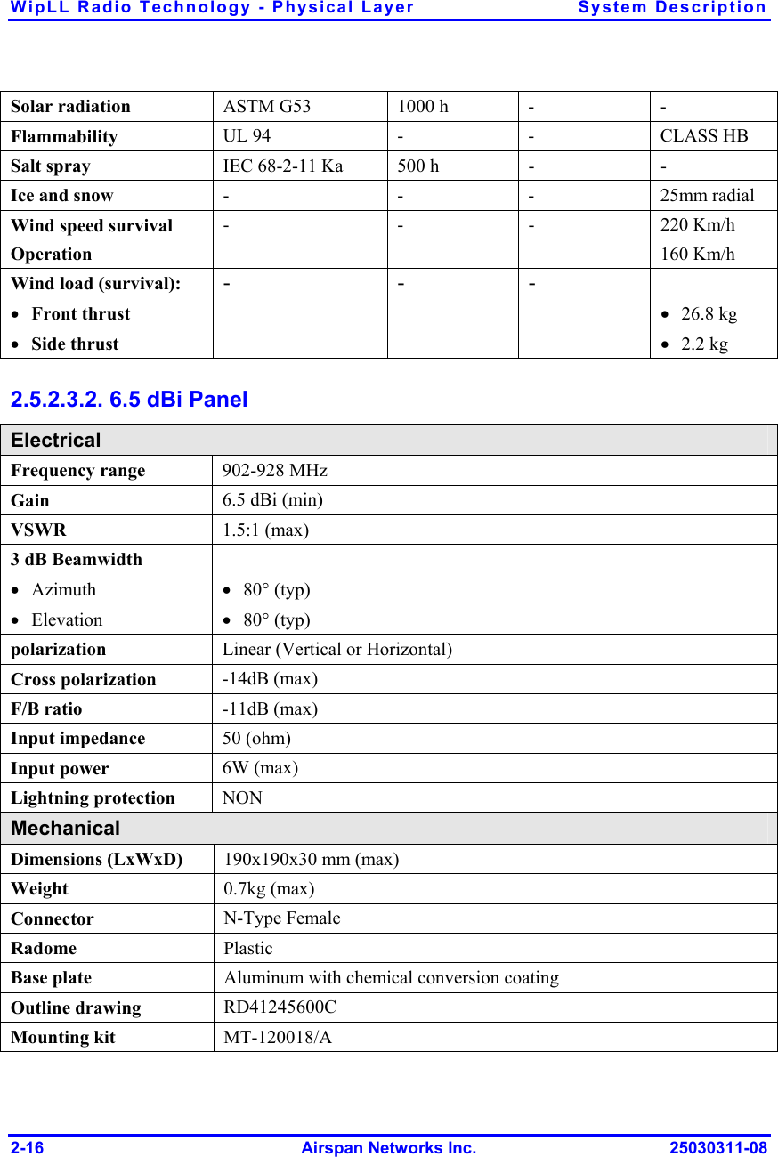
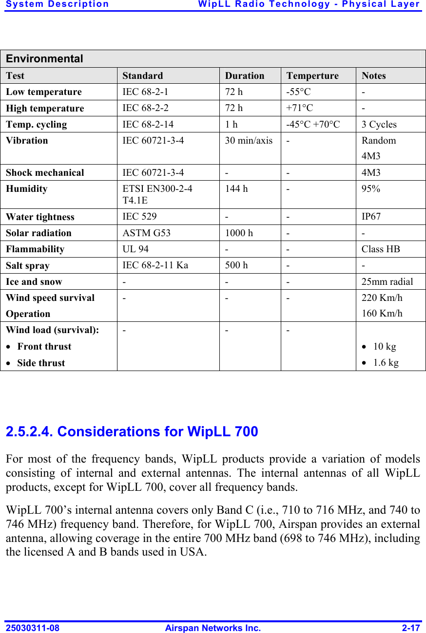
Internal Antenna Information
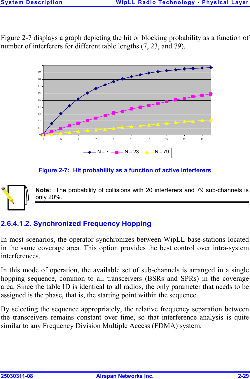
![System Description WipLL Radio Technology - Physical Layer 25030311-08 Airspan Networks Inc. 2-23 Parameter Value • ± 4 MHz • ± 5 MHz • 58 dB (60 dB) • 63 dB (64 dB) Receiver Noise Figure 10 dB 2.6.2. System Coverage System coverage includes the following: Line of sight (LOS) Link Budget 2.6.2.1. Line of Sight Usually, WipLL requires the existence of a line of sight (LOS) between the base station transmitter and the subscriber’s receiver (near line of sight [NLOS] may be possible to a limited extent for ranges of a few hundred meters). Therefore, the availability of LOS (clear first Fresnel Zone) should be estimated during CPE installation or preferably during network planning. Recommended propagation models used in coverage analysis are based on free-space propagation with compensation for ground and irregular terrain reflections and diffraction. Specific propagation model names vary between different software tools. The model should also include a certain level of fade margin, as discussed in the next section.](https://usermanual.wiki/Airspan-Networks/AIRSPAN-IDR900.Internal-Antenna-Information/User-Guide-428032-Page-23.png)
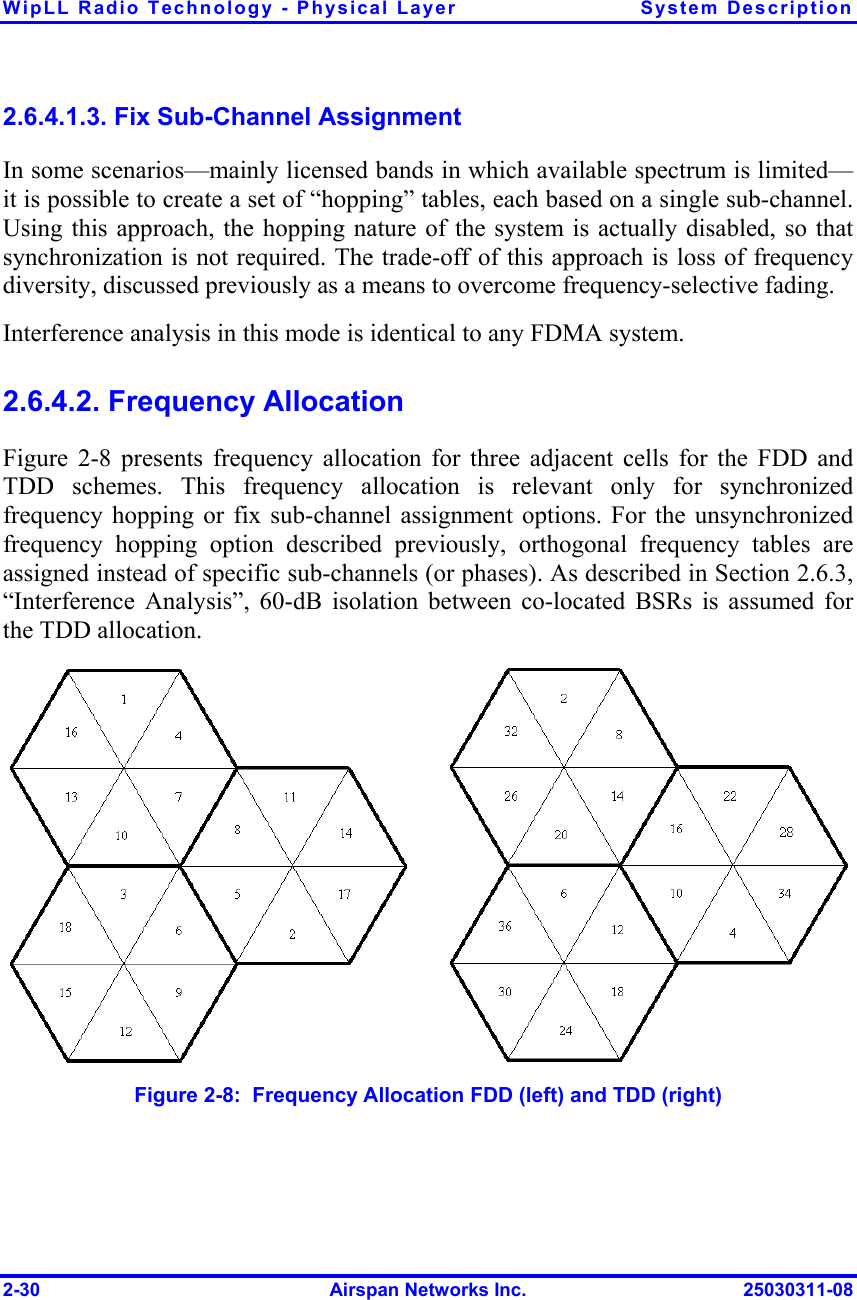
![System Description WipLL Radio Technology - Physical Layer 25030311-08 Airspan Networks Inc. 2-25 2.6.2.2.1. Propagation loss Propagation is the dispersal of the signal into space as it leaves the antenna. The loss of this propagation depends on the signal path between the transmitter and the receiver. Obstructions in the signal path such as trees and buildings can cause signal degradation. Several models simulate signal attenuation along this path. Propagation loss should incorporate fading margins to compensate different phenomenon such as multipath shadowing and climatic behavior of the waves. Based on this, the parameter path loss can be represented by PathLoss = L + Fade Margin. Free Space model: Free space propagation loss is valid where the first Fresnel Zone is clear. In this case, free space propagation loss is given by the following equation: LFS = 32.44 + 20logd[km] + 20logf[MHz] Fade Margin: Fade margin further introduces fading factor to the propagation loss to cover the different signal fading and shadow effects, as well as the degradation caused by interferences. The fading factor depends on the time availability parameter defined by the operator, and should be calculated according to the ITU 530 model for 99.9% availability. For simplicity purposes, the ITU model can be replaced by a 10 dB Flat fade margin as a rough estimation. Rainfall: Radio signals are attenuated by moisture in the atmosphere. The level of attenuation varies with carrier frequency, the quantity of rainfall, and the distance from the transmitter to the receiver. The variation of attenuation with frequency is particularly strong and highly non-linear. At 3 GHz, the highest attenuation is about 0.06 dB/Km; for a typical WLL path of, for example, 6 Km, the attenuation is only 0.36 dB. Therefore, for the purpose of link budget, we can assume that the impact of rainfall is negligible.](https://usermanual.wiki/Airspan-Networks/AIRSPAN-IDR900.Internal-Antenna-Information/User-Guide-428032-Page-25.png)
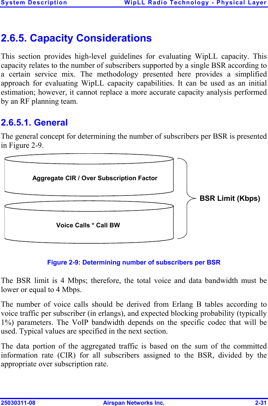
![WipLL Radio Technology - Physical Layer System Description 2-40 Airspan Networks Inc. 25030311-08 2.6.6.4. System Capacity The modulation for each link in the WipLL system is adaptively determined according to the signal strength and the BER. When evaluating system capacity, it should be taken into account that the intermediate 4-FSK modulation is not supported when operating at 1.33 Msps. Assume a WipLL deployment where subscribers are located at various distances from the base stations. In general, three coverage circles can be expected around each base station: Inner circle—supporting 8-level FSK Intermediate circle—supporting 4-level FSK Outer circle—supporting 2-level FSK Let pi, pm, and po represent the percentages of subscribers located at the inner, intermediate, and outer coverage circles, respectively. The average capacity of the system (without taking into account advanced features like fairness) for each of the possible modes can be given by the following formulas: ()33.14][123][33.11⋅++⋅=⋅+⋅+⋅=omiMspsomiMspspppMbpsCapacitypppMbpsCapacity Radio planning can provide estimations for pi, pm, and po so that the WipLL operator can determine which option provides the highest system capacity. 2.6.6.5. Conclusion The 1.33 Msps mode provides superior bit rate, but at the expense of a possible reduction in radio coverage (FCC), and/or increase in interference. A certain amount of radio planning is required to determine the preferable mode to maximize the overall capacity of the access network.](https://usermanual.wiki/Airspan-Networks/AIRSPAN-IDR900.Internal-Antenna-Information/User-Guide-428032-Page-40.png)