Airspan Networks AIRSPAN-IDR900 Indoor Data Radio (IDR) User Manual Inst 12
Airspan Networks Inc Indoor Data Radio (IDR) Inst 12
Contents
- 1. Installation Safety Revised
- 2. Installation Revised
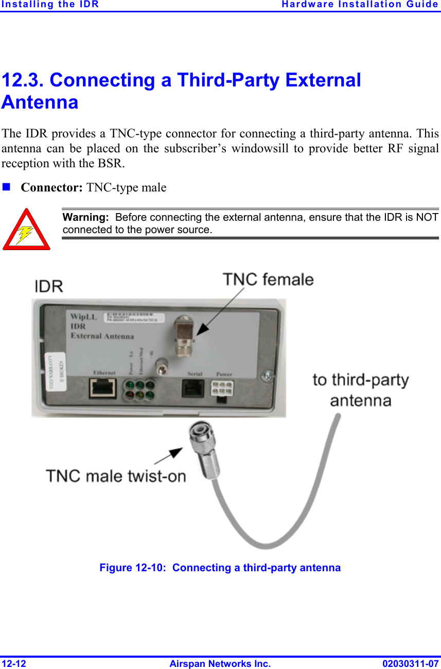
- 3. External Antenna Information
- 4. Internal Antenna Information
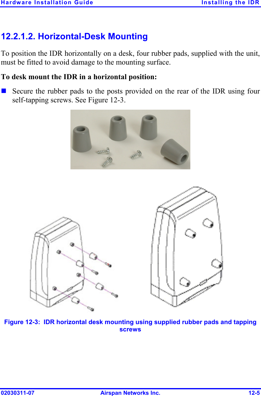
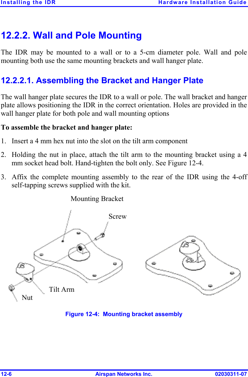
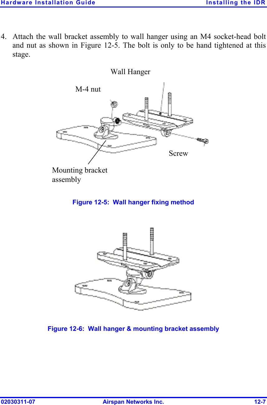
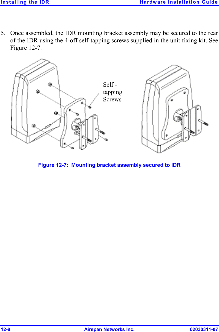
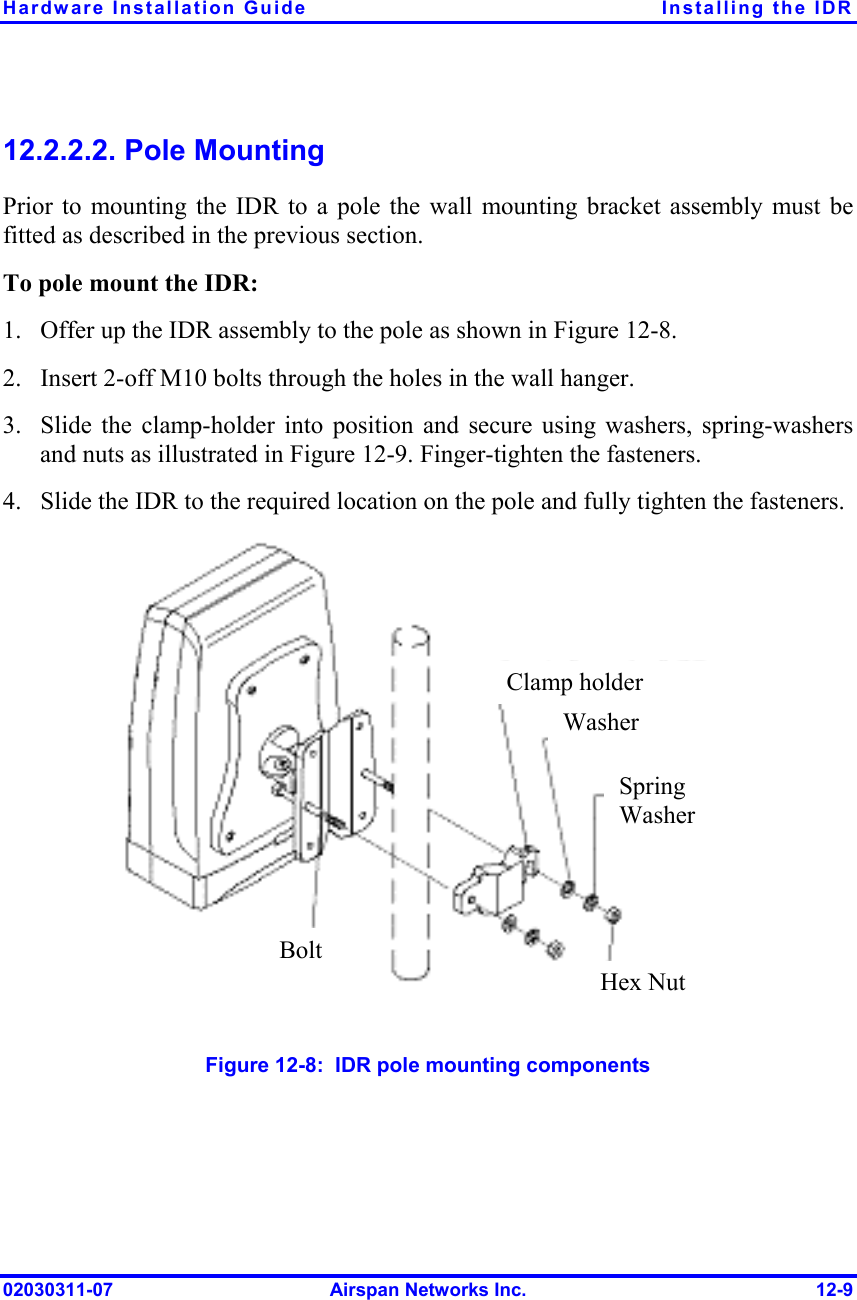
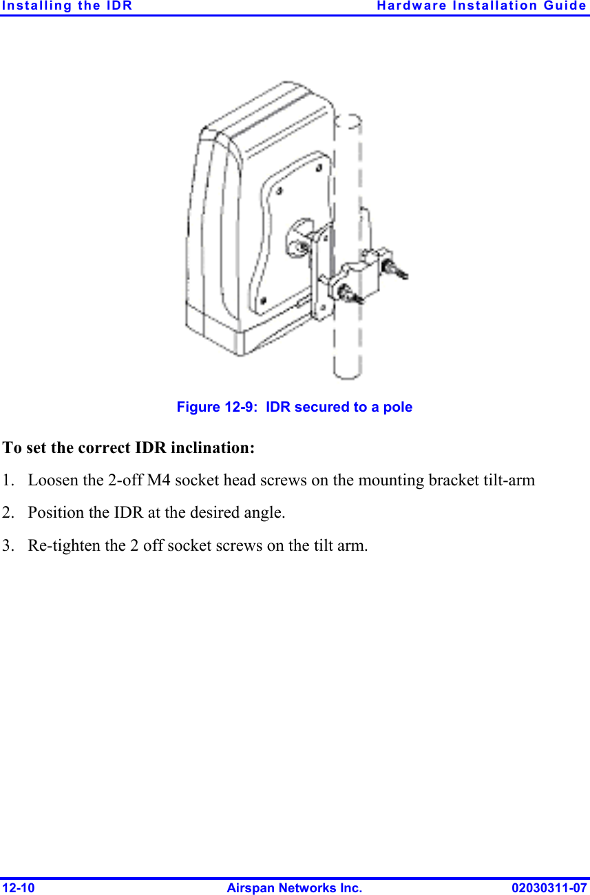
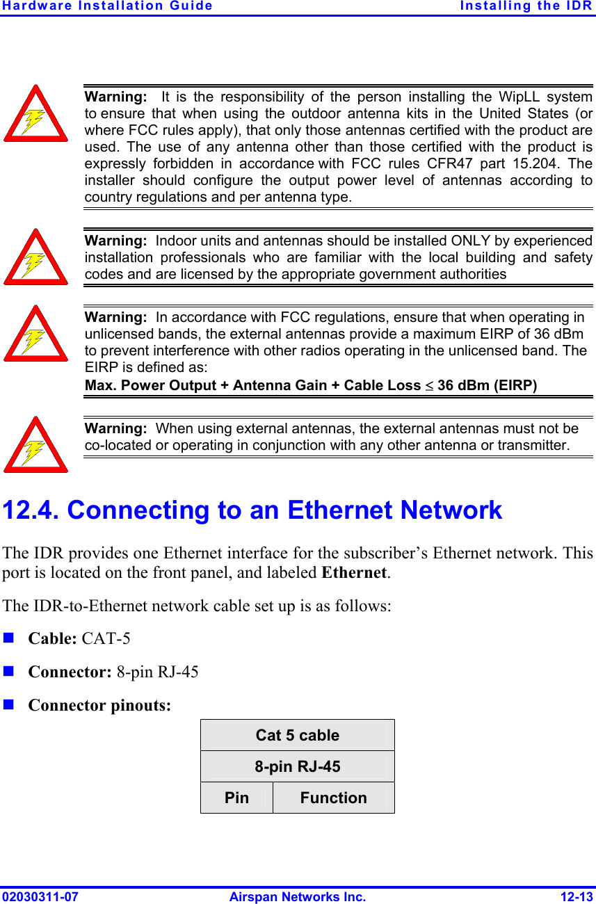
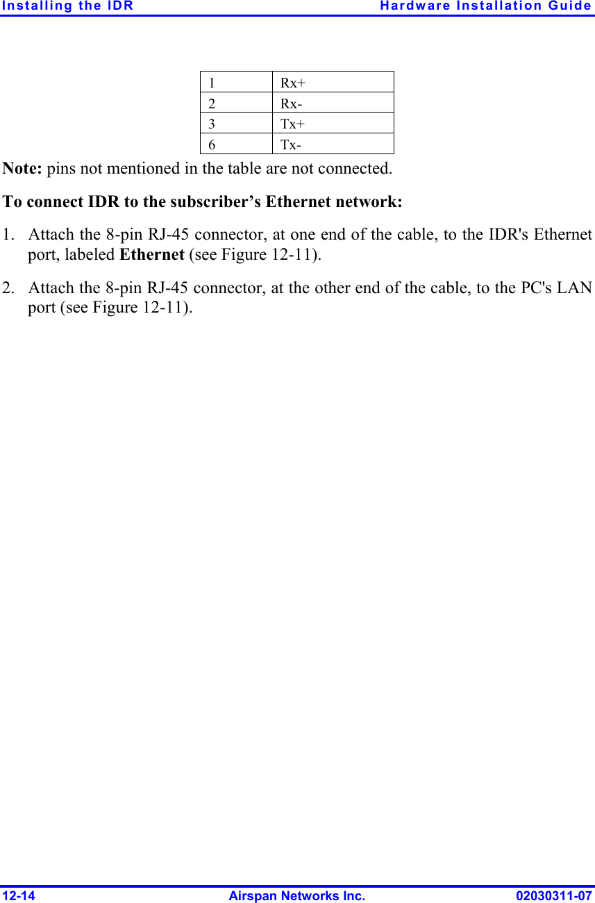
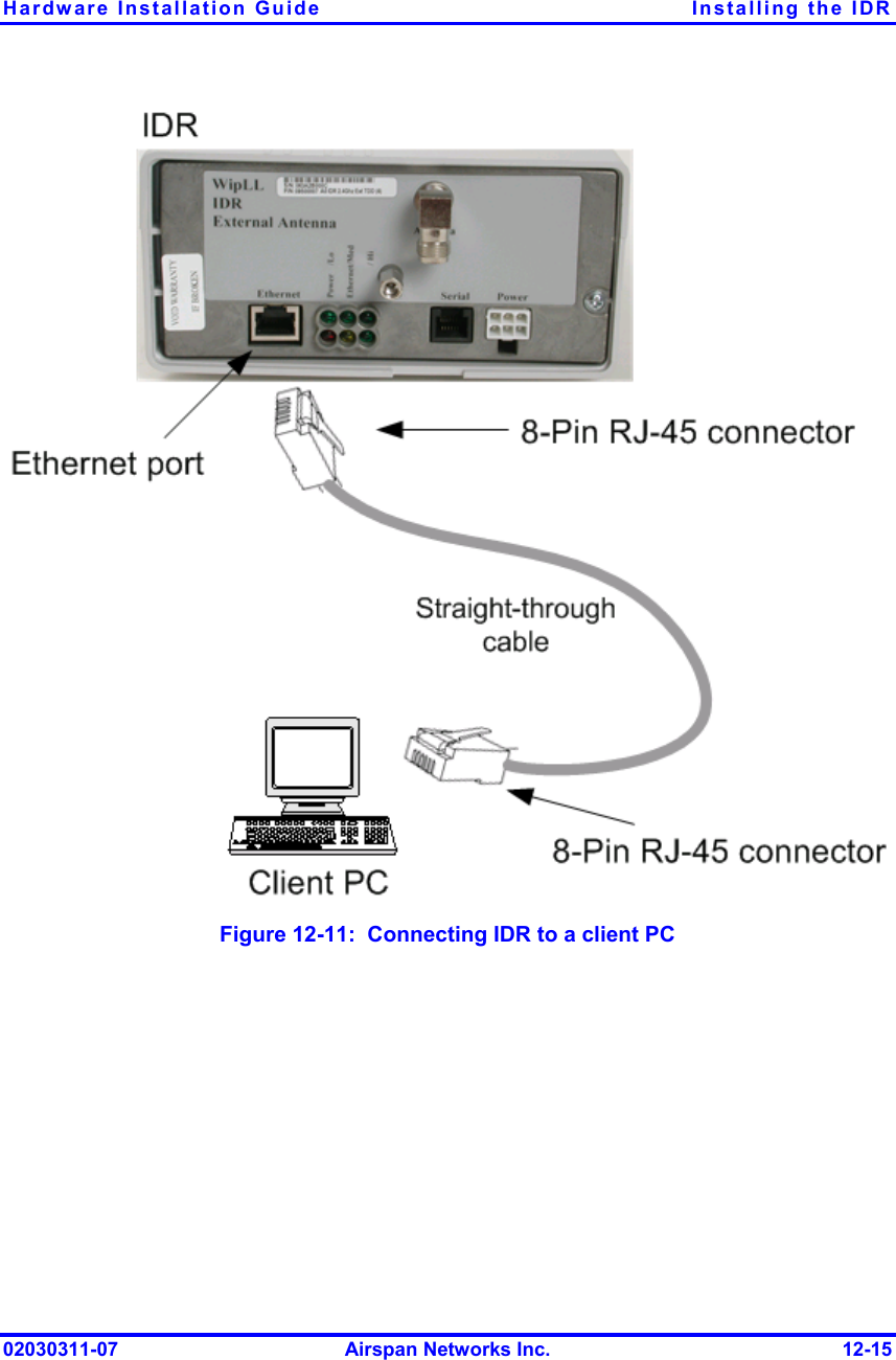
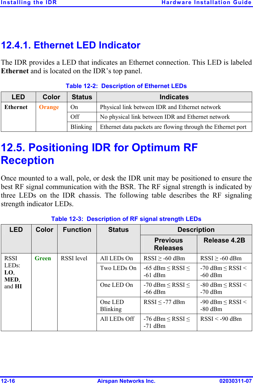
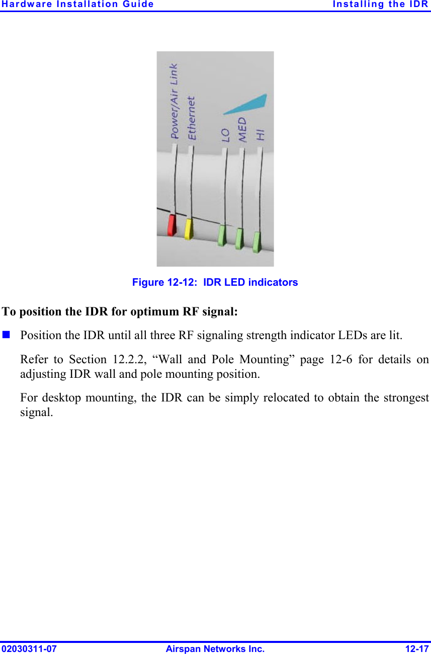
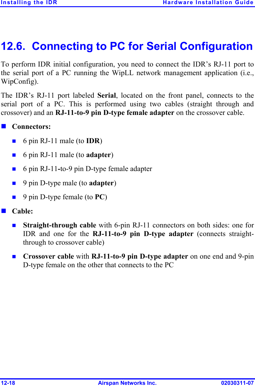
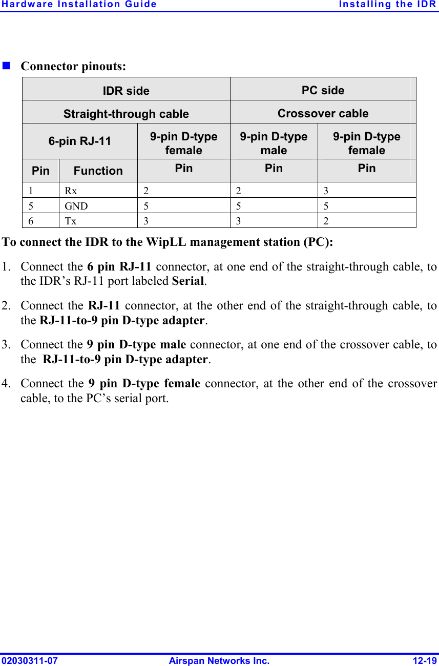
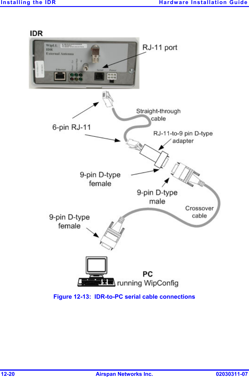
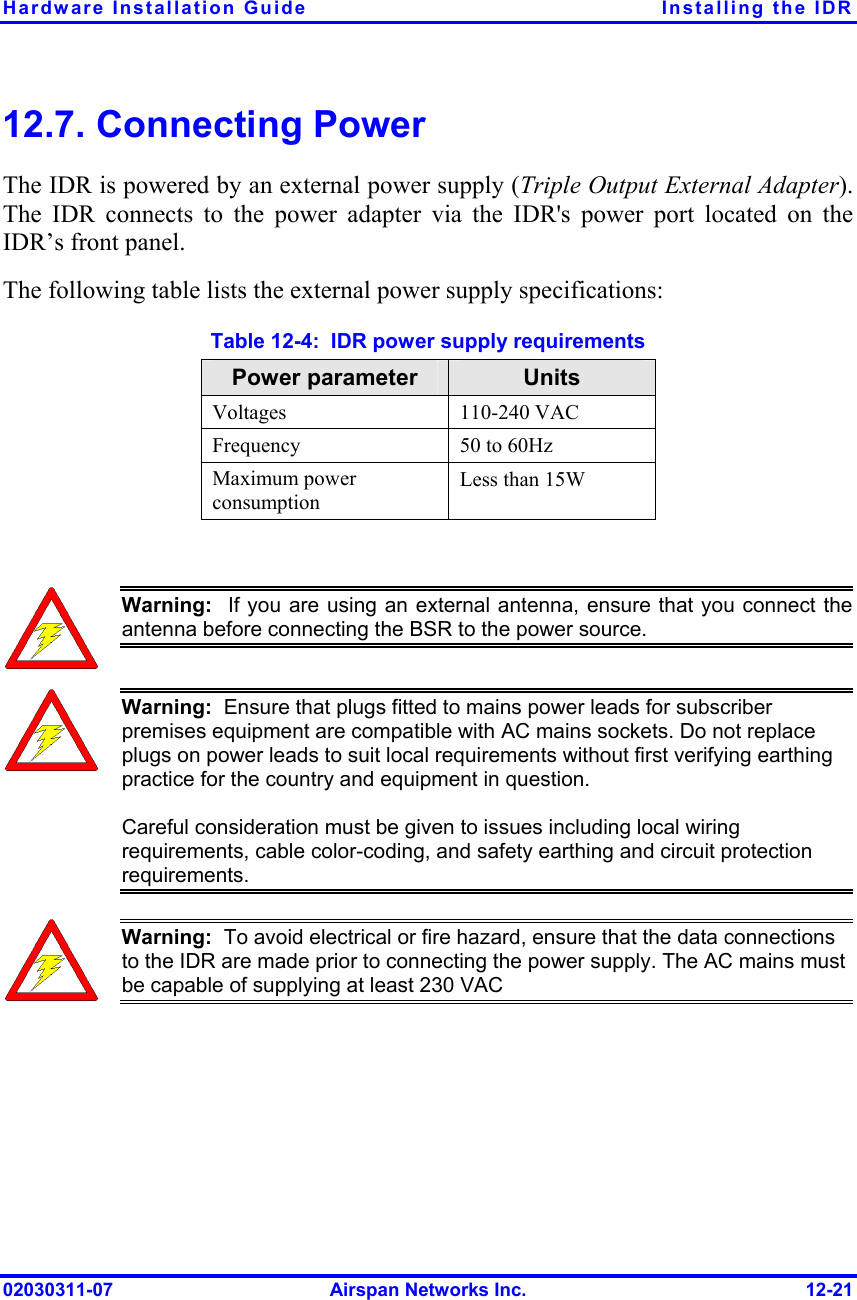
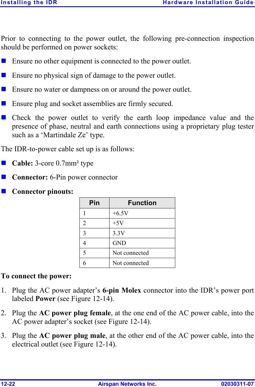
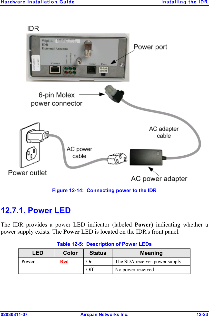
Installation Revised