Airspan Networks ASMAX56 Subscriber (terminal) station User Manual ProST Installation User Guide
Airspan Networks Inc Subscriber (terminal) station ProST Installation User Guide
UserManual.wiki
>
Airspan Networks
>
ASMAX56 User Manual
>
Users manual
Contents
1.
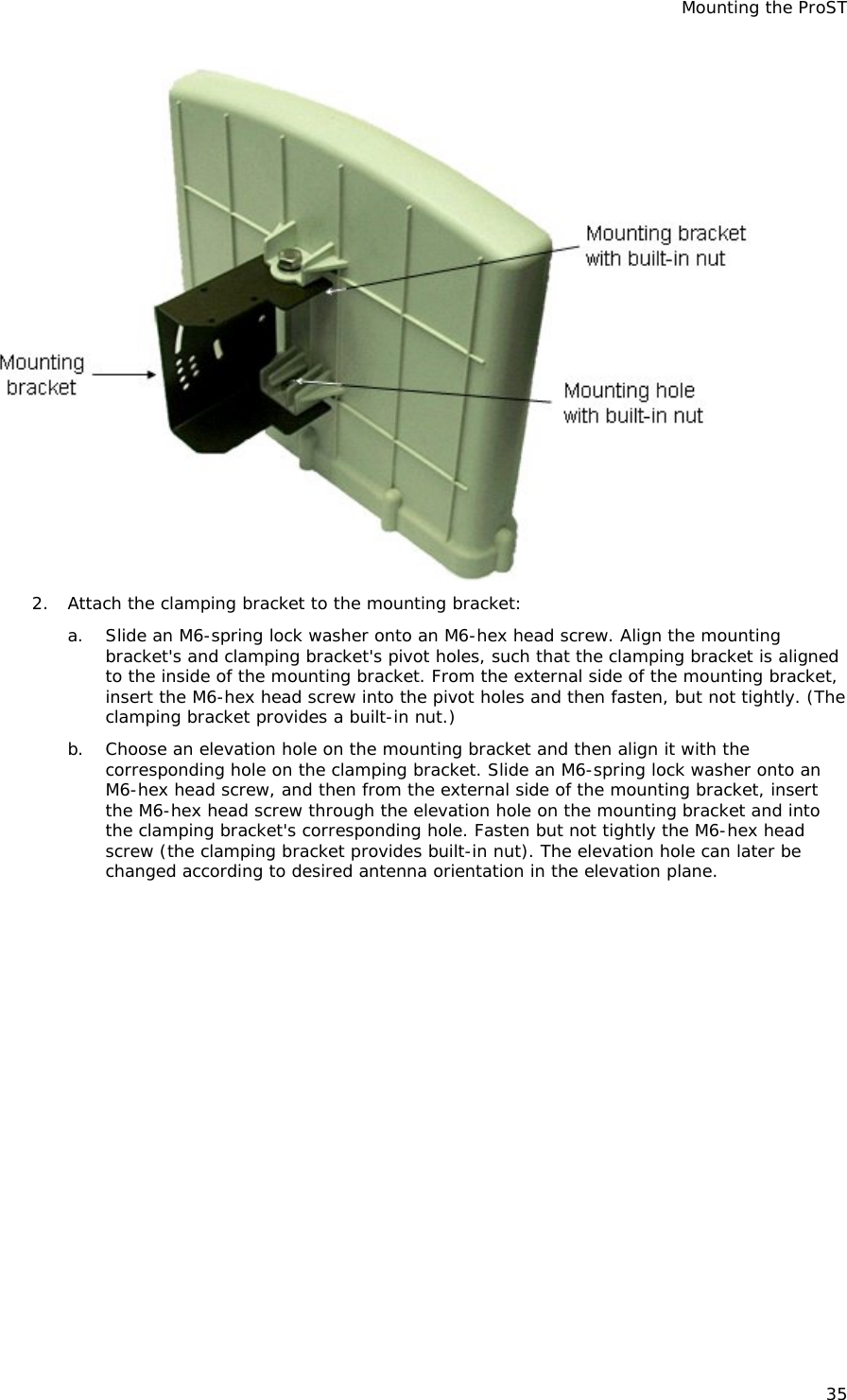
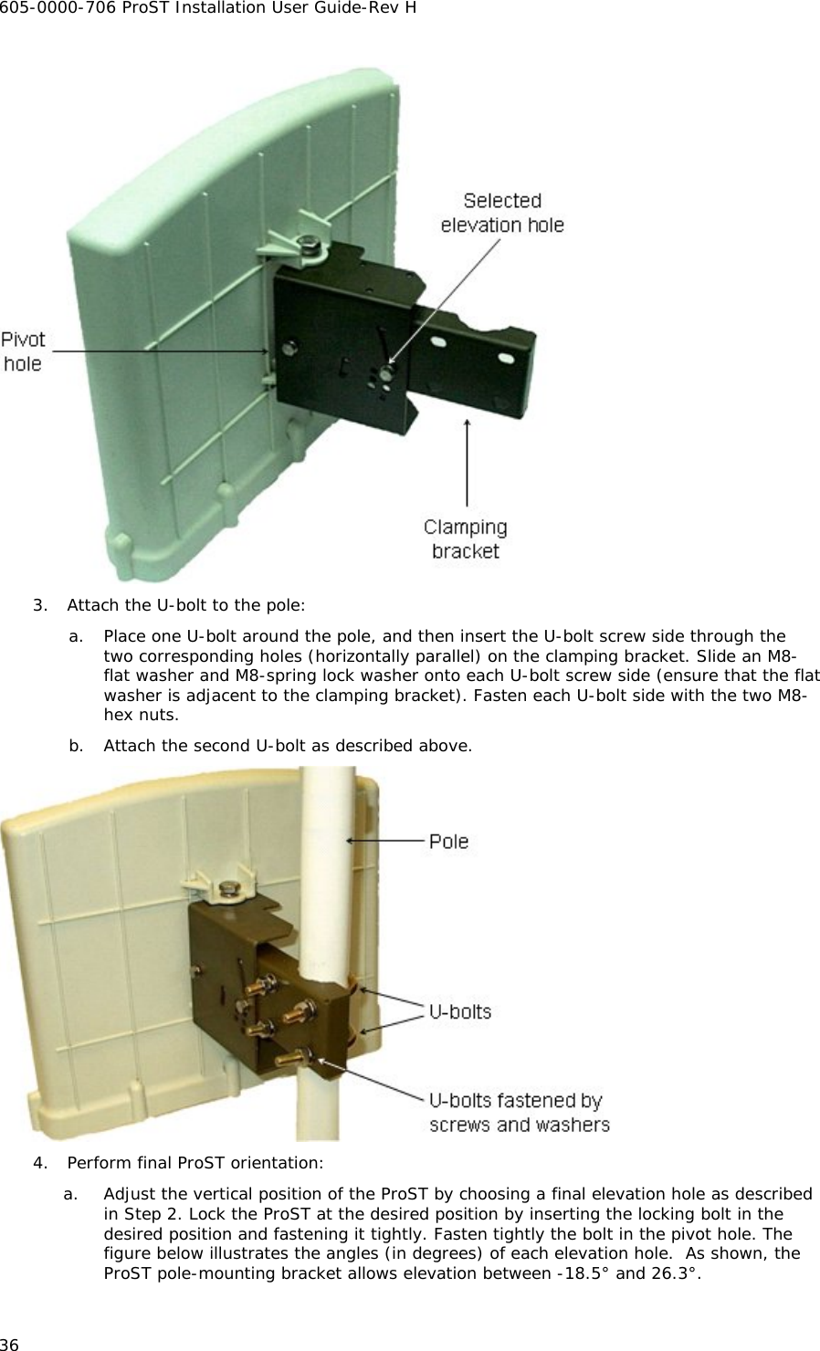
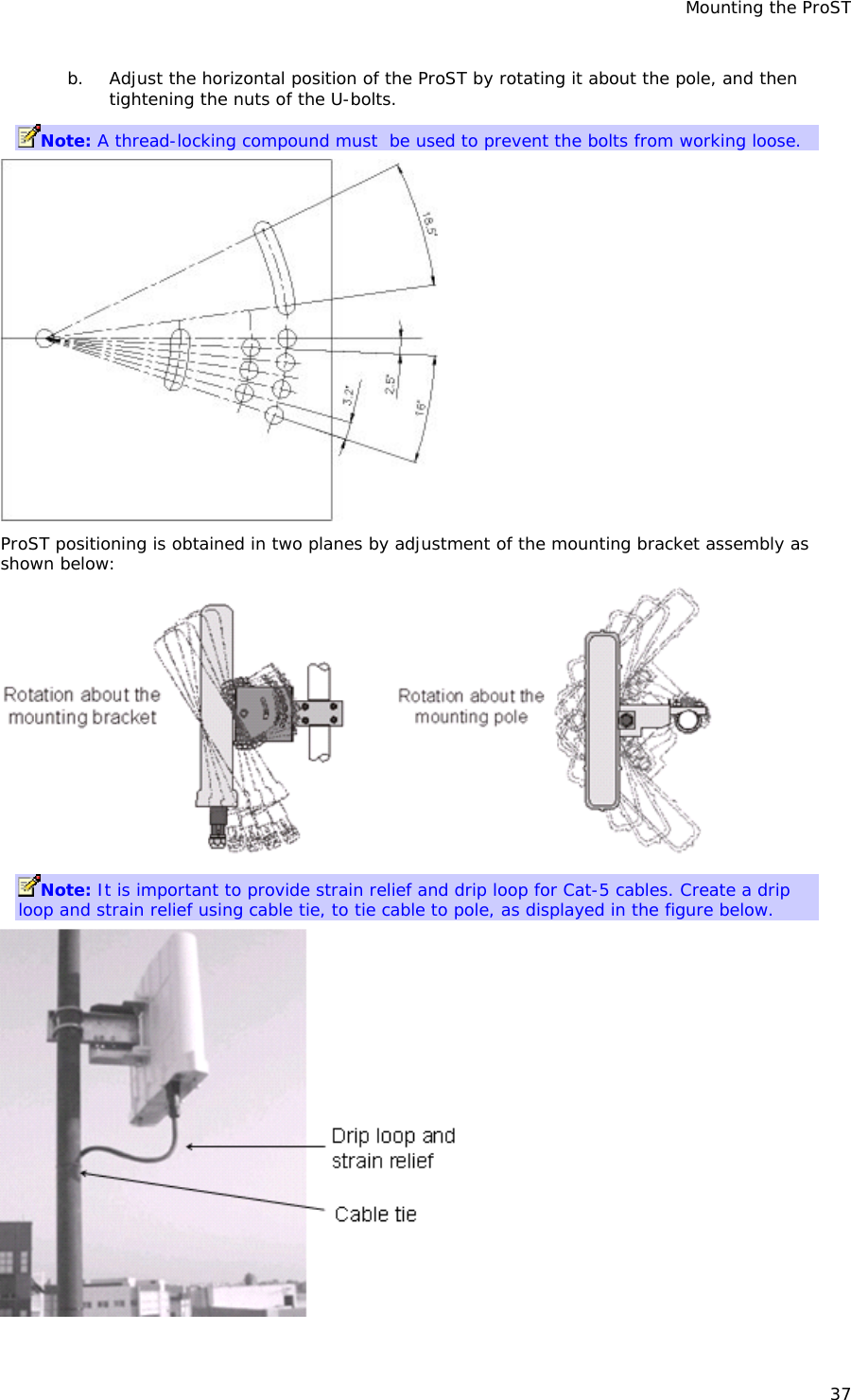
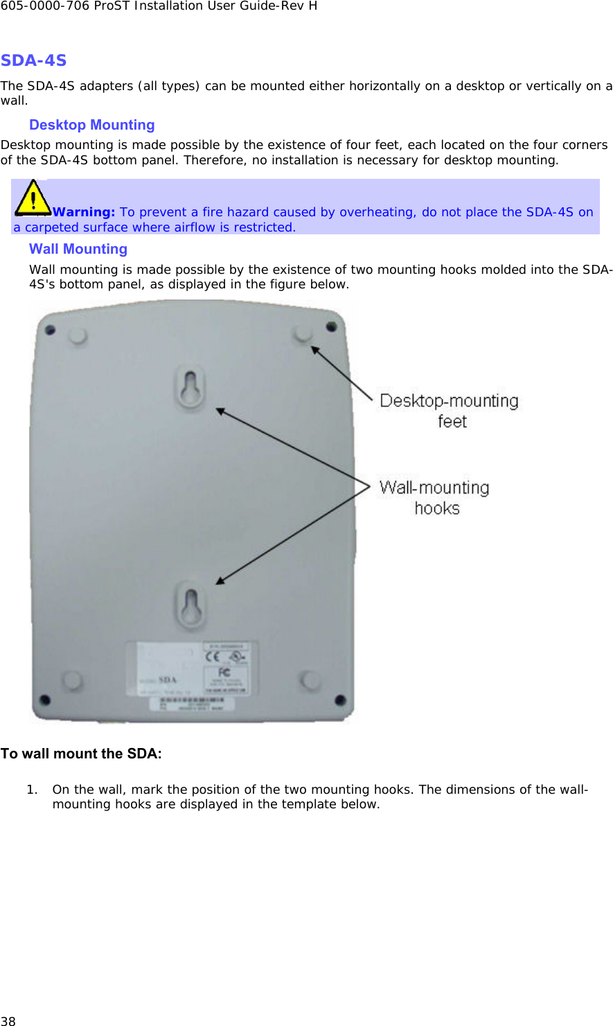
Users manual
2.
DFS Link instructions
Users manual
Navigation menu
Upload a User Manual
Namespaces
Wiki Guide
HTML
PDF
Info
Views
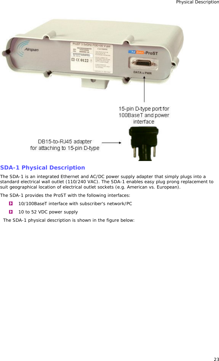
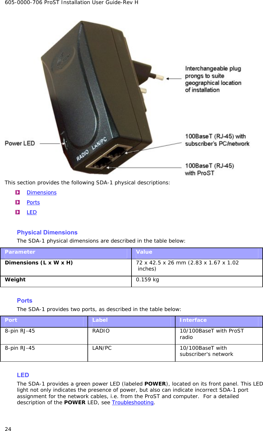
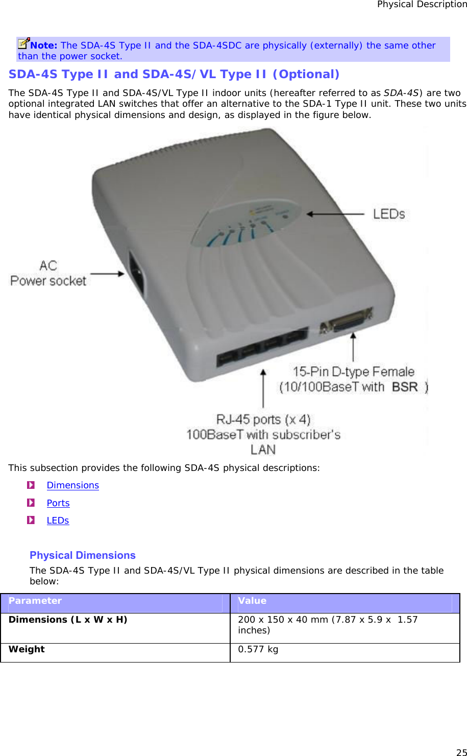
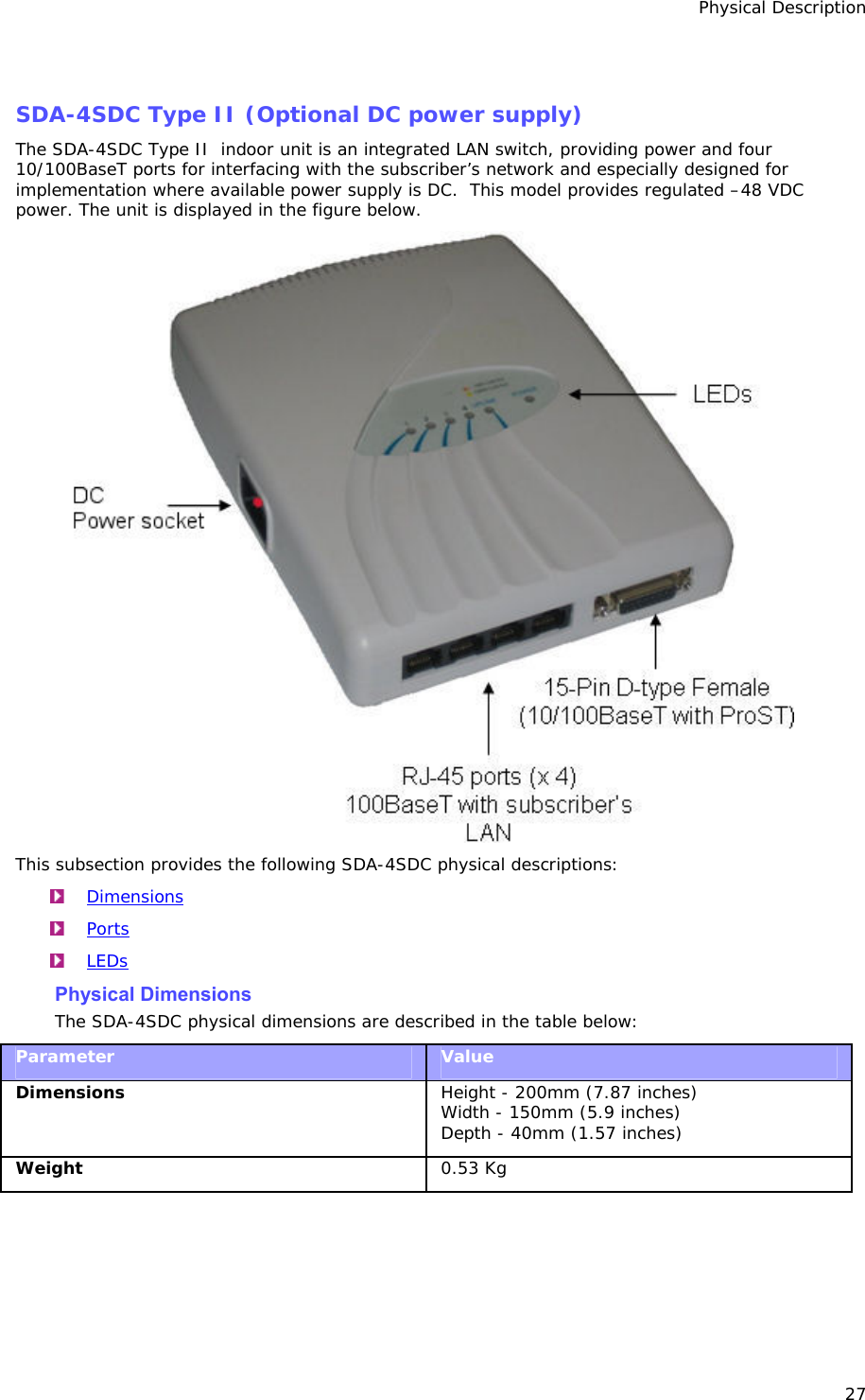
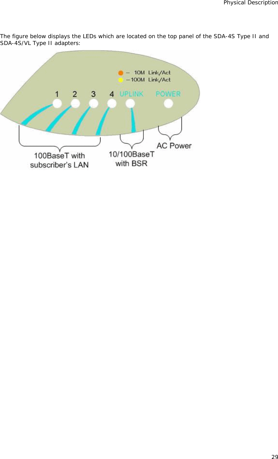
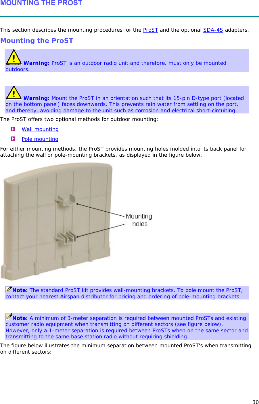
User Manual
Discussion / Help
Navigation