Airspan Networks ASMAX56 Subscriber (terminal) station User Manual ProST Installation User Guide
Airspan Networks Inc Subscriber (terminal) station ProST Installation User Guide
Contents
- 1. Users manual
- 2. DFS Link instructions
Users manual

1
IP-based
Broadband Wireless Access (BWA) System
605-0000-706 Rev H
ProST
Hardware Installation Guide
The Innovation Behind Broadband Wireless
Connecting the World
605-0000-706 ProST Installation User Guide-Rev H
2
Table Of Contents
Introduction.......................................................................................................................5
Purpose..........................................................................................................................5
Targeted Audience ...........................................................................................................5
Referenced Documentation................................................................................................5
Conventions....................................................................................................................5
Warnings and Cautions........................................................................................................6
Human Exposure to Radio Frequencies................................................................................6
Radio Interference ...........................................................................................................6
Avoiding Radio Interference...............................................................................................6
Modifications ...................................................................................................................6
General ..........................................................................................................................6
Manufacturer's Disclaimer Statement ..................................................................................6
Declaration of Conformity ....................................................................................................8
European Community, Switzerland, Norway, Iceland, and Liechtenstein ...................................8
Declaration of Conformity with Regard to the R&TTE Directive 1999/5/EC.................................8
Fcc Interference Statement................................................................................................ 10
Federal Communication Commission Interference Statement................................................ 10
Maximum Output TX Power ............................................................................................. 11
System Overview.............................................................................................................. 12
ProST Frequency Ranges................................................................................................. 13
Main Features................................................................................................................ 13
Architecture .................................................................................................................. 14
ProST Models.............................................................................................................. 15
ProST Block Diagram ................................................................................................... 16
ProST Protocol Stack ...................................................................................................... 16
Theory of Operation ....................................................................................................... 17
Installation Prerequisites.................................................................................................... 18
Package Contents........................................................................................................... 18
Minimum PC Requirements.............................................................................................. 18
Required Tools............................................................................................................... 18
Radio Site Planning ........................................................................................................ 19
Minimal Radio Path Obstructions.................................................................................... 19
Fresnel Zone Clearance................................................................................................ 19
Multipath Fading ......................................................................................................... 21
Radio Antenna Alignment ............................................................................................. 21
Physical Description .......................................................................................................... 22
ProST Physical Description............................................................................................... 22
Physical Dimensions..................................................................................................... 22
Introduction
3
Port........................................................................................................................... 22
SDA-1 Physical Description.............................................................................................. 23
Physical Dimensions..................................................................................................... 24
Ports ......................................................................................................................... 24
LED........................................................................................................................... 24
SDA-4S Type II and SDA-4S/VL Type II (Optional).............................................................. 25
Physical Dimensions..................................................................................................... 25
Ports ......................................................................................................................... 26
LEDs ......................................................................................................................... 26
SDA-4SDC Type II (Optional DC power supply) .................................................................. 27
Physical Dimensions..................................................................................................... 27
Ports ......................................................................................................................... 28
LEDs ......................................................................................................................... 28
Mounting the ProST........................................................................................................... 30
Mounting the ProST........................................................................................................ 30
Wall Mounting................................................................................................................ 31
Pole Mounting................................................................................................................ 33
SDA-4S ........................................................................................................................ 38
Desktop Mounting ....................................................................................................... 38
Wall Mounting............................................................................................................. 38
Network Cabling ............................................................................................................... 40
Connecting to IDU.......................................................................................................... 40
Using the SDA-1 Type II............................................................................................... 40
Using the SDA-4S Type II, SDA-4S/VL Type II or SDA-4S/DC Type II ................................. 41
Connecting to LAN Network ............................................................................................. 43
Using SDA-1 Type II.................................................................................................... 43
Using the SDA-4S Type II, SDA-4S/VL Type II or SDA-4S/DC Type II ................................. 45
Using SDA-MSG .......................................................................................................... 47
Using SDA-WiFi........................................................................................................... 48
Connecting to Power ......................................................................................................... 50
DC Power Source ........................................................................................................... 50
Connecting the SDA-4SDC Type II (Optional DC adapter)..................................................... 51
AC Power Source ........................................................................................................... 53
Using SDA-1 Type II.................................................................................................... 53
Using SDA-4S Type II and SDA-4S/VL Type II ................................................................. 55
Connecting Power Cable for SDA-4SDC ................................................................................ 57
Power Cable Connection.................................................................................................. 57
Housing the Connectors................................................................................................ 57
Connecting to the SDA-4SDC ........................................................................................ 57
Connecting Lightning and Surge Protector ............................................................................ 59
605-0000-706 ProST Installation User Guide-Rev H
4
PolyPhaser Wiring Diagram.............................................................................................. 60
Lightning and Surge Protection Connection Scenarios ....................................................... 61
RSSI LED Plug Adapter ...................................................................................................... 64
Antenna Alignment using RSSI LED Plug Adapter................................................................ 64
LED Status.................................................................................................................... 65
Connecting External Antenna.............................................................................................. 67
Troubleshooting................................................................................................................ 69
Trademarks and Copyrights................................................................................................ 70
Contact Information.......................................................................................................... 71
Revisions......................................................................................................................... 72
Warnings......................................................................................................................... 73
1. Disclaimer................................................................................................................. 73
1.1 Safety Warnings....................................................................................................... 73
1.2 Important Warning Symbols....................................................................................... 73
1.3 Important Service Information.................................................................................... 74
1.4 UL Information......................................................................................................... 74
1.5 CE Notice ................................................................................................................ 74
1.6 European Community, Switzerland, Norway, Iceland, and Liechtenstein............................ 75
Declaration of Conformity with Regard to the R&TTE Directive 1999/5/EC............................ 75
1.7 CAUTION................................................................................................................. 76
1.8 Lightning Protection .................................................................................................. 76
Glossary.......................................................................................................................... 78
Index.............................................................................................................................. 81
Introduction
5
INTRODUCTION
Thank you for purchasing Airspan's ProST wireless access device. The ProST customer premise
equipment (CPE) is part of Airspan's AS.MAX family of WiMAX-based products.
This section provides a preface by discussing the purpose, audience, organization, conventions, and
customer support of this guide.
Purpose
This guide provides step-by-step instructions for setting up and installing the ProST.
Targeted Audience
This guide is intended for the technician who is qualified and authorized to install the ProST.
Referenced Documentation
For a detailed description of the Web-based configuration tool, refer to the WiMAX Web-based
Management User's Guide.
Conventions
This guide uses the following typographical conventions:
Convention Meaning Example
Bold Command, menu, icon,
button, and field Click the Next button.
"To" in bold face and at the
beginning of a sentence Introduces a numbered
procedure To download a SW file:
Warning that provides
information that can prevent
and avoid bodily or
mechanical harm
--
Note that provides useful
information --

605-0000-706 ProST Installation User Guide-Rev H
6
WARNINGS AND CAUTIONS
Human Exposure to Radio Frequencies
The ProST should be installed and operated from a minimum distance of 20 cm to your body.
Radio Interference
This equipment generates, uses, and can radiate radio frequency energy and, if not installed and
used in accordance with the instructions, may cause harmful interference to radio communications.
However, there is no guarantee that interference will not occur in a particular installation. If this
equipment does cause harmful interference to radio or television reception, which can be
determined by turning the equipment on and off, the user is encouraged to try to correct the
interference by performing one or more of the following measures:
Reorientate or relocate the receiving antenna
Increase separation between the equipment and receiver
Connect the equipment to an outlet on a circuit different from that to which the receiver is
connected
Consult the dealer or an experienced radio/TV technician for help
Avoiding Radio Interference
This transmitter must not be co-located or operating in conjunction with any antenna or
transmitter.
Ensure a minimum of 1-meter separation between co-located ProST's.
When using an external antenna, the external antenna must not be co-located or operating
in conjunction with any other antenna or transmitter.
Modifications
Any changes and modifications to this device that are not expressly approved by Airspan may void
the user's authority to operate the equipment.
General
Only qualified personnel should be allowed to install, replace, and service the equipment.
The device cannot be sold retail, to the general public or by mail order. It must be sold to
dealers.
Installation must be controlled.
Installation must be performed by licensed professionals.
Installation requires special training.
The AS.MAX radios and antennas should be installed ONLY by experienced installation
professionals who are familiar with local building and safety codes and, wherever
applicable, are licensed by the appropriate government regulatory authorities. Failure to do
so may void Airspan's AS.MAX product warranty and may expose the end user or the
service provider to legal and financial liabilities. Airspan and its resellers or distributors are
not liable for injury, damage or violation of regulations associated with the installation of
outdoor units or antennas.
Do not mount outdoor radios and external antennas in weather that may increase risk of
electrocution such as rain or lightning.
To prevent ESD damage to devices, always wear an ESD wrist strap when handling these
devices or coming into contact with internal components.
Manufacturer's Disclaimer Statement
Introduction
7
The information in this document is subject to change without notice and does not represent a
commitment on the part of the vendor. No warranty or representation, either expressed or implied,
is made with respect to the quality, accuracy or fitness for any particular purpose of this document.
The manufacturer reserves the right to make changes to the content of this document and/or the
products associated with it at any time without obligation to notify any person or organization of
such changes. In no event will the manufacturer be liable for direct, indirect, special, incidental or
consequential damages arising out of the use or inability to use this product or documentation, even
if advised of the possibility of such damages. This document contains materials protected by
copyright. All rights are reserved. No part of this manual may be reproduced or transmitted in any
form, by any means or for any purpose without expressed written consent of its authors. Product
names appearing in this document are mentioned for identification purchases only. All trademarks,
product names or brand names appearing in this document are registered property of their
respective owners.

605-0000-706 ProST Installation User Guide-Rev H
8
DECLARATION OF CONFORMITY
European Community, Switzerland, Norway, Iceland, and
Liechtenstein
Declaration of Conformity with Regard to the R&TTE Directive
1999/5/EC
English:
This equipment is in compliance with the essential requirements and other relevant
provisions of Directive 1999/5/EC.
Deutsch:
Dieses Gerät entspricht den grundlegenden Anforderungen und den weiteren
entsprecheneden Vorgaben der Richtlinie 1999/5/EU.
Dansk:
Dette udstyr er i overensstemmelse med de væsentlige krav og andre relevante
bestemmelser i Directiv 1999/5/EF.
Español:
Este equipo cumple con los requisitos esenciales asi como con otras disposiciones de la
Directive 1999/5/EC.
Greek:
ΜΕ ΤΗΝ ΠΑΡΟΥΣΑ Airspan ∆ΗΛΩΝΕΙ ΟΤΙ Ο ΕΞΟΠΛΙΣΜΟΣ ΣΥΜΜΟΡΦΩΝΕΤΑΙ ΠΡΟΣ ΤΙΣ
ΟΥΣΙΩ∆ΕΙΣ ΑΠΑΙΤΗΣΕΙΣ ΚΑΙ ΤΙΣ ΛΟΙΠΕΣ ΣΧΕΤΙΚΕΣ ∆ΙΑΤΑΞΕΙΣ ΤΗΣ Ο∆ΗΓΙΑΣ 1999/5/ΕΚ.
Français:
Cet appareil est conforme aux exigencies essentialles et aux autres dispositions pertinantes
de la Directive 1999/5/EC.
Íslenska:
Þessi búnaður samrýmist lögboðnum kröfum og öðrum ákvæðum tilskipunar 1999/5/ESB.
Italiano:
Questo apparato é conforme ai requisiti essenziali ed agli altri principi sanciti dalla Direttiva
1999/5/EC.
Nederlands:
Deze apparatuur voldoet aan de belangrijkste eisen en andere voorzieningen van richtlijn
1999/5/EC.
Norsk:
Dette utstyret er i samsvar med de grunnleggende krav og andre relevante bestemmelser i
EU-directiv 1999/5/EC.
Português:
Este equipamento satisfaz os requisitos essenciais e outras provisões da Directiva
1999/5/EC.
Suomalainen:
Tämä laite täyttää direktiivin 1999/5/EY oleelliset vaatimukset ja on siinä asetettujen
muidenkin ehtojen mukainen.
Svenska:

Introduction
9
Denna utrustning är i överensstämmelse med de väsentliga kraven och andra relevanta
bestämmelser i Direktiv 1999/5/EC.
The Declaration of Conformity related to this product can be obtained from
product_management@Airspan.com

605-0000-706 ProST Installation User Guide-Rev H
10
FCC INTERFERENCE STATEMENT
Federal Communication Commission Interference Statement
This equipment has been tested and found to comply with the limits for a Class B digital device,
pursuant to Part 15 of the FCC Rules. These limits are designed to provide reasonable protection
against harmful interference in a residential installation. This equipment generates, uses and can
radiate radio frequency energy and, if not installed and used in accordance with the instructions,
may cause harmful interference to radio communications. However, there is no guarantee that
interference will not occur in a particular installation. If this equipment does cause harmful
interference to radio or television reception, which can be determined by turning the equipment off
and on, the user is encouraged to try to correct the interference by one of the following measures:
Reorient or relocate the receiving antenna.
Increase the separation between the equipment and receiver.
Connect the equipment into an outlet on a circuit different from that to which the receiver is
connected.
Consult the dealer or an experienced radio/TV technician for help.
This device complies with Part 15 of the FCC Rules. Operation is subject to the following two
conditions: (1) This device may not cause harmful interference, and (2) this device must accept any
interference received, including interference that may cause undesired operation.
FCC Caution: Any changes or modifications not expressly approved by the party responsible for
compliance could void the user's authority to operate this equipment.
IMPORTANT NOTE:
FCC Radiation Exposure Statement:
This equipment complies with FCC radiation exposure limits set forth for an uncontrolled
environment. This equipment should be installed and operated with minimum distance 20cm
between the radiator & your body.
This transmitter must not be co-located or operating in conjunction with any other antenna or
transmitter.

Introduction
11
Maximum Output TX Power
CPE Maximum Output TX Power
Caution: Do not set maximum output TX power to higher than local regulations.

12
SYSTEM OVERVIEW
The ProST is an outdoor WiMAX-based customer premises equipment (CPE). The ProST, which uses
Intel Corporation’s Pro/Wireless 5116 broadband interface, connects IP-enabled devices directly to
WiMAX networks. Designed for the residential and small enterprise (SME) markets, the device
supports high-speed broadband Internet through a Fast Ethernet connection.
The ProST ensures high service availability at enhanced ranges, operating in both LOS and NLOS
propagation environments. ProST uses the OFDM signaling format, providing non line-of-sight
(NLOS) performance. ProST utilizes QAM, QPSK, and BPSK modulation technologies by modulating
transmitted signals and demodulating the received signals where the original digital message can be
recovered. The use of adaptive modulation allows ProST to optimize throughput, yielding higher
throughputs while also covering long distances.
ProST models support IP services at speeds of up to 37 Mbit/s over-the-air gross rates over channel
bandwidths of up to 10 MHz in both uplink and downlink. ProST is available in numerous ETSI
frequency bands, operating in FDD and TDD modes in numerous channels, see: ProST Frequency
Ranges.
ProST can be deployed with a built-in, integral antenna or alternatively, with an external antenna to
provide better radio coverage. Requiring professional installation, the ProST is installed outdoors on
a pole or wall, enabling optimal positioning for best reception with the BS. Outdoor mounting of the
ProST is made possible due to ProST's built-in lightning surge protection feature (complying with
Surge Immunity standard EN 61000-4-5).
ProST is powered through the SDA-1 Type II (referred henceforth as SDA-1) adapter which
interfaces with the subscriber's LAN. ProST connects to the SDA-1's 100BaseT interface port by a
standard 100-meter CAT-5 cable. The SDA-1 also provides the ProST with 10 to 52 VDC power
supply. However, as an alternative to these adapters, Airspan offers three optional integrated LAN
switches:
SDA-4S Type II: A standard integrated LAN switch, providing four 10/100BaseT interfaces
with the subscriber’s computers. This model is ideal for SOHO implementation.
SDA-4S/VL Type II: Provides VLANs between ports and the ProST, ensuring privacy
between LAN users of the different ports. For example, all users connected to Port 1 do not
"see" users connected to Port 2. This model is ideal for multi-tenant (VLAN security)
implementation.
SDA-4S/DC Type II: integrated LAN switch, providing power and four 10/100BaseT
interfaces and especially designed for implementation where available power supply is DC
(10 to 52 VDC), e.g. from a solar panel. This model provides regulated –48 VDC power to
the BSR.
All SDA types work in VLAN Pass-through mode. Tagged and Untagged packets are forwarded
transparently by the SDA. The SDA has no VLAN ID configuration per port.
ProST can be managed by Airspan's Web-based management system using standard Web browsers
or alternatively, by an SNMP-based network management system (Netspan) using standard and
proprietary MIBs. In addition, external third-party management systems such as HP OpenView can
also manage the ProST using these MIBs.
System Overview
13
ProST Frequency Ranges
The table below lists the frequency range of ProST models currently available. This table will grow
as more models become available.
Frequency Band Channel Bandwidth
3.3 – 3.5 GHz in TDD mode 1.75 MHz
2.75 MHz
3.5 MHz
5 MHz
3.4 – 3.6 GHz in FDD mode 1.75 MHz
3.5 MHz
3.6 – 3.8 GHz in TDD mode 1.75 MHz
3.5 MHz
5 MHz
4.9 – 5.0 GHz in TDD mode 2.5 MHz
5 MHz
10 MHz
5.47 – 5.725 GHz in TDD mode 2.5 MHz
5 MHz
10 MHz
5.725 – 5.875 GHz in TDD mode 2.5 MHz
5 MHz
10 MHz
5.850 – 5.950 GHz in TDD mode 2.5 MHz
5 MHz
10 MHz
Main Features
The ProST provides the following main features:
Full Outdoor Non-LOS Deployment: 256 OFDM
Based on the latest wireless technology WiMAX IEEE 802.16 standard
Integrated antenna gain of 15 dBi or 17 dBi (latest version)
Indoor Ethernet adapter (SDA-1 Type II):
o providing power and interface termination
o up to 100-m Category 5 cable between ProST and SDA-1
Indoor:
o SDA-4S Type II: small low cost IDU with built in LAN switch
o SDA-4SDC Type II: small low cost DC IDU with built in LAN Switch

605-0000-706 ProST Installation User Guide-Rev H
14
o SDA-WiFi: enabling WiFi capability to the ProST CPE (optional)
o SDA-MSG (Multi-Service Gateway): enabling VoIP capability to the ProST CPE
(optional)
High throughput providing fast access at burst data rates up to 37 Mbps over-the-air (gross
rate) over up to a 10 MHz channel
Option of LAN switch with indoor adapter
Up to 4 ports with VLAN port switching
Supports multiple UL bursts per SS frame
Signal information can be obtained via Web Management Performance tool
Integral WiFi and LAN switch
Optional VoIP module -- available SDA-MSG, an extension module allowing you to add VoIP
functionality to your ProST unit(s).
Optional WiFi module -- available SDA-WiFi, an extension module allowing you to add WiFi
functionality to your ProST unit(s).
Note: Contact your Airspan representative for more information on the SDA-MSG VoIP
extension module or the SDA-WiFi extension module.
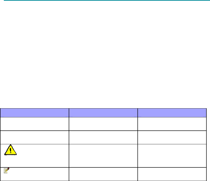
Architecture
The ProST installation consists of the following components:
Encased ProST outdoor unit (available in two variations)
SDA-1 indoor adapter or optional SDA-4S Type II, SDA-4S/VL Type II, or SDA-4S/DC Type
II
Third-party external antenna (optional deployment)
Note: The SDA-1 Type II adapter can also be implemented with other Airspan's ASWipLL
radios (i.e. BSR, PPR, and SPR). For further information regarding these products, please
contact your nearest Airspan dealer.
The figure below displays a typical architecture setup of the ProST with an integrated antenna.
System Overview
15
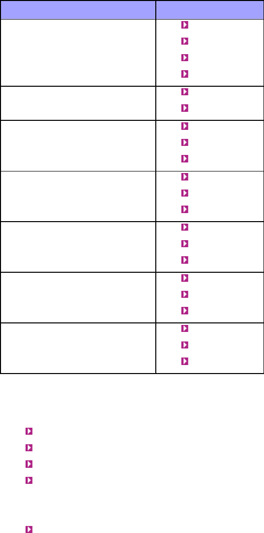
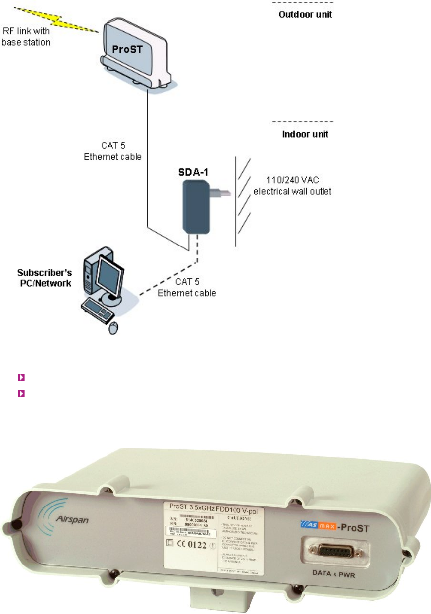
ProST Models
The ProST is available in the following variations, differing in antenna configuration:
ProST with built-in (integrated), flat-panel antenna
ProST with N-type connector for attaching third-party external antenna (i.e. no integrated
antenna)
The ProST model with the integrated antenna is shown below:
The ProST model with the N-type connector for connecting an external antenna is shown below:
605-0000-706 ProST Installation User Guide-Rev H
16
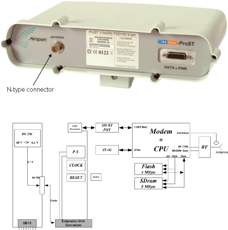
ProST Block Diagram
The figure below displays a block diagram of the ProST:
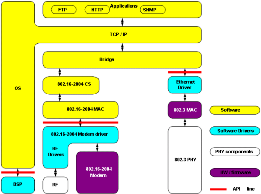
ProST Protocol Stack
The figure below displays a block diagram of the ProST's network architecture, designed as a
hierarchy of protocols (i.e. protocol stack) implemented in the communication network.
System Overview
17
Theory of Operation
For basic operation, the ProST requires no initial configuration--simply plug and play. Configuration
is automatically performed over the air by the BS. The ProST is preconfigured by the operator at the
BS (using Netspan) with service flow parameters such as the maximum information rate, the
committed information rate, the maximum latency, and maximum jitter. These configuration
parameters are stored in Netspan's database corresponding to the ProST's MAC address.
Before any communication between ProST and BS can occur, the ProST must be positioned in a
location that provides sufficient RF reception.
To join a network, the ProST needs to perform a few tasks. First, the "Network Entry" process
(defined in 802.16-2004) begins with the ProST scanning for a downlink (DL) signal from the base
station, and then synchronizing to the DL channel. Thereafter the ProST can start the process of
initial ranging, which alerts the BS to the presence of the ProST and establishment of management
connections to obtain basic and primary management connection IDs (CID) from the BS. After the
CIDs have been obtained, the ProST commences authorization and key exchange. In the final stage,
the ProST registers at the base station before obtaining the IP address, time of day and the
configuration file.
During Network entry, the ProST sends the BS its MAC address. The BS then accesses Netspan's
database (via SNMP) and checks whether the ProST's MAC address appears in the DB. If it locates
the MAC address, the BS retrieves all the ProST's configuration parameters (service flows) from the
DB and downloads them to the ProST device.
18
INSTALLATION PREREQUISITES
Before installing your ProST, read the following to ensure that:
No items are missing from the package
Minimum computer requirements are fulfilled
You have the required installation tools
Radio Site planning has been performed
Package Contents
Examine the ProST shipping container. If you notice any damage, or missing items as listed in the
Packing List, immediately notify the carrier that delivered the unit and contact a Airspan
representative.
The ProST kit should contain the following items:
ProST
DB15-to-RJ45 adapter for plugging into the ProST's 15-pin D-type port (with pins 7 & 8 not
connected), replaces previous adapter.
Wall-mounting kit:
o Mounting bracket
o 2 x M10 hex head screws
o 2 x M10 hex nuts
o 2 x M10 plain washers
o 2 x M10 spring lock washers
Note: The standard ProST kit does not include pole-mounting accessories. For pricing and
ordering of pole-mounting accessories, please contact your nearest Airspan dealer.
Note: The standard ProST kit does not include the SDA-1 Type II adapter. For pricing and
ordering of the SDA-1 Type II adapter, please contact your nearest Airspan dealer.
Minimum PC Requirements
Ensure that your computer provides an Ethernet interface such as a Network Interface Card (that
provides an RJ-45 port).
Warning: Only subscriber terminal equipment (e.g. computer modem port) that is
designed for full compliance with TNV-1 telecommunication network can be connected to the
SDA-1. Warranty of Airspan's equipment shall be made void if the SDA-1 is connected to a
computer that is not compliant with TNV-1.
Required Tools
The following tools are required to install the ProST unit:
Crimping tool for crimping CAT-5 cables to RJ-45 connectors
Cable stripping tool
Wall Mounting:
o drill bits
o 4 x wall anchors
o 4 x screws

Installation Prerequisites
19
o Philips head screwdriver
o Flat-blade screwdriver
o A/F open ended spanner
Crimping tool for crimping RF cable to N-type connector (only relevant when implementing
external antenna)
Torque wrench for N-type connectors (only relevant when implementing external antenna)
Note: Airspan does not provide screws and wall anchors for mounting the ProST to the
wall. The screw size depends on the structure of the building to which the ProST is to be
attached. When selecting screw sizes, consideration must be given to the weight of the ProST
and load that may be induced in windy conditions.
Radio Site Planning
Proper site selection and planning before installing your ProST will ensure a successful deployment
of your AS.MAX system. Site planning includes the following main considerations:
Minimum obstructions (e.g. buildings) in the radio path between base station and the
ProST.
Mount radios as high as possible to avoid obstructions in the wireless path.
Check possibility of future obstructions such as plans to erect buildings and trees that may
grow tall enough to obstruct the wireless path.
Minimum incursions on Fresnel Zone (recommended minimum of 60% clearance of first
Fresnel Zone).
Align antenna for maximizing received signal strength (RSS).
Consider nearby sources of interference that could degrade performance of radio. Mount
radios as far from sources of interference as possible.
Ensure base station and ProST are within maximum coverage range of reception.
Maximum standard CAT-5 cable length connecting the outdoor ProST to the indoor SDA is
100 meters.
Minimal Radio Path Obstructions
AS.MAX radios communicate by propagation of waves. Thus, ensure minimum obstructions
(from, e.g. buildings and trees) in the radio path between base station and ProST. It is
essential that the radios or antennas be installed in such a way that their radio paths have a
clear path with each other.
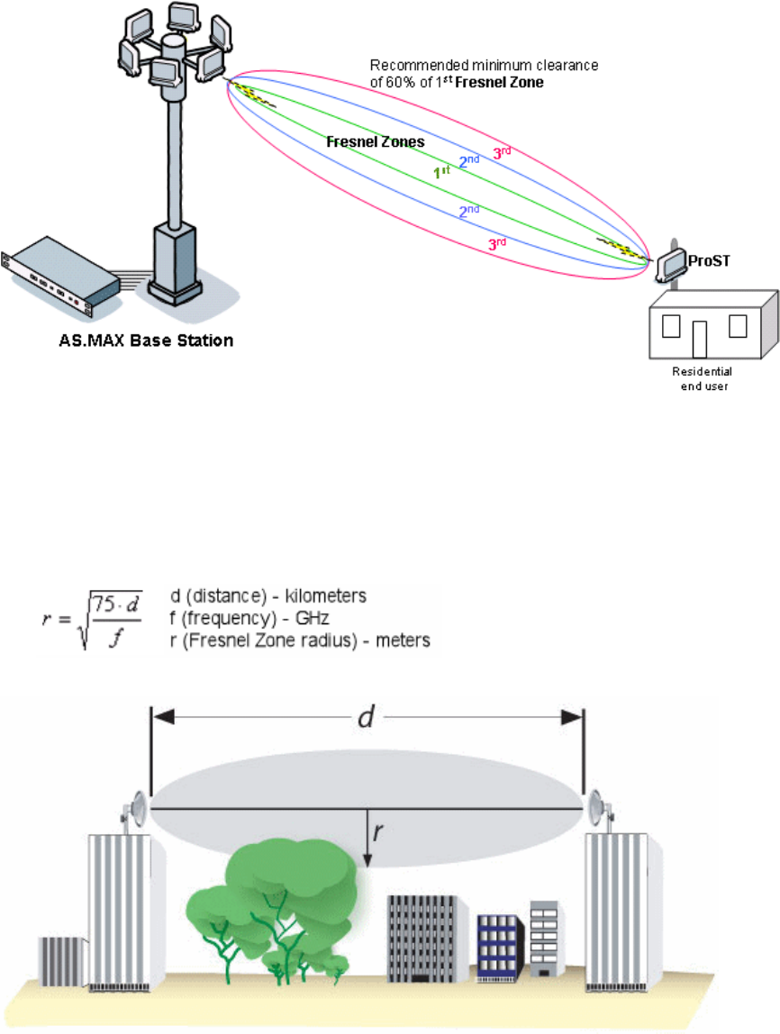
Fresnel Zone Clearance
There must be sufficient open space around the radio path to minimize blocking of the radio
beam. A minimum of 60% of the first Fresnel Zone of the path should be clear of obstructions.
Despite a clear line-of-sight, objects close enough to the transmission path may cause
attenuation in signal strength and an increase in signal interference. Objects with reflective
surfaces that seem relatively far away, may still encroach on the Fresnel Zone, and cause
interference.
605-0000-706 ProST Installation User Guide-Rev H
20
Fresnel Zones define the amount of clearance required from obstacles. These zones are
composed of concentric ellipsoid areas surrounding the straight-line path between two
antennas. Thus, the zone affects objects to the side of the path and those directly in the path.
The first Fresnel Zone is the surface containing every point for which the distance from the
transmitter to any reflection point on the surface point and then onto the receiver is one-half
wavelength longer than the direct signal path.
One method for clearing the Fresnel Zone is by increasing the antenna height.
The first Fresnel Zone radius is calculated by the following equation:
Typically, at least 60% clearance of the first Fresnel Zone is considered as LOS. To ensure the
ground does not enter into the first Fresnel Zone, both antennas (i.e. at Base Station and
subscriber) must be mounted at least 0.6 x r meters above ground level (or clutter level).
Examples, using the formula above,

Installation Prerequisites
21
For a link of 4 km, at 3.5 GHz produces a first Fresnel Zone radius clearance of about 9.3
meters, meaning the antennas should be mounted at a height of at least 5.6 meters (60%
of 9.3 meters) above ground level (or clutter level).
For a link of 4 km, at 4.9 GHz produces a first Fresnel Zone radius clearance of about 7.8
meters, meaning the antennas should be mounted at a height of at least 4.7 meters (60%
of 7.8 meters) above ground level (or clutter level).
Multipath Fading
Some of the transmitted signals may be reflected from a nearby building, by water under the
signal path, or from any other reflectors. This reflected ("bounced") signal can then be received
by the radio receiving the signal and superimposed on the main received signal, thereby
degrading the signal strength.
To avoid multipath fading from nearby buildings etc., Airspan recommends installing the
outdoor radios at the rear end of the buildings instead of at the front. When you install at the
rear end of the building, the front-end of the building blocks incoming signals from multipath
reflections.
Radio Antenna Alignment
Once the ProST is installed and aimed in the general direction of the base station, it is
recommended to measure the received signal strength (RSS) to determine the signal strength
received from the base station, and to precisely align the ProST for maximum signal strength.
You need to orientate (up/down, left/right) the ProST until the maximum RSSI levels are
achieved, and then secure the ProST. For viewing RSS values, see "Web-based Management"
for standard alignment, for finer alignment, see RSSI LED Plug Adapter.
22
PHYSICAL DESCRIPTION
This section provides a description of the components of the ProST installation:
ProST radio (outdoor unit)
SDA-1 adapter (indoor unit -- switch and power interface)
SDA-4S Type II and SDA-4S/VL Type II adapters (optional)
SDA-4SDC Type II (indoor DC unit) (optional)
ProST Physical Description
The ProST is an encased outdoor radio providing access to communication ports on its bottom
panel. The ProST's back panel provides holes for ProST mounting.
This subsection provides the following ProST physical descriptions:
Dimensions
Ports
Physical Dimensions
The table below lists the physical dimensions of the ProST.
Parameter Value
Dimensions (H x W x D) 311 x 244 x 65.5 mm (12.24 x 9.6 x 2.57
inches)
Weight 1.94 kg (approximate)
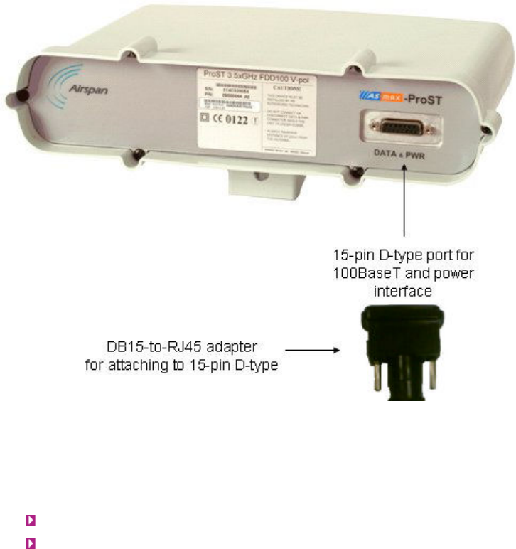
Port
The ProST provides a 15-pin D-type port for interfacing with the SDA-1. For convenience, a
DB15-to-RJ45 adapter is supplied for attaching to the 15-pin D-type port to allow the use of RJ-
45 connectors for outdoor-to-indoor CAT 5 connectivity.
For ProST models implementing third-party external antennas, an N-type port is also provided
on the bottom panel.
Physical Description
23
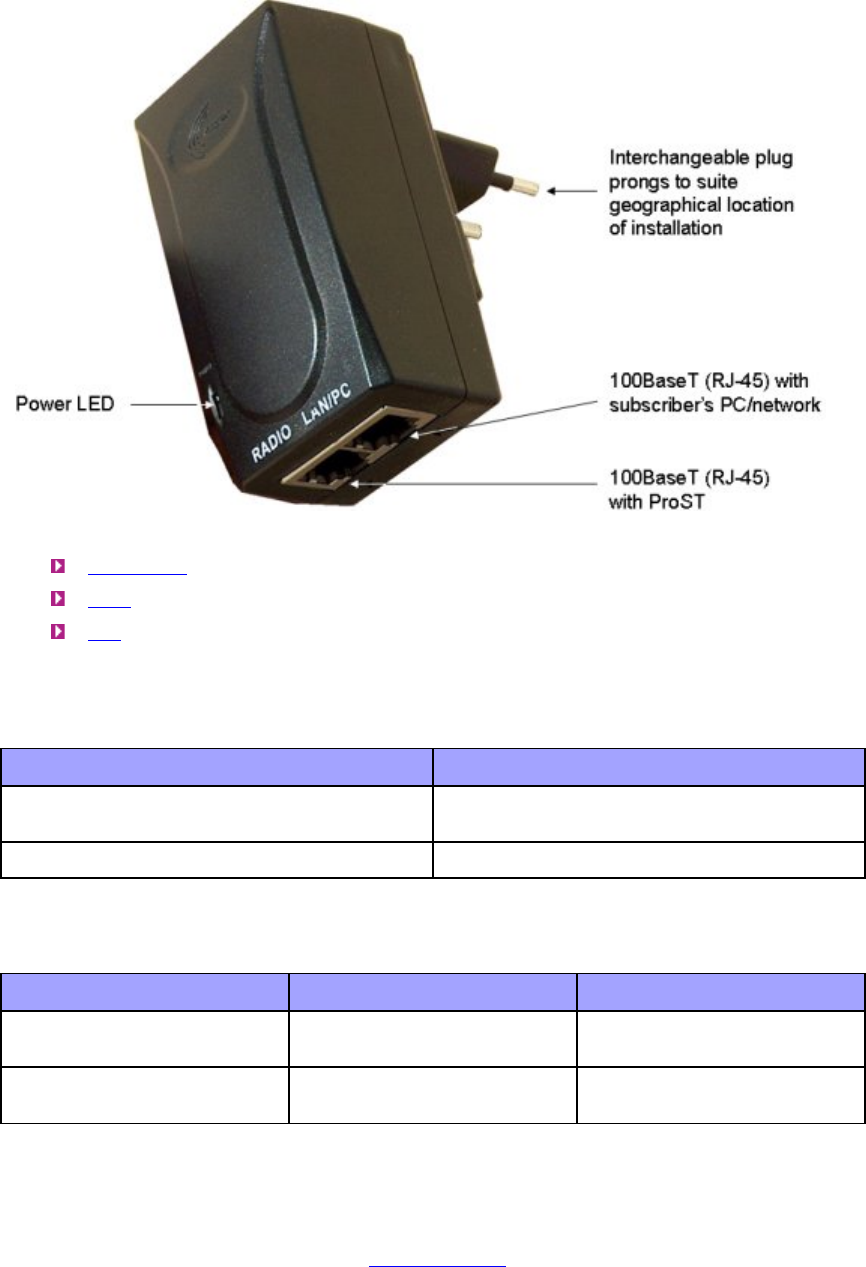
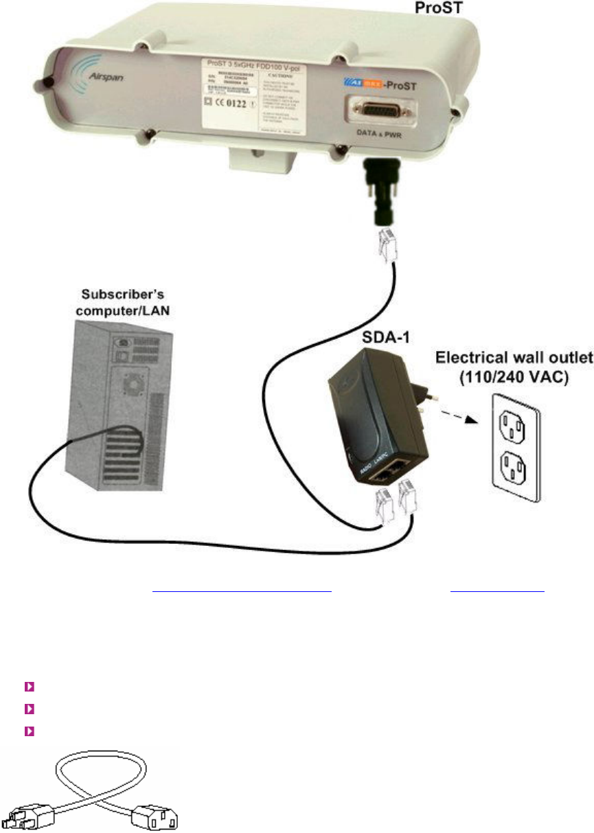
SDA-1 Physical Description
The SDA-1 is an integrated Ethernet and AC/DC power supply adapter that simply plugs into a
standard electrical wall outlet (110/240 VAC). The SDA-1 enables easy plug prong replacement to
suit geographical location of electrical outlet sockets (e.g. American vs. European).
The SDA-1 provides the ProST with the following interfaces:
10/100BaseT interface with subscriber's network/PC
10 to 52 VDC power supply
The SDA-1 physical description is shown in the figure below:
605-0000-706 ProST Installation User Guide-Rev H
24
This section provides the following SDA-1 physical descriptions:
Dimensions
Ports
LED
Physical Dimensions
The SDA-1 physical dimensions are described in the table below:
Parameter Value
Dimensions (L x W x H) 72 x 42.5 x 26 mm (2.83 x 1.67 x 1.02
inches)
Weight 0.159 kg
Ports
The SDA-1 provides two ports, as described in the table below:
Port Label Interface
8-pin RJ-45 RADIO 10/100BaseT with ProST
radio
8-pin RJ-45 LAN/PC 10/100BaseT with
subscriber's network
LED
The SDA-1 provides a green power LED (labeled POWER), located on its front panel. This LED
light not only indicates the presence of power, but also can indicate incorrect SDA-1 port
assignment for the network cables, i.e. from the ProST and computer. For a detailed
description of the POWER LED, see Troubleshooting.
Physical Description
25
Note: The SDA-4S Type II and the SDA-4SDC are physically (externally) the same other
than the power socket.
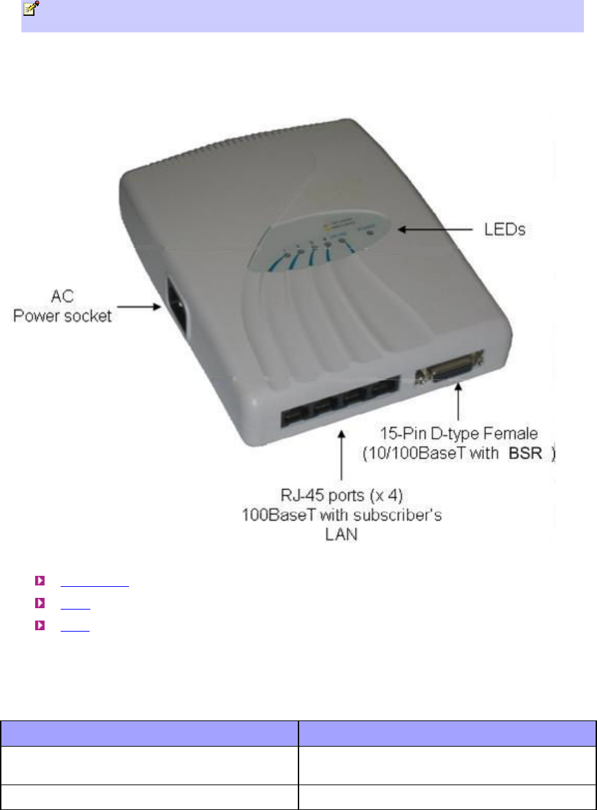
SDA-4S Type II and SDA-4S/VL Type II (Optional)
The SDA-4S Type II and SDA-4S/VL Type II indoor units (hereafter referred to as SDA-4S) are two
optional integrated LAN switches that offer an alternative to the SDA-1 Type II unit. These two units
have identical physical dimensions and design, as displayed in the figure below.
This subsection provides the following SDA-4S physical descriptions:
Dimensions
Ports
LEDs
Physical Dimensions
The SDA-4S Type II and SDA-4S/VL Type II physical dimensions are described in the table
below:
Parameter Value
Dimensions (L x W x H) 200 x 150 x 40 mm (7.87 x 5.9 x 1.57
inches)
Weight 0.577 kg

605-0000-706 ProST Installation User Guide-Rev H
26
Ports
The SDA-4S Type II and SDA-4S/VL Type II adapters provide ports on their bottom panels,
which are described in the table below:
Port Interface
4 x 8-pin RJ-45 10/100BaseT with subscriber's network
(supports Auto Negotiation and MDI/MDI-X
automatic crossover, allowing connection of
straight-through or crossover cables)
15-pin D-type (female) 10/100BaseT with ProST
AC power socket Subscriber's power outlet (110/240 VAC,
50/60 Hz)
Note: The ports of the SDA-4S models support Auto Negotiation, allowing automatic
configuration for the highest possible speed link (10BaseT or 100BaseT), and Full Duplex or
Half Duplex mode. In other words, the speed of the connected device (e.g. PC) determines
the speed at which packets are transmitted through the specific SDA-4S port. For example, if
the device to which the port is connected is running at 100 Mbps, the port connection will
transmit packets at 100 Mbps. Conversely, if the device to which the port is connected is
running at 10 Mbps, the port connection will transmit packets at 10 Mbps.
In addition, the SDA-4S ports support MDI/MDI-X automatic crossover, allowing connection to
straight-through or crossover cables.
LEDs
The LEDs description for all SDA-4S types is the same as for the SDA-4SDC below.
Physical Description
27
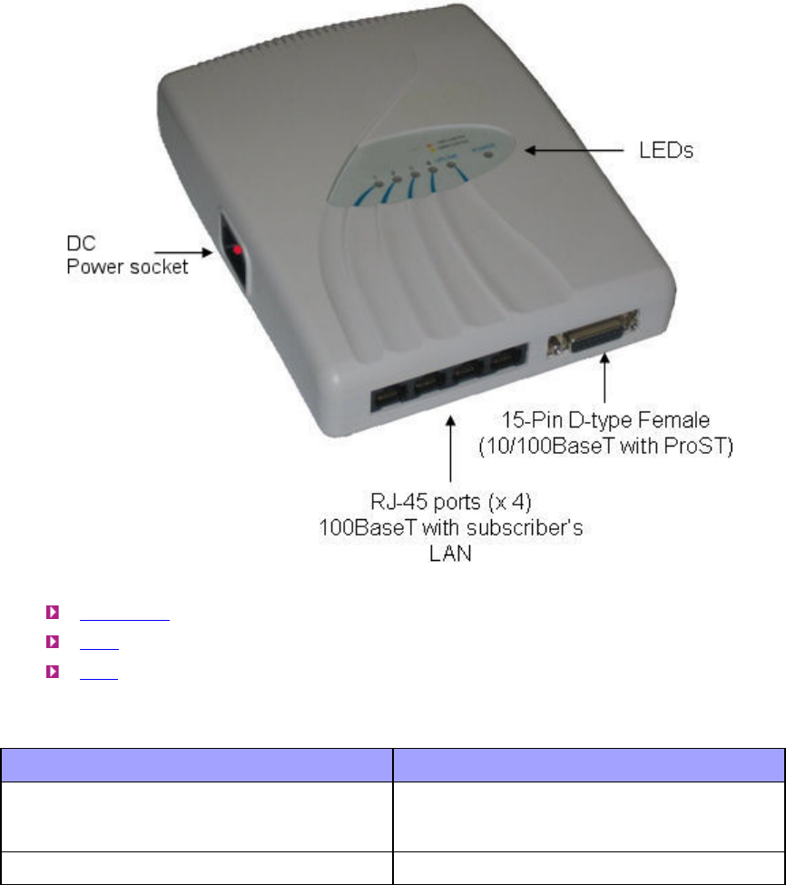
SDA-4SDC Type II (Optional DC power supply)
The SDA-4SDC Type II indoor unit is an integrated LAN switch, providing power and four
10/100BaseT ports for interfacing with the subscriber’s network and especially designed for
implementation where available power supply is DC. This model provides regulated –48 VDC
power. The unit is displayed in the figure below.
This subsection provides the following SDA-4SDC physical descriptions:
Dimensions
Ports
LEDs
Physical Dimensions
The SDA-4SDC physical dimensions are described in the table below:
Parameter Value
Dimensions Height - 200mm (7.87 inches)
Width - 150mm (5.9 inches)
Depth - 40mm (1.57 inches)
Weight 0.53 Kg

605-0000-706 ProST Installation User Guide-Rev H
28
Ports
The SDA-4SDC adapter provides ports on the front panel, which are described in the table
below:
Port Interface
4 x 8-pin RJ-45 10/100BaseT with subscriber's network
(supports Auto Negotiation and MDI/MDI-X
automatic crossover, allowing connection of
straight-through or crossover cables)
15-pin D-type (female) 10/100BaseT with BSR
DC power socket DC power outlet (10-52 VDC, 24W)
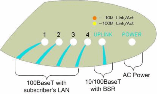
LEDs
The SDA-4S (all Types) adapters (referred conveniently as SDA-4S) provide LED indicators on
their top panels, which are described in the table below:
LED Color Status Meaning
On Physical link (10BaseT
or 100BaseT) between
SDA-4S adapter and
ProST
Blinking Traffic currently
flowing between SDA-
4S and ProST
UPLINK Yellow (100BaseT) or
Orange (10BaseT)
Off No link between SDA-
4S and ProST
On Physical link (10BaseT
or 100BaseT) between
SDA-4S and
subscriber's Ethernet
network
Blinking Traffic currently
flowing between SDA-
4S and subscriber's
Ethernet network
1, 2, 3, 4 Yellow (100BaseT) or
Orange (10BaseT)
Off No link between SDA-
4S and subscriber's
Ethernet network
On Power received by
SDA-4S
POWER Green
Off No power received by
SDA-4S
Physical Description
29
The figure below displays the LEDs which are located on the top panel of the SDA-4S Type II and
SDA-4S/VL Type II adapters:
30
MOUNTING THE PROST
This section describes the mounting procedures for the ProST and the optional SDA-4S adapters.
Mounting the ProST
Warning: ProST is an outdoor radio unit and therefore, must only be mounted
outdoors.
Warning: Mount the ProST in an orientation such that its 15-pin D-type port (located
on the bottom panel) faces downwards. This prevents rain water from settling on the port,
and thereby, avoiding damage to the unit such as corrosion and electrical short-circuiting.
The ProST offers two optional methods for outdoor mounting:
Wall mounting
Pole mounting
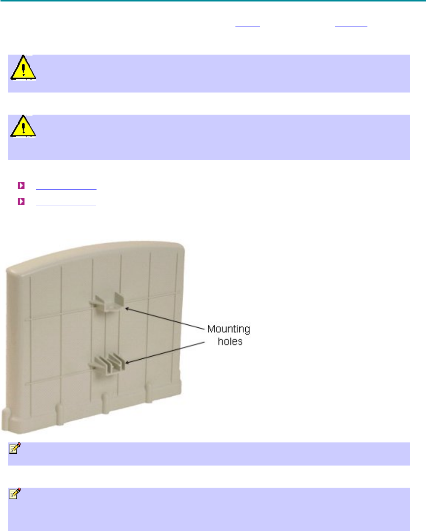
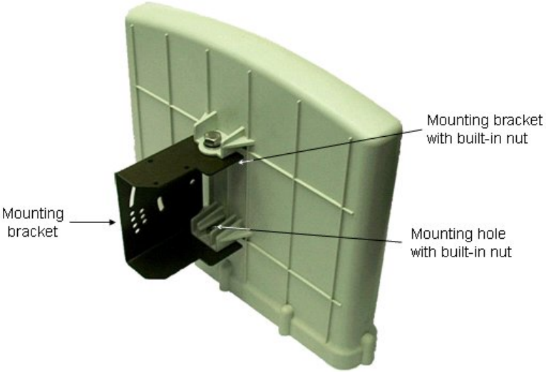
For either mounting methods, the ProST provides mounting holes molded into its back panel for
attaching the wall or pole-mounting brackets, as displayed in the figure below.
Note: The standard ProST kit provides wall-mounting brackets. To pole mount the ProST,
contact your nearest Airspan distributor for pricing and ordering of pole-mounting brackets.
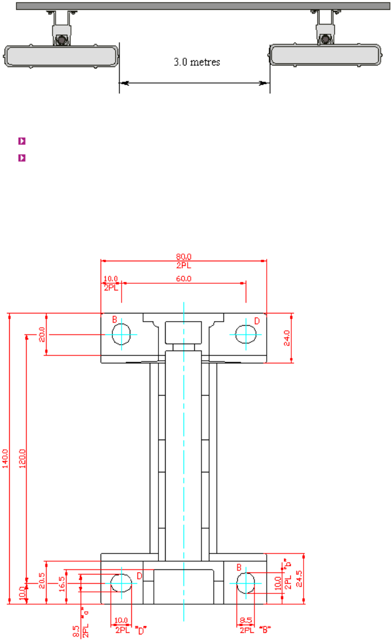
Note: A minimum of 3-meter separation is required between mounted ProSTs and existing
customer radio equipment when transmitting on different sectors (see figure below).
However, only a 1-meter separation is required between ProSTs when on the same sector and
transmitting to the same base station radio without requiring shielding.
The figure below illustrates the minimum separation between mounted ProST's when transmitting
on different sectors:
Mounting the ProST
31
Wall Mounting
The ProST is wall mounted in two main stages:
Attaching the mounting bracket to the ProST's mounting holes
Attaching the mounting bracket (attached to the ProST) to the wall
To wall mount the ProST:
1. Position the unassembled mounting bracket on the mounting surface (e.g. wall), and then
use a pencil to mark the position of the four mounting holes. Ensure that the distance
between the hole centers are 120 mm (height) and 60 mm (width), as displayed in the
figure below showing the ProST's fixing dimensions.
2. Drill holes for each hole that you marked in the step above.
605-0000-706 ProST Installation User Guide-Rev H
32
3. Insert wall anchors (not supplied) into each of the drilled holes.
4. Align the mounting bracket's four holes with the wall anchors, and then insert a screw (not
supplied) through the mounting bracket holes into each wall anchor, and tighten.
Note: Airspan does not provide screws for attaching the mounting bracket to the wall. The
screw size depends on the structure of the building to which the bracket is to be attached.
When selecting screw sizes, consideration must be given to the weight of the ProST and load
that may be induced in windy conditions.
5. Attach the ProST to the mounting bracket by performing the following:
a. Slide an M10-spring lock washer and then an M10-plain washer onto each M10-hex
head screw (ensure lock washer is nearest to head of screw bolt).
b. Align the mounting bracket's holes with the ProST's mounting holes as displayed below.
(The mounting bracket side that provides a groove for inserting a nut must be aligned
with the ProST's mounting hole that is nearest to the ProST's rear panel.)
c. From the external sides, insert the M10-hex head screws through the mounting
bracket's holes and ProST's mounting holes. Loosely fasten with the M10-hex nuts.
Mounting the ProST
33
6. Adjust the horizontal positioning of the ProST, and then tighten the two M10-hex head
screws with the M10 hex nuts.
Note: A third-party thread-locking compound must be applied to the M10-hex head screws
to prevent the bolts from working loose.
Rotation is restricted in the horizontal plane only, as shown in the figure below:
Pole Mounting
Pole mounting allows the ProST to be easily adjusted in the horizontal (azimuth) and vertical
(elevation) planes for antenna alignment. The ProST is mounted using the mounting holes located
605-0000-706 ProST Installation User Guide-Rev H
34
on the ProST's back panel and the supplied (when ordered) pole-mounting brackets. The pole-
mounting bracket is designed to support the ProST on a round pole of 45 mm in diameter.
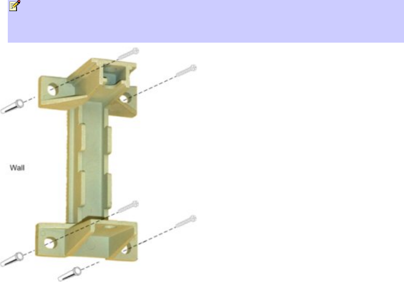
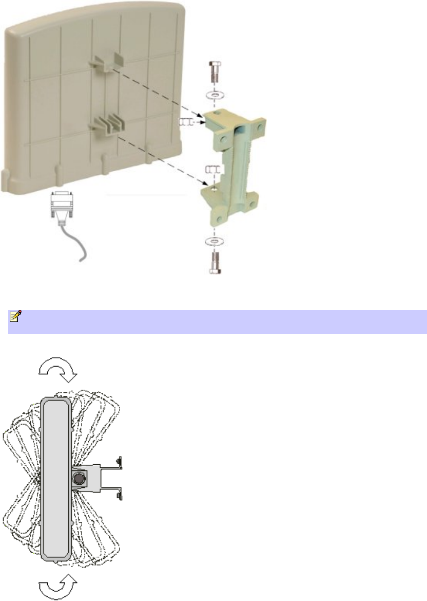
The figure below illustrates a summary of the ProST pole-mounting procedure.
To pole mount the ProST:
1. Attach the mounting bracket to the ProST:
a. Align the mounting bracket with the ProST's mounting holes so that the mounting
bracket's side with the built-in nut is aligned with the ProST's mounting holes furthest
from the ProST's bottom panel, as shown in the figure below.
b. Slide an M10-flat washer and M10-spring lock washer onto an M10-hex head screw
(ensure spring lock washer is closest to the bolt's head). From the external side, insert
the M10-hex head screw through the mounting bracket and ProST's mounting holes.
Fasten the M10-hex head screw (one is provided with a built-in nut while the other
requires you to insert an M10-hex nut into the ProST's mounting hole).
Mounting the ProST
35
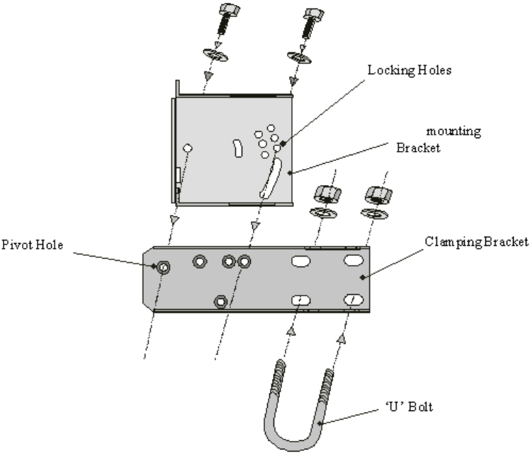
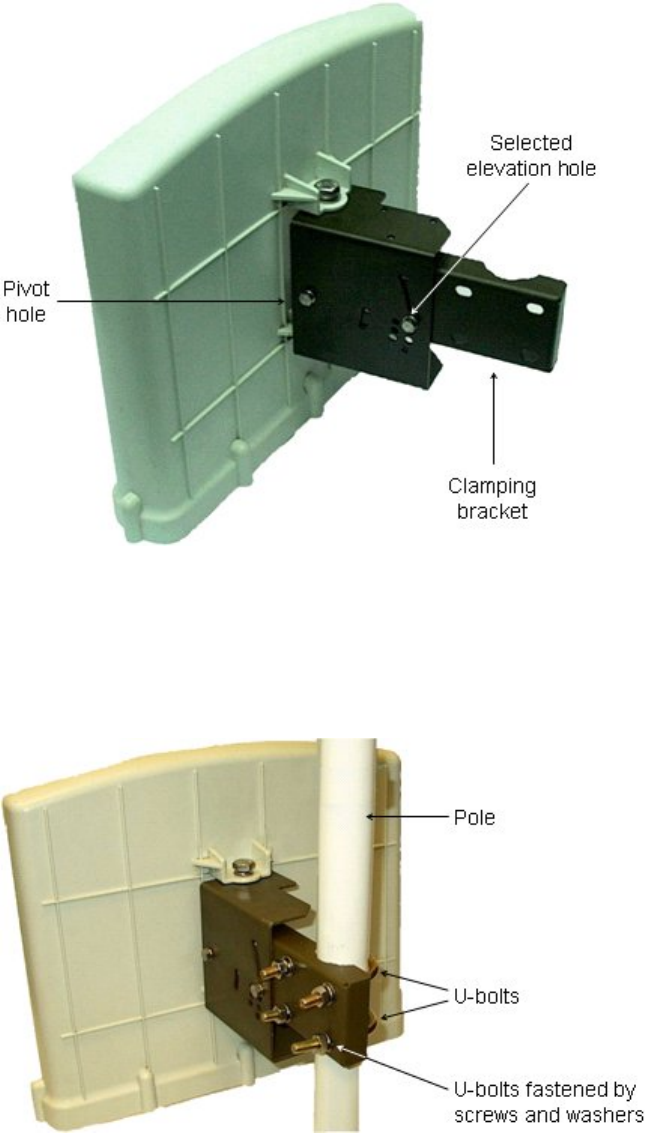
2. Attach the clamping bracket to the mounting bracket:
a. Slide an M6-spring lock washer onto an M6-hex head screw. Align the mounting
bracket's and clamping bracket's pivot holes, such that the clamping bracket is aligned
to the inside of the mounting bracket. From the external side of the mounting bracket,
insert the M6-hex head screw into the pivot holes and then fasten, but not tightly. (The
clamping bracket provides a built-in nut.)
b. Choose an elevation hole on the mounting bracket and then align it with the
corresponding hole on the clamping bracket. Slide an M6-spring lock washer onto an
M6-hex head screw, and then from the external side of the mounting bracket, insert
the M6-hex head screw through the elevation hole on the mounting bracket and into
the clamping bracket's corresponding hole. Fasten but not tightly the M6-hex head
screw (the clamping bracket provides built-in nut). The elevation hole can later be
changed according to desired antenna orientation in the elevation plane.
605-0000-706 ProST Installation User Guide-Rev H
36
3. Attach the U-bolt to the pole:
a. Place one U-bolt around the pole, and then insert the U-bolt screw side through the
two corresponding holes (horizontally parallel) on the clamping bracket. Slide an M8-
flat washer and M8-spring lock washer onto each U-bolt screw side (ensure that the flat
washer is adjacent to the clamping bracket). Fasten each U-bolt side with the two M8-
hex nuts.
b. Attach the second U-bolt as described above.
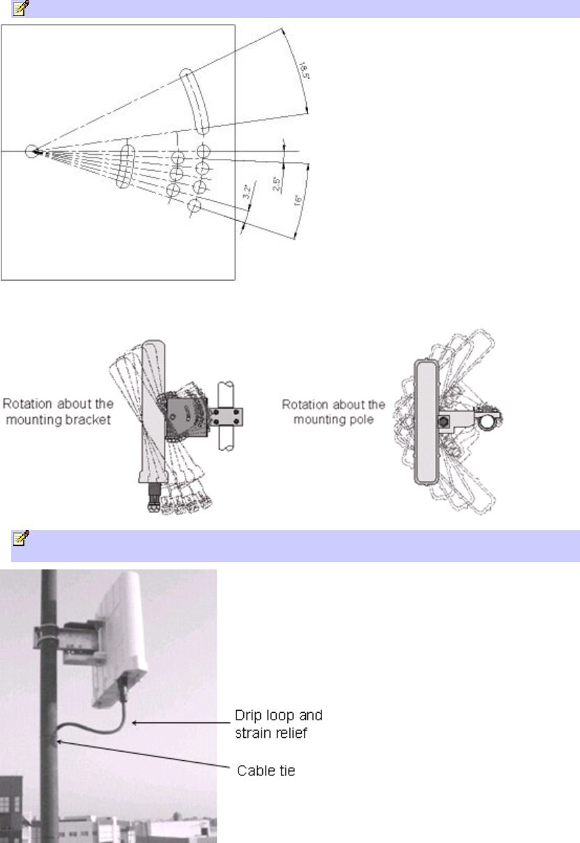
4. Perform final ProST orientation:
a. Adjust the vertical position of the ProST by choosing a final elevation hole as described
in Step 2. Lock the ProST at the desired position by inserting the locking bolt in the
desired position and fastening it tightly. Fasten tightly the bolt in the pivot hole. The
figure below illustrates the angles (in degrees) of each elevation hole. As shown, the
ProST pole-mounting bracket allows elevation between -18.5° and 26.3°.
Mounting the ProST
37
b. Adjust the horizontal position of the ProST by rotating it about the pole, and then
tightening the nuts of the U-bolts.
Note: A thread-locking compound must be used to prevent the bolts from working loose.
ProST positioning is obtained in two planes by adjustment of the mounting bracket assembly as
shown below:
Note: It is important to provide strain relief and drip loop for Cat-5 cables. Create a drip
loop and strain relief using cable tie, to tie cable to pole, as displayed in the figure below.
605-0000-706 ProST Installation User Guide-Rev H
38
SDA-4S
The SDA-4S adapters (all types) can be mounted either horizontally on a desktop or vertically on a
wall.
Desktop Mounting
Desktop mounting is made possible by the existence of four feet, each located on the four corners
of the SDA-4S bottom panel. Therefore, no installation is necessary for desktop mounting.
Warning: To prevent a fire hazard caused by overheating, do not place the SDA-4S on
a carpeted surface where airflow is restricted.
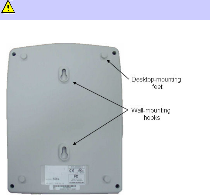
Wall Mounting
Wall mounting is made possible by the existence of two mounting hooks molded into the SDA-
4S's bottom panel, as displayed in the figure below.
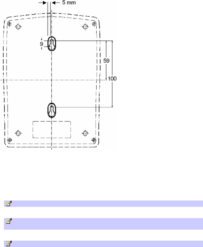
To wall mount the SDA:
1. On the wall, mark the position of the two mounting hooks. The dimensions of the wall-
mounting hooks are displayed in the template below.
Mounting the ProST
39
2. Drill holes for each hole that you marked in the step above.
3. Insert wall anchors (supplied) into each of the drilled holes.
4. Insert the 9-inch screws (supplied) into the wall anchors. Ensure at least 2 mm of the screw
is exposed to allow insertion into the SDA-4S mounting holes.
5. Hold the SDA-4S with both hands, and align the entrance to the two mounting hooks with
the screws. Slide the screws into the mounting hooks, by lowering the SDA-4S onto the
screws.
Note: For safety, use both mounting hooks to mount the unit.
Note: The SDA-4S is supplied with a 1 meter AC power lead assembly. Ensure the unit
is mounted within 1 meter of the main power outlet.
Note: The maximum cable run between SDA-4S and ProST is 100 meters.
40
NETWORK CABLING
ProST interfaces with the subscriber's network through the IDU (i.e. typically the SDA-1 Type II, or
optionally through the SDA-4S Type II, SDA-4S/VL Type II or SDA-4S/DC). The ProST also receives
DC power from the IDU.
This section describes the ProST network cabling:
Connecting ProST to IDU
Connecting IDU to a Computer
Connecting to IDU
The ProST typically interfaces with the subscriber's network using the indoor SDA-1 Type II adapter.
However, optional IDU adapters (SDA-4S Type II, SDA-4S/VL Type II or SDA-4S/DC) are offered
that provide multiple LAN ports for interfacing with the subscriber's network.
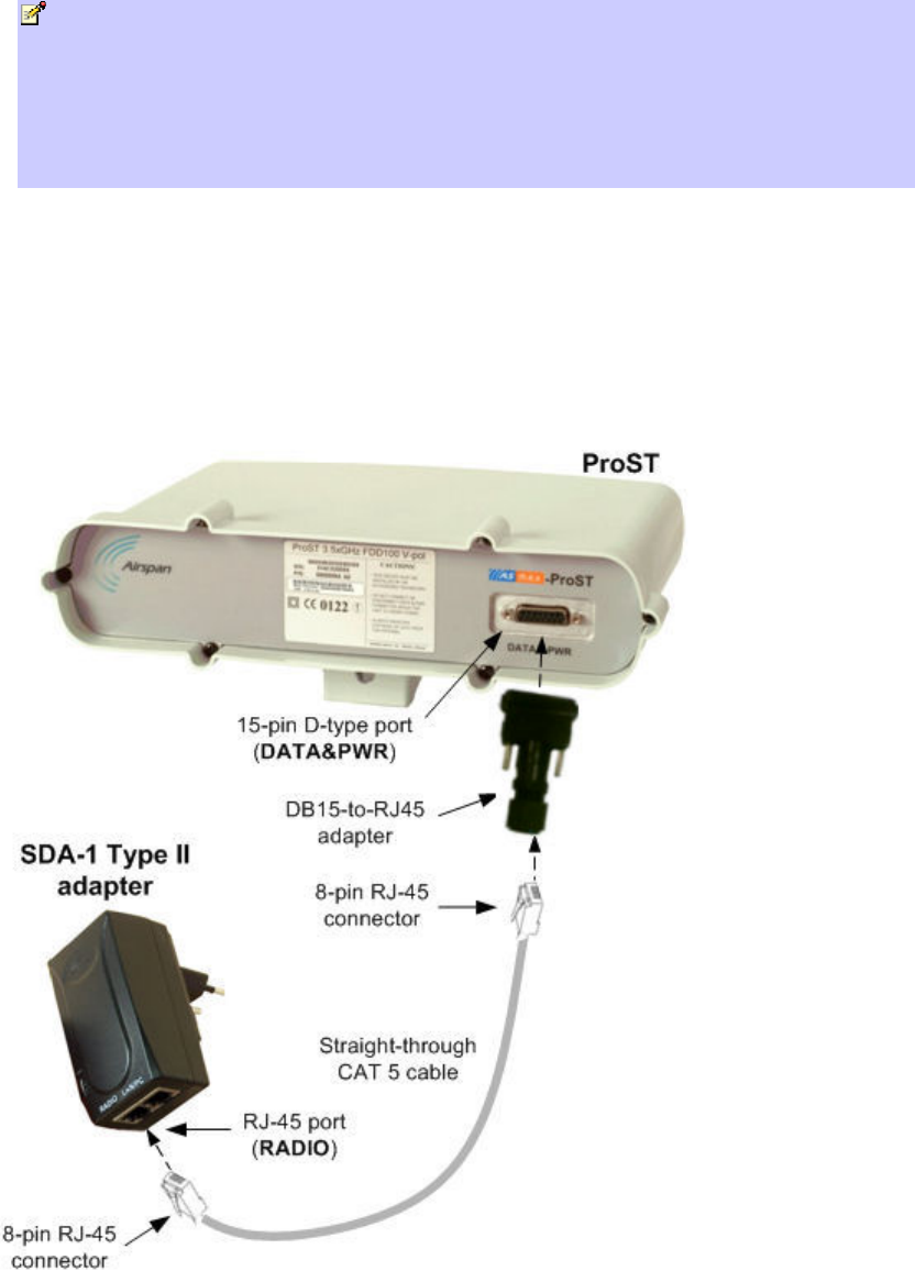
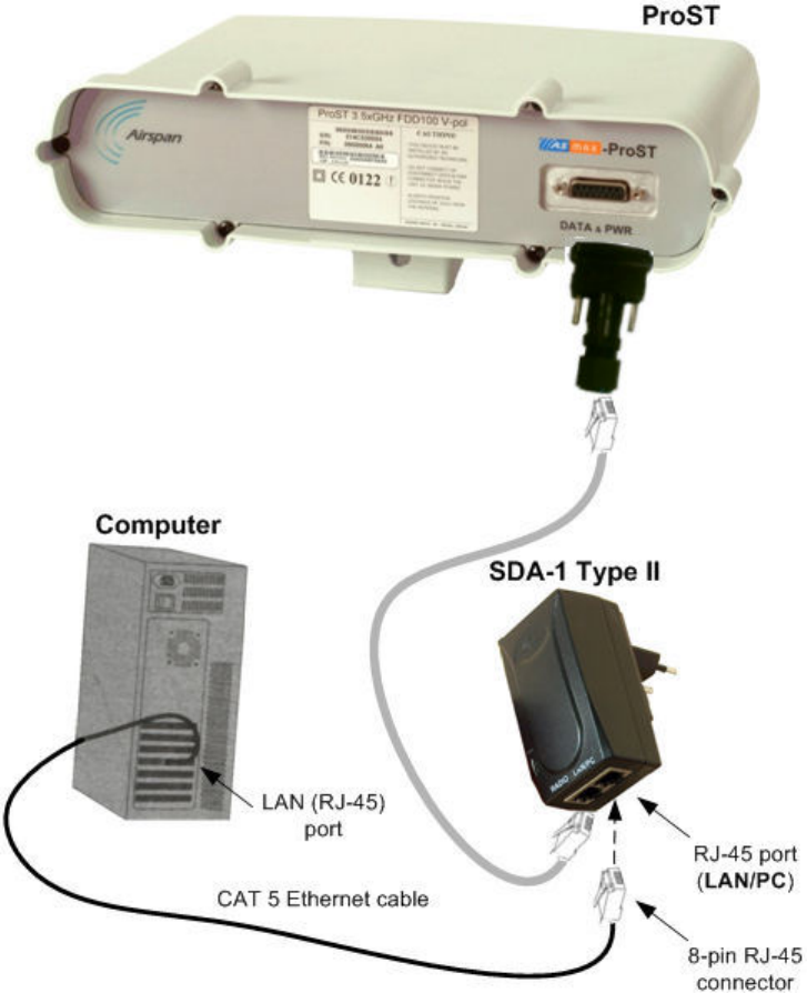
Using the SDA-1 Type II
The ProST connects to the SDA-1 using a CAT 5 cable with 8-pin RJ-45 connectors on either
end. The ProST provides a 15-pin D-type port for interfacing with the SDA-1. However, for
allowing the use of RJ-45 connectors, your ProST kit includes a DB15-to-RJ45 adapter that can
easily be attached to the ProST's 15-pin D-type port.
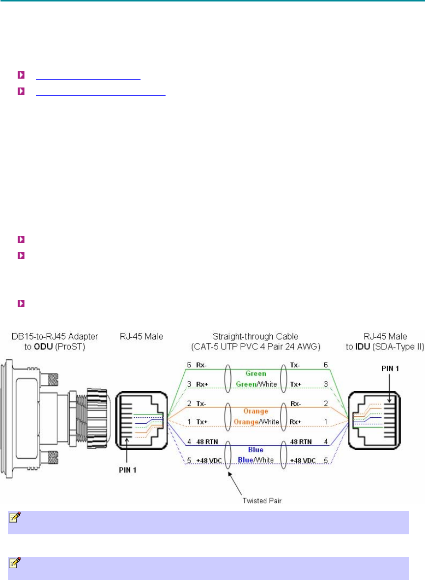
The cable setup for ProST-to-SDA-1 connectivity is as follows:
Cable: Straight-through CAT 5 Ethernet cable
Connectors:
o ProST: DB15-to-RJ45 adapter
o CAT 5 cable with 8-pin RJ-45 male connectors on either end
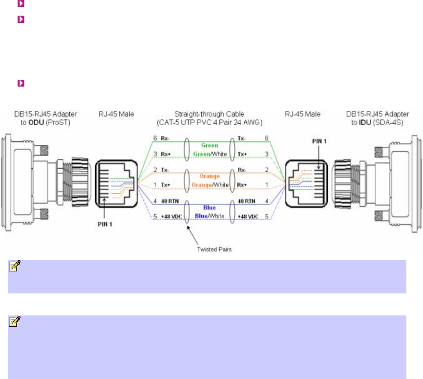
Connector pinouts:
Note: The SDA-1 Type II is protected in the event power is inadvertently inserted to the
radio port so as not to damage the Ethernet card.
Note: A DB15-to-RJ45 adapter for plugging into the ProST's 15-pin D-type port (with pins
7 & 8 not connected) is included, replacing previous adapter.
Network Cabling
41
Notes:
• Only pins 1 to 6 are used.
• Pins 7 and 8 must not be wired to the ProST end.
• The wire color-coding described in the table is Airspan's standard for wire color-coding.
However, if you implement your company's wire color-coding scheme, ensure that the wires
are paired and twisted according to pin functions listed in the table above (e.g. Rx+ with Rx-
).
• The maximum CAT 5 cable length for ODU/IDU connectivity is 100 meters.
To connect the ProST to the SDA-1:
1. Attach the DB15 side of the DB15-to-RJ45 adapter to the ProST's 15-pin D-type port
(female), labeled DATA & PWR.
2. Plug the RJ-45 connector of the Category 5 Ethernet cable (not supplied) into the RJ-45
port of the DB15-to-RJ45 adapter.
3. Plug the RJ-45 connector, at the other end of the Category 5 Ethernet cable, into the SDA-
1's RJ-45 port labeled RADIO.
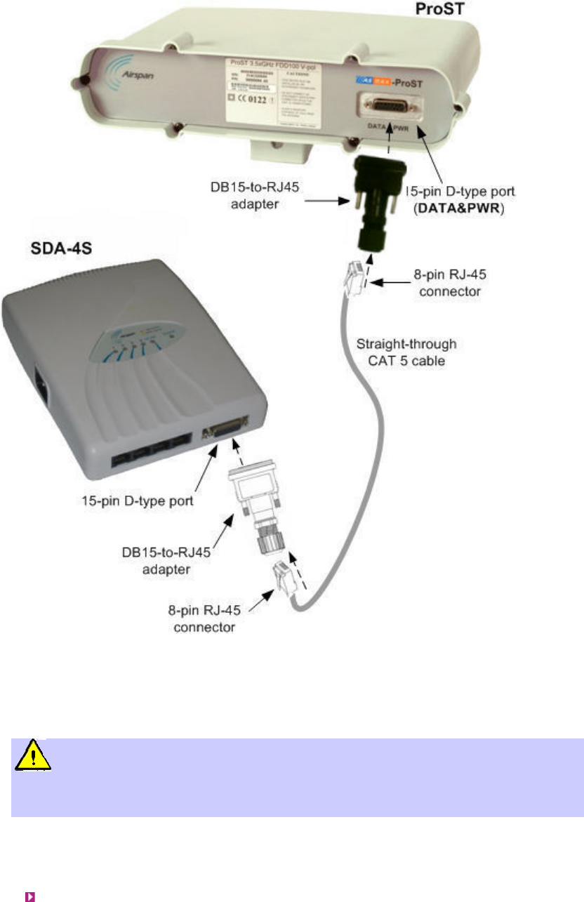
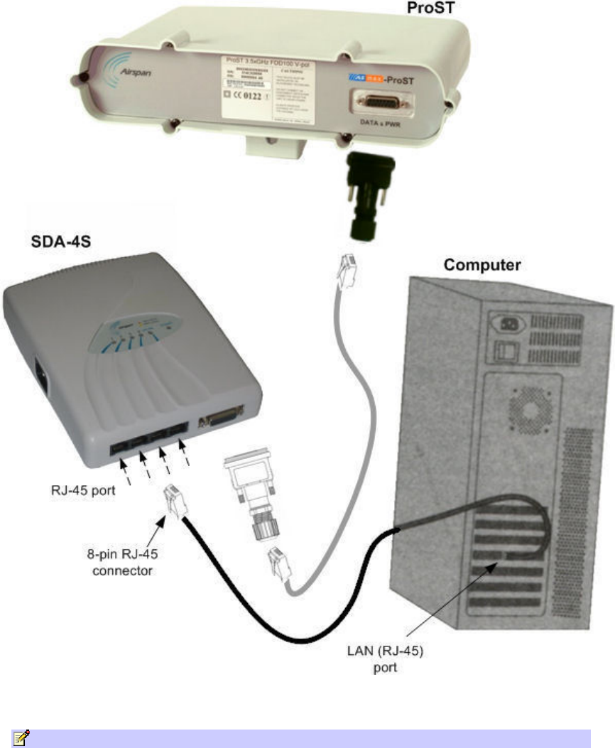
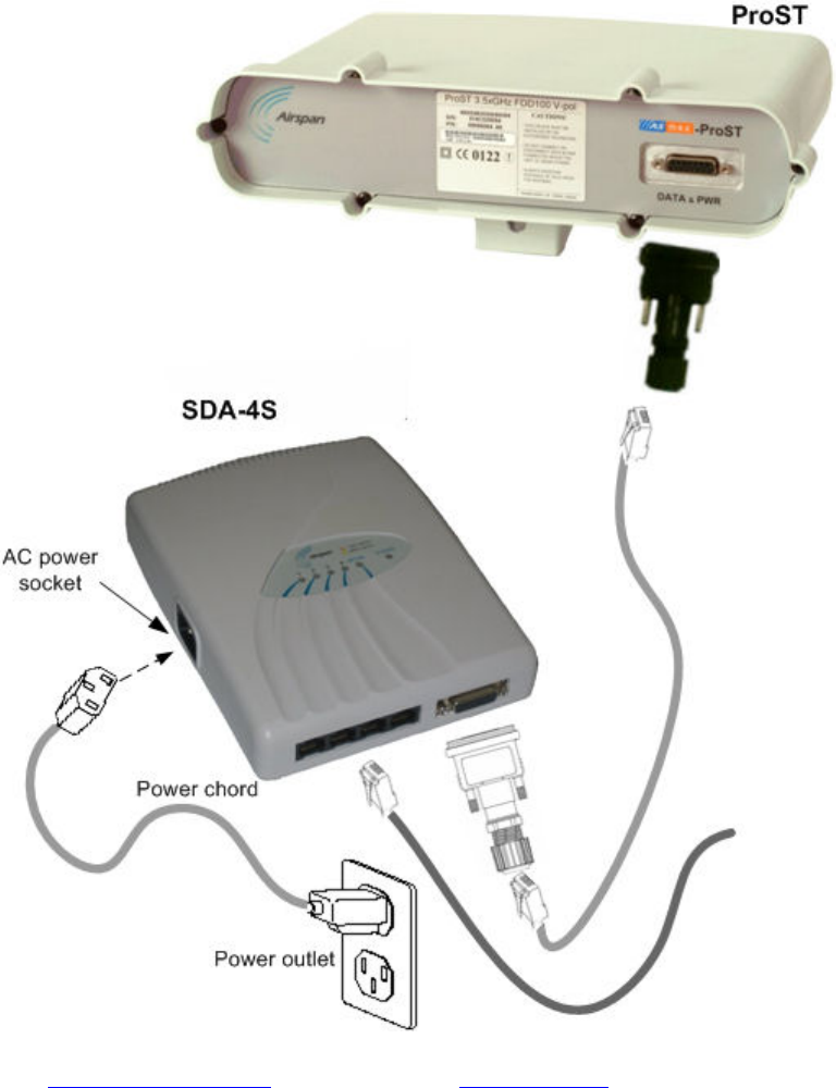
Using the SDA-4S Type II, SDA-4S/VL Type II or SDA-4S/DC Type II
The SDA-4S Type II, SDA-4S/VL Type II or SDA-4S/DC Type II adapters (referred hereafter as
SDA-4S) provide one 15-pin D-type female port for interfacing with the ProST (which also
provides a 15-pin D-type female port).
605-0000-706 ProST Installation User Guide-Rev H
42
The ODU-to-IDU connectivity implements a CAT 5 cable with 8-pin RJ-45 connectors at either
end. However, for allowing the use of RJ-45 connectors, your ProST kit includes two DB15-to-
RJ45 adapters that can easily be attached to the 15-pin D-type ports of the ProST and SDA-4S.
The cable setup for ProST to SDA-4S connectivity is as follows:
Cable: Straight-through CAT 5 Ethernet cable
Connectors:
o ProST: DB15-to-RJ45 adapter
o SDA-4S: DB15-to-RJ45 adapter
o CAT 5 cable with 8-pin RJ-45 male connectors on either end
Connector pinouts:
Note: The standard ProST/ProST-WiFi kit does not include the SDA-4S Type II, SDA-4S/VL
Type II or SDA-4S/DC adapters. For pricing and ordering of either the SDA-4S Type II, SDA-
4S/VL Type II or SDA-4S/DC adapter, please contact your nearest Airspan dealer.
Notes:
• The wire color-coding described in the table is Airspan's standard for wire color-coding.
However, if you implement your company's wire color-coding scheme, ensure that the wires
are paired and twisted according to pin functions listed in the table above (e.g. Rx+ with Rx-
).
• The maximum CAT 5 cable length for ODU/IDU connectivity is 100 meters.
To connect the ProST to the SDA-4S:
1. Attach the DB15 side of the DB15-to-RJ45 adapter to the ProST's 15-pin D-type port
(female), labeled DATA & PWR.
2. Attach the DB15 side of the second DB15-to-RJ45 adapter to the SDA-4S's 15-pin D-type
port (female).
3. Plug the RJ-45 connector, at one end of the CAT 5 cable (not supplied), into the RJ-45 port
of the DB15-to-RJ45 adapter located at the ProST.
4. Plug the RJ-45 connector, at the other end of the CAT 5 cable, into the RJ-45 port of the
DB15-to-RJ45 adapter located at the SDA-4S.
Network Cabling
43
Connecting to LAN Network
The ProST typically interfaces with the subscriber's LAN network using the indoor SDA-1 Type II
adapter. This adapter provides one 100BaseT interface. However, optional IDU adapters (SDA-4S
Type II, SDA-4S/VL Type II or SDA-4S/DC Type II) are offered that provide four LAN ports for
interfacing with the subscriber's LAN network.
Warning: Only subscriber terminal equipment (e.g. computer modem port) that is
designed for full compliance with TNV-1 telecommunication network connectivity can be
connected to the SDA-1. Warranty of Airspan's equipment shall be made void if the SDA-1 is
connected to a computer that is not compliant with TNV-1.
Using SDA-1 Type II
The SDA-1 Type II provides a single 100BaseT interface with the subscriber's LAN network.
The cable setup for SDA-1 Type II connectivity is as follows:
Cable: Straight-through CAT 5 Ethernet cable
605-0000-706 ProST Installation User Guide-Rev H
44
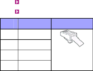
Connectors: 8-pin RJ-45
Connector pinouts:
Pin Function 8-Pin RJ-45
1 Tx+
2 Tx-
3 Rx+
6 Rx-
To connect the ProST to the subscriber's network/PC (via SDA-1 Type II):
1. Plug the supplied Category 5 Ethernet cable into the SDA-1's RJ-45 port labeled LAN/PC.
2. Plug the loose end of the Category 5 Ethernet cable into the computer's LAN port.
Network Cabling
45
Using the SDA-4S Type II, SDA-4S/VL Type II or SDA-4S/DC Type II
The SDA-4S Type II, SDA-4S/VL Type II or SDA-4S/DC adapters (referred hereafter as SDA-
4S) provide four RJ-45 (100BaseT) ports for interfacing with the subscriber's LAN network. The
difference between these adapters is that the SDA-4S/VL supports VLAN functionality at the
ports.
The ports of the SDA-4S models support Auto Negotiation, allowing automatic configuration for
the highest possible speed link (10BaseT or 100BaseT), and Full Duplex or Half Duplex mode.
In other words, the speed of the connected device (e.g. PC) determines the speed at which
packets are transmitted through the specific port. For example, if the device to which the port
is connected is running at 100 Mbps, the port connection will transmit packets at 100 Mbps.
Conversely, if the device to which the port is connected is running at 10 Mbps, the port
connection will transmit packets at 10 Mbps
In addition, the SDA-4S ports support MDI/MDI-X automatic crossover, allowing connection to
straight-through or crossover CAT-5 cables. Therefore, these ports can be connected to either a
hub (i.e. using crossover cables) or a PC (i.e. using straight-through cables).
The cable setup for SDA-4S LAN connectivity is as follows:
605-0000-706 ProST Installation User Guide-Rev H
46
Cable: Straight-through (e.g. when connecting to PC) or crossover (i.e. when connecting to
a hub) CAT 5 Ethernet cable
Connectors: 8-pin RJ-45 at both ends
Connector pinouts:
o Straight-through cable (e.g. connecting to a PC)
Pin Function 8-Pin RJ-45
1 Tx+
2 Tx-
3 Rx+
6 Rx-
o Crossover cable (e.g. connecting to a hub)
Pin Function Pin Function 8-Pin RJ-45
1 Rx+ 3 Tx+
2 Rx- 6 Tx-
3 Tx+ 1 Rx+
6 Tx- 2 Rx-
Network Cabling
47
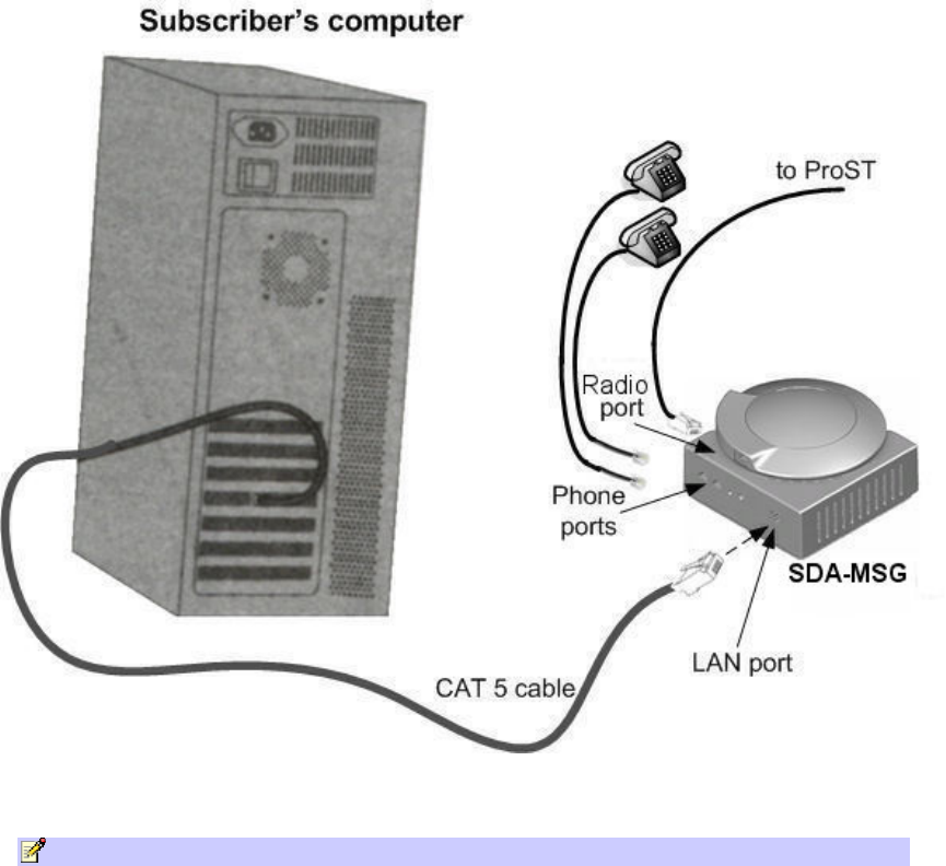
Using SDA-MSG
Optional extension VoIP module enabling VoIP functionality to your ProST units.
Note: For pin-out refer to SDA-1 Type 2 above.
To connect the SDA-MSG’s Radio port to Ethernet network and the RJ 45 port to
ProST:
1. Plug the Category 5 Ethernet cable into the MSG unit 8-pin RJ-45 LAN port.
2. Plug the other end of the Category 5 Ethernet cable into your computer's LAN port located
at the back of your computer.
3. Plug the additional Category 5 Ethernet cable into the other SDA unit 8-pin RJ-45 Radio
port and then into the ProST.
605-0000-706 ProST Installation User Guide-Rev H
48
4. Plug standard telephone cable(s) (with RJ 11 ends) into phone(s) and MSG jack(s).
The figures below illustrate the SDA-MSG-to-computer cable and
SDA-MSG-to-ProST (or ProST-WiFI) cable connection:
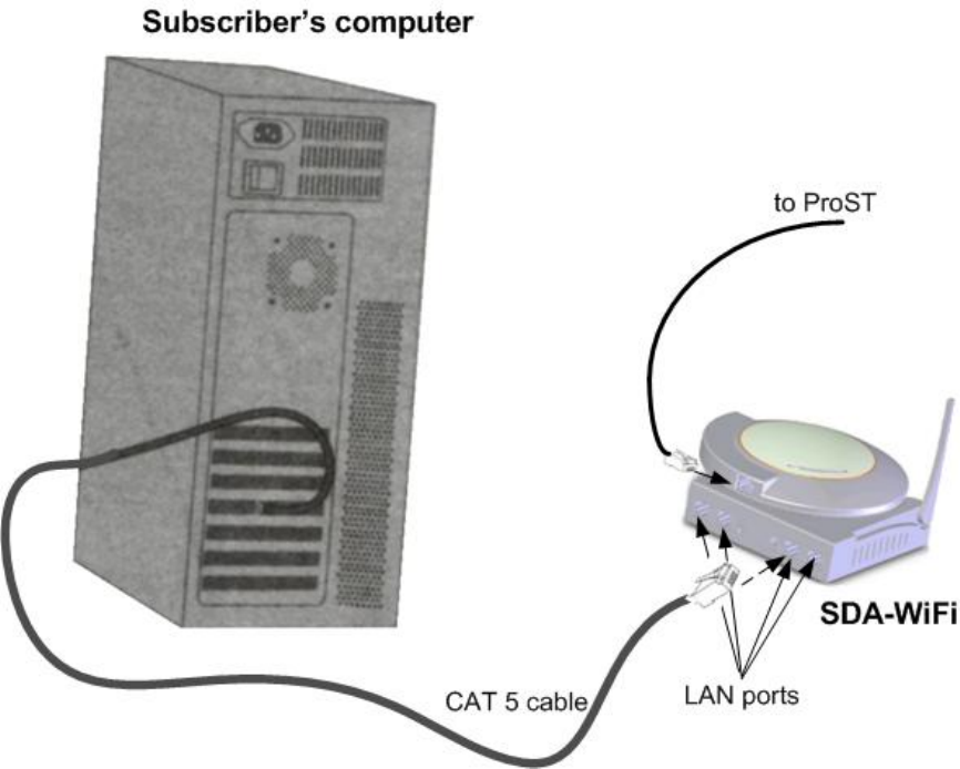
Using SDA-WiFi
Optional extension WiFi module enabling WiFi functionality to your ProST units.
Note: For pin-out refer to SDA-1 Type 2 above.
To connect the SDA-WiFi’s LAN port(s) to Ethernet network and the RJ 45 port to
ProST:
1. Plug a Category 5 Ethernet cable into one or more of the SDA-WiFi unit's 8-pin RJ-45 LAN
ports.
2. Plug the other end of the Category 5 Ethernet cable into a computer's LAN port located at
the back of the computer.
3. Plug the additional Category 5 Ethernet cable into the PSA unit 8-pin RJ-45 Radio port and
then into the ProST.
The figures below illustrate the SDA-WiFi-to-computer cable and
SDA-WiFi-to-ProST cable connection:
Network Cabling
49

50
CONNECTING TO POWER
The ProST is a DC-powered device requiring 48 VDC at 24W max. The ProSt is powered by the SDA-
1 Type II or optionally by the SDA-4S Type II, SDA-4S/VL or the SDA-4S/DC internal integrated
LAN switches connecting to the ProST through the ProST's 15-pin D-type port.
ProST can be powered from one of the following power sources:
DC power: connected directly to a 10 - 52 DC power source
AC power: connected to a standard electrical wall outlet (110/240 VAC) using an AC/DC
power adapter
In addition, Airspan offers an optional third-party outdoor, lightning and surge protector that
protects the ODU-to-IDU CAT 5 cable's power and data signals from any electrical surges due to
lighting strikes.
Note: ProST is designed with a built-in lightning surge protection that complies with the
Surge Immunity standard EN 61000-4-5.
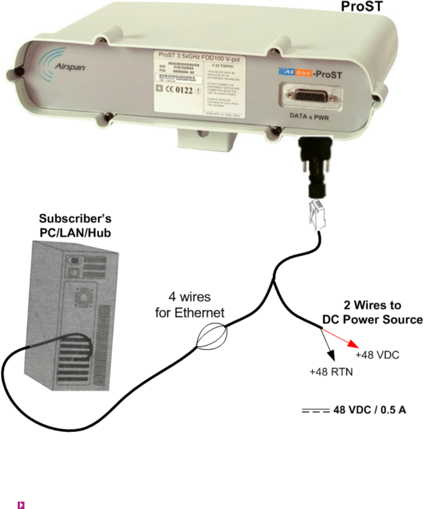
DC Power Source
ProST can be connected directly to a DC power supply unit that supplies 10 – 52 VDC (0.2 to 0.9 A;
15W maximum, assuming up to 100-m cable length between ProST and power source).
The ProST-to-DC power connectivity is supported by a splitter cable. One end of the splitter cable
connects to the ProST (using the RJ45-to-DB15 adapter or connecting directly to the 15-pin D-type
port); the other end of the cable splits into the following two wire groups:
One group for the subscriber's Ethernet interface (four wires for the Tx and Rx signals)
One group for the DC power source interface (two wires for +48 VDC and +48 RTN)
Warning: ProST should be powered by a safety approved Class II limited DC power
source with maximum current of 1A.
The figure below displays the ProST-to-DC power supply cable setup:
Connecting to Power
51
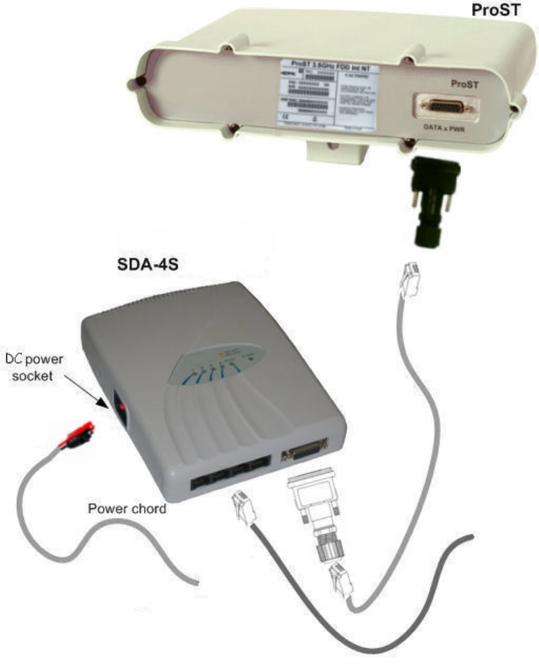
Connecting the SDA-4SDC Type II (Optional DC adapter)
The SDA-4S/DC adapter is connected to the DC power supply using a cable appropriate to the
specific field conditions.
The setup between the SDA-4SDC and power connection includes the following:
Connector: Anderson Connector Housings for connecting the cable to the SDA-4SDC DC
power socket.
o 1327 - Red Housing x 1
o 1327G6 - Black Housing x 1
605-0000-706 ProST Installation User Guide-Rev H
52

Connecting to Power
53
AC Power Source
ProST is powered from an AC power source when implementing the SDA-1 Type II, which is plugged
directly into a standard electrical wall outlet (110/240 VAC). The optional IDU adapters (SDA-4S
Type II and SDA-4S/VL Type II) also power ProST from the subscriber's AC electrical wall outlet.
The difference between the SDA-1 Type II and SDA-4S Type II adapters is the method of
connectivity to the power outlet, as discussed in the subsections below.
Using SDA-1 Type II
The SDA-1 Type II is plugged directly into a standard electrical wall outlet ((110/240 VAC). The
SDA-1 Type II also allows easy plug prongs replacement to suit the electrical wall socket (e.g.
American vs. European type) of the geographical location in which the ProST is being installed.
The AC power cabling consists of the following stages:
Changing SDA-1 Type II plug prongs
Plugging SDA-1 into wall outlet
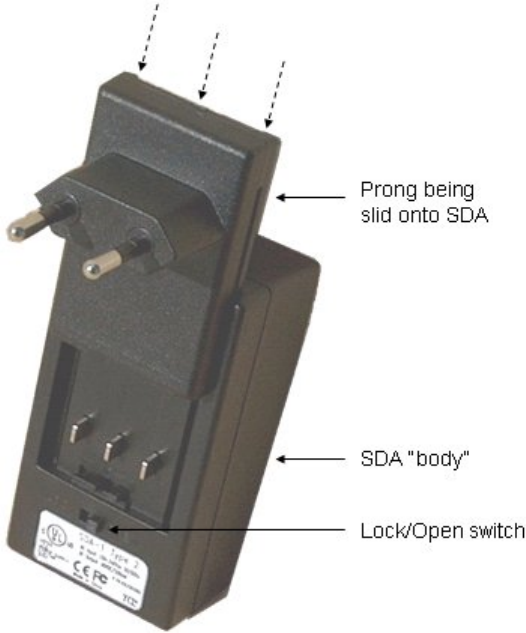
Changing the SDA-1 Type II Plug Prongs
The SDA-1 Type II allows you to attach plug prongs suited to the electrical wall socket of the
country in which you are installing the equipment. Therefore, before plugging the SDA-1
Type II into the electrical outlet, ensure that the correct prongs are attached to the SDA-1
Type II.
To change the SDA-1 Type II plug prongs:
1. On the rear of the SDA-1 Type II, slide the locking switch to OPEN.
2. Remove the prongs by sliding the prongs in the direction away from the switch.
3. Insert the desired prongs by aligning the prongs with the SDA-1 Type II's prong groove,
and then sliding the prongs onto the SDA-1 Type II until it reaches the end of the groove.
4. Lock the prongs in place by moving the switch to LOCK.
605-0000-706 ProST Installation User Guide-Rev H
54
Plugging the SDA-1 Type II into an Electrical Wall Outlet
After you have attached the suitable plug prongs onto the SDA-1 Type II , you can plug it
into a standard electrical wall outlet (110/240 VAC), as illustrated below.
Connecting to Power
55
Verify that your SDA-1 Type II is on and receiving power by checking that the LED labeled
POWER is lit (see SDA-1 Type II LED description). If it is not lit, see Troubleshooting.
Using SDA-4S Type II and SDA-4S/VL Type II
The SDA-4S adapters are plugged into a standard electrical wall outlet (110/240 VAC) using an
AC power cord. The appropriate AC power cord is supplied according to the country of use.
The cable setup between the SDA-4S and power outlet includes the following:
Connector: AC IEC 60320 type (female)
Plug: The appropriate plug type is supplied according to the country of use
Cable: 3x1.z0 mm, 10A / 250 VAC (maximum length is 180 cm)
To connect the SDA-4S to the AC power supply:
605-0000-706 ProST Installation User Guide-Rev H
56
1. Connect the power plug female, at the end of the AC power chord, into the AC power socket
located on the left panel of the SDA-4S.
2. Plug the power plug male, at the other end of the AC power chord, into the AC power outlet
(110-240 VAC).
3. Verify that the power is received by the SDA-4S by checking that the POWER LED light is
on.
Verify that your SDA-4S is on and receiving power by checking that the LED labeled POWER is lit
(see SDA-4S LED description). If it is not lit, see Troubleshooting.
Connecting to Power
57
CONNECTING POWER CABLE FOR SDA-4SDC
Power Cable Connection
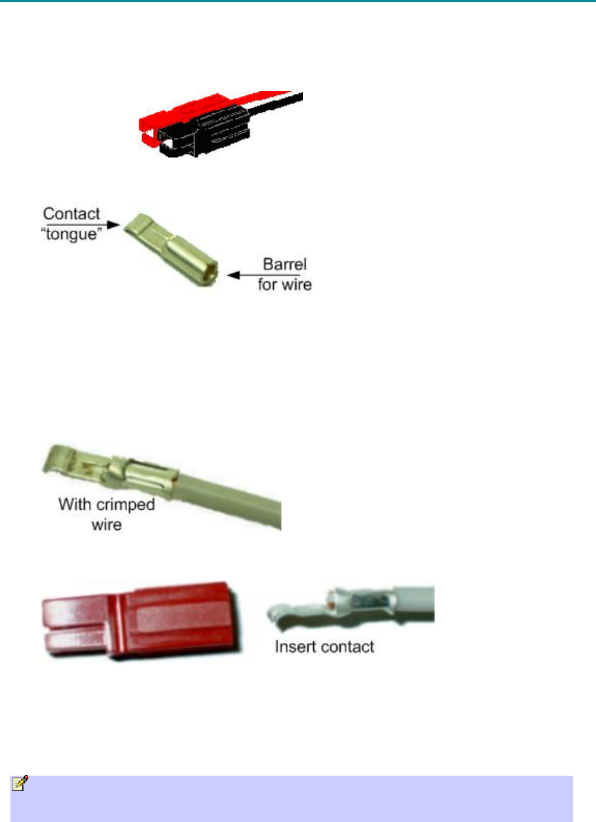
In the SDA-4SDC installation Kit there are two polarized and genderless unassembled Anderson
Powerpole power connectors: red for positive connection and black for the negative connection.
Power connectors (Anderson Powerpole)
The power connectors consist of housing (hood and a contact pins). The contact pin is displayed
below:
Housing the Connectors
The power connectors are supplied unassembled. Therefore, you need to crimp the power wires
to the connector's contact pins, and then house them in the Powerpole hood.
Crimping the power wires to the connectors:
1. Insert the wire into the contact pin's barrel, and then, with a standard crimping tool crimp
the barrel tightly onto the wire (recommended 16 AWG cable wire).
2. Insert the contact into the hood with the contact's tongue pointing downwards and snap
into place. Ensure that the housing spring mates with the underside of the contact's tongue.
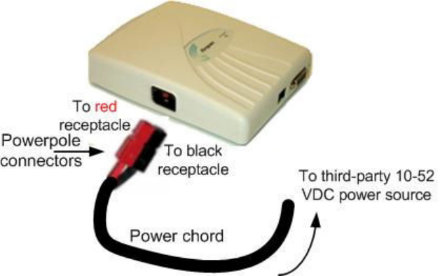
Connecting to the SDA-4SDC
Once you have crimped the power cord to the Powerpole connectors, connect the power
connectors to the SDA-4SDC power receptacles.
To connect the power cord to the SDA-4SDC
Note: The plastic housings are held together with dovetail joints. Always slide these joints
together! They will be damaged if you try to snap them together or apart. They ONLY slide
together in one direction. This should be obvious looking at them carefully.
605-0000-706 ProST Installation User Guide-Rev H
58
1. Assemble the red and black plastic housings together. Mate both connectors, by sliding
them along the dovetail joints. When looking at the connector side (not the wire side), the
red connector should be on the left and the black on the right. The housing dovetails
should be mated fully.
2. Connect the power connectors to the SDA-4SDC power receptacles so that the connectors'
color matches the receptacle's color, red to red (positive), and black to black (negative).
3. Connect the other end of the power cord to the third-party DC power source. Ensure that
the positive and negative sides are correct.

59
CONNECTING LIGHTNING AND SURGE PROTECTOR
The optional third-party lightning and surge protector (PolyPhaser) is implemented in the following
deployment scenarios:
ODU-to-IDU cable length of 40 meters or more (optional to use surge protector unless
required by local law)
Deployment of CPE in geographical areas that frequently experience severe lightning
storms
The lightning and surge protector protects the ODU-to-IDU CAT 5e cable's six used wires (two -48
VDC wires and four Ethernet Tx and Rx wires) from any electrical surges due to lighting strikes.
The protector is installed outdoors on the CAT 5e cable that connects between the CPE and the SDA.
In other words, two CAT 5e cables are required for the following connections:
CPE-to-protector connection
Protector-to-IDU connection
Warning: Do not install the lightning and surge protector during adverse weather
conditions when the threat of lightning strike is possible.
Note: The protector unit must be grounded to a low-impedance (low R and low L) ground
system to operate properly.
Note: For pricing and ordering of the PolyPhaser lightning and surge protector, contact
your Airspan representative.
To install the lightning protector:
1. Connect the protector in the direction according to the labels. The end labeled SURGE
accepts the cable from the ProST; the end labeled PROTECTED accepts the cable from the
IDU.
2. Feed the CAT 5 cable through the grommet (for each side). If the RJ-45 connector is
already crimped to the other end, ensure that you have fed the cable through the gland nut
beforehand. The gland nut secures the cable to the grommet.
3. Strip about 0.25" (6.35 mm) of the cable sheath and expose about 0.03" (0.8 mm) of the
strands/wires.
4. Secure the wires to the protector's terminal block using the two spot ties. Each side of the
data and DC assembly has + or – markings to ensure lines entering (surge side) match
lines exiting (protected side).
605-0000-706 ProST Installation User Guide-Rev H
60
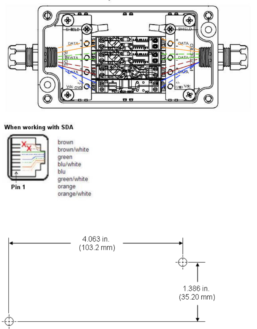
PolyPhaser Wiring Diagram
When working with SDA
5. Mount and ground the protector outdoors with the provided 2 x 8-32 screws according to
the fixing template illustrated below (showing distances between centers of the two
mounting holes). The unit may be mounted/grounded on a nearby plate or bulkhead panel
that is bonded to an earth-ground system.
6. Attach the protector's lid by using the four M4 x 20-mm screws. Ensure that the neoprene
gasket on the lid is not loose or out of the groove.
7. Secure the CAT 5e cable to the grommet by fastening the gland nut.
Connecting Lightning and Surge Protector
61
Lightning and Surge Protection Connection Scenarios
The figures below illustrate various lightning and surge protector connectivity scenarios.
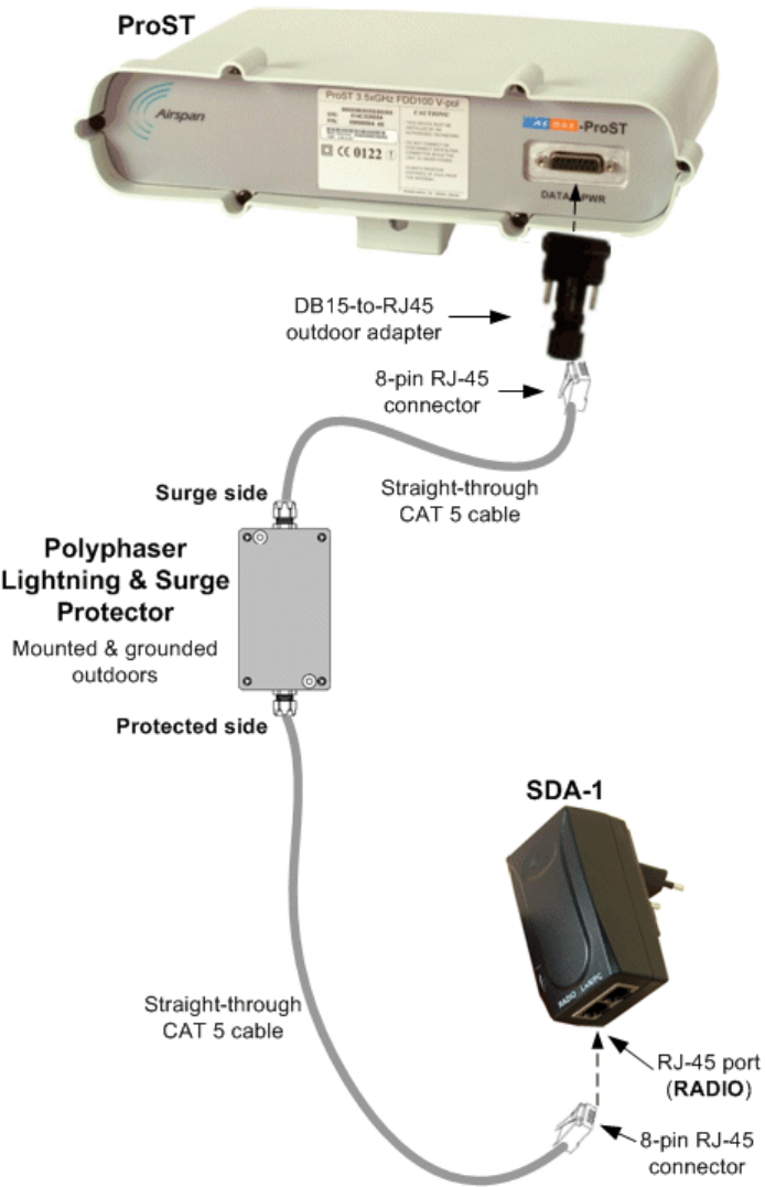
The figure below illustrates the connectivity of the lightning and surge protector using the SDA-
1 Type II adapter.
605-0000-706 ProST Installation User Guide-Rev H
62
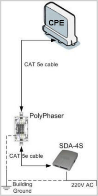
SDA + PolyPhaser + CPE
Connecting Lightning and Surge Protector
63
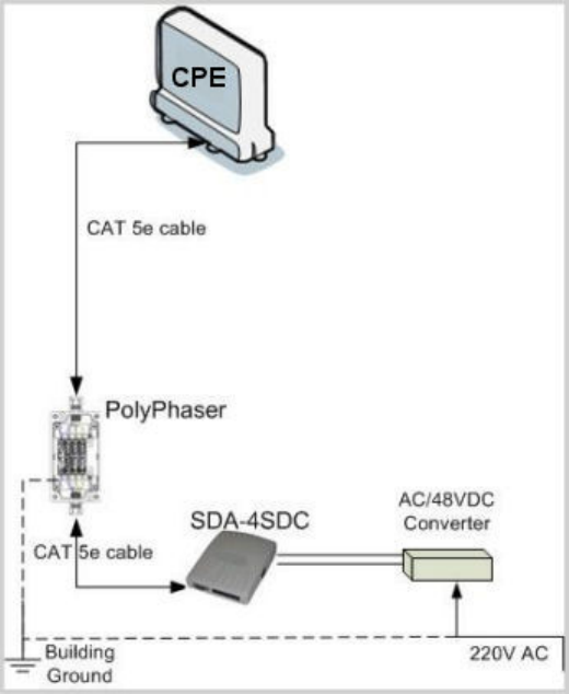
SDA-4SDC + PolyPhaser + CPE

64
RSSI LED PLUG ADAPTER
Antenna Alignment using RSSI LED Plug Adapter
The RSSI LED Plug is a small adapter that allows you to accurately position (align) the ProST for
optimal radio frequency signal reception with the Base Station. The RSSI LED Plug adapter provides
LEDs that indicate the ProST's received signal strength (RSS) with the Base Station.
Once the RSSI LED Plug adapter is connected, you need to orientate the ProST (or third-party
external antenna) to the position where the RSSI LEDs display the highest RSS measurements.
The RSSI LED Plug adapter connects between the ProST and SDA by a CAT 5 cable(s). The RSSI
LED Plug adapter provides two 15-pin D-type ports: one for the ProST side, and the other for the
SDA side.
The RSSI LED Plug adapter can be connected in one of the following manners:
One end connects directly to the ProST's 15-pin D-type port, and the other end connects to
the SDA (IDU adapters) by a CAT 5 cable.
Both ends connect to the ProST and SDA by a CAT 5 cable.
The following describes the RSS LED Plug adapter's cable setup:
Cables: two straight-through cables for connecting the RSSI LED adapter to both the SDA
and ProST
Connectors:
o ProST side: 15-pin D-type male (only 6 pins used)
o RSSI LED Plug adapter:
o ProST side: 15-pin D-type female
o SDA side: 15-pin D-type male
o SDA side: 15-pin D-type male
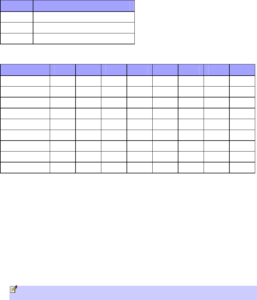
RSSI LED Plug Adapter
65
LED Status
The RED Power LED functions as follows:
Status Description
ON ProST receiving power from SDA
OFF No power being received
Blinking Data transmission via Ethernet LAN
The LED status for each RSSI level is defined in the following table:
RSSI Level dB LED 0 LED 1 LED 2 LED 3 LED 4 LED 5 LED 6 LED 7
97dB- 0 0 0 0 0 0 0 0
93 - 96 1 0 0 0 0 0 0 0
89 - 92 1 1 0 0 0 0 0 0
83 - 88 1 1 1 0 0 0 0 0
79 - 82 1 1 1 1 0 0 0 0
75 - 78 1 1 1 1 1 0 0 0
71 - 74 1 1 1 1 1 1 0 0
67 - 70 1 1 1 1 1 1 1 0
66 dB+ 1 1 1 1 1 1 1 1
Before connecting the power adapter to the ProST, you need to connect the AC power cable (that
connects to the subscriber,s power outlet) to the adapter, as described in the following procedure.
To connect the RSSI LED Plug Adapter:
1. Connect the 15-pin D-type male connector, at one end of the straight-through cable, to the
ProST.
2. Connect the 15-pin D-type female connector, at the other end of the straight-through cable
from the ProST, to the RSSI LED adapter.
3. Connect the 15-pin D-type male connector, at one end of the straight-through cable, to the
SDA.
4. Connect the 15-pin D-type male connector, at the other end of the straight-through cable
from the SDA, to the RSSI LED adapter.
Note: You can connect the RSSI LED Plug adapter's 15-pin male port directly to the ProSt's
15-pin female port, instead of using a cable.
The following diagram illustrates the RSSI LED plug connections:
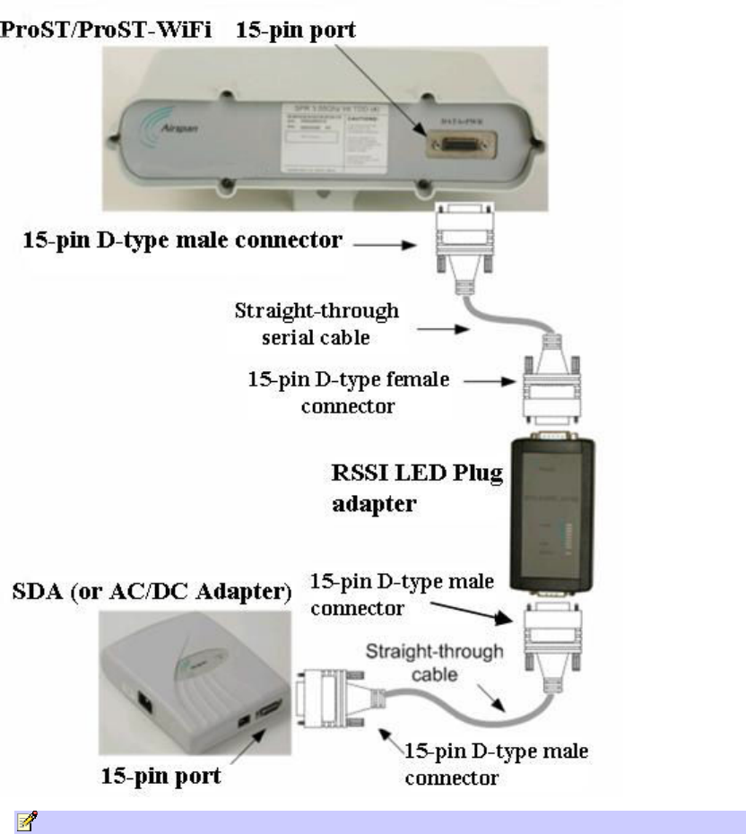
605-0000-706 ProST Installation User Guide-Rev H
66
Note: RSSI response time has been proportionally increased to enable longer alignment.
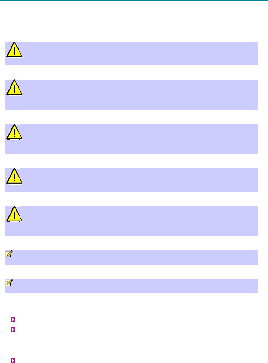
67
CONNECTING EXTERNAL ANTENNA
The ProST model without a built-in antenna provides an N-type port for connecting a third-party
external antenna. The addition of an external antenna allows greater RF sector coverage than the
standard ProST built-in antenna model. The external antenna is typically implemented in scenarios
where the ProST is deployed at relatively far distances from the base station.
Warning: Before connecting the external antenna, ensure that the ProST is not
connected to the power source.
Warning: Before powering on the ProST, ensure that some type of equipment such as
an antenna or an RF attenuator is connected to the N-type receptacle. This eliminates the risk
of irreversibly damaging the ProST device.
Warning: It is the responsibility of the person installing the ProST to ensure that only
those antennas certified with the product are used. The use of any antenna other than those
certified with the product is expressly forbidden.
Warning: The external antenna must not be co-located or operating in conjunction
with any other antenna or transmitter.
Warning: The ProST and external antenna should be installed ONLY by experienced
installation professionals who are familiar with the local building and safety codes and are
licensed by the appropriate government authorities.
Note: The ProST model that provides an N-type connector for attaching a third-party
external antenna does not contain an internal, built-in antenna.
Note: It is recommended that the same antenna polarization (i.e. horizontal or vertical)
exists at both ends of the link (i.e. base station and subscriber site).
The following lists the cable setup for attaching the external antenna:
Cable: RF coaxial
Connector: N-type male
To connect a third-party external antenna to the ProST:
Connect the N-type male connector of the third-party antenna to the N-type receptacle
located on the ProST's bottom panel (labeled ANTENNA), as displayed below.
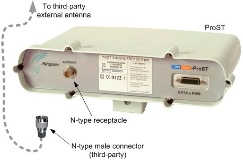
605-0000-706 ProST Installation User Guide-Rev H
68
69
TROUBLESHOOTING
The table below provides some possible solutions to problems that may arise if the ProST is
incorrectly installed:
Problem Possible Cause Solution
No electricity at wall outlet Ensure household provides electricity
to the specific wall outlet (professional
electrician required)
SDA-1 prongs not plugged
entirely into wall outlet socket Ensure SDA-1 plug prongs are
completely inserted into wall outlet
SDA-1 plug prongs attached
incorrectly to SDA-1 Remove the SDA-1 plug prongs and
reinsert them, ensuring the following:
Prongs are inserted into the
SDA-1's prong grooves
Prongs slid to the end
Switch is in LOCK position
SDA-1 (and
therefore,
ProST) not
receiving power
--POWER LED
is off
Network cables (radio and
LAN) inserted into incorrect
RJ-45 ports of the SDA-1
Ensure that the cables are plugged into
the correct SDA-1 ports:
Port labeled RADIO: for
ProST-to-SDA-1 connectivity
Port labeled LAN/PC: for
computer-to-SDA-1
connectivity

70
TRADEMARKS AND COPYRIGHTS
1. © Airspan Networks Inc 2007
2. The information in this document is proprietary to Airspan Networks Inc. This
document may not in whole or in part be copied, reproduced, or reduced to any
medium without prior consent, in writing, from Airspan Networks Incorporated.
3. This manual is subject to revision.
4. All rights reserved.
5. Right of modification reserved.
6. This manual is supplied without liability for errors or omissions.
7. No part of this manual may be reproduced or used except as authorised by contract
or other written permission.
8. This equipment is conditioned by the requirement that no modifications are made
to the equipment unless the changes or modifications are expressly approved by
Airspan.
9. Prerequisite skills: Personnel installing, commissioning, and maintaining the
Airspan products must have a basic knowledge of telephony and radio
communications, and have experience in installing, commissioning and maintaining
telecommunications products. Airspan provides a range of comprehensive training
courses specifically aimed at providing operators/users of Airspan products with the
prerequisite skills to install, commission and or maintain the product. The courses
are tailored to provide the level of training required by the operator/user.
10. AS.MAX, MacroMAX, MicroMAX, HiperMAX Netspan, EasyST and ProST are brands
of Airspan Networks Inc.

71
CONTACT INFORMATION
UK Office for sales and general enquiries
Airspan Communications Ltd
Cambridge House
Oxford Road
Uxbridge
Middlesex
UB8 1UN
Call +44 (0) 1895 467100
Fax +44 (0) 1895 467101
email sales@ airspan.com
Internet: Airspan.com
Customer Service Help-Desk for customer service emergency
Airspan Communications Limited
Cambridge House
Oxford Road
Uxbridge
Middlesex
UB8 1UN
Int. Tel: +44 (0) 1895 467 467
Int. Fax: +44 (0) 1895 467 472
E-mail: Support@Airspan.com

72
REVISIONS
Revision Level Date Main Changes
A 24-11-2005 Initial Document
B 28-3-2006 Warning Removed Additions
C 23-4-2006 RSSI LED Plug
D 20-06-2006 Standardize document + additions
E 17-06-2006 Corrections
F 21-09-2006 SDA-4SVL & DC, removed PSU, corrections
G 11-02-2007 additional ranges + additions
H 08-2007 additional ranges, polyphaser info

73
WARNINGS
1. Disclaimer
Every effort has been made to ensure the accuracy of the material provided herein; however,
Airspan assumes no responsibility regarding the use of the material. Additionally, Airspan
makes no representations or warranties, either expressed or implied, regarding the contents
of this product. Airspan Networks Inc. shall not be liable for any misuse regarding this
product.
Any product performance limits stated within this document are for information purposes
only and should be considered as indicative.
1.1 Safety Warnings
1. Read this User Manual and follow all operating and safety instructions.
2. Keep all product information for future reference.
3. This product is supplied with a grounding power plug. Do not defeat this important safety
feature.
4. Warning: High voltages exist inside the product - do not remove the lid or base: No user
serviceable parts inside.
5. CAUTION: DOUBLE POLE/NEUTRAL FUSING - Always replace the fuse with the correct type
and current rating.
6. Position the power cord to avoid possible damage; do not overload wall outlets.
7. Do not place this product on or near a direct heat source, and avoid placing objects on the
terminal.
8. Do not operate this device near water or in a wet location.
9. Use only a damp cloth for cleaning. Do not use liquid or aerosol cleaners. Disconnect the
power before cleaning.
10. Protect the terminal by disconnecting the power if not used for long periods.
11. Mount the terminal in a Telco rack on a stable horizontal surface.
12. The radio antenna units must not be located near power lines or other electrical power
circuits.
13. The radio transceiver must be properly grounded to protect against power surges and
accumulated static electricity. It is the user’s responsibility to install this device in
accordance with the local electrical codes: correct installation procedures for grounding of
the transceiver unit, mast, lead-in wire and discharge unit, location of discharge unit, size
of grounding conductors and connection requirements for grounding electrodes.
14. Installation of the transceiver must be contracted to a professional installer.
15. Disconnect Device. The socket outlet shall be installed near the equipment , easily
accessible and will act as the disconnect for the device.
16. When installed in the final configuration, the product must comply with the applicable
Safety Standards and regulatory requirements of the country in which it is installed. If
necessary, consult with the appropriate regulatory agencies and inspection authorities to
ensure compliance.
1.2 Important Warning Symbols
The following symbols may be encountered during installation or troubleshooting. These warning
symbols mean danger. Bodily injury may result if you are not aware of the safety hazards involved
in working with electrical equipment and radio transmitters. Familiarize yourself with standard
safety practices before continuing.
605-0000-706 ProST Installation User Guide-Rev H
74
Electro-Magnetic Radiation High Voltage
1.3 Important Service Information
1. Refer all repairs to qualified service personnel. Do not remove the covers or modify any
part of this device, as this will void the warranty.
2. Disconnect the power to this product and return it for service if the following conditions
apply:
a. The terminal does not function after following the operating instructions outlined in this
manual.
b. Liquid has been spilled, a foreign object is inside, or the terminal has been exposed to
rain.
c. The product has been dropped or the housing is damaged.
3. Locate the serial number of the terminal, antenna, and transceiver and record these on
your registration card for future reference. Use the space below to affix serial number
stickers. Also record the MAC address, located on the back of the terminal.
1.4 UL Information
- The equipment must be properly grounded according with NEC and other local safety code
requirements
- Reminder to all the BWA system installers: Attention to Section 820-40 of the NEC which
provides guidelines for proper grounding and, in particular, specifies that the cable ground
shall be connected to the grounding system of the building, as close to the point of cable
entry as is practical.
1.5 CE Notice
The MacroMAX shelf carries the CE mark to demonstrate conformity with the Radio
Equipment and Telecommunications Terminal Equipment and the Mutual recognition of their
conformity (R&TTE) directive 1999/5/EC.
WARNING: This is a class A product. In a domestic environment this product may cause radio
interference in which case the user may be required to take adequate measures.
Installation
The transceiver and antenna equipment must be installed by a qualified professional installer
and must be installed in compliance with regional, national, and local regulations. It is the
responsibility of the system installer and/or system operator to ensure the installed system
does not exceed any operational constraints identified by local regulations.
Refer to the sections in this product User Guide for detailed information about the correct
installation steps to ensure power and frequency settings are set correctly before connecting
the antenna.
Antenna Selection
Refer to the product User Guide for a list of Airspan Networks approved antennas. Antennas
not listed in the User Guide are outside the scope of this Declaration.
CAUTION: European Directive 1999/519/EC details basic restrictions and reference levels on
human exposure to electromagnetic fields as advised by the ICNIRP. The directive states that
adherence to these recommended restrictions and reference levels should provide a high
level of protection as regards the established health effects that may result from exposure to
such fields.
Warnings and Cautions
75
By the very nature of the system design and installation users will not find them selves
within close proximity of the subscriber terminals.
Standards EN50383 and EN50385 are the applicable harmonised standards for EM fields
generated by fixed wireless equipment.
The Electromagnetic fields generated by the Central Terminal antenna are below the
recommended safe levels at all distances greater than 65 cm from an approved Airspan
antenna.
The safe distance from a non-approved antenna of length D and Sector Angle δ may be
calculated using the formula:
Safe distance, r = 36 / (π * D * δ)
1.6 European Community, Switzerland, Norway, Iceland, and
Liechtenstein
Declaration of Conformity with Regard to the R&TTE Directive 1999/5/EC
English:
This equipment is in compliance with the essential requirements and other relevant
provisions of Directive 1999/5/EC.
Deutsch:
Dieses Gerät entspricht den grundlegenden Anforderungen und den weiteren
entsprecheneden Vorgaben der Richtlinie 1999/5/EU.
Dansk:
Dette udstyr er i overensstemmelse med de væsentlige krav og andre relevante
bestemmelser i Directiv 1999/5/EF.
Español:
Este equipo cumple con los requisitos esenciales asi como con otras disposiciones de la
Directive 1999/5/EC.
Eλληνικά:
Αυτός ο εξοπλισµός συµµορφώνεται µε τις ουσιώδεις απαιτήσεις και τις λοιπές διατάξεις της
Οδηγίας 1999/5/EΚ.
Français:
Cet appareil est conforme aux exigencies essentialles et aux autres dispositions pertinantes
de la Directive 1999/5/EC.
Íslenska:
Þessi búnaður samrýmist lögboðnum kröfum og öðrum ákvæðum tilskipunar 1999/5/ESB.
Italiano:
Questo apparato é conforme ai requisiti essenziali ed agli altri principi sanciti dalla Direttiva
1999/5/EC.
Nederlands:
Deze apparatuur voldoet aan de belangrijkste eisen en andere voorzieningen van richtlijn
1999/5/EC.
Norsk:
Dette utstyret er i samsvar med de grunnleggende krav og andre relevante bestemmelser i
EU-directiv 1999/5/EC.
Português:

605-0000-706 ProST Installation User Guide-Rev H
76
Este equipamento satisfaz os requisitos essenciais e outras provisões da Directiva
1999/5/EC.
Suomalainen:
Tämä laite täyttää direktiivin 1999/5/EY oleelliset vaatimukset ja on siinä asetettujen
muidenkin ehtojen mukainen.
Svenska:
Denna utrustning är i överensstämmelse med de väsentliga kraven och andra relevanta
bestämmelser i Direktiv 1999/5/EC.
The Declaration of Conformity related to this product can be obtained from
product_management@Airspan.com
1.7 CAUTION
Any modifications to this device not expressly authorised by the manufacturer could void the
user's authority to operate this device.
Responsible party for compliance is:
David Mann, Airspan Networks Inc.,Cambridge House, Oxford Rd, Uxbridge, Middlesex,
England, UB8 1UN. Telephone (44) 1 895 467450.
1.8 Lightning Protection
WARNING: The following notes are general recommendations for the system. The wireless
equipment should be installed by a qualified professional installer and must follow local and
national codes for electrical grounding and safety. Failure to meet safety requirements
and/or use of non-standard practices and procedures could result in personal injury and
damage to equipment. A direct lightning strike may cause serious damage even if these
guidelines are followed.
All outdoor wireless equipment is susceptible to lightning damage from a direct hit or induced
current from a near strike. Lightning protection and grounding practices in local and national
electrical codes serve to minimize equipment damage, service outages, and serious injury.
Reasons for lightning damage are summarized as:
- Poorly grounded tower/antenna sites that can conduct high lightning strike energy into
equipment.
- Lack of properly installed lightning protection equipment that can cause equipment failures
from lightning induced currents.
A lighting protection system provides a means by which the energy may enter earth without
passing through and damaging parts of a structure. A lightning protection system does not
prevent lightning from striking; it provides a means for controlling it and preventing damage
by providing a low resistance path for the discharge of energy to travel safely to ground.
Improperly grounded connections are also a source of noise that can cause sensitive
equipment to malfunction.
A good tower grounding system disperses most of the surge energy from a tower strike away
from the building and equipment. The remaining energy on the RF cable shield and center
conductor can be directed safely to ground by using a lightning arrestor in series with the RF
cable.
To limit the equipment damage due to a lightning strike, the following practices are
recommended for the wireless system:
- Provide direct grounding from the antenna mounting bracket, the radio and antenna and
the lightning arrestors to the same ground point at the base of the tower or a ground bus on
the building. Use the grounding screws on the antenna bracket and the radio and antenna for
terminating the ground wires.
Warnings and Cautions
77
- Install one RF lightning protector between the radio and antenna in series with the RF
cable.
- A lightning arrestor in series with the RF cable at the point of entry to the building.
- Install a lightning arrestor in series with the IF cable at the transceiver on the tower/mast.
- The AC wall outlet ground for the MacroMAX terminal must be connected to the same
grounding system as the radio and antenna lightning protectors.
78
GLOSSARY
B
BPSK: Binary Phase Shift Keying
BS: Base Station
BWA: Broadband Wireless Access
C
CID: Connection Identifier Number
CPE: Customer Premises Equipment (interchangeable with ST)
D
dB: Decibel
dBm: Power ratio in dB (decibel) of the measured power referenced to one milliwatt
DL: Downlink
F
FDD: Frequency Division Duplex
FEC: Forward Error Correction
FTP: File Transfer Protocol
G
GHz: Gigahertz. One GHz represents 1 billion cycles per second
H
HFDD: Half-Duplex FDD
Hz: Hertz
I
IAD: Integrated Access Device
IDU: Indoor Unit (i.e. SDA-1 Type II, SDA-4S Type II, or SDA-4S/VL Type II)
IP: Internet Protocol
ISP: Internet Service Provider
L
LAN: Local-Area Network
M
Glossary
79
MAC: Media Access Controller. The next layer up from the PHY.
Mbit/s: Megabits per second
MHz: Megahertz (one million cycles per second)
MIB: Management Infomation Base
N
NLOS: Non Line-of-Sight radio propagation path
O
ODU: Outdoor Unit (i.e. ProST)
OFDM: Orthogonal Frequency Division Multiplexing
Q
QAM: Quadrature Amplitude Modulation
QoS: Quality of Service, which is used to specify level of data throughput
QPSK: Quadrature Phase Shift Keying
R
RF: Radio Frequency
Rx: Receive
S
SDA-4S: Convenient term for either the SDA-4S Type II or SDA-4S/VL adapters
SF: Service Flow
SME: Small and Medium-sized Enterprise
SNMP: Simple Network Management Protocol
SNR: Signal-to-Noise Ratio
ST: Subscriber Terminal (interchangeable with CPE or SS)
T
TDMA: Time Division Multiple Access. Technology for delivering digital wireless service using time-
division multiplexing (TDM)
TNV: Telecommunications Network Voltage
Tx: Transmit
U
UGS: Unsolicited Grant Service. Used to provide fixed bandwidth slots on the uplink for an ST to
transmit data at regular intervals. The bandwidth should be used by the UGS SF, however
the final decision of which SF (if any) uses the bandwidth slot is made by the ST.
605-0000-706 ProST Installation User Guide-Rev H
80
V
VoIP: Voice over Internet Protocol
W
WiMAX: WiMAX is a wireless industry coalition whose members are organized to advance IEEE
802.16 standards for broadband wireless access (BWA) networks.
81
INDEX
A
Antenna Alignments
Orientating when Pole Mounted............. 30
Orientating when Wal Mounted) ............ 30
Architecture.......................................... 12
B
Bandwidth Speed................................... 12
Benefits................................................ 12
Block Diagram....................................... 12
BPSK ................................................... 12
C
Cabling ProST
Connecting to AC Power....................... 50
Connecting to DC Power....................... 50
Connecting to External Antenna ............ 67
Connecting to PC ................................ 40
Connecting to SDA-1 ........................... 40
Changing SDA-1 Plug Prongs................... 50
Components.......................................... 12
Computer, Connecting to ProST ............... 40
D
Dimensions
ProST................................................ 22
SDA-1 ............................................... 22
F
Features............................................... 12
L
LEDs of SDA-1, Descriptions.................... 22
Lightning Protector
Connecting to ProST............................ 50
M
Mounting
Pole Mounting..................................... 30
Wall Mounting..................................... 30
O
Overview.............................................. 12
P
Pole Mounting ....................................... 30
Ports
ProST Port Description......................... 22
SDA-1 Port Descriptions....................... 22
Power
Changing SDA-1 Plug Prongs ................ 50
Connecting Lightning Protector.............. 50
Connecting to AC Power....................... 50
Connecting to DC Power....................... 50
ProST
Connecting Lightning Protector.............. 50
Connecting to AC Power....................... 50
Connecting to DC Power....................... 50
Connecting to PC ................................ 40
Connecting to SDA-1 ........................... 40
Models .............................................. 12
Physical Dimensions ............................ 22
Pole Mounting..................................... 30
Port Description.................................. 22
Wall Mounting..................................... 30
Protocol Stack ....................................... 12
Q
QAM .................................................... 12
QPSK ................................................... 12
S
SDA-1
Changing Plug Prongs.......................... 50
Connecting to ProST............................ 50
LED Description .................................. 22
Physical Dimenisons ............................ 22
Port Descriptions................................. 22
T
Theory of Operation ............................... 12
Troubleshooting..................................... 69
W
Wall Mounting ....................................... 30

82
How to find out
more about
Airspan products
and solutions
Airspan has offices in the following
countries:
Europe
Czech Republic
Poland
Russia
United Kingdom
Africa
South Africa
Americas
United States
Asia Pacific
Australia
China
Indonesia
Japan
New
Zealand
For more information about Airspan, its
products and solutions, please visit our
Web site:
www.airspan.com
Or write to us at one of the addresses
below.
We will be delighted to send you
additional
information on any of our products and
their
applications around the world.
Worldwide Headquarters:
Airspan Networks Inc.
777 Yamato Road, Suite 105
Boca Raton, Florida 33431-4408
USA
Tel: +1 561 893 8670
Fax: +1 561 893 8671
Main Operations:
Airspan Communications Ltd.
Cambridge House, Oxford Road,
Uxbridge, Middlesex UB8 1UN
UK
Tel: +44 (0) 1895 467 100